

Page 1

Solid-State Memory Camcorder
Operating Instructions
4-693-039-13 (1)
GB
PXW-Z450
Software Version 3.0
© 2016 Sony Corporation
Page 2

0002
Table of Contents
1. Overview
Name and Function of Parts .............................................. 3
Screen Display .................................................................. 13
2. Preparation
Preparing a Power Supply ............................................... 20
Attaching a Viewfinder .................................................... 21
Using the Camcorder for the First Time...........................23
Mounting and Adjusting the Lens ...................................24
Preparing the Audio Input System .................................. 25
Attaching and Adjusting Peripheral Devices ...................26
Handling SxS Memory Cards ........................................... 27
Handling SD Cards for Saving Configuration Data .......... 29
Using a Media Adaptor .................................................... 30
3. Settings and Adjustments
Format Settings ................................................................ 31
Expansion of Imaging Dynamic Range ...........................37
Adjusting the Black Balance and White Balance ............ 38
Setting the Electronic Shutter .......................................... 40
Setting Auto Iris ...............................................................41
Adjusting the Audio Level ............................................... 42
Setting Time Data ............................................................ 44
5. Network Configuration
Network Functions Supported by the Camcorder...........58
Connecting Devices using Wireless LAN ......................... 59
Connecting to the Internet ..............................................63
Transferring Files .............................................................. 67
Transmitting Streaming Video and Audio ...................... 69
Streaming High Quality Video ......................................... 70
Using Wi-Fi Remote Control ............................................71
Configuring from the Web Menu .................................... 73
Supported Network Functions and Operating
Limitations ............................................................... 78
6. Clip Operations
Clip Operations on the Thumbnail Screen.......................79
Thumbnail Menu ............................................................. 85
7. Menu Display and Settings
Setup Menu Organization ................................................ 86
Basic Setup Menu Operations .......................................... 88
Editing the User Menu ..................................................... 90
Menu List ..........................................................................92
Assigning Functions to Assignable Switches ................117
8. Saving and Loading User Configuration Data
9. Connecting External Devices
Connecting a Remote Control Unit ................................127
Connecting an External Monitor ....................................129
Managing/Editing Clips with a Computer ....................130
Configuring a Shooting and Recording System ............132
Recording External Input Signals...................................135
10. Maintenance and Inspection
Maintenance ..................................................................136
Error/Warning System ...................................................137
11. Appendix
Messages Displayed During Operation..........................140
Items Saved in User Data ...............................................146
Special Recording Support by Recording Format .........156
Picture Cache Rec Mode Settings ..................................157
Usage Precautions ..........................................................158
Specifications .................................................................160
4. Shooting
Basic Operations ............................................................... 46
Advanced Operations .......................................................48
Proxy Data ........................................................................ 53
Planning Metadata .......................................................... 55
Obtaining Location Information (GPS) ............................57
User Configuration Data .................................................120
User Files ........................................................................121
ALL Files .........................................................................122
Scene Files ......................................................................123
Reference Files ...............................................................124
Lens Files ........................................................................125
Gamma Files...................................................................126
Page 3
1. Overview
1. Overview
000
3
Name and Function of Parts
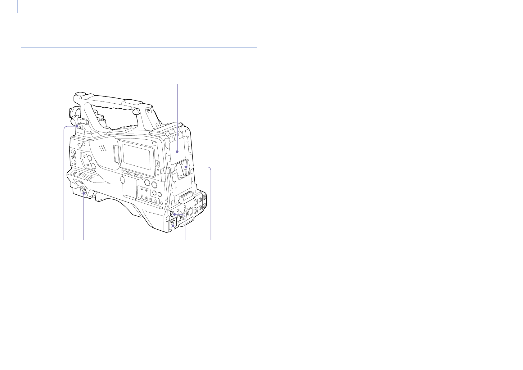
Power Supply
6
5. Battery attachment shoe
Attach a BP-FLX75 Battery Pack. Alternatively,
you can attach an AC-DN2B/DN10 AC Adaptor to
operate the camcorder from an AC power supply.
“Preparing a Power Supply” (page 20)
[Note]
For your safety, and to ensure proper operation of the
camcorder, Sony recommends the use of the BP-FLX75
Battery Pack.
6. Camera adaptor connector
Enables connection of a CA-TX70/FB70 HD Camera
Adaptor. To connect an adaptor, remove the
cover.
[Note]
Not supported in the return video display by the camcorder.
1 4 5
2 3
1. LIGHT (video light) switch
Determines how a video light connected to the
LIGHT connector (page 4) is turned on and off.
AUTO: When the POWER switch of the video light
is in the on position, the video light is turned
on automatically while the camcorder is
recording.
MANUAL: You can turn the video light on or off
manually, using its own switch.
[Note]
When the camcorder is set for recording in Picture Cache Rec
mode, it is not possible to turn on the light before operation
to start recording is carried out (or while data is being stored
in memory).
2. POWER switch
Turns the main power supply on () and off ().
3. DC IN (DC power input) connector (XLR type,
4-pin, male)
4. DC OUT 12V (DC power output) connector
(4-pin, female)
Supplies power for an optional WRR855S/860C/861/862 UHF Synthesizer Diversity
Tuner or HDVF-L750 Viewfinder (maximum 1.8 A).
[Note]
Do not connect any equipment other than the UHF
synthesized diversity tuner.
Page 4
1. Overview: Name and Function of Parts
000
4
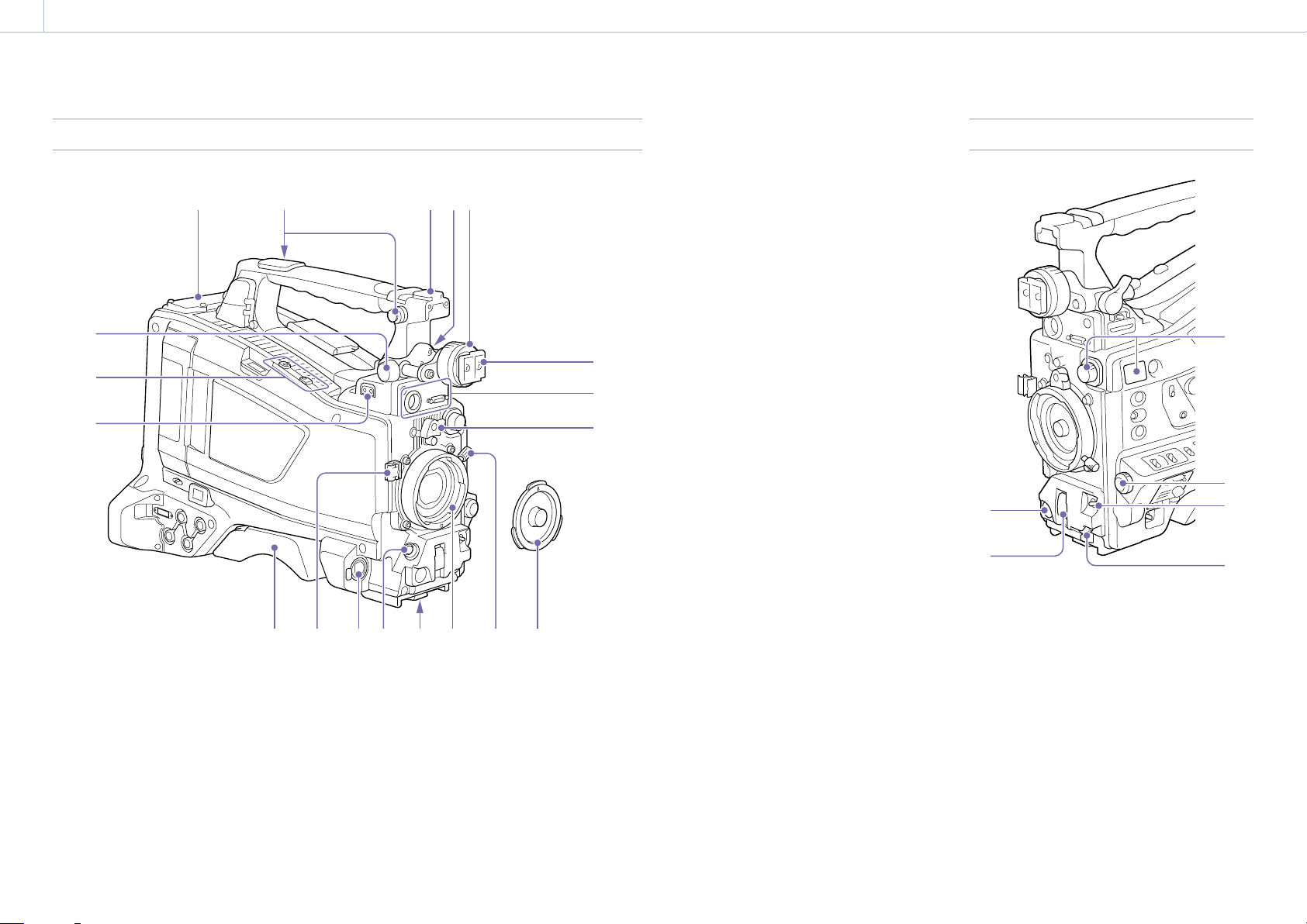
Accessory Attachments
1
9
10
11
1. Wireless receiver insertion slot (page 25)
“Attaching a Wireless Receiver” (page 25)
2. Shoulder strap fitting (page 26)
3. Accessory shoe (page 26)
4. Viewfinder front-to-back positioning lever
(page 21)
5. Viewfinder left-to-right positioning ring
(page 21)
6. Viewfinder attachment shoe (page 21)
12
2
3 4
5
6
7
8
14 17 18 1916
1513
7. VF (viewfinder) connectors (26-pin,
rectangular and 20-pin, round)
The analog interface connector (20-pin) is for
connection of an HDVF series viewfinder, and
the digital interface connector (26-pin) is for
connection of a CBK-VF02 HD viewfinder.
Connect a viewfinder connection cable to the
connector compatible with the viewfinder being
used.
[Notes]
Do not connect viewfinders to both connectors at the
same time.
When connecting or disconnecting an interface cable to
this connector, power off the camcorder first.
8. Lens mount securing rubber
After locking the lens in position using the lens
locking lever, fit this rubber over the lower of
the two projections. This fixes the lens mount,
preventing it from coming loose.
9. Viewfinder front-to-back positioning knob
(page 21)
10. Attachment for optional microphone holder
(page 25)
11. LIGHT (video light) connector (2-pin, female)
(page 26)
12. Shoulder pad (page 26)
13. Lens cable clamp
Clamps the lens cable.
14. MIC IN (microphone input) (+48 V) connector
(XLR type, 5-pin, female)
Connect a stereo microphone to this connector.
The power (+48 V) is supplied via this connector.
15. LENS connector (12-pin) (page 24)
[Note]
When connecting or disconnecting the lens cable to this
connector, power off the camcorder first.
16. Tripod mount
When using the camcorder on a tripod, attach the
tripod adaptor (optional).
17. Lens mount (special bayonet mount)
(page 24)
18. Lens locking lever (page 24)
19. Lens mount cap
Remove by pushing the lens locking lever up.
When no lens is mounted, keep this cap fitted for
protection from dust.
Controls Near the Lens
3
4
1
2
1. REC START (recording start) button
Press to start recording. Press it again to stop
recording. The operation is the same as that of the
VTR button on the lens.
2. SHUTTER switch
Set to ON to use the electronic shutter. Push to
SELECT to switch the shutter speed or shutter
mode setting. When this switch is operated, the
new setting appears on the viewfinder screen for
about three seconds.
“Setting the Electronic Shutter” (page 40)
5
6
Page 5
1. Overview: Name and Function of Parts
000
5
[Note]
If Flash Band Reduce is On, setting the SHUTTER switch
to ON turns off the Flash Band Reduce function and the
FBR indicator disappears from the viewfinder screen.
Subsequently, setting the SHUTTER switch to OFF turns
on the Flash Band Reduce function and the FBR indicator
reappears on the viewfinder screen.
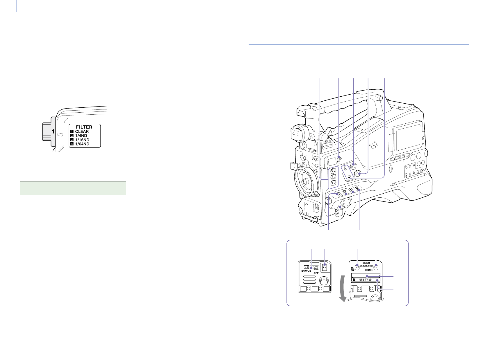
3. FILTER knob
Switches between four ND filters built into this
camcorder.
When this selector is used, the new setting
appears on the viewfinder screen for about three
seconds.
FILTER knob
setting
1 CLEAR
2 1/4 ND (attenuates light to
3 1/16 ND (attenuates light to
4 1/64 ND (attenuates light to
You can change a Maintenance menu setting so
that different white balance settings can be stored
for different FILTER knob positions. This allows you
to automatically obtain optimum white balance
for the current shooting conditions in linkage with
the filter selection.
“Adjusting the White Balance” (page 38)
ND filter
approximately 1/4)
approximately 1/16)
approximately 1/64)
5. AUTO W/B BAL (automatic white/black
balance adjustment) switch
Activates the automatic white/black balance
adjustment functions.
WHITE: Adjust the white balance automatically.
If the WHITE BAL switch (page 6) is set
to A or B, the white balance setting is stored
in the corresponding memory. If the WHITE
BAL switch is set to PRST, the automatic
white balance adjustment function does not
operate.
BLACK: Adjust the black set and black balance
automatically.
You can use the AUTO W/B BAL switch even when
the ATW (Auto Tracing White Balance) function is
operating.
If you push the switch to the WHITE side once
more during the automatic white balance
adjustment, the adjustment is canceled and
the white balance setting returns to the original
setting.
If you push the switch to the BLACK side once
more during the automatic black balance
adjustment, the adjustment is canceled and
the black balance setting returns to the original
setting.
6. MIC (microphone) LEVEL knob (page 42)
LCD Monitor Side (1)
21
3 4 5
6 7 8 9
10 12 12
11
13
14
4. MENU knob (page 88)
Page 6
1. Overview: Name and Function of Parts
000
6
1. ASSIGN. (assignable) 1/2/3 switches
You can assign a function using Operation
>Assignable Switch in the setup menu
(page 117).
The ASSIGN. 1/3 switches are provided with an
indicator to show whether a function is assigned
to the switch (ON) or not (OFF).
2. ONLINE button
When network client mode or the streaming
function is assigned to this button, press and hold
until the indicator is lit orange. Then, press the
button again, turning the indicator blue, to enable
network client mode or the streaming function.
To exit the enabled function, press and hold the
button until the indicator turns off.
The button can also be used as an assignable
switch when assigned with functions other than
those above (page 118).
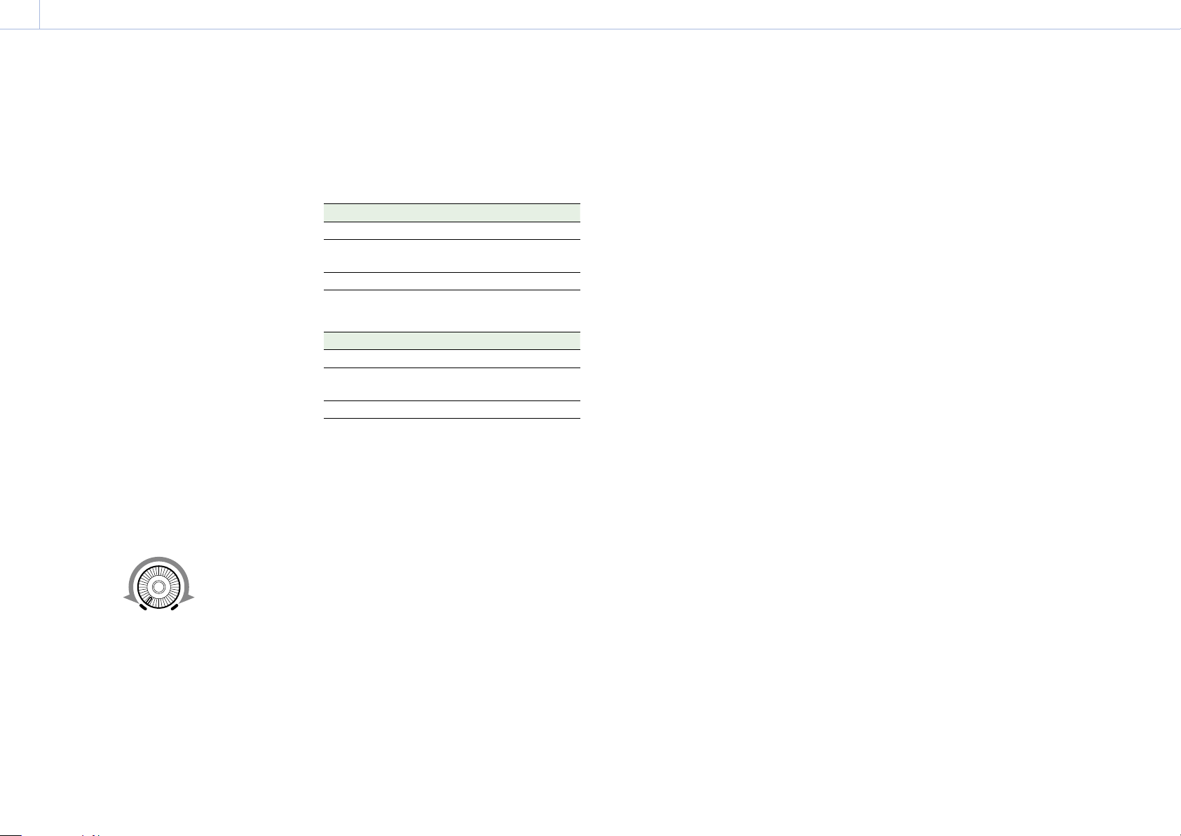
3. ALARM (alarm tone volume adjustment)
knob
Controls the volume of the warning tone that
is output via the built-in speaker or optional
earphones. When the knob is turned to the
minimum position, no sound can be heard.
However, if Maintenance >Audio >Min Alarm
Volume in the setup menu is set to [Set], the alarm
tone is audible even when this volume control is at
the minimum position.
ALARM
Minimum Maximum
4. MONITOR (monitor volume adjustment)
knob
Controls the volume of the sound other than the
warning tone that is output via the built-in speaker
or earphones. When the knob is turned to the
minimum position, no sound can be heard.
5. MONITOR (audio monitor selection) switches
By means of combinations of the two switches,
you can select audio that you want to hear
through the built-in speaker or earphones.
When the lower switch is set to CH-1/2
Upper switch Audio output
CH-1/CH-3 Channel 1 audio
MIX Channels 1 and 2 mixed audio
CH-2/CH-4 Channel 2 audio
(stereo)
a)
When the lower switch is set to CH-3/4
Upper switch Audio output
CH-1/CH-3 Channel 3 audio
MIX
CH-2/CH-4 Channel 4 audio
a) By connecting stereo headphones to the EARPHONE jack,
you can hear the audio in stereo. (Maintenance >Audio
>Headphone Out in the setup menu must be set to
Stereo.)
Channels 3 and 4 mixed audio
a)
(stereo)
6. ASSIGN. (assignable) 0 switch
You can assign a function using Operation
>Assignable Switch in the setup menu
(page 117).
Off is assigned to these switches when the
camcorder is shipped from the factory.
This is a momentary type switch. Each press of the
switch turns the function assigned to this switch
on or off.
7. GAIN switch
Switches the gain of the video amplifier to match
the lighting conditions during shooting. The gain
values corresponding to the L, M, and H settings
can be selected using Operation >Gain Switch in
the setup menu (page 96) (factory settings are
L=0 dB, M=6 dB, and H=12 dB).
When this switch is adjusted, the new setting
appears on the viewfinder screen for about three
seconds.
8. OUTPUT/DCC (output signal/dynamic
contrast control) switch
Switches the video signal output from the camera
module, between the following two.
BARS: Output the color bar signal.
CAM: Output the video signal being shot. When
this is selected, you can switch DCC
1)
on and
off.
1) DCC (Dynamic Contrast Control): Against a very bright
background with the iris opening adjusted to the subject,
objects in the background will be lost in the glare. The
DCC function will suppress the high intensity and restore
much of the lost detail. It is particularly effective for
shooting in the following cases.
Shooting people in the shade on a sunny day
Shooting a subject indoors, against a background
through a window
Any high contrast scene
9. WHITE BAL (white balance memory) switch
Controls adjustment of the white balance.
PRST: Adjust the color temperature to the preset
value (the factory default setting: 3200K). Use
this setting when you have no time to adjust
the white balance.
A or B: Recall the white balance adjustment
settings already stored in A or B. Push the
AUTO W/B BAL switch (page 5) to the
WHITE position to automatically adjust the
white balance and save the adjustment
settings in memory A or memory B.
1)
B (ATW
1) ATW (Auto Tracing White balance): The white balance
[Note]
It may not be possible to adjust to the appropriate colors
using ATW, depending on the lighting and subject
conditions.
):When this switch is set to B and
Operation >White Setting >White Switch
<B> is set to [ATW] in the setup menu, ATW is
activated.
You can use the AUTO W/B BAL switch even
when ATW is in use.
When this switch is adjusted, the new setting
appears on the viewfinder screen for about
three seconds.
of the picture being shot is adjusted automatically for
varying lighting conditions.
Examples:
When a single color dominates the subject, such as sky,
sea, ground, or flowers.
When the subject is under a light source of extremely
high or extremely low color temperature.
If execution of automatic tracing by the ATW
function takes an unacceptably long time or only
results in an inadequate effect, then execute the
AWB function.
10. Switch cover
Open this cover to use the MENU ON/OFF switch
or the MENU CANCEL/PRST/ESCAPE switch.
11. MENU ON/OFF switch
To use the switch, open the cover.
This switch is used to display the menu on the
viewfinder screen or the test signal screen. Each
time the switch is pushed down, the menu screen
is turned on and off.
The function of this switch is the same as that
of the MENU button in the thumbnail screen
operations section.
[Note]
It is not possible to turn off the menu screen by closing the
cover.
12. MENU CANCEL/PRST (preset) /ESCAPE switch
To use the switch, open the cover.
This switch has different functions depending on
whether or not a menu is displayed.
Use the switch in the following way when the
menu is displayed.
CANCEL/PRST: Pushing this switch up to this
position after a setting is changed in the
setup menu displays the message to confirm
whether the previous settings are canceled.
Pushing this switch up to this position again
cancels the previous settings.
Pushing this switch up to this position before a
setting is changed in the setup menu or after a
setting change is canceled in the setup menu
displays the message to confirm whether the
setting is reset to the initial value. Pushing
this switch up to this position again resets the
Page 7
1. Overview: Name and Function of Parts
000
7
settings to the initial value.
ESCAPE: Use this switch when the menu page,
which has a hierarchical structure, is opened.
Each time the switch is pushed to this position,
the page returns to one stage higher in the
hierarchy.
Use the switch in the following way when the
menu is not displayed.
CANCEL/PRST: Each time this switch is pushed
upward, a window to confirm the menu
settings and status of the camcorder appears
on the viewfinder screen (page 13). The
window consists of several pages, which are
switched each time the switch is pushed
upward.
ESCAPE: To clear the page, push this switch down
to the OFF position.
13. UTILITY SD card slot
Insert an SD card for saving camcorder settings.
14. ACCESS indicator
Lights up orange when the SD card is being
accessed.
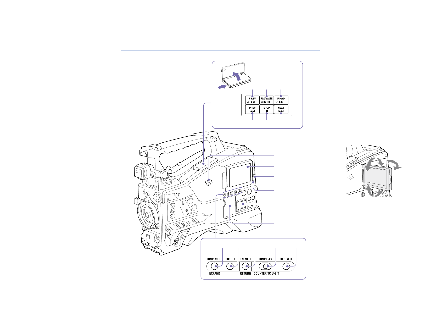
LCD Monitor Side (2)
[1]
[2]
7 8 9
10
11 12
1
2
3
4
1. Built-in speaker
The speaker can be used to monitor E-E
during recording, and playback sound during
playback. The speaker also sounds alarms to
reinforce visual warnings (page 137).
If you connect earphones to the EARPHONE jack,
the speaker output is suppressed automatically.
1) E-E: Abbreviation of “Electric-to-Electric.” In E-E mode,
video and audio signals input to the camcorder are
output after passing through internal electric circuits only.
This can be used to check input signals.
1)
sound
2. LCD monitor
Displays remaining battery capacity, remaining
media capacity, audio levels, time data, and so on.
It also allows you to check camera and playback
pictures (page 13).
You can adjust the position and angle of the LCD
monitor.
13
14 15
5
6
16 17
3. WARNING indicator
Lights up or flashes when an abnormality occurs
(page 137).
4. ACCESS indicator
Lights up in blue when data is written to or read
from the recording media.
5. Audio control section (page 9)
6. Thumbnail screen operation section
(page 9)
7. F REV (fast reverse) button and indicator
This plays back at high speed in the reverse
direction. The playback speed changes in the order
×4 ×15 ×24 with each press of the button.
Page 8

1. Overview: Name and Function of Parts
000
8
The indicator lights during high-speed playback in
the reverse direction.
8. PLAY/PAUSE button and indicator
Press this button to view playback video images
using the viewfinder screen or the LCD monitor.
The indicator lights during playback.
Press this button again during playback to pause,
outputting a still image. At this time the indicator
flashes at a rate of once per second.
Pressing the F REV or F FWD button during
playback or pause starts high speed playback in
the forward or reverse direction.
9. F FWD (fast forward) button and indicator
This plays back at high speed in the forward
direction. The playback speed changes in the order
×4 ×15 ×24 with each press of the button.
The indicator lights during high-speed playback in
the forward direction.
10. PREV (previous) button
This jumps to the first frame of the current clip.
If you press this together with the F REV button,
the jump is to the first frame of the first recorded
clip on the recording media.
If you press this button twice in rapid succession,
the jump is to the first frame of the preceding
clip (or the first frame of the current clip when no
preceding clips exist).
11. STOP button
Press this button to stop playback.
12. NEXT button
This jumps to the first frame of the next clip.
If you press this together with the F FWD button,
the jump is to the last frame of the last recorded
clip on the recording media.
13. DISP SEL (display selection)/EXPAND
(expand function) button
With each press of this button, the display in the
LCD monitor changes as follows.
Display indication Description
Video with
superimposed
information (CHAR)
Video without
superimposed
information (MONI)
Status display
(STATUS)
The LCD monitor displays
the same text information as
the viewfinder.
Only the video appears.
Counter indications,
warnings, audio levels, and
similar information appear.
No video image appears.
The EXPAND button function will be supported in
a future upgrade.
14. HOLD (display hold) button
Pressing this button instantly freezes the time
data displayed in the LCD monitor. (The timecode
generator continues running.) Pressing this button
again releases the hold.
For details about the time data display, see page 13.
15. RESET/RETURN button
Resets the value shown in the time data display in
the LCD monitor. According to the settings of the
PRESET/REGEN/CLOCK switch (page 9) and the
F-RUN/SET/R-RUN switch (page 9), this button
resets the display as follows.
Switch settings RESET/RETURN button
operation
DISPLAY switch:
COUNTER
DISPLAY switch:
TC
PRESET/REGEN/
CLOCK switch:
PRESET
F-RUN/SET/R-RUN
switch:
SET
Reset counter to 00:00:00:00.
Reset timecode to
00:00:00:00.
Switch settings RESET/RETURN button
operation
DISPLAY switch:
U-BIT
PRESET/REGEN/
CLOCK switch:
PRESET
F-RUN/SET/R-RUN
switch:
SET
a) Of the timecode bits for every frame recorded on the
media, those bits which can be used to record useful
information for the user such as scene number, shooting
place, etc.
“Setting Time Data” (page 44)
Reset user bits data
00:00:00:00.
a)
to
This button returns to the previous screen when
pressed during thumbnail screen display or
essence mark thumbnail screen display.
16. DISPLAY switch
This cycles the data displayed in the time data
display in the LCD monitor through the sequence
COUNTER, TC, and U-BIT (page 13).
COUNTER: Display recording/playback duration
counter.
TC: Display timecode.
U-BIT: Display user bits data.
17. BRIGHT (brightness) button
Switches the brightness of the LCD monitor
backlight.
Each press of the button selects the next setting in
the order shown in the following table. If you press
the button with the LCD monitor off, the LCD
backlight comes on in the H state.
Setting LCD monitor backlight
H High (select this to view the LCD monitor
outdoors in the daytime)
M Brightness between H and L
L Low (select this to view the LCD monitor
indoors or outdoors at night)
OFF Off (the display is also off)
Page 9
1. Overview: Name and Function of Parts
000
9
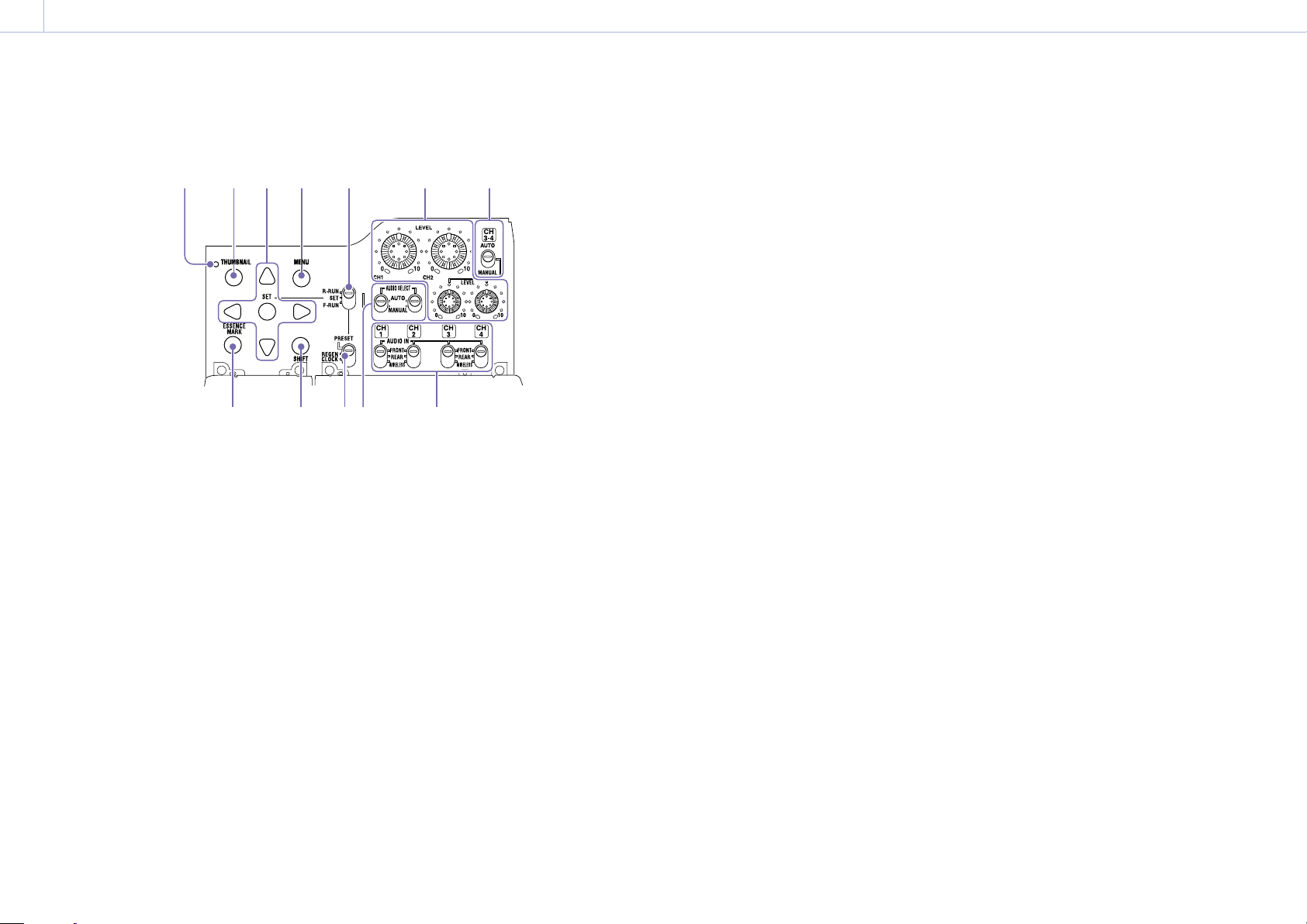
Thumbnail screen operations section and audio control section
1
1. Thumbnail indicator
This lights when the thumbnail screen is displayed.
2. THUMBNAIL button
Press this button to display the thumbnail
screen (page 79) and to carry out a thumbnail
operation.
Press once more to return to the original display.
3. SET button and arrow buttons
Use these buttons to make timecode and user bit
settings, and for thumbnail screen operations.
When the menu is displayed, press this button to
select an item or to confirm the setting change.
4. MENU button
Each press of this button turns the setup menu
display on and off.
The function of this button is the same as that of
the MENU ON/OFF switch.
5. F-RUN/SET/R-RUN (free run/set/recording
run) switch
Selects the operating mode of the internal
timecode generator. The operating mode is set
as explained below, depending on the position of
the switch.
2 3
8
5
9 1011 12
F-RUN: Timecode keeps advancing, regardless of
whether the camcorder is recording. Use this
setting when synchronizing the timecode with
external timecode.
SET: Sets the timecode or user bits.
R-RUN: Timecode advances only during recording.
Use this setting to have a consecutive
timecode on the recording media.
“Setting the Timecode” (page 44)
“Setting the User Bits” (page 44)
6. LEVEL CH1/CH2/CH3/CH4 (audio channel
1/2/3/4 recording level) knobs
Adjust the audio levels to be recorded on channels
1, 2, 3, and 4 when the AUDIO SELECT CH1/CH2
and AUDIO SELECT CH 3-4 switches are set to
MANUAL.
7. AUDIO SELECT CH 3-4 (audio channel 3/4
adjustment method selection) switches
Select the audio level adjustment method for
audio channels 3 and 4.
AUTO: Automatic adjustment
MANUAL: Manual adjustment
6
8. ESSENCE MARK button
By pressing this button when a thumbnail display
is on the screen, you can view the following
74
thumbnail displays of the essence-marked frames
of the selected clip, depending on the item
selected in a list displayed on the screen.
All: Thumbnail display of all frames marked with
essence marks.
Rec Start: Thumbnail display of frames marked
with Rec Start marks and of the first frames of
clips (when the first frames are not marked
with Rec Start marks).
Shot Mark1: Thumbnail display of the frames
marked with Shot Mark 1.
Shot Mark2: Thumbnail display of the frames
marked with Shot Mark 2.
You can also select Shot Mark 0 and Shot Mark 3 to
Shot Mark 9.
If a clip is recorded using planning metadata that
defines names for shot mark 0 to shot mark 9, the
selection options in the list are displayed by the
defined names.
12. AUDIO IN CH1/CH2/CH3/CH4 (audio channel
1/2/3/4 input selection) switches
Select the audio input signals to be recorded on
audio channels 1, 2, 3 and 4.
FRONT: Audio input signals from the microphone
connected to the MIC IN connector
REAR: Audio input signals from an audio device
connected to the AUDIO IN CH-1/CH-2
connectors
WIRELESS: Audio input signals from the UHF
portable tuner if it is attached
9. SHIFT button
Use this in combination with other buttons.
10. PRESET/REGEN (regeneration)/CLOCK switch
Selects the type of timecode to record.
PRESET: Record new timecode on the media.
REGEN: Record timecode continuous with the
existing timecode recorded on the media.
Regardless of the setting of the F-RUN/SET/R-
RUN switch, the camcorder operates in R-RUN
mode.
CLOCK: Record timecode synchronized to the
internal clock. Regardless of the setting of
the F-RUN/SET/R-RUN switch, the camcorder
operates in F-RUN mode.
11. AUDIO SELECT CH1/CH2 (audio channel 1/2
adjustment method selection) switches
Select the audio level adjustment method for
audio channels 1 and 2.
AUTO: Automatic adjustment
MANUAL: Manual adjustment
Page 10

1. Overview: Name and Function of Parts
000
10
Handle and Memory Card Slot Side
SxS memory card slots (page 27)
10
11 12
13 14
1. ASSIGNABLE 4/5 switches
You can assign a function using Operation
>Assignable Switch in the setup menu
(page 118).
Off is assigned to these switches when the
[Note]
Do not grasp this part of the camcorder when the GPS
function is in use.
3. PC connector
Used to put this camcorder into USB connection
1
456
23
mode and use it as an external storage device
for a computer. When a computer is connected
to this connector, every memory card inserted
in the camcorder is recognized as a drive on the
computer.
4. External device connector
Connect to a PSZ-HA50 Portable Storage HDD
(option), PSZ-SA25 Portable Storage SSD (option),
a general-purpose external USB HDD, or USB flash
drive to copy clips from the recording media
inserted in an SxS card slot of the camcorder to
7
8
9
USB media.
[Note]
This connector should be used only for connecting the type
of devices above. It cannot be used for connecting a USB
hub or other devices.
5. USB wireless LAN module connector
Connect to an IFU-WLM3 USB Wireless LAN
Module (supplied), CBK-WA02 Wireless LAN
Adaptor (option), or combination of CBK-NA1
Network Adaptor Kit (option) and modem (option)
to enable communications with wireless LAN
devices and networks.
“Connecting Devices using Wireless LAN” (page 59)
“Connecting to the Internet” (page 63)
6. PROXY SD card slot (page 53)
Insert an SD card for recording proxy data.
7. (NFC) mark
A built-in NFC antenna is provided.
8. SLOT SELECT (SxS memory card select)
camcorder is shipped from the factory.
2. GPS module
Contains a built-in GPS module.
“Obtaining Location Information (GPS)” (page 57)
button
When SxS memory cards are loaded in both card
slots A and B, press this button to select the card
you want to use (page 28).
9. Network connector
Connects to a network via a wired LAN connection
using a LAN cable (sold separately).
[CAUTION]
For safety, do not connect the connector for peripheral
device wiring that might have excessive voltage to this
port.
Follow the instructions for this port.
When you connect the LAN cable of the unit to peripheral
device, use a shielded-type cable to prevent malfunction
due to radiation noise.
“Connecting to the Internet” (page 63)
10. HDMI connector
Connect an HDMI device, such as a monitor or
recording unit, to output HD or SD HDMI video
and audio signals.
[Note]
4K (QFHD) output is not supported.
11. GENLOCK IN (genlock signal input)
connector (BNC type)
This connector inputs a reference signal when the
camcorder is to be genlocked or when timecode
is to be synchronized with external equipment.
The supported reference signals vary depending
on the current system frequency as shown in the
following table.
System frequency Supported reference signals
59.94i 1080/59.94i, 480/59.94i
59.94P 1080/59.94i, 480/59.94i
50i 1080/50i, 576/50i
50P 1080/50i, 576/50i
29.97P 1080/59.94i, 480/59.94i
25P 1080/50i, 576/50i
23.98P 1080/23.98PsF
12. TC IN (timecode input) connector (BNC type)
To apply an external lock to the timecode of the
camcorder, input the reference timecode.
“Setting the Timecode” (page 44)
13. VIDEO OUT connector (BNC type)
Outputs video signals for monitoring.
Page 11
1. Overview: Name and Function of Parts
1
000
11
14. TC OUT (timecode output) connector (BNC
type)
To lock the timecode of an external VTR to
the timecode of this camcorder, connect this
connector to the external VTR’s timecode input
connector.
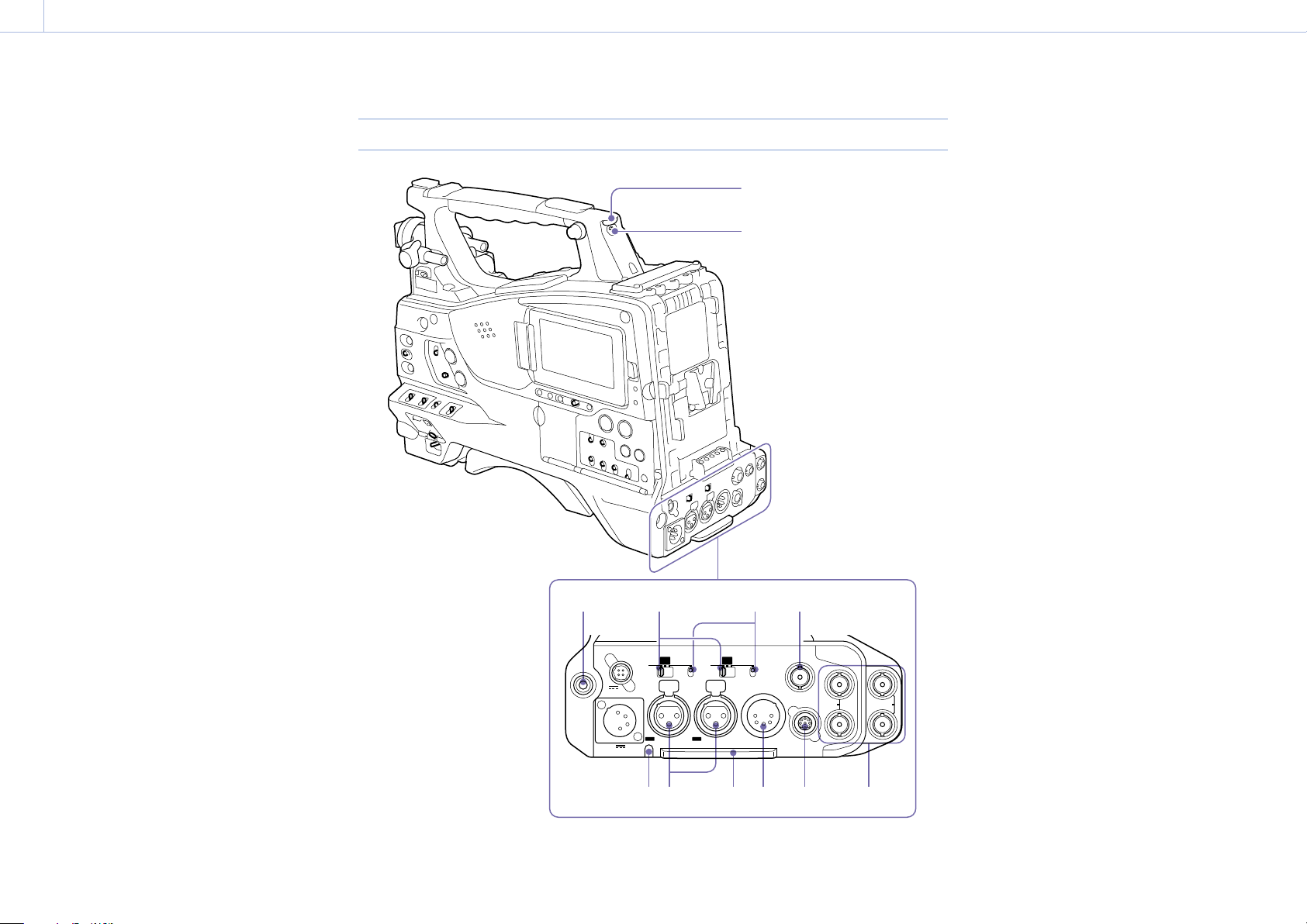
Tally Indicator and Connector Section
12V 1.8A
43
AES/
EBU
LINE
CH1
1/2
1 8 9 10 117
+48V
MIC
OFF
CH2
3/4
AUDIO IN
1. TALLY (back tally) indicator (red)
Lights up during recording. It will not light if the
TALLY switch is set to OFF. It also flashes when the
WARNING indicator operates. The tally indicator on
the front of the viewfinder and the REC indication
on the viewfinder screen light or flash in the same
2
manner.
“Error/Warning System” (page 137)
2. TALLY switch
Set to ON to activate the TALLY indicator function.
3. EARPHONE jack (stereo, mini jack)
You can monitor the E-E sound during recording
and playback sound during playback. When an
alarm is indicated, you can hear the alarm sound
through the earphone. Plugging an earphone into
the jack automatically cuts off the built-in speaker.
You can select monaural or stereo using
Maintenance >Audio >Headphone Out in the
setup menu.
[Note]
Use monaural (2-pole) or stereo (3-pole) type earphones. Use
of other earphones may damage the camcorder.
4. AUDIO IN selector switch
Select the audio source you connect to the AUDIO
IN CH1/CH2 connectors.
LINE: When connecting a stereo amplifier or other
65
external audio signal source
AES/EBU: When connecting an external digital
audio signal source
AES/
EBU
MIC
LINE
+48V
OFF
SDI IN
1
SDI OUT
REMOTEAUDIO OUT
3
2
SDI OUT
4
MIC: When connecting a microphone.
5. +48V/OFF (+48V external power source on/
off) switch
Switch between the following settings, according
to the microphone used for audio input.
+48V: Microphone requiring external power
source (phantom power)
OFF: Microphone using internal power source or
not requiring a power source
6. SDI IN (SDI input) connector (BNC type)
Connector used when connecting an external SDI
signal source to the camcorder.
Page 12

1. Overview: Name and Function of Parts
000
12
7. AUDIO IN CH-1/CH-2 (audio channel 1 and
channel 2 input) connectors (XLR type, 3-pin,
female)
Connect to audio equipment or a microphone.
8. Bottom cover
This is provided for protecting the cables
connected to the connectors on the rear panel.
By loosening the screws which retain the cover to
the bottom of the camcorder, you can adjust the
position of the cover depending on the size and
shape of the microphone or audio cable plugs.
After adjusting the position, tighten the screws to
secure the cover.
9. AUDIO OUT connector (XLR type, 5-pin,
male)
Outputs the audio signals recorded on audio
channels 1 and 2 or audio channels 3 and 4.
The audio signals are selected by the MONITOR
switch.
10. REMOTE connector (8-pin)
Connect a remote control unit to control the
camcorder remotely.
[Note]
Before connecting/disconnecting the Remote Control Unit
to/from the camcorder, be sure to turn off the camcorder
POWER switch.
11. SDI OUT 1/2/3/4 connectors (BNC type)
Outputs a 3G/HD SDI or SD SDI signal (with
embedded audio). The output from this connector
can be turned on/off using Operation >Input/
Output >SDI Out1/3 Output or SDI Out2/4 Output
in the setup menu.
Page 13
1. Overview
1 2 3 4 5
000
13
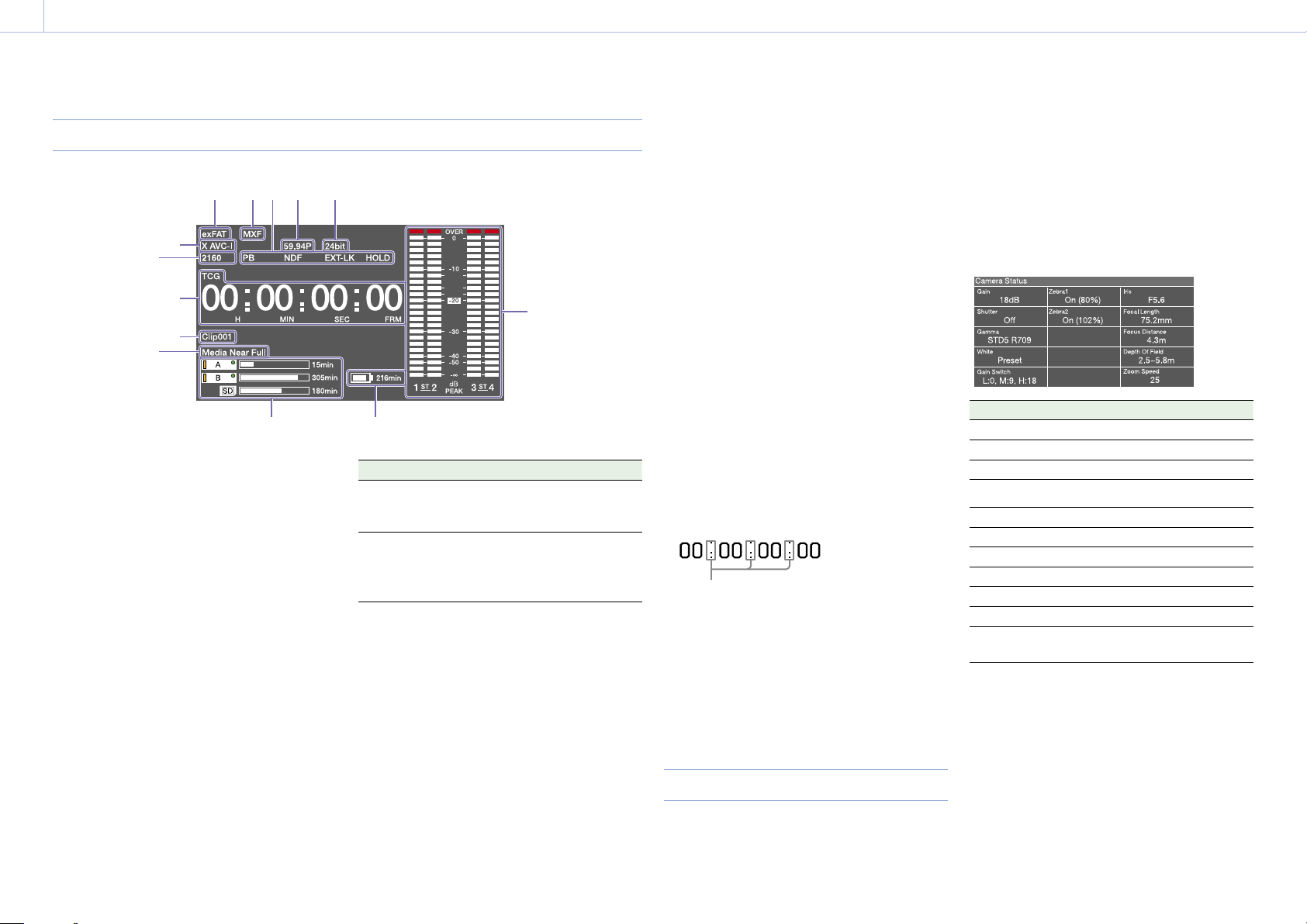
Screen Display
Information Screen
13
12
11
10
9
1. File system indicator
2. File format indicator
3. Status display
PB: Appears during media playback.
NDF: Appears when non-drop-frame timecode is
selected.
EXT-LK: Appears when the internal timecode
generator is locked to an external signal input
to the TC IN (timecode input) connector.
HOLD: Appears when the operation mode of the
internal timecode generator is set to R-RUN
and stopped.
4. System frequency indicator
Indicates the system frequency of video being
currently played or recorded.
5. Audio format indicator
Indicates the audio recording format or the audio
format of clip being currently played.
6
78
Indicator Recording format
16bit HD420 HQ
DVCAM
MPEG IMX 50
24bit HD422 50
MPEG IMX 50
XAVC Intra
XAVC Long
6. Audio level meters
Indicates the audio recording or playback levels of
channels 1 to 4.
7. Remaining battery capacity indicator
Displays the battery remaining capacity icon and
the remaining recording time.
8. Remaining media capacity indicator
Shows bar segments indicating the remaining
capacity of recording media in the slots.
9. Warning indicator area
Displays warnings when trouble with recording
occurs.
For details, see “Error/Warning System” (page 137).
10. Clip name display
Displays the name of the clip currently recording
when recording, or displays the name of the next
clip to be recorded during recording standby.
11. Time data display
Switches displays of duration, timecode, and
user bits data, depending on the position of the
DISPLAY switch.
Displays the type of data currently shown in the
time data display, as follows.
TCG: Recorded timecode
TCR: Playback timecode
UBG: Recorded user bits
UBR; Playback user bits
CNT: Counter
DUR: Duration
CLK: Time display (when the PRESET/REGEN/
CLOCK switch is set to CLOCK)
When the HOLD button is pressed to hold the
timecode value, the timecode is displayed in the
format shown below. When the HOLD button is
pressed again to release the hold, the timecode is
displayed in the normal format.
The three dots indicate that the timecode and
counter progress are in hold mode.
12. Resolution indicator
Indicates the resolution of the output video.
13. Recording format indicator
Indicates the current recording format or the
recording format of clip being currently played.
Status Screens
The status screens allow you to check camcorder
settings and various types of status information.
When no menu is displayed, push the MENU
CANCEL/PRST/ESCAPE switch up to the CANCEL/
PRST position to display the status screen. Each
push selects the next status screen.
The following status screens can be displayed.
Camera Status screen
Displays settings and status information related to
shooting.
Display item Description
Gain Gain level in dB units
Shutter Electronic shutter status
Gamma Gamma category and curve
White White balance mode setting
Gain Switch GAIN switch status
Zebra Zebra pattern status
Iris Iris f-stop value
Focal Length Focal length
Focus Distance Focus distance
Depth Of Field Depth of field
Zoom Speed Zoom speed configured for the
lens ZOOM button
Page 14
1. Overview: Screen Display
000
14
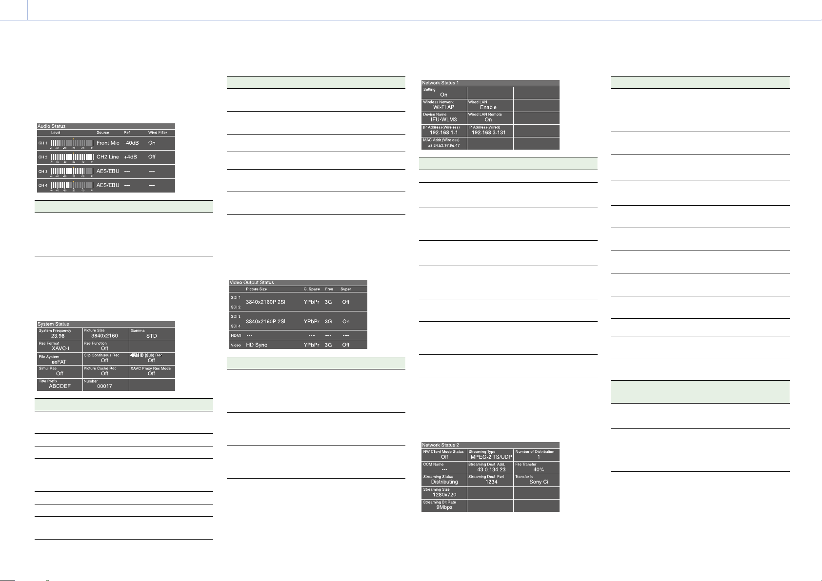
Audio Status screen
Displays settings and status information related to
audio input and output.
Display item Description
CH 1/CH 2/CH
3/CH 4
Audio level, input source,
reference input level, and wind
noise reduction filter settings for
each channel
System Status screen
Displays settings and status information related to
recording.
Display item Description
System
Frequency
File System File system
Rec Format Recording format
Clip
Continuous
Rec
Title Prefix Clip name prefix
Picture Size Picture size
Simul Rec 2-slot Simul Rec function on/off
System frequency
Clip Continuous Rec function on/
off setting
setting
Display item Description
Rec Function Enabled special recording format
and settings
Picture Cache
Rec
Number Clip name suffix
Gamma Gamma category in use
4K&HD (Sub)
Rec
XAVC Proxy Rec
Mode
Picture Cache Rec function on/off
setting
1-slot Simul Rec function on/off
setting
Proxy data recording function on/
off setting
Video Output Status screen
Displays settings and status information related to
video output.
Display item Description
SDI SDI OUT connector output
settings (output picture size,
output form, output rate,
superimposition)
HDMI HDMI connector output settings
(output picture size, output form,
output rate, superimposition)
Video VIDEO OUT connector output
settings (output picture size,
superimposition)
Network Status 1 screen
The Network Status 1 screen displays settings and
status information related to the network.
Display item Description
Setting Network setting status
Wireless
Network
Device Name Name of device attached to the
IP Address
(Wireless)
MAC Addr.
(Wireless)
Wired LAN Wired LAN network connection
Wired LAN
Remote
IP Address
(Wired)
Wireless network setting status
USB wireless LAN module
connector
IP address of wireless LAN
connection
MAC address of device attached
the USB wireless LAN module
connector
status
Remote control enabled/disabled
state when connected using a
LAN cable
IP address of wired LAN
connection
Network Status 2 screen
The Network Status 2 screen displays settings and
status information related to streaming.
Display item Description
NW Client
Mode Status
CCM Name Name of the connected CCM
Streaming
Status
Streaming Size Picture size of the currently
Streaming Bit
Rate
Streaming Type Type of the currently selected
Streaming
Dest. Add.
Streaming
Dest. Port
Number of
Distribution
File Transfer File transfer progress status
Transfer to: Server name of file transfer
Network client mode status
Status
display
Off CCM not
Connected CCM
Network client mode status
For details about the status, see
“Network client mode status”
(page 14).
when using network client mode
Streaming distribution status
selected streaming setting
Bit rate of the currently selected
streaming setting
streaming setting
Streaming destination address
Streaming destination port
Number of streaming distribution
destinations
destination
State Description
Network client mode is
connected
connected
off.
Network client mode is
on, CCM is connected,
and CCM control is
enabled.
Page 15
1. Overview: Screen Display
000
15
Status
display
Connecting
Awaiting
Address
Error
Auth. Failed CCM user
No Inet
Access
Cert. not
Valid
State Description
Connecting to
CCM
(disconnected)
CCM
connection
standby
CCM
address
error
name/
password
error
Internet
connection
error
CCM
certification
not valid
error
Attempting to connect
to CCM (or
disconnecting). Wait
until connection
(disconnection) is
successful. If the status
does not change from
“Connecting,” the CCM
address setting may be
incorrect. Check that the
address is set correctly.
Network client mode is
on, but the network
setting is off. Enable the
network setting to
connect to the CCM.
The host name or IP
address of the CCM to
connect may be
incorrect. Check that the
setting is correct.
The user name or
password used to
connect to the CCM
may be incorrect. Check
that the setting is
correct.
Cannot connect to the
network. The network
settings may be
incorrect. Check the
network settings.
The CCM certificate is
not valid. The date
setting may be invalid.
Check the date setting.
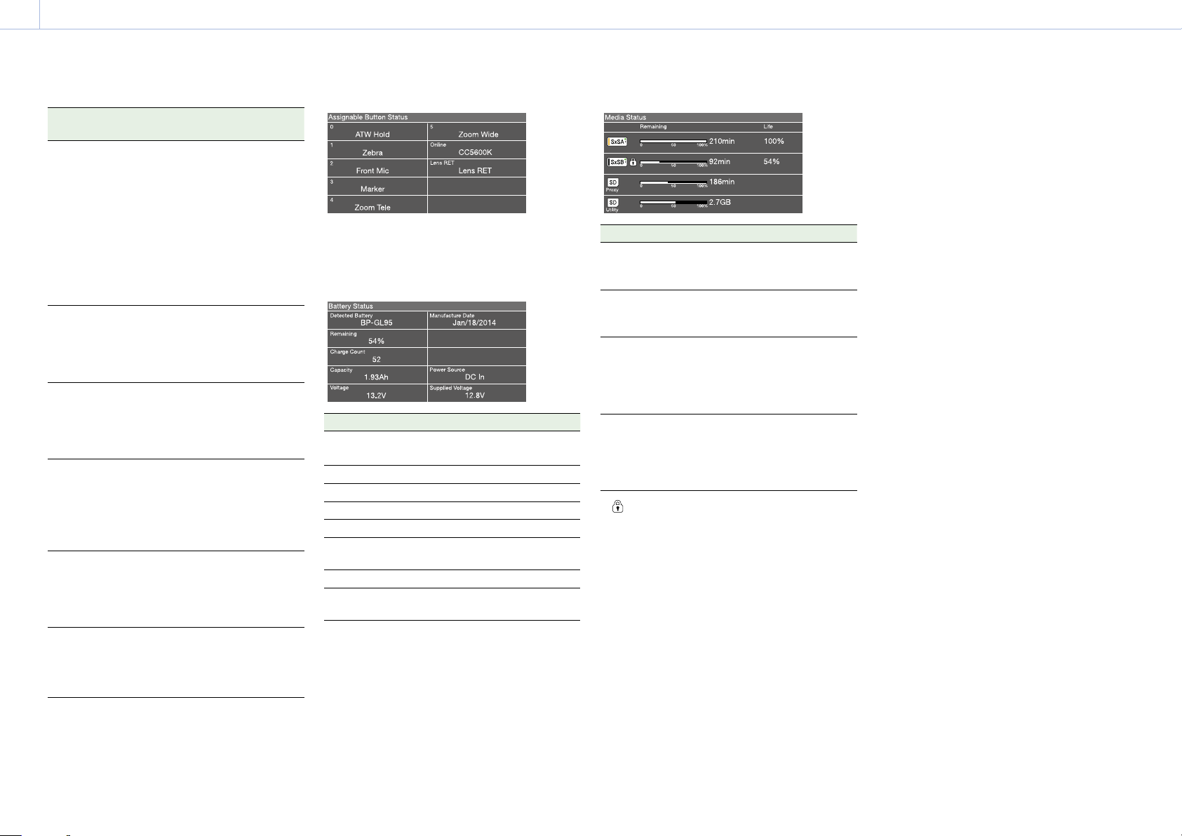
Battery Status screen
Displays the status of the battery attached to the
camcorder.
Display item Description
Detected
Battery
Remaining Remaining capacity (%)
Charge Count Number of recharges
Capacity Remaining capacity (Ah)
Voltage Voltage
Manufacture
Date
Power Source Power supply source
Supplied
Voltage
Detected type of the battery
Date of battery manufacture
Supplied power source voltage
Media Status screen
Displays the status of the recording media.
Display item Description
SxSA Remaining capacity (bar graph
and remaining time display) and
media life of media in slot A
SxSB Remaining capacity (bar graph
and remaining time display) and
media life of media in slot B
SD Proxy Remaining capacity (bar graph
and remaining time display) and
media life (displayed only if
available) of media in PROXY SD
card slot
SD Utility Remaining capacity (bar graph
and remaining capacity) and
media life (displayed only if
available) of media in UTILITY SD
card slot
A mark is displayed if the media is protected.
Assignable Button Status screen
Displays the names of functions assigned to
assignable switches.
Page 16
1. Overview: Screen Display
000
16
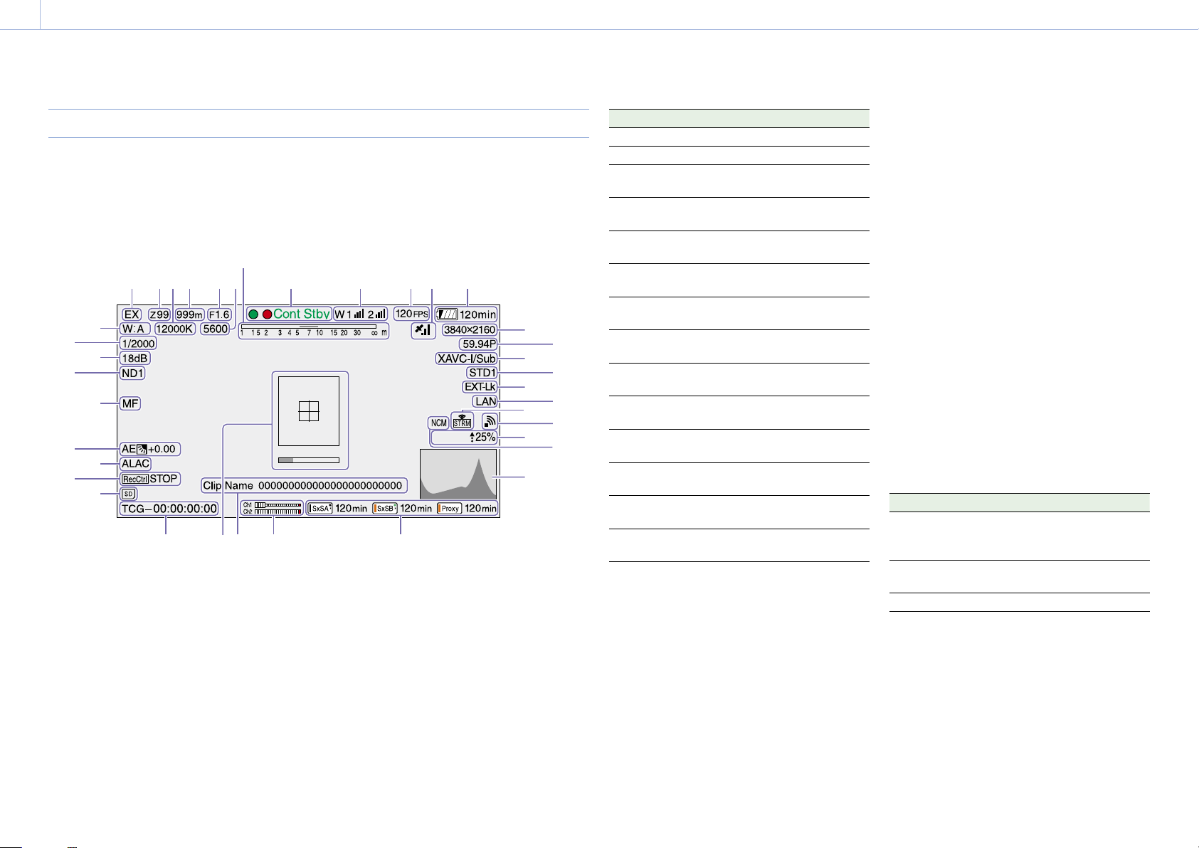
Viewfinder Screen
The viewfinder screen displays images during
shooting (recording or recording standby)
and playback with camcorder information
superimposed on the display.
You can toggle the display of information on/off
7
1 2 5 6 843
37
36
35
34
33
32
31
30
29
2528
2627
1. Extender indicator
“EX” appears when the lens extender function is
ON.
2. Zoom position indicator (with lens mounted)
Displays the zoom position of the zoom lens in the
range 0 to 99.
3. Color temperature indicator
Displays the color temperature of the white
balance.
4. Focus position indicator (with lens mounted)
Displays the focus position as a distance to the
subject (unit: meters).
using the DISPLAY switch.
The information to display is linked to the settings
in Operation >Super Impose in the setup menu,
and the settings of the corresponding switches.
9 10 11 12
13
14
15
16
17
18
19
Proxy
21
20
22
23
24
5. Iris position indicator (with lens mounted)
Displays the iris position setting.
6. Electric color temperature filter indicator
Appears when the CC5600K function is on.
7. Depth of field indicator (serial lens mounted)
Displays the depth of field using a bar. The units
for display are set using Operation >Display On/Off
>Lens Info in the setup menu, and can be set to
meters or feet.
8. Recording mode indicator
Displays the following recording operation states
of the camcorder.
Indicator Meaning
Rec
Stby Recording standby
Cont Rec
Cont Stby Recording standby in clip continuous
S&Q Rec
S&Q Stby Recording standby in Slow & Quick
Rec
Cache
Int Rec
Int Stby Recording standby in Interval Rec
Int Stby
Sml Rec
Sml Stby Recording standby in Simul Rec
CALL Call received from external
Green tally is displayed when the camcorder is in
the following states.
Maintenance >Camera Config >HD-SDI Remote
I/F is set to Green Tally in the setup menu and a
recording control signal is output from the SDI
OUT connector.
Green tally signal received (when a camera
adaptor is mounted on the camcorder and a
camera extension unit is connected)
During recording
Clip continuous recording in
progress
recording mode
Recording in progress in Slow &
Quick Motion mode
Motion mode
Recording in Picture Cache Rec
mode
Recording standby in Picture Cache
Rec mode
Recording in progress in Interval Rec
mode
mode
Recording paused in Interval Rec
mode (during pause intervals)
Recording in progress in Simul Rec
mode
mode
connected device
9. Wireless receiver function indicator
Displays “W” when a slot-in receiver is attached to
the camcorder, and displays the reception level
for each channel that can be used by the receiver
(1ch, 2ch, or 4ch).
Normal: Displays the strength of the received
signal level by the number of white segment
indicators.
Analog receiver muting/Digital receiver error rate
warning: Displays the strength of the received
signal level by the number of gray segment
indicators.
If the received level exceeds the peak: Displays “P”
in place of the indicator.
If the transmitter is in power-save mode: “S” is
displayed.
Receiver battery is low: The corresponding channel
number and indicators flash.
1) When using the DWR-S02D
1)
1)
10. S&Q Motion (Slow & Quick) frame rate
indicator
Displays the shooting frame rate when the
camcorder is set to Slow & Quick Motion recording
mode.
11. GPS indicator (page 57)
12. Battery capacity/voltage display
Displays the following indicators according to the
type of battery power source.
Battery type Indicator
Info battery Battery remaining capacity
icon and remaining recording
time
Anton/Bauer
battery
Other batteries Input voltage
Remaining battery capacity (%
indicator)
13. Recording format (picture size) indicator
Displays the picture size of clips recorded onto SxS
memory cards.
14. Recording format (system frequency and
scan method) indicator
Displays the currently configured camcorder
system frequency and the recording format scan
method.
Page 17
1. Overview: Screen Display
000
17
15. Recording format (codec) indicator / 1-slot
Simul Rec indicator
Displays the format name of clips recorded onto
SxS memory cards.
“/Sub” is displayed in 1-slot Simul Rec mode
(page 51).
16. Gamma indicator
Display the gamma setting.
Menu settings Indicator
Operation
>Display
On/Off
>Gamma
Off – – – –
On Off – – Gamma
On On User User 1 User 1
Paint >Gamma setting
Gamma
On STD STD1 DVW STD1
Gamma
Category
HG HG1
Gamma
Select
STD2 x4.5 STD2
STD3 x3.5 STD3
STD4 240M STD4
STD5 R709 STD5
STD6 x5.0 STD6
3250G36
HG2
4600G30
HG3
3259G40
HG4
4609G33
User 2 User 2
User 3 User 3
User 4 User 4
User 5 User 5
Off
HG1
HG2
HG3
HG4
17. Timecode external lock indicator
Displays timecode lock when the timecode is
input from an external source.
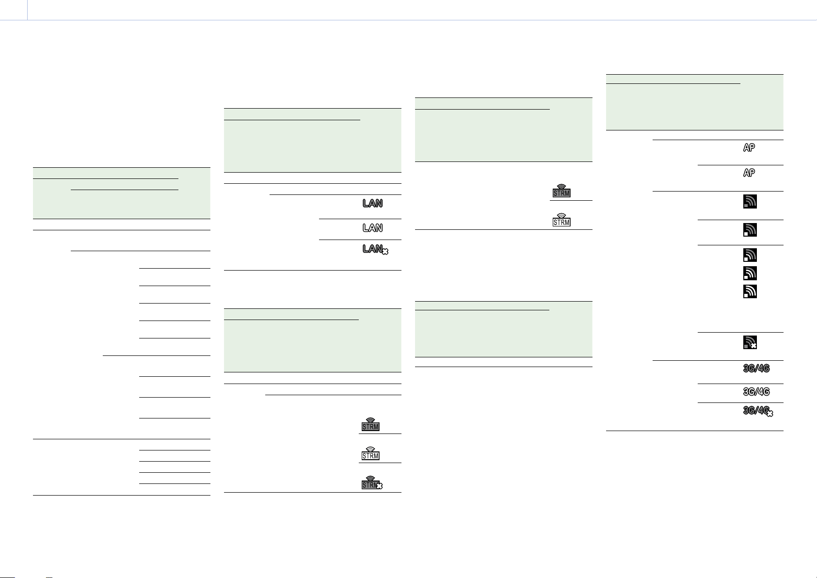
18. Wired LAN connection status
Displays the wired LAN network setting and
connection status using icons.
State Icon
Operation
>Display On/
Off >Network
Condition
Off – – –
On Disable – –
Maintenance
>Network
>Wired LAN
Enable Connecting
Network
connection
status
to LAN
Connected
to LAN
LAN
connection
error
(flashing)
19. Streaming indicator
Displays the status of streaming using icons.
State Streaming
Operation
>Display On/
Off
>Streaming
Status
Off – – –
On Off Off –
Maintenance
>Streaming
>Setting
On Off Not
Maintenance
>Network
Client Mode
>Setting
state/Icon
streaming
Streaming
Error
The following icons are displayed when streaming
from a CCM.
State Streaming
Operation
>Display On/
Off
>Streaming
Status
On Off On Not
Maintenance
>Streaming
>Setting
Maintenance
>Network
Client Mode
>Setting
state/Icon
streaming
Streaming
[Note]
Icons are not displayed before streaming starts.
20. Wireless network status indicator
Displays the network setting and connection
status using icons.
State Icon
Operation
>Display On/
Off >Network
Condition
Off – – –
Maintenance
>Network
>Wireless
Network
Network
connection
status
State Icon
Operation
>Display On/
Off >Network
Condition
On Off – –
Maintenance
>Network
>Wireless
Network
Wi-Fi Access
Point
Wi-Fi Station Connecting
Modem Connecting
Network
connection
status
Connecting
using Wi-Fi
Wi-Fi standby
(connected)
using Wi-Fi
Access point
search
Access point
connection
Access point
connection
error
using 3G/4G
Connected
using 3G/4G
3G/4G
connection
error
1)
1)
1)
(flashing)
(flashing)
Icon varies
with signal
strength.
(flashing)
1) This icon is displayed in the following cases.
When a device is not attached
When a device is attached with different settings
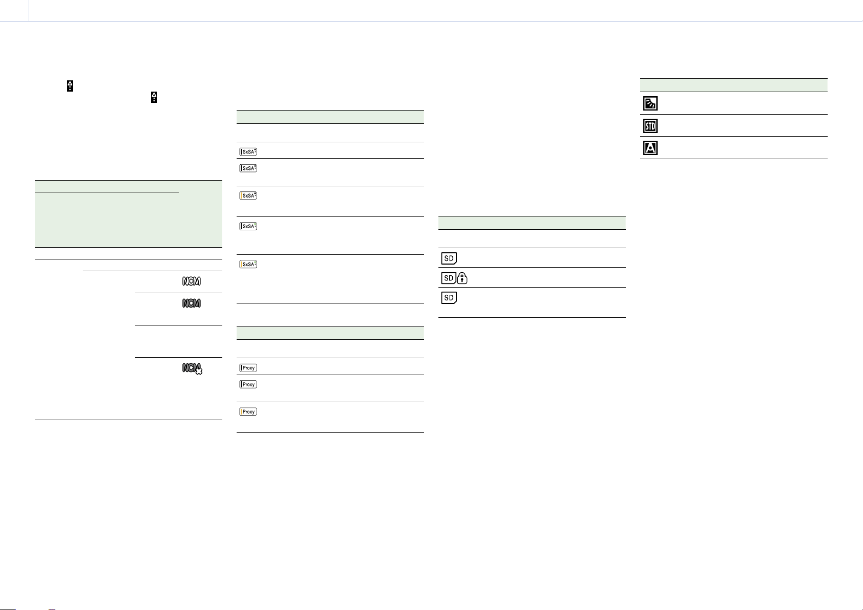
21. Proxy indicator
Displays “Proxy” when proxy recording is on
(Operation >XAVC Proxy Rec Mode >Setting in
the setup menu is set to On). During setup, “Proxy”
blinks. “Proxy Rec” is displayed during proxy
recording.
Page 18
1. Overview: Screen Display
000
18
Displays
transfer. When transfer finishes,
and transfer rate (%) during proxy file
disappears to
indicate 100% transfer.
22. Network client mode indicator
Displays the status of the connection to the CCM
(Network RX Station configured as Connection
Control Manager) using icons when network client
mode is on.
State Icon
Operation
>Display On/
Off >NW
Client Mode
Status
Off – – –
On Off – –
Maintenance
>Network
Client Mode
>Setting
On CCM
State
connected
Connecting to
CCM
(disconnected)
CCM
connection
standby
CCM
connection
error
(flashing)
–
For details
about errors,
see
(page 14).
23. Video signal indicator
Displays the video signal in realtime as a
waveform, vectorscope, or histogram.
24. Recording media state/remaining capacity
indicator for each media slot
Displays the state and remaining capacity of the
media in SxS slot A, SxS slot B, and the PROXY SD
card slot.
SxS slot icon indicator
* SxS slot A (SxSA) example. The icons for SxS slot B are
labeled SxSB.
Icon Media state
– Media not inserted or not mounted
Media mounted
Media mounting
(flashing)
Recording (active)
(orange bar)
Playback (active)
(green
indicator)
Recording/playback (active)
(orange bar
+ green
indicator)
SD card (for proxy data recording) icon indicator
Icon Media state
– Media not inserted or not mounted
Media mounted
Media mounting
(flashing)
Recording (active)
(orange bar)
The remaining recording time is displayed
numerically.
25. Audio level meter indicators
Displays the levels of audio channels 1 and 2.
26. Clip name display
Displays the name of the clip currently recording
when recording, or displays the name of the next
clip to be recorded during recording standby.
27. Focus assist indicator
Displays a detection frame (focus area marker)
indicating the area for detection of degree of
focus, and a level bar (focus assist indicator)
indicating the degree of focus within that area.
28. Time data display
Displays the remaining recording/playback
time, timecode, user bits, etc., as selected by the
DISPLAY switch (page 8).
29. SD card indicator for saving configuration
data
Displays the state of the SD card (for saving
configuration data) inserted in the UTILITY SD card
slot.
Icon Media state
– SD card not inserted or not mounted
SD card mounted
Mounted SD card is protected
SD card mounting
(flashing)
30. SDI output REC trigger indicator
Displays the superimposition state of the recording
command sent to the SDI connector output.
It is displayed when Maintenance >Camera Config
>HD SDI Remote I/F is set to “Characters” in the
setup menu.
31. ALAC indicator
Displays “ALAC” when the ALAC (Auto Lens
Aberration Correction) function is set to be
performed automatically.
ALAC will be performed automatically when
an ALAC-compatible lens is attached, the ALAC
function is enabled, and Maintenance >Camera
Config >ALAC is set to “Auto” in the setup menu.
32. AE (auto iris) mode indicator
Displays the current operating mode of the auto
iris function using an icon and auto iris override
level.
Icon Meaning
Backlight mode
Standard mode
Spotlight mode
33. Auto focus mode indicator (when an auto
focus lens is attached only)
Displays the focus adjustment mode of the
camcorder.
AF (auto focus)
MF (manual focus)
MF* (manual focus with MF assist function on)
Full MF (full manual focus)
34. ND filter indicator
Displays the position number of the currently
selected ND filter (page 5).
When “Electrical CC” is assigned to an assignable
switch, the position (A/B/C/D) of the electrical
CC filter is displayed on the right of the ND filter
indicator (1 to 4).
35. Gain indicator
Displays the gain setting (dB), set using the GAIN
switch, of the video amplifier.
36.
Shutter mode/shutter speed indicator/Flash
Band Reduce status indicator
Displays the shutter mode or shutter speed.
“Setting the Electronic Shutter” (page 40)
If Flash Band Reduce (page 100) is set to On in
the Operation menu, FBR is displayed when the
shutter is in a non-operating state.
37. White balance mode indicator
Displays the currently selected white balance
automatic adjustment memory.
ATW: ATW (Auto Tracing White Balance) mode
W:A: Memory A mode
W:B: Memory B mode
W:C: Memory C mode
W:P: Preset mode
Page 19

1. Overview: Screen Display
000
19
3200K: Appears when an assignable switch
assigned with Color Temp SW 3200K is on
4300K: Appears when an assignable switch
assigned with Color Temp SW 4300K is on
5600K: Appears when an assignable switch
assigned with Color Temp SW 5600K is on
6300K: Appears when an assignable switch
assigned with Color Temp SW 6300K is on
Page 20

2. Preparation
2. Preparation
000
20
Preparing a Power Supply
For safety, use only the Sony battery packs and AC
adaptors listed below.
BP-FLX75 Lithium-ion Battery Pack
[CAUTION]
Danger of explosion if battery is incorrectly replaced.
Replace only with the same or equivalent type
recommended by the manufacturer.
When you dispose of the battery, you must obey the law in
the relative area or country.
Using a Battery Pack
Press the battery pack against the back of the
camcorder, aligning the line on the side of the
battery pack with the line on the camcorder. Then
slide the battery pack down until its “LOCK” arrow
aligns with the line on the camcorder.
To detach the battery pack, pull the battery pack
up by holding the release button in.
[Notes]
If the battery pack is not attached correctly, the terminals
may become damaged.
During recording and playback (while the ACCESS lamp
on the right-side panel is lit in blue and the ACCESS lamp
in the card slot section is lit in orange), be careful never to
remove the battery pack.
Doing so may corrupt the data recorded on the card.
Make sure to power the camcorder off before replacing
the battery pack.
For details on the battery charging procedure, refer to the battery
charger operation manual.
Note on using the battery pack
A warm battery pack may not be able to be fully
recharged.
Using AC Power
Mount an AC-DN2B/DN10 on the camcorder in
the same way as a battery pack, then connect to
the AC power supply.
When a BP-FLX75 Battery Pack is used, the
camcorder will operate continuously for
approximately 150 minutes.
[WARNING]
Batteries shall not be exposed to excessive heat
such as sunshine, fire or the like.
[Note]
The battery pack operating time depends on the frequency
of use of the battery pack, and the ambient temperature
when used.
Before use, charge the battery pack with a charger
suitable for each battery.
Page 21
2. Preparation
000
21
Attaching a Viewfinder
[CAUTION]
When the viewfinder is attached, do not leave the camcorder
with the eyepiece lens facing the sun.
Direct sunlight can enter through the lens, be focused in the
viewfinder and cause fire.
A viewfinder is available separately.
This section describes attachment of the CBK-VF02
as an example.
For procedures for attaching other viewfinders, refer to a manual
supplied with each viewfinder.
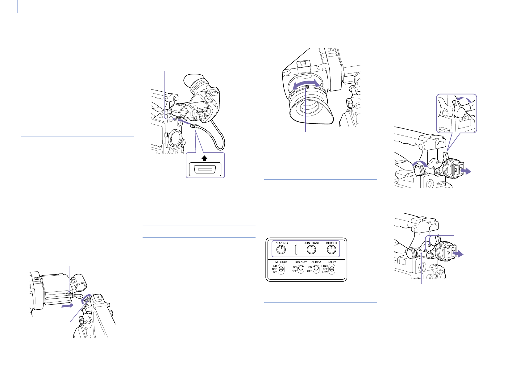
Attaching a Viewfinder
[Note]
When attaching a viewfinder, take note of the following
points.
Be sure to the power off the camcorder before coupling
the viewfinder connector to the camcorder’s VF
connector (26-pin). If you make this connection when the
camcorder power is on, the viewfinder may not function
properly.
Couple the viewfinder connector firmly to the
camcorder’s VF connector (26-pin). If the coupling is loose,
noise may appear on the video or the tally light may not
operate properly.
1 [1] Loosen the viewfinder left-to-right
positioning ring, [2] attach the viewfinder to
the viewfinder fitting shoe, and [3] tighten the
viewfinder left-to-right positioning ring.
Slide stopper
2 Couple the viewfinder connector to the VF
connector (26-pin).
VF connector (26-pin)
Up
You can detach the viewfinder by following the
attaching procedure in reverse order. But, when
detaching the viewfinder from the attachment
shoe, pull up the stopper.
Adjusting the Diopter
Turn the diopter adjustment ring until the
viewfinder image is sharpest.
Diopter adjustment ring
You can also attach a commercially available
protection filter, close-up lens, etc. that is 52 mm
in diameter.
Adjusting the Screen
Adjust the brightness, contrast, and peaking of the
viewfinder screen with the controls shown below.
Outlines: Adjust using the PEAKING knob.
Contrast: Adjust using the CONTRAST knob.
Brightness: Adjust using the BRIGHT knob.
the way so that your right leg does not hit the
viewfinder while you are carrying the camcorder.
1 Loosen the front-to-back viewfinder
positioning levers and the front-to-back
viewfinder positioning knobs, and then pull
the viewfinder slide assembly forward.
2 Using a 2.5 mm diameter hexagonal wrench,
detach the viewfinder slide assembly.
Hex socket bolts
[1]
[2]
Left-to-right positioning
ring
[3]
Attaching the BKW-401 Viewfinder
Rotation Bracket
By fitting an optional BKW-401 Viewfinder Rotation
Bracket, you can rotate the viewfinder out of
Viewfinder slide assembly
3 Attach the BKW-401 with the supplied bolts.
Page 22

2. Preparation: Attaching a Viewfinder
000
22
Bolts supplied with the BKW-401
4 Adjust the front-to-back position so that the
arm of the BKW-401 does not touch the
handle when it is raised.
Adjust position so that arm does not
touch handle
Page 23
2. Preparation
000
23
Using the Camcorder for the First Time
When using the camcorder for the first time,
configure the following settings in the menu.
For details about menu operations, see “Basic Setup Menu
Operations” (page 88).
Setting the Time Zone
Set the time zone for the region of use. The default
value is “UTC Greenwich.”
1 Select Operation >Time Zone >Time Zone in
the setup menu.
2 Select the time zone to use.
Setting the Date and Time of the
Internal Clock
Set the year, month, day, and day-of-week of the
internal clock.
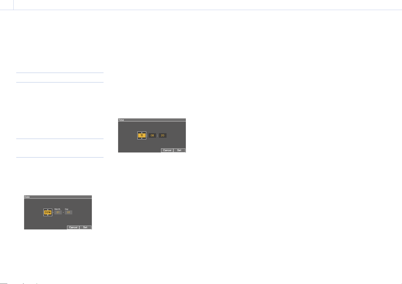
1 Select Maintenance >Clock Set >Date in the
setup menu.
The Date screen appears.
3 Turn the MENU knob to set the year, month, or
day, and then press the knob.
4 Repeat steps 2 and 3 to set the remaining
digits.
5 Press the SET button.
The internal clock is set to the date set in steps
2 to 4.
Next, set the time.
6 Select Maintenance >Clock Set >Time in the
setup menu.
The Time screen appears.
7 Set the time in the same way as when setting
the date.
8 Press the SET button.
The time is registered in the internal clock.
To cancel the setting, press the Cancel button.
2 Turn the MENU knob to select the year, month,
or day, and then press the knob.
The selected year, month, or day becomes
editable.
Page 24
2. Preparation
000
24
Mounting and Adjusting the Lens
[Note]
When connecting or disconnecting the lens cable to this
connector, power off the camcorder first.
Attaching a Lens
The lens is available separately.
This section describes an example lens
attachment.
For information about using the lens, refer to the operation
manual for the lens.
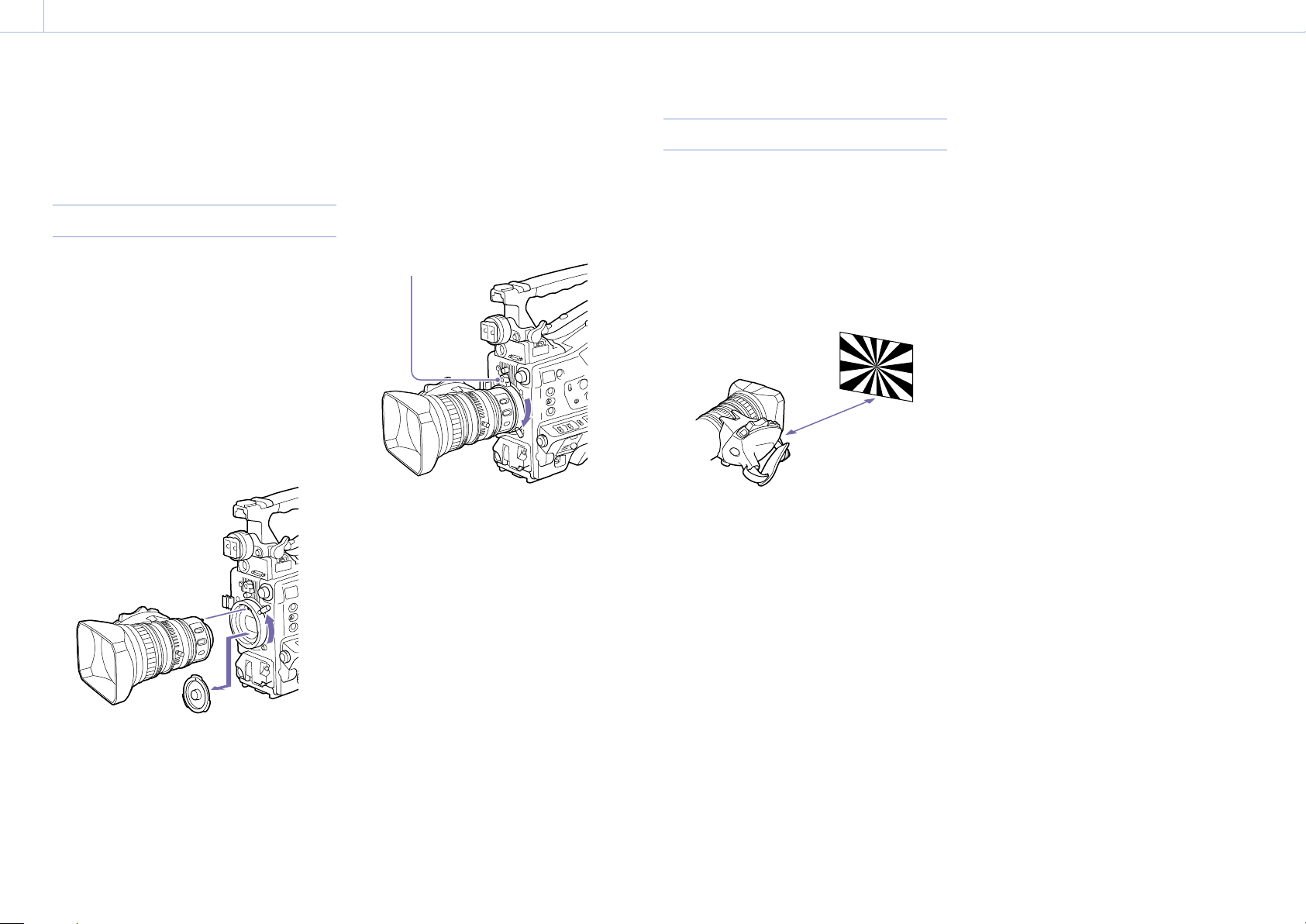
1 Push the lens locking lever up and remove the
lens mount cap from the lens mount.
2 Align the center pin on the lens with the
center slot in the lens mount, and insert the
lens into the mount.
2
1
1
3 Holding the lens in place, push the lens
locking lever down to lock the lens.
[CAUTION]
If the lens is not firmly locked, it may come off
while the camcorder is being used. This could
cause a serious accident. Make sure the lens is
firmly locked. It is recommended that the lens
mount securing rubber be put on the lens
locking lever as illustrated below.
Lens mount securing rubber
3
4 Connect the lens cable to the LENS connector.
5 Secure the lens cable with the cable clamp.
If an aberration correction lens is attached
The aberration correction function is activated
automatically.
aberration correction lens may require more time
than normal because of data loading at start-up.
Contact a Sony service representative for
information about aberration correction lenses.
1) The aberration correction function does not operate if
Maintenance >Camera Config >ALAC in the setup menu
is set to Off.
1)
Starting the camcorder with an
Adjusting the Flange Focal Length
If the lens does not stay in focus properly as you
zoom from telephoto to wide angle, adjust the
flange focal length (the distance from the plane
of the lens mounting flange to the imaging plane,
also called flange-back).
Make this adjustment just one time after mounting
or changing the lens.
When carrying out the adjustment, use a flange
focal length adjustment chart as the subject.
Approx. 3 m (10 ft.)
[Notes]
If you use a subject with insufficient contrast, or move the
camcorder or subject during adjustment, this will cause
an adjustment error.
Place the subject (the flange focal length adjustment
chart) so that it appears at the center of the screen at the
telephoto end. Arrange it so that no nearby object (no
object closer to the camera than the chart) enters the
screen at the wide-angle end.
1 Set the iris to manual.
2 Place the supplied flange focal length
adjustment chart about 3 m (10 ft) in front of
the camera.
3 Open the iris.
The depth-of-field is reduced when the iris is
open, making adjustment easier.
5 Use manual or power zoom to set the lens to
telephoto.
6 Point the camcorder at the chart by turning
the focus ring and focus on it.
7 Set the zoom ring to wide angle.
8 Turn the F.f or F.B ring until the chart is in
focus, being careful not to disturb the focus
ring.
9 Repeat steps 5 to 8 until the chart stays in
focus all the way from wide angle to
telephoto.
10 Tighten the F.f or F.B ring fixing screws.
4 Loosen the fixing screws on the F.f or F.B ring
(flange focal length adjustment ring).
Page 25
2. Preparation
000
25
Preparing the Audio Input System
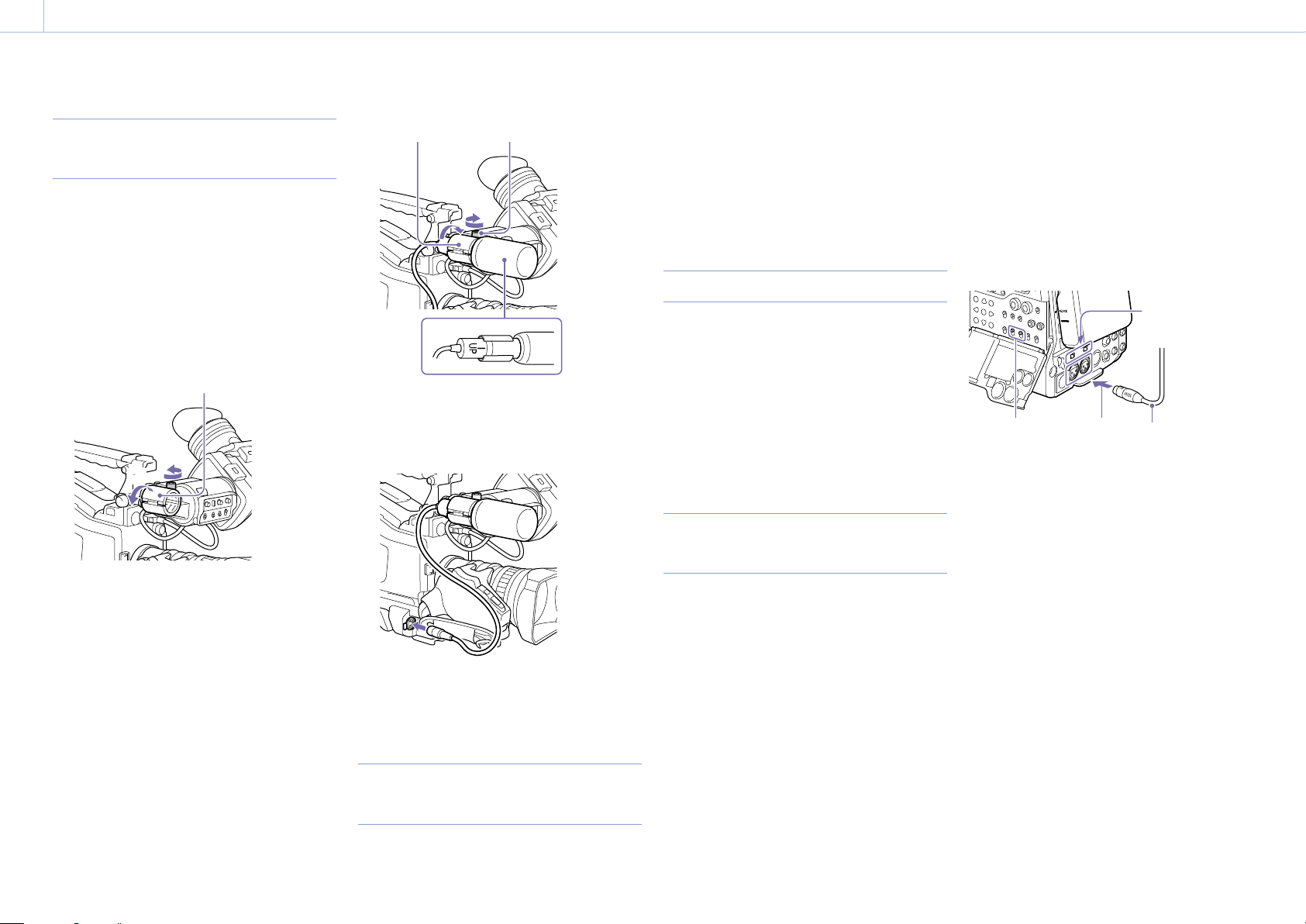
Connecting a Microphone to the MIC
IN Connector
You can attach a stereo microphone (available
separately) to the microphone holder of the
viewfinder (available separately).
This section describes an example microphone
attachment.
For procedures for attaching a microphone holder to other
viewfinders, refer to the manual supplied with each viewfinder.
1 Loosen the screw and open the microphone
holder clamp.
Microphone holder clamp
[1]
[2]
[2] [3]
[1]
3 Plug the microphone cable into the MIC IN
connector, then set the AUDIO IN switch for
the channel on which you want to record the
audio from this microphone to FRONT.
connectors, using an optional CAC-12 Microphone
Holder.
Supported microphones: ECM-674/678 electret
condenser microphone
For details about attaching the microphone holder and
microphone, refer to the instruction manual of each product.
Attaching a Wireless Receiver
To use a Sony wireless microphone system, power
the camcorder off and then attach a wireless
receiver.
DWR-S02D Digital Wireless Receiver
WRR-855S, URX-S03D UHF Synthesized Tuner
Unit
For details about attaching a wireless receiver, refer to the
instruction manual of each product.
Connecting Line Input Audio
Equipment
With the XLR connection automatic detection
function switched on: When a cable is
connected to the AUDIO IN CH-1 or CH-2
connector, the input from that connector is
automatically selected for audio recording,
regardless of the setting of the AUDIO IN CH1/
CH2 switch.
The XLR connection automatic detection function
can be switched on/off using Maintenance
>Audio >Rear XLR Auto in the setup menu.
[4]
[2][1]
[1] AUDIO IN CH1/CH2 switches
[2] To AUDIO IN CH-1 or CH-2 connector
[3] Monaural microphone
[4] AUDIO IN selector switches
[3]
2 Place the microphone in the microphone
holder.
[1] Place the microphone in the holder so that
“UP” is at the top.
[2] Close the microphone holder.
[3] Tighten the screw.
4 Secure the microphone cable with the cable
clamp.
Connecting Microphones to the
AUDIO IN Connectors
You can connect up to two monaural
microphones to the AUDIO IN CH-1/CH-2
1 Connect the audio output connector of the
audio equipment that supplies the line input
signal to the AUDIO IN CH-1 or CH-2
connector.
2 Set the AUDIO IN selector for the channel to
which the audio signal source is connected to
LINE.
XLR connection automatic detect function
With the XLR connection automatic detection
function switched off (the factory default
setting): Set the AUDIO IN CH1/CH2 switch
to REAR for the channels to which the audio
equipment is connected.
Page 26
2. Preparation
000
26
Attaching and Adjusting Peripheral Devices
[Note]
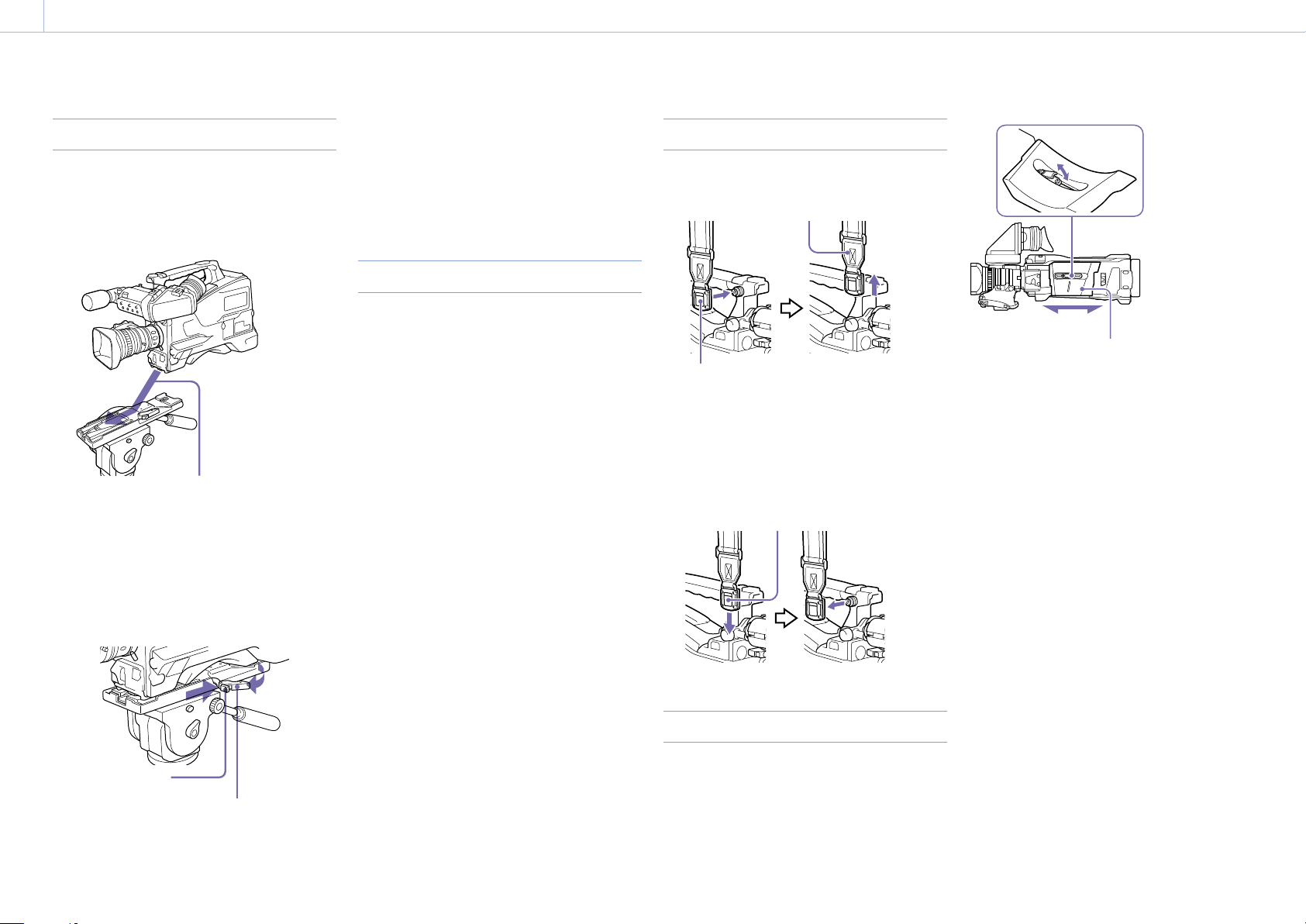
Mounting on a Tripod
1 Attach the optional VCT-14/U14 Tripod
Adaptor to the tripod.
2 Mount the camcorder on the tripod adaptor.
The tripod adaptor pin may remain in the engaged position
even after the camcorder is removed. If this happens, press
the red button and move the lever as shown above until
the pin returns to the stowed position. If the pin remains
in the engaged position, you will not be able to mount the
camcorder on the tripod adaptor.
Connecting a Video Light
Attaching the Shoulder Strap
1 Fit one of the clips to a shoulder strap fitting.
1,3
Pull up the strap to lock the fitting.
Slide the camcorder forward along the
groove in the adaptor until it clicks.
3 Make sure that the camcorder is securely
attached by moving it back and forth.
To remove the camcorder from the tripod
attachment, hold down the red button and pull
the lever in the direction of the arrow.
Red button
Lever
With this camcorder, you can use the Anton Bauer
Ultralight 2 or equivalent video light (powered by
12 V with maximum power consumption of 50 W).
If you connect the video light to the LIGHT
connector on the camcorder and set the LIGHT
switch to AUTO, you can turn the light on and
off automatically as you start and stop recording
on this camcorder.
The output of the LIGHT connector on the
camcorder is regulated to 12 V even when the
camcorder is supplied with over 12 V power
(through the DC IN connector or battery pack).
The brightness or color temperature of the light
will not change in response to voltage increase.
[Notes]
Do not connect video lights with power consumption of
50 W or greater.
The brightness or color temperature of the light will
change when the voltage (supplied through the DC IN
connector or from the battery pack) is less than 12 V.
To attach a video light, fit the video light to
the accessory shoe on the camcorder grip,
and connect the video light cable to the LIGHT
connector.
[Note]
The accessory shoe on the camcorder is of the 1/4-inch
tapped hole type. If you want to replace this with a slide-type
shoe, use the supplied cold shoe kit.
Clip
2 Fit the other clip to the shoulder strap fitting
on the other side of the grip in the same way.
To remove the shoulder strap, refer to the
following diagram.
Press here and pull in the direction shown by the
arrow to release.
Adjusting the Shoulder Pad Position
You can slide the shoulder pad back and forth
within a 40 mm range. This adjustment helps
you get the best balance for shooting with the
camcorder on your shoulder.
2
Shoulder pad
1 Raise the lever in the center of the shoulder
pad to unlock the shoulder pad.
2 Slide the shoulder pad backward or forward
until it is in the most convenient position.
3 Bring down the lever to lock the shoulder pad
in the selected position.
Page 27
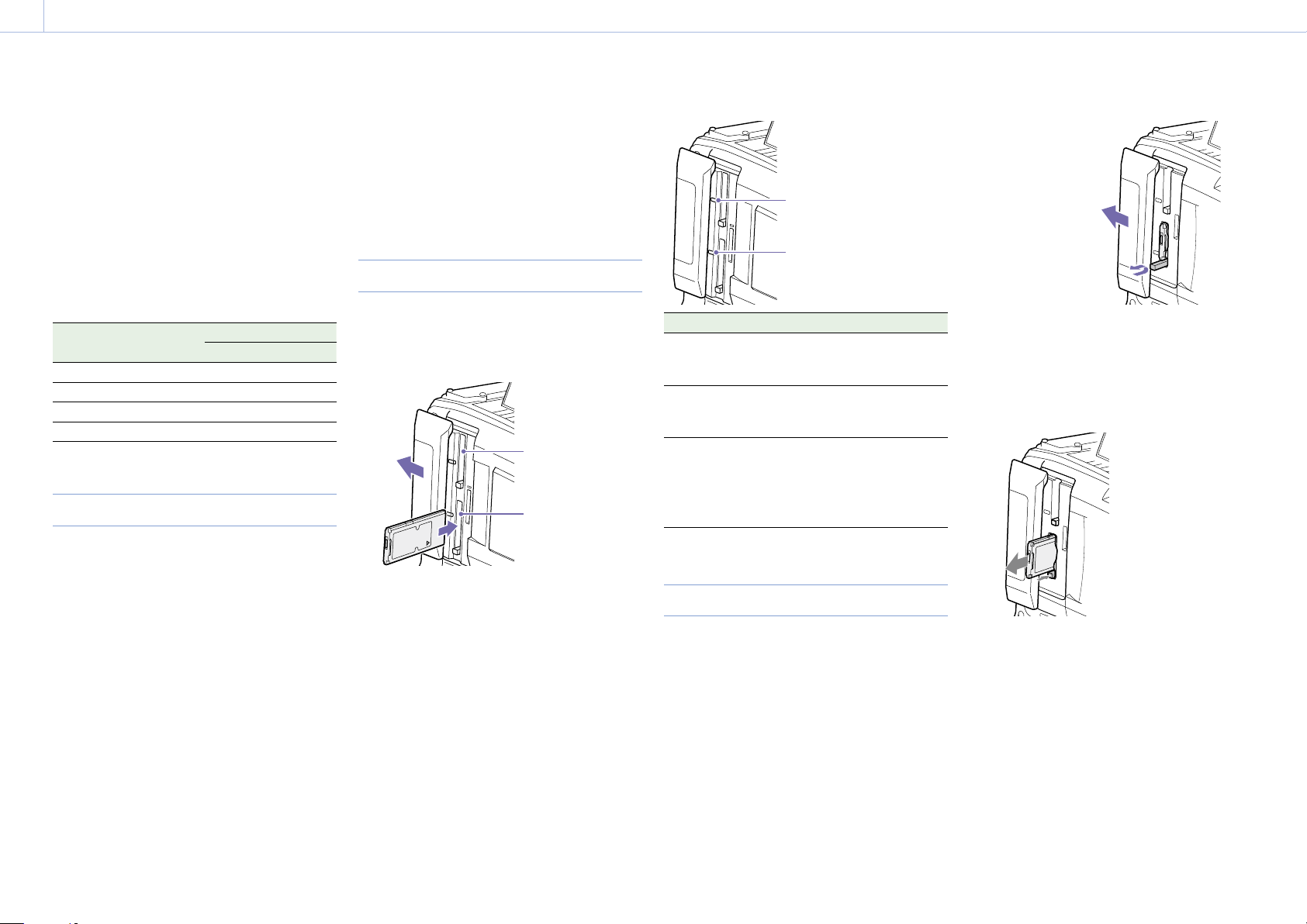
2. Preparation
000
27
Handling SxS Memory Cards
This camcorder records video and audio on SxS
memory cards (not supplied) loaded into one or
both of its memory card slots.
In addition to SxS memory cards, you can also
use XQD memory cards (not supplied) with the
QDA-EX1 XQD ExpressCard Adaptor (optional) or
SDXC/SDHC cards (not supplied) with the MEADSD02 Media Adaptor (optional) in the camcorder
to make recordings.
The file system supported by each type of media is
given below.
Memory card File system
exFAT UDF FAT
SxS memory cards Yes Yes No
XQD memory cards Yes Yes No
SDXC cards Yes No No
SDHC cards No No Yes
About SxS Memory Cards
trademarks and trade names are the property of
their respective owners.
[Note]
Use SxS PRO+ memory cards when recording in XAVC-I
3840×2160P.
Inserting SxS Memory Cards
1 Slide the cover to the left to open.
2 Insert an SxS memory card into a card slot.
Slot A
Slot B
Slot A access indicator
Slot B access indicator
Indicator Slot status
Lights in
orange
Lights in
green
Not lit No SxS memory card is loaded.
Accessing the SxS memory card
(lights during data reading and
writing)
Standby (the loaded SxS memory
card is ready for recording or
playback)
An unusable card is loaded.
An SxS memory card is loaded, but
the other slot is selected.
Press the button once
to release the lock.
2 Press the EJECT button again to eject the card.
[Note]
When you press the EJECT button, take care not to
impede the SxS memory card. If the movement of
the SxS memory card is impeded, the lock may fail to
release.
SxS memory cards
Use Sony SxS memory cards (SxS PRO+, SxS PRO,
or SxS-1) with this camcorder.
SxS PRO+ series
SxS PRO series
SxS-1 series
The memory cards listed above comply with the
ExpressCard memory card standard.
SxS, SxS PRO+, SxS PRO, and SxS-1 are
trademarks of Sony Corporation.
The ExpressCard label and logo are the
property of the Personal Computer Memory
Card International Association (PCMCIA) and
are licensed to Sony Corporation. All other
[Note]
Make sure to insert the SxS card in the correct
orientation. Hold the card with the arrow on one side
facing the direction shown in the diagram, and then
insert the card.
The ACCESS indicator lights in orange, and
then lights in green to indicate that the
memory card is usable.
3 Close the cover.
ACCESS indicator status
Card slots A and B each have an ACCESS indicator
that indicate the slot status.
Ejecting SxS Memory Cards
1 Open the cover, and then press the EJECT
button to release the lock and extract the
button.
[Note]
Data integrity cannot be guaranteed if you power the
camcorder off or remove a memory card while the card
is being accessed. All data recorded on the card may be
discarded. Always make sure that the ACCESS indicator is
lit green or not lit before you power the camcorder off or
remove a memory card.
Page 28

2. Preparation: Handling SxS Memory Cards
000
28
Selecting the SxS Memory Card to
Use
When SxS memory cards are loaded in both slot A
and slot B, you can press the SLOT SELECT button
to select the SxS memory card to use.
When the remaining recording time on the
recording SxS memory card falls below 60
seconds, the remaining capacity indicator for
the corresponding media slot flashes on the
viewfinder screen to indicate that the camcorder
will switch SxS memory cards soon.
Subsequently, the camcorder switches
automatically to the other card when the selected
card becomes full, and recording continues.
[Notes]
The SLOT SELECT button is disabled during playback. The
memory cards are not switched even if you press the
button. Button operations are enabled when a thumbnail
screen (page 79) is displayed.
In 1-slot Simul Rec mode, recording may not be able to
continue after switching cards if the next card already has
200 or more clips.
Formatting (Initializing) SxS Memory
Cards
When an unformatted SxS memory card or an SxS
memory card formatted in another specification is
inserted, a message notifying you that the media
has a different file system appears. In this case,
format the memory card in the following way.
SxS memory cards are formatted in exFAT or FAT
by factory default.
[Note]
SxS memory cards must be formatted on an XDCAM device
that supports the exFAT or UDF file system or on this
camcorder. Cards in other formats cannot be used.
1 Select Operation >Format Media in the setup
menu.
2 Select Media(A) (slot A) or Media(B) (slot B).
3 Turn the MENU knob to select [Execute], then
press the knob.
A confirmation screen prompting whether to
format the card appears.
4 Turn the MENU knob to select [Execute] on the
confirmation message screen, then press the
knob.
Formatting begins.
During formatting, a message is displayed, and
the ACCESS indicator is lit orange.
When formatting ends, a completion message
appears. Press the MENU knob to dismiss the
message.
If formatting fails
A format operation may fail because the SxS
memory card is write protected, or because it is
not the type of card specified for use with this
camcorder.
In this case, an error message appears. Follow the
instructions in the error message and exchange
the card for an SxS memory card that can be used
with this camcorder.
[Notes]
Formatting a memory card erases all data, including
recorded video data and setup files.
Use the format function of this camcorder to format SxS
memory cards for use on this camcorder. The formats of
cards formatted on other devices are not recognized as
valid formats, making it necessary to format them again
on this camcorder.
Formatting while recording
Even while recording, the SxS memory card loaded
in the other card slot can be formatted.
[Notes]
Formatting is not supported during 1-slot Simul Rec,
during playback, or when the thumbnail screen is
displayed.
During formatting, recording to an SxS memory card
loaded in the other card slot cannot be started.
Checking the Remaining Recording
Time
You can check the remaining capacity of the SxS
memory cards loaded in the two slots by checking
the recording media remaining capacity indicator
in the viewfinder.
The remaining recording time is calculated from
the remaining capacity of the media in each slot
and the current video format (recording bit rate),
and is displayed in units of minutes.
You can check the remaining capacity on a bar
graph by displaying the Media Status screen
(page 15).
[Note]
A mark appears when a memory card is write protected.
When to exchange SxS memory cards
The warning message “Media Near Full” appears,
the WARNING indicator and the REC indication
on the viewfinder screen flash, and the buzzer
sounds when the total remaining recording
time of the two memory cards falls to five
minutes during recording.
Exchange one of the cards for media with
available recording capacity.
If you continue recording, the message “Media
Full” appears and recording stops when the
total remaining recording time falls to 0.
[Note]
About up to 600 clips can be recorded on one SxS memory
card.
The display of remaining recording time changes to “0”
and the message “Media Full” appears when the clip limit is
reached.
Restoring SxS Memory Cards
If for any reason an error should occur in a memory
card, the card must be restored before use.
When you load an SxS memory card that needs to
be restored, a message appears in the viewfinder
to ask whether you want to restore it.
To execute the restore, turn the MENU knob to
select [Execute], and then press the knob.
The restoration starts.
During restoration, a message is displayed, and the
ACCESS indicator is lit orange.
When restoration ends, a completion message
appears. Press the MENU knob to dismiss the
message.
If restoration fails
Write protected SxS memory cards and cards on
which memory errors have occurred cannot be
restored. A warning message appears for such
cards. Follow the instructions in the message
and unprotect the card or replace it with
another card.
SxS memory cards on which memory errors
have occurred may become usable if they are
reformatted.
In some cases, some clips can be restored while
others cannot. The restored clips can be played
normally.
If the message “Could not Restore Some Clips”
keeps appearing after repeated attempts at
restoration, it may be possible to restore the SxS
memory card with the following procedure.
[1] Use the application software (page 162)
to copy the required clips to another SxS
memory card.
[2] Format the unusable SxS memory card on
the camcorder.
[3] Copy the required clips back to the newly
formatted SxS memory card.
Page 29

2. Preparation
000
29
Handling SD Cards for Saving Configuration Data
The following SD cards can be used for saving
configuration data.
SDHC memory cards
UHS, Capacity: 4 to 32 GB)
* Referred to as “SD cards” in this manual.
*
(Speed Class: 4 to 10, non-
Formatting (Initializing) SD Cards
SD cards must be formatted the first time they are
used in the camcorder.
SD cards for use in the camcorder should be
formatted using the format function of the
camcorder. If a message appears when the SD card
is inserted into the camcorder, format the SD card.
1 Select Operation >Format Media >SD Card
(Utility) in the setup menu.
A confirmation screen prompting whether to
format the card appears.
2 Turn the MENU knob to select [Execute], then
press the knob.
Formatting begins.
During formatting, a message is displayed, and
the ACCESS indicator is lit orange.
When formatting ends, a completion message
appears. Press the MENU knob to dismiss the
message.
[Note]
Formatting an SD card erases all data on the card. The card
cannot be restored.
Checking the Remaining Capacity
You can check the remaining capacity on an SD
card on the Media Status screen (page 15).
To use an SD card formatted on the camcorder in
the slot of another device, make a backup of the
card, then reformat the card in the device to be
used.
Page 30

2. Preparation
000
30
Using a Media Adaptor
[Notes]
For professional applications, the use of other media will
not provide the same high reliability and durability that is
obtained using SxS memory cards.
Not all memory cards are guaranteed to work with this
camcorder. For compatible memory cards, contact your
Sony dealer.
XQD Memory Cards
By using an optional QDA-EX1 XQD ExpressCard
Adaptor, you can insert an XQD memory card into
an SxS memory card slot and use it instead of an
SxS memory card for recording and playback.
For details about using a QDA-EX1 XQD ExpressCard Adaptor,
refer to the instruction manual supplied with the adaptor.
[Notes]
High-speed playback may not be properly achieved with
an XQD memory card.
High frame rate recording in XAVC-I 3840×2160P and
XAVC-L 3840×2160P may fail, depending on the media
used, if an unsupported media error message appears.
Slow motion recording using the Slow & Quick Motion
recording function cannot be used with an XQD memory
card.
Formatting (initializing)
XQD memory cards must be formatted the first
time they are used in the camcorder.
XQD memory cards for use in the camcorder
should be formatted using the format function
of the camcorder. If a message appears when the
XQD memory card is inserted into the camcorder,
format the XQD memory card.
If an unformatted XQD memory card or an XQD
memory card that was formatted in a different
specification is inserted, a message asking for
confirmation to format media or a message
notifying you that the media has a different file
system appears.
1 Select Operation >Format Media in the setup
menu.
2 Select Media(A) (slot A) or Media(B) (slot B).
3 Turn the MENU knob to select [Execute], then
press the knob.
A confirmation screen prompting whether to
format the card appears.
4 Turn the MENU knob to select [Execute] on the
confirmation message screen, then press the
knob.
Formatting begins.
During formatting, a message is displayed, and
the ACCESS indicator is lit orange.
When formatting ends, a completion message
appears. Press the MENU knob to dismiss the
message.
[Note]
Formatting an XQD memory card erases all data on the card,
including protected video. The data cannot be restored.
Connection between the camcorder and a
computer
Insert the recorded XQD memory card into a slot
in the camcorder, and connect the camcorder to a
computer using a USB cable.
To use a memory card formatted on the
camcorder in the slot of another device
First, make a backup of the card, then reformat the
card in the device to be used.
SD Cards
By using an optional MEAD-SD02 Media Adaptor,
you can insert an SD card into an SxS memory card
slot and use it for recording and playback.
[Note]
If an SD card and another memory card are used at the same
time, the camcorder does not switch cards when the media
becomes full. Instead, recording stops.
The following SD cards are supported.
SDXC memory cards (SD speed class: Class 10)
SDHC memory cards (SD speed class: Class 10)
1) Supported if the file system is exFAT.
2) Supported if the file system is FAT.
For details about using an MEAD-SD02 Media Adaptor, refer to
the instruction manual supplied with the adaptor.
[Notes]
High-speed playback may not be properly achieved with
an SD card.
Recording and playback using SD cards is not supported
when shooting in XAVC-I or XAVC-L 3840×2160P format.
Slow motion recording using the Slow & Quick Motion
recording function cannot be used with an SDXC card.
1)
2)
Formatting (initializing)
SD cards must be formatted the first time they are
used in the camcorder.
SD cards for use in the camcorder should be
formatted using the format function of the
camcorder. If a message appears when the SD card
is inserted into the camcorder, format the SD card.
If an unformatted SD card or an SD card that was
formatted in a different specification is inserted, a
message asking for confirmation to format media
or a message notifying you that the media has a
different file system appears.
Format the card using the following procedure.
1 Select Operation >Format Media in the setup
menu.
2 Select Media(A) (slot A) or Media(B) (slot B).
3 Turn the MENU knob to select [Execute], then
press the knob.
A confirmation screen prompting whether to
format the card appears.
4 Turn the MENU knob to select [Execute] on the
confirmation message screen, then press the
knob.
Formatting begins.
During formatting, a message is displayed, and
the ACCESS indicator is lit orange.
When formatting ends, a completion message
appears. Press the MENU knob to dismiss the
message.
[Note]
Formatting an SD card erases all data on the card, including
protected video. The data cannot be restored.
Connection between the camcorder and a
computer
Insert the recorded SD card into a slot in the
camcorder, and connect the camcorder to a
computer using a USB cable.
To use a memory card formatted on the
camcorder in the slot of another device
First, make a backup of the card, then reformat the
card in the device to be used.
Page 31

3. Settings and Adjustments
3. Settings and Adjustments
000
31
Format Settings
You can set the file system, system frequency, and video format using Operation >Format in the setup
menu.
For details about menu operations, see “Basic Setup Menu Operations” (page 88).
Selecting the File System
You can select the file system.
1 Select Operation >Format >File System in the setup menu.
2 Turn the MENU knob to select a file system, then press the knob.
A confirmation screen appears.
3 Select [Execute] to execute, or select [Cancel] to cancel, and then press the MENU knob.
The camcorder will reboot automatically after executing [Execute].
[Note]
The file system cannot be changed during recording/playback or while the thumbnail screen is displayed.
Switching the System Frequency
Switching the Video Format
Refer to “Video Formats” (page 32) as required when switching the video format.
1 Select Operation >Format >Rec Format in the setup menu.
2 Turn the MENU knob to change the video format, and press the knob.
A confirmation screen appears.
3 Select [Execute] to execute, or select [Cancel] to cancel, and then press the MENU knob.
You can switch the system frequency as required.
[Notes]
The system frequency cannot be changed during recording/playback or while the thumbnail screen is displayed.
After switching between 29.97 and 59.94 or between 25 and 50, the camcorder does not reboot automatically.
1 Select Operation >Format >Frequency in the setup menu.
2 Turn the MENU knob to select the system frequency, and press the knob.
A confirmation screen appears.
3 Select [Execute] to execute, or select [Cancel] to cancel, and then press the MENU knob.
The camcorder will reboot automatically after executing [Execute].
Page 32

3. Settings and Adjustments: Format Settings
000
32
Video Formats
The following recording formats can be selected for different combinations of video resolution and
system frequency.
System frequency
(Operation >Format
>Frequency in setup
menu)
59.94/50 Yes – – XAVC-I 3840×2160P 3840×2160
29.97/25/23.98 Yes – – XAVC-I 3840×2160P 3840×2160
File system
(Operation >Format
>File System in setup
menu)
exFAT UDF FAT
Yes – – XAVC-I 1920×1080P 1920×1080
Yes – – XAVC-I 1920×1080i
Yes – XAVC-I 1280×720P 1280×720
Yes – – XAVC-L 3840×2160P 3840×2160
Yes – – XAVC-L 50 1920×1080P 1920×1080
Yes – – XAVC-L 50 1920×1080i
Yes – – XAVC-L 50 1280×720P 1280×720
Yes – – XAVC-L 35 1080P 1920×1080
Yes – – XAVC-L 35 1080i
Yes – – XAVC-L 25 1080i
Yes Yes – HD422 50 1080i 1920×1080
Yes Yes – HD422 50 720P 1280×720
Yes Yes Yes HQ 1920×1080i 1920×1080
Yes Yes Yes HQ 1440×1080i 1440×1080
Yes Yes Yes HQ 1280×720P 1280×720
– – Yes SP 1440×1080i 1440×1080
Yes Yes – MPEG IMX 50 720×486/720×576
Yes Yes – DVCAM 720×480/720×576
Yes – – XAVC-I 1920×1080P 1920×1080
Yes – – XAVC-L 3840×2160P 3840×2160
Yes – – XAVC-L 50 1920×1080P 1920×1080
Yes – – XAVC-L 35 1080P
Yes Yes – HD422 50 1080P 1920×1080
Yes Yes – HD422 50 720P 1280×720
Yes Yes Yes HQ 1920×1080P 1920×1080
Video format
(Operation >Format
>RecFormat in setup menu)
Picture size
Page 33

3. Settings and Adjustments: Format Settings
000
33
SDI OUT Connector, HDMI Output Connector, and VIDEO OUT Connector Output Formats
The signals that can be output from the SDI OUT connector, HDMI output connector, and VIDEO OUT connector are shown in the following table according to the Operation >Format setting in the setup menu.
One line is available when the signal output from the SDI OUT1 to 4 connectors is Quad Link output, up to two lines when the signal output is Dual Link output, and up to four lines when the signal output is Single
output.
Default values are shown underlined and in bold text.
[Notes]
The following restrictions apply when using XAVC proxy recording, when using network functions, or when XAVC Proxy Rec Start is assigned to an assignable switch.
3840×2160P SDI output format setting cannot be selected when recording at 3840×2160P.
720×486 or 720×576i SDI output format setting cannot be selected when recording at 1440×1080i.
If proxy recording or network functions are enabled during operation with 3840×2160P SDI output format setting, the SDI output setting changes to 1920×1080P (Level B).
Operation >Format (codec
omitted) in the setup menu
Proxy recording or
network function
OFF ON Proxy recording or network function
59.94 3840×2160P Selectable Not
selectable
Selectable Not
selectable
Selectable Not
selectable
Selectable Selectable 1920×1080P (Level A) 1920×1080P HD-Y HD-Y Single output
Selectable Selectable
Selectable Selectable 1920×1080i 1920×1080i HD-Y HD-Y Single output
Selectable Selectable 720×486i 720×480i Composite Composite
1920×1080P Selectable Selectable 1920×1080P (Level A) 1920×1080P HD-Y HD-Y Single output
Selectable Selectable
Selectable Selectable 1920×1080i 1920×1080i HD-Y HD-Y Single output
Selectable Selectable 720×486i 720×480i Composite Composite
1920×1080i Selectable Selectable
Selectable Selectable 720×486i 720×480i Composite Composite
1440×1080i Selectable Selectable
Selectable Not
selectable
1280×720P Selectable Selectable
Selectable Selectable 720×486i 720×480i Composite Composite
720×480i Selectable Selectable
Selectable Selectable – 720×480P Composite HD-Y No signal
Operation >Input/Output >Output Format in the setup menu
SDI Out 1/3 Output
HDMI Output VIDEO OUT SDI OUT 1 to 4 connector description
or
SDI Out 2/4 Output
3840×2160P Square
a)
– HD Sync – Quad Link output: 3840×2160 59.94P Level-B (3G Square) output using
OFF ON
all SDI OUT 1,2,3,4 connectors
3840×2160P 2SI
b)
– HD Sync – Dual Link output: 3840×2160 29.97P Level-B (3G 2SI) output using SDI
OUT 1,2 connectors or SDI OUT 3,4 connectors
3840×2160P
1920×1080P (Level B) – HD-Y HD-Y Single output
f)
Single output
1920×1080P (Level B) – HD-Y HD-Y Single output
e)
Single output
1920×1080i 1920×1080i HD-Y HD-Y Single output
e)
Single output
1920×1080i 1920×1080i HD-Y HD-Y Single output
720×486i 720×480i Composite – Single output
1280×720P 1280×720P HD Sync
c)
720×486i 720×480i Composite Composite
HD Sync
c)
e)
e)
Single output
Single output
Single output
a)
Page 34

3. Settings and Adjustments: Format Settings
000
34
Operation >Format (codec
omitted) in the setup menu
Proxy recording or
network function
OFF ON Proxy recording or network function
29.97 3840×2160P Selectable Not
selectable
Selectable Not
selectable
Selectable Selectable
Selectable Selectable 720×486i 720×480i Composite Composite
1920×1080P Selectable Selectable
Selectable Selectable 720×486i 720×480i Composite Composite
1280×720P Selectable Selectable
Selectable Selectable 720×486i 720×480i Composite Composite
23.98 3840×2160P Selectable Not
selectable
Selectable Not
selectable
Selectable Selectable
Selectable Selectable 1920×1080i (2-3PD) 1920×1080i (2-3PD) HD-Y HD-Y Single output
Selectable Selectable 720×486i (2-3PD) 720×486i (2-3PD) Composite Composite
1920×1080P Selectable Selectable
Selectable Selectable 1920×1080i (2-3PD) 1920×1080i (2-3PD) HD-Y HD-Y Single output
Selectable Selectable 720×486i (2-3PD) 720×486i (2-3PD) Composite Composite Single output
1280×720P Selectable Selectable
Selectable Selectable 720×486i (2-3PD) 720×486i (2-3PD) Composite Composite
Operation >Input/Output >Output Format in the setup menu
SDI Out 1/3 Output
HDMI Output VIDEO OUT SDI OUT 1 to 4 connector description
or
SDI Out 2/4 Output
3840×2160P 2SI
b)
– HD Sync – Dual Link output: 3840×2160 29.97P Level-B (3G 2SI) output using SDI
OFF ON
OUT 1,2 connectors or SDI OUT 3,4 connectors
3840×2160P
1920×1080PsF 1920×1080i HD-Y HD-Y Single output
f)
Single output
1920×1080PsF 1920×1080i HD-Y HD-Y Single output
1280×720P 1280×720P HD-Y
3840×2160P 2SI
b)
– HD Sync – Dual Link output: 3840×2160 23.98P Level-B (3G 2SI) output using SDI
e)
d)
HD-Y
d)
e)
Single output
Single output
Single output
OUT 1,2 connectors or SDI OUT 3,4 connectors
3840×2160P
1920×1080PsF – HD-Y HD-Y Single output
f)
Single output
1920×1080PsF – HD-Y HD-Y Single output
1280×720P (2-3PD) 1280×720P (2-3PD) HD-Y
d)
HD-Y
d)
e)
Single output
Single output
Page 35

3. Settings and Adjustments: Format Settings
000
35
Operation >Format (codec
omitted) in the setup menu
Proxy recording or
network function
OFF ON Proxy recording or network function
50 3840×2160P Selectable Not
selectable
Selectable Not
selectable
Selectable Not
selectable
Selectable Selectable 1920×1080P (Level A) 1920×1080P HD-Y HD-Y Single output
Selectable Selectable
Selectable Selectable 1920×1080i 1920×1080i HD-Y HD-Y Single output
Selectable Selectable 720×576i 720×576i Composite Composite
1920×1080P Selectable Selectable 1920×1080P (Level A) 1920×1080P HD-Y HD-Y Single output
Selectable Selectable
Selectable Selectable 1920×1080i 1920×1080i HD-Y HD-Y Single output
Selectable Selectable 720×576i 720×576i Composite Composite
1920×1080i Selectable Selectable
Selectable Selectable 720×576i 720×576i Composite Composite
1440×1080i Selectable Selectable
Selectable Not
selectable
1280×720P Selectable Selectable
Selectable Selectable 720×576i 720×576i Composite Composite
720×576i Selectable Selectable 720×576i 720×576i Composite Composite
Selectable Selectable – 720×576P Composite HD-Y No signal
25 3840×2160P Selectable Not
selectable
Selectable Not
selectable
Selectable Selectable
Selectable Selectable 720×576i 720×576i Composite Composite
1920×1080P Selectable Selectable
Selectable Selectable 720×576i 720×576i Composite Composite
1280×720P Selectable Selectable
Selectable Selectable 720×576i 720×576i Composite Composite
Operation >Input/Output >Output Format in the setup menu
SDI Out 1/3 Output
HDMI Output VIDEO OUT SDI OUT 1 to 4 connector description
or
SDI Out 2/4 Output
3840×2160P Square
a)
– HD Sync – Quad Link output: 3840×2160 50P Level-B (3G Square) output using all
OFF ON
SDI OUT 1,2,3,4 connectors
3840×2160P 2SI
b)
– HD Sync – Dual Link output: 3840×2160 25P Level-B (3G 2SI) output using SDI
OUT 1,2 connectors or SDI OUT 3,4 connectors
3840×2160P
1920×1080P (Level B) – HD-Y HD-Y Single output
f)
Single output
1920×1080P (Level B) – HD-Y HD-Y Single output
e)
Single output
1920×1080i 1920×1080i HD-Y HD-Y Single output
e)
Single output
1920×1080i 1920×1080i HD-Y HD-Y Single output
720×576i 720×576i Composite – Single output
1280×720P 1280×720P HD Sync
3840×2160P 2SI
b)
– HD Sync – Dual Link output: 3840×2160 25P Level-B (3G 2SI) output using SDI
c)
HD Sync
c)
e)
e)
Single output
Single output
Single output
OUT 1,2 connectors or SDI OUT 3,4 connectors
3840×2160P
1920×1080PsF 1920×1080i HD-Y HD-Y Single output
f)
Single output
1920×1080PsF 1920×1080i HD-Y HD-Y Single output
1280×720P 1280×720P HD-Y
e)
d)
HD-Y
d)
e)
Single output
Single output
Single output
a)
a) Enabled when CBKZ-Z450QL (QUAD-LINK 3G-SDI Upgrade License) is installed.
b) 2SI is displayed when CBKZ-Z450QL (QUAD-LINK 3G-SDI Upgrade License) is installed.
Page 36

3. Settings and Adjustments: Format Settings
000
36
c) 1080i sync signal output.
d) 1080PsF signal output.
e) Character information (superimposed) turns on/off in sync with the SDI Out2/4/HDMI Super character information display switching.
f) Character information (superimposed) turns on/off in sync with the 4K(QFHD) SDI OUT Super character information display switching.
Page 37

3. Settings and Adjustments
000
37
Expansion of Imaging Dynamic Range
You can set the imaging dynamic range to High Dynamic Range (HDR) mode to record and output
images with BT.20202 equivalent color space and increased dynamic range when the recording format is
4K QFHD or HD.
When this function is used together with the 1-slot Simul Rec function, a 4K QFHD main clip can be
recorded in high dynamic range and an MPEG HD422 subclip can be recorded in standard dynamic range
(SDR).
The High Dynamic Range function is available if the file system is exFAT.
[Notes]
Not supported for MPEG IMX and DVCAM file formats.
An SD format signal cannot be output when HDR is configured. If the signal format is SD and then HDR is selected, the
image is output in the default HD format.
Change the dynamic range mode setting with the Picture Cache Rec function set to Off.
Operation >Rec Function >Picture Cache Rec >Off
Setting the Dynamic Range
1 Select Operation >Base Setting >Shooting Mode in the setup menu.
2 Turn the MENU knob to select the dynamic range mode.
Select HDR to set to High Dynamic Range or SDR to set to standard dynamic range.
HDR settings
When HDR is selected for the dynamic range mode, configure HDR settings using Operation >HDR
Setting in the setup menu. For details, see page 93.
[Note]
This function is applied to the image in the viewfinder and LCD monitor. It is not applied to the recorded image or output
image.
HLG type when using HDR(HLG)
You can set the HLG type when the high dynamic range mode is set to HDR(HLG). For details, see
page 101.
HLG display assist function setting
When using the High Dynamic Range function, the contrast of the image displayed in the viewfinder and
LCD monitor may appear lower than when using standard dynamic range. In this case, you can adjust the
contrast of the image displayed in the viewfinder and LCD monitor to an appropriate level using the HLG
display assist function.
The HLG display assist function is automatically applied when HDR Setting >HD Rec/Out is set to
HDR(HLG).
You can also assign the HLG display assist function to an assignable switch, and then turn the function
on/off with a single button touch as required.
Page 38

3. Settings and Adjustments
000
38
Adjusting the Black Balance and White Balance
To ensure excellent image quality when using this
camcorder, conditions may require that both the
black balance and the white balance be adjusted.
Black balance and white balance adjustment
values that are automatically set by the camcorder
and the various settings are stored in the
camcorder memory and retained even when the
power is turned off.
Adjusting the Black Balance
The black balance will require adjustment in the
following cases.
When the camcorder is used for the first time
When the camcorder has not been used for a
long time
When the camcorder is used under conditions
in which the surrounding temperature has
changed greatly
When the GAIN selector (L/M/H/Turbo) values
have been changed with Operation >Gain
Switch in the setup menu.
It is not usually necessary to adjust the black
balance when using the camcorder after it has
been off.
In automatic black balance mode, adjustments are
performed in the following order: black set and
black balance. Manual black balance adjustment
can be selected from the setup menu.
Automatic black balance adjustment is disabled in
the following cases.
During recording
During special recording modes
When the shutter mode is SLS
1 Set the OUTPUT/DCC switch to CAM.
The message “Executing…” appears during
execution, and changes to “OK” when the
adjustment finishes.
Adjustment values are saved to memory
automatically.
[Notes]
During the black balance adjustment, the iris is
automatically closed.
During the black balance adjustment, the gain selection
circuit is automatically activated so you may see flickering
on the viewfinder screen, but this is not a fault.
If automatic black balance adjustment cannot be
made
If the black balance adjustment cannot be
completed normally, an error message will appear
for about three seconds on the viewfinder screen.
Error message
NG: Iris not Closed The lens iris did not close;
NG: Timeout Adjustment could not be
If any of the above error messages is displayed,
retry the black balance adjustment.
If the error message occurs again, an internal
check is necessary.
For information about this internal check, refer to the
Maintenance Manual.
[Note]
If the lens cable is not firmly connected to the LENS
connector, it may not be possible to adjust the lens iris. If this
happens, the black balance will be incorrect.
Meaning
adjustment was impossible.
completed within the
standard number of
attempts.
Adjusting the White Balance
1 Set the switches and selectors as shown
below.
GAIN switch: L (set to a gain value that is as
small as possible)
OUTPUT/DCC switch: CAM
WHITE BAL switch: A or B
1) Adjustment values are saved to memory B only when
Operation >White Setting >White Switch<B> in the
setup menu is set to Memory.
1)
2 Set the FILTER knob to suit the lighting
conditions as follows.
3 Place a white test card under the same lighting
conditions as the subject to be shot and zoom
in on it.
Alternatively, any white object such as a cloth
or a wall can be used.
The absolute minimum white area is as
follows.
Rectangle centered on the screen
The lengths of the sides are 70% of the length
and width of the screen. 10% or more of the
surface area of the image within the rectangular
area must be white.
[Note]
Make sure there are no bright spots in the rectangle.
4 Adjust the lens iris.
Iris adjusted manually: Set the iris to an
appropriate setting.
Iris adjusted using auto iris: Set the automatic/
manual switch on the lens to automatic.
The message “Executing…” appears during
execution, and changes to “OK: (color
temperature of subject)” when the adjustment
finishes.
The adjustment values are saved automatically
in the memory selected in step
[Note]
The iris may hunt1) during the adjustment. To prevent
this, adjust the iris gain knob (indicated as IG, IS, or S) on
the lens.
1) Hunting: Repeated brightening and darkening of
the image, resulting from repeated response to
automatic iris control.
For details, refer to the lens operation manual.
1 (A or B).
If the automatic white balance adjustment cannot
be made
If the white balance adjustment cannot be
completed normally, an error message will appear
for about three seconds on the viewfinder screen.
Error message Meaning
NG: Low Light The white video level is too
low. Either open the lens iris or
increase the gain.
NG: High Light The white video level is too
high. Either stop down the lens
iris or change the ND filter.
NG: Color Temp.
High
NG: Color Temp.
Low
The color temperature of the
subject lighting is too high,
and could not be adjusted.
Adjust the color temperature
of the lighting, then update
memory.
The color temperature of the
subject lighting is too low, and
could not be adjusted. Adjust
the color temperature of the
lighting, then update memory.
2 Push the AUTO W/B BAL switch to BLACK and
release the switch.
Always readjust the white balance when the
lighting conditions change.
5 Push the AUTO W/B BAL switch to WHITE and
then release the switch.
Page 39

3. Settings and Adjustments: Adjusting the Black Balance and White Balance
000
39
Error message Meaning
NG: Out of Range Value could not be adjusted
because the difference
between the current value and
reference value exceeds the
adjustment range.
NG: Poor White
Area
NG: Timeout Adjustment could not be
If any of the above error messages is displayed,
retry the white balance adjustment. If the error
message occurs again, an internal check is
necessary.
For information about this internal check, refer to the
Maintenance Manual.
The white surface of the
subject is too narrow, and
could not be adjusted.
completed within the specified
time.
If you have no time to adjust the white balance
Set the WHITE BAL switch to PRST.
Changing the color temperature when the ND
filter is switched
4 Repeat steps 2 and 3 as required.
Switching electrical CC filters with an assignable
switch
You can assign the function that switches between
electrical CC filters to an assignable switch. This
allows you to switch between color temperatures
(3200K/4300K/5600K/6300K) that have been
assigned using up to four positions (A to D) with
each press of the assignable switch.
1 Select Maintenance >White Filter in the setup
menu.
2 Select the position to which to assign a CC
filter by selecting one of [Electrical CC<A>] to
[Electrical CC <D>], and then turn the MENU
knob to select the desired color temperature.
Select “-----” with Electrical CC<C> or <D>
selected.
When the assignable switch is pressed, the
setting for that position is not displayed. For
example, if “-----” is set for one position, then
switching between the remaining three
positions is carried out.
allowing you to save a total of eight adjustment
values (4×2). However, the contents of the
memories are not linked to ND filter settings in the
following case.
When the number of memories allocated to
each of A and B is limited to one by setting
Operation >White Setting >Filter White Memory
in the setup menu to Off.
Also, when Operation >White Setting >White
Switch<B> in the setup menu is set to [ATW
(Auto Tracing White Balance)], and the WHITE BAL
switch is set to B, the ATW function is activated
to automatically adjust the white balance of the
picture being shot for varying lighting conditions.
You can assign electrical CC (color correction)
filters to ND filters (page 5) allowing you to
change the color temperature automatically when
the ND filter is switched.
1 Set Maintenance >White Filter >ND Filter C.
Temp to On in the setup menu (page 110).
2 To assign an electrical CC filter to FILTER knob
position number 1, select [ND FLT C.
Temp<1>]. To assign it to positions 2 to 4,
select [ND FLT C.Temp<2-4>].
3 Turn the MENU knob to select the desired
color temperature.
3 Repeat step 2 as required.
4 Assign the electrical CC filter switching
function (ELECTRICAL CC) to an assignable
switch (page 118).
White balance memory
Values stored in memory are held until the white
balance is next adjusted, even if the camcorder
power is turned off.
The camcorder has two white balance memories,
A and B. You can automatically save adjustment
values for each ND filter in the memory that
corresponds to the WHITE BAL switch setting (A
or B). The camcorder has four built-in ND filters,
Page 40

3. Settings and Adjustments
000
40
Setting the Electronic Shutter
Shutter Modes
The shutter modes that can be used with the
electronic shutter and the shutter speeds that can
be selected are listed below.
[Note]
When a remote control unit, such as the RM-B170, is
connected, only standard mode (Speed) can be selected.
Standard mode
Select this mode for shooting fast-moving subjects
with little blurring.
You can set the shutter speed in one of two
shutter modes: Speed mode, in which the speed
is set in seconds, and Angle mode, in which the
speed is set in degrees.
Speed mode
System
frequency
59.94i
59.94P
50i
50P
29.97P 1/40
25P 1/33
23.98P 1/32
a) This speed cannot be selected when the camcorder is in
Slow & Quick Motion mode and Operation >Rec Function
>Frame Rate in the setup menu is set to a value that is
greater than the system frequency.
Angle mode
180°, 90°, 45°, 22.5°, 11.25°
Shutter speed (unit: seconds)
1/60, 1/100, 1/120, 1/125, 1/250, 1/500,
1/1000, 1/2000
a)
a)
, 1/50
, 1/60, 1/100, 1/120, 1/125,
1/250, 1/500, 1/1000, 1/2000
a)
a)
, 1/50
, 1/60, 1/100, 1/120, 1/125,
1/250, 1/500, 1/1000, 1/2000
a)
a)
, 1/48
1/120, 1/125, 1/250, 1/500, 1/1000,
1/2000
a)
, 1/50
, 1/60, 1/96, 1/100,
ECS (Extended Clear Scan) mode
Select this mode for obtaining images with no
horizontal bands of noise when shooting subjects
such as monitor screens.
As shown in the following tables, the range of
shutter speeds that can be set varies depending
on whether the Slow & Quick Motion (S&Q)
function is on or off.
System
frequency
59.94i 60.00 to 7000 –
59.94P 60.00 to 8000 60.00 to 8000
29.97P 30.00 to 8000 30.00 to 8000
23.98P 23.99 to 6000 30.03 to 6000
50i 50.00 to 7000 –
50P 50.00 to 7000 50.00 to 7000
25P 25.02 to 7000 30.00 to 7000
Shutter speed (unit: Hz)
S&Q: Off S&Q: On
SLS (slow speed shutter) mode
This mode is used to shoot subjects with low
illumination. The number of accumulated frames
shot when using the slow speed shutter function
can be set to 2, 3, 4, 5, 6, 7, 8, 16 using Operation
>Slow Shutter >Number of Frames in the setup
menu.
[Notes]
SLS mode cannot be used when the camcorder is in Slow
& Quick Motion mode.
It is not possible to turn the SLS mode on or off, or change
the number of accumulated frames when recording.
Setting the Shutter Mode and Shutter
Speed
[Notes]
When the automatic iris is used, the iris opens wider as the
shutter speed increases, thus reducing the depth of field.
The selectable shutter speeds vary depending on the
current system frequency.
Switching between Speed mode and Angle mode
1 Select Operation >Shutter >Mode in the setup
menu.
2 Turn the MENU knob to select [Speed] or
[Angle], and then press the knob.
Setting the shutter mode and shutter speed
(standard mode)
Once the shutter speed is selected, it is retained
even when the camcorder power is turned off.
1 Push the SHUTTER switch from ON to SELECT.
The current shutter setting indication appears
in the viewfinder for about three seconds.
2 Before the shutter setting in step 1 disappears,
push the SHUTTER switch down to SELECT
again. Repeat this step until the desired mode
or speed appears.
When all modes and speeds are displayed, the
display changes in the following order.
Speed Mode (with system frequency 59.94i)
ECS Mode
[Note]
Depending on the frame rate setting (page 49), some
shutter speeds cannot be selected in Slow & Quick Motion
mode. These speeds are replaced by the slowest selectable
shutter speed.
Example when shooting in XAVC-I 1080P/29.97P,
frame rate of 60, and Slow & Quick Motion:
Slow & Quick Motion mode: Off
1/401/501/601/100…
Slow & Quick Motion mode: On
1/601/100…
Setting the shutter speed (ECS mode)
1 Set the shutter mode to ECS (see the previous
item).
2 Turn the MENU knob to select the desired
frequency or number of frames.
Setting the shutter speed (SLS mode)
1 Select Operation >Slow Shutter >Setting in the
setup menu and set the shutter mode to On.
2 Select Operation >Slow Shutter >Number of
Frames in the setup menu and select the
desired number of frames.
Page 41

3. Settings and Adjustments
000
41
Setting Auto Iris
The reference value for automatic iris adjustment
can be changed to aid the shooting of clear
pictures of back-lit subjects, or to prevent blownout highlights.
Setting the Auto Iris Operating Mode
Set the operating mode used when adjusting
levels using auto iris.
1 Select Operation >Auto Iris >Mode in the
setup menu.
2 Turn the MENU knob to select the operating
mode, then press the knob.
Operating
mode
Backlight Mode for shooting in backlight
Standard Standard mode
Spotlight Mode for reducing blown out
Description
conditions
highlights when there are
spotlights centered on a
subject.
Set the target convergence level for
auto iris
1 Select Operation >Auto Iris >Level in the setup
menu.
2 Turn the MENU knob to select the level in the
range –99 to +99, then press the knob.
Convergence
level
–99 Sets the iris 2 f-stops or more
±0 Reference level
+99 Sets the iris 2 f-stops or more
Description
darker
lighter
Setting the auto iris speed
Set the operating speed when adjusting levels
using auto iris.
1 Select Operation >Auto Iris >Speed in the
setup menu.
2 Turn the MENU knob to select the speed in the
range –99 (slowest) to +99 (fastest), then press
the knob.
Changing the Reference Value of the
Lens Iris
The reference value for the lens iris can be set
within the following range with respect to the
standard value.
+0.25 to +1 (increments of 0.25): About 0.25 to 1
stop further open
–0.25 to –1 (increments of 0.25): About 0.25 to 1
stop further closed
Also you can set the area where light detection
occurs.
1 Set Operation >Auto Iris >Iris Override in the
setup menu to On.
2 Set the MENU ON/OFF switch to OFF.
3 Turn the MENU knob to change the reference
value.
[Note]
Be sure to confirm that the current shutter mode is not
ECS.
The current reference value is shown by the iris
position indicator (page 16) on the
viewfinder screen.
To open the iris slightly, turn the MENU
knob counterclockwise as seen from the
front of the camcorder.
Select one of +0.25, +0.5, +0.75, or +1.
To close the iris slightly, turn the MENU
knob clockwise as seen from the front of the
camcorder.
Select one of –0.25, –0.5, –0.75, or –1.
The changed reference value is retained until
the power of the camcorder is turned off. Even
if the reference value is changed, it reverts to
the standard value every time the power is
turned on.
Setting the Auto Iris Detection
Window
1 Set Operation >Auto Iris >Detect Window
Indication in the setup menu to On.
The current automatic iris window appears on
the viewfinder screen.
If it is not necessary to display the auto iris
window on the screen, set to Off.
2 Select Operation >Auto Iris >Detect Window
in the setup menu.
3 Turn the MENU knob until the desired auto iris
window appears, and then press the knob.
The shaded parts indicate the area of
light detection.
If you select Var, the following items become
effective and you can set the window of the
desired size. Set Operation >Auto Iris >Iris Var
Width, Iris Var Height, Iris Var, Iris Var H Position,
and Iris Var V Position in the setup menu.
Item setting
Iris Var Width The width of the window
Iris Var Height The height of the window
Iris Var H
Position
Iris Var V
Position
When you exit the menu, the auto iris window
selected in step
Unless you need to keep this window displayed,
set Operation >Auto Iris >Detect Window
Indication in the setup menu to Off.
The position of the window
in the horizontal direction
The position of the window
in the vertical direction.
3 appears.
Reducing the Effect of Bright
Highlights
If the subject is too bright, the iris may close too
much, leaving the overall image dark, a condition
known as clipped blacks. In such cases, switching
the clip highlight function on will clip the signal
above a certain level, reducing the effects of the
auto iris.
Set Operation >Auto Iris >Clip High Light in the
setup menu to On.
Page 42

3. Settings and Adjustments
000
42
Adjusting the Audio Level
When you set the AUDIO SELECT switch to AUTO,
the input levels of analog audio signals recorded
on each channel are adjusted automatically. You
can also make manual adjustments.
[Note]
Even if you set the AUDIO SELECT switch to AUTO, the input
levels of digital audio signals are not adjusted automatically.
Target Audio Level for Manual
Adjustment
Make adjustment using –20 dB as the target level.
If the audio level meter shows a maximum level of
0 dB, then it indicates that the input audio level is
excessive.
Excessive input level
Target input level
Manually Adjusting the Audio Levels
of the Audio Inputs from the AUDIO
IN CH-1/CH-2 Connectors
1 To adjust the signal input to the AUDIO IN
CH-1 or CH-2 connector, set the AUDIO IN CH1
or CH2 switch to REAR.
To adjust both input signals, set both switches
to REAR.
2 Set the AUDIO SELECT switch(es)
corresponding to the channel(s) selected in
step
1 to MANUAL.
3 With the LEVEL knob(s) for the channel(s)
selected in step
level meter shows up to –20 dB for a normal
input volume.
Selecting the knob used for adjusting the
recording level
In Maintenance >Audio in the setup menu, you
can select which audio level control controls
the audio recording level of the input to each
of the AUDIO IN CH-1/CH-2 connectors. The
correspondences between the settings of the
menu items and the controls are as follows.
[Note]
If an AES/EBU digital audio signal is input, the recording level
cannot be adjusted using the camcorder.
Rear1/WRR Level: Channel 1 recording level
Setting Knob
Side1 LEVEL (CH1) knob
Front MIC LEVEL knob
Front+Side1 LEVEL (CH1) knob and MIC LEVEL
Rear2/WRR Level: Channel 2 recording level
Setting Knob
Side2 LEVEL (CH2) knob
Front MIC LEVEL knob
Front+Side2 LEVEL (CH2) knob and MIC LEVEL
[Note]
When you have operation of the LEVEL (CH1/CH2) knobs
and MIC LEVEL knob linked together, if the MIC LEVEL knob
is set to 0, the audio signals on channels 1 and 2 cannot be
recorded. Check the position of the MIC LEVEL knob before
adjusting the LEVEL (CH1/CH2) knobs.
1, adjust so that the audio
knob (linked operation)
knob (linked operation)
Manually Adjusting the Audio Level
of the MIC IN Connector
1 Set either or both of the AUDIO IN switch(es)
to FRONT.
2 Set the AUDIO SELECT switch(es) for the
desired channel(s) selected in step
MANUAL.
1 to
3 Turn the MIC LEVEL knob, and adjust so that
the audio level meter shows up to –20 dB for a
normal input volume.
Selecting the knob used for adjusting the
recording level
In Maintenance >Audio in the setup menu, you
can select which audio level control controls the
audio recording level of the front microphone
input. The correspondences between the settings
of the menu items and the controls are as follows.
MIC CH1 Level: Channel 1 recording level
Setting Knob
Side1 LEVEL (CH1) knob
Front MIC LEVEL knob
Front+Side1 LEVEL (CH1) knob and MIC LEVEL
knob (linked operation)
MIC CH2 Level: Channel 2 recording level
Setting Knob
Side2 LEVEL (CH2) knob
Front MIC LEVEL knob
Front+Side2 LEVEL (CH2) knob and MIC LEVEL
knob (linked operation)
[Note]
When you have operation of the MIC LEVEL knob and LEVEL
(CH1/CH2) knobs linked together, if the LEVEL (CH1/CH2)
knobs are set to 0, the audio signals on channels 1 and 2
cannot be recorded. Check the position of the LEVEL (CH1/
CH2) knobs before adjusting the MIC LEVEL knob.
Recording Audio on Channels 3 and 4
1 Select the audio recorded on audio channels 3
and 4 with the AUDIO IN CH3/CH4 switches.
CH3 switch Channel 3 recording target
FRONT Front microphone audio
REAR Audio signal input to AUDIO IN
CH1 connector
WIRELESS Wireless microphone audio
CH4 switch Channel 4 recording target
FRONT Front microphone audio
REAR Audio signal input to AUDIO IN
CH2 connector
WIRELESS Wireless microphone audio
2 To adjust automatically, set the AUDIO SELECT
CH 3-4 switch to AUTO.
To adjust manually, set the AUDIO SELECT CH
3-4 switch to MANUAL.
3
Select the knobs that adjust the audio levels with
the Audio CH3 Level and Audio CH4 Level items
under Maintenance >Audio in the setup menu.
Audio CH3 Level: Channel 3 recording level
Setting Knob
Side3 LEVEL (CH3) knob
Front MIC LEVEL knob
Front+Side3 LEVEL (CH3) knob and MIC
LEVEL knob (linked operation)
Page 43

3. Settings and Adjustments: Adjusting the Audio Level
000
43
Audio CH4 Level: Channel 4 recording level
Setting Knob
Side4 LEVEL (CH4) knob
Front MIC LEVEL knob
Front+Side4 LEVEL (CH4) knob and MIC
LEVEL knob (linked operation)
You can now adjust the levels of audio
channels 3 and 4 with the knobs selected here.
Page 44

3. Settings and Adjustments
000
44
Setting Time Data
Setting the Timecode
The timecode setting range is from 00:00:00:00 to
23:59:59:29 (hours:minutes:seconds:frames).
1 Press the DISP SEL/EXPAND button to switch
the display in the LCD monitor to status
display.
2 Set the DISPLAY switch to TC.
3 Set the PRESET/REGEN/CLOCK switch to
PRESET.
4 Set the F-RUN/SET/R-RUN switch to SET.
The first (leftmost) digit of the timecode
flashes.
5 Use the up and down arrow buttons to
change values, and use the left and right arrow
buttons to move the flashing digit. Repeat
until all digits are set.
To reset the value to 00:00:00:00, press the
RESET/RETURN button.
6 Set the F-RUN/SET/R-RUN switch to F-RUN or
R-RUN.
F-RUN: Free run (timecode generator keeps
running)
R-RUN: Recording run (timecode generator
runs only while recording)
[Note]
When Picture Cache Rec mode is active, time data cannot be
set by switching the F-RUN/SET/R-RUN switch to SET. To set
time data, turn Picture Cache Rec mode off.
Switching between DF and NDF
You can select the drop frame (DF) mode or
non-drop frame (NDF) mode using Maintenance
>Timecode >DF/NDF in the setup menu.
To make the timecode consecutive
When the F-RUN/SET/R-RUN switch is set to
R-RUN, recording a number of scenes on the
media normally produces consecutive timecode.
However, once you remove the media and record
on another media, the timecode will no longer
be consecutive when you use the original media
again for recording.
In this case, to make the timecode consecutive, set
the PRESET/REGEN/CLOCK switch to REGEN.
Saving the real time in the timecode
Setting the PRESET/REGEN/CLOCK switch to
CLOCK saves the real time in the timecode. The
time of the camcorder internal clock is applied as
the real time.
For details about adjusting the internal clock, see “Setting the
Date and Time of the Internal Clock” (page 23).
Setting the User Bits
By setting the user bits (up to 8 hexadecimal
digits), you can record user information such as
the date, time, or scene number on the timecode
track.
1 Press the DISP SEL/EXPAND button to switch
the display in the LCD monitor to status
display.
2 Set the DISPLAY switch to U-BIT.
3 Set the F-RUN/SET/R-RUN switch to SET.
The first (leftmost) digit flashes.
4 Use the up and down arrow buttons to
change values, and use the left and right arrow
buttons to move the flashing digit. Repeat
until all digits are set.
To reset the value to 00 00 00 00, press the
RESET/RETURN button.
5 Set the F-RUN/SET/R-RUN switch to F-RUN or
R-RUN, corresponding to the desired operating
mode for the timecode generator.
User bit memory function
The user bit setting (apart from the real time) is
automatically retained in memory even when the
power is turned off.
Synchronizing the Timecode to an
External Source
You can synchronize the internal timecode
generator of this camcorder with an external
generator. You can also synchronize the timecode
generators of other camcorders/VTRs with the
internal generator of this camcorder.
1 Connect both the reference video signal and
the external timecode as illustrated below.
Example 1: Synchronizing with an external
signal
[2][1]
[1] GENLOCK IN connector
[2] TC IN connector
Example 2: Interconnecting a number of
camcorders with one camcorder as reference
External timecode
Reference video signal
To next camcorder
[1] VIDEO OUT connector
[2] TC OUT connector
[3] TC IN connector
[4] GENLOCK IN connector
2 Turn on the POWER switch.
3 Set the PRESET/REGEN/CLOCK switch to
PRESET.
4 Set the F-RUN/SET/R-RUN switch to F-RUN.
5 Set the DISPLAY switch to TC.
6 Supply a timecode signal and a reference
video signal, complying with the SMPTE
standard and in proper phase relationship, to
the TC IN connector and to the GENLOCK IN
connector, respectively.
Page 45

3. Settings and Adjustments: Setting Time Data
000
45
This operation synchronizes the internal
timecode generator with the external
timecode. Once about ten seconds have
elapsed after the timecode locks, the external
lock state is maintained even if the external
timecode source is disconnected.
To release the external synchronization, first
stop the external timecode input, then set the
F-RUN/SET/R-RUN switch to R-RUN.
[Notes]
When you finish the above procedure, the internal
timecode is immediately synchronized with the external
timecode and the time data display will show the value of
the external timecode. However, wait for a few seconds
until the sync generator stabilizes before recording.
If the frequency of the reference video signal is not the
same as the system frequency of the camcorder, the
camcorder cannot be correctly genlocked. If this occurs,
the timecode will not acquire successful lock with the
external timecode.
User bit settings during synchronization
When the timecode is synchronized to an external
signal, only the time data is synchronized with the
external timecode value.
Note on changing the power supply from the
battery pack to an external power supply during
external synchronization
To maintain a continuous power supply, connect
the external power supply to the DC IN connector
before removing the battery pack. You may lose
timecode external synchronization if you remove
the battery pack first.
Camcorder genlock during external
synchronization
During external synchronization, the camcorder is
genlocked to the reference video signal input from
the GENLOCK IN connector.
Page 46

4. Shooting
4. Shooting
000
46
Basic Operations
This section explains the basic shooting and
recording procedures.
Before starting to shoot, inspect the camera
system to verify that it is operating properly.
1 Attach a fully charged battery pack
(page 20).
2 Load one or two SxS memory cards
(page 27).
If you load two cards, the camcorder switches
automatically to the second card when the
first card becomes full.
3 Set the camcorder’s POWER switch
(page 3) to ON.
4 Make the following settings.
Marker display: On (page 95)
Iris: Auto (page 41)
Zoom: Auto
Camera output: Select the picture currently
being shot (camera picture), and turn the
DCC function on (page 6)
Timecode advance mode: F-RUN (Free Run) or
R-RUN (Rec Run) (page 44)
Audio input channel selection: Auto
(page 9)
5 Push the AUTO W/B BAL switch to the BLACK
position to adjust the black balance
(page 38).
6 Select a filter according to the lighting
conditions, and adjust the white balance
(page 38).
7 Point the camcorder at the subject, and adjust
the focus and zoom.
8 If you are using the electronic shutter, select an
appropriate shutter mode and speed
(page 40).
9 Do one of the following to start recording.
– Press the REC START button (page 4).
– Press the VTR button on the lens.
– Turn on the assignable switch to which the
Rec function has been assigned (page 117).
During recording, the TALLY indicators, the
tally indicator on the front panel of the
viewfinder, and the REC indicator on the
viewfinder screen light. Adjust the zoom and
focus as required.
[Notes]
Never remove the battery pack while the camcorder
is recording (while the ACCESS indicator on the
right-side panel is lit in blue and the ACCESS indicator
in the card slot section is lit in orange). Doing so
risks the loss of several seconds of data before
the recording was interrupted, because internal
processing will not end normally.
The playback control buttons (EJECT, F REV, F FWD,
NEXT, PREV, PLAY/PAUSE, STOP) do not function
during recording.
10 To stop recording, perform one of the
operations listed in step
The TALLY indicators, the tally indicator on the
front panel of the viewfinder, and the REC
indicator on the viewfinder screen go out, and
camcorder enters recording standby (Stby)
mode.
A clip is created from the video and audio data
and the metadata recorded between steps
and
10.
To review the recording (rec review)
With the camcorder in recording standby
mode, press an assignable switch assigned
with the Rec Review function to play back the
last two seconds of the clip at normal speed.
Press and hold an assignable switch assigned
with the Rec Review function for one second
or longer to start play back from the frame two
seconds prior to the last frame at four times
speed in the reverse direction. Then, release
9.
the button to play the clip from that point at
normal speed. The clip is played to the end,
then Rec Review ends and the camcorder
returns to Stby mode.
When the Rec Review function is assigned to
the RET button on the lens, you can also
conduct a review by using the RET button.
11 Repeat steps 9 and 10 to continue recording.
With each repetition, another clip is created on
the memory card.
Clip 1 Clip 2 Clip 3
[Notes]
You cannot resume recording for about one second after
stopping recording.
The maximum number of clips that can be recorded on
one memory card is 600. Even if the memory card has
enough free capacity to record more clips, when 600 clips
have been recorded, no further recording is possible.
The maximum continuous recording time for a single clip
is six hours. When six hours have elapsed, recording stops.
Clip names
Eight-character clips names (consisting of a
four-character prefix and a four-digit number) are
generated automatically for clips recorded by this
camcorder.
9
Example: ABCD0001
You can also use Operation >Clip >Title Prefix
in the setup menu to set the clip name prefix
to a user-specified string of characters (four to
46 characters in length). (A user-specified prefix
cannot be changed after recording.)
The four-digit number at the end of clip names is
generated automatically, incrementing as clips are
recorded.
Playing Recorded Clips
When the camcorder is in standby (Stby) mode,
you can play all or part of the most recently
recorded clip (page 46).
1 Insert the SxS memory card to play
(page 27).
2 Press the PREV button (page 8) or the F REV
button (page 7) to cue up the clip to play.
3 Press the PLAY/PAUSE button.
The PLAY/PAUSE indicator lights, and the
playback picture appears in the viewfinder.
Pausing playback
Press the PLAY/PAUSE button.
The PLAY/PAUSE indicator flashes while play is
paused.
Press the button again to return to play mode.
High-speed playback
Press the F FWD button (page 8) or the F REV
button (page 7).
To return to normal playback, press the PLAY/
PAUSE button.
Stopping playback
Press the STOP button: Playback stops, and the
camcorder enters E-E mode.
Press the THUMBNAIL button: Playback stops and
the thumbnail screen (page 79) appears in
the viewfinder.
Playback also stops and the timecode screen
appears in the viewfinder when you start
recording during playback, and when you eject an
SxS memory card.
Page 47

4. Shooting: Basic Operations
000
47
Switching between memory cards
When two memory cards are loaded, press the
SLOT SELECT button (page 28) to select the
active slot.
It is not possible to switch between memory cards
during playback.
Page 48

4. Shooting
000
48
Advanced Operations
Recording Shot Marks
On this camcorder, two types of shot marks are
available. You can record them at user-specified
positions to make it easier for editors to cue up
those positions.
The maximum number of shot marks per clip is
999.
You can also use the Thumbnail menu to add and delete shot
marks in clips. For details, see “Adding/Deleting Essence Marks in
Clips” (page 83).
To record shot marks, turn on an assignable switch
assigned with the Shot Mark 1 or Shot Mark 2
function.
When a shot mark is recorded, a “Shot Mark 1” or
“Shot Mark 2” indication appears in the viewfinder
for about three seconds near the timecode
indicator.
[Note]
An SD card inserted in an SxS card slot using the MEAD-SD02
Media Adaptor (option) cannot be used for recording.
Setting Clip Flags
To make it easier for editors to select good clips,
you can set clip flags in recorded clips.
Clip flags are set in the Thumbnail menu. For
details, see “Adding Clip Flags to Clips” (page 82)
and “Deleting a Clip Flag” (page 83).
[Note]
An SD card inserted in an SxS card slot using the MEAD-SD02
Media Adaptor (option) cannot be used for recording.
Recording Retroactive Images
(Picture Cache Rec Function)
The camcorder always maintains a cache of video
and audio data for a set interval (maximum of
15 seconds) in internal storage memory when
shooting, allowing you to record several seconds
of footage before the start of recording.
For details about the video formats supported for
this function, see “Special Recording Support by
Recording Format” (page 156).
To start recording in Picture Cache Rec mode,
Picture Cache Rec mode and the storage time of
images in memory (Picture Cache Rec time) must
be set beforehand in the Operation menu.
When recording is started, the duration of footage
that can be recorded retroactively is determined
by the Picture Cache Rec time. The duration that
can be recorded retroactively may be reduced
in some circumstances, as described in [Notes]
below.
[Notes]
The storage of video in memory starts when Picture
Cache Rec mode is selected. However, if recording is
started immediately after selecting this mode, a portion
of the images shot immediately prior to selecting Picture
Cache Rec mode will not be recorded.
Images are not stored in memory during playback,
recording review, or thumbnail display, so recording of
images during these periods is not supported.
Setting the Picture Cache Rec time
1 Select Operation >Rec Function >Picture
Cache Rec in the setup menu.
4 Turn the MENU knob to select the Picture
Cache Rec time setting, then press the knob.
The options will vary depending on the
recording format and system frequency
settings. See “Picture Cache Rec Mode
Settings” (page 157) in the Appendix.
Once Picture Cache Rec mode is selected, it is
maintained until the settings are changed.
Alternatively, instead of performing steps
you can also select Picture Cache Rec mode using
an assignable switch (page 117) which has been
assigned with the Picture Cache Rec function.
[Notes]
Only one special recording function, such as Picture
Cache Rec, can be used at any one time.
If another special recording mode is enabled while Picture
Cache Rec is in use, Picture Cache Rec is automatically
released.
Changing system settings, such as the video format,
clears all images stored in memory. Consequently, images
shot just before changing settings cannot be recorded, if
recording is started immediately after changing settings.
Picture Cache Rec mode is automatically released.
The Picture Cache Rec time cannot be set during
recording.
Starting Picture Cache Rec recording
Shoot as described in “Basic Operations”
(page 46).
When recording starts, the “Cache” indication in
the viewfinder changes to the “Rec” indication.
The TALLY indicators and the tally indicator on
the front panel of the viewfinder light as they do
during normal recording.
To exit, stop the recording.
1 and 2,
Device operation when recording in Picture Cache
Rec mode
The recording procedure is essentially the same,
except for the following points where operation
varies from normal.
If recording is started while accessing media,
the actual start point of recording may be
delayed even longer than the set Picture Cache
Rec time. The delay increases with the number
of recorded clips, so stopping recording and
quickly restarting recording should be avoided
in Picture Cache Rec mode.
Regardless of the setting of the F-RUN/SET/R-
RUN switch, the camcorder operates in F-RUN
mode.
In Picture Cache Rec mode, time data cannot be
set by switching the F-RUN/SET/R-RUN switch
to SET.
To set time data, first stop Picture Cache Rec
mode.
If the remaining recording time of the media
in the currently selected slot is shorter than the
Picture Cache Rec time, images are recorded
to the media (if there is sufficient remaining
recording time) in the non-selected slot.
However, images are not recorded if there is no
media in the non-selected slot or if the media
in the slot has insufficient remaining recording
time. (A message notifying you that there
is insufficient remaining recording time will
appear on the viewfinder screen.)
Shot marks are not recorded, even if the
shot marks are set before the recording start
operation.
If the camcorder is turned off during recording
2 Turn the MENU knob to select [On], then press
the knob.
3 Select Operation >Rec Function > Cache Rec
Time in the setup menu.
Canceling Picture Cache Rec mode
In recording standby mode, set Operation >Rec
Function >Picture Cache Rec in the setup menu
to Off.
If the POWER switch on the camcorder is set
to the OFF position, the media is accessed for
several seconds to record the images stored
in memory up till that moment, and then the
power turns off automatically.
Page 49

4. Shooting: Advanced Operations
000
49
If the battery is removed, the DC cable
disconnected, or the AC adaptor turned off
during recording, the video and audio data
stored in memory is erased, and images up till
that point are not recorded. Care should be
exercised when exchanging the battery.
Recording Time-lapse Video (Interval
Rec Function)
The camcorder’s Interval Rec function allows you
to capture time-lapse video to the camcorder’s
internal memory. This function is an effective way
to shoot slow-moving subjects.
When you start recording, the camcorder
automatically records a specified number of
frames at a specified interval time.
This function is enabled when the camcorder is set
to any of the following video formats (page 31).
XAVC-I (excluding XAVC-I 3840×2160P)
XAVC-L (excluding XAVC-L 3840×2160P)
MPEG HD 422
Recording interval (Interval Time)
Number of frames in one take
(Number of Frames)
A pre-lighting function is available when Interval
Rec is enabled. This function automatically turns
on the video light before recording starts, which
allows you to record pictures under stable light
and color temperature conditions.
[Notes]
Only one special recording function, such as Interval Rec
recording, can be used at any one time.
If another special recording mode is enabled while
Interval Rec is in use, for example, Interval Rec is
automatically released.
Interval Rec settings cannot be changed during recording.
Setting Interval Rec
1 Select Operation >Rec Function >Interval Rec
in the setup menu.
2 Turn the MENU knob to select [On], then press
the knob.
The camcorder enters Interval Rec mode, and
“Int Stby” appears at the REC indicator position
on the viewfinder screen. (The green tally
indicator in the HDVF series viewfinder also
flashes.)
3 Select [Number of Frames], turn the MENU
knob to select the number of frames to record
in one take, and then press the knob.
You can select 2, 6, or 12 when the format is
50P or 59.9P.
You can select 1, 3, 6, or 9 when the format is
23.98P, 25P, 29.97P, 50i, or 59.94i.
4 Select [Interval Time], turn the MENU knob to
select the desired interval, and then press the
knob.
You can select 1 to 10/15/20/30/40/50 sec, 1
to 10/15/20/30/40/50 min, or 1 to 4/6/12/24
hour.
5 As required, select [Pre-Lighting], turn the
MENU knob to select the length of lighting
time before recording starts, and then press
the knob.
You can select 2, 5, 10 seconds. or Off.
[Notes]
If you want to turn the video light on before the start
of recording, set the camcorder’s LIGHT switch to
AUTO. The video light switch must also be turned on.
When this is done, the video light turns on and off
automatically. However, the video light remains lit if
the time that it would be off is five seconds or less.
If you set the LIGHT switch to MANUAL and turn the
video light switch on, the video light is always lit. (The
video light does not turn on and off automatically.)
The camcorder exits Interval Rec mode when it is
powered off, but the number of frames, interval
time, and pre-lighting settings are maintained. You
do not need to set them again the next time you
shoot in Interval Rec mode.
Starting Interval Rec recording
Make the settings and preparations described
in “Basic Operations” (page 46), secure the
camcorder so that it does not move, and begin
shooting.
When Interval Rec mode is set to On, “Int Stby”
appears at the REC position on the viewfinder
screen. When you start recording, “Int Rec” and
“Int Stby” are displayed alternately. The TALLY
indicators and the tally indicator on the front panel
of the viewfinder light as they do during normal
recording. (The green tally indicator in the HDVF
series viewfinder also flashes at high speed.)
If you are using the pre-lighting function, the video
light comes on before recording starts.
To exit, stop the recording.
When shooting ends, the video data stored in
memory up to that point is written to the media.
Canceling Interval Rec mode
Do one of the following.
Set the POWER switch to OFF.
In recording standby mode, set Operation >Rec
Function >Interval Rec in the setup menu to Off.
[Note]
Restarting the camcorder automatically releases Interval Rec
mode.
Limitations during recording
Regardless of the setting of the F-RUN/SET/R-
RUN switch, the advance mode of the internal
timecode generator is always R-RUN.
Audio is not recorded.
Reviewing the recording (Rec Review) is not
possible.
Genlock is not possible.
If the camcorder is turned off during recording
If the POWER switch on the camcorder is set
to the OFF position, the media is accessed for
several seconds to record the images stored
in memory up till that moment, and then the
power turns off automatically.
If power is lost because the battery was
removed, the DC power cord was disconnected,
or the power was turned off on the AC adaptor
side, then the video and audio data shot up to
that point may be lost (maximum 10 seconds).
Care should be exercised when exchanging the
battery.
Shooting with Slow & Quick Motion
When the file system is exFAT and the video
format (page 31) is set to one of the formats
listed below, you can specify a recording frame
rate that is different from the playback frame rate.
Page 50

4. Shooting: Advanced Operations
000
50
[Note]
If shooting in XAVC recording format, the use of SxS Pro+
memory cards is recommended. The use of other SxS
memory cards may be subject to limitations, so you should
contact your dealer.
Recording
format
XAVC-I 3840P 59.94P/50P/
XAVC-I 1080P
XAVC-L 3840P
XAVC-L 50
1080P
XAVC-L 35
1080P
HD422 50
a)
1080P
a) exFAT and UDF files systems are supported. Only exFAT is
supported for other recording formats.
By shooting with a frame rate that differs from
the playback frame rate, you can obtain slow and
quick motion effects that are smoother than lowspeed or high-speed playback of content recorded
at the normal frame rate.
System
frequency
29.97P/23.98P/
25P
29.97P 1 FPS to 30 FPS
23.98P
25P 1 FPS to 25 FPS
S&Q frame rate
1 FPS to 60 FPS
(1 FPS units)
(1 FPS units)
(1 FPS units)
Setting Slow & Quick Motion
1 Select Operation >Rec Function >Slow & Quick
Motion in the setup menu.
2 Turn the MENU knob to select [On], then press
the knob.
Slow & Quick Motion starts, and “S&Q Stby”
appears in the recording status indicator area
in the viewfinder.
Next, set the frame rate.
3 Select Operation >Rec Function >Slow & Quick
Motion >Frame Rate in the setup menu.
4 Turn the MENU knob to select the frame rate,
then press the knob.
When you finish making these settings, the system
frequency and the frame rate appear at the top of
the viewfinder screen. You can change the frame
rate while viewing the display in the viewfinder by
turning the MENU knob.
The Slow & Quick Motion mode setting and the
frame rate are retained even after the camcorder is
powered off.
[Notes]
Only one special recording function, such as Slow & Quick
Motion, can be used at any one time.
If another special recording function is enabled while
using Slow & Quick Motion, Slow & Quick Motion is
automatically canceled.
Slow & Quick Motion cannot be set during recording,
playback, or while the thumbnail screen is displayed.
Slow & Quick Motion cannot be set if the slow shutter
function is set.
Starting Slow & Quick Motion recording
Shoot as described in “Basic Operations”
(page 46).
When recording starts, the “S&Q Stby” indication
in the viewfinder changes to the “S&Q Rec”
indication. The TALLY indicators and the tally
indicator on the front panel of the viewfinder light
as they do during normal recording.
To exit, stop the recording.
[Note]
It takes longer than normal for recording to stop when the
frame rate is set to a low value (for a slow frame rate).
Canceling Slow & Quick Motion mode
With the camcorder in recording standby mode,
set Operation >Rec Function >Slow & Quick in the
setup menu to Off.
Limitations during recording
Regardless of the setting of the F-RUN/SET/R-
RUN switch, the advance mode of the internal
timecode generator is always R-RUN.
Audio cannot be recorded when the recording
and playback frame rates differ.
Reviewing the recording (Rec Review) is not
possible.
If you change the recording frame rate to a
value faster than the current shutter speed, the
shutter speed is changed to the slowest value
for which shooting is possible.
Example: If the frame rate is 32 and the shutter
speed is 1/40, and you change the frame rate to
55, then the shutter speed is changed to 1/60.
It is not possible to select a shutter speed that is
slower than the recording frame rate.
Genlock is not possible.
Recording with the Clip Continuous
Rec Function
Normally, a clip is created as an independent file
each time that you start and stop recording. But
this function allows you to start and stop recording
while continuously recording to the same clip, for
as long as the function remains enabled. This is
convenient when you do not want to generate a
large number of short clips, and when you want
to record without worrying about exceeding the
clip limit.
It is still easy to find recording start points, because
a Rec Start essence mark is recorded at the
recording start point each time you start recording.
This function is enabled when the camcorder is set
to any of the following video formats (page 31).
XAVC-I (excluding XAVC-I 3840×2160P)
XAVC-L (excluding XAVC-L 3840×2160P)
MPEG HD 422
Setting Clip Continuous Rec
1 Select Operation >Rec Function >Clip
Continuous Rec in the setup menu.
2 Turn the MENU knob to select [On], then press
the knob.
“Cont Stby” appears in the viewfinder, and the
function is enabled.
[Notes]
Only one special recording function, such as Clip
Continuous Rec, can be used at any one time.
If another special recording mode is enabled while Clip
Continuous Rec is in use, for example, the currently
selected mode is automatically released.
You can assign the Clip Continuous Rec on/off
function to one of the ASSIGN. 1/2/3 switches,
ASSIGNABLE 4/5 switches, or the ONLINE button.
For details, see “Assigning Functions to Assignable Switches”
(page 117).
Starting Clip Continuous Rec recording
Shoot as described in “Basic Operations”
(page 46).
When recording starts, the “Cont Stby” indication
in the viewfinder changes to “Cont Rec”
indication.
The TALLY indicators and the tally indicator on
the front panel of the viewfinder light as they do
during normal recording.
[Note]
During recording or in recording standby mode (when
“Cont Stby” indication is displayed), if you remove the media,
the battery, or the power source, the media needs to be
restored. It is not possible to restore media on a device other
than this camcorder.
Page 51

4. Shooting: Advanced Operations
000
51
Exit Clip Continuous Rec mode (page 51) and then remove
the media.
When “Cont Stby” indication is flashing (once per second),
you can remove the media.
To exit, stop the recording.
[Note]
Stop the recording after recording for two or more seconds.
Canceling Clip Continuous Rec mode
With the camcorder in recording standby mode,
set Operation >Rec Function >Clip Continuous
Rec in the setup menu to Off.
Limitations during recording
A single continuous clip cannot be created if you
perform one of the following operations while the
camcorder is in recording or recording standby
mode. (A new clip will be created when you next
start recording.)
Operate on a clip (lock, delete, or rename a clip)
Switch slots
Change the recording format
Turn off the POWER switch
Playback
Switch to the thumbnail screen
Recording Video Simultaneously to
Two SxS Memory Cards (2-slot Simul
Rec)
When the video format (page 31) is set to one of
the options in the following table, you can record
the same video to two SxS memory cards. This
function is useful for making a video backup while
shooting.
[Notes]
It is recommended that both SxS memory cards be
formatted (initialized) using the camcorder before use.
Simultaneous recording is not supported when the file
system is UDF.
Operation >Format
>Rec Format in the
setup menu
XAVC-I 1920×1080P 59.94/59/29.97/25/23.98
XAVC-I 1920×1080i 59.94/50
XAVC-I 1280×720P 59.94/50
XAVC-L 50
1920×1080P
XAVC-L 50
1920×1080i
XAVC-L 50 1280×720P 59.94/50
XAVC-L 35 1080P 59.94/50/29.97/25/23.98
XAVC-L 35 1080i 59.94/50
XAVC-L 25 1080i 59.94/50
HD 422 50 1080P 29.97/25/23.98
HD 422 50 1080i 59.94/50
HD 422 50 720P 59.94/50/29.97/25/23.98
HQ 1920×1080P 29.97/25/23.98
HQ 1920×1080i 59.94/50
HQ 1440×1080i 59.94/50
HQ 1280×720P 59.94/50
Operation >Format
>Frequency in the setup
menu
59.94/50/29.97/25/23.98
59.94/50
Setting 2-slot Simul Rec
1 Select Operation >Rec Function >Simul Rec in
the setup menu.
2 Turn the MENU knob to select [On], then press
the knob.
[Notes]
Only one special recording function, such as 2-slot Simul
Rec, can be used at any one time.
If another special recording mode is enabled while using
2-slot Simul Rec, 2-slot Simul Rec is automatically released.
2-slot Simul Rec cannot be set during recording, playback,
or while the thumbnail screen is displayed.
Starting 2-slot Simul Rec recording
1 Insert SxS memory cards in both memory slots
A and B.
The ACCESS indicators for SxS slots A and B are
lit. Also, icons for SxS slots A and B appear in
the viewfinder (page 18).
2 Shoot as described in “Basic Operations”
(page 46).
[Notes]
Simultaneous recording is not possible if either of the
media is defective or if the media is write protected.
During simultaneous recording, if either of the media
becomes full or an error occurs and recording cannot
continue, recording to that media stops but recording to
the other media continues.
To exit, stop the recording.
Canceling 2-slot Simul Rec mode
In recording standby mode, set Operation >Rec
Function >Simul Rec in the setup menu to Off.
Recording 4K and HD Clips
Simultaneously to One SxS Memory
Card (1-slot Simul Rec)
This function allows you to record large file size 4K
QFHD video (main clip) and small file size MPEG
HD422 video (subclip), that can be used for preediting, simultaneously to a single SxS memory
card.
The recording format of SxS cards that can be used
for 1-slot Simul Rec is 4K QFHD (XAVC-I QFHD or
XAVC-L QFHD).
The picture size and recording format of subclips
vary with the system frequency.
Recording format of
main clip
XAVC-I 3840×2160P
XAVC-L 3840×2160P
[Note]
SD cards cannot be used in 1-slot Simul Rec mode.
System
frequency
29.97, 25,
23.98
59.94, 50 MPEG HD422
Recording
format of
subclip
MPEG HD422
1920×1080P
1920×1080i
Setting 1-slot Simul Rec
1 Select Operation >Rec Function >4K & HD
(Sub) Rec in the setup menu.
2 Turn the MENU knob to select [On], then press
the knob.
[Notes]
Only one special recording function, such as 1-slot Simul
Rec, can be used at any one time.
If another special recording mode is enabled while using
1-slot Simul Rec, 1-slot Simul Rec is automatically released.
1-slot Simul Rec cannot be set during recording, playback,
or while the thumbnail screen is displayed.
Starting 1-slot Simul Rec recording
Shoot as described in “Basic Operations”
(page 46).
During recording, “/Sub” is displayed on the right
of the recording format (codec) indicator on the
viewfinder screen (page 17).
To exit, stop the recording.
Canceling 1-slot Simul Rec mode
With the camcorder in recording standby mode,
set Operation >Rec Function >4K & HD (Sub) Rec
in the setup menu to Off.
Page 52

4. Shooting: Advanced Operations
000
52
Copying and Saving a Subclip as a
Main Clip
You can copy a subclip created using 1-slot Simul
Rec and save it as a main clip on other media.
1 Load the media on which the subclip created
using 1-slot Simul Rec was recorded into a
card slot.
2 Load media in the other card slot.
3 Select Thumbnail >Copy Sub Clip >All Clips in
the setup menu.
[Note]
Subclips cannot be selected individually.
4 Turn the MENU knob to select [Execute], then
press the knob.
A confirmation screen appears.
5 Turn the MENU knob to select [Execute], then
press the knob.
All subclips are copied as main clips, and a
completion message appears.
6 Press the MENU knob to dismiss the message.
Page 53

4. Shooting
000
53
Proxy Data
Proxy data is made up of low-resolution video data
(H.264) and audio data (AAC-LC). This lightweight
proxy data can be used in the same way as the
original data, but it can be transferred more
quickly, for more efficient viewing and editing.
During clip recording, proxy data is recorded onto
the SD card inserted into the PROXY SD card slot.
PROXY SD card slot
By importing proxy data recorded on the SD
card into a computer, you can quickly check the
recorded content or perform rapid offline editing.
You can record proxy data separately from
recording to SxS memory cards.
Proxy Recording using the Camcorder
Proxy recording will not start unless an SxS
memory card is inserted.
When the camcorder has been turned on for
about 30 seconds, the
indicator for Proxy SD slot) turns on in the LCD
monitor and viewfinder screen to indicate that
proxy recording is enabled.
If you start shooting while the
flashing or is not lit, proxy files are not recorded.
Before removing an SD card from the
camcorder, always check that the ACCESS
indicator for the PROXY SD card slot is not lit,
then turn off the camcorder or turn off the proxy
recording/wireless LAN connection function.
To turn off the proxy recording/wireless LAN
icon (media status
icon is
connection function, make the following
settings in the setup menu.
– Set Operation >XAVC Proxy Rec Mode
>Setting to Off.
– Set Maintenance >Network >Setting to Off.
Attempting to remove the SD card while either
the proxy recording or wireless LAN connection
function is enabled may display a warning
(E91-1C0) in some cases. If the warning appears
while recording, data is still recorded correctly
to the SxS memory cards, but proxy files are not
recorded. The warning message can be cleared
by turning the camcorder off and then on again.
Proxy recording will not start if Picture Cache
Rec, Interval Rec, Slow & Quick Motion, or
streaming is enabled.
Proxy recording cannot be performed when the
SDI output format is set to 3840×2160P.
SD Cards
SD cards supported for recording proxy data
SDHC memory cards* (Speed Class: 4 or higher,
Capacity: up to 32 GB)
SDXC memory cards* (Speed Class: 4 or higher)
* Referred to as “SD cards” in this manual.
Formatting (initializing) SD cards
SD cards must be formatted the first time they are
used in the camcorder.
SD cards for use in the camcorder should be
formatted using the format function of the
camcorder. If a message appears when the SD card
is inserted into the camcorder, format the SD card.
1 Select Operation >XAVC Proxy Rec Mode
>Setting in the setup menu.
2 Turn the MENU knob to select [On], then press
the knob.
3 Select Operation >Format Media >SD
Card(Proxy) in the setup menu.
4 Turn the MENU knob to select [Execute], then
press the knob.
A confirmation screen prompting whether to
format the card appears.
5 Turn the MENU knob to select [Execute], then
press the knob.
Formatting begins.
During formatting, a message and progress
state (%) is displayed and the ACCESS indicator
is lit orange.
When formatting ends, a completion message
appears. Press the MENU knob to dismiss the
message.
[Note]
Formatting an SD card erases all data on the card. The card
cannot be restored.
Checking the remaining recording capacity
You can check the remaining capacity on an SD
card on the Media Status screen (page 15).
To use an SD card formatted on the camcorder in
the slot of another device
First, make a backup of the card, then reformat the
card in the device to be used.
Recording Proxy Data
To record proxy data simultaneously
1 Select Operation >XAVC Proxy Rec Mode
>Setting in the setup menu.
2 Turn the MENU knob to select [On], then press
the knob.
3 Insert an SD card for recording proxy data into
the PROXY SD card slot.
4 Start recording.
The proxy data file is saved in the “/PRIVATE/
PXROOT/Clip” directory of the SD card at the
same time as the original data is being
recorded onto an SxS memory card.
Proxy data recording automatically stops when
you stop recording.
[Note]
Recording proxy data simultaneously when the SDI output
format is 3840×2160P causes the SDI output format setting
to automatically switch to 1920×1080P (Level-B).
To record proxy data separately from recording
original data
You can start and stop proxy recording
independently by assigning the XAVC Proxy Rec
Start function to an assignable switch.
[Notes]
If simultaneous proxy recording is started while recording
proxy data independently is in progress, the proxy data
recording continues without interruption. Subsequently,
when simultaneous recording is stopped, proxy data
recording also stops.
Proxy recording cannot be stopped independently during
simultaneous proxy recording.
Page 54

4. Shooting: Proxy Data
000
54
Proxy recording limitations
Proxy recording is not supported in the following
cases.
During streaming (Maintenance >Streaming
>Setting in the setup menu set to On)
During Interval Rec (Operation >Rec Function
>Interval Rec in the setup menu set to On)
During Picture Cache Rec (Operation >Rec
Function >Picture Cache Rec in the setup menu
is set to On)
During Slow & Quick Motion (Operation >Rec
Function >Slow & Quick Motion in the setup
menu set to On)
When network client mode is enabled
(Maintenance >Network Client Mode
>Setting in the setup menu is set to On) and
Maintenance >Network Client Mode >Preset
1, Preset 2, or Preset 3 >NCM with Proxy in the
setup menu is set to Disable.
When Operation >Format >Frequency in the
setup menu is set to 23.98P and Operation
>XAVC Proxy Rec Mode >Size is set to HD
Auto(9Mbps) or HD Auto(6Mbps)
When power is being supplied to the external
device connector (Operation >USB in the setup
menu).
When there is insufficient remaining capacity on
an SD card
A warning is displayed to indicate that there is
insufficient free space.
Changing proxy recording settings
Select Operation >XAVC Proxy Rec Mode >Size
and Audio Channel in the setup menu to change
the settings for the size of the proxy recording
format and the audio channel for proxy recording,
respectively.
[Note]
When Operation >XAVC Proxy Rec Mode >Size in the setup
menu is set to HD Auto(9Mbps) or HD Auto(6Mbps) and the
system frequency is set to 29.97, 25, or 23.98, the proxy data
picture size will be set to 1920×1080 even if the picture size
of the recording video format is set to 1280×720.
Checking proxy recording settings
Select Operation >XAVC Proxy Rec Mode >Frame
Rate and Bit Rate in the setup menu to view the
settings for the video frame rate and video bit rate,
respectively.
About the recorded files
The file name extension is “.mp4”.
The timecode is also recorded simultaneously.
A still image of the first frame is also recorded
simultaneously.
Location information and a Log file are recorded
simultaneously if the GPS function is enabled.
The Log file is saved in “Root/PRIVATE/SONY/
GPS.”
Canceling proxy data recording
Set Operation >XAVC Proxy Rec Mode >Setting in
the setup menu to Off.
Page 55

4. Shooting
000
55
Planning Metadata
Planning metadata is information about shooting
and recording plans, recorded in an XML file.
You can shoot using clip names and shot mark
names defined in advance in a planning metadata
file.
You can send and receive planning metadata
using the “Content Browser Mobile” application.
[Note]
Use a font set that is compatible with the language set using
Maintenance >Language in the setup menu when defining
clip names and shot mark names. Using fonts for a language
that is different from the language setting on the camcorder
may cause characters to be displayed abnormally.
Loading a Planning Metadata File
into Camcorder Memory when
Recording a Clip
1 Save the planning metadata file on an SxS
memory card beforehand.
Planning metadata files are stored in the
“General/Sony/Planning” directory.
2 Insert an SxS memory card in slot A or B.
3 Select Operation >Planning Metadata >Load
Media(A) or Load Media(B) in the setup menu.
A file list screen appears.
Up to 64 planning metadata files are displayed
in the list.
4 Turn the MENU knob to select a file to load
and press the knob.
5 Turn the MENU knob to select [Load] and press
the knob, then select [Execute] and press the
knob again.
[Note]
Data cannot be loaded from SD cards.
Displaying Detailed Information in
Planning Metadata
After loading planning metadata into the
camcorder, you can check the detailed information
that it contains, such as file names, date and time
of creation, and titles.
1 Select Operation >Planning Metadata
>Properties in the setup menu.
2 Turn the MENU knob to select [Execute], and
then press the knob.
The planning metadata information is
displayed.
Item Information
File Name File name
Assign ID Assign ID
Created Date and time of creation
Modified Date and time of most recent
modification
Modified by Name of person who
modified the file
Title Title1 specified in file (ASCII
format clip name)
Title2 Title2 specified in file (UTF-8
format clip name)
Material Group Number of material groups
Shot Mark0 to
Shot Mark9
a) Material group: A group of clips recorded with the
same planning metadata.
You can turn the MENU knob to scroll the list.
Names defined in file for Shot
Mark 0 to Shot Mark 9
a)
Clearing the Loaded Planning
Metadata
1 Select Operation >Planning Metadata >Clear
Memory in the setup menu.
2 Turn the MENU knob to select [Execute], and
then press the knob.
Deletion starts.
The message “Clear Planning Metadata File
OK” appears when the deletion finishes.
Defining Clip Names in Planning
Metadata
The following two types of clip name strings can
be written in a planning metadata file.
An ASCII format name that appears in the
viewfinder
A UTF-8 format name that is actually registered
as the clip name
You can select which type of clip name is
displayed with Operation >Planning Metadata
>Clip Name Disp in the setup menu.
When a clip name is set with planning metadata,
the clip name is displayed.
[Note]
When you define both an ASCII format name and a UTF-8
format name with planning metadata, the UTF-8 format
string is used as the clip name string. If you define either an
ASCII format name or a UTF-8 format name with planning
metadata, the defined format name is displayed though it is
not selected by menu setting.
Clip name string example
Use a text editor to modify the two fields in the
<Title> tag that contain the clip name strings.
The shaded fields in the example are clip name
strings. “Typhoon” is described in ASCII format
(up to 44 characters). “Typhoon_Strikes_Tokyo” is
described in UTF-8 format (up to 44 bytes).
“sp” indicates a space and indicates a carriage
return.
<?xml
version="1.0"spencoding="
sp
UTF-8"?>
<PlanningMetadata
xmlns.sony.net/pro/metadata/
planningmetadata"
P0001"
creationDate="
sp
2016-11-30T17:00:00+09:00"
lastUpdate="
2016-12-06T17:00:00+09:00"
version="1.00">
<Properties
assignment"
2016-12-06T17:00:00+09:00"
modifiedBy="Chris">
<Title
xml:lang="en">Typhoon_Strikes_Tokyo
</Title>
</Properties>
</PlanningMetadata>
[Notes]
When you create a file, enter each statement as a single
line with a CRLF only after the last character in the
statement line, and do not enter spaces except where
specified.
Up to 44 bytes (or characters) can be entered for the clip
name.
If the UTF-8 format string exceeds 44 bytes, the first 44
bytes are used as the clip name.
If only an ASCII format name is specified, a 44-character
string is used as the clip name.
When neither an ASCII format name string nor UTF-8
format name string can be used, the standard format clip
name is used.
xmlns="http://
sp
assignId="
sp
propertyId="
sp
update="
sp
usAscii="Typhoon"
sp
sp
sp
sp
sp
Page 56

4. Shooting: Planning Metadata
000
56
Setting clip names
1 Load a planning metadata file that contains
clip names into camcorder memory
(page 100).
2 Set Operation >Clip >Clip Naming in the setup
menu to Plan.
Each time that you record a clip, the
camcorder automatically generates a name
consisting of the clip name defined in the
planning metadata file, with the addition of an
underbar (_) and a five-digit serial number
(00001 to 99999).
Examples:Typhoon_Strikes_Tokyo_00001,
Typhoon_Strikes_Tokyo_00002,… After the
number reaches 99999, the next increment
returns the number to 00001.
[Note]
When you load another planning metadata file, the serial
number continues incrementing. You can change the
numbering using Operation >Clip >Number Set in the setup
menu.
Selecting the clip name display format
When names are defined in both ASCII format and
UTF-8 format, you can use Operation >Planning
Metadata >Clip Name Disp in the setup menu to
select which of the names to display on the LCD
monitor and on the viewfinder screen.
To display ASCII format names:
Select Title1(ASCII).
The clip name becomes “Typhoon_Strikes_
Tokyo_SerialNumber”, but “Typhoon_
SerialNumber” is displayed on the screen.
To display UTF-8 format names:
Select Title2(UTF-8).
The clip name becomes “Typhoon_Strikes_
Tokyo_SerialNumber”, and the same name is
displayed on the screen.
Defining Shot Mark Names in
Planning Metadata
When you use planning metadata to set shot
marks, you can define names for Shot Mark 0 to
Shot Mark 9.
When you record shot marks, you can add the
shot mark name strings defined in the planning
metadata.
[Note]
Only Shot Mark 1 and Shot Mark 2 can be recorded on the
camcorder.
Shot mark name string example
Use a text editor to modify the fields in the <Meta
name> tag.
The shaded fields in the example are essence mark
name strings. Names can be either in ASCII format
(up to 32 characters) or UTF-8 format (up to 16
characters).
“sp” indicates a space and indicates a carriage
return.
[Note]
If a name string contains even one non-ASCII character, the
maximum length of that string is 16 characters.
<?xmlspversion="1.0"spencoding="
UTF-8"?>
<PlanningMetadata xmlns="http://
xmlns.sony.net/pro/metadata/
planningmetadata"
H00123"
creationDate="
sp
2016-11-30T08:00:00Z"
2016-11-30T15:00:00Z"
"1.00">
<Properties
sp
"assignment"
update="2016-11-30T15:00:00Z"
modifiedBy="Chris">
<Title
usAscii="Football
sp
Game"
xml:lang="en">
sp
Football Game 30/11/2016</
assignId="
sp
lastUpdate="
sp
version=
sp
propertyId=
class="original"
sp
sp
sp
Title>
<Meta
name="_ShotMark1"
sp
sp
content="Goal"/>
<Meta
name="_ShotMark2"
sp
sp
content="Shoot"/>
<Meta
name="_ShotMark3"
sp
sp
content="Corner Kick"/>
<Meta
name="_ShotMark4"
sp
sp
content="Free Kick"/>
<Meta
name="_ShotMark5"
sp
sp
content="Goal Kick"/>
<Meta
name="_ShotMark6"
sp
sp
content="Foul"/>
<Meta
name="_ShotMark7"
sp
sp
content="PK"/>
<Meta
name="_ShotMark8"
sp
sp
content="1st Half"/>
<Meta
name="_ShotMark9"
sp
sp
content="2nd Half"/>
<Meta
name="_ShotMark0"
sp
sp
content="Kick Off"/>
</Properties>
</PlanningMetadata>
[Note]
When you create a definition file, enter each statement
as a single line with a CRLF only after the last character in
the statement line, and do not enter spaces except where
specified, except within essence mark name strings.
Page 57

4. Shooting
000
57
Obtaining Location Information (GPS)
Location and time information of video shot
when positioning is enabled is recorded by the
camcorder. That information is also superimposed
on the SDI signal output.
The GPS function is set to Off by factory default.
Supported formats for GPS recording
GPS recording is supported in XAVC-I and XAVC-L
recording formats.
When a recording format that does not support
GPS recording is set, location information can still
be obtained on an SDI output if SDI output is set
to On (Operation >Input/Output >SDI Out1/3
Output or SDI Out2/4 Output set to On).
[Note]
Location information is not output when the format is SD
SDI. Nor is it output during playback.
1 Check that the camcorder is in standby state.
2 Set Operation GPS to On in the setup menu.
is displayed in the viewfinder when the
camcorder is seeking GPS satellites. When
positioning is established, location information
is recorded when shooting video.
The icon displayed in the viewfinder varies,
depending on the signal reception from the GPS
satellites.
Positioning
status
Off No display GPS is set to Off or an
Positioning
not
available
Display
GPS reception state
error occurred.
Location information
could not be obtained
because GPS signal
could not be received.
Move to a location with
a clear view of the sky.
Searching
for satellites
Positioning
It may take some time to start acquiring location
information after turning on the camcorder.
If a positioning icon is not displayed after several
minutes, there may be a problem with signal
reception. Start shooting without location
information, or move to an area with a clear
view of the sky. Shooting when a positioning
icon is not displayed means that location
information will not be recorded.
The GPS signal may not be received when
indoors or near tall structures. Move to a
location with a clear view of the sky.
The recording of location information may be
interrupted, depending on the strength of the
received signal, even if a positioning icon is
displayed.
Searching for GPS
satellites. Several
minutes may be required
to acquire satellites.
A weak GPS signal is
being received.
A GPS signal is being
received. Location
information can be
acquired.
A strong GPS signal is
being received. Location
information can be
acquired.
Page 58

5. Network Configuration
5. Network Configuration
000
58
Network Functions Supported by the Camcorder
The camcorder supports various network
functions. This section provides an overview and
detailed description of the network connections
and functions.
Network Connection Overview
Connecting devices using wireless LAN
The camcorder can connect to smartphones,
tablets, and other devices using wireless LAN
connection using the IFU-WLM3 USB Wireless LAN
Module (supplied) or CBK-WA02 Wireless LAN
Adaptor (option).
1 Select the wireless connection device.
IFU-WLM3 USB Wireless LAN Module
(supplied) (page 59)
CBK-WA02 Wireless LAN Adaptor (option)
(page 59)
2 Select the wireless LAN access mode.
Wi-Fi Access Point mode (page 60)
Wi-Fi Station mode (page 61)
Connecting to the Internet using a LAN cable
Connect the camcorder to the Internet via a router
using the network connector.
1 Connect the camcorder and router using a
LAN cable.
(page 63)
Connecting to the Internet using wireless LAN
Connect the camcorder to the Internet using the
IFU-WLM3 USB Wireless LAN Module (supplied),
CBK-WA02 Wireless LAN Adaptor (option), or
modem (option).
[Note]
The CBK-NA1 Network Adaptor Kit (option) is required if
connecting using a CBK-WA02 Wireless LAN Adaptor (option)
or modem (option).
When using the IFU-WLM3 (supplied)
1 Attach the IFU-WLM3 to the camcorder.
(page 59)
2 Set the wireless LAN access mode to Wi-Fi
Station mode and connect to the Internet.
(page 64)
When using the CBK-WA02 (option)
1 Attach the CBK-WA02 to the camcorder.
(page 59)
2 Set the wireless LAN access mode to Wi-Fi
Station mode and connect to the Internet.
(page 64)
Using a modem
1 Attach the USB extension adaptor of the
CBK-NA1 (option).
(page 63)
2 Connect the modem.
(page 64)
Network Function Overview
Transferring files recorded on the camcorder to a
server on the Internet
You can transfer proxy files recorded on an SD
card and original files recorded on SxS memory
cards to a server on the Internet when connected
via a 3G/4G/LTE network, access point, wired LAN
router.
(page 67)
Transmitting streaming video and audio
You can transmit the video and audio captured/
played back with the camcorder via the Internet or
local network.
Streaming using the streaming settings on the camcorder
(page 69)
High-quality streaming using a Sony Network RX Station
(option) as a Connection Control Manager or using XDCAM
air
(page 70)
Using Wi-Fi remote control
You can access the Wi-Fi remote control built into
the camcorder from a smartphone, tablet, or other
device over a wireless LAN connection.
(page 71)
Configuring from the web menu
The web menu of the camcorder appears when
the camcorder is accessed from a browser
on a device connected using a wireless LAN
connection.
(page 73)
Supported network functions and operating
limitations
(page 78)
Page 59

5. Network Configuration
000
59
Connecting Devices using Wireless LAN
Streaming is not supported when the video format is set
The camcorder can connect to smartphones,
tablets, and other devices using wireless LAN
connection by attaching the IFU-WLM3 USB
Wireless LAN Module (supplied) or CBK-WA02
Wireless LAN Adaptor (option).
The following operations can be performed
between the camcorder and devices connected
using a wireless LAN.
[Note]
USB wireless LAN modules/adaptors other than the IFUWLM3 or CBK-WA02 cannot be used.
Remote operation via wireless LAN
The camcorder can be operated remotely from a
smartphone, tablet, or computer that is connected
using a wireless LAN.
File transfer via wireless LAN
Proxy files (low-resolution files) stored on the
camcorder SD card and original files (highresolution files) recorded on the camcorder can be
transferred to a server via a wireless LAN.
Monitoring video via wireless LAN
You can create a stream (H.264) of the camera
picture or playback picture of the camcorder for
monitoring from a device via wireless LAN using the
“Content Browser Mobile” application.
“Content Browser Mobile” is an application that
can operate the camcorder remotely on the device
screen, while streaming content, and can be used
to configure the camcorder.
You can also transfer a cutout part of a file by
specifying In and Out points in the proxy file
(page 67).
Always check that you have the latest version of
the “Content Browser Mobile” application.
For details about the “Content Browser Mobile” application,
contact your Sony sales or service representative.
[Notes]
Proxy files (low-resolution files) recorded on the SD card in
the camcorder can be streamed via a wireless LAN.
to MPEG-IMX or DVCAM.
Obstructions and electromagnetic interference between
the camcorder and wireless LAN access point or terminal
device, or the ambient environment (such as wall
materials) could shorten the communication range or
prevent connections altogether. If you experience these
problems, check the connection/communication status
after moving the camcorder to a new location, or bringing
the camcorder and access point/terminal device closer
together.
Compatible Devices
You can use a smartphone, tablet, or computer
to configure and operate the camcorder. The
supported devices, OS, and browsers are shown in
the following table.
Device OS Browser
Smartphone Android
4.4/5.x/6.x/7.x/8.0
iOS 9.x/10.x/11 Safari
Tablet Android
4.4/5.x/6.x/7.x/8.0
iOS 9.x/10.x/11 Safari
Computer Microsoft
Windows 7/
Microsoft
Windows 8/
Microsoft
Windows 10
Mac OS X
10.10/10.11/
macOS
10.12/10.13
[Note]
Playback may not be supported, depending on the
operating system of the terminal device used and the
browser version. If this occurs, use “Content Browser Mobile.”
Chrome
Chrome
Chrome
Safari
Attaching the IFU-WLM3
1 Open the cover of the USB wireless LAN
module connector.
Guard (supplied)
2 Attach the protective cap to the IFU-WLM3.
3 Plug the IFU-WLM3 into the connector.
[Notes]
Always turn the camcorder off before connecting or
removing the IFU-WLM3.
For attachment of the guard, contact a Sony service
representative.
If not using the IFU-WLM3
Unscrew the two screws, remove the guard, and
close the connector cover.
Attaching the CBK-WA02
1 Attach the attachment bracket to the handle
in the position shown in the following
diagram.
For attachment of the attachment bracket
(Service Part No. A-2092-367-), contact a Sony
service representative.
Attachment bracket
2 Attach the USB extension adaptor, supplied
with the CBK-WA02 (option), to the
attachment bracket.
3 Turn the fixing screw clockwise to secure the
USB extension adaptor.
Page 60

5. Network Configuration: Connecting Devices using Wireless LAN
000
60
Fixing screw
USB extension adaptor
You can adjust the position of the USB
extension adaptor over the range shown in the
following diagram.
4 Attach the protective cap (supplied) to the
USB connector of the USB extension adaptor.
Guard (supplied)
6 Plug the USB connector of the USB extension
adaptor into the USB wireless LAN module
connector.
7 Plug the CBK-WA02 into the USB connector of
the USB extension adaptor.
8 Set the wireless LAN channel in Maintenance
>Network >Channel in the setup menu
(page 111).
For details about using the CBK-WA02, refer to the instruction
manual supplied with the CBK-WA02.
[Notes]
Always turn the camcorder off before connecting or
removing the CBK-WA02.
Attaching the CBK-WA02 and selecting Wi-Fi Station
in Maintenance >Network >Setting in the setup menu
enables connection to a 5 GHz access point.
The Ch setting “Auto(5GHz)” in Wi-Fi Access Point mode
may not be displayed, depending on the CBK-WA02 used.
“Auto(5GHz)” is not displayed in the menu if use of the
CBK-WA02 in the 5 GHz band is prohibited for outdoor
use in your country or region. Check that the use of the
CBK-WA02 is permitted in your country or region. For
details, refer to the CBK-WA02 operation manual.
If not using the CBK-WA02
Unscrew the two screws, remove the guard, and
close the connector cover.
Connecting using Wireless LAN
Access Point (Wi-Fi Access Point
Mode)
The camcorder can connect to devices that are set
up as an access point.
Smartphone/
Tablet
Install “Content Browser Mobile” on the device
to connect before starting the connection
configuration.
Computer
One-touch connection using NFC-equipped
devices
Devices that support NFC can be connected by
one touch using NFC.
1 Select [Settings] on the device and enable the
[NFC] function.
5 Open the cover of the USB wireless LAN
module connector.
For attachment of the guard, contact a Sony
service representative.
Page 61

5. Network Configuration: Connecting Devices using Wireless LAN
000
61
2 Turn the camcorder on, and set Maintenance
>Network >Wireless Network to Wi-Fi Access
Point.
3 Set Maintenance >Network >Setting to On.
4 Activate the NFC function.
Set NFC connection mode by executing
Maintenance >Network >NFC in the setup
menu or by pressing and holding an
assignable switch that has been assigned with
the NFC function for three seconds.
The NFC function can be used only when
displayed on the screen.
[Note]
It may take some time (30 seconds to 90 seconds) for to
appear on the screen. Wait until the network “AP” (access
point) wireless network indicator (page 17) stops flashing
on the viewfinder screen.
5 Touch the device against the camcorder.
The device connects to the camcorder, and
“Content Browser Mobile” launches.
[Notes]
Wake a sleeping device and unlock the lock screen
beforehand.
Continue to hold the device against the camcorder
without moving it until “Content Browser Mobile”
launches (1 to 2 seconds).
If a device with identical SSID has already been registered,
the device may not be able to be connected, depending
on the OS version of the device. In this case, you can
connect the device by deleting the registered SSID from
the device.
Connecting using WPS-equipped devices
Devices that support WPS can be connected using
WPS.
1 Set Maintenance >Network >Wireless Network
to Wi-Fi Access Point.
2 Set Maintenance >Network >Setting to On.
[Note]
It may take some time (30 seconds to 90 seconds) to enable
access point mode. Wait until the network “AP” (access point)
indicator (page 17) stops flashing on the LCD monitor or
in the viewfinder.
is
3 Select Maintenance >Network >WPS in the
setup menu.
4 Turn the MENU knob to select [Execute], then
press the knob.
5 Open the device Network Settings or Wi-Fi
Settings, and turn Wi-Fi on.
6 Select the camcorder SSID from the Wi-Fi
network SSID list, display Option, and select
WPS Push Button.
[Note]
The steps will vary depending on the device used.
Connecting using SSID and password on the
device
Connect by entering the SSID and password on
the device.
1 Set Maintenance >Network >Wireless Network
to Wi-Fi Access Point.
2 Set Maintenance >Network >Setting to On.
[Note]
It may take some time (30 seconds to 90 seconds) to enable
access point mode. Wait until the network “AP” (access point)
indicator (page 17) stops flashing on the LCD monitor or
in the viewfinder.
3 Open the device Network Settings or Wi-Fi
Settings, and turn Wi-Fi on.
4 Select the camcorder SSID from the Wi-Fi
network SSID list, then enter a password to
connect.
For the camcorder SSID and password, see
Maintenance >Network >SSID & Password
(page 111) in the setup menu.
[Note]
The steps will vary depending on the device used.
Connecting Using Wireless LAN
Station Mode (Wi-Fi Station Mode)
The camcorder can connect to an existing wireless
LAN access point as a client.
The device connects via the access point.
The connection can be established using the
setup menu or the web menu. This section
describes the method using the WPS function in
the setup menu.
For details about connecting using the web menu,
see “Connecting to an access point in station
mode without using WPS” (page 75).
For details about connecting using the network
auto detection function or by manual entry, see
“Connecting to an Access Point using the Setup
Menu” (page 65).
Smartphone/
Tablet
Computer
Access
point
Connecting to an access point using WPS
If an access point supports the WPS function, you
can connect using a basic setting.
1 Turn the access point on.
2 Turn the camcorder on.
3 Set Maintenance >Network >Wireless Network
to Wi-Fi Station.
4 Set Maintenance >Network >Setting to On.
[Note]
It may take some time (30 seconds to 1 minute) to enable
station mode. Wait until the network indicator (page 17)
signal strength icon stops flashing on the LCD monitor or in
the viewfinder.
Page 62

5. Network Configuration: Connecting Devices using Wireless LAN
000
62
5 Select Maintenance >Network >WPS in the
setup menu.
6 Turn the MENU knob to select [Execute], then
press the knob.
7 Press the access point WPS button.
For details about WPS button operation, refer
to the instruction manual for the access point.
When the connection is successful, the
network indicator (page 17) signal strength
icon will show a strength of 1 or higher on the
LCD monitor or in the viewfinder.
[Note]
If the connection fails, perform the procedure again from
step 1.
8 Connect the device to the access point.
For details about how to connect, refer to the
instruction manual for each device.
Page 63

5. Network Configuration
000
63
Connecting to the Internet
You can connect to the Internet using a wired LAN
or wireless LAN.
For wired LAN, connect a LAN cable (not supplied)
to the network connector on the camcorder, and
connect to the Internet via a router.
For wireless LAN, connect to the Internet using the
IFU-WLM3 USB Wireless LAN Module (supplied),
CBK-WA02 Wireless LAN Adaptor (option), or
modem (option).
Required device for network connection
Wireless LAN connection
One of the following devices is required.
IFU-WLM3 USB Wireless LAN Module (supplied)
CBK-WA02 Wireless LAN Adaptor (option) +
CBK-NA1E USB Extension Adaptor supplied with
the CBK-NA1 Network Adaptor Kit (option)
Modem (option) + CBK-NA1E USB Extension
Adaptor supplied with the CBK-NA1 Network
Adaptor Kit (option)
Wired LAN connection
LAN cable (not supplied)
[Notes]
The wireless LAN module may not be available in some
countries/regions.
The frequency band for the wireless LAN module is shared
by various devices. Depending on the use environment,
transmission speed and distance may be decreased, or
communication may be disconnected, by using other
devices.
To use the 3G/4G/LTE services, you need to contract with
a cell phone company.
For details about the required compatible device for the
network connection, contact your Sony dealer or a Sony
service representative.
Limitations on simultaneous use of network
connection function
The camcorder can connect to a network using
wireless LAN or wired LAN methods.
However, there are limits on the simultaneous use
of these connection functions.
For details, see “Limitations on Simultaneous Use
of Network Functions” (page 78).
Connecting Using a LAN Cable
(Wired LAN Connection)
You can connect to the Internet using a wired LAN
connection via a router connected to the network
connector on the camcorder.
[Notes]
For safety, do not connect the connector for peripheral
device wiring that might have excessive voltage to this
port. Follow the instructions for this port.
When you connect the LAN cable of the unit to peripheral
device, use a shielded-type cable to prevent malfunction
due to radiation noise.
Computer
Router
Internet
1 Connect the network connector of the
camcorder and a router using a LAN cable.
2 Set Maintenance >Network >Wired LAN to
Enable.
3 Set Maintenance >Network >Setting to On.
An IP address is automatically assigned to the
camcorder.
[Notes]
It may take some time (30 seconds to 1 minute) for the
wired LAN connection to become enabled. Wait until
the network status indicator (page 17) LAN icon stops
flashing on the LCD screen or in the viewfinder.
To transfer original files/proxy files recorded on the
camcorder, use Wi-Fi remote control, operate the web
menu, or monitor output using the “Content Browser
Mobile” application, set Maintenance >Network >Wired
LAN Remote in the setup menu to On (page 112).
When connected to a network, using a LAN cable, that will
not be used to connect to the Internet, it is recommended
that Wired LAN Remote be set to On to prevent
unauthorized access from the Internet. When connecting
to the Internet, check that the network connection is to a
secure network before use.
A wired LAN connection is not possible if a modem
(option) is attached to the USB wireless LAN module
connector. For wired LAN connection, first remove the
modem (option).
When connected to the Internet using Wi-Fi Station mode
and the wired LAN is not connected to the Internet, a
network error may occur and Internet-related functions
may not operate. In this case, set Wired LAN to Disable,
and connect to the Internet using Wi-Fi- Station mode
only.
Preparation for Connection to the
Internet Using a Modem
Attach the CBK-NA1E USB extension adaptor,
supplied with the CBK-NA1 Network Adaptor
Kit (option), to the USB wireless LAN module
connector on the camcorder when planning to
connect to the Internet via a 3G/4G network using
the USB wireless LAN module connector.
1 Attach the attachment bracket to the handle
in the position shown in the following
diagram.
For attachment of the attachment bracket
(Service Part No. A-2092-367-), contact a Sony
service representative.
Attachment bracket
2 Attach the USB extension adaptor to the
attachment bracket.
Page 64

5. Network Configuration: Connecting to the Internet
000
64
3 Turn the fixing screw clockwise to secure the
USB extension adaptor.
Fixing screw
USB extension adaptor
You can adjust the position of the USB
extension adaptor over the range shown in the
following diagram.
Guard (supplied)
6 Plug the USB connector of the USB extension
adaptor into the USB wireless LAN module
connector.
Connecting Using a Modem
You can connect the camcorder to the Internet via
a 3G/4G network by attaching a modem (option)
to the camcorder using a CBK-NA1 Network
Adaptor Kit (option).
Internet
CBK-NA1
+
Modem
Connecting
1 Connect the modem (option) to the USB
connector of the CBK-NA1E USB extension
adaptor.
[Notes]
Always turn the camcorder off before connecting or
removing the CBK-NA1 and modem.
It may take some time (30 seconds to 1 minute) to enable
modem mode. Wait until the “3G/4G” network status
indicator (page 17) stops flashing on the LCD screen or
in the viewfinder.
Connecting Using Wireless LAN
Station Mode (Wi-Fi Station Mode)
You can connect to the Internet using Wi-Fi station
mode by attaching the IFU-WLM3 USB Wireless
LAN Module (supplied) or CBK-WA02 Wireless LAN
Adaptor (option) to the camcorder, and using a
3G/4G/LTE-compatible access point (option) or
using device tethering.
For details about attaching devices, see “Attaching
the IFU-WLM3” (page 59) and “Attaching the
CBK-WA02” (page 59).
4 Attach the protective cap (supplied) to the
USB connector of the USB extension adaptor.
5 Open the cover of the USB wireless LAN
module connector.
For attachment of the guard, contact a Sony
service representative.
For details about connecting a modem, refer to the
instruction manual supplied with the modem.
2 Set Maintenance >Network >Wireless Network
to Modem.
3 Set Maintenance >Network >Setting to On.
Page 65

5. Network Configuration: Connecting to the Internet
000
65
Smartphone/
Tablet
Smartphone/
Tablet
Computer
Access
point
Internet
Internet
Connecting Using a Device
If the access point and device supports WPS,
connect using the procedure in “Connecting to
an access point using WPS” (page 61). If WPS is
not supported, connect using the procedure in
“Connecting to an access point in station mode
without using WPS” (page 75).
First, turn the access point and device on, and
configure the device tethering function if planning
to use tethering.
Connecting to an Access Point using
the Setup Menu
You can connect to an access point using the
setup menu.
The connection can be established using the
network auto detection function or by manual
entry.
Connection using network auto detection function
1 Perform steps 1 to 4 in “Connecting to an
access point using WPS” (page 61).
2 Select Maintenance >Network >Wi-Fi Station
Detail Settings >Scan Networks in the setup
menu, then select [Execute].
The camcorder starts detection of connection
destinations. Detected destinations for
connection are displayed in the Scan Networks
result list.
3 Turn the MENU knob to select a destination to
which to connect, then press the knob.
When the connection is established, the
Password input screen appears.
4 Set the password on the Password input
screen.
If a connection is attempted before network
auto detection and an SSID to use is selected,
the password screen for that SSID is displayed.
After setting the password, the display returns
to the Wi-Fi Station Detail Settings screen.
5 Configure the following connection settings
on the Wi-Fi Station Detail Settings screen.
Item Description
DHCP Enables/disables DHCP.
When set to On, an IP address
is automatically assigned to
the camcorder.
To enter the camcorder IP
address manually, set to Off.
IP Address Enter the IP address of the
camcorder.
Enabled only when DHCP is
[Off].
Subnet mask Enter the subnet mask of the
camcorder.
Enabled only when DHCP is
[Off].
Gateway Enter the gateway for the
access point.
Enabled only when DHCP is
[Off].
DNS Auto Obtains DNS address
automatically.
When set to On, the address
of the DNS server is obtained
automatically.
Primary DNS
Server
Secondary DNS
Server
Enter the primary DNS server
for the access point.
Enabled only when DNS Auto
is [Off].
Enter the secondary DNS
server for the access point.
Enabled only when DNS Auto
is [Off].
6 When finished, select Set >Execute to apply
the settings.
[Notes]
If the connection settings are changed, always select
Set >Execute. If Execute is not selected, the configured
settings are not applied.
It may take some time (30 seconds to 1 minute) to
enable station mode. Wait until the network indicator
(page 17) signal strength icon stops flashing on the LCD
monitor or in the viewfinder.
Connection by manual entry
1 Perform steps 1 to 4 in “Connecting to an
access point using WPS” (page 61).
2 Configure the following connection settings
using Maintenance >Network >Wi-Fi Station
Detail Settings in the setup menu.
Item Description
SSID Enter the SSID for the
destination to which to
connect.
Password Enter the password for the
destination to which to
connect.
DHCP Enables/disables DHCP.
When set to On, an IP address
is automatically assigned to
the camcorder.
To enter the camcorder IP
address manually, set to Off.
IP Address Enter the IP address of the
camcorder.
Enabled only when DHCP is
[Off].
Subnet mask Enter the subnet mask of the
camcorder.
Enabled only when DHCP is
[Off].
Gateway Enter the gateway for the
access point.
Enabled only when DHCP is
[Off].
DNS Auto Obtains DNS address
automatically.
When set to On, the address
of the DNS server is obtained
automatically.
Page 66

5. Network Configuration: Connecting to the Internet
000
66
Item Description
Primary DNS
Server
Secondary DNS
Server
Enter the primary DNS server
for the access point.
Enabled only when DNS Auto
is [Off].
Enter the secondary DNS
server for the access point.
Enabled only when DNS Auto
is [Off].
3 When finished, select Set >Execute to apply
the settings.
[Notes]
If the connection settings are changed, always select
Set >Execute. If Execute is not selected, the configured
settings are not applied.
It may take some time (30 seconds to 1 minute) to
enable station mode. Wait until the network indicator
(page 17) signal strength icon stops flashing on the LCD
monitor or in the viewfinder.
Page 67

5. Network Configuration
000
67
Transferring Files
You can transfer proxy files recorded on an SD card
and original files recorded on SxS memory cards
to a server on the Internet when connected to the
Internet via a 3G/4G/LTE network, access point, or
wired LAN router.
Preparation for Transfer
1 Connect the camcorder to the Internet using
the procedures in “Connecting Devices using
Wireless LAN” (page 59) and “Connecting to
the Internet” (page 63).
2 You must first register a server to which you
want to transfer files.
For details about registering a server, see “To
register a new destination server” (page 76).
Transferring
You can select proxy files on an SD card or original
files on SxS memory cards for transfer to a server.
Transferring proxy files on an SD card
1 Connect the camcorder and device using a
LAN connection, then launch a browser on the
device to access the camcorder.
2 Display a file list screen to select files.
3 Tap and select [Media Info], then tap [SD
Card].
The SD Card screen appears.
Using “Content Browser Mobile” application
version 2.0 or later, you can quickly display a
thumbnail for a proxy file on an SD card by
using the still image of the first frame.
4 Select the files you want to transfer.
Tap a file to select it. Tap a file a second time to
de-select it. You can double-tap a file to play
the file to check its content.
5 Tap [Transfer].
The default destination server specified in
[Default Setting] appears (see “To register a
new destination server” (page 76)).
To change the destination server, tap the
destination server to display a list and then
select a different server. Enter the directory on
the destination server, as required.
6 Tap [Transfer].
Transfer of the selected files begins. To cancel
file transfer, tap [Cancel].
Transferring automatically when recording
finishes
If Maintenance >File Transfer >Auto Upload(Proxy)
in the setup menu is set to On beforehand, the file
is automatically uploaded to the specified server
when proxy recording finishes.
If a proxy file with an identical duration as the
original file, inheriting the information from
the original file, is recorded based on planning
metadata, a folder is created on the transfer
destination with a name defined by the content of
the <Title> tag of the planning metadata file, and
the proxy file is transferred to that folder.
When transferring, the ID of the recording media
is automatically appended to the file name of the
planning metadata file.
Transferring parts of proxy files
Using “Content Browser Mobile” application
version 2.0 or later, you can specify In/Out points
from proxy files to cut out and transfer the cutout
parts.
You can also transfer the cutout portions of
multiple files using the Storyboard.
[Notes]
Margins of up to 15 frames are added before and after the
cutout region in the created file.
Files created from cutouts from proxy files recorded using
network function software (V1.25 or earlier) may not be
imported into non-linear editors.
When partial transfer is performed using the Storyboard,
the file for sending Storyboard information to a non-linear
editor is displayed in the Job List.
When transferring, a General/Sony/tmp folder is created
automatically on the SD card. The file is temporarily stored
in this folder, and is automatically deleted after the file
transfer is completed.
Transferring original files on SxS memory cards
1 Connect the camcorder and device using a
LAN connection, then launch a browser on the
device to connect to the camcorder
“Connecting Devices using Wireless LAN”
(page 59).
2 Select Maintenance >File Transfer >File
Transfer in the setup menu.
3 Turn the MENU knob to select [Execute], then
press the knob.
File transfer mode is initiated.
4 Display a file list screen to select files in the
browser on the device.
5 Tap and select [Media Info], then tap Slot A
(for files recorded on media in slot A) or Slot B
(for files recorded on media in slot B).
The Slot A or Slot B screen appears.
Example: Slot A screen
6 Select the files you want to transfer.
Tap a file to select it. Tap a file a second time to
de-select it.
7 Tap [Transfer].
The default destination server specified in
[Default Setting] appears (see “To register a
new destination server” (page 76)).
To change the destination server, tap the
destination server to display a list and then
select a different server.
Enter the directory on the destination server in
[Directory].
8 Tap [Transfer].
Transfer of the selected files begins. To cancel
file transfer, tap [Cancel].
Page 68

5. Network Configuration: Transferring Files
000
68
When the transfer of all files is completed,
transfer mode is automatically released, and
the display returns to the camera shooting
screen.
If Maintenance >File Transfer >Remote File
Transfer in the setup menu is set to Enable
beforehand, file transfer mode is initiated
automatically without performing steps
[Note]
Files cannot be transferred under the following conditions.
During recording, playback, or when displaying the
thumbnail screen
When Maintenance >Network >Wireless Network >Wi-Fi
Access Point and Wired LAN >Disable in the setup menu
are set to Disable
When the streaming function is enabled (Maintenance
>Streaming >Setting is set to On)
2 and 3.
Transferring parts of original files
Using “Content Browser Mobile” application
version 2.0 or later, you can specify In/Out points
in original files recorded by the camcorder to cut
out and transfer the cutout parts.
You can also transfer the cutout portions of
multiple files using the Storyboard.
The following formats of original files are
supported.
XAVC-I
XAVC-L
HD422 (exFAT/UDF)
HD420HQ (exFAT/UDF)
[Note]
To transfer a part of an original file using “Content Browser
Mobile,” a proxy file with the same file name as the original
file is required.
Enable the creation of proxy files before you start to record.
The relevant settings are shown below.
Set Operation >XAVC Proxy Rec Mode >Setting in the
setup menu to On.
When network client mode is enabled, set Maintenance
>Network Client Mode >Preset 1, Preset 2, or Preset 3
>NCM with Proxy in the setup menu to Enable.
Monitoring the File Transfer
Tap [Job List] on the SD Card, Slot A, or Slot B
screen to display the Job List screen to check the
status of the file transfer (page 76).
Page 69

5. Network Configuration
000
69
Transmitting Streaming Video and Audio
You can transmit the video and audio captured/
played back with the camcorder via the Internet or
local network.
Preparation for Streaming
Transmission
1 Connect the camcorder to the Internet using
the procedures in “Connecting Devices using
Wireless LAN” (page 59) and “Connecting to
the Internet” (page 63).
2 Select Preset1 (or Preset2, Preset3) in
Maintenance >Streaming in the setup menu.
The streaming connection destination setup
screen appears.
3 Set Size, Bit Rate, Type, and items according to
Type on the screen.
For details and limitations about settings, see
“Streaming Settings” (page 74).
4 Select Preset1 (or Preset2, Preset3), set in steps
1 and 2, in Maintenance >Streaming >Preset
Select in the setup menu.
[Notes]
Streaming cannot be started under the following menu
settings.
– When Maintenance >Network >Setting in the setup
menu is set to Off
– When Maintenance >Network Client Mode >Setting in
the setup menu is set to On
– When Maintenance >Network >Setting in the setup
menu is set to On, but Maintenance >Network
>Wireless Network is set to Off and Maintenance
>Network >Wired LAN is set to Disable
It may take several tens of seconds to stream actual video
or audio after starting streaming.
You cannot start streaming when playing back an SD
format clip.
If you set the streaming transmission destination is set
incorrectly or the camcorder does not connect to the
network, “×” appears on the screen as the streaming
status indicator.
Streaming in network client mode (page 70),
monitoring, proxy recording, and file transfer are not
available after switching to streaming mode.
Starting streaming while monitoring, proxy recording, or
transferring files will stop the corresponding function.
Stopping Streaming
Set Maintenance >Streaming >Setting to Off to
stop streaming.
When Streaming is On, streaming can also be
stopped by pressing the assignable switch to
which Streaming has been assigned.
Starting Streaming
1 Set Maintenance >Streaming >Setting in the
setup menu to On.
Streaming starts according to the settings.
You can assign Streaming to an assignable
switch. For details about assignment, see
“Assigning Functions to Assignable Switches”
(page 117).
When the camcorder is connected to a device
via Wireless LAN (page 59) or is connected to
the Internet using wireless LAN station mode
(page 61), you can also set the streaming
transmission destination and start/stop streaming
from the web menu (page 73).
Page 70

5. Network Configuration
000
70
Streaming High Quality Video
High-quality streaming is supported by enabling
network client mode and connecting a Sony
Network RX Station (option) as a Connection
Control Manager (CCM) or connecting via XDCAM
air.
[Note]
XDCAM air is a cloud service that is provided by Sony.
To use this service, registration is required.
XDCAM air is not provided in some regions. For details on
areas where the service is provided, refer to the following
site.
https://www.xdcam-air.com
For more details, contact Sony professional sales
representative.
1 Connect the camcorder to the network.
For details, see “Connecting Devices using
Wireless LAN” (page 59) and “Connecting to
the Internet” (page 63).
2 Configure the network settings of the
destination to which to connect in
Maintenance >Network Client Mode >Preset 1,
Preset 2, or Preset 3 in the setup menu.
You can save network settings of a destination
to which to connect as a preset in Preset 1,
Preset 2, or Preset 3.
Item Description
CCM Address Enter the IP address of the
CCM to connect. (Host name
or IP address)
CCM Port Enter the port number of the
CCM to connect.
User Name Enter the user name.
Password Enter the password.
NCM With Proxy Enable/disable proxy
recording when connected
with a CCM.
[Notes]
Network client mode cannot be set if values are not
entered for all items.
Setting Maintenance >Network Client Mode >Preset
1, Preset 2, or Preset 3 >NCM with Proxy in the setup
menu to Enable enables proxy recording, even when
network client mode is enabled. To enable the NCM
with Proxy setting, set Operation >XAVC Proxy Rec
Mode >Setting in the setup menu to On.
If Maintenance >Network Client Mode >Preset 1,
Preset 2, or Preset 3 >NCM with Proxy in the setup
menu is set to Disable, proxy recording stops if
network client mode is set to On during recording.
If original file recording is continuing, set both to Off
to restart proxy recording.
If Operation >XAVC Proxy Rec Mode >Proxy File >Size
in the setup menu is set to HD Auto(9Mbps) or HD
Auto(6Mbps), NCM with Proxy cannot be enabled.
If HD Auto(9Mbps) or HD Auto(6Mbps) is set after
NCM with Proxy is set to Enable, the setting is
maintained, but proxy recording is not performed.
3 Select one of the presets, set in step 1, in
Maintenance >Network Client Mode >Preset
Select in the setup menu.
4 Set Maintenance >Network Client Mode
>Setting in the setup menu to On.
Network client mode is enabled, and the
camcorder connects to the Network RX Station
or XDCAM air.
Live streaming starts in response to Network
RX Station operation.
For details about operation, refer to the
instruction manual for the Network RX Station
or the Help for XDCAM air.
You can assign Setting (On/Off) for Network
Client Mode to an assignable switch. For
details about assignment, see “Assigning
Functions to Assignable Switches” (page 117).
[Notes]
Changing to network client mode during normal
streaming (page 69) is not possible.
After changing to network client mode, normal streaming
(page 69) and monitoring are not available.
Changing to network client mode while monitoring will
stop the monitoring.
File transfer is not supported during streaming in network
client mode. File transfer is supported after stopping
streaming.
If streaming in network client mode is started during file
transfer, the file transfer stops. File transfer restarts after
stopping streaming.
The available streaming bit rates that can be configured
by the Network RX Station are limited to the following,
depending on the proxy recording format.
– If the proxy recording format is 1280×720
9Mbps/6Mbps, the streaming bit rate is set to 1 Mbps
or lower.
– If the proxy recording format is 640×360 3Mbps, the
streaming bit rate is set to 3 Mbps or lower.
The proxy format cannot be changed in network client
mode. To change the format, first set Network Client
Mode to Off.
Transferring files in network client mode
You can transfer files to a server set by the CCM by
connecting a Network RX Station acting as a CCM
and the camcorder in network client mode.
1 Select the files you want to transfer.
To transfer a proxy recording:
Follow steps
1 to 4 in “Transferring proxy
files on an SD card” (page 67).
To transfer original files:
Follow steps
1 to 6 in “Transferring original
files on SxS memory cards” (page 67).
2 Tap [Transfer].
“NCM: RX Server” is displayed as a destination.
Specify “NCM: RX Server” as the destination.
3 Tap [Transfer].
Transfer of the selected files to the server
specified on the CCM starts.
[Note]
The destination can also be set to “NCM: RX Server” when not
in network client mode.
In this case, transfer is placed on hold, and then transfer to
the server specified on the CCM starts after connecting to
the CCM in network client mode.
Page 71

5. Network Configuration
000
71
Using Wi-Fi Remote Control
You can access the Wi-Fi remote control built into
the camcorder from a smartphone, tablet, or other
device over a wireless LAN connection.
Using the Wi-Fi remote control allows you to
operate the camcorder remotely. This allows
you to start/stop recording or configure settings
remotely, and is useful in applications where
the camcorder is fixed in a remote location or
mounted on a crane, for example.
Displaying the Wi-Fi Remote Control
The Wi-Fi Remote screen is automatically resized
to match the screen size of the connected device.
1 Connect the camcorder to the Internet using
the procedures in “Connecting Devices using
Wireless LAN” (page 59) and “Connecting to
the Internet” (page 63).
2 Launch a browser on the device and enter
“http://<IP_address>/rm.html” in the URL bar,
where “<IP_address>” is the IP address
(Maintenance >Network >IP Address (Wireless)
in the setup menu) of the camcorder.
For example, if the IP address is 192.168.1.1,
enter “http://192.168.1.1/rm.html” in the URL
bar.
3 Enter the user name and password
(Maintenance >Basic Authentication
(page 111) in the setup menu) on the
browser screen.
When connection is successful, the Wi-Fi
Remote screen appears on the device.
You use the Wi-Fi Remote screen to operate
the camcorder.
You can disable the REC button operation by
sliding the Lock knob to the right on the
screen.
You can also display the Wi-Fi remote control
using [Cam Remote Control] (page 73) from
the web menu.
[Notes]
To display the page for a smartphone, change “rm.
html” to “rms.html” in the URL. To display the page for a
tablet, change “rm.html” to “rmt.html” in the URL. When
“rm.html” is entered, the page automatically switches
for display on the corresponding device. However, the
appropriate page may not be displayed, depending on
the device.
The Wi-Fi Remote screen may not match the camcorder
settings under the following circumstances. If this occurs,
reload the browser window.
– If the camcorder is restarted while connected
– If the camcorder is operated directly while connected
– If the device has been reconnected
– If the browser Forward/Back buttons have been used
The Wi-Fi remote control may not function if the wireless
signal strength becomes weak.
Wi-Fi Remote Screen (Smartphones)
Main screen
Status display
Shooting settings
Iris, Focus, Zoom, S&Q FPS,
Shutter, White, Gamma, Auto
Iris, Gain, ATW, Color Bars, Auto
Black, Auto White
Playback screen
Status display
Playback control buttons
F Rev, Play/Pause, F Fwd, Prev,
Stop, Next
Cursor screen
Assign screen
Status indicators
Cursor control buttons, menu/
status display
Up, Left, Set, Right, Down,
Cancel/Back, Menu, Status,
Thumbnail, Option (SHIFT +
SET)
Status display
Assignable switches
Assignable switches 0, 1, 3, 4, 5
Page 72

5. Network Configuration: Using Wi-Fi Remote Control
000
72
Wi-Fi Remote Screen (Tablets)
Main screen
Status display
Assignable switches
Assignable switches 0, 1, 3, 4, 5
Shooting settings
S&Q FPS, Shutter, White, Gamma, Auto Iris, Gain, ATW,
Color Bars, Auto Black, Auto White
Playback screen
Cursor screen
Status display
Cursor control buttons, menu/status display
Up, Left, Set, Right, Down, Cancel/Back, Menu, Status,
Thumbnail, Option (SHIFT + SET)
Assign screen
Assignable switches
Assignable switches 0, 1, 3, 4, 5
Status display
Playback control buttons
F Rev, Play/Pause, F Fwd, Prev, Stop, Next
Page 73

5. Network Configuration
000
73
Configuring from the Web Menu
The web menu of the camcorder appears when
the camcorder is accessed from a browser
on a device connected using a wireless LAN
connection. Using the web menu, you can
configure settings related to wireless functions,
transfer files, and perform other actions.
Displaying the Web Menu
1 Connect the camcorder to the Internet using
the procedures in “Connecting Devices using
Wireless LAN” (page 59) and “Connecting to
the Internet” (page 63).
2 Launch a browser on the device and enter
“http://192.168.1.1:8080/index.html” in the URL
bar.
The user name and password entry screen
appears.
3 Enter a user name and password, then select
[OK].
For the user name and password for access
authentication, see Maintenance >Basic
Authentication (page 111) in the setup menu.
Setup Menu
Launch a browser on the device and enter
“http://<IP_address>:8080” in the URL bar, where
“<IP_address>” is the IP address (Maintenance
>Network >IP Address in the setup menu) of the
camcorder, to display the Media Info >SD Card
screen of the camcorder
Tapping
will display the configuration menus. Tap the item
you want to configure.
in the top left of the web menu screen
The menu has the following items: Settings, Media
Info, Job List, and Cam Remote Control.
Settings
Used to configure the camcorder. This screen has
the following items.
Item Description See
Wireless
Module
>Streaming
Format
Wireless
Module >Proxy
Format
Wireless LAN
>Station
Settings
Wireless LAN
>Status
Wired LAN
>Wired LAN
Settings
Wired LAN
>Status
Upload
Settings
Streaming
format
settings
Proxy format
settings
Wireless LAN
settings
Wireless LAN
settings status
Wired LAN
settings
Wired LAN
settings status
Transfer
settings
Streaming Format
Settings
(page 73)
Proxy Format
Settings
(page 74)
Wireless LAN
Station Settings
(page 74)
Checking wireless
LAN settings
(page 75)
Wired LAN
Settings
(page 75)
Checking wired
LAN settings
(page 75)
Transfer (Upload)
Settings
(page 76)
Media Info
Displays media information and is used to select
files to transfer from media.
SD Card: Media inserted into the PROXY SD card
slot of the camcorder.
Double-clicking a file will start playback of the
selected file.
[Note]
Playback may not be supported, depending on the
operating system of the terminal device used and the
browser version. If this occurs, use “Content Browser
Mobile.”
Slot A: Media inserted into card slot A of the
camcorder
Slot B: Media inserted into card slot B of the
camcorder
Job List
Displays the Job List screen for managing file
transfers (page 76).
Cam Remote Control
Displays the Wi-Fi remote control screen
(page 71).
OSS Information
Displays copyright information.
Streaming Format Settings
You can configure the stream for monitoring
by devices, and set the format and transmission
destination of the stream for streaming via the
Internet or local network.
Video
AVC/H.264 Main Profile, 4:2:0 Long GOP
Size is selected in the following settings.
Audio
AAC-LC compression
Sampling frequency: 48 kHz
Bit rate: 128 kbps for stereo
Monitoring Settings
You can set the format for monitoring by devices.
Item Description Setting
Monitoring
Size
Monitoring
Frame Rate
Monitoring
Bit Rate
[Notes]
The bit rate is an average value, so this value may be
exceeded at times.
A video frame rate of 24 fps is not supported.
640×360 (3Mbps (VBR)) is not supported for Monitoring
Size.
Sets the video size
and bit rate for
monitoring.
Displays the video
frame rate for
monitoring.
Displays the video
bit rate for
monitoring.
480×270(1Mbps)/
480×270(0.5Mbps)
23.98fps/25fps/
29.97fps/50fps/
59.94fps
1Mbps(VBR)/
0.5Mbps(VBR)
Page 74

5. Network Configuration: Configuring from the Web Menu
000
74
Streaming Settings
You can set the format and transmission
destination for streaming. Up to three settings can
be preset.
Item Description Setting
On/Off Switches streaming
transmission on/off.
Preset Selects the preset
from Preset 1 to
Preset 3. You can
edit Preset by
tapping Edit.
Type Selects the type of
video for streaming.
Size Sets the size of
video for streaming.
When HD Auto is
selected, the size is
set to 1920×1080 or
1280×720,
according to the
setting of the
recording format
recorded on the
SxS memory card or
the format of the
clip to be played
back.
Bit Rate Sets the bit rate of
video for streaming.
The selectable bit
rate varies
depending on the
Size setting.
Destination
Address
Enter the address of
the transmission
destination server
for streaming data.
On/Off
Preset1/Preset2/
Preset3
MPEG-2 TS/UDP/
MPEG-2 TS/
RTP
HD Auto/
1280×720/
640×360/
480×270/
320×180
9Mbps/6Mbps/
3Mbps/2Mbps/
1Mbps/0.5Mbps/
0.3Mbps(Mono L)/
0.3Mbps(Mono R)/
0.2Mbps(Mono L)/
0.2Mbps(Mono R)
Host name or IP
address
Item Description Setting
Destination
Port
Enter the port
number of the
1 to 65535
transmission
destination server
used for streaming.
Audio
Channel
Select
[Notes]
When Streaming is set to On, the monitoring function
cannot be used.
Audio/video data is transmitted as-is via the Internet.
Accordingly, the data may potentially be exposed to other
parties.
Always check that the transmission destination can
receive the streaming data.
The data may be sent to an unintended party if the
address or other settings are configured incorrectly.
Not all frames may be played, depending on the status of
the network.
The picture quality may deteriorate in scenes with
excessive motion.
Not all frames may be played when the stream is set to a
large size with a small bit rate.
To reduce this, select a smaller size for the Size setting.
If a network with bandwidth of less than 500 kbps is used,
Size and Bit Rate are set to the following.
– When Size is 480×270, Bit Rate is set to 0.3Mbps(Mono
– When Size is 320×180, Bit Rate is set to 0.2Mbps(Mono
When this occurs, video is set to a frame rate of 10 fps, and
audio is set to a sampling frequency of 48 kHz and a bit
rate of 56 kbps Mono.
When Bit Rate is 0.3Mbps(Mono L) or 0.2Mbps(Mono L),
Audio Channel Select >Ch-1 & Ch-2 is set to Ch-1 or Ch-3
& Ch-4 is set to Ch-3.
When Bit Rate is 0.3Mbps(Mono R) or 0.2Mbps(Mono R),
Audio Channel Select >Ch-1 & Ch-2 is set to Ch-2 or Ch-3
& Ch-4 is set to Ch-4.
Selects the audio
channels for the
streaming output.
L), 0.3Mbps(Mono R), 0.2Mbps(Mono L), or
0.2Mbps(Mono R).
L) or 0.2Mbps(Mono R).
Ch-1 & Ch-2/
Ch-3 & Ch-4
Proxy Format Settings
You can set the format of the proxy file that is
recorded on the SD card of the camcorder.
Video
XAVC Proxy (AVC/H.264 Main Profile, 4:2:0 Long
GOP)
Size is selected in the following settings.
Audio
AAC-LC compression
Sampling frequency: 48 kHz
Bit rate: 128 kbps for stereo
Item Description Setting
Proxy File
recording
>Size
Proxy File
recording
>Frame
Rate
Proxy File
recording
>Bit Rate
Sets the video size
and bit rate for
proxy files.
Displays the video
frame rate for proxy
files.
Displays the video
bit rate for proxy
files.
HD Auto(9Mbps)/
HD Auto(6Mbps)/
1280×720(9Mbps)/
1280×720(6Mbps)/
640×360(3Mbps)/
480×270(1Mbps)/
480×270(0.5Mbps)
23.98fps/
25fps/
29.97fps/
50fps/
59.94fps
9Mbps(VBR)/
6Mbps(VBR)/
3Mbps(VBR)/
1Mbps(VBR)/
0.5Mbps(VBR)
Item Description Setting
Proxy File
recording
>Audio
Sets the audio
channel to record
to proxy data.
Ch-1 & Ch-2/
Ch-3 & Ch-4
Channel
Select
[Notes]
The bit rate is an average value, so this value may be
exceeded at times.
24 fps is not supported.
When HD Auto is selected for Size in the proxy format
settings, the proxy format is set according to the setting of
the recording format recorded on the SxS memory card or
the format of the clip to be played back.
Proxy files recorded with Size set to HD Auto in the proxy
format settings may not be able to be played in a browser
or Content Browser Mobile. Insert SD cards for recording
proxy files directly into a computer to play the files.
Wireless LAN Station Settings
Use this screen to make settings for connecting
the camcorder to a wireless LAN.
Item Description
Host Name Name of the camcorder (can be
modified)
SSID Displays the SSID selected in
[Access Point].
Key Enter the password for the
access point.
Page 75

5. Network Configuration: Configuring from the Web Menu
000
75
Item Description
DHCP Enables/disables DHCP.
When set to [On], an IP address
is automatically assigned to the
camcorder.
To enter the camcorder IP
address manually, set to [Off].
IP Address Enter the IP address of the
camcorder. Enabled only when
DHCP is [Off].
Subnet mask Enter the subnet mask of the
camcorder.
Enabled only when DHCP is
[Off].
Gateway Enter the gateway for the access
point.
Enabled only when DHCP is
[Off].
DNS Auto Obtains DNS address
automatically.
When set to On, the address of
the DNS server is obtained
automatically.
Primary DNS
Server
Secondary DNS
Server
Submit Applies the wireless LAN
Enter the primary DNS server for
the access point.
Enabled only when DNS Auto is
[Off].
Enter the secondary DNS server
for the access point.
Enabled only when DNS Auto is
[Off].
settings.
Connecting to an access point in station mode
without using WPS
1 Connect the camcorder and device using
access point mode (page 60).
2 Configure settings on the Station Settings
screen.
Configure settings to match the settings of the
access point connection.
For details about access point settings, refer to the
instruction manual for the access point.
3 Tap [Submit].
The specified settings are applied.
4 Select Maintenance >Network >Wireless
Network in the setup menu.
5 Turn the MENU knob to select [Wi-Fi Station],
then press the knob.
This step connects the camcorder to the
access point in station mode. Proceed to step
9 in “Connecting to an access point using WPS”
(page 61) to access the camcorder from the
device.
Checking wireless LAN settings
Use the Wireless LAN >Status tab to monitor the
wireless LAN status.
The displayed settings will vary depending on the
wireless LAN mode of the camcorder.
Access point mode
Station mode
Wired LAN Settings
Use this screen to make settings for connecting
the camcorder to a wired LAN.
Item Description
DHCP Enables/disables DHCP.
When set to [On], an IP address
is automatically assigned to the
camcorder.
To enter the camcorder IP
address manually, set to [Off].
IP Address Enter the IP address of the
camcorder.
Enabled when DHCP is [Off].
Subnet mask Enter the subnet mask of the
camcorder. Enabled when
DHCP is [Off].
Gateway Enter the gateway for the access
point.
Enabled when DHCP is [Off].
Item Description
DNS Auto Obtains DNS address
automatically.
When set to On, the address of
the DNS server is obtained
automatically.
Primary DNS
Server
Secondary DNS
Server
Web/Cam
Remote
Submit Sets the wired LAN settings.
[Note]
To prevent unauthorized access from the Internet, it is
recommended that Web/Cam Remote be set to On only
when the wired LAN network is not connected to the
Internet. When connecting to the Internet, check that the
network connection is a secure network before use.
Enter the primary DNS server of
the router.
Enabled when DNS Auto is [Off].
Enter the secondary DNS server
of the router.
Enabled when DNS Auto is [Off].
Enables/disables access to the
camcorder web menu and Wi-Fi
remote control.
When set to On, access is
permitted.
Checking wired LAN settings
Use the Wired LAN >Status tab to monitor the
wired LAN status.
Page 76

5. Network Configuration: Configuring from the Web Menu
000
76
Transfer (Upload) Settings
You can register and set servers for transferring
proxy files or original files recorded on the
camcorder.
Auto transfer ON/OFF
If [Auto upload] is [On] and an Internet connection
exists, proxy files are automatically transferred to
the default server specified on the Upload Settings
tab when recording ends.
The default server is set to “Sony Ci” by factory
default.
“Sony Ci” is the Media Cloud Services provided by
Sony. You can transfer files to the “Sony Ci” cloud
service.
[Notes]
A subscription is required in order to use the “Sony Ci”
cloud service. For details, visit www.SonyMCS.com/
wireless.
The name of the transfer destination folder is specified in
[Destination Directory]. If not specified, a folder name with
the current date is used. To change the setting, see “To
change registered server settings” (page 76).
Use the following procedure to register with “Sony
Ci.”
1 Check that “Sony Ci” is displayed on the
[Upload Settings] tab, then click [Edit].
The “Sony Ci” setup screen appears.
2 Enter a user name and password.
For details, visit www.SonyMCS.com/wireless.
3 Tap [Link].
A completion message appears after a short
while.
[Link] associates the user with the camcorder.
An Internet connection is required to execute
[Link].
4 Tap [OK].
After registering with “Sony Ci,” [Unlink]
appears on the Settings screen. Tapping
[Unlink] releases the user account to enable
other user accounts to link with the
camcorder.
To register a new destination server
Tap [Create New] to display a configuration screen.
After specifying settings, tap [OK] to apply the
settings. Tapping [Cancel] discards the settings.
Item Description
Default Server Set to [On] to set the default
file destination server.
(Displayed at the top of the
server list for file transfers.)
Display Name Enter the name of the server
to display in the list.
Service Displays the type of server.
FTP: FTP server
Host Name Enter the address of the server.
[Note]
If a port number other than the
default number of 21 is used,
append a colon and the port
number at the end of the address
(for example, “:123”).
Item Description
User Enter the user name.
Password Enter the password.
PASV Mode Enable/disable PASV mode.
Destination
Directory
Using Secure
Protocol
Load Certification Load an intermediated CA
[Note]
Communication using FTP is not encrypted. The use of FTPS
is recommended.
Specify the destination
directory.
[Note]
If an invalid character is entered
in the directory name, the
directory is not created and files
are transferred to the top level of
the default transfer destination
directory.
Set whether to use secure FTP.
certificate.
Displayed when Using Secure
Protocol is set to On.
[Notes]
Communication using FTP is
not encrypted. The use of FTPS
is recommended.
An intermediate CA certificate
containing a root certificate is
required.
The certificate to be loaded
must be in PEM format, and
should be written to the root
directory of the SD card with
“certification.pem” file name.
To change registered server settings
Select the server whose settings you want to
change on the Upload Settings screen, then
tap [Edit]. Change the setting on the displayed
configuration screen.
For details about items, see “To register a new
destination server”.
Deleting a registered server
Select the server you want to delete on the Upload
Settings screen, then tap [Delete]. A confirmation
message appears. Tap [OK] to delete the server
and return to the previous screen.
Monitoring File Transfers (Job List)
You can monitor file transfer status, manage files in
the transfer file list, and start/stop file transfers.
The camcorder supports the FTP resume function
(for continuing file transfer if transfer stops).
Item Description
Total Progress status of the transfer
of all files
Status Progress status of the file
being transferred
Remain time Predicted remaining transfer
time
Transfer data rate Transfer rate
To stop/restart file transfer or delete a file from
the transfer list
1 Select a file.
2 Tap on the top right of the screen.
Select a menu item.
Page 77

5. Network Configuration: Configuring from the Web Menu
000
77
Abort selected: Stop file transfer.
Delete from list: Delete the file from the
transfer list.
Start selected: Start file transfer.
Select All: Select all files in the list.
Clear completed: Delete all files that have
been transferred from the list.
Page 78

5. Network Configuration
000
78
Supported Network Functions and Operating Limitations
Network Functions and Network Connection Settings
The supported network functions and corresponding network connection settings (Maintenance
>Network >Wireless Network and Wired LAN settings) are shown below.
To enable the network functions, set Maintenance >Network >Setting in the setup menu to On.
Network function Maintenance >Network>Wireless Network in the
setup menu
Wi-Fi Access Point Wi-Fi Station Modem Off Enable Disable
Proxy recording
1)
Yes Yes Yes Yes Yes Yes
(page 53)
Proxy playback
Yes
2)
Yes
2)
No No Yes
(page 73)
File transfer
No Yes
2)
Yes
2)
(page 67)
Streaming
No Yes Yes No Yes No
transmission
(page 69)
Monitoring
Yes
2)
Yes
2)
No No Yes
(page 73)
Network client mode
No Yes Yes No Yes No
(page 70)
Camcorder remote
Yes
2)
Yes
2)
No No Yes
control
(page 71)
Maintenance >Network
>Wired LAN in the setup
menu
2)
No Yes
2)
2)
2)
No
No
No
No
Limitations on Simultaneous Use of Network Functions
The following limitations apply to the simultaneous use of network functions.
Wireless LAN connection
None Disabled Network function stopped
USB wireless LAN module Disabled USB wireless LAN module operating
3G/4G/LTE USB modem Disabled 3G/4G/LTE USB modem operating
None Enabled Wired LAN operating
USB wireless LAN module Enabled USB wireless LAN module and wired LAN operating
1) Streaming and file transfer operate using wired LAN. The USB wireless LAN module is reserved for Wi-Fi remote control
operation.
[Note]
Wired LAN connection is not possible when the USB extension adaptor of the CBK-NA1R Ethernet Adaptor, supplied with the
CBK-NA1 (option), is attached to the USB wireless LAN module on the camcorder.
Wired LAN
connection
Operation
1)
1) Proxy recording is enabled when Operation >XAVC Proxy Rec Mode> Setting in the setup menu is set to On.
2) Supports camcorder and network-connected device functions.
Page 79

6. Clip Operations
6. Clip Operations
000
79
Clip Operations on the Thumbnail Screen
Thumbnail Screen
Cursor
(yellow)
9 10 11 12 13
The thumbnail screen appears if you press the
THUMBNAIL button in E-E or playback mode.
Thumbnail screens display lists of the index
pictures of clips stored on SxS memory cards as
thumbnails.
You can select any clip (page 80) on the
thumbnail screen and start playback of that clip
(page 80).
You can also add a clip flag to any clip on the
thumbnail screen to filter clips according to the
flags. You can also switch to the Essence Mark
thumbnail screen from the thumbnail screen and
add essence marks (for example, shot marks) to
any frame in the clip.
1 2 3 4
To hide the thumbnail screen, press the
THUMBNAIL button.
1. Thumbnail (index picture)
When a clip is recorded, its first frame is
automatically displayed as the index picture.
You can change the index picture to any frame
(page 84).
2. Selected media icon/media status
A
mark is displayed if the media is protected.
If two SxS memory cards are inserted in the
camcorder, you can switch between them using
the SLOT SELECT button.
3. Clip number / total number of clips
4. Battery / Voltage status
5. Playback disabled indicator
6. Clip status
Displays the clips status using an icon.
Icon Meaning
S, OK, NG, KP
icons
Sub icon Subclip recording (1-slot Simul Rec)
Lock icon Clip is locked (protected)
OK S
Essence mark or clip flag attached
to a clip
65 7 8
Sub
7. Clip select checkbox
Place a check mark in the checkbox to select a clip
(thumbnail).
8. Thumbnail information
Displays thumbnail information. The displayed
information varies according to the Customize
View setting (page 85).
9. Clip name / title
Displays the name or title of the selected clip.
10. Recording video format
Page 80

6. Clip Operations: Clip Operations on the Thumbnail Screen
000
80
11. Special recording information
Displays the recording mode if the clip was
recorded using a special recording mode (Slow &
Quick Motion).
For Slow & Quick Motion clips, the [Recording
frame rate/Playback frame rate] are displayed on
the right.
12. Clip duration
13. Creation date
Selecting Clips
To select a clip thumbnail, do one of the following
to move the yellow cursor to the thumbnail that
you want to select.
Press the, , , buttons.
Turn the MENU knob.
Press the PREV or NEXT button.
Selecting the First Thumbnail
Press and hold the F REV button, and press the
PREV button.
Selecting the Last Thumbnail
Press and hold the F FWD button, and press the
NEXT button.
Playing Clips Sequentially Starting
from the Selected Clip
1 Select the thumbnail of the clip that you want
to play first.
2 Press the PLAY/PAUSE button.
Playback begins from the start of the selected
clip.
It plays all clips sequentially starting from the
selected clip.
When playback of the last clip finishes, the
camcorder switches to the camera image or
external input state.
Press the THUMBNAIL button to return to the
thumbnail screen.
[Notes]
Not all clips may be played back sequentially if the clips
on the SxS memory cards were recorded with a mixture of
different recording formats.
Clips with an playback disabled icon (page 79)
displayed on the thumbnail screen are not played. The
corresponding clips are skipped and sequential playback
continues.
There may be momentary picture breakup or still image
display at the boundary between clips. During this time,
the play controls and the THUMBNAIL button cannot be
operated.
When you select a clip in the thumbnail screen and begin
playback, there may be momentary picture breakup at
the start of the clip. To view the start of the clip without
breakup, put the camcorder into playback mode, pause,
use the PREV button to return to the start of the clip, and
start play again.
Playing at High Speed
Press the F FWD button (page 8) or the F REV
button (page 7).
To return to normal playback, press the PLAY/
PAUSE button.
Returning to the Start of the Current
Clip
Press the PREV button.
During playback, this jumps to the start of the
current clip and starts playback.
During F FWD, this jumps to the start of the
current clip and pauses playback.
During F REV or pause, this jumps to the start of
the current clip and displays a still image.
Each subsequent press of the button moves to
the previous clip.
Playing from the Start of the First Clip
Simultaneously press the PREV and F REV buttons.
This jumps to the start of the first clip on the SxS
memory card.
Jumping to the Start of the Next Clip
last clip, this jumps to the end of the clip and
pauses playback.
During F REV or pause, this jumps to the start of
the next clip and displays a still image.
Each subsequent press of the button moves to
the next clip.
Jumping to the Last Clip
Simultaneously press the F FWD and NEXT
buttons. This jumps to the last frame of the last clip
recorded on the SxS memory card.
Adding a Shot Mark during Playback
You can add shot marks to clips during playback
by using the same method used during recording
(page 48).
[Note]
Shot marks cannot be recorded when the SxS memory card
is write protected.
Stopping Playback
Press the STOP button: Playback stops, and the
camcorder enters E-E mode.
Press the THUMBNAIL button: Playback stops and
the thumbnail screen (page 79) appears in
the viewfinder.
Pausing Playback
Press the PLAY/PAUSE button.
The PLAY/PAUSE indicator flashes while play is
paused.
Press the button again to return to play mode.
Press the NEXT button.
During playback, this jumps to the start of the
next clip and starts playback.
During F FWD, this jumps to the start of the next
clip and pauses playback. During playback of the
Play also stops if you eject the memory card. In this
case, the camera picture appears in the viewfinder.
Page 81

6. Clip Operations: Clip Operations on the Thumbnail Screen
000
81
Basic Thumbnail Menu Operations
The Thumbnail menu is used to protect/delete
clips, check properties, add/delete clip flags and
essence marks to frames in a clip, and other tasks.
1 Press the THUMBNAIL button.
The thumbnail screen appears.
2 Set the MENU ON/OFF switch to ON, or press
the MENU button.
The menu screen appears.
3 Turn the MENU knob to select [Thumbnail],
then press the knob.
You can also press the or button to
select [Thumbnail], and press the SET button.
To hide the Thumbnail menu, press the MENU
button again.
To select a menu item/sub-item, do one of the
following.
Turn the MENU knob to select an item or sub-
item, then press the knob.
Press the arrow buttons (, , , ) to select
an item or sub-item, then press the SET button.
A selection list or a clip properties screen appears
(page 82) according to the selected item or
sub-item.
To return to the previous screen, push the MENU
CANCEL/PRST/ESCAPE switch down to the ESCAPE
position.
[Notes]
When an SxS memory card is write protected, it is not
possible to copy, delete, change index pictures, or add
and delete clip flags marks and shot marks.
Some items cannot be selected, depending on the state
when the menu was displayed.
For details about the thumbnail screen structure,
see “Thumbnail Menu” (page 85).
Protecting Clips
You can protect a specified clip or all clips to
protect the clips from being deleted.
is added to the thumbnails of protected clips.
Clips can be protected on the thumbnail screen or
the filtered clip thumbnail screen (page 83).
[Note]
This function is not available when the file system is set to
FAT.
Protecting a specific clip
1 Select Thumbnail >Lock/Unlock Clip >Select
Clip in the setup menu.
2 Turn the MENU knob to select [Execute], then
press the knob.
The clip selection screen appears.
3 Turn the MENU knob to select a clip to protect,
then press the knob.
A check mark is attached to the selected clip.
4 Simultaneously press the SET button and SHIFT
button.
A confirmation screen appears.
5 Turn the MENU knob to select [Execute], then
press the knob.
The clip is protected, and a completion
message appears.
6 Press the MENU knob to dismiss the message.
Protecting all clips
1 Select Thumbnail >Lock/Unlock Clip >Lock All
Clips in the setup menu.
2 Turn the MENU knob to select [Execute], then
press the knob.
A confirmation screen appears.
3 Turn the MENU knob to select [Execute], then
press the knob.
All clips are protected, and a completion
message appears.
4 Press the MENU knob to dismiss the message.
Unlocking all clips
1 Select Thumbnail >Lock/Unlock Clip >Unlock
All Clips in the setup menu.
2 Turn the MENU knob to select [Execute], then
press the knob.
A confirmation screen appears.
3 Turn the MENU knob to select [Execute], then
press the knob.
All clips are unlocked, and a completion
message appears.
4 Press the MENU knob to dismiss the message.
Copying Clips
You can copy clips to another SxS memory card.
Clips are copied to destination SxS memory cards
using the same names as the original clips.
[Notes]
If a clip with the same name already exists at the copy
destination SxS memory card, a one-digit number in
parentheses is added to the original name.
The number in parentheses is the smallest number that
does not exist at the copy destination.
Example:
ABCD0002ABCD0002(1)
ABCD0002(1)ABCD0002(2)
ABCD0005(3)ABCD0005(4)
If the parenthetical numbers (1) to (999) already exist at
the copy destination, because a clip has been copied
more than 1000 times, it is not possible to copy any more
clips under that name.
A message appears if there is not enough free space on
the copy destination SxS memory card. Exchange the card
for one with more free space.
When multiple clips are recorded on the source SxS
memory card, it may not be possible to copy all clips even
when the source and destination memory cards have the
same capacity, depending on the memory characteristics
and usage of the memory cards.
Copying a specific clip
1 Select Thumbnail >Copy Clip >Select Clip in
the setup menu.
2 Turn the MENU knob to select [Execute], then
press the knob.
The clip selection screen appears.
3 Turn the MENU knob to select a clip to copy,
then press the knob.
A check mark is attached to the selected clip.
4 Simultaneously press the SET button and SHIFT
button.
A confirmation screen appears.
Page 82

6. Clip Operations: Clip Operations on the Thumbnail Screen
000
82
5 Turn the MENU knob to select [Execute], then
press the knob.
The clip is copied, and a completion message
appears.
6 Press the MENU knob to dismiss the message.
Copying all clips
You can copy all clips stored on the same SxS
memory card at the same time to another SxS
memory card.
1 Select Thumbnail >Copy Clip >All Clips in the
setup menu.
2 Turn the MENU knob to select [Execute], then
press the knob.
A confirmation screen appears.
3 Turn the MENU knob to select [Execute], then
press the knob.
All clips are copied, and a completion message
appears.
4 Press the MENU knob to dismiss the message.
Deleting Clips
You can delete clips from SxS memory cards. Clips
can be deleted on the thumbnail screen or the
filtered clip thumbnail screen (page 83).
1 Select Thumbnail >Delete Clip >Select Clip in
the setup menu.
2 Turn the MENU knob to select [Execute], then
press the knob.
The clip selection screen appears.
3 Turn the MENU knob to select a clip to delete,
then press the knob.
A check mark is attached to the selected clip.
4 Simultaneously press the SET button and SHIFT
button.
A confirmation screen appears.
5 Turn the MENU knob to select [Execute], then
press the knob.
The clip is deleted, and a completion message
appears.
6 Press the MENU knob to dismiss the message.
The clips below the deleted clip on the thumbnail
screen move up one position.
Deleting all clips
You can delete all clips stored on the same SxS
memory card at the same time.
[Notes]
Deleted clips cannot be restored.
If the media or clip is protected, this function is disabled.
1 Select Thumbnail >Delete Clip >All Clips in the
setup menu.
2 Turn the MENU knob to select [Execute], then
press the knob.
A confirmation screen appears.
3 Turn the MENU knob to select [Execute], then
press the knob.
All clips are deleted, and a completion
message appears.
4 Press the MENU knob to dismiss the message.
Displaying Clip Properties
The clip properties screen for the selected clip appears when you select Thumbnail >Display Clip
Properties in the setup menu.
Sub
OK S
1
2
3
1. Current clip image
Displays the index picture and status of the
selected clip.
2. Timecode display
TC Index: Timecode of the displayed image
Start: Timecode of the recording start point
End: Timecode of the recording end point
Duration: Duration between start and end points
3. Creation date and modified date
4. Clip name
5. Recording format
Video Codec: Video codec
Size: Picture size
FPS: Frame rate
Audio Codec: Audio codec
Ch/Bit: Audio recording channel/Number of bits
for audio recording
6. Special recording information
7. Recording device name
To hide the clip properties screen, do one of the
following.
Press the RESET/RETURN button: Returns to the
Thumbnail menu screen.
Press the THUMBNAIL button: Sets the camcorder
to E-E mode and displays the camera picture.
Press the PLAY/PAUSE button: Starts playback of
the selected clip.
Adding Clip Flags to Clips
You can add clip flags (OK, NG or KP marks) to clips
to filter the display of clips based on the clip flags.
You can perform this operation on the thumbnail
screen or the filtered clip thumbnail screen
(page 83).
4
5
6
7
Page 83

6. Clip Operations: Clip Operations on the Thumbnail Screen
000
83
[Note]
This function is not available when the file system is set to
FAT.
1 Select the thumbnail for the clip to which you
want to add the clip flag, then select
Thumbnail >Set Clip Flag in the setup menu.
2 Turn the MENU knob to select a clip flag, then
press the knob.
Setting Added clip flag
Add OK OK
Add NG NG
Add KEEP KP
The clip flag is added to the thumbnail of the
selected clip.
You can also use an assignable switch assigned
with the clip flag function to add clip flags
(page 117).
Deleting a Clip Flag
1 Select the thumbnail for the clip from which
you want to delete a clip flag, then select
Thumbnail >Set Clip Flag >Delete Clip Flag in
the setup menu.
The clip flag is deleted.
Filtering the Clips Displayed using the
Filtered Clip Screen
[Note]
This function is not available when the file system is set to
FAT.
1 Select Thumbnail >Filter Clips in the setup
menu.
2 Turn the MENU knob to select a clip flag used
to filter clips, then press the knob.
Setting Filter clip flag
OK OK
NG NG
KEEP KP
None (Clips are not filtered)
The clip screen appears showing the clips
filtered by the selected clip flag. This screen is
referred to as the filtered clip screen.
To cancel filtering, do one of the following.
Press the RESET/RETURN button.
Select Thumbnail >Thumbnail View >All in the
setup menu.
Adding/Deleting Essence Marks in
Clips
You can add (and delete) essence marks (shot
marks, recording start marks) to any frame in a clip.
You add/delete essence marks on the essence
mark thumbnail screen.
[Note]
This function is not available when the file system is set to
FAT.
Adding a shot mark
1 Select Thumbnail > Thumbnail View > Essence
Mark Thumbnail in the setup menu.
2 Turn the MENU knob to select [All], and then
press the knob.
3 Select the thumbnail for the frame to which
you want to add the essence mark on the
essence mark thumbnail screen, then select
Thumbnail >Set Shot Mark in the setup menu.
4 Turn the MENU knob to select one of the
following, then press the knob.
Setting
Add Shot Mark1 Adds Shot Mark 1
Add Shot Mark2 Adds Shot Mark 2
The shot mark is added to the selected frame.
Operation
Deleting a shot mark
1 Select Thumbnail > Thumbnail View > Essence
Mark Thumbnail in the setup menu.
2 Select the type of shot mark to delete.
3 Select the thumbnail for the frame from which
you want to delete a shot mark on the essence
mark thumbnail screen, then select Thumbnail
>Set Shot Mark in the setup menu.
4 Turn the MENU knob to select one of the
following, then press the knob.
Setting
Delete Shot Mark1 Deletes Shot Mark 1
Delete Shot Mark2 Deletes Shot Mark 2
The shot mark is deleted from the selected
frame.
Operation
Filtering Clips (Frames) using the
Essence Mark Thumbnail Screen
The essence mark thumbnail screen displays only
those frames in a clip where an essence mark has
been recorded in thumbnail view. Display the
thumbnail screen, then either press the ESSENCE
MARK button (page 9) or use the following
procedure to display the essence mark thumbnail
screen.
[Note]
This function is not available when the file system is set to
FAT.
1 Select Thumbnail >Thumbnail View >Essence
Mark Thumbnail in the setup menu.
2 Turn the MENU knob to select an essence
mark used to filter frames, then press the knob.
Setting
All All frames with added essence
Rec Start Frames with a recording start
Shot Mark0 to
Shot Mark9
The essence mark thumbnail screen appears
filtered by the selected essence mark.
If a clip is recorded using planning metadata that
defines names for shot mark 0 to shot mark 9, the
selection options in the list are displayed by the
defined names.
Description
marks
mark and the first frame of
clips that do not have a
recording start mark
Frames with each shot mark
Page 84

6. Clip Operations: Clip Operations on the Thumbnail Screen
000
84
Changing the Index Picture of a Clip
You can set the frame selected on the essence
mark thumbnail screen as the index picture for the
clip.
Select the thumbnail of the frame you want to
set as the index picture for the clip, then select
Thumbnail >Set Index Picture in the setup menu.
Page 85

6. Clip Operations
000
85
Thumbnail Menu
Default values are shown underlined and in bold text.
Item Sub-item setting Description
Display Clip Properties – Displays clip properties (page 82).
Set Index Picture – Sets/changes the index picture of a clip
(page 84).
Thumbnail View
Changes the thumbnail
screen displayed.
Set Shot Mark
Adds/deletes shot marks.
Set Clip Flag
Adds/deletes clip flags.
Lock/Unlock Clip
Protects/unlocks a clip.
Copy Clip
Copies clips.
Copy Sub Clip
Copies subclips to other
media as main clips.
Delete Clip
Deletes clips.
Filter Clips
Filters the display of clips
by clip flag.
Essence Mark Thumbnail
All/Rec Start/Shot Mark1/Shot
Mark2/Shot Mark3/Shot Mark4/
Shot Mark5/Shot Mark6/Shot
Mark7/Shot Mark8/Shot Mark9/
Shot Mark0
Clip Thumbnail Displays the thumbnail screen (clip thumbnail
Add Shot Mark1 Adds Shot Mark 1 to a frame (page 83).
Delete Shot Mark1 Deletes Shot Mark 1 (page 83).
Add Shot Mark2 Adds Shot Mark 2 to a frame (page 83).
Delete Shot Mark2 Deletes Shot Mark 2 (page 83).
Add OK Adds an OK flag to a clip (page 82).
Add NG Adds an NG flag to a clip (page 82).
Add KEEP Adds a KP (Keep) flag to a clip (page 82).
Delete Clip Flag Deletes a clip flag (page 83).
Select Clip Selects the clip to protect (page 81).
Lock All Clips Protects all clips on the media (page 81).
Unlock All Clips Unlocks all clips on the media (page 81).
Select Clip Selects the clip to copy (page 81).
All Clips Copies all clips on the media (page 82).
All Clips Selects all the subclips to copy (page 52).
Select Clip Selects the clip to delete (page 82).
All Clips Deletes all clips on the media (page 82).
OK Filters the display of clips by OK flags
NG Filters the display of clips by NG flags
KEEP Filters the display of clips by KP (Keep) flags
None Clips are not filtered (page 83).
Displays the essence mark thumbnail screen
with clips filtered by essence mark (page 83).
screen) (page 79).
(page 83).
(page 83).
(page 83).
Item Sub-item setting Description
Customize View
Thumbnail Caption
Date Time/Time Code/
Duration/Sequential
Number
Selects the information displayed beneath clip
thumbnails.
Date Time: Displays the date and time.
Time Code: Displays the timecode.
Duration: Displays the duration of the clip.
Sequential Number: Displays a sequential
number for each clip.
Page 86

7. Menu Display and Settings
7. Menu Display and Settings
000
86
Setup Menu Organization
On this camcorder, settings for shooting and
playback are made in the setup menu, which
appears in the viewfinder.
The setup menu can also be displayed on an
external video monitor (page 129).
Menu Structure
User menu
Menu used to arrange items from the setup
menu in any chosen order (page 90).
Operation menu
Menu used to make settings related to
shooting (excluding settings related to picture
quality).
Paint menu
Menu used to make settings related to picture
quality.
Thumbnail menu
Menu used to make settings related to clip
thumbnails (page 85).
[Note]
The Thumbnail menu can be used only when a
thumbnail screen (page 79) is displayed. It is disabled
when the thumbnail screen is not displayed.
Maintenance menu
Menu used to make settings related to
camcorder maintenance and system
management.
File menu
Menu used to make perform operations on
files.
Menu Items
Operation menu
Item Description
Format System settings 92
Base Setting Dynamic range mode
settings
HDR Setting HDR settings 93
Format Media Media format settings 93
Input/Output Input/output signal
settings
Super Impose Superimposition
settings
LCD LCD monitor settings 94
Rec Function Special recording mode
settings
XAVC Proxy Rec
Mode
Assignable
Switch
VF Setting Viewfinder settings 95
Marker Marker settings 95
Gain Switch Gain value settings 96
Auto Iris Auto iris settings 96
Zebra Zebra pattern settings 97
Display On/Off Viewfinder display item
“!” LED Viewfinder “!” settings 98
White Setting White balance settings 98
Offset White Offset white settings 98
Shutter Shutter settings 99
Slow Shutter Slow shutter settings 99
Time Zone Time settings 99
Clip Clip settings 99
Proxy data settings 95
Assign functions to
assignable switches
settings
Page
93
93
94
94
95
97
Item Description
Update Media Update media
management
information
GPS Location information
(GPS) settings
Planning
Metadata
USB Copy to USB media
Flash Band
Reduce
Planning metadata
settings
settings
Flashband correction
settings
Page
Paint menu
Item Description
Switch Status Correction functions
and test signal on/off
settings
HDR Paint
Setting
White Color temperature
Black Black level settings 101
Flare Flare correction
Gamma(HDR) HDR gamma settings 102
Gamma Gamma correction
Black Gamma Black gamma
Knee Knee correction
White Clip White clip settings 103
Detail Detail settings 103
Detail(SD) Detail settings 103
Aperture Aperture correction
Skin Detail Skin detail correction
HDR gamma settings 101
settings
settings
settings
correction settings
settings
settings
settings
Page
99
99
100
100
100
101
101
101
102
102
103
104
104
Page 87

7. Menu Display and Settings: Setup Menu Organization
000
87
Item Description
Matrix Matrix correction
settings
Multi Matrix Multi matrix correction
settings
V Modulation V modulation shading
correction settings
Low Key
Saturation
Saturation
Mode
Noise
Suppression
Low key saturation
correction settings
Saturation correction
settings
Noise suppression
settings
Page
Maintenance menu
Item Description
White Shading White shading
correction settings
Black Shading Black shading
correction settings
Battery Battery settings 106
DC Voltage
Alarm
Audio Audio settings 106
WRR Setting Wireless tuner settings 108
Time Code Timecode settings 109
Essence Mark Essence mark settings 109
Camera Config Camcorder operation
Preset White Preset white settings 110
White Filter Filter settings 110
DCC Adjust DCC settings 110
Flicker Reduce Flicker correction
Genlock Genlock settings 111
Auto Shading Auto black shading
External DC source
voltage alarm settings
settings
settings
correction settings
Page
104
104
105
105
105
105
106
106
106
109
111
111
Item Description
APR APR settings 111
Basic
Authentication
Network Network connection
Network Client
Mode
File Transfer Wi-Fi transfer settings 113
Streaming Streaming settings 113
Clock Set Internal clock settings 114
Language Display language
Hours Meter Digital time counter
Network Reset Network reset 114
Fan Control Fan control settings 114
VF Display
Setting
Option Software option
Version Version settings 114
Basic authentication
settings
settings
Network client mode
settings
settings
settings
Viewfinder display
settings
settings
Page
File menu
Item Description
User File User file settings 115
All File ALL file settings 115
Scene File Scene file settings 115
Reference File Reference file settings 115
Lens File Lens file settings 116
User Gamma Gamma file settings 116
Page
111
111
112
114
114
114
114
Page 88

7. Menu Display and Settings
2 3
000
88
Basic Setup Menu Operations
The menu item selection area displays a
Displaying the Setup Menu
Set the MENU ON/OFF switch to ON, or press the
MENU button.
The camcorder enters menu mode and the menu
list appears on the screen.
The following example shows the cursor
positioned at the Operation menu
Menu list
Menu item selection area
[Note]
The setup menu cannot be used when the camcorder is in
focus magnification mode. Exit focus magnification mode
by pressing the assignable switch to which the Focus Mag
function has been assigned.
Making Menu Settings
1 Turn the MENU knob, or press the or
button, to move the cursor to the desired
menu.
A list of selectable menu items appears in the
menu item selection area to the right of the
menu list.
2 Press the MENU knob or the SET button.
The menu item selection screen appears.
You can also display the menu item selection
screen by pressing the button.
maximum of seven lines. You can scroll
through menus with more than seven lines
by moving the cursor up and down.
Menu item selection area
If the selected item has sub-items,
they appear on the right.
If there are no sub-items, the current
setting appears on the right.
Select [Back] to return to the
previous level.
3 Turn the MENU knob, or press the or
button, to move the cursor to the menu item
that you want to set, and then confirm by
pressing the MENU knob or the SET button.
The sub-items area appears to the right of the
menu item selection area, and the cursor
moves to the first sub-item.
Settings area
Displays sub-items and their current
settings
To return to the previous level, select
[Back], press the button, or push the
MENU CANCEL/PRST/ESCAPE switch
down to the ESCAPE position.
Displayed when there are
further menu items below.
4 Turn the MENU knob, or press the or
button, to move the cursor to the sub-item
that you want to set, and then confirm by
pressing the MENU knob or the SET button.
The settings of the selected sub-item appear,
and the cursor moves to the currently selected
value.
Settings area
The settings area displays a maximum of
nine lines. You can scroll through menus
with more than nine sub-items by moving
the cursor up and down.
For sub-items with a large settings range (for
example, –99 to +99), the settings area is not
displayed. The current setting is highlighted
to indicate that the value can be changed.
5 Turn the MENU knob, or press the or
button, to select the value to set, and then
confirm by pressing the MENU knob or the SET
button.
The setting is changed, and the display is
updated to show the new setting.
If you select [Execute] for an executable item,
the corresponding function is executed.
If an item requires confirmation before execution,
selecting the item in step
a confirmation message appears. Follow the
instructions in the message to execute or cancel
the operation.
3 hides the menu and
Entering Text
When you select an item, such as a file name,
which requires character entry, the character entry
screen appears.
1
1 Press the MENU knob to select the type of
character to enter, then press the MENU knob
or SET button.
ABC: Uppercase alphabetic characters
abc: Lowercase alphabetic characters
123: Numeric characters
!#$: Special characters
2 Select a character from the selected character
type, then press the knob.
The cursor moves to the next field.
Space: Enters a space character at the cursor
position.
/: Moves the position of the cursor.
BS: Deletes the character on the left of the
cursor (backspace).
3 When finished, select [Done] and press the
dial.
The character string is confirmed and the
character entry screen disappears.
Page 89

7. Menu Display and Settings: Basic Setup Menu Operations
000
89
Canceling Changes to Settings
1 Push the MENU CANCEL/PRST/ESCAPE switch
down to the ESCAPE position.
Exiting the Menu
1 Set the MENU ON/OFF switch to OFF or press
the MENU button.
The normal camera picture reappears.
Locking/Unlocking the Menu
You can lock the setup menu so that only the User
menu is displayed.
Locking the menu
1 Press and hold the MENU knob and press the
MENU ON/OFF switch down to display the
setup menu.
2 Display Maintenance >Camera Config >User
Menu with Lock in the setup menu.
[Notes]
When you press and hold the MENU knob and press
the MENU ON/OFF switch down, Camera Config
>User Menu Only changes to User Menu with Lock.
If you press the MENU ON/OFF switch down without
pressing the MENU knob or you press the MENU
button to display the menu, Camera Config >User
Menu with Lock is not displayed.
3 Select “On,” then press the MENU knob.
The viewfinder screen display switches to the
passcode number input screen.
4 Enter an arbitrary passcode number.
The valid input range is 0000 to 9999. The
default value is 0000.
Enter a number and press the MENU knob to
move the cursor to the next digit.
When all digits have been entered, move the
cursor to [Set].
5 With [Set] selected, press the MENU knob.
The entry is applied.
A confirmation message appears.
Subsequently, only the User menu is displayed.
[Notes]
If the menu is locked without registering the following
setup menu items in the User menu, assigning the menu
function to an assignable switch is not possible.
If some of the following setup menu items are assigned to
an assignable switch when the menu is locked, the setting
for the functions assigned to assignable switches are
forcibly set to Off when the menu is locked.
Setup menu Functions assignable
to assignable
switches
Operation >Rec Function
>Picture Cache Rec
Operation >Rec Function
>Clip Continuous Rec
Operation >VF Setting >Color
Mode
Operation >Display On/Off
>Video Signal Monitor
Operation >Display On/Off
>Lens Info
Operation >Auto Iris >Mode Spotlight
Operation >Marker >Setting Marker
Maintenance >Audio >Front
MIC Select
Maintenance >Network
Client Mode >Setting
Maintenance >File Transfer
>Auto Upload(Proxy)
Picture Cache Rec
Clip Continuous Rec
VF Mode
Video Signal Monitor
Lens Info
Backlight
Front MIC
Network Client
Mode
Auto Upload(Proxy)
Unlocking the menu
1 Press and hold the MENU knob and press the
MENU ON/OFF switch down to display the
setup menu.
2 Display User >Camera Config >User Menu
with Lock in the setup menu.
[Notes]
When you press and hold the MENU knob and press
the MENU ON/OFF switch down, Camera Config
>User Menu Only changes to User Menu with Lock.
If you press the MENU ON/OFF switch down without
pressing the MENU knob or you press the MENU
button to display the menu, Camera Config >User
Menu with Lock is not displayed.
3 Select “Off,” then press the MENU knob.
The viewfinder screen display switches to the
passcode number input screen.
4 Enter the passcode number used to lock the
menu.
The valid input range is 0000 to 9999.
Enter a number and press the MENU knob to
move the cursor to the next digit.
When all digits have been entered, move the
cursor to [Set].
5 With [Set] selected, press the MENU knob.
The entry is applied.
If the entered passcode number matches the
passcode number used to lock the menu, a
confirmation message appears and the display
of all menus is enabled.
[Notes]
If the entered passcode number does not match the
passcode number used to lock the menu, the menu
is not unlocked.
It is recommended that you leave a record of the
passcode nearby, just in case it is forgotten. If you
do forget the passcode number, contact your Sony
service representative.
Page 90

7. Menu Display and Settings
000
90
Editing the User Menu
You can edit the User menu, such as adding items,
deleting items, and rearranging items, to make the
User menu more useful using Edit User Menu.
You can select items in the Operation menu, Paint
menu, Maintenance menu, and some items in the
File menu, and add them to the User menu.
Up to 20 items can be registered in the User menu.
There are six items registered in the User menu
by factory default, one of which must always be
present, allowing you to add up to 19 new items.
[Note]
Editing is unavailable when the menu is locked.
Displaying the Edit User Menu Screen
You edit the User menu on the Edit User Menu
screen.
1 Turn the MENU knob to select User >Edit User
Menu, then press the knob.
Adding Items and Sub-Items
1 Turn the MENU knob to select Edit User Menu
>Add Item, then press the knob.
The items that can be added are displayed.
2 Turn the MENU knob to select an item, then
press the knob.
A screen for selecting sub-items to add
appears.
3 Turn the MENU knob to select a sub-item, then
press the knob.
Place a check mark in the All checkbox to add
all sub-items.
Place a check mark in the individual
checkboxes to specify which sub-items to add.
2 Turn the MENU knob to select an item to edit,
then press the knob.
The edit function list appears.
3 Turn the MENU knob to select Edit Sub Item in
the edit function list, then press the knob.
The Edit Sub Item screen appears.
All sub-items are checked when the screen is
first opened (function to display all sub-items).
Remove the check marks for the sub-items you
do not want to display in the User menu.
The item is deleted.
Moving Items
1 Display the Edit User Menu screen.
2 Turn the MENU knob to select an item to
move, then press the knob.
The edit function list appears.
3 Turn the MENU knob to select Move in the edit
function list, then press the knob.
The Edit User Menu screen appears.
4 Turn the MENU knob to select [OK], then press
the knob.
The item/sub-item(s) are added.
[Note]
The same item or sub-item cannot be registered twice. Also,
the name of the item or sub-item cannot be changed.
Editing Sub-Items
You can specify the sub-items to display.
1 Display the Edit User Menu screen.
4 Turn the MENU knob to select [OK], then press
the knob.
Editing is completed.
Deleting Items
1 Display the Edit User Menu screen.
2 Turn the MENU knob to select an item to edit,
then press the knob.
The edit function list appears.
3 Turn the MENU knob to select Delete in the
edit function list, then press the knob.
The item to move is highlighted, and a triangle
mark and line indicate the destination position.
Triangle mark and line
indicating move destination
Page 91

7. Menu Display and Settings: Editing the User Menu
000
91
4 Turn the MENU knob to move the triangle and
line to the desired destination, then press the
knob.
The item is moved.
Restoring the User Menu to Factory
Default State
1 Turn the MENU knob to select Edit User Menu
>Customize Reset, then press the knob.
The Customize Reset screen appears.
2 Turn the MENU knob to select [Reset], then
press the knob.
A confirmation screen appears.
3 Turn the MENU knob to select [Execute], then
press the knob.
The User menu is restored to the factory
default state.
Page 92

7. Menu Display and Settings
000
92
Menu List
User Menu (Factory Default Configuration)
The User menu consists of the following items when it is in the factory default state.
Format Media (page 93)
Rec Function (page 94)
Input/Output (page 93)
Clip (page 99)
Assignable Switch
Camera Config
1) Excluding sub-item 0
2) Contains only User Menu Only as sub-item
1)
(page 95)
2)
(page 109)
For details about editing the User menu, see “Editing the User Menu” (page 90).
Operation Menu
Default values are shown underlined and in bold text.
Operation >Format
Sets the system frequency, file system, recording format, and recording aspect ratio.
Item Setting Description
Frequency
File System
59.94/50/29.97/25/23.98 Selects the system frequency (execute by
selecting Execute).
exFAT/UDF/FAT Switches the file system (execute by selecting
Execute).
Operation >Format
Sets the system frequency, file system, recording format, and recording aspect ratio.
Item Setting Description
Rec Format Settings vary according to the
system frequency setting.
XAVC-I 3840×2160P
XAVC-I 1920×1080P
XAVC-I 1920×1080i
XAVC-I 1280×720P
XAVC-L 3840×2160P
XAVC-L 50 1920×1080P
XAVC-L 50 1920×1080i
XAVC-L 50 1280×720P
XAVC-L 35 1080P
XAVC-L 35 1080i
XAVC-L 25 1080i
HD422 50 1080i
HD422 50 720P
HQ 1920×1080i
HQ 1440×1080i
HQ 1280×720P
MPEG IMX 50
DVCAM
XAVC-I 3840×2160P
XAVC-I 1920×1080P
XAVC-L 3840×2160P
XAVC-L 50 1920×1080P
XAVC-L 35 1080P
HD422 50 1080P
HD422 50 720P
HQ 1920×1080P
HD422 50 1080i
HD422 50 720P
HQ 1920×1080i
HQ 1440×1080i
HQ 1280×720P
MPEG IMX 50
DVCAM
HD422 50 1080P
HD422 50 720P
HQ 1920×1080P
Selects the recording format (execute by selecting
Execute).
When the file system is exFAT and the system
frequency is 59.94 or 50.
When the file system is exFAT and the system
frequency is 29.97, 25, or 23.98.
When the file system is UDF and the system
frequency is 59.94 or 50.
When the file system is UDF and the system
frequency is 29.97, 25, or 23.98.
Page 93

7. Menu Display and Settings: Menu List
000
93
Operation >Format
Sets the system frequency, file system, recording format, and recording aspect ratio.
Item Setting Description
HQ 1920×1080i
HQ 1440×1080i
When the file system is FAT and the system
frequency is 59.94 or 50.
HQ 1280×720P
SP 1440×1080i
HQ 1920×1080P When the file system is FAT and the system
frequency is 29.97, 25, or 23.98.
Aspect Ratio (SD)
Audio Length
16:9/4:3 Selects the SD mode aspect ratio.
24bit/16bit Selects the audio bit rate for recording in IMX
format.
Operation >Base Setting
Sets the dynamic range for imaging.
Item Setting Description
Shooting Mode
SDR/HDR SDR: Sets conventional standard dynamic range
mode.
HDR: Sets High Dynamic Range mode.
Operation >HDR Setting
Sets HDR.
Item Setting Description
4K(QFHD) Rec/Out
HDR(HLG)/HDR(S-Log3) HDR(HLG): Sets HLG for 4K (QFHD) recording and
output.
HDR(S-Log3): Sets S-Log3 for 4K (QFHD) recording
and output.
HD Rec/Out
HDR(HLG)/SDR Enabled when 4K(QFHD) Rec/Out is set to
HDR(HLG).
HDR(HLG): Sets HLG for HD recording and output.
SDR: Sets SDR for HD recording and output.
[Note]
Fixed to SDR when 4K(QFHD) Rec/Out is set to HDR(S-
Log3).
SDR Gain 0dB to –6dB to –15dB Adjusts the SDR gain relative to the HDR value.
Operation >Format Media
Formats the media.
Item Setting Description
Media(A) Execute/Cancel Initializes the SxS memory card in slot A (execute
by selecting Execute).
Media (B) Execute/Cancel Initializes the SxS memory card in slot B (execute
by selecting Execute).
Operation >Format Media
Formats the media.
Item Setting Description
SD Card(Utility) Execute/Cancel Initializes the SD card in the UTILITY SD card slot
(execute by selecting Execute).
SD Card(Proxy) Execute/Cancel Initializes the SD card in the PROXY SD card slot
(execute by selecting Execute).
Operation >Input/Output
Sets input/output signals.
Item Setting Description
Output Format Settings vary according to the
system frequency setting.
Selects the output format (execute by selecting
Execute).
Settings vary according to the recording format
setting (page 32).
Source Select
Camera/External Selects the camera picture (Camera) or SDI IN
connector input signal for the video input source.
SDI Out1/3 Output
On/Off Turns the output signal from the SDI OUT1/3
connectors on/off.
SDI Out2/4 Output
On/Off Turns the output signal from the SDI OUT2/4
connectors on/off.
[Note]
When Output Format is 3840×2160P, this setting is
linked to the SDI Out1/3 Output setting.
HDMI Output On/Off Turns the output signal from the HDMI connector
on/off.
4K(QFHD) SDI Out
Super
Off/On Turns character information (superimposed) from
the SDI OUT and HDMI connectors on/off in 4K
(QFHD) output mode.
SDI Out2/4/HDMI
Super
Video Out Super
Off/On Turns character information (superimposed) from
the SDI OUT2/4 and HDMI connectors on/off.
Off/On Turns character information (superimposed) from
the VIDEO OUT connector on/off.
Down Converter
Edge Crop/Letter Box/Squeeze Selects the signal conversion mode for output of
SD signals.
Edge Crop: Crops the edges of the 16:9 picture for
output as a 4:3 picture.
Letter Box: Masks the top and bottom of the 4:3
picture and displays a 16:9 picture in the
center of the screen.
Squeeze: Squeezes the 16:9 picture horizontally
for output as a 4:3 picture.
Page 94

7. Menu Display and Settings: Menu List
000
94
Operation >Input/Output
Sets input/output signals.
Item Setting Description
Wide ID
Through/Auto Selects whether to add a wide ID signal to the SD
output signal.
Through: Outputs without adding a wide ID
signal.
Auto: Adds and outputs a wide ID signal to the video
signal when the wide ID signal is set to Squeeze.
Wide Mode(Ext.) Auto/16:9 When the input signal is SD, sets the method that
determines wide screen information.
Auto: Records with 16:9 aspect ratio when the
wide screen information of the input signal is
Squeeze. Otherwise, records with 4:3 aspect
ratio.
16:9: Records with 16:9 aspect ratio.
Operation >Super Impose
Sets character information/markers to be superimposed.
Item Setting Description
Super(VF Display)
Super(Menu)
On/Off When Input/Output >SDI Out2/4/HDMI Super or
On/Off
Input/Output >Video Out Super is set to On, this
turns superimposition of character information on
the output from the SDI OUT connector or VIDEO
OUT connector, respectively.
Super(Marker) On/Off When Input/Output >SDI Out2/4/HDMI Super or
Input/Output >Video Out Super is set to On, this
turns superimposition of markers on the output
from the SDI OUT connector or VIDEO OUT
connector on/off, respectively.
Operation >LCD
Sets the LCD monitor.
Item Setting Description
LCD Color
LCD Marker&Zebra
–99 to ±0 to +99 Adjusts the color depth of the LCD monitor.
On/Off Turns the marker and zebra pattern display on the
LCD monitor on/off.
Operation >Rec Function
Sets the special recording mode.
Item Setting Description
Slow & Quick Motion
On/Off Turns Slow & Quick Motion on/off. (When set to
On, the settings for other special recording modes
are set to Off.)
Operation >Rec Function
Sets the special recording mode.
Item Setting Description
Frame Rate Settings vary according to the
recording format setting.
When Slow & Quick Motion is On, selects the
frame rate for Slow & Quick Motion shooting.
1 to 60 When the file system is exFAT, and the recording
format is XAVC Intra or XAVC Long.
1 to 50 When the file system is UDF, and the recording
format is MPEG HD 422 50M (1280×720), 50P/25P.
1 to 30 When the file system is exFAT or UDF, and the
recording format is MPEG HD 422 50M
(1920×1080), 29.97P/23.98P.
1 to 25 When the file system is exFAT or UDF, and the
recording format is MPEG HD 422 50M
(1920×1080), 25P.
Clip Continuous Rec
On/Off Turns Clip Continuous Rec mode on/off. (When
set to On, the settings for other special recording
modes are set to Off.)
Picture Cache Rec
On/Off Turns Picture Cache Rec mode on/off. (When set
to On, the settings for other special recording
modes are set to Off.)
Cache Rec Time Settings vary according to the
recording format setting.
Sets the time for accumulation of images in
picture cache memory (picture cache recording
time).
For details, see “Picture Cache Rec Mode Settings”
(page 157) in the Appendix.
Interval Rec On/Off Turns Interval Rec mode on/off. (When set to On,
the settings for other special recording modes are
set to Off.)
Number of Frames The available settings vary
depending on the Format
>Frequency setting.
When Interval Rec is set to On, this sets the
number of frames to shoot in one Interval Rec
take.
2frames/6frames/12frames When the recording format frame rate is 50P or
59.94P.
Interval Time
1frame/3frames/6frames/
9frames
1/2/3/4/5/6/7/8/9/10/15/
20/30/40/50 (sec)
When the recording format frame rate is 23.98P,
25P, 29.97P, 50i, or 59.94i.
When Interval Rec is set to On, this sets the
interval for Interval Rec shooting.
1/2/3/4/5/6/7/8/9/10/15/
20/30/40/50/ (min)
1/2/3/4/6/12/24 (hour)
Page 95

7. Menu Display and Settings: Menu List
000
95
Operation >Rec Function
Sets the special recording mode.
Item Setting Description
Pre-Lighting
Off/2sec/5sec/10sec Sets the number of seconds that the video light is
turned
on prior to the start of Interval Rec shooting. To
not turn the video light on, select Off.
Simul Rec
On/Off Turns 2-slot simultaneous recording to slots A and
B on/off.
4K & HD (Sub) Rec
On/Off Turns 1-slot simultaneous recording on/off.
Operation >XAVC Proxy Rec Mode
Sets proxy recording.
Item Setting Description
Setting
Size
On/Off Turns proxy recording on/off.
HD Auto(9Mbps)/
Selects the size of the proxy recording format.
HD Auto(6Mbps)/
1280×720(9Mbps)/
1280×720(6Mbps)/
640×360(3Mbps)/
480×270(1Mbps)/
480×270(0.5Mbps)
Frame Rate 23.98fps/25fps/29.97fps/50fps/
59.94fps
Bit Rate 9Mbps/6Mbps/3Mbps/
Selects the frame rate of the proxy recording
format.
Selects the bit rate of the proxy recording format.
1Mbps/0.5Mbps
Audio Channel
CH1/CH2/CH3/CH4 Selects the audio channel to record to proxy data.
Operation >Assignable Switch
Assigns functions to assignable switches.
For details about assigning functions, see “Assigning Functions to Assignable Switches” (page 117).
Item Setting Description
<0> 117 Assigns a function to the ASSIGN. 0 switch.
<1> 118 Assigns a function to the ASSIGN. 1 switch.
<2> 117 Assigns a function to the ASSIGN. 2 switch.
<3> 118 Assigns a function to the ASSIGN. 3 switch.
<4> 118 Assigns a function to the ASSIGNABLE 4 switch.
<5> 118 Assigns a function to the ASSIGNABLE 5 switch.
Lens RET 119 Assigns a function to RET button on the lens.
Online 118 Assigns a function to the ONLINE button.
Operation >Assignable Switch
Assigns functions to assignable switches.
For details about assigning functions, see “Assigning Functions to Assignable Switches” (page 117).
Item Setting Description
Zoom Speed
0 to 20 to 99 When Zoom has been assigned to the
ASSIGNABLE 4 or 5 switch, this sets the zoom
speed.
Operation >VF Setting
Sets the viewfinder screen.
Item Setting Description
Color
Color Mode
–99 to ±0 to +99 Adjusts the color depth of the viewfinder image.
Color/B&W Selects the viewfinder display mode (when using
CBK-VF02).
Color: Color
B&W: Black & white
Peaking Type
Normal/Color Selects the type of peaking (when using CBK-
VF02).
Normal: Normal peaking
Color: Color peaking
Peaking Frequency
Normal/High When Peaking Type is set to Normal, this selects
Normal or High peaking frequency (when using
CBK-VF02).
Peaking Color
B&W/Red/Yellow/Blue Selects the peaking color when Peaking Type is
set to Color (when using CBK-VF02).
B&W: Black & white
Red: Red
Yellow: Yellow
Blue: Blue
VF Detail Level
–99 to ±0 to +99 Sets the detail level (set on the camcorder) of the
viewfinder (when using HDVF-20A).
Operation >Marker
Sets the marker display in the viewfinder.
Item Setting Description
Setting
Color White/Yellow/Cyan/Green/
On/Off Turns the display of all markers on/off.
[Note]
When Marker is assigned to the ASSIGN. 2 switch, this
setting is disabled.
Selects the marker display color.
Magenta/Red/Blue
Page 96

7. Menu Display and Settings: Menu List
000
96
Operation >Marker
Sets the marker display in the viewfinder.
Item Setting Description
Center Marker
Safety Zone
Safety Area
Aspect Marker
Aspect Select
Aspect Mask
Aspect Safety Zone
Aspect Safety Area
100% Marker
User Box
User Box Width
User Box Height
User Box H Position
User Box V Position
Operation >Gain Switch
Sets the gain value switch settings.
Item Setting Description
Gain<L>
1/2/3/4/Off When the center marker is displayed, selects the
type. Select Off if you do not want to display the
marker.
On/Off Turns the safety zone indicator on/off.
80%/90%/92.5%/95% Selects the safety zone range.
Line/Mask/Off When an aspect marker is to be displayed, selects
the display method. Select Off if you do not want
to display the marker.
Line: Show as white lines.
Mask: Displays a lower video signal level for areas
outside the marker area.
15:9/14:9/13:9/4:3/1.66:1/
1.85:1/2.35:1/2.4:1
0% to 12% to 15% When the Aspect Marker setting is Mask, this sets
On/Off Turns the aspect safety zone marker on/off.
80%/90%/92.5%/95% Selects the size of the aspect safety zone marker
On/Off Turns the 100% safety zone marker indicator on/
On/Off Turns the box cursor display on/off.
40 to 500 to 999 Sets the box cursor width (distance from the
70 to 500 to 999 Sets the box cursor height (distance from the
–479 to 0 to 479 Sets the horizontal position of the box cursor
–464 to 0 to 464 Sets the vertical position of the box cursor center.
–9dB/–6dB/–3dB/0dB/
3dB/6dB/9dB/12dB/18dB/
24dB/30dB/36dB/42dB
Selects the aspect ratio of the marker.
the video signal level of areas outside the marker
area as a percentage value relative to the video
signal level of areas inside the marker area.
(as a percentage of total screen size).
off.
center to the left and right edges).
center to the top and bottom edges).
center.
Selects the gain value for the L position of the
GAIN switch.
Operation >Gain Switch
Sets the gain value switch settings.
Item Setting Description
Gain<M>
Gain<H>
Gain <Turbo>
Shockless Gain
Operation >Auto Iris
Sets the auto iris.
Item Setting Description
Iris Override
Mode
Level
Speed
Clip High light
Detect Window
Detect Window
Indication
–9dB/–6dB/–3dB/0dB/
3dB/6dB/9dB/12dB/18dB/
24dB/30dB/36dB/42dB
–9dB/–6dB/–3dB/0dB/
3dB/6dB/9dB/12dB/18dB/
24dB/30dB/36dB/42dB
–9dB/–6dB/–3dB/0dB/
3dB/6dB/9dB/12dB/18dB/
24dB/30dB/36dB/42dB
On/Off Turns shockless gain (function that switches the
On/Off Turns iris override (setting opens or closes the iris
Backlight/Standard/Spotlight Selects the control mode of the auto iris.
–99 to ±0 to +99 Sets the convergence target level (larger values
–99 to ±0 to +99 Sets the control speed (speed of response to
On/Off Turns the function that ignores brightest areas to
1/2/3/4/5/6/Var Selects the type of auto iris detection window.
On/Off Turns the function that displays the auto iris
Selects the gain value for the M position of the
GAIN switch.
Selects the gain value for the H position of the
GAIN switch.
Selects the gain value when the Turbo Gain
function is assigned to an assignable switch.
gain smoothly when the gain is switched) on/off.
more than normal) on/off.
Backlight: Backlight mode (mode for reduced
darkening of a subject when the subject is
backlit)
Standard: Standard mode (cannot be selected
when using optional remote control
connection)
Spotlight: Spotlight mode (mode for reduced
blown out highlights when subject is lit by
spotlighting)
increase brightness.)
changes in the video). (Larger values specify
quicker reaction times.)
provide a flatter reaction to high luminance on/
off.
Var: Variable
detection window frame using a marker on/off.
Page 97

7. Menu Display and Settings: Menu List
000
97
Operation >Auto Iris
Sets the auto iris.
Item Setting Description
Iris APL Ratio
Iris Var Width
Iris Var Height
Iris Var H Position
Iris Var V Position
Operation >Zebra
Sets the display of zebra patterns.
Item Setting Description
Zebra Select
Zebra1 Level
Zebra1 Aperture Level
Zebra2 Level
Operation >Display On/Off
Selects the items to display in the viewfinder.
Item Setting Description
Video Level Warning
Shutter Setting
ND Filter Position
Gain Setting
Rec/Play Status
Color Temp.
Frame Rate/Interval
–99 to ±0 to +99 If the Mode setting for Auto Iris is set to Standard,
sets the mix ratio of peak to mean auto iris
detection value.
40 to 500 to 999 Sets the width of the window when Iris Window is
set to Var.
70 to 500 to 999 Sets the height of the window when Iris Window
is set to Var.
–479 to 0 to 479 Sets the horizontal position of the window when
Iris Window is set to Var.
–464 to 0 to 464 Sets the vertical position of the window when Iris
Window is set to Var.
1/2/Both Selects the zebra pattern type (Zebra 1, Zebra 2,
Both).
0% to 70% to 107% Sets the Zebra 1 display level.
1% to 10% to 20% Sets the Zebra 1 aperture level.
1% to 100% to 109% Sets the Zebra 2 display level.
On/Off Turns the warnings that appear when the video
level is too bright or too dark on/off.
On/Off Turns the shutter mode and shutter speed
indicators on/off.
On/Off Turns the ND filter setting indicator on/off.
On/Off Turns the gain setting indicator on/off.
On/Off Turns the recording and playback indicators on/
off.
On/Off Turns the color temperature indicator on/off.
On/Off Turns the special recording mode indicator on/
off.
Operation >Display On/Off
Selects the items to display in the viewfinder.
Item Setting Description
Battery Remain
Timecode
Audio Level Meter
Media Status
SD Card(Utility)
Focus Position
Iris Position
Zoom Position
Extender
ALAC
AE Mode
Focus Mode
White Balance Mode
CC5600K
Rec Format
Gamma
Timecode Lock
Network Condition
Proxy Status
NW Client Mode Status
Streaming Status
GPS
Auto/Voltage/Off Sets the mode of the remaining battery capacity
and input voltage indicators.
Auto: Displays the remaining capacity, according
to the battery type.
Voltage: Displays the input voltage, regardless of
the battery type.
Off: No display.
On/Off Turns the display of time data (timecode, user bits,
counter, duration) on/off.
On/Off Turns the display of the audio level meter on/off.
On/Off Turns the media status indicator on/off.
On/Off Turns the SD card (Utility) indicator on/off.
Meter/Feet/Off Turns the lens focus position indicator on/off and
selects the display units.
On/Off Turns the lens iris position indicator on/off.
On/Off Turns the lens zoom position indicator on/off.
On/Off Turns the lens extender indicator on/off.
On/Off Turns the lens aberration correction indicator on/
off.
On/Off Turns AE mode and the AE level setting indicator
on/off.
On/Off Turns the focus mode indicator on/off.
On/Off Turns the white balance mode indicator on/off.
On/Off Turns the CC5600K indicator on/off.
On/Off Turns the recording format indicator on/off.
On/Off Turns the selected gamma type indicator on/off.
On/Off Turns the timecode indicator on/off.
On/Off Turns the network connection status indicator on/
off.
On/Off Turns the proxy status indicator on/off.
On/Off Turns the network client mode indicator on/off.
On/Off Turns streaming transmission on/off.
On/Off Turns the GPS reception status indicator on/off.
Page 98

7. Menu Display and Settings: Menu List
000
98
Operation >Display On/Off
Selects the items to display in the viewfinder.
Item Setting Description
Video Signal Monitor
Off/Waveform/Vector/Histogram Selects whether to display the video signal, and
the type of video signal to display.
[Note]
Not displayed in the following circumstances.
When Operation >Input/Output >SDI Out1/3 Select and
SDI Out2/4 Select in the setup menu are both set to Off.
When Operation >Input/Output >Output Format in the
setup menu is set to 720×480P or 720×576P.
Clip Name On/Off Turns the clip name display on/off.
Focus Assist Indicator
Focus Area Marker
Lens Info
On/Off Turns the focus assist indicator on/off.
On/Off Turns the focus area marker indicator on/off.
Meter/Feet/Off Selects whether to display depth of field and the
units to display.
WRR RF Level
On/Off Turns the wireless tuner reception status indicator
on/off.
Clip Number
On/Off Turns the clip information display on/off.
Operation >"!"LED
Sets the “!” indicator in the viewfinder. (Enabled when using HDVF-20A).
Item Setting Description
Gain <!>
On/Off Turns the function to light the ! indicator on/off
when the gain is set to other than 0 dB.
Shutter <!>
On/Off Turns the function to light the ! indicator on/off
when the SHUTTER switch is set to ON.
White Preset <!>
On/Off Turns the function to light the ! indicator on/off
when the WHITE BAL switch is set to PRST.
ATW Run <!>
On/Off Turns the function to light the ! indicator on/off
when ATW is used.
Extender <!>
On/Off Turns the function to light the ! indicator on/off
when the lens extender is used.
Filter <!>
On/Off Turns the function to light the ! indicator on/off
when the ND filter is set to other than 1.
Iris Override <!>
On/Off Turns the function to light the ! indicator on/off
when the auto iris override is not set to Standard.
Operation >White Setting
Makes settings related to white balance adjustment.
Item Setting Description
White Switch<B>
Memory/ATW Sets the operating mode selected by the B
position of the WHITE BAL switch.
Memory: Auto white balance
ATW: Auto tracing white balance
Shockless White
Off/1/2/3 Selects the transition time when the WHITE BAL
switch setting is changed (1 is fastest).
ATW Speed
1/2/3/4/5 Selects the ATW (auto tracing white) transition
speed (1 is fastest).
AWB Fixed Area
On/Off Runs AWB (auto white balance) for the center of
the screen.
Filter White Memory
On/Off Sets the white balance memory area for each
FILTER knob position number when White
Balance is set to Preset or ATW.
When Electrical CC is assigned to an assignable
switch, this sets independent white balance
memory areas for Electrical CC A, B, C, and D
settings.
When Electrical CC is not assigned to an
assignable switch, this sets white balance
memory areas for each FILTER knob position
number.
Operation >Offset White
Makes settings related to white balance offset values.
Item Setting Description
Offset White<A>
On/Off Selects whether to add (On) or not to add (Off) an
offset value to the white balance in memory A.
Warm Cool <A>
Approximate color temperature
display
(Approx. 1600K to 3200K to
16000K)
When Offset White<A> is set to On, this specifies
the offset (as a color temperature) to add to the
white balance in memory A. (Note that the error
increases for higher offset color temperatures.
Adjust while viewing the actual image.)
Warm Cool
Balance<A>
–99 to ±0 to +99 Specifies a more precise color temperature, for
use when a satisfactory image cannot be
obtained with the Warm Cool <A> setting.
Offset White <B>
On/Off When this is set to On, the offset adjusted here is
added to the white balance of channel B.
Page 99

7. Menu Display and Settings: Menu List
000
99
Operation >Offset White
Makes settings related to white balance offset values.
Item Setting Description
Warm Cool <B>
Approximate color temperature
display
(Approx. 1600K to 3200K to
16000K)
When Offset White<B> is set to On, this specifies
the offset (as a color temperature) to add to the
white balance in memory A. (Note that the error
increases for higher offset color temperatures.
Adjust while viewing the actual image.)
Warm Cool
Balance<B>
–99 to ±0 to +99 Specifies a more precise color temperature, for
use when a satisfactory image cannot be
obtained with the Warm Cool <B> setting.
Operation >Shutter
Sets the shutter operating mode.
Item Setting Description
Mode
Speed/Angle Selects the operating mode of the electronic
shutter.
Speed: Sets the shutter speed as a time (units:
seconds).
Angle: Sets the shutter speed as an angle (units:
degrees).
Operation >Slow Shutter
Sets the slow shutter.
Item Setting Description
Setting
Number of Frames
On/Off Turns the slow shutter function on/off.
2/3/4/5/6/7/8/16 Sets the number of accumulated frames for the
slow shutter function.
Operation >Time Zone
Sets the time zone.
Item Setting Description
Time Zone
UTC +14:00 to UTC Greenwich
to UTC –12:00 Kwajalein
Selects the difference in time from UTC
(Greenwich Mean Time) in units of 30 minutes.
Operation >Clip
Makes settings relating to clip names and management.
[Note]
Do not assign clip names that begin with the “.” (period) symbol. Clips with names in which the first character is “.”
cannot be viewed in the application software on a computer.
Item Setting Description
Clip Naming
Title/Plan Selects the clip naming format.
Title: Name specified by Title Prefix.
Plan: Name specified in planning metadata (if no
name is specified in planning metadata, the
name specified by Title Prefix is used.)
Title Prefix Text input Sets the title part (4 to 46 alphanumeric
characters) of clip titles using a character string
entry screen (page 88).
Number Set Settings vary according to the
Clip Naming setting.
Sets the numeric portion of the clip name.
When Clip Naming is set to Title:
0001 to 9999
When Clip Naming is set to Plan and a planning
metadata file is loaded:
00001 to 99999
Operation >Update Media
Updates the media’s management file.
[Note]
This function is not available when the file system is set to FAT.
Item Setting Description
Media(A) Execute/Cancel Updates the management information of the SxS
memory card in slot A (execute by selecting
Execute).
Media (B) Execute/Cancel Updates the management information of the SxS
memory card in slot B (execute by selecting
Execute).
Operation >GPS
Turns location information (GPS) on/off.
Item Setting Description
GPS
On/Off Turns the GPS function on/off.
Page 100

7. Menu Display and Settings: Menu List
000
100
Operation >Planning Metadata
Makes settings relating to planning metadata operations.
Item Setting Description
Load Media(A) Execute/Cancel Loads planning metadata from the SxS memory
card in slot A.
Execute to display a list of planning metadata files
stored on the SxS memory card in slot A. Select a
file to display the properties screen.
[Note]
This item is not displayed when the file system is set to
FAT.
Load Media (B) Execute/Cancel Loads planning metadata from the SxS memory
card in slot B.
Execute to display a list of planning metadata files
stored on the SxS memory card in slot B. Select a
file to display the properties screen.
[Note]
This item is not displayed when the file system is set to
FAT.
Properties Execute/Cancel Displays the planning metadata content loaded in
the camcorder (execute by selecting Execute).
Clear Memory Execute/Cancel Clears the planning metadata loaded in the
camcorder (execute by selecting Execute).
Clip Name Disp
Title1(ASCII)/Title2(UTF-8) Selects the display format if the clip name is
specified in planning metadata (page 55).
Operation >USB
Makes settings related to copying clips from the recording media inserted in an SxS card slot of the
camcorder to USB media.
Item Setting Description
Select Folder Selects a folder on the USB media.
Creates a new folder on the USB media.
View Clip List Displays a list of clips on the USB media.
Rename Folder Renames a folder on the USB media.
Error Check
On/Off Selects whether to perform error checking when
copying clips from the recording media inserted
in an SxS card slot of the camcorder to USB media.
Format USB Execute/Cancel Formats the USB media (execute by selecting
Execute).
Operation >USB
Makes settings related to copying clips from the recording media inserted in an SxS card slot of the
camcorder to USB media.
Item Setting Description
Copy to USB
Media(A) to USB/
Media(B) to USB/
Media(A)(B) to USB
Selects the target slot when copying all clips from
an SxS card slot.
Media(A) to USB: Copy all clips from the recording
media inserted in slot A.
Media(B) to USB: Copy all clips from the recording
media inserted in slot B.
Media(A)(B) to USB: Copy all clips from the
recording media inserted in slot A and slot B.
Media Remain (Free space: numeric display and
bar display)
Displays the remaining free space on the USB
media.
Operation >Flash Band Reduce
Corrects the flashband phenomena.
[Note]
This item is disabled (grayed out) during recording and when Slow&Quick is set to On.
Item Setting Description
Setting
On/Off Turns the flashband reduction function on/off.
[Notes]
Momentary noise may occur due to discontinuous
video and audio when switching Flash Band Reduce
on/off.
Even when Flash Band Reduce is set to On, the
function does not operate if the SHUTTER switch is
set to ON.
The setting returns to the default value when power
is switched off.
 Loading...