

Page 1

4-484-009-11(1)
Digital 4K Video
Camera Recorder
PXW-Z100
Operating Guide
Before operating the unit, please read this manual thoroughly
and retain it for future reference.
© 2013 Sony Corporation
Page 2

Table of Contents
Overview
Preparations
Location and Function of Parts ............................................... 5
On-Screen Indications ............................................................ 12
LCD/viewfinder screen ................................................ 12
Power Supply ........................................................................... 14
Charging the battery pack ............................................ 14
Setting the Clock ..................................................................... 16
Attaching Devices .................................................................... 16
Attaching the supplied microphone ............................. 16
Attaching the lens hood with lens cover ...................... 17
Adjusting the LCD screen and viewfinder ................... 17
Using XQD Memory Cards .................................................... 18
About XQD memory cards .......................................... 18
Inserting an XQD memory card ................................... 18
Removing an XQD memory card ................................ 18
Selecting the memory card slot to be used for recording
................................................................................ 19
Formatting an XQD memory card ............................... 19
Checking the remaining time available for recording
................................................................................ 19
Using a USB Wireless LAN Module ...................................... 20
Attaching the IFU-WLM3 ............................................ 20
Making a Wi-Fi connection ......................................... 20
Using the Wi-Fi remote commander ............................ 21
Using a UTILITY SD card ..................................................... 24
Usable SD Cards .......................................................... 24
Inserting an SD Card .................................................... 24
Removing an SD memory card .................................... 24
Formatting an SD Memory Card .................................. 24
Checking the Remaining Time ..................................... 24
Table of Contents
2
Page 3

Recording
Thumbnail Screens
Basic Operation Procedure .................................................... 25
Changing Basic Settings ......................................................... 28
Recording format ......................................................... 28
Adjusting the image brightness .................................... 28
Adjusting to natural color (White balance) .................. 29
Audio setup .................................................................. 31
Time data ...................................................................... 32
Useful Functions ...................................................................... 33
Assignable buttons ....................................................... 33
Slow & Quick Motion .................................................. 33
Thumbnail Screens ................................................................. 35
Configuration of the screen .......................................... 35
Playing Clips ............................................................................ 36
Playing the selected and subsequent clips in sequence
................................................................................ 36
Clip Operations ....................................................................... 36
Operations of the thumbnail menu ............................... 36
Displaying the detailed information of a clip ............... 37
Deleting clips ............................................................... 38
Changing information on the thumbnail screen ........... 38
Settings
Setup Menu Operations .......................................................... 39
Setup Menu List ...................................................................... 40
Camera menu ............................................................... 40
Paint menu .................................................................... 41
Audio menu .................................................................. 43
Video menu .................................................................. 44
LCD/VF menu .............................................................. 44
TC/UB menu ................................................................ 47
Recording menu ........................................................... 47
Media menu .................................................................. 48
File menu ...................................................................... 48
System menu ................................................................ 49
Thumbnail menu .......................................................... 51
Table of Contents
3
Page 4

External Devices Connection
Connecting External Monitors and Recording Devices ...... 52
Operating Clips with a Computer ......................................... 53
Appendices
Important Notes on Operation .............................................. 54
Formats and Limitations of Outputs .................................... 61
Error/Warning Indications .................................................... 64
Licenses .................................................................................... 66
Specifications ........................................................................... 66
Index ......................................................................................... 70
Connecting with a USB cable ...................................... 53
Recording time of movies ............................................ 54
Using your camcorder abroad ...................................... 56
Video formats and output signals ................................. 61
Error indications ........................................................... 64
Warning indications ..................................................... 64
On accessing software to which the GPL/LGPL applies
................................................................................ 66
Open software licenses ................................................. 66
Package configuration .................................................. 68
Table of Contents
4
Page 5
Overview
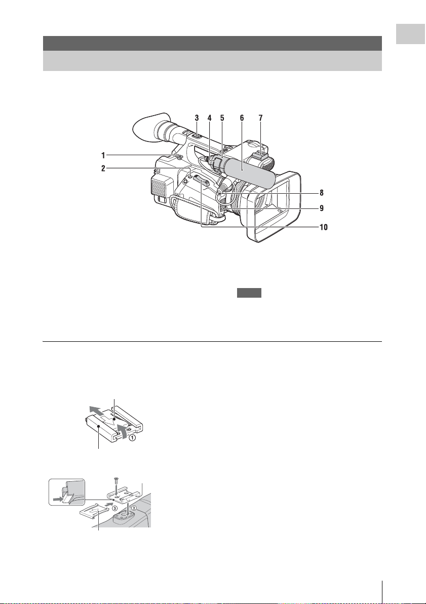
Location and Function of Parts
For functions and usage, see the pages in parentheses.
Overview
1. Hook for shoulder strap (8)
2. ASSIGN 7/FOCUS MAGNIFIER button
(33)
3. Accessory shoe mount
4. Microphone fixing clamper (16)
5. Microphone holder (16)
6. Microphone (16)
To mount the accessory shoe
Mount the accessory shoe on the accessory shoe
mount as illustrated.
Accessory shoe plate
Accessory shoe
Accessory shoe
Accessory shoe plate
7. Accessory shoe
8. IRIS PUSH AUTO button
9. Air inlet
Notes
• Areas around the exhaust vents may become hot.
• Do not cover the exhaust vents.
10. Power zoom lever (25)
1. Lift the edge of the accessory shoe plate and
pull it in the direction opposite to that of the
arrow on the accessory shoe plate and
remove it from the accessory shoe.
2. Place the accessory shoe as its protrusions
matches recesses of the accessory shoe
mount, then fix it to the mount with four
screws.
3. Insert the accessory shoe plate in the
direction of the arrow on the plate surface
until the end of the plate engages the end of
the shoe.
To remove the accessory shoe
Remove the shoe plate in the same way as step 1
of “To mount the accessory shoe.” Loosen the 4
screws and remove the accessory shoe from the
accessory shoe mount.
Location and Function of Parts
5
Page 6
Overview
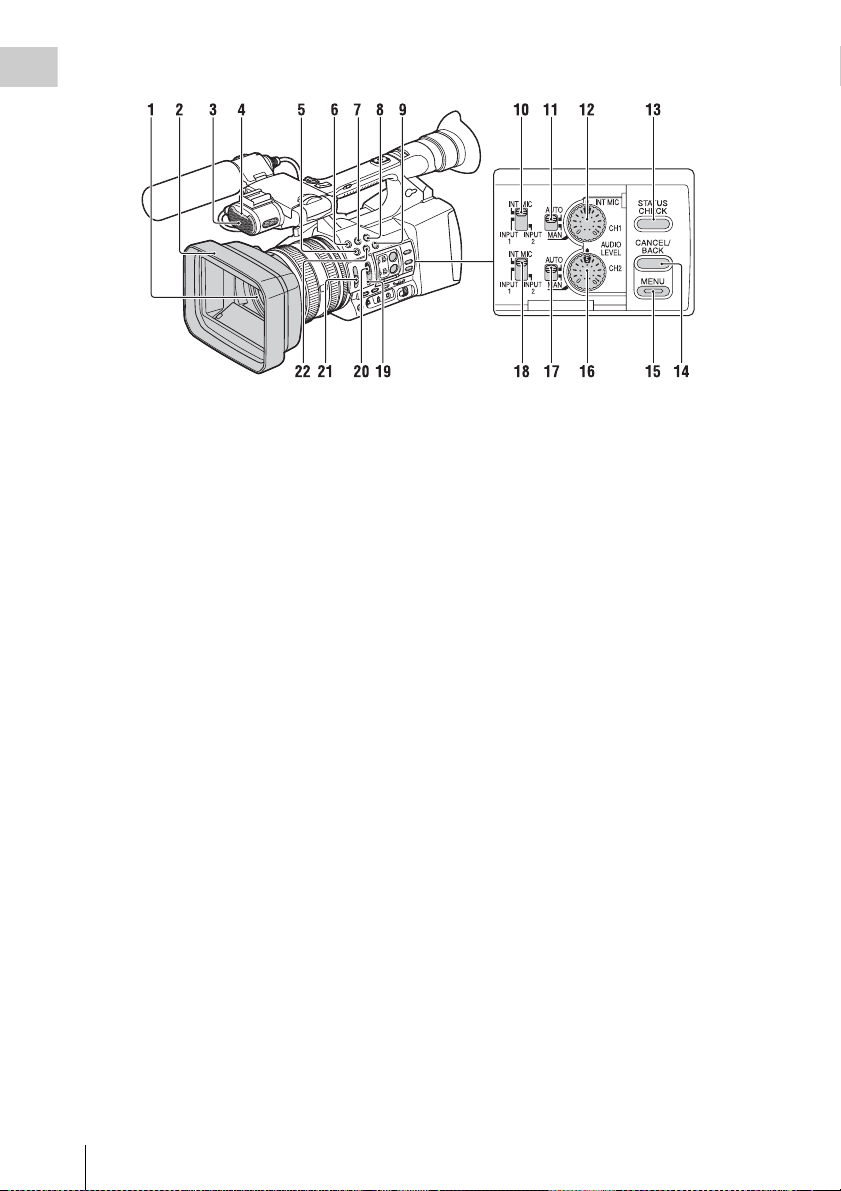
1. Lens (17)
2. Lens hood with lens cover (17)
3. Internal microphone (31)
4. Front recording lamp (49)
The recording lamp flashes if the remaining
capacity of recording media or battery is low.
5. ASSIGN 4/ZEBRA button
6. ASSIGN 1 button
7. ASSIGN 2 button*
8. ASSIGN 3 button
9. ASSIGN 6/THUMBNAIL button
10. CH1 (INT MIC/INPUT1/INPUT2) switch
11. AUTO/MAN (CH1) switch (32)
12. AUDIO LEVEL(CH1) dial (32)
13. STATUS CHECK button (9)
14. CANCEL/BACK button (39)
15. MENU button** (39)
16. AUDIO LEVEL(CH2) dial (32)
17. AUTO/MAN (CH2) switch (32)
18. CH2 (INT MIC/INPUT1/INPUT2) switch
(32)
19. PUSH AUTO button (26)
20. FOCUS switch (26)
21. ND FILTER switch (29)
22. ASSIGN 5/PEAKING button*
* The ASSIGN 5/PEAKING button and the ASSIGN 2
button have raised tactile dots for your convenience in
locating the button.
** MENU button has a raised tactile bar for your
convenience in locating the button.
Location and Function of Parts
6
Page 7
Overview
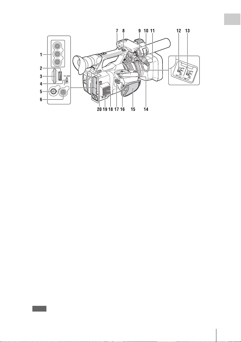
1. AUDIO OUT connectors/VIDEO OUT
connector (52, 63)
2. HDMI OUT connector (52)
3. UTILITY SD slot
(Used for storing and loading the settings
(File function), and to be supported by a
future upgrade (software update).)
4. TC LINK IN/OUT switch (32)
5. SDI OUT connector (52)
6. TC LINK connector
7. Handle zoom lever (25)
8. START/STOP button
When the lever is set to the HOLD position, the
START/STOP button is not operable.
9. INPUT2 connector
10. INPUT1 connector (16)
11. Cable holder (16)
Provided for securing a microphone cable, etc.
12. INPUT2 switch (31)
13. INPUT1 switch (31)
14. REMOTE connector
The REMOTE connector is used for controlling
start/stop of recording, etc., on the video device
and peripherals connected to it.
15. Grip belt
16. POWER switch (25)
17. Record button (25)
18. Air outlet
Notes
• Areas around the exhaust vents may become hot.
• Do not cover the exhaust vents.
19. DC IN connector (15)
20. Cable holder
Provided for securing a DC cable, etc.
Location and Function of Parts
7
Page 8
Overview
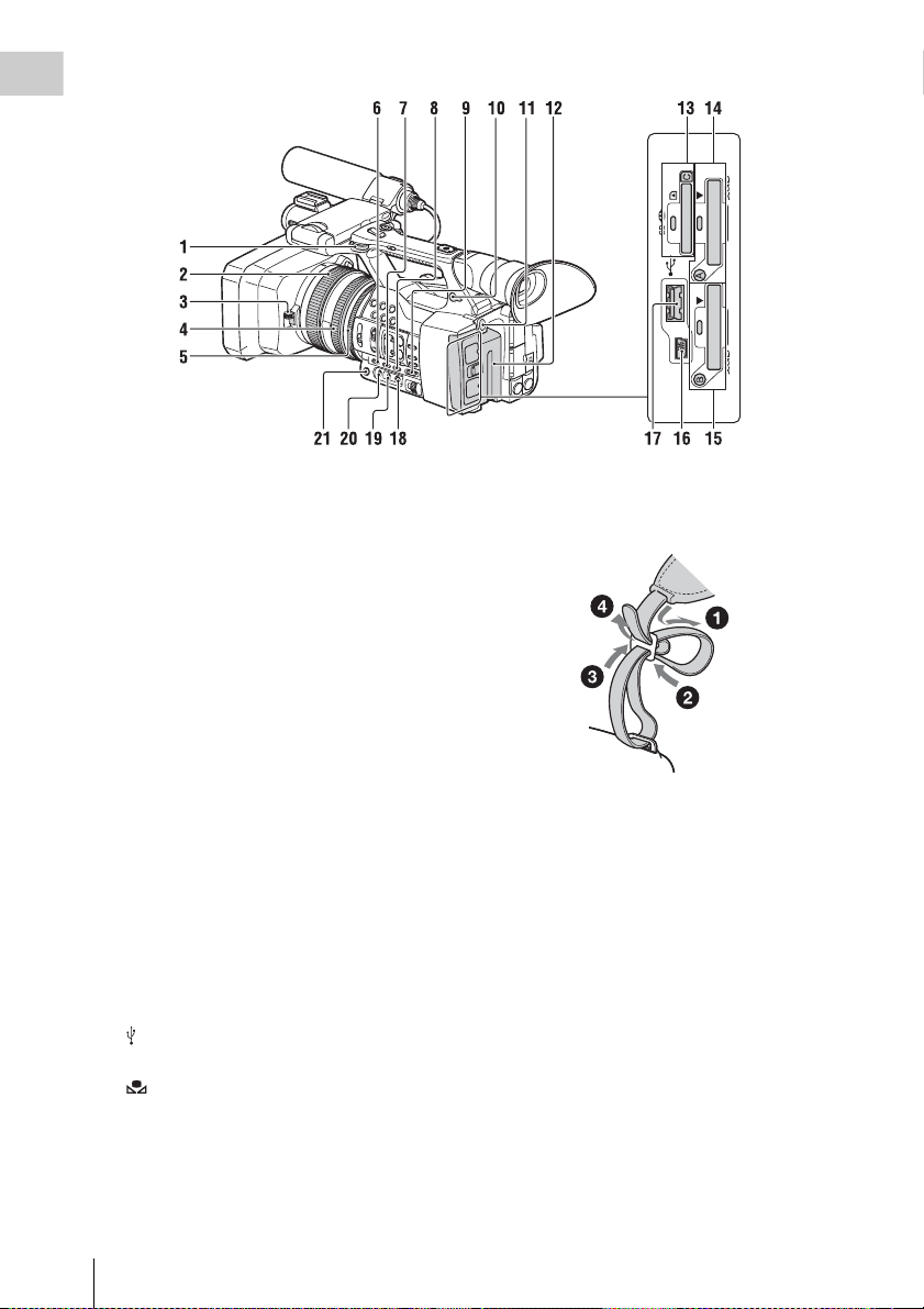
1. Hook for shoulder strap
2. Focus ring (26)
3. Lens cover lever (17)
4. Zoom ring (26)
5. Iris ring (28)
6. GAIN button (28)
7. WHT BAL button* (30)
8. SHUTTER SPEED button (29)
9. AUTO/MANUAL switch (28)
10. i (headphones) connector
For stereo mini-jack headphones
11. BATT RELEASE button (14)
12. Battery pack (14)
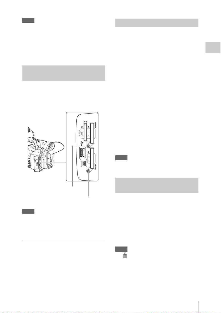
13. “Memory Stick” media/SD card C slot/
access lamp
(To be supported by future upgrade.)
14. XQD memory card A slot/select button/
access lamp (19)
15. XQD memory card B slot/select button/
access lamp (19)
16. USB connector (mini-B type) (53)
17. USB connector (A type)
(To be supported by future upgrade.)
18. (One push) button (29)
19. White balance memory switch (29)
20. Gain switch (28)
21. IRIS button* (28)
* WHT BAL and IRIS buttons have raised tactile dots
for your convenience in locating the buttons.
To attach a shoulder strap
Attach a shoulder strap (sold separately) to the
hooks for a shoulder strap.
Location and Function of Parts
8
Page 9
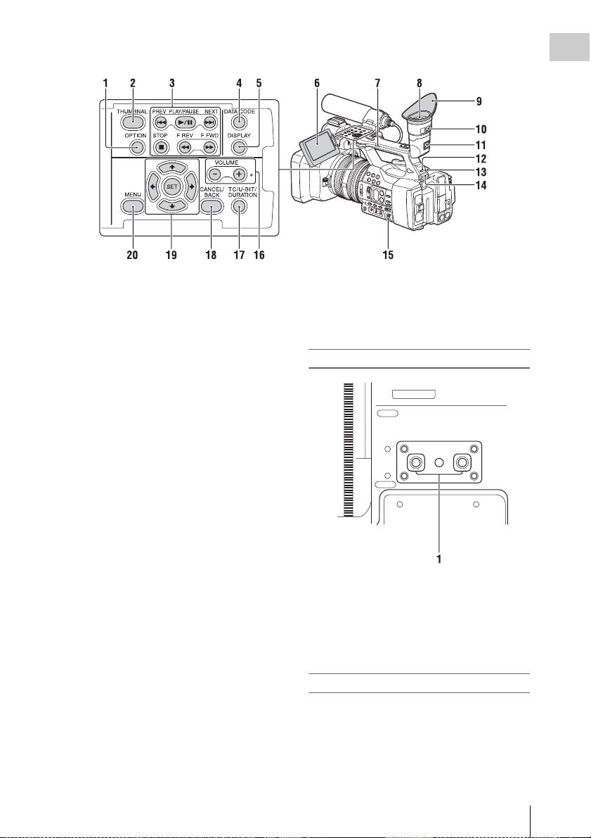
Overview
1. OPTION button (36)
2. THUMBNAIL button (35)
3. Playback control buttons (PREV, PLAY/
PAUSE*, NEXT, STOP, F REV, F FWD)
(27)
4. DATA CODE button
(To be supported by future upgrade.)
5. DISPLAY button (12)
6. LCD screen (17)
7. Handle zoom switch (25)
8. Viewfinder (18)
9. Large eyecup
10. Viewfinder lens adjustment lever (18)
11. Viewfinder release lever (59)
12. HEADPHONE MONITOR switch (32)
13. Rear recording lamp (49)
14. USB wireless LAN module retracting part
(20)
Connecting the supplied IFU-WLM3 USB
wireless LAN module (supplied) allows
communication with wireless LAN devices.
15. SEL/SET dial buttons (39)
16. VOLUME buttons*
17. TC/U-BIT/DURATION button
(To switch between the timecode and
recording time display on the LCD screen.
The user bit will be supported by a future
upgrade.)
18. CANCEL/BACK button (39)
19. V/v/B/b/SET buttons (39)
20. MENU button (39)
* VOLUME+ button and PLAY/PAUSE button have
raised tactile dots for your convenience in locating the
buttons.
Bottom
1. Tripod receptacle (1/4 inch)
This is a 1/4-20UNC screw compatible.
Attach a tripod (sold separately) to the tripod
receptacle using a tripod screw (sold
separately: the length of the screw must be
less than 5.5 mm (7/32 in.)).
Status screen
To display a status screen
• Press the STATUS CHECK button.
To switch status screens
• Turn the SEL/SET dial.
Location and Function of Parts
9
Page 10

To hide the status screen
Overview
• Press the STATUS CHECK button.
Camera status screen
Displays the electronic shutter settings or the
status of the lens.
Gain<H> Setting value of Gain <H>
Gain<M> Setting value of Gain <M>
Gain<L> Setting value of Gain <L>
Preset White Preset value of white balance
Gamma Gamma category and curve
AE Level Setting value of AE level
AE Speed Setting value of AE control
AGC Limit Setting value of the maximum
A.SHT Limit Fastest shutter speed of the
level
level
level
speed
gain of AGC
auto shutter function
Audio status screen
Displays the input settings for each channel,
audio level meter, and wind filter setting.
CH 1 level meter Level meter for CH 1
CH 1 Source Input source for CH 1
CH 1 Ref. / Sens. Sensitivity of the internal
CH 1 Wind Filter Setting status of the wind
CH 2 level meter Level meter for CH 2
CH 2 Source Input source for CH 2
CH 2 Ref. / Sens. Sensitivity of the internal
CH 2 Wind Filter Setting status of the wind
Audio Format Audio format setting
Headphone Out Headphone output setting
microphone input to CH 1, or
the reference level of audio
input
filter for the microphone input
to CH 1
microphone input to CH 2, or
the reference level of audio
input
filter for the microphone input
to CH 2
System status screen
Displays the video signal settings.
Country Setting status of the region,
Rec Format Recording format that is
Picture Size Picture size that is recorded on
NTSC region or PAL region
recorded on the XQD memory
card
the XQD memory card
Frame Rate Frame rate that is recorded on
Rec Function Special recording that is set to
the XQD memory card
on, and its setting value
Video output status screen
Displays the SDI, HDMI, and video output
settings.
SDI Output picture size
HDMI Output picture size
Video Output picture size
Output On/Off
Output On/Off
Assignable button status screen
Displays the function that is assigned to each
ASSIGN button.
1 Function that is assigned to
2 Function that is assigned to
3 Function that is assigned to
4 Function that is assigned to
5 Function that is assigned to
6 Function that is assigned to
7 Function that is assigned to
the Assign 1 button
the Assign 2 button
the Assign 3 button
the Assign 4 button
the Assign 5 button
the Assign 6 button
the Assign 7 button
Media status screen
Displays the remaining space, available
recording time, and estimated service life of the
recording media (XQD memory card A/XQD
memory card B).
Media
information of
Media A
Protect
information of
Media A
Media icon displayed when
recording media is inserted in
the slot A
Protect icon displayed when
recording media inserted in
the slot A is write-protected
Notes
• You cannot protect the XQD
memory card on the
camcorder.
Remaining meter
of Media A
Remaining
capacity of
Media A
Remaining capacity of the
recording media inserted in
the slot A, expressed with a
bar indicator
Remaining capacity of the
recording media inserted in
the slot A, expressed in GB
Location and Function of Parts
10
Page 11

Media
information of
Media B
Protect
information of
Media B
Remaining meter
of Media B
Remaining
capacity of
Media B
Media
information of
the UTILITY SD
card
Protect
information of
the UTILITY SD
card
Remaining meter
of the UTILITY
SD card
Remaining
capacity of the
UTILITY SD
card
Media icon displayed when
recording media is inserted in
the slot B
Protect icon displayed when
recording media inserted in
the slot B is write-protected
Remaining capacity of the
recording media inserted in
the slot B, expressed with a
bar indicator
Remaining capacity of the
recording media inserted in
the slot B, expressed in GB
Media icon displayed when
recording media is inserted in
the UTILITY SD slot
Protect icon displayed when
the UTILITY SD slot is writeprotected
Remaining capacity of the
recording media inserted in
the UTILITY SD slot,
expressed by a bar indicator
Remaining capacity of the
recording media inserted in
the UTILITY SD slot,
expressed in GB
Overview
Location and Function of Parts
11
Page 12
Overview
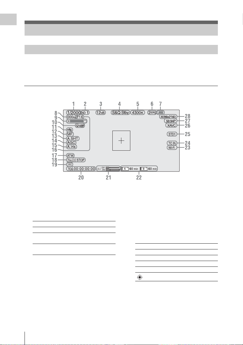
On-Screen Indications
LCD/viewfinder screen
While recording, standing by to record, or playback, the statuses and settings of this unit are superimposed
on the LCD/viewfinder screen.
The statuses and settings of this unit can be turned on/off using the DISPLAY button.
The statuses and settings of this unit can be independently turned on/off (page 46).
Information displayed on the screen while recording
1. Shutter mode/shutter speed indication
2. ND filter indication (page 29)
3. Gain indication (page 28)
4. Special recording/operation status
indication
zRec Recording in progress
Stby Standby for recording
zS&Q Rec Slow & Quick Motion
S&Q Stby Standby for Slow & Quick
recording in progress
Motion recording
5. Color temperature indication (page 29)
6.
S&Q motion frame rate indication
7. Battery remaining indication (page 57)
8. Focus position indication
Displays focus position.
9. Zoom position indication
Displays zoom position in the range of 0 (wide
position) to 99 (tele position)
10. Focus macro indication
On-Screen Indications
12
(page 47)
11. SteadyShot indication
12. Focus mode indication
13. Auto shutter indication
14. AGC indication
15. Auto iris indication
16. Iris position indication
Displays iris position.
17. White balance mode indication (page 29)
AT W Automatic mode
PWB Preset mode
Memory A Memory A mode
Memory B Memory B mode
n Preset mode (indoor)
Preset mode (outdoor)
18. Rec Control status of SDI output/HDMI
output indication (page 48)
19. UTILITY SD slot media status indication
20. Time data indication (page 32)
21. Audio level meter
Page 13
22. A/B slot media status/remaining space
indication (page 19)
When the left side of the icon is orange,
recording is possible.
When the green lamp on the upper right of the
icon lights, playback is possible.
23. Wi-Fi connection status indication
(page 20)
Displays the status when the Wi-Fi function is
on.
24. TC IN connection status indication
(page 47)
Displays the status when the timecode is input
from an external device.
25. Gamma indication (page 42)
Displays the gamma setting value.
26. Recording format (codec) indication
(page 28)
Displays the format that is recorded on an XQD
memory card.
27. System frequency and scan method
indication
28. Recording format (picture size) indication
(page 28)
Displays the picture size that is recorded on an
XQD memory card.
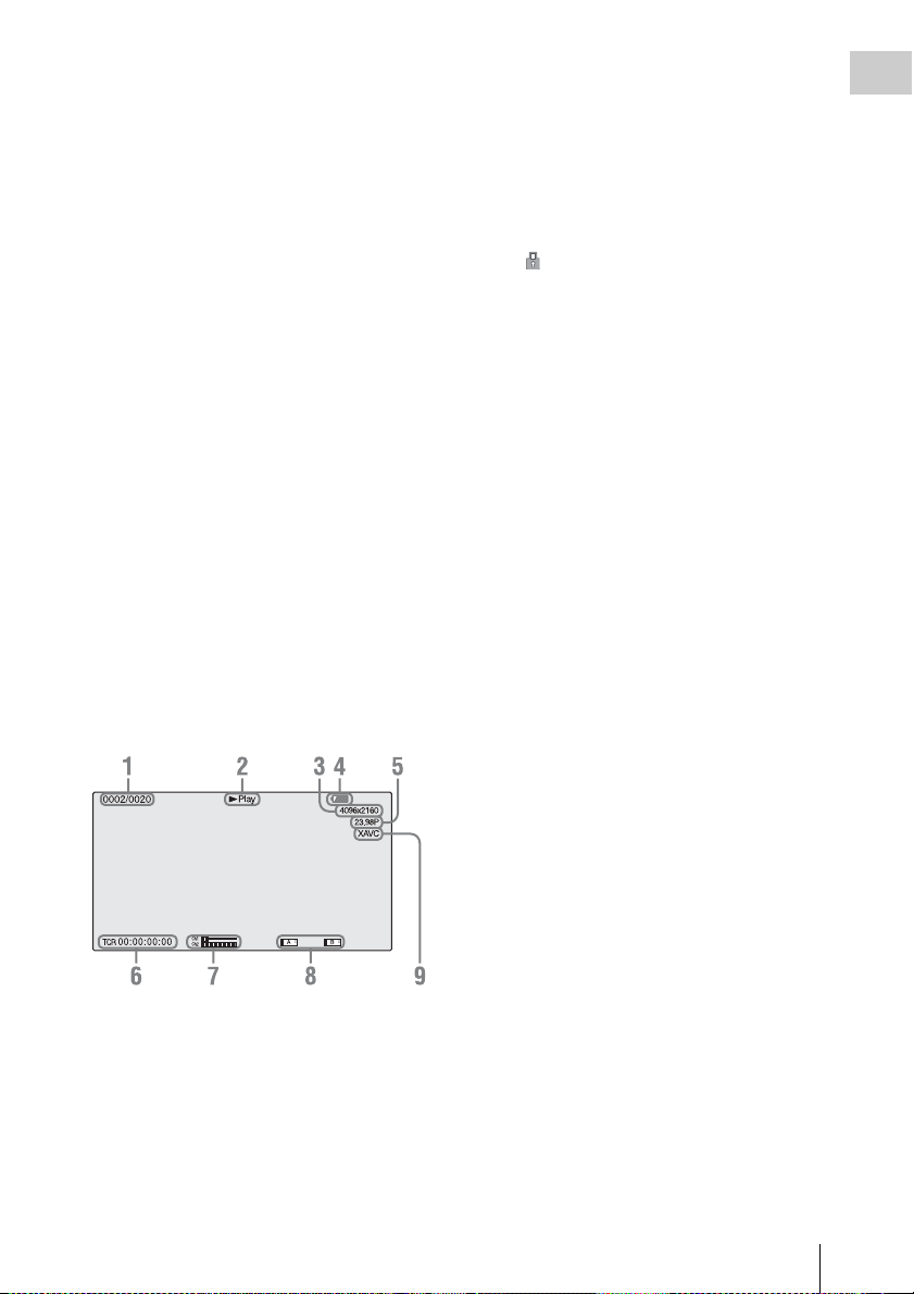
Information displayed on the playback screen
The following information is superimposed on
the playback picture.
6. Time data
The time data is displayed when the unit status/
settings are displayed by pre ssing the DISPLAY
button, and “Timecode” in “Display On/Off” of
the LCD/VF menu is set to “On.”
7. Audio levels
The audio levels for the recording are displayed.
8. Media
A mark appears to the left if the memory
card is write-protected.
9. Playback format (codec)
Overview
1. Clip no./total number of clips
2. Playback mode
3. Playback format (picture size)
4. Battery remaining
5. Playback format (frame rate)
On-Screen Indications
13
Page 14
Preparations
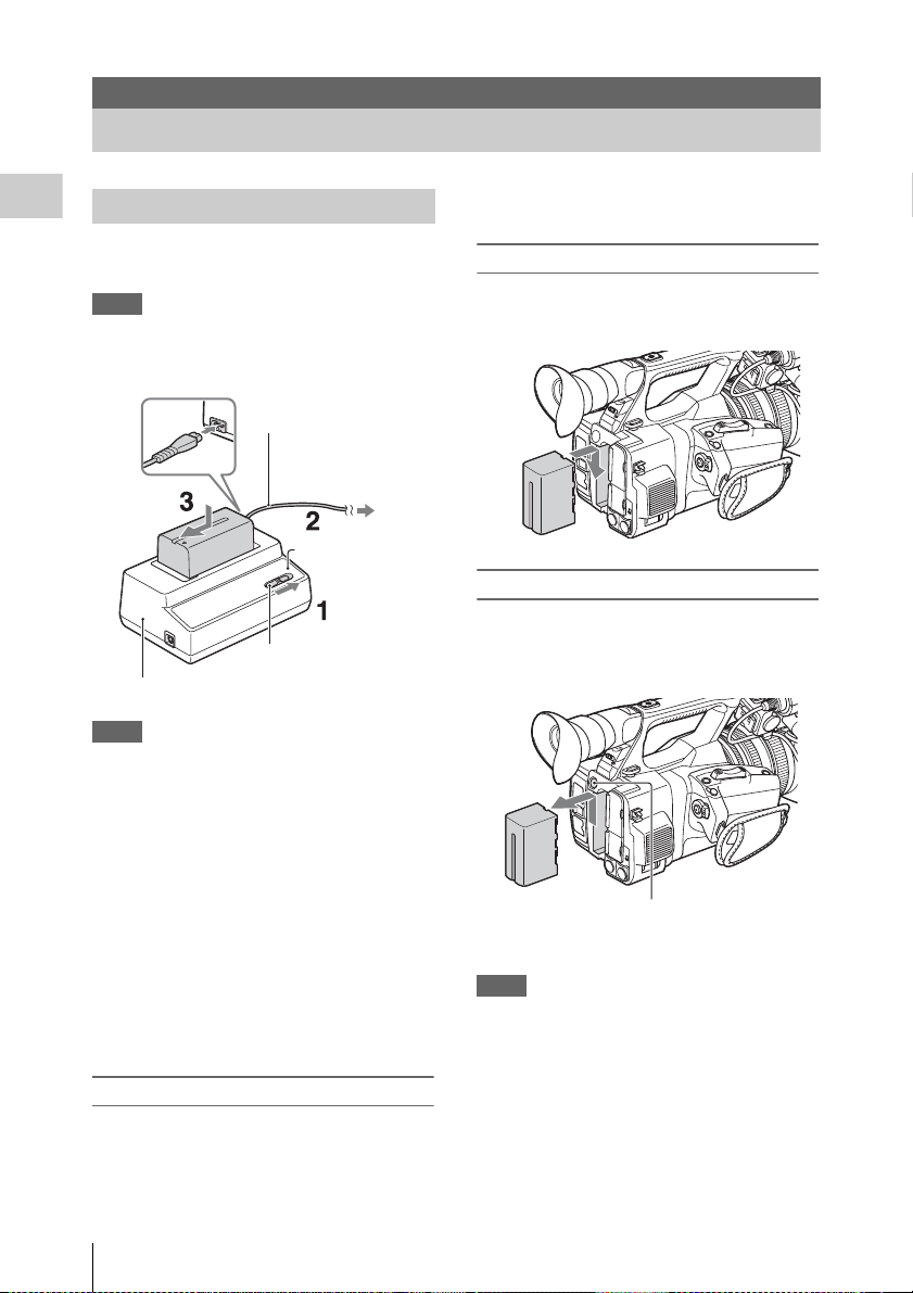
Power Supply
Charging the battery pack
Preparations
You can charge the “InfoLITHIUM” battery pack
(L series) with the supplied Charger.
Notes
• You can use a large capacity battery pack, NP-F970
(supplied), with your camcorder. You cannot use NPF570/F770 (sold separately).
Power cord
(mains lead)
To the wall outlet
(wall socket)
Charge lamp
Mode switch
Charger AC-VL1
Notes
• You cannot use the AC-VL1 to connect the camcorder
to an outside power source. When you connect the
camcorder to a wall outlet (wall socket), use the
supplied AC Adaptor.
Remove the battery pack from the Charger when
the charge is completed.
Attaching the battery pack
Press the battery pack against the back of your
camcorder and slide it down.
Removing the battery pack
Slide the POWER switch to OFF. Push the BATT
RELEASE (battery release) button and remove
the battery pack.
1 Set the mode switch to CHARGE.
2 Connect the power cord (mains lead) to
the Charger and the wall outlet (wall
socket).
3 Place the battery pack in the slot of the
Charger, press it down, and slide it in
the direction of the arrow.
The charge lamp turns on and charging starts.
After charging the battery
The charge lamp turns off (normal charge). If you
continue charging 1 more hour after the charge
lamp turns off, you can use the battery a little
longer (full charge).
Power Supply
14
BATT RELEASE
(battery release) button
Notes
• Settings of the menu or settings adjusted using the
AUTO/MANUAL switch can be saved when the
POWER switch is set to OFF. Remov e the battery pack
after the display on the LCD/viewfinder screen has
completely disappeared. Otherwise, changed settings
may not be saved.
• If you remove the battery pack or AC Adaptor wit h the
POWER switch ON, you cannot turn the camcorder on
even though you attach the battery pack or AC Adaptor
again.
Slide the POWER switch to OFF temporarily, then to
ON.
Page 15
Storing the battery pack
If the battery pack is not in use for a while, run
down the battery and store it. See page 57 for
details on storage of the battery pack.
Charging time
Approximate time (minute) required when you
charge a fully discharged battery pack.
Battery pack
NP-F970 365 425
Notes
• You cannot use the NP-F570/NP-F770 battery pack
with your camcorder.
Normal charge
time
Full charge time
On the battery pack
• Before changing the battery pack, slide the POWER
switch to OFF.
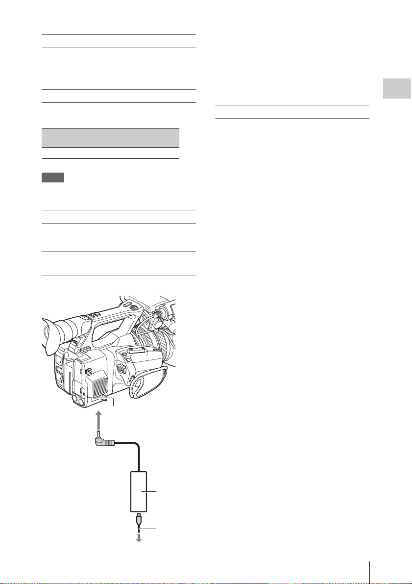
Using a wall outlet (wall socket) as a
power source
You can use the AC Adaptor to obtain AC power.
1. Connect the power cord (mains lead) to the
AC Adaptor.
2. Connect the AC Adaptor to the DC IN jack of
the camcorder.
3. Connect the power cord (mains lead) to the
wall outlet (wall socket).
Preparations
On the AC Adaptor
• Use the nearby wall outlet (wall socket) when
using the AC Adaptor. Disconnect the AC
Adaptor from the wall outlet (wall socket)
immediately if any malfunction occurs while
using your camcorder.
• Do not use the AC Adaptor placed in a narrow
space, such as between a wall and furniture.
• Do not short-circuit the plug of the AC Adaptor
with any metallic objects. This may cause a
malfunction.
• Even if your camcorder is turned off, AC power
(house current) is still supplied to it while
connected to t he wall outlet (wall sock et) via the
AC Adaptor.
• You cannot charge the camcorder by
connecting it to the AC Adaptor.
DC IN
connector
To the wall outlet
(wall socket)
AC
Adaptor
ACNB12A
Power
cord
(mains
lead)
Power Supply
15
Page 16
Setting the Clock Attaching Devices
When you turn the camcorder on for the first time
after purchasing or the backup battery has
completely discharged, the Initial Setting display
Preparations
appears on the viewfinder screen and LCD
screen. Set the date and time of the built-in clock,
using this display.
Time Zone
The value shows the time difference from UTC
(Coordinated Universal Time).
Change the setting if needed.
Setting the time and date
Clock starts after you turn the SEL/SET dial
(page 9) to select the items or value, then press
the SEL/SET dial to set them.
After the setting display disappears, “Clock Set”
(page 50) in the System menu can be used to set
“Time Zone” and date/time.
Notes
• If the clock setting is cleared because the backup
battery fully discharged when no power was supplied
(no battery pack and no DC IN connection), the Initial
Setting display will be displayed when you next turn
the camcorder on.
• While the Initial Setting display is shown, no other
operation, except turning the power off, is permitted
until you finish the setting for this display.
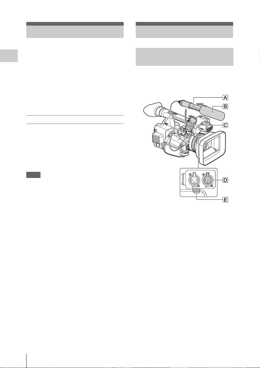
Attaching the supplied microphone
When you use the supplied microphone (ECMXM1) for recording sound, do the following
steps.
1 Attach the wind screen B to the
supplied microphone A.
2 Place the microphone A in the
microphone holder C with the model
name facing upward, close the cover,
and shut the clamper.
Setting the Clock / Attaching Devices
16
3 Connect the plug of the microphone to
the INPUT1 connector D.
4 Put the microphone cable into the cable
holder E.
Page 17
Hook the cable in the outer cable holder.
Attaching the lens hood with lens cover
PUSH (lens hood release) button
Removing the lens hood with lens cover
Turn the lens hood in the opposite direction to the
arrow 2 in the illustration while pressing the
PUSH (lens hood release) button.
Notes
• Remove the lens hood with lens cover when you
attach/detach a 72mm polarized filter or protective
filter.
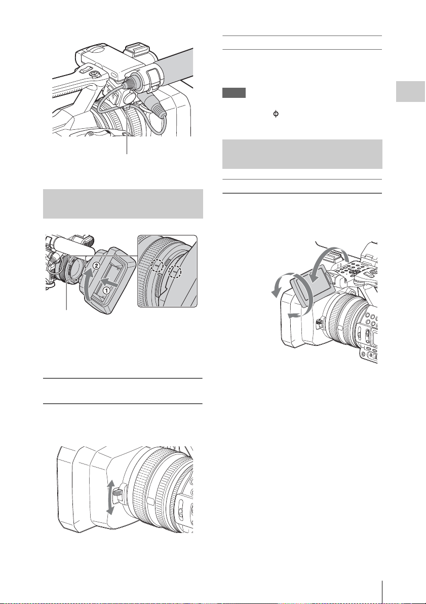
Adjusting the LCD screen and viewfinder
LCD screen
Open the LCD screen 180 degrees (1), then
rotate it to the best angle to record or play back
(2).
1Open 180 degrees.
290 degrees
(max.)
2180 degrees
(max.)
Preparations
Align the marks on the lens hood to those on
the camcorder, and turn the lens hood in the
direction of the arrow 2 until it is locked.
Opening or closing the shutter of the lens
hood with lens cover
Move the lens cover lever to OPEN to open the
lens cover, and move the lever to CLOSE to close
the lens cover.
• Images are displayed as mirror images on the
LCD screen, but are recorded as normal images.
• You can switch the brightness of the backlight
of the LCD screen with “LCD Backlight” of
“LCD Setting” in the LCD/VF menu (page 44).
Attaching Devices
17
Page 18
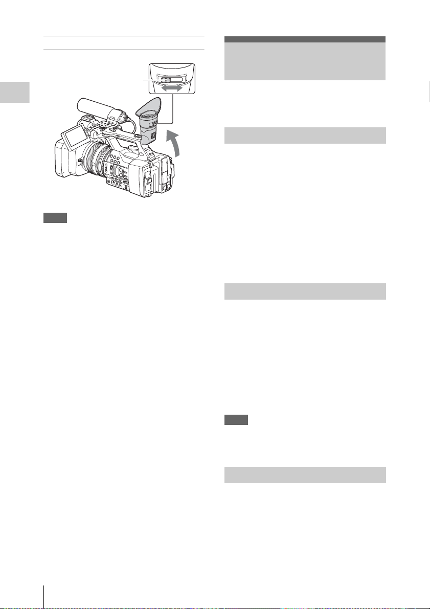
Viewfinder
Viewfinder lens
adjustment lever
Move it until the picture
becomes clear.
Preparations
Notes
• You may see primary colors shimmering in the
viewfinder when you move your line of sight. This is
not a malfunction. The shimmering colors will not be
recorded on the recording media.
You can switch the brightness of the viewfinder
backlight with “VF Backlight” of “VF Setting” in
the LCD/VF menu (page 44).
Using XQD Memory Cards
This camcorder records audio and video on XQD
memory cards inserted in the card slots.
About XQD memory cards
Use the following Sony XQD memory cards.
XQD memory card S series (R/W: 180MB/s*)
* Use an XQD memory card with a description of Read /
Write 180 MB/s.
You cannot use other XQD memory cards.
Operations are not guaranteed with other memory
cards.
For details on using XQD memory cards and usagerelated precautions, refer to the instruction manual
for the XQD memory card.
Inserting an XQD memory card
1 Open the cover of the card slot block.
2 Insert the XQD memory card until it
clicks into place with the XQD label
facing to the left.
The access lamp (page 8) lights in red then
changes to green once the memory card is
ready for use.
Using XQD Memory Cards
18
3 Close the cover.
Notes
• If you insert a memory card into the slot in the wrong
direction, the memory card, the memory card slot, or
image data may be damaged.
Removing an XQD memory card
Open the cover of the card slot block,
remove the XQD memory card by pressing
the XQD memory card once lightly.
Page 19
Notes
• Data integrity is not guaranteed if the power is turned
off or a memory card is removed while it is being
accessed. Data on the card may be destroyed. Be sure
that its access lamp is lit in green or off when you turn
off the power or remove a memory card.
• An XQD memory card removed from the camcorder
after recording ended may be hot. This is not a
malfunction.
Selecting the memory card slot to be used for recording
Press the A or B button of the memory card slot
where the memory card you want to record on is
inserted. The lamp of the selected slot lights up in
green.
Formatting an XQD memory card
If an XQD memory card is not formatted, or was
formatted with another system, the message
“Media Needs to be Formatted” is displayed on
the LCD/viewfinder screen.
Format the card as follows.
Using “Format Media” (page 48) in the
Media menu, specify “Media(A)” (slot A) or
“Media(B)” (slot B) then select “Execute.”
On a confirmation message, select
“Execute” again.
The in-progress message and status bar are
displayed, and the access lamp lights in red.
When formatting is complete, a completion
message is displayed. Press the SEL/SET dial to
hide the message.
If formatting fails
A write-protected XQD memory card or memory
card that cannot be used with this camcorder will
not be formatted.
As a warning message is displayed, replace the
card with an appropriate XQD memory card,
according to the instructions in the message.
Notes
• All the data, including recorded pictures and setup
files, are erased when a memory card is formatted.
Preparations
Memory card slot A button
Memory card slot B button
Notes
• You can only select a slot that already has a memory
card inserted.
• While movies are being recorded on the memory card,
you cannot switch the slot even if you press the
memory card slot A/B buttons.
• When only one slot has a memory card inserted,
the slot that has the memory card is selected
automatically.
• If the memory card is fully recorded during
recording, the camcorder continues recording
automatically on the memory card inserted in
the other slot.
Checking the remaining time available for recording
While recording (or standing by to record), you
can check the remaining space for the XQD
memory cards loaded in the card slots on the A/B
slot media status/remaining space indication of
the LCD screen/viewfinder screen (page 12).
The available time for recording with the current
video format (recording bit rate) is calculated
according to the remaining space of each card and
displayed in time units of minutes.
Notes
• A icon appears if the memory card is writeprotected.
Using XQD Memory Cards
19
Page 20

Replacing an XQD memory card
• If the available time on two cards in total
becomes less than 5 minutes, the warning
message “Media Near Full” is displayed, the
recording lamp flashes, and a beep sound is
output to the headphones to warn you. Replace
Preparations
the cards with those that have sufficient space.
• If you continue recording until the total
remaining time reaches zero, the message
changes to “Media Full,” and recording stops.
Notes
• Up to approximately 600 clips can be recorded on one
XQD memory card.
If the number of recorded clips reaches the limit, the
remaining time indication becomes “0,” and the
message “Media Full” is displayed.
Using a USB Wireless LAN Module
You can make the Wi-Fi connection between the
camcorder and a device such as a smartphone,
tablet, etc., by attaching the supplied IFU-WLM3
USB wireless LAN module.
Notes
• You cannot use a USB wireless LAN module other
than the IFU-WLM3.
Making a Wi-Fi connection between a device and
the camcorder enables you to do the following.
• Record and playback the camcorder
• Display the current status of the camcorder
• Switch between the recording settings and
system settings
• Operate the assignable buttons of the camcorder
• Operate the iris, focus and zoom
Attaching the IFU-WLM3
1 Open the cover of the USB wireless
LAN module retracting part (page 9).
2 Insert the IFU-WLM3 to the USB
connector.
Using a USB Wireless LAN Module
20
3 Close the cover.
Notes
• The IFU-WLM3 cannot be removed easily once
attached. Use with the IFU-WLM3 attached.
Making a Wi-Fi connection
Notes
• Only one Wi-Fi device can be connected at a time.
Making a network setting
Change the “Basic Authentication” settings
(page 50) of the System menu as required.
Item Setting
User Name User name for log-in (factory default
Password Password for log-in (factory default
setting: “admin”)
setting: model name “pxw-z100”)
Page 21
For details about the menu settings and entering a
character string, see “Setup Menu Operations”
(page 39).
Making a connection
1 Set “Wi-Fi” in “Wi-Fi” (page 50) of the
System menu to “Enable.”
2 Make a Wi-Fi connection by inputting
the SSID and Password onto the device,
or by using the Wi-Fi direct connection
function.
You can check the SSID and password of the
camcorder on “SSID & Password” in “WiFi” (page 50) of the System menu.
When using the Wi-Fi direct connection
function, proceed to the following step.
3 Select “Execute” for “Wi-Fi Direct
Connection” in “Wi-Fi” of the System
menu.
The setup menu disappears, and the
connection wait message for the Wi-Fi direct
connection function appears.
Using the Push-Button method
When you perform the Push-Button method
on the device, the message for connection
permission appears on the connection wait
screen. Select “Execute.”
Using the PIN code method
When you perform the PIN code method on
the device, the device name and PIN code
appears on the connection wait screen.
Complete the connecting process by
inputting the PIN code to the device.
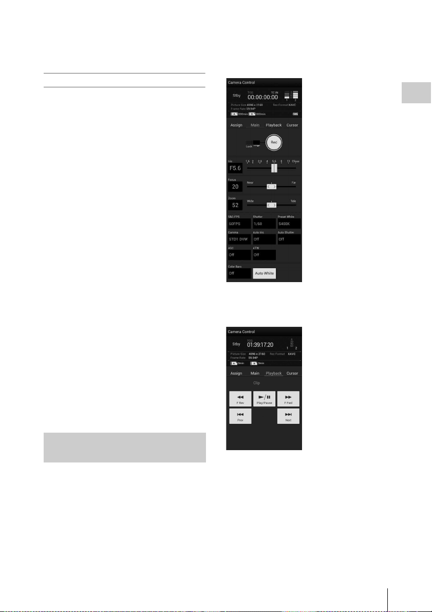
Wi-Fi remote commander displays
Smartphone
Main screen
• Recording settings
indication:
S&Q FPS, Shutter,
Preset White, Gamma,
Auto Iris, Auto
Shutter, AGC, ATW,
Color Bars, Auto
White
Playback screen
• Status indication
• Playback operation
button:
F Rev, Play/Pause,
F Fwd, Prev, Stop,
Next
Preparations
Using the Wi-Fi remote commander
When a Wi-Fi connection is established between
a device such as smartphone, tablet, etc., and the
camcorder, the Wi-Fi remote commander appears
on the device screen and the device can be used as
a remote commander.
You can start/stop recording and adjust the
recording settings with a Wi-Fi connected device.
This function is useful for setting the camcorder
in a remote place, such as the top of a crane, etc.
Using a USB Wireless LAN Module
21
Page 22
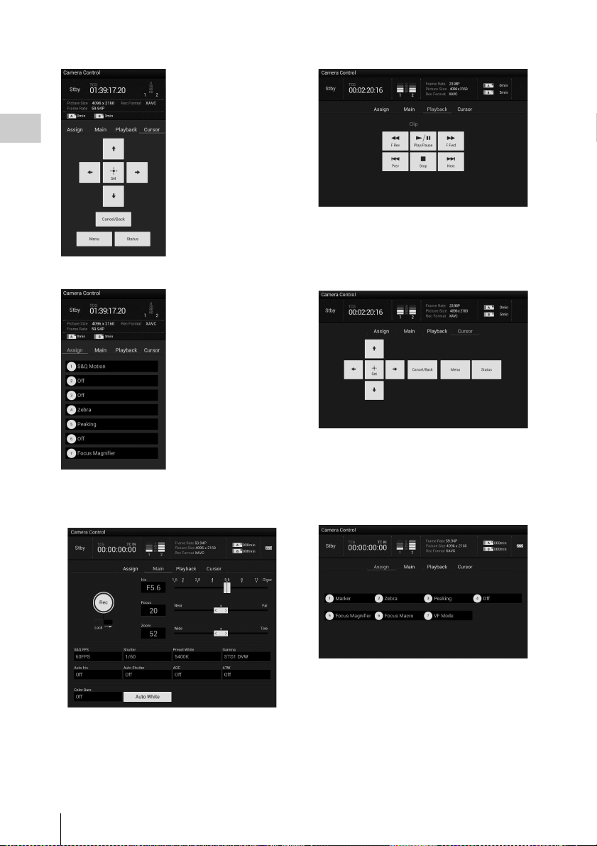
Preparations
Cursor screen
Assign screen
Tablet
Main screen
• Status indication
• Cursor operation
button, menu/status
indication:
Up, Left, Set, Right,
Down, Cancel/Back,
Menu, Status
• Status indication
• Assignable button
indication:
Assignable buttons 1
to 7
Playback screen
• Status indication
• Assignable button indication
• Playback operation button:
F Rev, Play/Pause, F Fwd, Prev, Stop, Next
Cursor screen
• Status indication
• Assignable button indication:
• Cursor operation button, menu/status indication:
Up, Left, Set, Right, Down, Cancel/Back, Menu,
Status
Assign screen
• Assignable button indication:
Assignable buttons 1 to 7
• Recording settings indication:
S&Q FPS, Shutter, Preset White, Gamma, Auto Iris,
Auto Shutter, AGC, ATW, Color Bars, Auto White
Using a USB Wireless LAN Module
22
• Assignable button indication:
Assignable buttons 1 to 7
Page 23

Displaying the Wi-Fi remote commander
The display size of the Wi-Fi remote commander
changes according to the device screen size
automatically.
1 Make a Wi-Fi connection between the
device and camcorder (page 20).
2 Launch the browser and input http://
<camcorder’s IP address> (“System
menu” > “Wi-Fi” > “IP Address”)/
rm.html in the address bar.
Example: When the IP address is 10.0.0.1,
input http://10.0.0.1/rm.html in the address
bar.
3 Input the user name and password
(“System menu” > “Basic
Authentication” > “User Name” or
“Password”) on the browser.
When completing the connection, the display
of the Wi-Fi remote commander appears on
the device.
Operate the Wi-Fi remote commander by
following the display.
The REC button becomes unavailable when
the Lock switch is dragged to the right.
Notes
• Depending on the device, the Wi-Fi remote
commander may not appear properly on the device’s
screen even though you input http://<camcorder’s IP
address>/rm.html in the address bar. In this case, input
“rms.html” for a smartphone or “rmt.html” for a tablet
instead of “rm.html” at the end of the address to
display the Wi-Fi remote commander properly.
• The Wi-Fi remote commander on the device’s screen
may no longer match the actual status of the camcorder
in the following cases. When this happens, refresh the
browser on the device.
—when the camcorder is restarted while the Wi-Fi
connection is established
—when the camcorder is controlled directly while
the Wi-Fi connection is established
—when the device is reconnected
—when you operate forward/backward on the
device’s browser.
• If the Wi-Fi signal is poor, the Wi-Fi remote
commander may not work properly.
Device OS Browser
Smartphone Android 4.0/4.1/
4.2
iOS 5
iOS 6
Tablet Android 4.0/4.1/
4.2
iOS 5
iOS 6
Chrome V26
Safari 5
Safari 6
Chrome V26
Safari 5
Safari 6
Preparations
Compatible devices
The following devices, using the specified
versions or higher, can be used as Wi-Fi remote
commanders.
Using a USB Wireless LAN Module
23
Page 24

Using a UTILITY SD card
You can store the setting value file of the camera
on an SD card (optional). The stored file can be
loaded from the SD card.
Preparations
Usable SD Cards
SDHC memory card* (Speed Class: 4 to 10,
UHS is not compatible, Capacity: 2 GB to 32 GB)
SD memory card* (File system: FAT 16,
Capacity: up to 2 GB)
* Indicated as “SD card” in these Operating Instructions.
It is also necessary to format an SD memory card
if a caution message is displayed when you mount
it.
Using “Format Media” (page 48) in the
Media menu, specify “SD card” then select
“Execute.” On a confirmation message,
select “Execute” again.
The in-progress message and status bar are
displayed, and the access lamp lights in red.
When formatting is complete, a completion
message is displayed. Press the SEL/SET dial to
hide the message.
Notes
• All the data are erased when a memory card is
formatted, and the data cannot be restored.
Inserting an SD Card
1 Open the cover of the UTILITY SD/
HDMI (page 7).
2 Insert the UTILITY SD memory card
into the slot with the UTILITY SD label
facing right.
The access lamp (page 8) lights in red then
turns off when the memory card is ready for
use.
3 Close the cover.
Removing an SD memory card
Open the cover of the card slot block,
remove the SD card by pressing the SD card
once lightly.
Notes
• Data integrity is not guaranteed if the power is turned
off or a memory card is removed while it is being
accessed. Data on the card may be destroyed. Be sure
that its access lamp is off before you turn off the power
or remove a memory card.
• Make sure that the card does not pop out when
inserting or removing it.
Checking the Remaining Time
The remaining time can be checked on the media
status screen (page 10).
Notes
• A icon appears if the memory card is writeprotected.
To use media formatted with this camcorder in
the slots of other devices
Make a backup of the media, then format it using
the other device.
Formatting an SD Memory Card
When you use an SD memory card with this
camcorder, it must be formatted using the format
function of this camcorder.
Using a UTILITY SD card
24
Page 25

Recording
Basic Operation Procedure
Basic recording can be performed with the
following procedures.
1 Make sure that the necessary devices
are attached to the camcorder and
power is supplied to them.
2 Load the memory card(s).
If you load two cards, recording is continued
by automatically switching to the second
card when the first card becomes full.
3 Open the shutter of the lens hood with
lens cover.
4 Slide the POWER switch to ON while
pressing the green button.
The recording screen is displayed on the
LCD/viewfinder screen.
5 Press the record button (page 7).
The recording lamp lights and recording
begins.
6 To stop recording, press the record
button again.
Recording stops and the camcorder enters
STBY (recording standby) mode.
Adjusting the zoom
To use the power zoom lever
Move the power zoom lever D slightly for a
slower zoom. Move it further for a faster zoom.
Wide view: (Wide angle)
Recording
Close view: (Telephoto)
• The minimum distance required between your
camcorder and the subject for focus is about
1 cm (about 13/32 in.) for wide angle and about
80 cm (about 2 5/8 feet) for telephoto.
• The focus may not be adjusted at certain zoom
positions if the subject is within 80 cm (about
2 5/8 feet) from your camcorder.
• When “Focus Macro” in “Focus” of Camera
menu is set to “Off,” you cannot focus on a
subject within 80 cm (about 2 5/8 feet)
regardless of the zoom position (page 40).
• Be sure to keep your finger on the power zoom
lever D. If you move your finger off the power
zoom lever D, the operation sound of the
power zoom lever D may also be recorded.
• You can change the zoom speed of the power
zoom lever D or the handle zoom lever A on
“Setting” in “Speed Zoom” of the Camera menu
(page 41).
To use the handle zoom
1. Set the handle zoom switch B to VAR or
FIX.
• When you set the handle zoom switch B
to VAR, you can zoom in or out at variable
speed.
• When you set the handle zoom switch B
to FIX, you can zoom in or out at fixed
speed, as set in “Setting” in “Handle
Zoom” of the Camera menu (page 41).
2. Press the handle zoom lever A to zoom in or
out.
Basic Operation Procedure
25
Page 26

Notes
• You cannot use the handle zoom lever A when the
handle zoom switch B is set to OFF.
• You cannot change the zoom speed of the power zoom
lever D with the handle zoom switch
Using the zoom ring
You can zoom at the desired speed by turning the
zoom ring C. Fine adjustment is also possible.
Notes
• Turn the zoom ring C at a moderate speed. If you turn
it too fast, the zoom speed may lag behind the zoom
ring rotation speed, or the operation sound of the zoom
may also be recorded.
Recording
Adjusting the focus manually
You can adjust the focus manually for different
recording conditions.
Use this function in the following cases.
—To record a subject behind a window
covered with raindrops.
—To record horizontal stripes.
—To record a subject with little contrast
between the subject and its background.
—When you want to focus on a subject in the
background.
—To record a stationary subject using a
tripod.
B.
1 During recording or standby, set the
FOCUS switch B to MAN.
The focus mode indication changes to “MF.”
2 Rotate the focus ring A and adjust the
focus.
For focusing manually
• It is easier to focus on the subject when you use
the zoom function. Move the power zoom lever
towards T (tel ephoto) and adjust the foc us, then,
towards W (wide angle) to adjust the zoom for
recording.
• When you want to record a close-up image of a
subject, move the power zoom lever towards W
(wide angle) to fully magnify the image, then
adjust the focus.
To restore automatic adjustment
Set the FOCUS switch B to AUTO.
The focus mode indication changes to “AF” and
the automatic focus adjustment is restored.
To use automatic focus temporarily
(Push auto focus)
Record the subject while pressing and holding the
PUSH AUTO button C.
If you release the button, the setting returns to
manual focusing.
Use this function to shift the focus on one subject
to another. The scenes will shift smoothly.
• The focal distance information (for when it is
dark and hard to adjust the focus) appears for
about 3 seconds in the following cases. (It will
not be displayed correctly if you are using a
conversion lens (sold separately)).
—When you rotate the focus ring while “MF”
is displayed on the screen
To use the expanded focus (Expanded focus)
In the default setting, “Focus Magnifier” is
assigned to the ASSIGN 7 button (page 33).
Press the ASSIGN 7 button.
The focus mag nifier screen appears and the center
of the screen is magnified by about 2.0 times. It
will be easier to confirm the focus setting during
manual focusing. The screen returns to the
original size when you press the button again.
Notes
• Even though the image appears expanded on the
screen, the recorded image is not expanded.
Basic Operation Procedure
26
Page 27

Playing a recorded clip
You can play the recorded clip while the
camcorder is in standby mode.
1 Insert the XQD memory card.
2 Press the PLAY/PAUSE button of the
playback control buttons.
3 Search for the desired clip by pressing
PREV or NEXT button.
4 Press the PLAY/PAUSE button.
The playback image appears on the
viewfinder.
Playback operation is performed as follows.
PLAY/PAUSE button: Pauses playback. To
resume playback, press this button again.
F FWD button/F REV button: Plays fast. To
return to normal playback, press the PLAY/
PAUSE button.
STOP button: Stops playback or recording.
Monitoring audio
In normal playback mode, you can monitor the
recorded audio signals through the connected
headphones.
You can select audio channel to be monitored and
adjust the sound volume with “Audio Output”
(page 43) in the Audio menu.
Clip (recording data)
When you stop recording, video, audio and
subsidiary data from the start to end of the
recording are recorded as a single clip on an
XQD memory card.
Clip name
For each clip recorded with this camcorder, a
clip name is automatically generated as “Clip” +
a four-digit number.
The number is automatically incremented.
Maximum duration of a clip
The maximum clip length is 13 hours.
The maximum continuous recording time for a
movie is approximately 13 hours. If recording
time reaches approximately 13 hours, the
recording will stop.
Recording
Cueing Up
To start playback from the top of the clip
Press the PREV button or NEXT button of the
playback contro l buttons (page 9). You can cue to
the top of a desired clip by pressing either button
repeatedly.
Switching the XQD memory cards
When two memory cards are loaded, press the
select button (page 8) to switch memory cards.
Notes
• You cannot switch XQD memory cards during
playback.
Continuous playback of cards in slots A and B is not
possible.
Basic Operation Procedure
27
Page 28

Changing Basic Settings
You can make changes to the settings based on
the intended usage of the recorded video or
recording conditions.
Recording format
Selectable format depends on the setting of the
region where the camcorder is used (Country).
Recording
To change the format, use “Video Format” in
“Rec Format” (page 49) of the System menu.
Adjusting the image brightness
1. During recording or standby, set the AUTO/
MANUAL switch H to MANUAL.
2. When the iris is automatically adjusted, press
the IRIS button E.
The iris value appears. When the iris value is
automatically adjusted, “A.Iris” is displayed.
3. Adjust the iris with the iris ring A.
• The F value becomes close to F3.4 as the zoom
position changes from W to T even when you
open the aperture by setting the F value lower
than F3.4, such as F1.6.
• The range of focus, an important effect of the
aperture, is called the depth of field. The depth
of field gets shallower as the aperture is opened,
and deeper as the aperture is closed. Use the
aperture creatively to obtain the desired effect
in your photography.
• This is handy for making the background
blurred or sharp.
To adjust the iris automatically
Press the IRIS button E, or set the AUTO/
MANUAL switch H to AUTO.
“A.Iris” is displayed next to the iris value.
Notes
• When you set the AUTO/MANUAL switch H to
AUTO, other manually adjusted items (gain, shutter
speed, white balance) also become automatic.
You can adjust the image brightness by adjusting
the iris, gain or shutter speed, or by reducing the
light volume with the ND FILTER switch B.
Adjusting the iris
You can manually adjust the iris to control the
volume of the light entering the lens. By adjusting
the iris, you can change or close ( ) the
aperture of the lens, which is expressed as an F
value between F1.6 and F11. The volume of the
light increases the more that you open the
aperture (decreasing F value). The volume of the
light decreases the more that you close the
aperture (increasing F value). The current F value
appears on the screen.
Changing Basic Settings
28
Adjusting the gain
You can adjust the gain manually when you do
not want to use the AGC (automatic gain control).
1. During recording or standby, set the AUTO/
MANUAL switch H to MANUAL.
2. When the gain is automatically adjusted,
press the GAIN button C.
“AGC” is displayed.
3. Set the gain switch F to H, M or L. The gain
value set for the selected gain switch position
appears on the screen. You can set the gain
value for H/M/L from “Gain” of the Camera
menu (page 40).
To adjust the gain automatically
Press the GAIN button C, or set the AUTO/
MANUAL switch H to AUTO.
The gain value disappears. “AGC” is displayed
next to the gain value.
Page 29

Notes
• When you set AUTO/MANUAL switch H to AUTO,
other manually adjusted items (iris, shutter speed,
white balance) also become automatic.
Adjusting the shutter speed
You can manually adjust and fix the shutter
speed. You can make a moving subject look still
or emphasize the movement of a moving subject
by adjusting the shutter speed.
1. During recording or standby, set the AUTO/
MANUAL switch H to MANUAL.
2. Press the SHUTTER SPEED button D to
display the Shutter Value.
3. Change the Shutter Value displayed on the
screen by turning the SEL/SET dial G.
You can adjust the shutter speed in a range of
1/4 second through 1/9000 second (NTSC
Area) and 1/3 second through 1/9000 second
(PAL Area).
The set Shutter Value appears on the screen.
For example, “1/100” appears on the screen
when you set the shutter speed to 1/100
second. The larger the denominator value on
the screen, the faster the shutter speed.
4. Press the SEL/SET dial G to lock the
Shutter Value.
To readjust the shutter speed, do steps 2 to 4.
• The shutter speed range that can be set depends
on the frame rate.
• It is difficult to focus automatically at a lower
shutter speed. Manual focusing with your
camcorder attached to a tripod is recommended.
• When recording under fluorescent lamps,
sodium lamps, or mercury lamps, the picture
may flicker or change colors, or may have
horizontal bands of noise. You may be able to
improve the situation by adjusting the shutter
speed.
To adjust the shutter speed automatically
Press the SHUTTER SPEED button D twice, or
set the AUTO/MANUAL switch H to AUTO.
The Shutter Value disappears. When the shutter
speed is automatically adjusted, “A.SHT” is
displayed.
Notes
• When you set the AUTO/MANUAL switch H to
AUTO, other manually adjusted items (iris, gain, white
balance) also become automatic.
Adjusting the volume of light
(ND filter)
You can record the subject clearly by using the
ND FILTER switch B when the recording
environment is too bright.
OFF: ND filter is not used.
1: Reduce the amount of light to 1/4.
2: Reduce the amount of light to 1/16.
3: Reduce the amount of light to 1/64.
While the iris is automatically adjusted, the
“Video Level Warning” is displayed.
If ND OFF flashes, set the ND FILTER switch to
OFF. The ND filter icon will disappear from the
screen.
Notes
• If you change the ND FILTER switch B during
recording, the movie and sound may be distorted.
• When adjusting the iris manually, the “Video Level
Warning” is not displayed even if the light volume
should be adjusted with the ND FILTER switch.
While recording a bright subject, diffraction may
occur if you close the aperture further down,
resulting in a fuzzy focus (this is a common
phenomenon with video cameras). The ND
FILTER switch B suppresses this phenomenon
and gives better recording results.
Adjusting to natural color (White balance)
Recording
Changing Basic Settings
29
Page 30

You can adjust and fix the white balance
according to the lighting conditions of recording
environment.
You can store white balance values in memory A
( A) and memory B ( B), respectively.
Unless a white balance is readjusted, values will
remain even after the power has been turned off.
When you select PRESET, “Outdoor,” “Indoor”
or “Color Temp.” is set, according to which one
you previously selected with “Preset White” in
“White” of the Paint menu.
1 During recording or standby, set the
Recording
AUTO/MANUAL switch D to
MANUAL.
2 Press the WHT BAL button A.
3 Set the white balance memory switch
B to any one of PRESET/A/B.
Select A or B for recording with the white
balance setting stored in memory A or B.
Indicator Shooting conditions
A
(Memory A)
B
(Memory B)
Outdoor
n
Indoor
Color temperature
(“Color Temp.”)
• White balance values adjusted
for light sources can be stored in
memory A and memory B.
Follow the steps in “To save the
adjusted white balance value in
memory A or B” (page 30).
• Recording neon signs or
fireworks
• Recording sunset/sunrise, just
after sunset or just before
sunrise
• Under daylight color fluorescent
lamps
• Under the lighting conditions
that change in many ways, such
as a party hall
• Under strong light, such as in a
photography studio
• Under sodium lamps or mercury
lamps
• Color temperature can be set
between 2300K and 15000K
(the default setting is 3200K).
• You can change the color temperature. Set
“Color Temp.” in “Preset White” in “White” of
the Paint menu, and the white balance memory
switch B to PRESET, then press the (one
push) button C. Turn the SEL/SET dial E
until the desired temperature appears on the
screen, then press the dial to set the temperature.
You can also set the color temperature by
pressing the WHT BAL button A + (one
push) button C.
To save the adjusted white balance value in
memory A or B
1. Set the white balance memory switch to A
(A) or B (B) in step 3 of “Adjusting to
natural color (White balance).”
2. Capture a white subject, such as white paper,
full-screen in the same lighting condition as
the one in which the subject is.
3. Press the (one push) button C.
A or B starts flashing rapidly. It will
stay on when the white balance adjustment is
completed and the adjusted value is stored in
A or B.
Notes
• It may take a long time to adjust the white balance,
depending on the recording conditions. If you want to
perform a different operation before completing the
adjustment, set the white balance memory s witch B to
another position to temporarily suspend white balance
adjustment.
To adjust the white balance automatically
Press the WHT BAL button A or set the AUTO/
MANUAL switch D to AUTO.
Notes
• When you set the AUTO/MANUAL switch D to
AUTO, other manually adjusted items (iris, gain, and
shutter speed) also become automatic.
Changing Basic Settings
30
Page 31

Audio setup
The following connectors, switches and dials
allow you to set the sound to be recorded.
See page 16 on connecting the microphones.
External audio input jacks and switches
INPUT 1 jack B
INPUT 2 jack A
INPUT 1 switch C
INPUT 2 switch D
Audio source switches
CH1 (INT MIC/INPUT 1/INPUT 2) switch E
CH2 (INT MIC/INPUT 1/INPUT 2) switch J
Audio level controls
CH1 (AUTO/MAN) switch
CH2 (AUTO/MAN) switch I
AUDIO LEVEL (CH1) dial G
AUDIO LEVEL (CH2) dial H
Using the internal microphone
The sound will be recorded in stereo when using
the internal microphone.
Set the CH1 (INT MIC/INPUT 1/INPUT 2)
and CH2 (INT MIC/INPUT 1/INPUT 2)
switches to INT MIC.
F
• If the recording level is low, set “INT MIC
Sensitivity” in “Audio Input” of the Audio
menu to “High” (page 43).
• To reduce wind roar, set “INT MIC Wind
Filter” in “Audio Input” of the Audio menu to
“On” (page 43).
Recording sound via the supplied
microphone
The sound will be recorded in monaural.
1. Attach the supplied microphone (page 16)
and connect it to the INPUT 1 jack B.
2. Set the CH1 (INT MIC/INPUT 1/INPUT 2)
E and CH2 (INT MIC/INPUT 1/INPUT 2)
J switches to INPUT 1.
The same sound will be recorded on both
CH1 and CH2.
3. Set the INPUT 1 switch C to MIC+48V.
Recording sound from an external audio
device
To use an external audio device, or a microphone
other than the supplied microphone, change the
following settings.
1. Select the input source.
Set the INPUT 1/INPUT 2 switches
according to the devices connected to the
INPUT 1/INPUT 2 jacks.
Audio devices Switch
External audio device (mixer,
etc.)
Dynamic microphones or
microphones with a built-in
battery
+48V powering (Phantom
powering)
microphone
• If you connect a device that does not
support +48V phanto m power, malfunction
may result from setting this switch to
MIC+48V. Check before connecting the
device.
• When there is no audio device connected to
an INPUT jack, set the INPUT switch of
that jack to LINE to prevent noise.
position
LINE
MIC
MIC+48V
2. Set the input level of the microphone.
Recording
Changing Basic Settings
31
Page 32

• Set the input level of the microphone by
“INPUT1 Reference/INPUT2 Reference” in
“Audio Input” of the Audio menu
(page 43). Adjust according to the
sensitivity of the microphone.
3. Select the channel you want to record.
Using the CH1/CH2 switches, select the
source to be recorded on each channel.
When the CH1 switch is set to INT MIC
Input source and recorded
channel
Recording
INT MIC (L)
INT MIC (R)
INT MIC (mono)
INPUT 1
CH1
CH2
CH1
CH2
CH2
switch
setting
Adjusting the volume
When both the CH1/CH2 switches are set to INT
MIC, left and right channels are linked to the CH1
switch and dial.
1. Set the AUTO/MAN switch (F or I) of
the channel to be adjusted to MAN.
appears on the LCD screen.
2. During recording or standby, turn the
AUDIO LEVEL dial (G or H) of the
channel to be adjusted.
To restore automatic adjustment
Set the AUTO/MAN switch (F or I) of the
manually adjusted channel to AUTO.
Setting the headphone sound
INT MIC (mono)
INPUT 2
CH1
CH2
When the CH1 switch is set to INPUT 1
Input source and recorded
channel
CH2
switch
setting
INPUT 1
INT MIC (mono)
INPUT 1
INPUT 1
INPUT 2
CH1
CH2
CH1
CH2
CH1
CH2
• When the CH1 switch is set to INPUT 2, the
INPUT 2 source is recorded to CH1.
• When you use a stereo microphone (2 XLR
plugs), connect the L (left) channel plug to the
INPUT 1 jack, and the R (right) channel plug to
the INPUT 2 jack. Set the CH1 switch to
INPUT 1, and the CH2 switch to INPUT 2.
You can select the channel by setting the switch
to CH1 or CH2, to output from the headphone.
See “Headphone Out” in “Audio Output” of
Audio menu on the sound at STEREO MIX
(page 43).
Time data
Setting the Timecode
Specify the timecode to be recorded with
“Timecode” in the TC/UB menu (page 47).
Synchronizing the timecode of your
camcorder with that of another unit
Set the unit that supplies the timecode to a mode
in which the timecode output keeps advancing
(Free Run mode).
1 Set “Timecode” in the TC/UB menu as
follows:
Mode: Preset
Run: Free Run
Changing Basic Settings
32
Page 33

2 Confirm that the TC LINK IN/OUT
switch (page 7) is set to IN, then supply
the reference time code.
The built-in timecode generator of your
camcorder locks to the reference timecode, and
the message “TC IN” is displayed on the screen.
Even if the reference timecode from the external
device is disconnected, the external lock will be
kept.
Notes
• If the frequency of the reference time code and the
frame frequency are not the same, a lock cannot be
acquired, and the camcorder will not operate properly.
In such a case, the timecode will not be correctly
locked to the external timecode.
• When the reference timecode is supplied, set the
camcorder to standby.
• When the connection is removed, the timecode
advance may shift some frames per hour with respect
to the reference timecode.
To release the external timecode
synchronization
Change the “Timecode” setting in the TC/UB
menu.
External synchronization is also released when
you start recording in a special recording mode.
Synchronizing the timecode of another
unit with that of your camcorder
1 Set “Timecode” in the TC/UB menu as
follows:
Mode: Preset
Run: Free Run
2 Confirm that the TC LINK IN/OUT
switch (page 7) is set to OUT, then
supply the reference timecode to
another unit.
Notes
• When you set the frame rate of the recording format to
23.98P and the HDMI output setting to 1920×1080i or
720×480i, the timecode output of your camcorder is
with the frame rate of 30 fps. If y ou want to output with
the frame rate of 24 fps, change the settings of the
HDMI output.
Useful Functions
Assignable buttons
The camcorder has seven assignable buttons
(pages 5, 6) to which you can assign various
functions for convenience.
Changing functions
Use “Assignable Button” (page 49) in the System
menu.
The assigned functions can be viewed on the
assignable button status screen (page 10).
Default assigned functions
Button 1 Off
Button 2 Off
Button 3 Off
Button 4 Zebra
Button 5 Peaking
Button 6 Off
Button 7 Focus Magnifier
Assignable functions
•Off
•Marker (page 45)
•Zebra (page 45)
• Peaking (page 44)
• Focus Magnifier (page 26)
• Focus Macro (page 40)
• VF Mode (page 49)
• Auto Exposure Level (page 40)
• SteadyShot (page 40)
• Color Bars (page 40)
• Rec Lamp[F] (page 49)
• Rec Lamp[R] (page 49)
• S&Q Motion (page 47)
• Thumbnail (page 51)
Slow & Quick Motion
When the video format (page 28) is set to the
following setting, you can set the recording frame
rate and playback frame rate to different values.
XAVC 1920 × 1080 29.97P/25P/23.98P
Shutter Value
If you change to Slow & Quick Motion mode
when the Shutter Value is set to a time slower
Recording
Useful Functions
33
Page 34

than the one on the table below, the Shutter Value
is changed to the value on the table automatically.
Frame rate Shutter Value
23.98P 1/24
29.97P 1/30
25P 1/25
50P 1/50
59.94P 1/60
Notes
• Slow & Quick Motion mode cannot be used while
recording, playing, or displaying thumbnail.
• Audio cannot be recorded while in the Slow & Quick
Recording
Motion mode.
Useful Functions
34
Page 35

Thumbnail Screens
Thumbnail Screens
When you press the THUMBNAIL button (page 9), clips recorded on the XQD memory card are
displayed as thumbnails on the screen.
You can start playback from the clip selected on the thumbnail screen. The playback picture can be seen
on the LCD/viewfinder screen and external monitors.
Press the THUMBNAIL button to exit the thumbnail screen and return to the recording screen.
Configuration of the screen
Information for the clip selected with the cursor are displayed at the bottom of the screen.
The icon of the current XQD memory card is highlighted, shading the nonselected
one. (If the card is write-protected, a lock icon is displayed to the right.)
Current clip No./ Total number of clips
Cursor
(yellow)
Thumbnail Screens
1. Thumbnail
The thumbnail image for each clip is an index
frame from the clip. When recording, the first
frame of a clip is automatically set as the index
frame.
Below each thumbnail, the clip/frame
information is displayed. You can change the
displayed item on “Thumbnail Caption” in
“Customize View” (page 36) of the thumbnail
menu.
2. Clip name
The clip name of the selected clip is displayed.
3. Recording video format
The file format of the selected clip is displayed.
4. Special recording information
If the selected clip was recorded in a special
recording mode, the mode is displayed.
Clips recorded in Slow & Quick Motion display
the frame rate to the right.
5. Duration of the clip
6. Creation date and time
Thumbnail Screens
35
Page 36

Playing Clips
Clip Operations
Playing the selected and subsequent clips in sequence
1 Tu rn the SEL/SET dial (page 9) to move
the cursor to the thumbnail image of the
clip with which you wish to start
playback.
2 Press the SEL/SET dial.
Playback starts from the beginning of the
selected clip.
Notes
• The playback picture may be momentarily distorted or
Thumbnail Screens
frozen between clips. You cannot operate the
camcorder during this condition.
• When you select a clip on the thumbnail screen and
start playback, the playback picture at the beginning of
the clip may be distorted. To start playback without
distortion, pause playback once after starting it, press
the PREV button of the playback control buttons to
return to the top of the clip, then restart playback.
On the thumbnail screen, you can operate the
clips or confirm the subsidiary data for clips using
the thumbnail menu. The thumbnail menu
appears when you press the OPTION button
(page 9) on the thumbnail screen.
Operations of the thumbnail menu
Turn the SEL/SET dial (page 9) to select a menu
item, then press the SEL/SET dial.
Pressing the CANCEL/BACK button (page 9)
restores to the previous condition.
Pressing the OPTION button while the thumbnail
menu is displayed turns the thumbnail menu off.
Notes
• When the XQD memory card is write-protected, some
operations are unavailable.
• There may be items that cannot be selected, depending
on the status when the menu is displayed.
Clip operation menu
Display Clip Properties
Displays the detailed information of a clip screen
(page 37).
Delete Clip
Select Clip: Deletes the selected clip (page 38).
Delete All Clips
Select Clip: Deletes all clips (page 51).
Customize View
Thumbnail Caption: Changes the items that are
displayed under the thumbnail image.
(page 38)
Playing Clips / Clip Operations
36
Page 37

Displaying the detailed information of a clip
Select “Display Clip Properties” from the thumbnail menu.
Thumbnail Screens
1. Image of the current clip
2. Timecode
TC Index: Timecode of the displayed frame
Start: Timecode at the recording starting point
End: Timecode at the recording ending point
Duration: Duration of the clip
3. Date of recording/modifying
4. Currently selected memory card
5. Media protect icon
6. Clip number/Total number of clips
7. Battery icon
8. Clip name
9. Recording format
Video Codec: Video codec
Size: Picture size
FPS: Frame rate/bit-rate
Audio Codec: Audio codec
Ch/Bit: Number of the recorded audio channel/
audio recording bit
10. Special recording information
11. Recording device name
Clip Operations
37
Page 38

Deleting clips
You can delete clips from the XQD memory card.
Select “Select Clip” from “Delete Clip” on the
thumbnail menu.
You can select multiple clips to be deleted. Press
the OPTION button (page 9) after selecting the
clip to be deleted.
Changing information on the thumbnail screen
You can change information of the clip/frame t hat
is displayed under thumbnail.
Select the displayed item from “Thumbnail
Caption” in “Customize View” on the thumbnail
menu.
Thumbnail Screens
Date Time: Creation date or modified time
Time Code: Timecode
Duration: Duration
Sequential Number: Thumbnail number
38
Clip Operations
Page 39

Settings
Setup Menu Operations
The Setup menu allowing you to perform various
settings that are needed for recording and playing,
appears on the LCD/viewfinder screen by
pressing the MENU button. (You can display the
Setup menu on the external video monitor.)
Menu controls
MENU button (page 9)
To turn the menu mode to use the setup menus on/
off.
SEL/SET dial (page 9)
When you turn the dial, the cursor moves up or
down, permitting you to select menu items or
setting values.
Press the SEL/SET dial to select the highlighted
item.
CANCEL/BACK button (page 9)
To return to the previous menu. An uncompleted
change is canceled.
V/v/B/b SET button
When you press the V/v/B/b buttons, the cursor
moves in the corresponding direction, permitting
you to select menu items or setting values.
Press the SET button to enter the highlighted
item.
Notes
• In Focus Magnifier mode (page 26), the setup menu
cannot be used.
Setting the Setup menus
Turn the SEL/SET dial to set the cursor to the
item of the menu you wish to set, then press the
SEL/SET dial to select that item.
• The menu item selection area can show 9 lines
at maximum. When all the selectable items
cannot be displayed at one time, you can scroll
the display up or down by moving the cursor.
• For items having a wide range of available
values (example: –99 to +99), the available
value area is not displayed. The current setting
is highlighted instead, indicating that the setting
is ready for change.
• When you select “Execute” for an execution
item, the corresponding function is executed.
• When you select an item that you must confirm
before execution, the menu display temporarily
disappears, and a confirmation message is
displayed. Follow the instructions of the
message, and specify whether to execute or
cancel.
Entering a character string
When you select an item for which a character
string, such as a filename, is to be specified, the
character input screen appears.
1
23
1 Select character type by turning the
SEL/SET dial, then press the SEL/SET
dial to enter.
ABC: Uppercase alphabetical
abc: Lowercase alphabetical
123: Numerical
!#$: Special
Settings
2 Select a character from the selected
character type.
The cursor moves to the next column.
Space: Inputs space on the position of the
cursor.
B/b: Moves the cursor.
BS: Deletes a character on the left of the
cursor.
3 Select “Done” after inputting
characters.
The input characters are entered and the
character input screen disappears.
Setup Menu Operations
39
Page 40

Setup Menu List
The functions and available settings of menus are listed below.
The default settings set at the factory are shown in bold face (example: 18dB).
Camera menu
Camera
Menu items Sub items and setting values Contents
Gain
Setting for the gain
Auto Exposure
Setting for the total
Settings
level control
system
Focus
Setting for the
focus
Color Bars
Setting for the
color bars
Flicker Reduce
Setting for the
flicker correction
SteadyShot
Setting for the
SteadyShot
function
Gain<H>
0dB / 3dB / 6dB / 9dB / 12dB /
15dB / 18dB / 21dB
Gain<M>
0dB / 3dB / 6dB / 9dB / 12dB /
15dB / 18dB / 21dB
Gain<L>
0dB / 3dB / 6dB / 9dB / 12dB /
15dB / 18dB / 21dB
Level
–2.0 / –1.75 / –1.5 / –1.25 /
–1.0 / –0.75 / –0.5 / –0.25 / 0 /
+0.25 / +0.5 / +0.75 / +1.0 /
+1.25 / +1.5 / +1.75 / +2.0
Speed
–99 to +99 (±0)
AGC Limit
3dB / 6dB / 9dB / 12dB /
15dB / 18dB / 21dB / 24dB
A.SHT Limit
Off / 1/100 / 1/150 / 1/200 /
1/250
Focus Macro
On / Off
Setting
On / Off
Type
ARIB / SMPTE / 75% / 100%
Mode
Auto / On / Off
Frequency
50Hz / 60Hz
Setting
On / Off
SteadyShot Type
Hard / Standard / Soft / Wide
Conversion
Sets the preset value <H> of the gain.
Sets the preset value <M> of the gain.
Sets the preset value <L> of the gain.
Sets the TLCS level.
Sets the control speed of the TLCS.
Sets the maximum gain of the AGC function.
Sets the fastest shutter speed for the auto shutter function.
Sets whether to include the macro area in the moving range of
the focus position.
Turns the color bars on/off.
Selects the type of color bar.
Sets the flicker correction mode.
Sets the power frequency of lights that cause the flicker.
Turns on/off the SteadyShot function.
Selects the SteadyShot type.
Setup Menu List
40
Page 41

Camera
Menu items Sub items and setting values Contents
Handle Zoom
Setting for the
handle zoom speed
Speed Zoom
Setting for the fast
zoom function
Setting
1 to 8 (3)
Setting
On / Off
Sets the handle zoom speed.
(This setting is available only when the handle zoom switch is
set to “FIX.”)
Turns on/off the fast zoom function.
Paint menu
Paint
Menu items Sub items and setting values Contents
White
Setting for white
balance
Offset White
Setting for the
offset white
balance
Black
Setting for the
black
Preset White
Outdoor
/ Indoor / Color Temp.
Color Temp. <Preset>
2300K to 15000K (3200K)
Shockless White
Off / 1 / 2 / 3
ATW Speed
1 / 2 / 3 / 4 / 5
Setting
On / Off
Offset<A>
–99 to +99 (±0)
Offset<B>
–99 to +99 (±0)
Offset<ATW>
–99 to +99 (±0)
Setting
On / Off
Master Black
–99 to +99 (±0)
R Black
–99 to +99 (±0)
B Black
–99 to +99 (±0)
Selects the type to be used as the preset.
Displays and sets the color temperature of white balance that
is stored in the white memory.
Sets the speed of change in white balance when the white
balance mode is switched.
Off: Changes instantly.
1 to 3: Select a larger number to change the white balance
more slowly through interpolation.
Sets the reaction speed when in ATW mode.
1: Fastest reaction speed
Turns on/off “Offset White” that is for the auto white balance
(one push) and ATW function.
Adjusts the volume of the offset white for the white memory
(A).
Adjusts the volume of the offset white for the white memory
(B).
Adjusts the volume of the offset white for the ATW.
Turns on/off the black correction.
Sets the master black level.
Sets the R black level.
Sets the B black level.
Settings
Setup Menu List
41
Page 42

Paint
Menu items Sub items and setting values Contents
Gamma
Adjusting the
gamma
compensation
Knee
Adjusting the knee
compensation
Detail
Settings
Setting for the
detail adjusting
Skin Detail
Adjusting the skin
detail
compensation
Gamma Category
STD / CINE
Gamma Select
When “Gamma Category” is set to
“STD”
STD1 DVW / STD2 ×4.5 /
STD3 ×3.5 / STD4 240M /
STD5 R709 / STD6 ×5.0
When “Gamma Category” is set to
“CINE”
Cinematone1 / Cinematone2
Setting
On / Off
Auto Knee
On / Off
Point
75% to 109% (90%)
Slope
–99 to +99 (±0)
Manual Setting
On / Off
Level
–99 to +99 (±0)
H/V Ratio
–99 to +99 (±0)
Crispening
–99 to +99 (±0)
White Limit
–99 to +99 (±0)
Black Limit
–99 to +99 (±0)
Setting
On / Off
Area Detection
Execute/Cancel
Area Indication
On / Off
Level
–99 to +99 (±0)
Saturation
–99 to +99 (±0)
Hue
0 to 359
Width
0 to 90 (40)
Select from among “STD” (standard gamma), “CINE.”
Selects the gamma table that is used for the gamma
compensation.
Turns the knee compensation function on/off.
(This setting is available only when “Gamma Category” in
“Gamma” is set to “STD.”)
Turns on/off the auto knee function.
Sets the knee point.
Sets the knee slope.
Turns the detail adjusting function on/off.
Adjusts the detail level.
Adjusts the ratio between the H detail level and V detail level.
Adjusts the crispening level.
Adjusts the white detail limiter.
Adjusts the black detail limiter.
Turns the skin detail compensation function on/off.
Detects the color for the skin detail compensation.
Execute: Executes this function.
Turns on/off the function that displays the zebra pattern in the
target area for the skin detail compensation.
Adjusts the skin detail level.
Adjusts the color (saturation) level for the skin detail
compensation.
Adjusts the color hue for the skin detail compensation.
Adjusts the width of the color hue for the skin detail
compensation.
Setup Menu List
42
Page 43

Paint
Menu items Sub items and setting values Contents
Matrix
Setting for the
Matrix correction
Setting
On / Off
Preset Matrix
On / Off
Preset Select
Standard / High Saturation /
FL Light / Cinema
User Matrix
On / Off
Level
–99 to +99 (±0)
Phase
–99 to +99 (±0)
Turns the matrix correction function on/off.
Turns the preset matrix function on/off.
Selects the preset matrix.
Turns the user matrix correction function on/off.
Adjusts the color saturation for the entire picture area.
Adjusts the color phase for the entire picture area.
Audio menu
Audio
Menu items Sub items and setting values Contents
Audio Input
Setting for audio
inputs
Audio Output
Setting for audio
outputs
INPUT1 Reference
–60dB / –50dB / –40dB
INPUT2 Reference
–60dB / –50dB / –40dB
INT MIC Sensitivity
Normal / High
INPUT1 Wind Filter
On / Off
INPUT2 Wind Filter
On / Off
INT MIC Wind Filter
On / Off
Limiter Mode
On / Off
AGC Mode
Mono / Stereo
1KHz Tone
On / Off
Headphone Out
Mono / Stereo
Selects the reference input level for when the INPUT1 switch
is set to MIC.
Selects the reference input level for when the INPUT2 switch
is set to MIC.
Selects the sensitivity of the internal microphone.
Turns on/off the wind filter for CH1.
Turns on/off the wind filter for CH2.
Turns on/off the wind filter for the internal stereo
microphone.
Turns the limiter on/off when a loud signal is input while
setting audio input level manually.
Selects the cross-channel linkage of the AGC.
Turn the 1-kHz reference tone signal on/off.
Selects the headphones output, “Mono” or “Stereo.”
Settings
Setup Menu List
43
Page 44

Video menu
Video
Menu items Sub items and setting values Contents
Output On/Off
Setting the video
output
Output Format
Setting for the
output format
• Limitations of
output formats
(page 61)
Output Display
Setting for the
output signal
Settings
SDI
On / Off
HDMI
On / Off
SDI
2048×1080P / 1920×1080P /
1920×1080i / 1280×720P /
720×486i / 720×576i
HDMI
4096×2160P / 3840×2160P /
1920×1080P / 1920×1080i /
720×480P / 720×576P
VIDEO Displays the resolution and scan method. (Display only)
SDI
On / Off
HDMI
On / Off
VIDEO
On / Off
LCD/VF menu
Turns the SDI output on/off.
Turns the HDMI output on/off.
Sets the resolution of the SDI output.
SET: Execute this function.
Sets the resolution of the HDMI output.
SET: Execute this function.
Selects whether to add the menu or status on the SDI output
signal.
Selects whether to add the menu or status on the HDMI
output signal.
Selects whether to add the menu or status on the video output
signal.
LCD/VF
Menu items Sub items and setting values Contents
LCD Setting
Setting for the
LCD screen
VF Setting
Setting for the
viewfinder
Peaking
Setting for the
peaking function
Setup Menu List
44
Color
–99 to +99 (±0)
Brightness
–99 to +99 (±0)
LCD Backlight
Normal / Bright
VF Backlight
Normal / Bright
Color Mode
Color / B&W
Power Mode
Auto / On
Setting
On / Off
Color
White / Red / Yellow / Blue
Color Peaking Level
0 to 99 (50)
Adjusts the color saturation of the LCD screen.
Adjusts the brightness of the LCD screen.
Adjusts the backlight level of the LCD screen.
Adjusts the brightness of pictures on the viewfinder.
Selects the display mode of the viewfinder while E-E display/
recording.
Sets the lighting mode according to the LCD screen.
Auto: Lights when the LCD is closed or inverted.
On: Always lights
Turns the peaking function on/off.
Selects the signal color of the color peaking.
Sets the color peaking level.
Page 45

LCD/VF
Menu items Sub items and setting values Contents
Marker
Setting for the
marker indications
Zebra
Setting for the
zebra pattern
Setting
On / Off
Center Marker
On / Off
Safety Zone
On / Off
Safety Area
80% / 90% / 92.5% / 95%
Aspect Marker
On / Off
Aspect Select
4:3 / 13:9 / 14:9 / 15:9 / 16:9
Guide Frame
On / Off
Setting
On / Off
Zebra Select
1 / 2 / Both
Zebra1 Level
50% to 107% (70%)
Zebra1 Aperture Level
1% to 20% (10%)
Zebra2 Level
52% to 109% (100%)
Turn all marker indications on the viewfinder on/off.
Turns on/off the center marker.
Turns the safety zone marker on/off.
Selects the size (ratio to the entire screen) of the safety zone
marker.
Turns on/off the aspect marker.
Select the ratio of the aspect marker.
Turns on/off the guide frame display.
Turns the zebra function on/off.
Select the zebra pattern(s) (Zebra 1, Zebra 2, or both of Zebra
1 and Zebra 2) to be displayed.
Sets the display level of zebra 1.
Sets the aperture level of zebra 1.
Sets the display level of zebra 2.
Settings
Setup Menu List
45
Page 46

LCD/VF
Menu items Sub items and setting values Contents
Display On/Off
Selecting the items
to be displayed
Settings
Shutter Setting
On / Off
ND Filter Position
On / Off
Gain Setting
On / Off
Play Status
On / Off
Color Temp.
On / Off
Frame Rate
On / Off
Battery Remain
On / Off
Timecode
On / Off
Audio Manual
On / Off
Audio Level Meter
On / Off
Media Status
On / Off
Focus Position
Meter / Feet / Off
Iris Position
On / Off
Zoom Position
Number / Bar / Off
Focus Macro
On / Off
SteadyShot
On / Off
Focus Mode
On / Off
Auto Shutter
On / Off
AGC
On / Off
Auto Iris
On / Off
AE Mode
On / Off
White Balance Mode
On / Off
SDI/HDMI Rec Control
On / Off
Selects the item to be displayed on the LCD screen or the
viewfinder.
Setup Menu List
46
Page 47

LCD/VF
Menu items Sub items and setting values Contents
Rec Format
On / Off
Gamma
On / Off
TC IN
On / Off
Audio Format
On / Off
Wi-Fi Condition
On / Off
Video Level Warning
On / Off
Clip Number
On / Off
TC/UB menu
TC/UB
Menu items Sub items and setting values Contents
Timecode
Setting the
timecode
Mode
Preset / Regen
Run
Rec Run / Free Run
Setting Sets the timecode to a desired value.
Reset
Execute / Cancel
TC Format
DF / NDF
Selects the timecode mode.
Preset: To start the timecode from the specified value
Regen (regeneration): To start the timecode by continuing the
timecode of the previous clip.
Rec Run: To advance the timecode during recording only.
Free Run: The timecode keeps advancing regardless of the
state of recording.
SET: Sets the value.
Resets the timecode to 00:00:00:00.
Execute: Execute this function.
Selects the timecode format.
DF: Drop frame
NDF: Non drop frame
Settings
Recording menu
Recording
Menu items Sub items and setting values Contents
S&Q Motion
Setting the Slow &
Quick motion
mode
Setting
On / Off
Frame Rate
NTSC Area: 1P, 2P, 4P, 8P, 15P,
30P, 60P
PAL Area: 1P, 2P, 3P, 6P, 12P,
25P, 50P
Turns the Slow & Quick motion mode on/off.
Sets the frame rate during shooting with the Slow & Quick
motion function when S&Q setting is “On.”
Setup Menu List
47
Page 48

Recording
Menu items Sub items and setting values Contents
SDI/HDMI Rec
Control
Setting the SDI/
HDMI recording
control function
Setting
On / Off
Media menu
This menu is not available when the media is not loaded.
Media
Menu items Sub items and setting values Contents
Format Media
Formatting a
memory
Settings
File menu
File
Menu items Sub items and setting values Contents
All File
Setting for the All
file
Media(A)
Execute / Cancel
Media(B)
Execute / Cancel
SD card
Execute / Cancel
Load SD Card
Execute / Cancel
Save SD card
Execute / Cancel
Turns on/off this function that controls recording/stop
recording of the external device by the SDI/HDMI output
signal.
Formats the XQD memory card in the slot A.
Execute: Executes format.
Formats the XQD memory card in the slot B.
Execute: Executes format.
Formats the UTILITY SD card
Execute: Executes format.
Loads the All file.
Execute: Executes this function.
Stores the All file.
Execute: Executes this function.
Setup Menu List
48
Page 49

System menu
System
Menu items Sub items and setting values Contents
Rec Format
Setting the
recording format
Assignable
Button
Assigning
functions to the
assignable buttons
Rec Lamp
Setting for the
recording lamp
Language
Setting the
language
Video Format
NTSC Area:
4096×2160 59.94P
4096×2160 29.97P
4096×2160 23.98P
3840×2160 59.94P
3840×2160 29.97P
3840×2160 23.98P
1920×1080 59.94P
1920×1080 29.97P
1920×1080 23.98P
PAL Ar ea:
4096×2160 50P
4096×2160 25P
3840×2160 50P
3840×2160 25P
1920×1080 50P
1920×1080 25P
<1> to <7>
Off / Marker / Zebra / Peaking /
Focus Magnifier / Focus
Macro / VF Mode / Auto
Exposure Level / SteadyShot /
Color Bars / Rec Lamp[F] / Rec
Lamp[R] / S&Q Motion /
Thumbnail
Rec Lamp[F]
On / Off
Rec Lamp[R]
On / Off
Select Sets the language to be displayed.
Sets the recording format.
SET: Execute this function.
Assign a function to the assignable buttons.
Marker: Turns the marker on/off.
Zebra: Turns the zebra function on/off.
Peaking: Turns the peaking function on/off.
Focus Magnifier: Turns the focus magnifier function on/off.
Focus Macro: Turns the focus macro function on/off.
VF Mode: Switches between color and mono display on the
viewfinder.
Auto Exposure Level: Turns the auto exposure level function
on/off.
SteadyShot: Turns the SteadyShot function on/off.
Color Bars: Turns the color bars display on/off.
Rec Lamp[F]: Turns the front recording lamp on/off.
Rec Lamp[R]: Turns the rear recording lamp on/off.
S&Q Motion: Turns the Slow & Quick motion function on/
off.
Thumbnail: Turns the thumbnail display on/off.
Turns the front recording lamp on/off.
Turns the rear recording lamp on/off.
SET: Execute this function.
Settings
Setup Menu List
49
Page 50

System
Menu items Sub items and setting values Contents
Clock Set
Setting the built-in
clock
Country
Setting the region
Hours Meter
Displaying the
hours meter
Basic
Settings
Authentication
Setting basic
authentication of
the network
Wi-Fi
Setting for Wi-Fi
connection and
respective display
items
All Reset
Resetting to the
factory status
Version
Showing the
version of this
camcorder
Time Zone
UTC –12:00 Kwajalein to UTC
+14:00
Date Mode
YYMMDD / MMDDYY /
DDMMYY
12H/24H
12H / 24H
Date Sets the current date.
Time Sets the current time.
NTSC/PAL Area Sets the region in which you use the camcorder.
Hours(System) Displays the non-resettable accumulated time of use.
Hours(Reset) Displays the resettable accumulated time of use.
Reset
Execute / Cancel
User Name
(admin)
Password
(pxw-z100)
Wi-Fi
Enable / Disable
SSID & Password Displays the SSID and password.
Wi-Fi Direct Connection
Execute / Cancel
Client Displays the connected client device (device name or Mac
IP Address
10.0.0.1
Subnet Mask
255.255.0.0
MAC Address Displays the MAC address of the Wi-Fi module of the
Regenerate Password
Execute / Cancel
Reset
Execute / Cancel
Number
Vx.xx
Version Up
Execute / Cancel
Sets the time-zone difference from UTC in steps of 30
minutes.
Selects the display mode of the date.
YYMMDD: In sequence of year, month, day
MMDDYY: In sequence of month, day, year
DDMMYY: In sequence of day, month, year
Selects the display mode of time.
12H: 12-hour mode
24H: 24-hour mode
SET: Sets the date.
SET: Sets the time.
Execute: Execute this function.
Resets the “Hours(Reset)” value to 0.
Execute: Execute resetting.
Sets a desired user name (1 to 16 alphanumeric characters).
SET: Sets the user name.
Sets the password (1 to 16 alphanumeric characters).
SET: Execute this function.
Selects whether to enable the Wi-Fi connection or not.
Starts processing the connection by Wi-Fi Direct.
Execute: Executes this function.
address).
Displays the IP address of the camcorder.
Displays the subnet mask of the camcorder.
camcorder.
Regenerates the password.
Execute: Executes this function.
Resets th e camcorder to the fact ory status.
Execute: Executes resetting.
Displays the current software version of the camcorder.
Upgrades the camcorder*.
Execute: Executes.
* Upgrade is the function for updating the software of the
camcorder.
Setup Menu List
50
Page 51

Thumbnail menu
Thumbnail
Menu items Sub items and setting values Contents
Display Clip
Properties
Displaying the
detailed
information screen
of a clip
Delete Clip
Deleting a clip
Delete All
Clips
Deleting all clips
Customize
View
Displaying the still
image thumbnail
screen
Execute / Cancel Deletes a selected clip (one or more clips should be selected).
Execute / Cancel Deletes all clips.
Thumbnail Caption
Date Time / Time Code /
Duration / Sequential Number
Opens the detailed information screen of the clip.
Execute: Executes this function.
Execute: Executes this function.
Changes the items that are displayed directly under
thumbnails.
Settings
Setup Menu List
51
Page 52

External Devices Connection
Connecting External Monitors and Recording Devices
To display recording/playback pictures on an
external monitor, select the output signal and use
an appropriate cable for the monitor to be
connected.
An output signal from the camcorder can be
recorded when a recording device is connected.
The same status information and menus can be
displayed on the external monitor as those on the
viewfinder screen.
According to the signal fed to the monitor, set
“Output Display” (page 44) in the Video menu to
“On.”
SDI OUT connector (BNC type)
Set the on/off setting of the output, and output
format in the Video menu (page 44).
Use a commercially available 75-ohm coaxial
cable for connection.
To start synchronized recording on an external
device
With SDI signal output selected, synchronized
recording is possible by feeding a REC trigger
signal to an external recording device connected
via the SDI OUT connector. To enable
External Devices Connection
synchronized recording, set “SDI/HDMI Rec
Control” (page 48) in the Recording menu to
“On.”
Notes
• When a connected external device does not correspond
to a REC trigger signal, the device cannot be operated.
HDMI OUT connector (Type A connector)
Set the on/off setting of the output, and output
format in the Video menu (page 44).
Use a supplied HDMI cable for connection.
When you use a commercially available HDMI
cable, use a high speed HDMI cable.
VIDEO OUT connector (Pin connector)
Use the supplied A/V connecting cable for
connection.
For details, see “Video formats and output
signals” (page 61).
Connecting External Monitors and Recording Devices
52
Page 53

Operating Clips with a Computer
Connecting with a USB cable
To use an XQD card reader (sold
separately)
When you connect the MRW-E80 XQD card
reader (sold separately) using a USB cable, the
memory card in the slot is acknowledged as an
extended drive by the computer.
When two memory cards are mounted in this
camcorder, they are acknowledged as two
independent extended drives by the computer.
Notes
• The MRW-E80 does not work on the bus power from
the computer. Supply the operating power
independently.
To use mass storage mode of the
camcorder
1 Set the power switch to ON to turn on
the camcorder.
A message prompting you to confirm that
you wish to enable the USB connection is
displayed on the LCD/viewfinder screen.
Notes
• This message will not be displayed while another
confirmation message or in-progress message
(e.g., for formatting or restoring of an XQD
memory card) is shown on the screen. It appears
when formatting or restoration has completed.
The message is also not displayed while the
screen for the detailed information of a clip is
shown on the screen. It appears when an
operation on the screen for the detailed
information of a clip is completed or you return to
the thumbnail screen.
2 Select “Execute” by turning the SEL/
SET dial.
3 With Windows, check that the memory
card is displayed as a removable disk in
My Computer.
With Macintosh, check that a “NO
NAME” or “Untitled” folder was
created on the desktop. (The Macintosh
folder name can be changed.)
Notes
• The following operations must be avoided when the
access lamp is lit in red.
—Turning the power off or disconnecting the power
cord (main lead)
—Removing the XQD memory card
—Disconnecting the USB cable
• When removing an XQD memory card from a
Macintosh, do not select “Card Power Off” from the
XQD memory card icon displayed on the menu bar.
• Operation is not guaranteed with all computers.
Using a nonlinear editing system
For a nonlinear editing system, an editing
software that corresponds to the recording
formats used with this camcorder (sold
separately) is required.
Store the clips to be edited on the HDD of your
computer in advance, using the dedicated
application software.
External Devices Connection
Operating Clips with a Computer
53
Page 54

Appendices
Important Notes on Operation
Recording time of movies
Estimated duration of recording and playback
Recording time
Approximate time available when you use a fully charged battery pack.
Continuous
recording time
4K HD 4K HD
LCD screen 160 (30P)
Viewfinder 165 (30P)
Notes
• Using ECM-XM1 (supplied)
• Typical recording time shows the time when you repeat recording start/stop, zooming, and so on.
• Times measured when using the camcorder at 25 °C (77 °F) (10 °C to 30 °C (50 °F to 86 °F) is recommended).
• The recording and playback time will be shorter when you use your camcorder in low temperatures.
• The recording and playback time will be shorter depending on the conditions under which you use your camcorder.
165 (25P)
170 (25P)
145 (60P)
155 (50P)
150 (60P)
160 (50P)
Playing time
Approximate time available when you use a fully charged battery pack.
(unit: minute)
4K HD
LCD screen 210 (30P)
Viewfinder 220 (30P)
Appendices
Estimated recording time of movies
220 (25P)
230 (25P)
210 (60P)
215 (50P)
220 (60P)
225 (50P)
Format Resolution Frame rate Bit-rate
XAVC [4K] Intra
422 10bit
XAVC [HD] Intra
422 10bit
4096×2160
3840×2160
1920×1080 59.94P 223Mbps 15 30
59.94P 600Mbps 5 10
50P 500Mbps 7 15
29.97P 300Mbps 10 20
25P 250Mbps 10 25
23.98P 240Mbps 10 30
50P 223Mbps 15 30
29.97P 112Mbps 25 60
25P 112Mbps 30 60
23.98P 89Mbps 30 75
(unit: minute)
Typical recording
time
75 (30P)
75 (25P)
80 (30P)
80 (25P)
65 (60P)
70 (50P)
70 (60P)
75 (50P)
(approx.)
Recording
time
32GB
(approx.)
(unit: minute)
Recording
time
64GB
(approx.)
Important Notes on Operation
54
Page 55

Notes
• Available recording time may vary depending on the recording conditions, subject conditions, etc.
• You can record movies to a maximum of 660 scenes in total.
• The maximum continuous recording time of movies is approximately 13 hours.
• Your camcorder uses the VBR (Variable Bit Rate) format to automatically adjust image quality to suit
the recording scene. This technology causes fluctuations in the recording time of the media. Movies
containing quickly moving and complex images are recorded at a higher bit-rate, and this reduces the
overall recording time.
Important Notes on Operation
Appendices
55
Page 56

Using your camcorder abroad
Power supply
You can use your camcorder in any country/
region using the AC Adaptor or Charger supplied
with your camcorder within the AC 100 V to
240 V, 50 Hz/60 Hz range.
Viewing on TV
Before recording a movie with your camcorder
for viewing on a TV, set “NTSC/PAL Area” in
“Country” of System menu to the appropriate TV
system for the country/region in which you
intended to view the movie. The following shows
which countries and regions require “NTSC
Area” or “PAL Area” setting.
NTSC Area:
Bahama Islands, Bolivia, Canada, Central America,
Chile, Colombia, Ecuador, Guyana, Jamaica, Japan,
Korea, Mexico, Peru, Surinam, Taiwan, the
Philippines, the U.S.A., Venezuela, etc.
PAL Area:
Argentina, Australia, Austria, Belgium, Brazil,
Bulgaria, China, Czech Republic, Denmark,
Finland, France, Germany, Guiana, Holland,
Hong Kong, Hungary, Iran, Iraq, Italy, Kuwait,
Malaysia, Monaco, New Zealand, Norway,
Paraguay, Poland, Portugal, Russia, Singapore,
Slovak Republic, Spain, Sweden, Switzerland,
Thailand, Ukraine, United Kingdom, Uruguay,
etc.
Simple setting of the clock by time difference
When you are abroad, set “Time Zone” of “Clock
Set” in the System menu (page 50).
Appendices
Use and Storage
Do not subject the unit to severe shock
The internal mechanism may be damaged or the
body warped.
Do not cover the unit while operating
Putting a cloth, for example, over the unit can
cause excessive internal heat build-up.
After use
Always set the power switch to OFF.
Before storing the unit for a long period
Remove the battery pack.
Do not leave the camcorder with the lenses
facing the sun
Direct sunlight can enter through the lenses, be
focused in the camcorder, and cause fire.
Shipping
• Remove the memory cards before transporting
the unit.
• If sending the unit by truck, ship, air or other
transportation service, pack it in the shipping
carton of the unit.
Care of the unit
If the body of the unit is dirty, clean it with a soft,
dry cloth. In extreme cases, use a cloth steeped in
a little neutral detergent, then wipe dry. Do not
use organic solvents such as alcohol or thinner, as
these may cause discoloration or other damage to
the finish of the unit.
About the “InfoLITHIUM” battery pack
Your camcorder operates only with an
“InfoLITHIUM” L series battery pack of a large
capacity, NP-F970 (supplied).
You cannot use NP-F570/F770 (sold separately).
“InfoLITHIUM” L series battery packs have the
mark.
What is an “InfoLITHIUM” battery pack?
An “InfoLITHIUM” battery pack is a lithium-ion
battery pack that has functions for
communicating information related to operating
conditions between your camcorder, the supplied
AC Adaptor or Charger.
To charge the battery pack
• Be sure to charge the battery pack before you
start using your camcorder.
To use the battery pack effectively
• Battery pack performance decreases when the
ambient temperature is 10 °C (50 °F) or below,
and the length of time you can use the battery
pack becomes shorter. In that case, do one of the
following to use the battery pack for a longer
time.
—Put the battery pack in a pocket to warm it
up, and install it in your camcorder right
before you start taking shots.
Important Notes on Operation
56
Page 57

• Be sure to set the POWER switch to OFF when
not recording or playing back on your
camcorder. The battery pack is also consumed
when your camcorder is in recording standby or
playback pause.
• Have spare battery packs ready for 2 or 3 times
the expected recording time, and make trial
recordings before making the actual recording.
• Do not expose the battery pack to water. The
battery pack is not water resistant.
About the remaining battery indicator
• Check the level with the following indicators
displayed on the LCD screen.
Battery remaining
Detected voltage
indicator
7.4 –
7.2 – 7.3
7.0 – 7.1
6.8 – 6.9
6.6 – 6.7
– 6.5
• The displayed level may not be correct under
certain circumstances.
• When the power goes off even though the
remaining battery time indicator indicates that
the battery pack has enough power to operate,
charge the battery pack fully again. Remaining
battery time will be indicated correctly. Note,
however, that the battery indication will not be
restored if it is used in high temperatures for a
long time, or if left in a fully charged state, or
when the battery pack is frequently used. Use
the remaining battery time indication as a rough
guide only.
About storage of the battery pack
• If the battery pack is not used for a long time,
fully charge the battery pack and use it up on
your camcorder once a year to maintain proper
function. To store the battery pack, remove it
from your camcorder and put it in a dry, cool
place.
• To discharge the battery pack on your
camcorder completely, leave your camcorder in
recording standby until the power goes off
(page 12).
About battery life
• Battery capacity decreases over time and
through repeated use. If decreased usage time
between charges becomes significant, it is
probably time to replace it with a new one.
• Each battery’s life is governed by storage,
operating and environmental conditions.
About charging the battery pack
• Use the Charger (supplied) to charge the
designated batteries only. If you charge other
types of batteries, those batteries may leak, heat
up, burst, or give an electric shock, resulting in
burns or injury.
• Remove the charged battery from the Charger.
• The charge lamp of the supplied Charger
flashes in 2 patterns as follows:
Fast-flashing...Turns on and off rapidly at about
0.15-second intervals.
Slow-flashing...Turns on and off alternately for
about 1.5 seconds, and turns off completely for
about 1.5 seconds. The lamp repeats this
sequence.
• If the charge lamp is fast-flashing, remove the
battery that is being charged, and then reattach
the same battery again firmly. If the charge
lamp continues fast-flashing, the cause could be
that the battery is damaged, or the battery is not
a designated type. Check the battery to confirm
whether it is a designated type or not. If it is a
designated type, remove the battery first, and
then attach a brand-new battery or another
known-to-be-good battery to see if the Charger
is working correctly. If the Charger is working
correctly, the cause could be that the battery is
damaged.
• If the charge lamp is slow-flashing, the Charger
is in standby mode and charging is suspended.
When the ambient temperature is out of the
appropriate temperature range for charging, the
Charger suspends charging automatically and
enters standby mode. When the ambient
temperature returns to an appropriate
temperature, the Charger restarts charging and
the charge lamp lights up. We recommend
charging the battery pack in an ambient
temperature of from 10 °C to 30 °C (50 °F to
86 °F).
Appendices
Important Notes on Operation
57
Page 58

About handling of your camcorder
On use and care
• Do not use or store the camcorder and
accessories in the following locations.
—Anywhere extremely hot or cold. Never
leave them exposed to temperatures above
60 °C (140 °F), such as under direct
sunlight, near heaters or in a car parked in
the sun. They may malfunction or become
deformed.
—Near strong magnetic fields or mechanical
vibration. The camcorder may malfunction.
—Near strong radio waves or radiation. The
camcorder may not be able to record
properly.
—Near AM receivers and video equipment.
Noise may occur.
—On a sandy beach or anywhere dusty. If
sand or dust gets in your camcorder, it may
malfunction. Sometimes this malfunction
cannot be repaired.
—Near windows or outdoors, where the LCD
screen, the viewfinder, or the lens may be
exposed to direct sunlight. This damages the
inside of the viewfinder or the LCD screen.
—Anywhere very humid.
• Operate your camcorder on DC 7.2 V (battery
pack) or DC 8.4 V (AC Adaptor).
• For DC or AC operation, use the accessories
recommended in these operating instructions.
• Do not let your camcorder get wet, for example,
from rain or sea water. If your camcorder gets
wet, it may malfunction. Sometimes this
malfunction cannot be repaired.
Appendices
• If any solid object or liquid gets inside the
casing, unplug your camcorder and have it
checked by a Sony dealer before operating it
any further.
• Avoid rough handling, disassembling,
modifying, physical shock, or impact such as
hammering, dropping or stepping on the
product. Be particularly careful of the lens.
• Do not use a deformed or damaged battery pack.
• Keep the POWER switch setting to OFF when
you are not using your camcorder.
• Do not wrap your camcorder with a towel, for
example, and operate it. Doing so might cause
heat to build up inside.
• When disconnecting the power cord (mains
lead), pull it by the plug and not the lead.
• Do not damage the power cord (mains lead)
such as by placing anything heavy on it.
• Keep metal contacts clean.
• Keep the Wireless Remote Commander and
button-type battery out of children’s reach. If
the battery is accidentally swallowed, consult a
doctor immediately.
• If the battery electrolytic liquid has leaked,
—consult your local authorized Sony service
facility.
—wash off any liquid that may have contacted
your skin.
—if any liquid gets in your eyes, wash with
plenty of water and consult a doctor.
When not using your camcorder for a long time
• Turn on the camcorder an d record and play back
images about once a month to keep it in an
optimum state for a long time.
• Use up the battery pack completely before
storing it.
Moisture condensation
If your camcorder is brought directly from a cold
place to a warm place, moisture may condense
inside your camcorder and cause a malfunction of
your camcorder.
If moisture condensation has occurred
Leave your camcorder for about 1 hour without
turning it on.
Note on moisture condensation
Moisture may condense when you bring your
camcorder from a cold place into a warm place
(or vice versa) or when you use your camcorder in
a humid place as shown below.
• When you bring your camcorder from a ski
slope into a place warmed up by a heating
device.
• When you bring your camcorder from an air
conditioned car or room into a hot place outside.
• When you use your camcorder after a squall or
a shower.
• When you use your camcorder in a hot and
humid place.
How to avoid moisture condensation
When you bring your camcorder from a cold
place into a warm place, put your camcorder in a
plastic bag and seal it tightly. Remove the bag
when the air temperature inside the plastic bag
has reached the ambient temperature (after about
1 hour).
Important Notes on Operation
58
Page 59

LCD screen
• Do not exert excessive pressure on the LCD
screen, as it may cause damage.
• If your camcorder is used in a cold place, a
residual image may appear on the LCD screen.
This is not a malfunction.
• While using your camcorder, the back of the
LCD screen may heat up. This is not a
malfunction.
To clean the LCD screen
The surface of the LCD screen is coated. If you
scratch the surface, the coating may be come off.
Mind the following points when cleaning and
handling it.
• If hand grease or hand cream remains on the
screen, the coating comes off more easily. Wipe
it early.
• The coating may be scratched if you wipe the
screen with a tissue, etc.
• Remove the dust or sand with a blower, etc.
before wiping the dirt.
• Use a soft cloth (a cloth for glasses, etc.) gently
to clean the dirt.
On handling the casing
• If the casing is soiled, clean the camcorder body
with a soft cloth lightly moistened with water,
and then wipe the casing with a dry soft cloth.
• Avoid the following to avoid damage to the
finish.
—Using chemicals such as thinner, benzine,
alcohol, chemical cloths, repellent,
insecticide and sunscreen.
—Handling with above substances on your
hands.
—Leaving the casing in contact with rubber or
vinyl objects for a long period of time.
About care and storage of the lens
• Wipe the surface of the lens clean with a soft
cloth in the following instances:
—When there are fingerprints on the lens
surface.
—In hot or humid locations
—When the lens is exposed to salty air such as
at the seaside.
• Store in a well-ventilated location subject to
little dirt or dust.
• To prevent mold, periodically clean the lens as
described above.
On charging the pre-installed rechargeable
battery
Your camcorder has a pre-installed rechargeable
battery to retain the date, time, and other settings
even when the POWER switch is set to OFF. The
pre-installed rechargeable battery is always
charged while your camcorder is connected to the
wall outlet (wall socket) via the AC Adaptor or
while the battery pack is attached. The
rechargeable battery will be fully discharged in
about 3 months if you do not use your
camcorder at all without the AC Adaptor
connected or the battery pack attached. Use your
camcorder after charging the pre-installed
rechargeable battery.
However, even if the pre-installed rechargeable
battery is not charged, the camcorder operation
will not be affected as long as you are not
recording the date.
Removing dust from inside the
viewfinder
1 Remove the eye piece of the viewfinder.
Slide down the viewfinder release lever and
hold it at the position (1), then lift the eye
piece of the viewfinder as indicated with the
arrow in the illustration (2).
Appendices
Important Notes on Operation
59
Page 60

2 Remove dust inside the eye piece and
viewfinder with a blower.
To prevent electromagnetic interference
from portable telephones, wireless
devices, etc.
The use of portable telephones, wireless devices,
etc., near this unit can result in malfunctions and
interference with audio and video signals.
It is recommended that such equipment near this
unit is powered off.
About the LCD screen
• Do not leave the LCD screen facing direct
sunlight, as this may damage the LCD screen.
• Do not press/swipe the LCD screen forcefully,
or leave objects on the LCD screen, as it may
cause a malfunction, such as picture
irregularity, etc.
• The LCD screen may become warm in use. This
is not a malfunction.
Note on the display
• Pictures on the LCD screen and viewfinder
screen may be distorted by the following
operations:
—Changing the video format
—Starting playback from the Thumbnail
screen
—Reversing the LCD screen
• When you change the eye direction in the
viewfinder, you may see primary colors red,
green, and blue, but this is not a defect of the
camcorder. These primary colors are not
recorded on any recording media.
Fragmentation
If pictures cannot be recorded/reproduced
properly, try formatting the recording medium.
While repeating picture recording/playback with
a certain recording medium for an extended
period, files in the medium may be fragmented,
disabling proper recording/storage. In such a
case, make a backup of clips in the medium then
perform formatting of the medium using “Format
Media” (page 48) in the Media menu.
About the stuck pixels
Appendices
The LCD sc reen fitted to this un it is manufactured
with high precision technology, giving a
functioning pixel ratio of at least 99.99%. Thus a
very small proportion of pixels may be “stuck”,
either always off (black), always on (red, green,
or blue), or flashing. In addition, over a long
period of use, because of the physical
characteristics of the liquid crystal display, such
“stuck” pixels may appear spontaneously. These
problems are not a malfunction, and will not be
recorded on recording media.
Important Notes on Operation
60
Page 61

Formats and Limitations of Outputs
Video formats and output signals
Output formats for the SDI OUT connector
Region setting Recording format
setting
“NTSC/PAL Area” in
“Country” of System
menu
NTSC Area 4096×2160 59.94P 2048×1080P 2048×1080 59.94P
PAL Area 4096×2160 50P 2048×1080P 2048×1080 50P
“Video Format” in
“Rec Format” of
System menu
4096×2160 29.97P 2048×1080P 2048×1080 29.97P
4096×2160 23.98P 2048×1080P 2048×1080 23.98P
3840×2160 59.94P 1920×1080P 1920×1080 59.94P
3840×2160 29.97P 1920×1080P 1920×1080 29.97PsF
3840×2160 23.98P 1920×1080P 1920×1080 23.98P
1920×1080 59.94P 1920×1080P 1920×1080 59.94P
1920×1080 29.97P 1920×1080P 1920×1080 29.97PsF
1920×1080 23.98P 1920×1080P 1920×1080 23.98P
4096×2160 25P 2048×1080P 2048×1080 25P
3840×2160 50P 1920×1080P 1920×1080 50P
3840×2160 25P 1920×1080P 1920×1080 25PsF
1920×1080 50P 1920×1080P 1920×1080 50P
1920×1080 25P 1920×1080P 1920×1080 25PsF
SDI output setting Output signal/
Conversion method
“SDI” in “Output
Output signal
Format” of Video menu
1920×1080P 1920×1080 59.94P
1920×1080i 1920×1080 59.94i
1920×1080P 1920×1080 29.97PsF
1920×1080i 1920×1080 29.97PsF
1920×1080P 1920×1080 23.98P
1920×1080i 1920×1080 23.98PsF
1920×1080i 1920×1080 59.94i
1920×1080i 1920×1080 29.97PsF
1920×1080i 1920×1080 23.98PsF
1920×1080i 1920×1080 59.94i
1920×1080i 1920×1080 29.97PsF
1920×1080i 1920×1080 23.98PsF
1920×1080P 1920×1080 50P
1920×1080i 1920×1080 50i
1920×1080P 1920×1080 25PsF
1920×1080i 1920×1080 25PsF
1920×1080i 1920×1080 50i
1920×1080i 1920×1080 25PsF
1920×1080i 1920×1080 50i
1920×1080i 1920×1080 25PsF
Appendices
Formats and Limitations of Outputs
61
Page 62

Notes
• If you set “HDMI” in “Output Format” of the Video menu to “4096×2160P” or “3840×2160P,” signals cannot be
output from the SDI OUT connector.
Output formats from the HDMI OUT connector
Region setting Recording format
setting
“NTSC/PAL Area” in
“Country” of System
menu
NTSC Area 4096×2160 59.94P 4096×2160P 4096×2160 59.94P*
“Video Format” in
“Rec Format” of
System menu
3840×2160 59.94P 3840×2160P 3840×2160 29.97P
4096×2160 23.98P 4096×2160P 4096×2160 23.98P
3840×2160 59.94P 3840×2160P 3840×2160 59.94P*
3840×2160 29.97P 3840×2160P 3840×2160 29.97P
3840×2160 23.98P 3840×2160P 3840×2160 23.98P
Appendices
1920×1080 59.94P 1920×1080P 1920×1080 59.94P
1920×1080 29.97P 1920×1080P 1920×1080 59.94i
1920×1080 23.98P 1920×1080P 1920×1080 23.98P
HDMI output setting Output signal/
Conversion method
“HDMI” in “Output
Output signal
Format” of Video menu
3840×2160P 3840×2160 59.94P*
1920×1080P 1920×1080 59.94P
1920×1080i 1920×1080 59.94i
720×480P 720×480 59.94P
1920×1080P 1920×1080 59.94i
1920×1080i 1920×1080 59.94i
720×480P 720×480 59.94P
3840×2160P 3840×2160 23.98P
1920×1080P 1920×1080 23.98P
1920×1080i 1920×1080 59.94i
720×480P 720×480 59.94P
1920×1080P 1920×1080 59.94P
1920×1080i 1920×1080 59.94i
720×480P 720×480 59.94P
1920×1080P 1920×1080 59.94i
1920×1080i 1920×1080 59.94i
720×480P 720×480 59.94P
1920×1080P 1920×1080 23.98P
1920×1080i 1920×1080 59.94i
720×480P 720×480 59.94P
1920×1080i 1920×1080 59.94i
720×480P 720×480 59.94P
1920×1080i 1920×1080 59.94i
720×480P 720×480 59.94P
1920×1080i 1920×1080 59.94i
720×480P 720×480 59.94P
Formats and Limitations of Outputs
62
Page 63

Region setting Recording format
setting
“NTSC/PAL Area” in
“Country” of System
menu
PAL Area 4096×2160 50P 4096×2160P 4096×2160 50P*
* Compatible with the Sony transmission system.
You can connect the camcorder to a Sony 4K television, or a 4K monitor.
Picture resolution is Y:Cb:Cr=4:2:0.
“Video Format” in
“Rec Format” of
System menu
3840×2160 25P 3840×2160P 3840×2160 25P
3840×2160 50P 3840×2160P 3840×2160 50P*
3840×2160 25P 3840×2160P 3840×2160 25P
1920×1080 50P 1920×1080P 1920×1080 50P
1920×1080 25P 1920×1080P 1920×1080 50i
HDMI output setting Output signal/
Conversion method
“HDMI” in “Output
Output signal
Format” of Video menu
3840×2160P 3840×2160 50P*
1920×1080P 1920×1080 50P
1920×1080i 1920×1080 50i
720×576P 720×576 50P
1920×1080P 1920×1080 50i
1920×1080i 1920×1080 50i
720×576P 720×576 50P
1920×1080P 1920×1080 50P
1920×1080i 1920×1080 50i
720×576P 720×576 50P
1920×1080P 1920×1080 50i
1920×1080i 1920×1080 50i
720×576P 720×576 50P
1920×1080i 1920×1080 50i
720×576P 720×576 50P
1920×1080i 1920×1080 50i
720×576P 720×576 50P
Output formats from the VIDEO OUT connector
Signals to the VIDEO OUT connector cannot be output when “HDMI” in “Output Format” of the Video
menu is set to “3840×2160P.”
Video output signal
Setting for the region where the camcorder is used
“NTSC/PAL Area” in “Country” of System menu
NTSC Area 720×486 59.94i
PAL Area 720×576 50i
Notes
• If you set both “HDMI” and “SDI” in “Output On/Off” of the Video menu to “On,” signals cannot be output from the
VIDEO OUT connector.
• If you set “HDMI” in “Output Format” of the Video menu to “4096×2160P” or “3840×2160P,” signals cannot be
output from the VIDEO OUT connector.
• If the recording format of a playback clip is smaller than that set in “SDI” or “HDMI” in “Output Format” of the Video
menu, video signals are not output from the SDI or HDMI connector respectively.
VIDEO output
Formats and Limitations of Outputs
Appendices
63
Page 64

Error/Warning Indications
The camcorder informs you of situations where warning, caution, or an operation check is required,
through messages on the LCD/viewfinder screen, the recording lamp, and a buzzer.
The buzzer is output to the headphones connected via the headphone connector.
Error indications
The camcorder stops operation after the following indications.
Error indication on
LCD/viewfinder
C:04:ss The battery pack is not an “InfoLITHIUM” battery pack. Use
C:06:ss The battery pack temperature is high. Change the battery
C:32:ss Remove the power source. Reconnect it and operate your
E:20:ss/E:40:ss/
E:41:ss/E:50:ss/
E:51:ss/E:61:ss/
E:62:ss/E:92:ss/
E:94:ss/E:95:ss
Warning indications
When one of the following indications is generated, follow the message to resolve the problem.
Warning indication
on LCD/viewfinder
Media Near Full Intermittent Flashing Free space on the XQD memory card has become
Appendices
Media Full Continuous Rapidly
Battery Near End Intermittent Flashing The battery power will be discharged soon.
Battery End Continuous Rapidly
Battery Temperature
High
Turn Power Off
Temperature High Intermittent Flashing The internal temperature has risen above a safe operation
Battery Error
Please Change Battery
Buzzer Recording
lamp
Buzzer Recording
lamp
flashing
flashing
Cause and measures
an “InfoLITHIUM” battery pack (page 56).
pack or place it in a cool place.
camcorder again.
Perform the following steps.
1 Check the list, and inspect your camcorder.
2 Disconnect the power source, attach the power source again
after about 1 minute, and turn the camcorder on.
3 Contact your Sony dealer or local authorized Sony service
facility.
Cause and measures
insufficient.
Replace it with another at the earliest opportunity.
No space is left on the XQD memory card. Recording, clip
copying and clip division cannot be performed.
Replace it with another.
Charge the battery pack at the earliest opportunity.
The battery pack is discharged. Recording cannot be
performed.
Stop operation and change the battery pack.
The temperature of the battery pack has risen above a safe
operation limit.
The camcorder turns off automatically.
limit.
Suspend operation, turn off the power, and wait until the
temperature falls.
An error was detected with the battery pack.
Replace the battery pack with a normal one.
Error/Warning Indications
64
Page 65

Warning indication
on LCD/viewfinder
Unknown Media(A)*
Please Change
Media Error
Media(A) Needs to be
Restored*
Media Error
Cannot Record to
Media(A)*
Media Error
Cannot Use Media(A)*
Will Switch Slots Soon This is an advanced notice that the camcorder will switch
Cannot Use Media(A)*
Unsupported File
System
Media Error
Playback Halted
Media(A) Error* Recording cannot be done, because an error occurred with the
Media Reached
Rewriting Limit
Change Media(A)*
Cannot Use Media(A)*
Unsupported File
System
Battery Temperature
High
* “Media(B)” for the card in slot B.
Buzzer Recording
Cause and measures
lamp
A partitioned memory card or one that contains recorded
clips exceeding the number permitted with this camcorder is
loaded.
This card cannot be used with this camcorder. Remove it and
load a compatible card.
An error occurred with the memory card. The card requires
restoration.
Remove the card, load it again, and restore it.
Recording cannot be done, because the memory card is
defective.
Because playback may be possible, it is recommended to
replace it with another card after copying the clips, as
required.
Neither recording nor playback can be done, because the
memory card is defective.
It cannot be operated with this camcorder. Replace it with
another card.
from the current memory card to the other memory card for
continuous recording.
A card of a different file system or an unformatted card was
inserted. It cannot be used with this camcorder.
Replace it or format it with this camcorder.
An error occurred in reading data from the memory card, and
playback cannot be continued.
If this frequently occurs, change the memory card after
copying the clips, as required.
memory card.
If this frequently occurs, change the memory card.
The memory card comes to the end of its service life. Make a
backup copy and replace the card with another one as soon as
possible. Recording/playback may not be performed properly
if you continue to use the card.
For details, refer to the operating instructions of the memory
card.
A memory card with different file system is inserted.
Replace the card, format it with the camcorder.
Intermittent Flashing The temperature of the battery pack is rising.
Turn off the power and replace the battery pack with another
one or wait until the temperature falls.
Appendices
Error/Warning Indications
65
Page 66

Licenses
On accessing software to which the GPL/LGPL applies
This product uses software to which the GPL/
LGPL applies. This informs you that you have a
right to have access to, modify, and redistribute
source code for these software programs under
the conditions of the GPL/LGPL.
The source code is provided on the internet. Use
the following URL and follow the download
instructions.
http://www.sony.net/Products/Linux/common/
search.html
We would prefer that you do not contact us about
the contents of the source code.
For the content of these licenses, see
“License1.pdf” in the “License” folder of the
supplied CD-ROM.
Adobe Reader must be installed on your
computer to view PDF files.
If Adobe Reader is not installed on your
computer, you can download it by accessing the
following URL.
http://get.adobe.com/reader/
Open software licenses
Appendices
On the basis of license contracts between Sony
and the software copyright holders, this product
uses open software.
To meet the requirements of the software
copyright holders, Sony is obligated to inform
you of the content of these licenses.
For the content of these licenses, see
“License1.pdf” in the “License” folder of the
supplied CD-ROM.
Specifications
System
Video signal
4K image quality (3840×2160/4096×2160):
UHDTV
HD image quality: HDTV
Video recording system
4K image quality (3840×2160/4096×2160):
MXF AVC/H.264 XAVC ver.1.0 compatible
HD image quality: MXF AVC/H.264 XAVC
ver.1.0 compatible
Audio recording system
Linear PCM 8ch (2ch recording/playback)
48kHz 24bit
Recording media
XQD memory card
Image device
7.82 mm (1/2.3 type) CMOS sensor
Gross: Approx. 18 900 000 pixels
Effective (movie, 16:9): Approx. 8 300 000
pixels
Effective (movie, 17:9): Approx. 8 800 000
pixels
Lens
G Lens
20 × (Optical)
Focal length
f=4.1 mm - 82.0 mm (3/16 in. - 3 1/4 in.)
When converted to a 35 mm still camera
31.5 mm - 630 mm (1 1/4 in. - 24 7/8 in.)
(16:9)
30.0 mm - 600 mm (1 3/16 in. - 23 5/8 in.)
(17:9)
F1.6 - F3.4
Filter diameter: 72 mm (2 7/8 in.)
Color temperature
“Indoor” (3 200K)
“Outdoor” (5 600K)
“Color Temp.” (2 300K - 15 000K)
Minimum illumination
60P (NTSC Area):
4 lx (lux) (Fixed Shutter Speed 1/30, manual
gain (27 dB), auto iris (F1.6))
50P (PAL Area):
3 lx (lux) (Fixed Shutter Speed 1/25, manual
gain (27 dB), auto iris (F1.6))
Licenses / Specifications
66
Page 67

Input/Output connectors
VIDEO OUT connector
Pin connector
1 Vp-p, 75 Ω (ohms) unbalanced, sync
negative
AUDIO OUT connectors
Pin connectors
-10 dBu (at load impedance 47 kΩ
(kilohms)), Output impedance with less than
2.2 kΩ (kilohms)
(0 dBu = 0.775 Vrms)
HDMI OUT connector
HDMI connector (Type A)
SDI OUT connector
BNC connector
i (headphones) connector
Stereo-minijack (Ø 3.5 mm)
INPUT1/INPUT2 connectors
XLR 3-pin, female,
MIC: -50 dBu: 3 kΩ (kilohms)
LINE: +4 dBu: 10 kΩ (kilohms)
(0 dBu = 0.775 Vrms)
USB connector
Mass-storage: mini-B
Host: Type A
Remote connector
Stereo mini-minijack (Ø 2.5 mm)
TC LINK connector
Pin connector
LCD screen
Picture
8.8 cm (3.5 type, aspect ratio 16:9)
Total dot number
1 229 000 (854 × 480 × 3 [RGB])
Viewfinder
Picture
0.45 type, aspect ratio 16:9
Total dot number
Approx. 1 226 880
General
Power requirements
DC 7.2 V (battery pack)
DC 12 V 2.5 A (AC Adaptor)
Average power consumption
During camera recording using the
microphone (ECM-XM1) and LCD with
normal brightness
NTSC Area:
4K: 15.2 W (29.97P, 300Mbps)
HD: 16.7 W (59.94P, 223Mbps)
PAL Area:
4K: 14.5 W (25P, 250Mbps)
HD: 15.9 W (50P, 223Mbps)
Operating temperature
0°C to 40°C (32°F to 104°F)
Storage temperature
-20 °C to +60 °C (-4 °F to +140 °F)
Dimensions (approx.)
Camcorder body only (including the
projecting parts):
189 mm × 193 mm × 362 mm
(7 1/2 in. × 7 5/8 in. × 14 3/8 in.) (w/h/d)
When recording (including the projecting
parts):
189 mm × 193 mm × 449 mm
(7 1/2 in. × 7 5/8 in. × 17 3/4 in.) (w/h/d)
(With the accessories (battery pack
(NP-F970), microphone (ECM-XM1),
accessory shoe kit, large eyecup) attached.)
Mass (approx.)
Camcorder body only:
2 460 g (87 oz)
When recording:
2 910 g (103 oz) (With the accessories
(battery pack (NP-F970), microphone
(ECM-XM1), accessory shoe kit, large
eyecup) attached.)
AC Adaptor AC-NB12A
Power requirements
AC 100 V - 240 V, 50 Hz/60 Hz
Current consumption
0.65 A - 0.35 A
Power consumption
30 W
Output voltage
DC 12 V*
Operating temperature
0 °C to 45 °C (32 °F to 113 °F)
Storage temperature
-20 °C to +60 °C (-4 °F to +140 °F)
Dimensions (approx.)
49.5 mm × 28 mm × 99.5 mm
(1 31/32 in. × 1 1/8 in. × 3 15/16 in.) (w/h/d)
excluding the projecting parts
Mass (approx.)
200 g (7.1 oz) excluding the power cord
(mains lead)
* See the label on the AC Adaptor for other
specifications.
Appendices
Specifications
67
Page 68

Charger AC-VL1
Power requirements
AC 100 V - 240 V, 50 Hz/60 Hz
Current consumption
0.35 A - 0.18 A
Power consumption
22 W
Output voltage
DC 8.4 V*
Operating temperature
0°C to 40°C (32°F to 104°F)
Storage temperature
-20 °C to +60 °C (-4 °F to +140 °F)
Dimensions (approx.)
136 mm × 51 mm × 90 mm
(5 3/8 in. × 2 1/8 in. × 3 5/8 in.) (w/h/d)
excluding the projecting parts
Mass (approx.)
270 g (9.6 oz) excluding the power cord
(mains lead)
* See the label on the Charger for other specifications.
Rechargeable battery pack NP-F970
Maximum output voltage
DC 8.4 V
Output voltage
DC 7.2 V
Maximum charge voltage
DC 8.4 V
Maximum charge current
3.0 A
Capacity
Typical: 47.5 Wh (6 600 mAh)
Minimum: 45 Wh (6 300 mAh)
Type
Li-ion
Appendices
Design and specifications are subject to change without
notice.
• Manufactured under license from Dolby Laboratories.
Accessory shoe kit (accessory shoe (1), accessory
shoe plate (1), screws (4))
Wind screen (1)
Microphone (1) (ECM-XM1)
USB wireless LAN module IFU-WLM3 (1)
CD-ROM “Manuals for Digital 4K Video
Camera Recorder” (1)
Operating Guide (2)
Software Downloads
When the unit is used with a PC connection,
download device drivers, plug-ins, and
application software, where applicable, from the
Sony Professional products web site.
Sony Professional products web site homepage:
U.S.A. http://pro.sony.com
Canada http://www.sonybiz.ca
Latin America http://sonypro-latin.com
Europe, Middle East and Africa
Japan http://www.sonybsc.com
Asia Pacific http://pro.sony-asia.com
Korea http://bp.sony.co.kr
China http://pro.sony.com.cn
Although the data regarding recorded materials
are stored over multiple files and folders, you can
easily handle the clips without considering its
data and directory structure, by using the
dedicated application software.
Notes
• If you perform operations, such as copy, on clips on th e
XQD memory card by using the Explorer (Windows)
or Finder (Macintosh), the subsidiary data contained
by the clips may not be maintained.
Design and specifications are subject to change
without notice.
http://www.pro.sony.eu
Package configuration
Charger (1) (AC-VL1)
Rechargeable battery pack NP-F970 (1)
AC Adaptor (1) (AC-NB12A)
Power cord (mains lead) (2)
A/V connecting cable (1)
HDMI cable (1)
USB cable (1)
Lens hood (1)
Large eyecup (1)
Specifications
68
On trademarks
• “XDCAM” is a trademark of Sony Corporation.
• “XAVC” and are trademarks of Sony
Corporation.
• XQD, and are trademarks of Sony
Corporation.
• “InfoLITHIUM” is a trademark of Sony
Corporation.
Page 69

• Microsoft, Windows, Windows Vista, and
Windows Media are trademarks or registered
trademarks of U.S. Microsoft C orporation in the
U.S. and other countries.
• Mac and Mac OS are registered trademarks of
Apple Inc. in the U.S. and other countries.
• HDMI, HDMI logo, and High-Definition
Multimedia Interface are registered trademarks
of HDMI Licensing LLC in the United States
and other countries.
• Intel, Intel Core, and Pentium are trademarks or
registered trademarks of Intel Corporation or its
subsidiaries in the United States and other
countries.
• Adobe, the Adobe logo, and Adobe Acrobat are
either registered trademarks or trademarks of
Adobe Systems Incorporated in the United
States and/or other countries.
All other product name s mentioned herein may be
the trademarks or registered trademarks of their
respective companies. Furthermore, ™ and “®”
are not mentioned in each case in this manual.
Specifications
Appendices
69
Page 70

Index
A
AC Adaptor 15
Accessory shoe 5
Accessory shoe mount 5
Accessory shoe plate 5
All File 48
All Reset 50
Assignable Button 33, 49
Audio 27
Audio Input 43
Audio menu 43
Audio Output 43
Auto Exposure 40
AUTO/MANUAL switch 28
B
Basic Authentication 50
Black 41
C
Camera menu 40
Charging time 15
Clip 27, 36, 53
Clip name 27
Clock 16
Clock Set 50
Color Bars 40
Country 50
Appendices
Cueing up 27
Customize View 51
F
File menu 48
Flicker Reduce 40
Focus 26, 40
Focus ring 26
FOCUS switch 26
Format 19
Format Media 48
G
Gain 28, 40
GAIN button 28
Gain switch 28
Gamma 42
H
Handle Zoom 41
Handle zoom 25
Handle zoom lever 25
Handle zoom switch 25
HDMI OUT connector 52, 62
Headphones connector 8
Hook for shoulder strap 8
Hours Meter 50
I
Indoor 30
“InfoLITHIUM” battery pack 56
INPUT1 connector 16
IRIS button 28
Iris ring 28
K
Knee 42
D
Delete All Clips 51
Delete Clip 51
Detail 42
Display Clip Properties 37
Display On/Off 46
E
Error Indications 64
Expanded focus 26
External Monitor 52
Index
70
L
Language 49
LCD screen 12, 17
LCD Setting 44
LCD/VF Menu 44
Lens 59
Lens cover lever 17
Lens hood with lens cover 17
M
Marker 45
Matrix 43
Page 71

Media Full 20
Media menu 48
Media Near Full 20
MENU button 39
MIC+48V 31
Moisture condensation 58
MRW-E80 53
N
ND filter 29
Nonlinear editing 53
O
Offset White 41
One push button 30
OPTION button 36
Outdoor 30
Output Display 44
Output Format 44
Output signal 61
P
Paint menu 41
Peaking 44
Power cord (mains lead) 14
Power zoom lever 25
Pre-installed rechargeable battery 59
PUSH (lens hood release) button 17
PUSH AUTO button 26
Push auto focus 26
R
Rec Format 49
Rec Lamp 49
Record button 25
Recording menu 47
S
S&Q Motion 47
SDI OUT connector 52, 61
SDI/HDMI Rec Control 48
SEL/SET dial 39
Setup menu 39, 40
Shoulder strap 8
Shutter speed 29
SHUTTER SPEED button 29
Skin Detail 42
Slow & Quick Motion 33
Speed Zoom 41
SteadyShot 40
System menu 49
T
TC/UB menu 47
Telephoto 25
Thumbnail menu 36
Thumbnail screen 35
Time and date 16
Time Data 32
Time Zone 16
Timecode 32, 47
U
USB cable 53
USB wireless LAN module 20
Using your camcorder abroad 56
UTC 16
V
Version 50
VF Setting 44
Video format 61
Video menu 44
VIDEO OUT connector 52, 63
Viewfinder 12, 18
Viewfinder lens adjustment lever 18
Viewfinder release lever 59
W
Wall outlet (wall socket) 15
Warning Indications 64
White 41
White balance 29
White balance memory switch 30
WHT BAL button 29
Wide angle 25
Wi-Fi 50
Wi-Fi remote commander 21
X
XQD Memory Cards 18
Z
Zebra 45
Zoom 25
Zoom ring 26
Appendices
Index
71
Page 72

Printed in China
 Loading...