

Sony PWS-4500 Operation Manual

MULTI PORT AV STORAGE UNIT
PWS-4500
OPERATION MANUAL [English]
1st Edition (Revised 5)

Table of Contents
Chapter 1 Overview
Features............................................................................................4
Chapter 2 Names and Functions of Parts
Front Panel .......................................................................................5
Connector Panel ..............................................................................6
Chapter 3 Setup
Connecting External Devices .........................................................9
Using the unit as a recorder ................................................................... 9
Using the unit as a player .................................................................... 10
Displaying the Web Menu .............................................................11
Configuring the Network...............................................................11
Setting the System and Boards....................................................12
Maximum Recording Time of Memory.........................................13
Chapter 4 Web Menu
Title Bar............................................................................................... 14
Home Screen ....................................................................................... 14
Status Screen.................................................................................18
System Screen...............................................................................19
Board tab ............................................................................................. 19
Setup tab .............................................................................................. 19
Monitor tab .......................................................................................... 21
Remote tab........................................................................................... 23
Network tab ......................................................................................... 25
Share Play tab...................................................................................... 26
Bank tab............................................................................................... 27
Power tab............................................................................................. 28
Port Screen.....................................................................................29
For input ports ..................................................................................... 29
For output ports ................................................................................... 33
2
Table of Contents

Appendix
File Screen ..................................................................................... 37
Storage Screen .............................................................................. 38
Info tab................................................................................................. 38
Setup tab .............................................................................................. 39
Loop tab ............................................................................................... 40
SDI Connector Input/Output Specifications................................ 43
File Operations via FTP................................................................. 45
Directory structure ............................................................................... 45
Setting Up ............................................................................................ 45
Connecting via FTP ............................................................................. 45
Command list....................................................................................... 46
Usage Precautions ........................................................................ 49
Troubleshooting ............................................................................49
Salvaging memory when recording ends abnormally ......................... 49
Error Messages ....................................................................................50
Warning Messages............................................................................... 51
Displaying the error log ....................................................................... 54
Recording Format.......................................................................... 55
Specifications ................................................................................ 59
Table of Contents
3

Chapter 1 Overview
Overview
Features
The PWS-4500 is a multi-channel recorder that supports
4K to HD resolutions.
The unit features high-speed, high-capacity memory
storage and supports transfers over IP, giving it a high
degree of affinity in a network infrastructure.
Chapter
1
4
Features
Names and Functions of
Parts
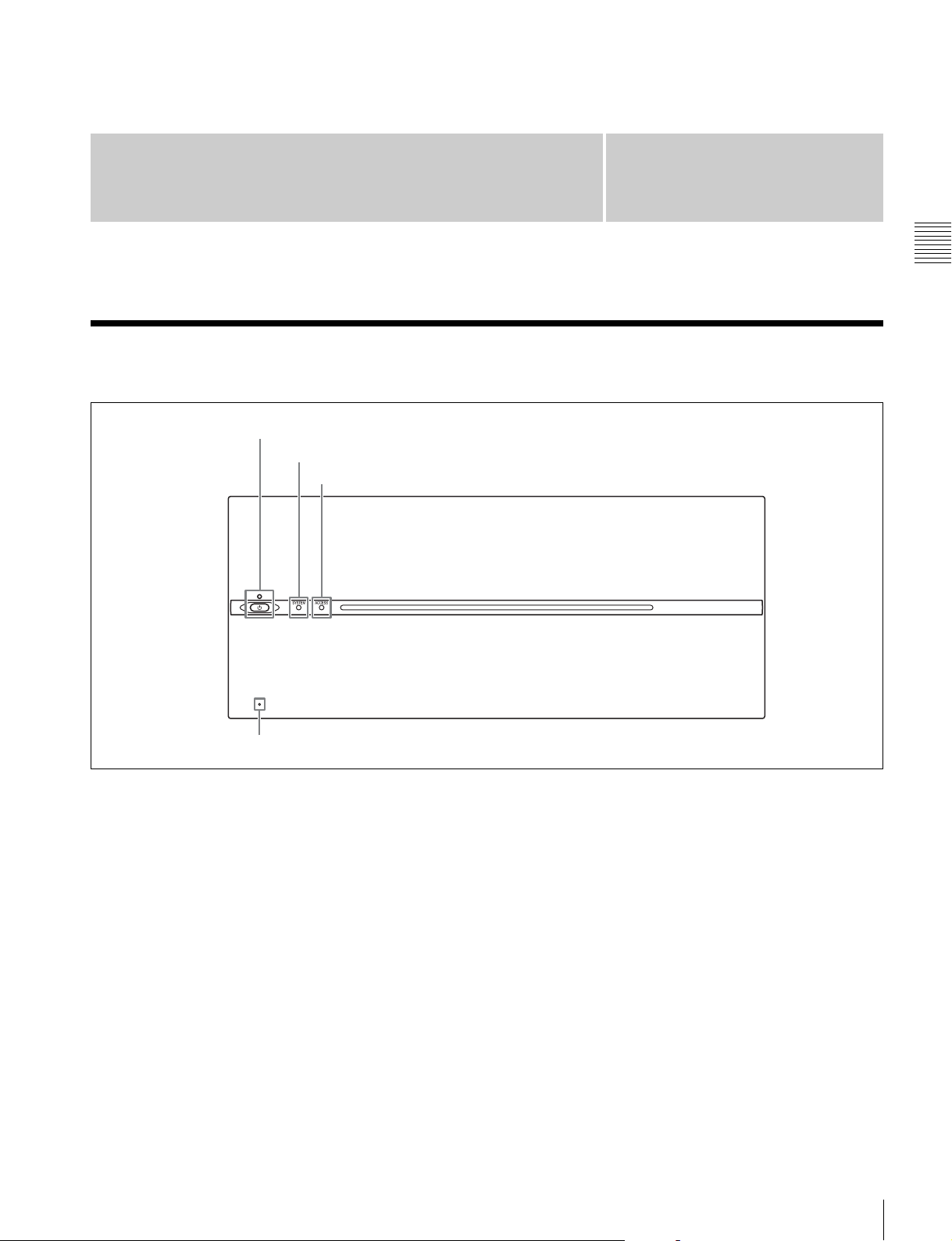
Front Panel
1 On/Standby button and indicator
2 SYSTEM indicator
3 ACCESS indicator
Chapter
2
Chapter 2 Names and Functions of Parts
4 Network reset switch
a On/Standby button and indicator
Switches the unit on/off (standby state). Connecting the
power cord places the unit in standby state, and the
indicator turns on red. Pressing the On/Standby button
while in standby state turns on the unit and the indicator
turns on green. Pressing and holding the On/Standby
button for two seconds switches the unit to standby state,
and the indicator changes to red. To turn the unit on again
after switching from On state to standby state, when the
indicator is red, press and hold the On/Standby switch for
three seconds or longer. The indicator goes out when the
power cord is disconnected.
b SYSTEM indicator
Displays the status of the unit.
Green: Operating normally
Green (flashing once per second): Starting up
Orange (flashing once per second): Warning message
was issued.
Red (high-speed flashing four times per second):
Serious error has occurred.
Purple (flashing once per second): Network reset is in
progress.
c ACCESS indicator
Displays the access status of storage.
Off: Not being accessed
Blue: Accessing
Blue (flashing): Formatting or deleting files
d Network reset switch
Resets the IP address and network settings to their default
values. Insert and hold the end of a paper clip or other thin
object into the hole to operate the internal switch and then
start the unit. The SYSTEM indicator will begin flashing
purple.
Front Panel
5
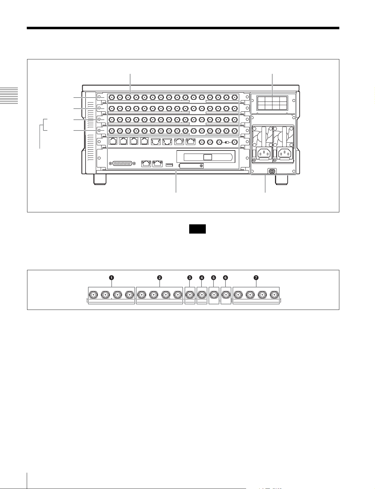
Connector Panel
AInput/output ports (see page 6)
Port A
Chapter 2 Names and Functions of Parts
Port B
Port C
Port D
PWSK-4504
(Option)
A Input/output ports
The unit is equipped with two ports (A, B) as standard, and
up to four ports are supported. Each port has the following
16 connectors. The ports can be configured as inputs or
outputs using the web menu.
PWSK-4506F (Option)
BRemote input/output
section (see page 7)
Note
CPower supply section
(see page 8)
The input/output signal on the SDI IN/OUT connectors
varies with the port setting (input or output) and the SDI
signal format. For details, see “SDI Connector Input/
Output Specifications” (page 43).
1234
56789
HD SDI
IN/OUT
For input ports
a SDI IN/OUT 1 to 4 connectors
Inputs HD SDI signals (up to four cables).
b SDI IN/OUT 5 to 8 connectors
Outputs the same signals input as connectors SDI IN/OUT
1 to 4 for monitors (up to four cables).
c SDI IN/OUT 9 connector
Outputs an HD SDI signal with superimposed text
information and audio meter for a monitor. To
superimpose text information, set [Character On/Off] and
[Character & Audio Meter on SDI-9 Monitor] to “On” on
the [Port] screen of the web menu. The output signal
format can be set to Interlace, Progressive, or PsF in [Port
Configuration] on the [Port] screen of the web menu.
10 IN OUT 1/2 3/4 5/6 7/8
MONITOR
TIME CODE AUDIO (AES/EBU)
IN/OUT
When the playback file format is 4K/QFHD, the output is
down-converted to HD.
Also, you can use this connector as an HD standard-speed
signal input connector during HD high frame rate
recording.
d SDI IN/OUT 10 connector
Outputs the same signal output as the SDI IN/OUT 9
connector. To superimpose text information, set
[Character On/Off] to “On” on the [Port] screen of the web
menu. When “HD Multi-Input” (dual-system input) is
configured in the port settings, the x-1 (main port) monitor
signal is output from the SDI IN/OUT 9 connector and the
x-2 (sub port) monitor signal is output from the SDI IN/
OUT 10 connector.
e TIME CODE IN connector
Inputs a time code generated by an external device.
6
Connector Panel
f TIME CODE OUT connector
When the time code generator is synchronized to the
external time code signal input on the TIME CODE IN
connector, the external time code is output according to the
[TC OUT] setting on the [Port] screen of the web menu.
g AUDIO (AES/EBU) connector
Inputs the audio signals in AES/EBU format for channels
1 to 8.
For output ports
a SDI IN/OUT 1 to 4 connectors
Outputs HD SDI signals (up to four cables).
When [Output Port SDI-1,2,3,4] is set to [Off] on the
[Setup] tab of the [System] screen in the web menu, no
signal is output.
d SDI IN/OUT 10 connector
Outputs an HD SDI signal with superimposed text
information and audio meter for a monitor. To
superimpose text information, set [Character On/Off] to
“On” on the [Port] screen of the web menu. You can also
choose not to output superimposed text information on the
SDI-9 connector by setting [Character & Audio Meter on
SDI-9 Monitor] to “Off” on the [Port] screen. The output
signal format can be set to Interlace, Progressive, or PsF in
[Port Configuration] on the [Port] screen of the web menu.
When the playback file format is 4K, the output is downconverted to HD.
When “HD Multi-Output” (dual-system output) is selected
in the port settings, the x-1 (main port) monitor signal is
output from the SDI IN/OUT 9 connector and the x-2 (sub
port) monitor signal is output from the SDI IN/OUT 10
connector.
Chapter 2 Names and Functions of Parts
b SDI IN/OUT 5 to 8 connectors
Outputs the same signals as connectors SDI IN/OUT 1 to
4 (up to four cables).
c SDI IN/OUT 9 connector
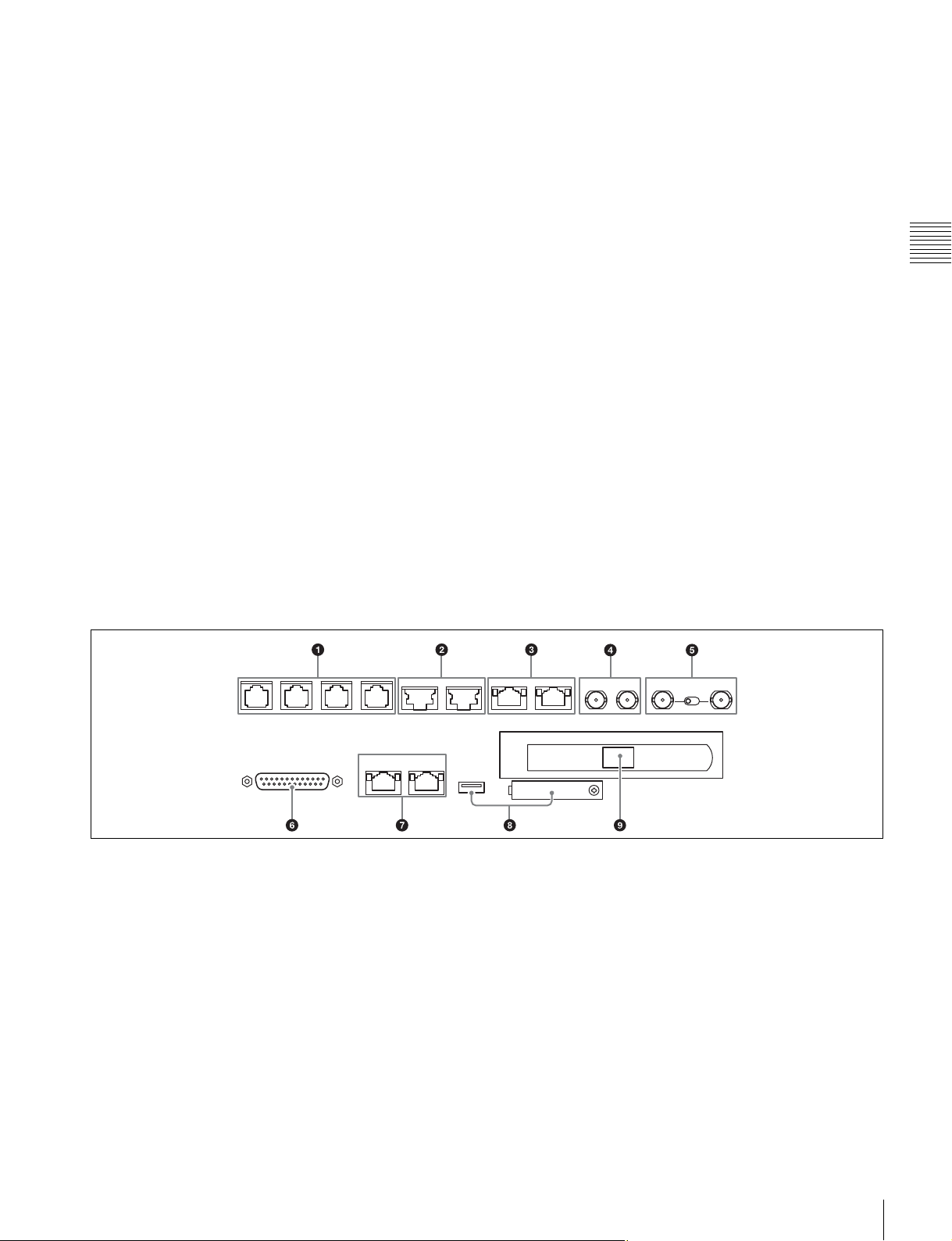
B Remote input/output section
e TIME CODE IN connector
Not used.
f TIME CODE OUT connector
Outputs the playback time code.
g AUDIO (AES/EBU) connector
Outputs the audio signals in AES/EBU format for channels
1 to 8.
a REMOTE 1/2 to 7/8 connectors
Connects to an external device used to control the unit.
Connect devices using a 9-pin remote control cable and a
dedicated RJ45 to D-Sub adaptor cable.
SONY VTR/Disk protocol, VDCP, and Odetics control
protocols are supported.
b SHARE PLAY 1 to 2 connectors
Connects to another PWS-4500 via a network switch to
share material between multiple PWS-4500 units.
c NMI MONITOR 1 to 2 connectors
Outputs four port A to D, HD monitor signals using a
network media interface.
d MONITOR 1 to 2 connectors
Port A to H signals output in multi-monitor HD SDI signal
format via SDI cable connection.
e REF. INPUT connector and 75 Ω termination
switch
Inputs the reference video signal of the selected field
frequency. Input an HD tri-level SYNC signal or SD black
burst signal.
A bridge connection is also supported. Set the 75 Ω
termination switch to OFF if using a bridge connection, or
set it to ON if not using a bridge connection. Use a 5C-FB
cable for the connection.
Connector Panel
7
f GPIO (25-pin) connector
Parallel I/O connector.
For details, refer to the Service Manual or Interface
Manual.
g NETWORK 1 to 2 connectors
Connects to a network cable for monitoring the unit by
SNMP, configuring or checking the unit via HTTP,
transferring files via FTP, etc.
Chapter 2 Names and Functions of Parts
Notes
• For safety, do not connect the connector for peripheral
device wiring that might have excessive voltage to this
port.
Follow the instructions for this port.
• When connecting a network cable, use a shielded-type
cable to prevent malfunction due to radiation noise.
h MAINTENANCE connector
For use by service personnel. Not used for normal
operation.
i NETWORK 3 connector
The unit is equipped with a 10G Ethernet interface board.
Install an SFP+ module and connect to this port using a
network cable.
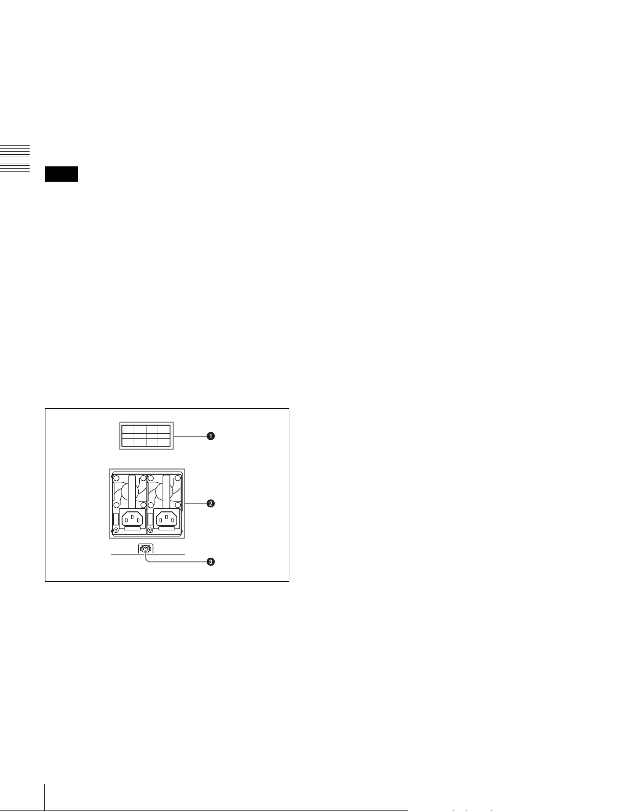
allows the unit to continue operation if one of the supplies
fails.
c U Ground terminal
Connect to ground as required.
C Power supply section
a Option slot
Use as one of the following connectors by installing an
option board.
• NMI LAN connector (when PWSK-4506F is installed)
Transfers audio/video stream over an NMI.
• 6G/12G-SDI connector (when PWSK-4508 is installed)
Transfers audio/video stream over 6G-SDI or 12G-SDI.
b AC power supply unit
Connects to an AC power outlet using the power cord.
The unit can be equipped with two power supply units to
provide power supply redundancy. When used in systems
where reliability is required, a second power supply unit
8
Connector Panel
Setup
Chapter
3
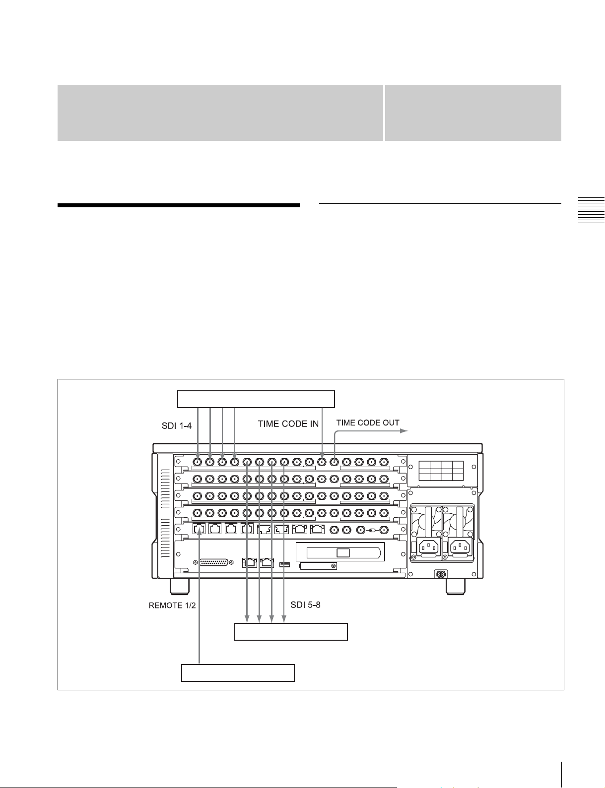
Connecting External Devices
This section describes how to connect the unit to external
devices to record or play back data. This section describes
the configuration with ports A and C used for inputs and
ports B and D used for outputs.
4K digital player
Using the unit as a recorder
The following shows an example of connecting a 4K
digital player or other devices to the input ports and using
the unit as a recorder.
Using a common time code
On this unit, a common time code can be used for multiple
input ports.
To use a common time code, set the master time code in
Master TC (page 20) on the Setup tab of the web menu,
then set “Master TC” in TCG Source (page 30) for each
input port on the Port screen.
Chapter 3 Setup
Video monitor
Remote controller
Connecting External Devices
9
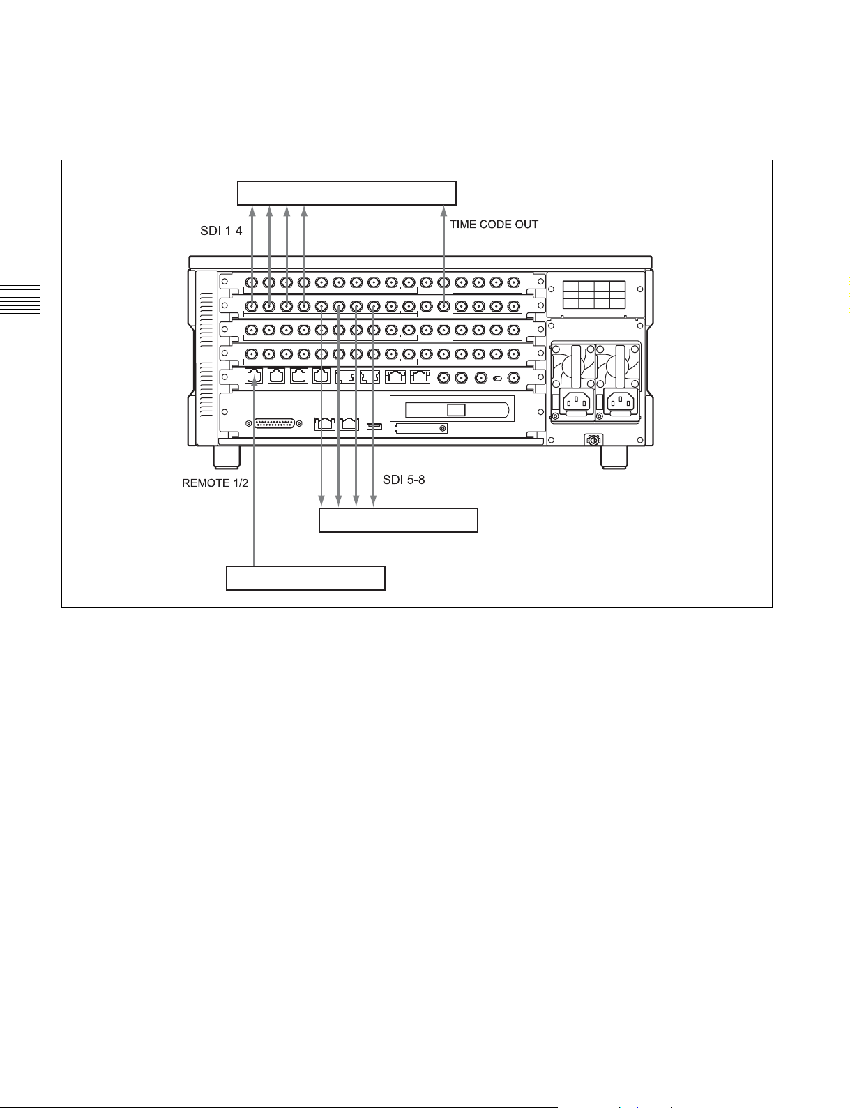
Using the unit as a player
The following shows an example of connecting a 4K
digital recorder or other devices to the output ports and
using the unit as a player.
4K digital recorder
Chapter 3 Setup
Remote controller
Video monitor
10
Connecting External Devices

Displaying the Web Menu
Configuring the Network
You set up and control the unit by connecting to a
computer via the network and displaying the web menu in
a web browser on the computer.
Validated operating environments
Web browser:
• Windows: Microsoft Edge, Internet Explorer 11, Google
Chrome 67, Firefox 60, Opera 53
• Mac: Safari 6
Display: Screen width of 1024 pixels or greater
Connect a computer that satisfies the above requirements
to NETWORK connector 1 or 2 on the rear panel of the
unit. Enter “http://(device_IP_address)/” in the address bar
of a web browser on the computer to display the web
menu. When prompted to provide a user name, enter
“usr1” and click the [Log on] button. The following IP
addresses are configured at the factory for the NETWORK
connectors of the unit.
• NETWORK 1 connector: 192.168.0.1
• NETWORK 2 connector: 192.168.0.2
If the IP addresses are changed, specify the new addresses.
The IP address to connect to can be specified on the
[System] screen > [Network] tab of the web menu.
Access the [System] screen > [Network] tab of the web
menu to configure settings related to the IP address and
network. For details about settings, see “Network tab”
(page 25).
Configure each setting on the [Network] tab, and then click
the [Submit] button. A confirmation message appears.
Click [OK] to restart the unit. The settings are enabled
after the unit restarts.
To display the web menu subsequently, enter the IP
address you specified.
Accessing over a network
When accessing files using a network cable, you can also
transfer files while recording or playback is in progress.
However, since SDI input/output has priority, the transfer
rate over the network may decrease depending on input/
output port usage.
Chapter 3 Setup
Notes
• For details about network settings, contact your network
administrator.
• You may be unable to connect to the network, depending
on your proxy server settings.
• It may not be possible to set the appropriate setting due
to conflicts if the computer is using a multi-session
connection. If this occurs, reconfigure the settings.
• The web menu cannot be displayed on a computer
connected to the NETWORK 3 connector. To display
the web menu, always connect the computer to
NETWORK connector 1 or 2.
Do not browse any other website in the Web browser while
making settings or after making settings. Since the login
status remains in the Web browser, close the Web browser
when you complete the settings to prevent unauthorized
third parties from using the unit or harmful programs from
running.
Displaying the Web Menu / Configuring the Network
11

Setting the System and Boards
You set the system frequency and board settings for the
unit using the web menu. The settings are specified using
a setup wizard.
1
Display the [System] screen of the web menu, and
click the [Board] tab.
2
Click the [Setting] button.
Chapter 3 Setup
The [Step 1] screen appears.
• Input (single-system input)
• HD Multi-Input (dual-system input)
• Input with 2 Boards (using two boards)
• Output (single-system output)
• HD Multi-Output (dual-system output)
• HD Cut Out (for 4K/QFHD video HD cutout)
For high frame rate recording (HD 300i/359i/400i/
479i/300p/359p/400p/479p, 4K 100p/119p), two
boards are used.
No audio signal is recorded if high frame rate
recording is selected.
Click the [Next] button to display the [Step 3] screen.
5
Select the video codec of each port, and click the
[Next] button.
3
Select the system frequency, input/output mode, and
the number of input/output boards installed, then click
the [Next] button.
System frequency
• 23.98 Hz
•24 Hz
•25 Hz
• 29.97 Hz
Input/output mode
• SDI Mode
• NMI Mode
Number of input/output boards
•2 Boards
•4 Boards
Notes
• The input/output mode sets whether the NMI or SDI
signal input/output is used as a reference for the
whole unit. The input/output mode cannot be set
independently for each port.
• When the input/output mode is set to “SDI,” signals
output from NMI lag by one frame. When the input/
output mode is set to “NMI,” signals output from
SDI lead by one frame. In either case, the phase of
the audio signal and TC signal are offset.
• Input signals can use either SDI or NMI only.
• When the input/output mode is set to “NMI” and the
video signal format is QFHD (3840:2160), 1× or 2×
speed recording can be selected. When the video
signal format is HD (1920:1080), only 1× speed
recording can be selected. HD (1280:720) video
signal format cannot be selected.
The [Step 4] screen appears.
6
Select the video signal format of each port, and click
the [Next] button.
For each port, select the video signal format group
from the matrix.
The [Step 5] screen appears.
7
Select the port grouping to operate in sync, and click
the [Next] button.
The [Step 6] screen appears, displaying the selections
made on the [Step 1] to [Step 5] screens.
8
Check the selected items, and click the [Submit]
button. A confirmation message appears. Click [OK].
The unit restarts automatically and the settings are
enabled.
To set each port individually, see “Port Screen” (page 29)
of the web menu.
Note
Changing the system frequency or other board settings will
disable the loop recording area settings. Reconfigure the
settings on the [Loop] tab on the [Storage] screen of the
web menu, as required.
Click the [Next] button to display the [Step 2] screen.
4
Select the input/output type of each port, and click the
[Next] button.
12
Setting the System and Boards

Maximum Recording Time of Memory
The following is a guide to the maximum recording time
when recording to internal memory.
Format 2 TB 4 TB 6 TB 8 TB
XAVC
Class480
XAVC
Class300
XAVC
Class100
Avid DNxHD 45HD 25p 55.6 111.3 166.9 222.5
Avid DNxHD
145
Avid DNxHD
220x
Apple
ProRes 422
LT
Apple
ProRes 422
Apple
ProRes 422
HQ
4K 23.98p 9.7 19.5 29.3 39
4K 29.97p 7.8 15.6 23.4 31.2
4K 50p 4.8 9.6 14.4 19.2
4K 59.94p 4 8 12 16
4K 23.98p 14.8 29.7 44.6 59.4
4K 29.97p 11.8 23.7 35.6 47.5
4K 50p 7.3 14.7 22.1 29.5
4K 59.94p 6.1 12.3 18.4 24.6
HD 50i 27.5 55.1 82.7 110.3
HD 59.94i 27.6 55.2 82.9 110.5
HD 50p 14.9 29.9 44.9 59.9
HD 59.94p 15.2 30.5 45.8 61.1
HD 29.97p 46.3 92.7 139.1 185.5
HD 50i 27.5 55.1 82.7 110.3
HD 59.94i 22.9 45.9 68.9 91.9
HD 50p 14.9 29.9 44.9 59.9
HD 59.94p 12.4 24.9 37.4 49.9
HD 50i 19.4 38.8 58.2 77.7
HD 59.94i 16.1 32.3 48.5 64.7
HD 50p 10.2 20.5 30.8 41.1
HD 59.94p 8.5 17.1 25.7 34.3
HD 50i 33.1 66.3 99.5 132.6
HD 59i 27.6 55.2 82.9 110.5
HD 50p 18.3 36.6 55.0 73.3
HD 59p 15.2 30.5 45.8 61.1
HD 50i 23.6 47.2 70.8 94.5
HD 59.94i 19.6 39.3 59 78.7
HD 50p 12.6 25.3 38 50.7
HD 59.94p 10.5 21.1 31.6 42.2
HD 50i 17.3 34.7 52.1 69.5
HD 59.94i 14.4 28.9 43.4 57.9
HD 50p 9.1 18.2 27.4 36.5
HD 59.94p 7.6 15.2 22.8 30.4
Unit: Hours (approx.)
Chapter 3 Setup
The maximum recording time varies depending on the
recording format.
Maximum Recording Time of Memory
13
Web Menu
Chapter
4
The web menu comprises the following screens.
Home screen: Displays the operating status of unit’s
boards and the network.
Status screen: Displays a list of errors and warnings that
have occurred on the unit.
System screen: Makes basic settings for the unit.
Port screen: Makes settings for each port of the unit.
Chapter 4 Web Menu
File screen: Displays a file list.
Storage screen: Displays information about memory and
configures the memory of the unit.
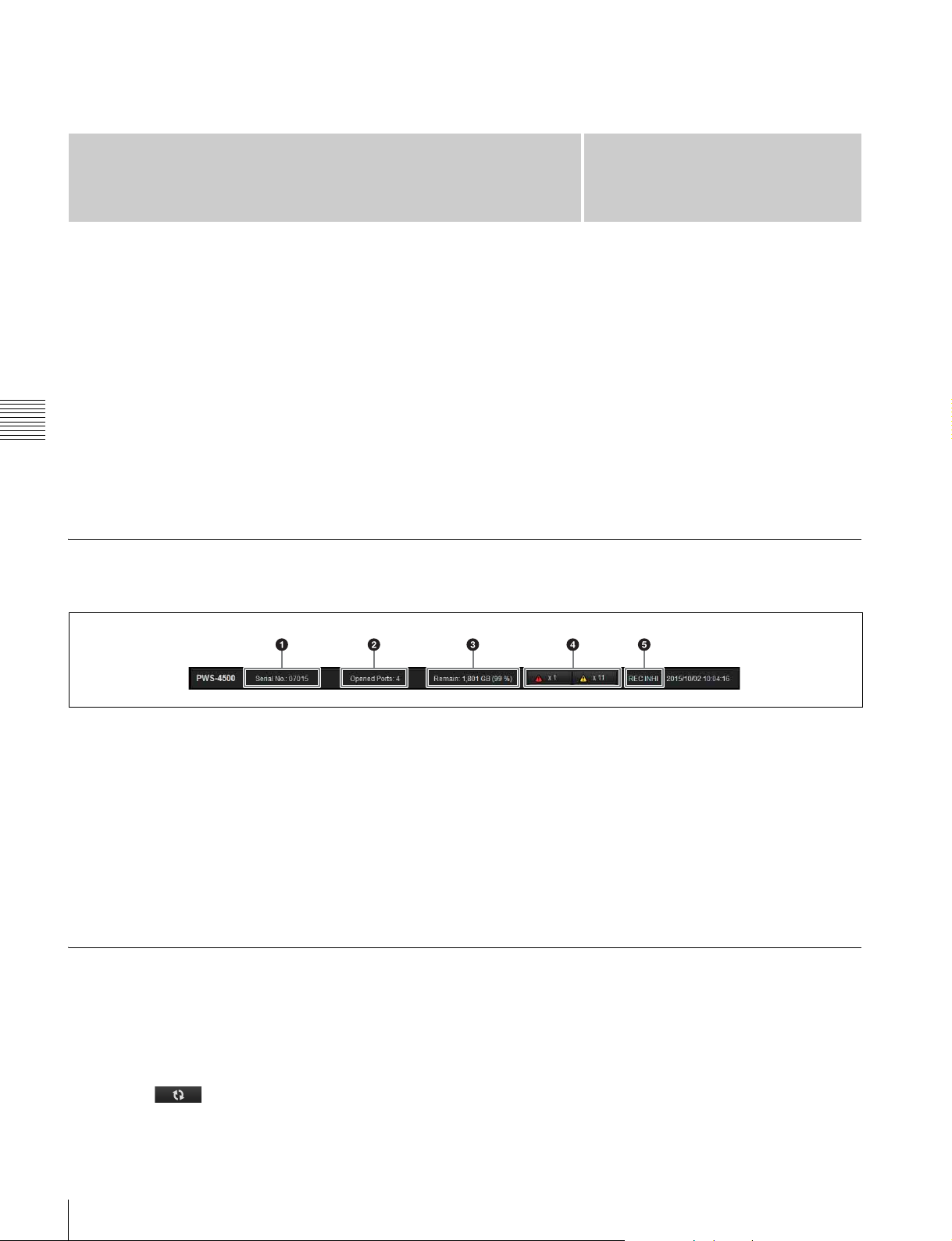
Title Bar
The title bar is common to each screen of the web menu.
a Serial number
Displays the serial number of the unit.
Maintenance screen: Used for maintenance of the unit.
For details about this screen, refer to the Service
Manual.
SNMP screen: Makes SNMP settings. For details about
this screen, refer to the Service Manual.
In the descriptions of each screen, the underlined option is
the default value for each item.
Clicking the indicator displays detailed information about
the error/warning.
b Number of open ports
c Storage capacity
d Error/warning indicators
Displays the number of errors and warnings that have
occurred.
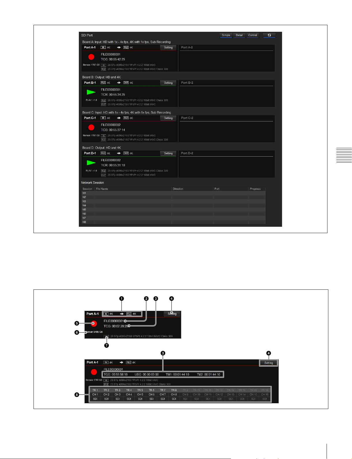
Home Screen
Displays the operating status of units boards and the
network.
The Home screen supports simple display mode and detail
display mode. You can switch mode using the [Simple]/
[Detail] buttons.
Clicking the button, turning it on, updates the
screen display automatically.
14
e REC INHI indicator
Indicates when recording is inhibited (red).
The indicator is white when recording is supported.
The [Control] button function is provided for service
administrators. A password is required to use it.
Chapter 4 Web Menu
HD-SDI Port
Displays the status of each port.
For inputs
The following information is displayed.
Simple display
Detailed display
The port settings vary depending on whether the port is
used for input or for output.
15
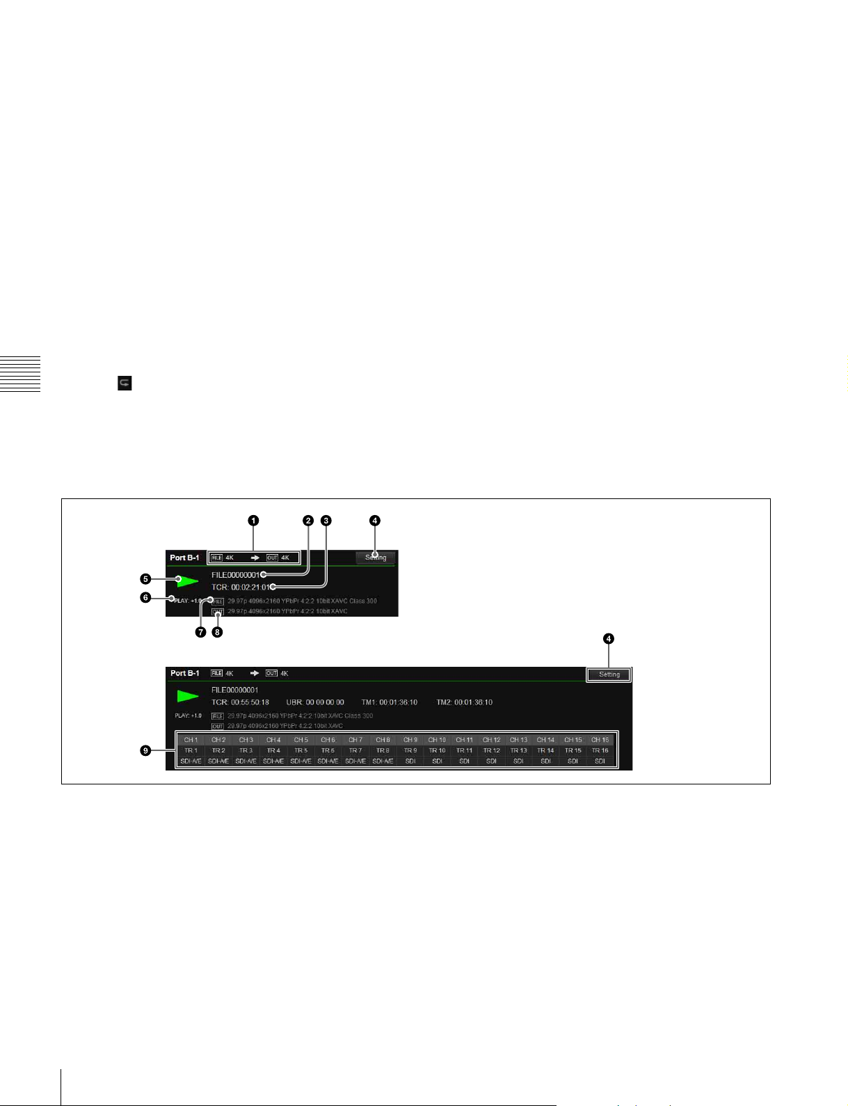
a Input/recording format
[IN] displays the video format (HD/QFHD/4K) of the input
signal, and [FILE] displays the video format of the recording.
b File name
Displays the name of the file being recorded. “File:
NEXT” is displayed before recording.
c Time code display
Displays time code data (TCG).
In detail display mode, UBG, TM1, and TM2 are also
displayed simultaneously.
d [Setting] button
Displays the [Port] screen (page 29) for the corresponding
port to configure port settings.
e Recording indicator
Displays z mark when recording.
Displays icon when a loop recording area is specified.
Chapter 4 Web Menu
For outputs
The following information is displayed.
f Remaining capacity
Displays the remaining memory capacity.
When a loop recording area is specified, this displays the
capacity of the writable area of the capacity assigned to the
loop recording area. In loop recording, the recording loops
back to the start of the loop recording area when it reaches
the end of the area, overwriting the previous recording.
However, if a subclip is created in a loop recording area
file, the subclip area cannot be overwritten. Accordingly,
the capacity of the loop recording area decreases by the
size of the subclip.
If the remaining capacity that can be used for loop
recording is reduced to less than five minutes after creating
a subclip in the loop recording area, further subclips cannot
be created.
g [IN]
Displays the video format of the input signal.
h Audio track (detail display mode only)
Displays the signal (SDI, NMI, or AES/EBU) used for
each audio track.
Simple display
Detailed display
a File/output format
[FILE] displays the video format (HD/QFHD/4K) of the
file, and [OUT] displays the video format of the output
signal.
b File name
Displays the name of the file being played back. “Sub” is
displayed beside the file name when playing back a
subclip.
c Time code display
Displays time code data (TCR).
In detail display mode, UBR, TM1, and TM2 are also
displayed simultaneously.
d [Setting] button
Displays the [Port] screen (page 29) for the corresponding
port to configure port settings.
16

e Playback indicator
Displays “B” during playback. The following are
displayed as the playback mode.
• No indication: Normal file playback
• (File Repeat): File repeat playback
• (List): Normal playlist playback
• (List Repeat): Playlist repeat playback
f Playback status indicator
The following are displayed as the playback status.
•CLOSE
•STOP
• PLAY (playback speed)
• SHUTTLE (playback speed)
• JOG (FWD/REV)
• VAR (playback speed)
•STILL
g [FILE]
Displays the video format of the file being played back.
h [OUT]
Displays the video format of the video signal being output.
i Audio track (detail display mode only)
Displays which external channel is used for each audio
track, and the signal (SDI, NMI, or AES/EBU) used.
Chapter 4 Web Menu
Network Session
Displays the operating status of the network connection.
The following information is displayed.
Session
Displays the session name (N1 to N8).
File Name
Displays the name of the file being transferred.
Direction
Displays the transfer direction as an icon (unit t computer,
unit T computer).
Port
Displays the transfer speed (1G/10G) of the network.
Progress
Displays the transfer progress.
Abort
Clicking the button displayed for each session forcibly
terminates network transfer.
17
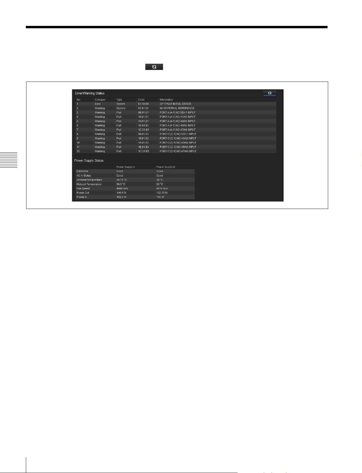
Status Screen
Displays a list of errors and warnings that have occurred on
the unit, and the power supply status. Click the
button, turning it on, to update the display automatically.
Chapter 4 Web Menu
Error/Warning Status
Displays a list of errors and warnings.
Power Supply Status
Displays the status of the AC power supply unit(s).
Existence
Indicates whether the AC power supply unit(s) have been
recognized.
AC In Status
Indicates the presence or otherwise of AC input.
Ambient Temperature
Displays the ambient temperature of the unit.
Hotspot Temperature
Displays the hotspot temperature.
Fan Speed
Displays the speed of the fan.
Power Out
Displays the output power.
Power In
Displays the input power.
18
Status Screen
System Screen
Makes basic settings for the unit.
Board tab
Makes input/output board settings using a setup wizard.
Click the [Setting] button at the bottom of the screen to
start configuration.
For details about settings, see “Setting the System and
Boards” (page 12).
Step 1
Sets the system frequency, input/output mode, and the
number of input/output boards for the unit.
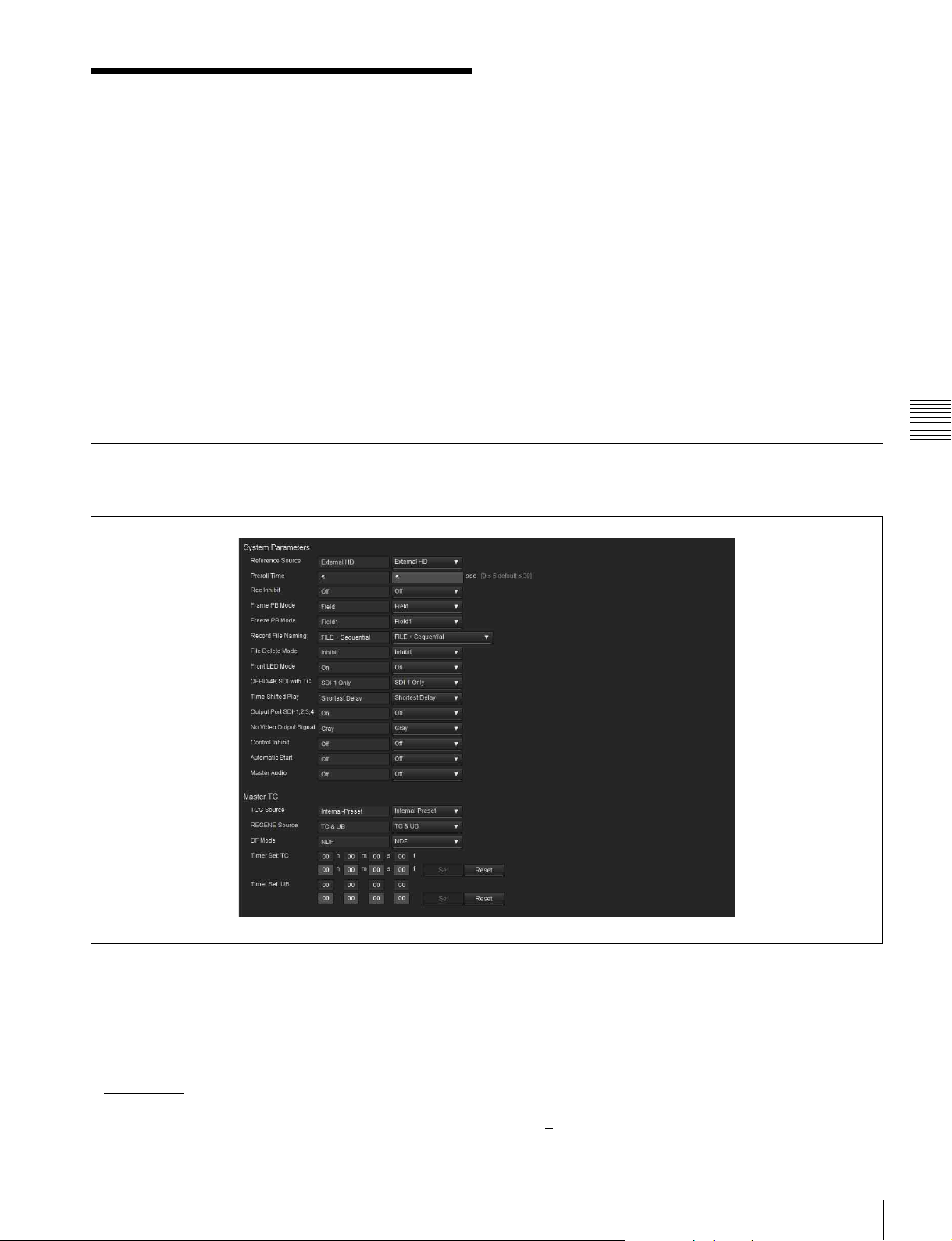
Setup tab
Makes basic operating mode settings of the unit.
Step 2
Sets the input/output type of ports A to D.
Step 3
Sets the video codec of each port.
Select the codec using the radio buttons.
Step 4
Sets the video signal format of each port.
Select the format to use from the matrix.
Step 5
Select the port grouping to operate in sync.
You can set up multiple combinations of input ports or
output ports.
Step 6
Check the settings made in steps 1 to 5, and submit the
settings.
Chapter 4 Web Menu
System Parameters
Reference Source
Selects the reference signal for operation of the unit. In
NMI mode, only “External HD” and “External SD” can be
selected.
• External HD: Tri-level SYNC signal input on the REF.
INPUT connector
• External SD: SD signal input on the REF. INPUT
connector
• Input Board A-1, Input Board A-2 to Input Board D-1,
Input Board D-2: Signal input to the HD SDI INPUT
signal on the corresponding board
Preroll Time
Sets the preroll time in units of seconds.
•0 to 5
to 30 seconds
System Screen
19
 Loading...