

Sony PWS-110RX1 Installation Manual

NETWORK RX STATION
PWS-110RX1
OPTIONAL POWER SUPPLY
PWSK-101
INSTALLATION MANUAL
1st Edition
Serial No. 120001 and Higher: PWS-110RX1 (SY)

!警告
このマニュアルは,サービス専用です。
お客様が,このマニュアルに記載された設置や保守,点検,修理などを行うと感電や火災,
人身事故につながることがあります。
危険をさけるため,サービストレーニングを受けた技術者のみご使用ください。
! WARNING
This manual is intended for qualified service personnel only.
To reduce the risk of electric shock, fire or injury, do not perform any servicing other than that
contained in the operating instructions unless you are qualified to do so. Refer all servicing to
qualified service personnel.
! WARNUNG
Die Anleitung ist nur für qualifiziertes Fachpersonal bestimmt.
Alle Wartungsarbeiten dürfen nur von qualifiziertem Fachpersonal ausgeführt werden. Um die
Gefahr eines elektrischen Schlages, Feuergefahr und Verletzungen zu vermeiden, sind bei
Wartungsarbeiten strikt die Angaben in der Anleitung zu befolgen. Andere als die angegeben
Wartungsarbeiten dürfen nur von Personen ausgeführt werden, die eine spezielle Befähigung
dazu besitzen.
! AVERTISSEMENT
Ce manual est destiné uniquement aux personnes compétentes en charge de l’entretien. Afin
de réduire les risques de décharge électrique, d’incendie ou de blessure n’effectuer que les
réparations indiquées dans le mode d’emploi à moins d’être qualifié pour en effectuer d’autres.
Pour toute réparation faire appel à une personne compétente uniquement.
:REMOTE1/2コネクター
:REMOTE3/4コネクター
:REMOTE5コネクター
For safety, do not connect the connector for peripheral
device wiring that might have excessive voltage to the
following port(s).
: LAN 1 connector
: LAN 2 connector
: REMOTE 1/2 connector
: REMOTE 3/4 connector
: REMOTE 5 connector
Follow the instructions for the above port(s).
For kundene i Norge
Dette utstyret kan kobles til et IT-strømfordelingssystem.
10
PWS-110RX1

Attention-when the product is installed in Rack:
1. Prevention against overloading of branch circuit
When this product is installed in a rack and is
supplied power from an outlet on the rack, please
make sure that the rack does not overload the supply
circuit.
2. Providing protective earth
When this product is installed in a rack and is
supplied power from an outlet on the rack, please
confirm that the outlet is provided with a suitable
protective earth connection.
3. Internal air ambient temperature of the rack
When this product is installed in a rack, please make
sure that the internal air ambient temperature of the
rack is within the specified limit of this product.
4. Prevention against achieving hazardous
condition due to uneven mechanical loading
When this product is installed in a rack, please
make sure that the rack does not achieve hazardous
condition due to uneven mechanical loading.
設置時には,通気やサービス性を考慮して設置スペース
を確保してください。
. ファンの排気部( リアパネル面,右側面後ろ側,トッ
プパネル後ろ側 )や通気孔(フロントパネル面,左側
面フロント側)をふさがない。
. 通気のために,セット周辺に空間をあける。
. 作業エリアを確保するため,セットの左側面および右
側面は 4cm 以上,セット後方は 40cm 以上の空間を
あける。
机上などの平面に設置する場合は,左側面および右側面
は 4cm 以上の空間をそれぞれ確保してください。ただ
し,セット上部はサービス性を考慮し 40cm 以上の空
間を確保することを推奨します。
When installing, the installation space must be secured
in consideration of the ventilation and service operation.
. Do not block the fan exhaust areas (rear panel and
rear part of the right side panel and rear part of the top
panel) and vents (front panel, front part of the left side
panel) with objects.
. Leave a space around the unit for ventilation.
. Secure working spaces (at least 4 centimeters from
the left panel and right panel and at least 40 centime-
ters from the rear panel of the unit).
When the unit is installed on the desk or the like, leave at
least 4 centimeters of space in the left and right sides.
Leaving 40 centimeters or more of space above the unit
is recommended for service operation.
5. Install the equipment while taking the operating
temperature of the equipment into consideration
For the operating temperature of the equipment, refer
to the specifications of the Operation Manual.
6. When performing the installation, keep the
following space away from walls in order to
obtain proper exhaust and radiation of heat.
Right, Left: 4 cm (1.6 inches) or more
Rear: 10 cm (3.9 inches) or more
PWS-110RX1
1 (P)


Table of Contents
Manual Structure
Purpose of this manual ............................................................ 2 (E)
Related manuals ...................................................................... 2 (E)
Trademarks .............................................................................. 2 (E)
1. Installation
1-1. Installation Procedure ................................................1-1 (E)
1-2. Accessories ................................................................1-1 (E)
1-3. Operating Environment and Installation Space .........1-2 (E)
1-3-1. Operating Environment....................................1-2 (E)
1-3-2. Installation Space .............................................1-3 (E)
1-4. Power Supply ............................................................1-4 (E)
1-4-1. Power Supply Specifications ........................... 1-4 (E)
1-4-2. Recommended Power Cord ............................. 1-4 (E)
1-5. Installing an Optional Power Unit .............................1-5 (E)
1-6. Rack Mounting ..........................................................1-6 (E)
1-6-1. Parts Required ..................................................1-7 (E)
1-6-2. Removing the Front Panel ...............................1-8 (E)
1-6-3. Mounting to Rack (M5 Screw Holes) ..............1-8 (E)
1-6-4. Mounting to Rack (Square Holes) ................... 1-8 (E)
1-6-5. Installing the Front Panel ...............................1-10 (E)
1-7. Connector Input/Output Signals ..............................1-11 (E)
1-8. Connectors and Cables ............................................ 1-12 (E)
2. Service Overview
2-1. Onboard Switches .....................................................2-1 (E)
2-1-1. Settings of Onboard Switch ............................. 2-1 (E)
PWS-110RX1
1 (E)

Purpose of this manual
Related manuals
Manual Structure
This manual is the installation manual of Network RX Station PWS-110RX1.
This manual is intended for use by system engineers and service engineers,
and provides helpful information for installing PWS-110RX1, such as operating
environment, installation space, connection information, initial settings and so on.
Besides this Installation Manual, the following manuals are available for PWS110RX1.
. Operation Manual (Supplied with this unit)
This manual contains information required to operate and use the unit.
. Service Manual (Available on request)
This manual describes service overview, error messages, periodic maintenance and
inspection, replacement of main parts, and so on of the unit to provide information
required for block-level service.
Trademarks
. Installation manual for RMM-10 (Supplied with RMM-10)
This is necessary to install the unit to a 19 inch equipment rack.
Trademarks and registered trademarks described in this manual are as follows.
. The terms HDMI and HDMI High-Definition Multimedia Interface, and the HDMI
Logo are trademarks or registered trademarks of HDMI Licensing LLC in the
United States and other countries.
Other system names and product names written in this manual are usually registered
trademarks or trademarks of respective development manufacturers.
2 (E)
PWS-110RX1
Section 1
Installation
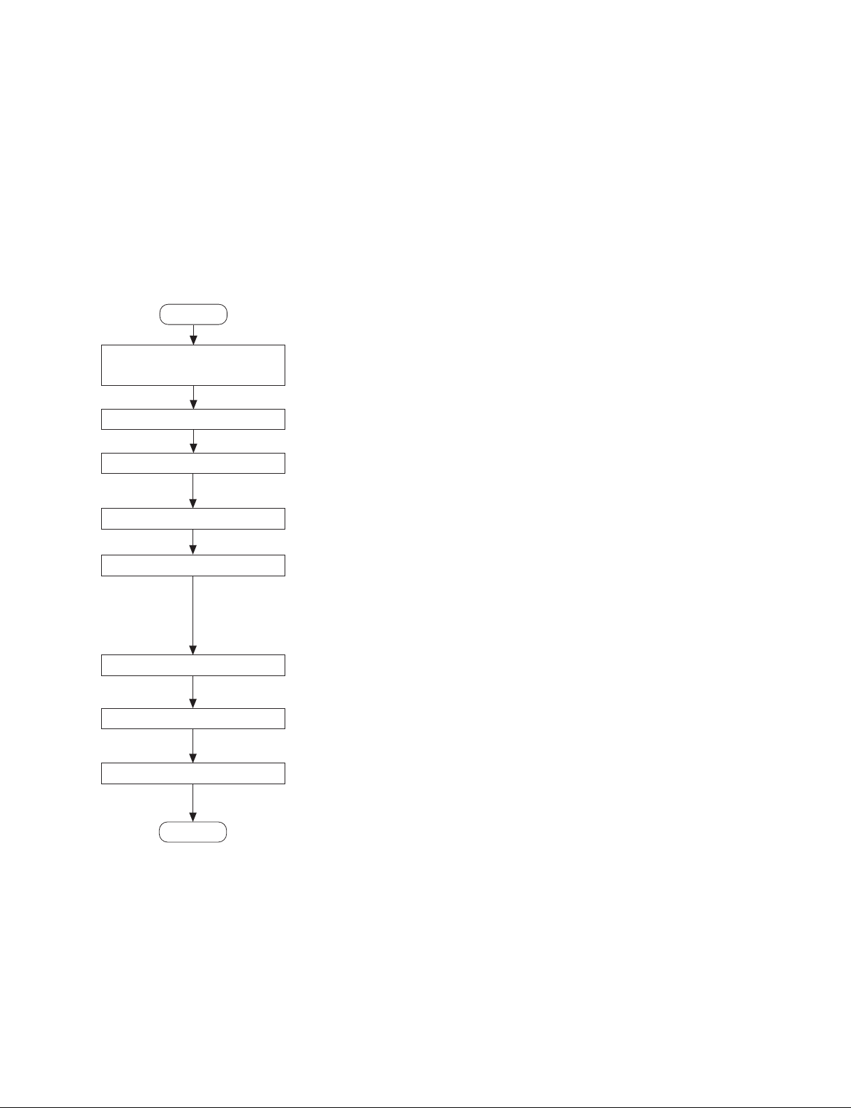
1-1. Installation Procedure
The following flowchart shows the installation procedure
of the unit.
For details of each work, refer to the relevant section.
The Operation Manual is also required for the items
marked with an asterisk (*).
Start
Determination of
installation place
Unpacking
Installing an optional power unit
Removing the front panel
1-3. Operating Environment and Installation Space
1-4. Power Supply
1-5. Installing an Optional Power Unit
(This process is not necessary if you don't install an optional power unit.)
1-6-1. Part Required
1-6-2. Removing the Front Panel
1-2. Accessories
. Operation Manual (1)
. Installation Manual (this manual) (1)
. Operation Guide (1)
. Screws for Rack Mount (4)
Installing the main unit to the rack
Installing the front panel
Connection
Operation check
End
1-6-3. Mounting to Rack (M5 Screw Holes)
Refer to the Installation Manual for RMM-10.
(This process is not necessary if you don't mount this unit into a rack.)
1-6-4. Mounting to Rack (Square Holes)
(This process is not necessary if you don't mount this unit into a rack.)
1-6-5. Installing the Front Panel
1-7. Connector Input/Output Signals
1-8. Connectors and Cables
Check the operation of the unit depending on the configuration of the system.
PWS-110RX1
1-1 (E)
 Loading...