

Sony PWS-110NM1 Operation Manual

Sony Corporation
PWS-110NM1(SYL/CNC)
4-596-992-03(1)
Printed in Japan
2018.08 32
© 2017
IP LIVE SYSTEM MANAGER STATION
PWS-110NM1
電気製品は、安全のための注意事項を守らないと、火災や人
身事故になることがあります。
このオペレーションマニュアルには、事故を防ぐための重要な注意事項と製品
の取り扱いかたを示してあります。このオペレーションマニュアルをよくお読
みのうえ、製品を安全にお使いください。お読みになったあとは、いつでも見
られるところに必ず保管してください。
OPERATION MANUAL
[Japanese/English/French/German/Italian/Spanish/Chinese]
1st Edition (Revised 2)

日本語
目次
概要 .................................................................................................................................. 3
システム構成例 ............................................................................................................................................4
各部の名称と働き ........................................................................................................... 5
前面 ....................................................................................................................................................................... 5
前面(パネルを外した場合)...............................................................................................................5
背面 ....................................................................................................................................................................... 6
準備 .................................................................................................................................. 7
初期設定............................................................................................................................................................. 7
Web メニューの表示................................................................................................................................8
システム設定..................................................................................................................................................8
クライアント PC に証明書をインストールする..................................................................8
ライブラリ等のライセンスについて............................................................................................9
メンテナンスアプリケーションの操作 ..................................................................... 10
使用上のご注意 ............................................................................................................ 10
仕様 ............................................................................................................................... 11
安全のためのご注意が PWS-110 オペレーションガイド(付属)に記載されてい
ますので、ご使用の前にお読みください。
目次
2

概要
本機は、IPLiveSystemManager を使用して、映像信号や
音声信号の経路切り換え制御を行うシステムです。
NetworkedMediaInterface機器(以下、NMI 機器)、また
は Dante プロトコルで動作する IPAudio 機器(以下、
Dante 機器)を、汎用のネットワークスイッチを介して、
Ethernet などの IP ネットワークで接続し、NMI 機器同士
または Dante 機器同士で映像/音声入出力の経路切り換え
を制御します。
本機の機能を次に示します。
NMI 機器同士および Dante 機器同士の映像/音声入出力
信号の経路切り換え制御
汎用のネットワークスイッチを介して IP ネットワークで接
続された NMI 機器同士、または Dante 機器同士の映像/
音声入出力経路の切り換えを行います。
機器の設定管理
IPLiveSystemManager の GUI 画面から、NMI 機器の設
定内容の参照や変更ができます。また、Dante 機器の設定
内容を参照できます。
役割を意識したユーザー管理
ユーザーの役割を、システム管理を意識した
「Administrator」、運用管理を意識した「Manager」、運用
実行を意識した「Operator」の 3 種類に分類し、役割を意
識したユーザー管理ができます。
ユースケースに応じたワークグループ管理
NMI 機器や Dante 機器の映像/音声ストリーミング入出力
用仮想端子やユーザーを、使用する映像や音声の内容に応
じてワークグループでグルーピングし、ユースケースごと
に切り換えながら運用・管理できます。
ネットワークトポロジー監視
汎用のネットワークスイッチを介して互いに接続されてい
る機器のネットワークトポロジー情報を視覚化し、ネット
ワークスイッチのポートに流れるパケットの流量を監視し
たり、パケットロスなどのネットワーク上のエラーを表示
したりすることができます。
JP
WebGUI
本機に搭載されている IPLiveSystemManager の操作や設
定は、クライアント PC の Web ブラウザーに表示される
GUI で実行できます。
概要
3
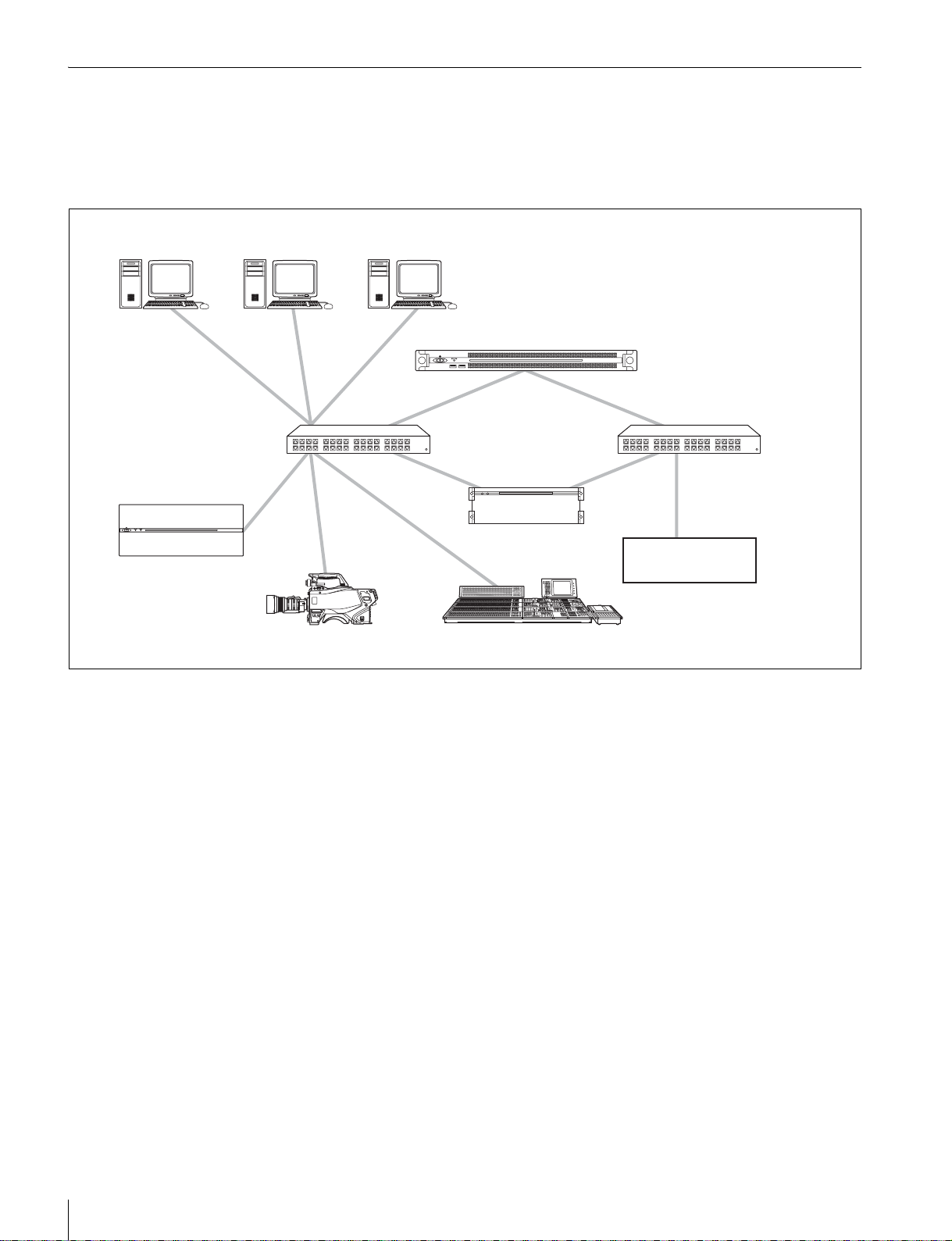
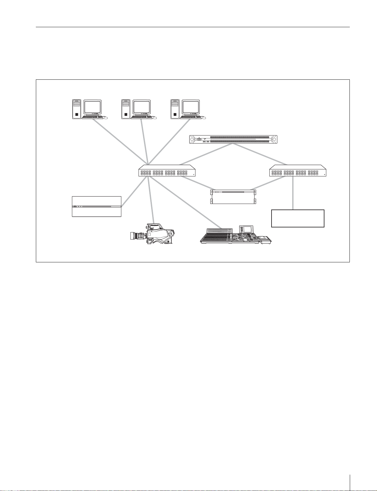
システム構成例
本機の LAN 端子とネットワークスイッチの LAN端子を
イーサネットケーブルで接続します。同様に、NMI 機器お
よび Dante 機器の LAN 端子とネットワークスイッチの
LAN 端子をイーサネットケーブルで接続します。また、ク
Administrator
NMI 機器用
ネットワークスイッチ
(10GbE)
AV サーバー
Manager Operator
ライアント PC をネットワークスイッチと接続し、クライ
アント PC の Web ブラウザーから GUI で PWS-110NM1 の
操作を行います。
PWS-110NM1
Dante 機器用
ネットワークスイッチ
(1GbE)
AudioMux/Demux
ボード
IPAudio 機器
(Dante 対応)
システムカメラ
I/Oスイッチャー
概要
4
各部の名称と働き
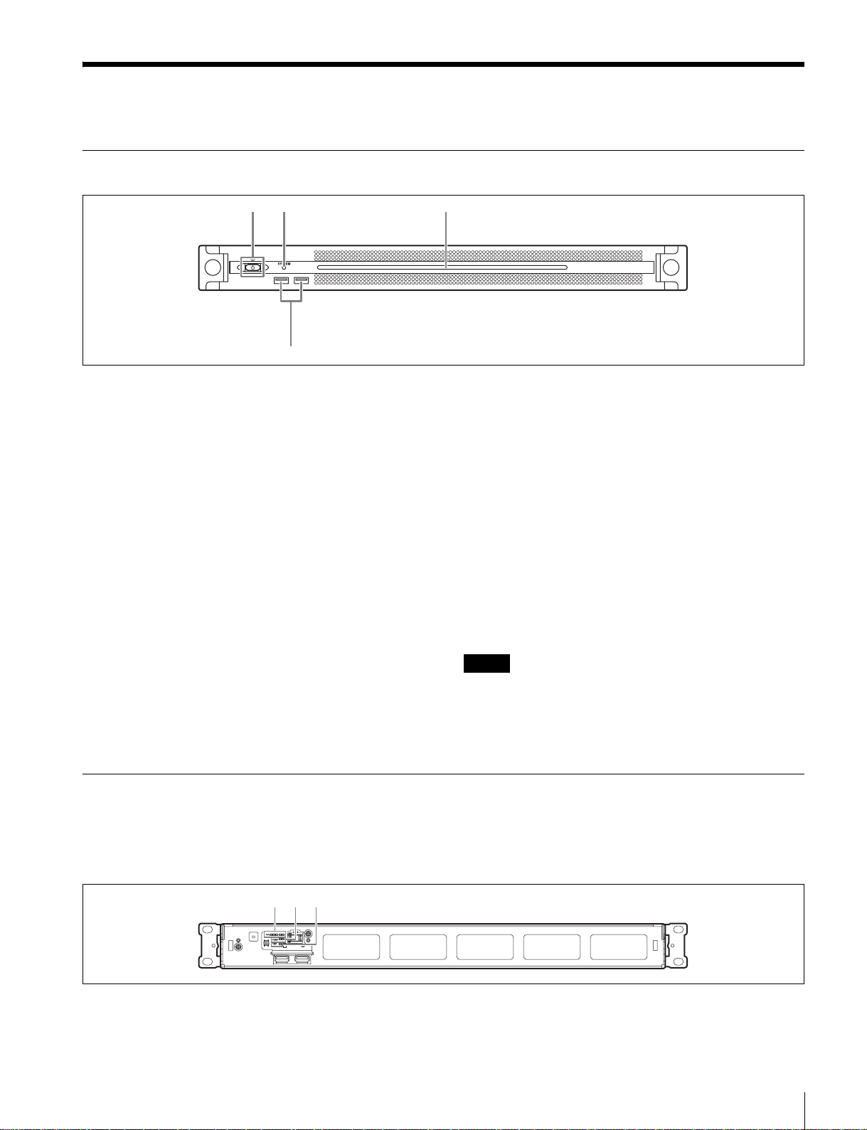
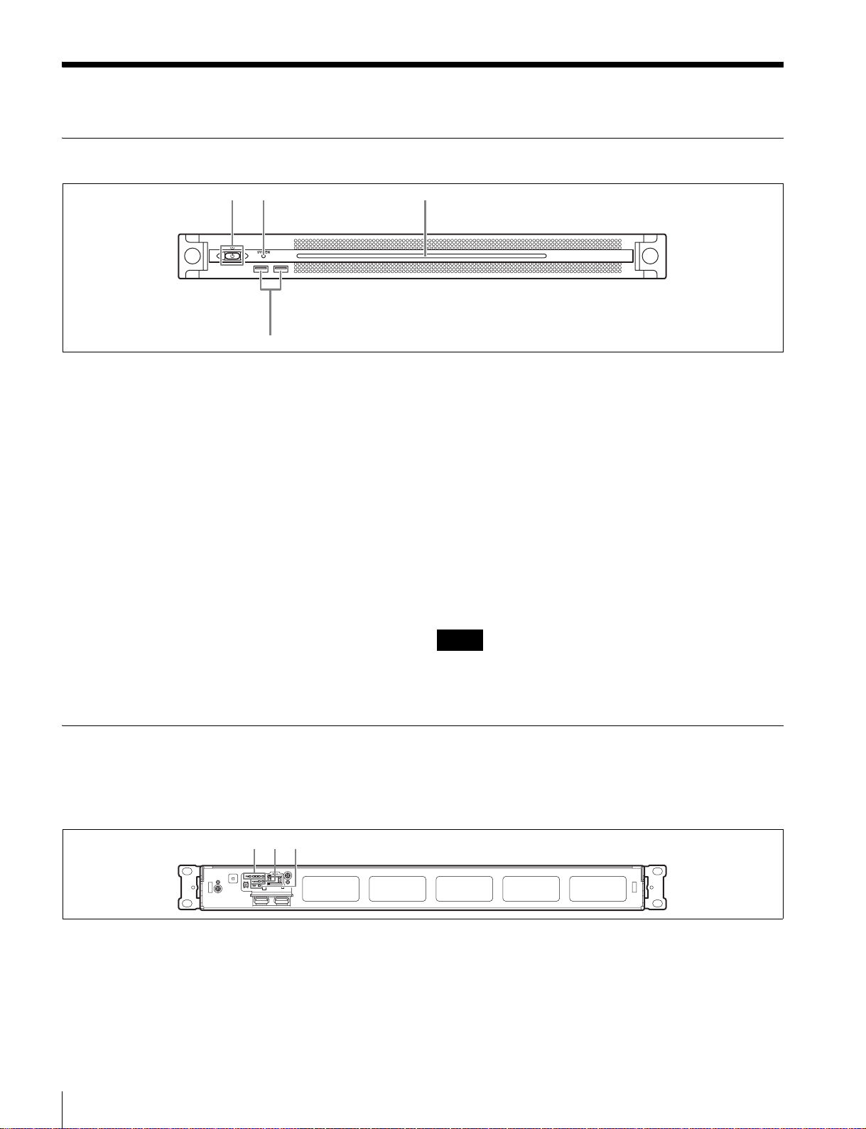
前面
12 3
4
a オン/スタンバイボタンおよびインジケーター
本機のオン /スタンバイを切り換えます。電源コードを接
続するとスタンバイ状態になり、インジケーターが赤色に
点灯します。スタンバイ状態のときにオン /スタンバイボ
タンを押すと、本機が起動してオン状態になり、インジ
ケーターが緑色に点灯します。オン状態のときにオン / ス
タンバイボタンを 2 秒以上長押しすると、スタンバイ状態
への移行を開始し、スタンバイ状態になるとインジケー
ターが赤色に点灯します。オン状態からスタンバイ状態に
した後、再度オンにする場合は、インジケーターが赤色に
点灯した後 3 秒以上たってからボタンを押してください。
電源コードが接続されていないときは、インジケーターが
消灯します。
b SYSTEM インジケーター
本機の状態を示します。
緑色点灯:正常動作中
緑色点滅(1秒周期):システム起動中またはスタンバイ移
行中
前面(パネルを外した場合)
オレンジ色点滅(1秒周期):ワーニング発生
赤色高速点滅(1/4秒周期):エラー発生
c フロントパネル LED
Web メニューでの設定によって、点灯 / 消灯します。設定
は、メンテナンス画面の [Settings] ページ−[001:LINE
LED]で行います。
d USB 端子(前面)
本機の初期設定をする際に、キーボードやマウスを接続で
きます。
本書で説明されていない USB 機器については対応していま
せん。
ご注意
• 前面の USB 端子は、両ポートとも給電に対応しています
(900 mA)。
• ケーブルは、SuperSpeedUSB ケーブルをご使用ください。
SYSTEM インジケーターや Web メニューの表示でエラー
が通知された場合に、パネルを外してハードウェア各部の
ステータスを確認することができます。
123
a FAN インジケーター
ファンのいずれかに障害が発生した場合に、対応するイン
パネルを外すには、前面パネル左右のネジをゆるめ、手前
に引きます。
ジケーターが赤く点灯します。
各部の名称と働き
5
b POWER インジケーター
AC 電源ユニットのどちらかに故障が検出された場合に、
対応するインジケーターが赤く点灯します。
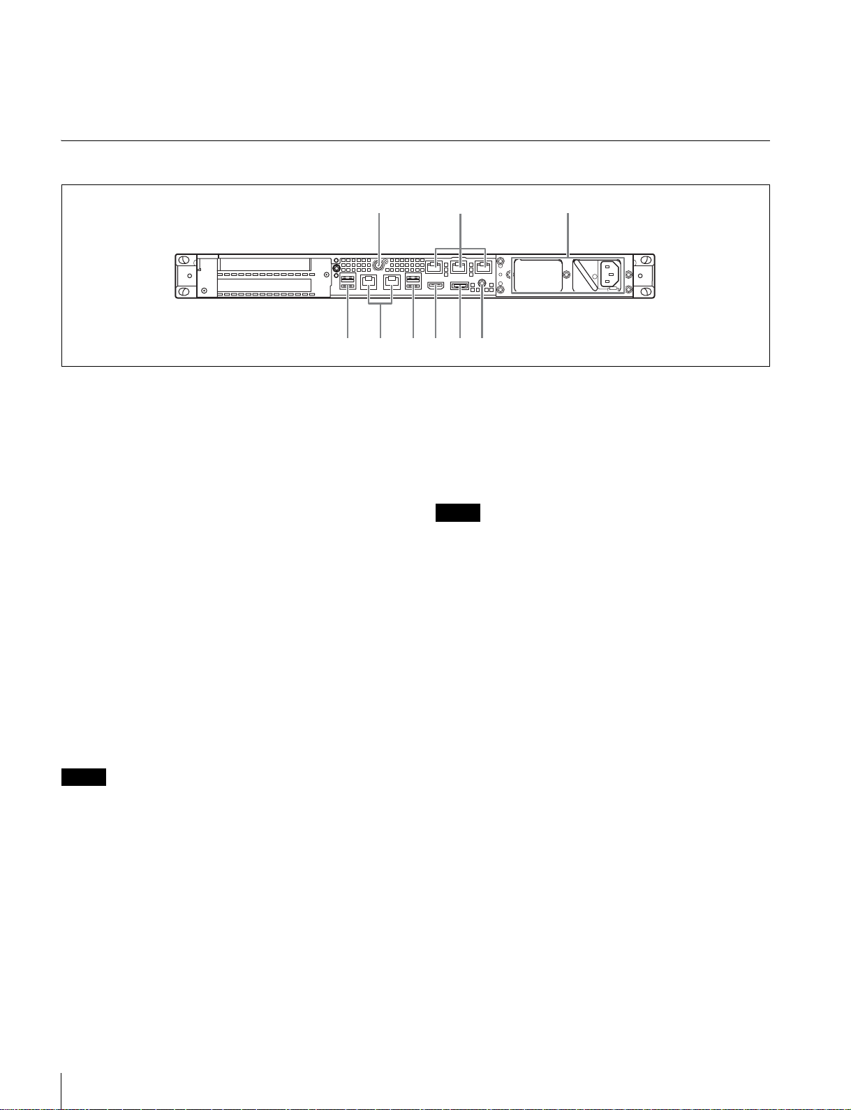
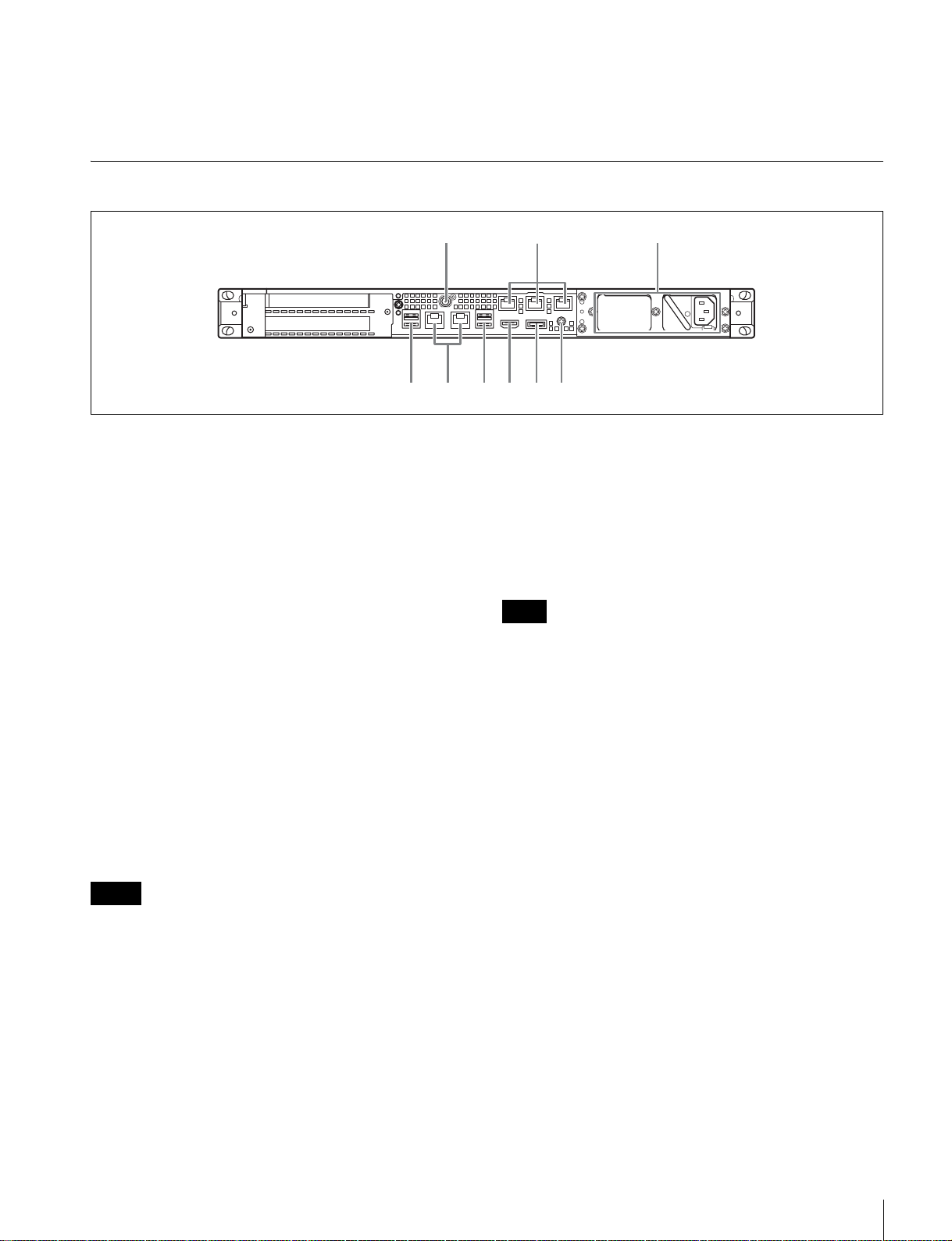
背面
LAN1 LAN2
454678
c TEMP インジケーター
本機内部温度の異常上昇を検出した場合に赤く点灯します。
112 3
a SYSTEMTC 端子
本システムでは使用しません。
b Remote 端子(1/2、3/4、5)
本システムでは使用しません。
c AC 電源ユニット
電源コードを挿入して、電源コンセントに接続します。
工場出荷時は、AC電源ユニットが 1つ装着されています。
別売の電源ユニットを追加装着することによって、電源を
二重化することができます。信頼性が要求されるシステム
で本機を使用するとき、一方の電源ユニットが故障しても
運用の継続が可能です。
◆ 電源ユニットの追加または交換については、ソニーのサービス
担当者または営業担当者にご連絡ください。
d USB 端子(背面)
本書で説明されていない USB 機器については対応していま
せん。
ご注意
g DisplayPort 端子
DisplayPort − DVI 変換ケーブルまたは DisplayPort −
HDMI 変換ケーブルでディスプレイに接続します。
変換ケーブルは、アクティブタイプのケーブルを使用して
ください。
ご注意
DisplayPort ケーブルをご使用の場合は、以下の推奨ケーブルを使
用してください。
• LINDY 社製型番 416304K 対応DisplayPort ケーブル(1 m)
h アース端子
アースを接続します。
• 背面の 4 つの USB 端子のうち、右下のポートのみ給電に対応して
います(900mA)。他の 3 ポートは給電非対応ですので、USB
端子からの電力供給が不要な USB 機器を接続してください。
• ケーブルは、SuperSpeedUSB ケーブルをご使用ください。
e LAN 端子
ギガビットイーサネットに接続します。
f HDMI 端子
HDMI ケーブルでディスプレイに接続します。
HDMI ケーブルは、ソニー製ケーブルをご使用ください。
推奨ケーブル(例):HIGHSPEEDHDMI ケーブル
DLC-HE20XF(2m)
各部の名称と働き
6

準備
2
[DateandTime]タブの[Changetimezone]をク
リックして、タイムゾーンを選択する。
3
[DateandTime]タブの[Changedateandtime]を
クリックして、日付と時刻を設定する。
初期設定
本機を使用する前に、本機内の Windows の設定を行いま
す。設定方法については、標準的な Windows8.1 の操作方
法に準じます。
ご注意
本機を再起動する場合は、Windows の再起動ではなく、いったん
シャットダウンさせてから、前面のオン / スタンバイボタンを再
度オンにしてください。
1
前面の USB 端子にキーボードとマウスを接続し、背面
の HDMI 端子にディスプレイを接続する。
2
本体のオン / スタンバイボタンをオンにする。
3
Windows のサインイン画面が表示されたら、ユーザー名
「nm1」、パスワード「pws100nm1」でサインインする。
ネットワークを設定する
1
本機背面の LAN 端子に LAN ケーブルを接続し、ネット
ワークに接続する。
4
[InternetTime]タブの[Changesettings]ボタンを
クリックする。
5
NTP サーバーを設定し、[UpdateNow]ボタンをク
リックする。
6
定期的に NTP サーバーで時刻を補正する場合は、
[SynchronizewithanInternettimeserver]をチェッ
クする。
ユーザーのパスワードを変更する
本機内蔵の Windows には、工場出荷時に次のユーザーが
設定されています。セキュリティのため、これらのユー
ザーのパスワードを変更してください。
ユーザー名 権限 パスワード
nm1 管理者 pws100nm1
nm1user 一般ユーザー pws100nm1user
使用環境によってはネットワーク上の意図せぬ第三者から製品に
アクセスされる可能性があります。セキュリティーの面からすべ
てのパスワードを設定することを強く推奨します。
下記に従って、すべてのパスワードを設定してください。
2
コントロールパネルの[NetworkandInternet]−
[Viewnetworkstatusandtasks]をクリックする。
3
[Connections]の[LAN1/2]をクリックする。
4
[Properties]ボタンをクリックする。
5
[InternetProtocolVersion4(TCP/IPv4)]を選択して、
[Properties]ボタンをクリックする。
6
IP アドレスなどの設定を変更する。
7
DNS、WINS などの設定を行う場合は、[Advanced]
ボタンをクリックする。
8
設定が完了したら、[OK]ボタンをクリックする。
日時を設定する
1
コントロールパネルの[Clock,Language,andRegion]
で[DateandTime]−[Setthetimeanddate]を選
択する。
1
コントロールパネルの[UserAccountsandFamily
Safety]をクリックする。
2
[UserAccount]の[Changeaccounttype]をクリッ
クする。
3
ユーザー「nm1」または「nm1user」を選択する。
4
[Changethepassword]をクリックする。
5
現在のパスワードと新しいパスワード、ヒントを入力
し、[ChangePassword]ボタンをクリックする。
サインアウトする
設定が完了したら、Windows からサインアウトします。
1
マウスカーソルを画面の右上に移動してチャームを表
示し、[Start]をクリックする。
2
画面右上のアカウント名をクリックし、[Signout]を
クリックする。
準備
7

Web メニューの表示
本機の設定・操作は、クライアント PC からネットワーク
を介して本機に接続し、クライアント PC の Webブラウ
ザーに Webメニューを表示して行います。
クライアント PC の推奨環境
CPU:Corei53GHz 以上
メモリー:4GB以上
OS: Windows7Professional64 ビット
Windows8.1Pro64 ビット
Windows1064 ビット
Webブラウザー:GoogleChrome で動作を確認していま
す。必要に応じて、最新のバージョンにアップデート
してお使いください。
ディスプレイ:1920 × 1080 以上を推奨
コンピューターの Webブラウザーのアドレス欄に「https:/
/(IP アドレス)」(「ネットワークを設定する」で設定した
IP アドレス)と入力して、Webメニューを表示させます。
ログイン画面が表示されたら、ユーザー名とパスワードを
入力してログインします。
工場出荷時は、下記のユーザー名とパスワードが設定され
ています。
ユーザー名:admin
パスワード:nxladmin1
証明書(クライアント証明書)を Web ブラウザーにインス
トールする必要があります。
クライアント PC に証明書をインストールする手順の例を
以下に示します。
ルート CA 証明書のインストール手順
1
本機にログインし、Web ブラウザーで Web メニューに
https 接続する。
2
アドレスバーの左側にある鍵アイコンをクリックする。
3
ポップアップ画面から[Connection]タブを選択し、
[Certificateinformation]をクリックする。
[Certificate]ダイアログが表示されます。発行先の
「PWS-100NM1- <シリアル番号>」をメモしておきま
す。
4
[CertificationPath]タブをクリックしてから、
[CCSRootCA1]を選択し、[ViewCertificate]をク
リックする。
5
表示された CCSRootCA1 の[Certificate]ダイアログか
ら[Details]タブをクリックし、[CopytoFile]ボタ
ンをクリックする。
CCSRootCA1 の証明書をエクスポートするウィザード
が表示されます。
システム設定
Web メニューの設定画面で、本システムの設定を行いま
す。
Web メニューにログインする際は、管理者権限のあるユー
ザーでログインしてください。
なお、Web メニューでの操作について詳しくは、Web メ
ニューのヘルプをご覧ください。
ユーザーの追加
デフォルトの admin 以外にオペレーターなどのアカウント
を追加するには、設定画面の[user]ページで新規ユー
ザーを追加してください。
クライアント PC に証明書をインス
トールする
クライアント PC の Web ブラウザーから https 接続で Web
メニューを表示すると、「この接続ではプライバシーが保護
されません」などの警告メッセージが出力されます。警告
なしで https 接続を行うためには、サーバー
(PWS-100NM1- <シリアル番号>)に対応したルート CA
6
[Next]をクリックする。
7
「DERencodedbinaryX.509(.CER)」を選択し、[Next]
をクリックする。
8
[Browse]ボタンをクリックして証明書を保存する
フォルダーを設定し、[Next]をクリックする。
証明書のエクスポートが始まります。
9
完了の画面が表示されたら、[Finish]をクリックす
る。
10
メッセージが表示されたら、[OK]をクリックする。
表示されている[Certificate]ダイアログはすべて
[OK]をクリックして閉じる
11
エクスポートした証明書を USB メモリーに入れ、その
USB メモリーをクライアント PC に装着し、証明書を
クライアント PC の任意のフォルダー(デスクトップ
など)にコピーする。
準備
8

12
クライアントPC で GoogleChromeを起動し、Chromeの
設定ボタンをクリックし、メニューから[設定]を選
択する。
13
設定画面で[詳細設定を表示]をクリックし、
[HTTPS/SSL]の下の[証明書の管理]ボタンをク
リックする。
[証明書]ダイアログが表示されます。
14
ダイアログの[信頼されたルート証明機関]タブをク
リックし、[インポート]ボタンをクリックする。
証明書をインポートするウィザードが表示されます。
15
[次へ]をクリックする。
16
[参照]ボタンをクリックして本機からコピーした証明
書ファイルを選択し、[次へ]をクリックする。
17
[証明書をすべて次のストアに配置する]が選択されて
おり、[証明書ストア]に「信頼されたルート証明機
関」と表示されていることを確認して、[次へ]をク
リックする。セキュリティ警告が表示された場合は
[はい]をクリックする。
ライブラリ等のライセンスについて
PWS-110NM1 が使用する各種ライブラリ等のライセンスに
ついては、Web メニューの[Help]から確認できます。
証明書のインポートが始まります。
18
完了の画面が表示されたら、[完了]をクリックする。
ウィザードが終了します。
19
メッセージが表示されたら、[OK]をクリックする。
20
[閉じる]をクリックして[証明書]ダイアログを閉じ
てから、Chrome を再起動する。
証明書のインストール後に Web メニューを
表示する
1
クライアント PC で名前解決の設定を行う。
DNS 機能を使用するか、hosts ファイルに登録するな
どの方法で、「ネットワークを設定する」(7 ページ)
で設定した IP アドレスと、手順 3 でメモした発行先の
「PWS-100NM1-<シリアル番号>」との間の名前解決
を設定します。
2
Web ブラウザーを起動し、下記の URL を開く。
https://pws-100nm1-<シリアル番号>
準備
9

メンテナンスアプリケー
ションの操作
使用上のご注意
電源に関する注意事項
システム管理者向けメンテナンスアプリケーション
(MaintenanceWebApplication)の操作については、本機
にサインインしてデスクトップ上にあるショートカットを
開いてマニュアルを参照してください。
本機が動作中に突然電源が切れた場合、データが壊れる可
能性があります。データ保護のため、UPS(無停電電源装
置)のご使用をお勧めします。
また、電源コードを抜く場合やブレーカーを落とす場合は、
必ず事前に本機のオン / スタンバイボタンを押して本機の
動作を停止させてください。
有寿命部品についての注意事項
ファン、バッテリーは有寿命部品として定期的な交換が必
要です。
常温でのご使用の場合、2 〜 5 年を目安に交換してくださ
い。ただし、交換時期は目安であり、部品の寿命を保証す
るものではありません。交換の際はお買い上げ店にご相談
ください。
USB デバイスに関する注意事項
自給電タイプの USB デバイスを接続して使用する場合、デ
バイスの電源がオンになるタイミングによっては、そのデ
バイスを認識できない場合があります。その場合は USB デ
バイスの電源を入れ直すか、USB ケーブルを抜いて接続し
直してください。
本機は、UASP(USBAttachedSCSIProtocol)に対応して
いません。
ネットワーク対応機器に対する注意事項
使用環境によってはネットワーク上の意図せぬ第三者から
アクセスされる可能性があります。
セキュリティの面からすべてのパスワードを設定すること
を強く推奨します。
7 ページの手順に従って、すべてのパスワードを設定して
ください。
セキュリティの面から、製品をネットワークに接続してご
使用になる際は、ブラウザでコントロール画面にアクセス
し、アクセス制限設定を工場出荷時の設定値から変更して
設定することを強く推奨します。(8 ページ)
また、定期的にパスワードを変更することを推奨します。
設定作業中または設定作業後のブラウザで他のサイトを閲
覧しないでください。ブラウザにログインした状態が残り
ますので、意図しない第三者の使用や悪意のあるプログラ
ムの実行を防ぐために、設定作業が完了したら必ずブラウ
ザを終了してください。
メンテナンスアプリケーションの操作/使用上のご注意
10
仕様
一般
電源 AC100V 〜240V
50/60Hz
消費電力 235W
待機電力 3W 以下
使用温度 5 ℃〜35 ℃
保存温度 −20 ℃〜+60 ℃
使用湿度 20%〜90%(相対湿度)
保存湿度 5%〜80%
質量 10.4kg
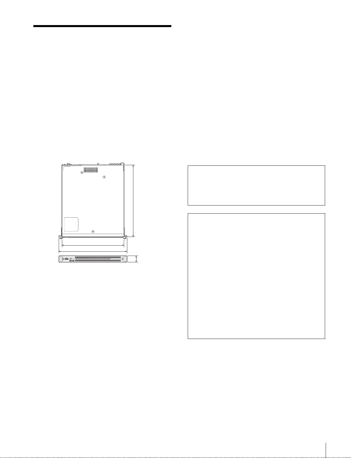
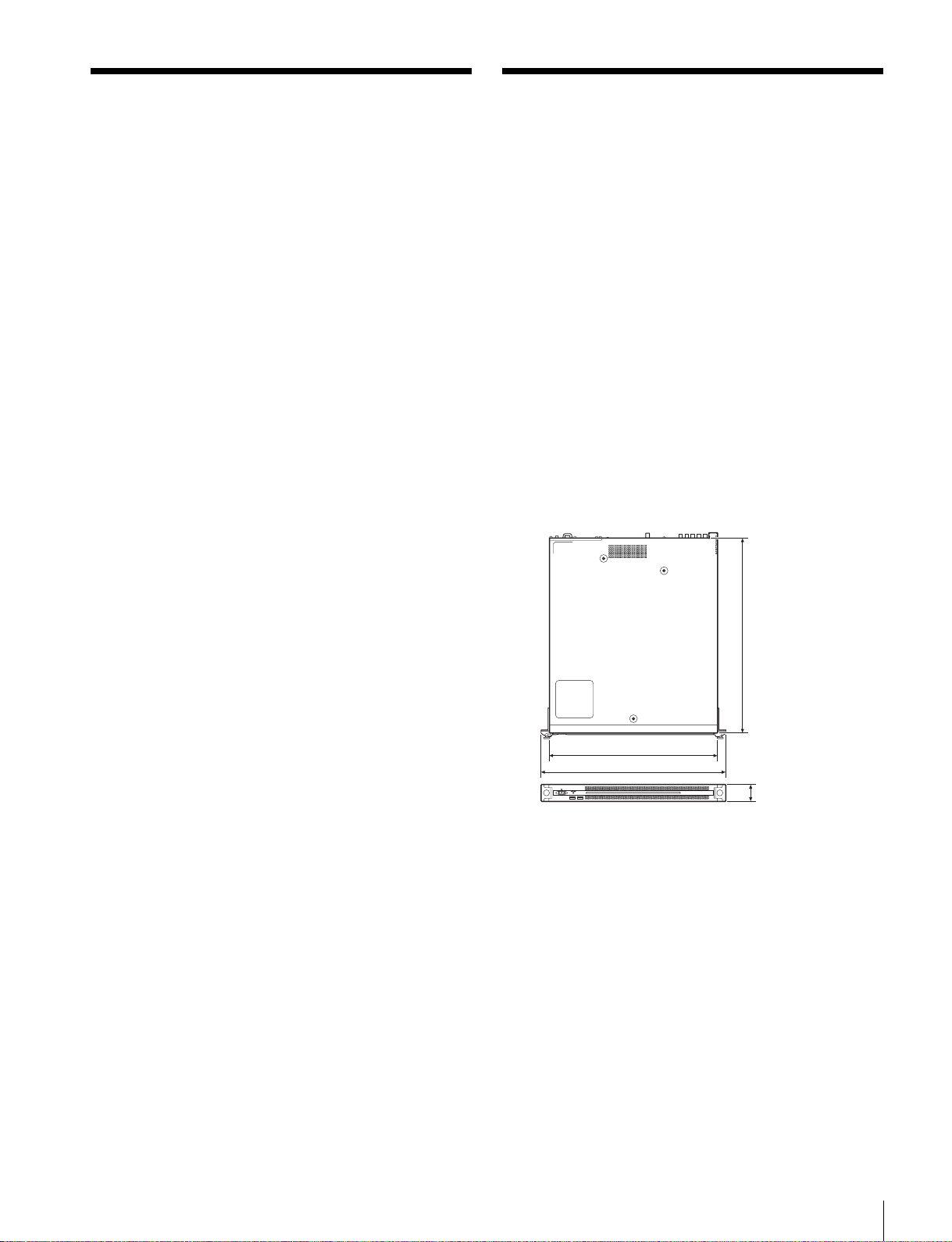
外形寸法 440×43.6× 507mm(幅/高さ/奥行き)
単位:mm
507
HDMI TypeA(1)
HDMIVer.1.4a、
最大解像度 1920 × 1200、60Hz
DisplayPort DisplayPort(1)
DisplayPortVer.1.1a、
最大解像度 2560 × 1600、60Hz
付属品
オペレーションマニュアル(本書)(1)
オペレーションガイド(1)
ラックマウント用ネジ(4)
仕様および外観は、改良のため予告なく変更することがあ
りますが、ご了承ください。
通信を行う機器でセキュリティ対策を行わなかった結果、
または、通信仕様上の、やむを得ない事情により、デー
タ漏洩等、セキュリティ上の問題が発生した場合、弊社
ではそれによって生じたあらゆる損害に対する責任を負
いかねます。
440
482
43.6
CPU
プロセッサー IntelCorei76700TE(2.4GHz)
メモリ 8GBytes
SO-DIMM(DDR4)(2)
ドライブ(M.2)
120GBytes
拡張バス PCIeGen28Lane(30W)(2)
入出力
LAN RJ-45(2)
1000BASE-T
100BASE-TX
USB(前面 / 背面)
SuperSpeedUSB(USB3.0)TypeA
(6、うち前面 2、背面 4)
前面:給電対応(各 900 mA)
背面:右下のポートのみ給電対応
(900 mA)、他 3 ポートは給電非対応
• 必ず事前に記録テストを行い、正常に記録されている
ことを確認してください。本機や記録メディア、外部
ストレージなどを使用中、万一これらの不具合により
記録されなかった場合の記録内容の補償については、
ご容赦ください。
• お使いになる前に、必ず動作確認を行ってください。
故障その他に伴う営業上の機会損失等は保証期間中お
よび保証期間経過後にかかわらず、補償はいたしかね
ますのでご了承ください。
• 本製品を使用したことによるお客様、または第三者か
らのいかなる請求についても、当社は一切の責任を負
いかねます。
• 本機内、記録メディア、外部のストレージ等に記録さ
れたデータの損失、修復、複製の責任は負いかねます。
• 諸事情による本製品に関連するサービスの停止、中断
について、一切の責任を負いかねます。
• Windows は、米国 MicrosoftCorporation の米国およびそ
の他の国における登録商標または商標です。
• Ethernet(イーサネット)は、富士ゼロックス株式会社
の登録商標です。
• GoogleChrome は GoogleInc. の商標または登録商標です。
• HDMI、HDMIHigh-DefinitionMultimediaInterface およ
び HDMIロゴは、HDMILicensingLLCの商標もしくは
米国およびその他の国における登録商標です。
• Dante は、AudinatePtyLtd の登録商標です。
仕様
11

その他、本書に記載されているシステム名、製品名、会社
名は一般に各開発メーカーの登録商標または商標です。な
お、本文中では、®、™ マークは明記していません。
本製品は、トロンフォーラム(www.tron.org)の
T-License2.1 に基づき T-Kernel2.0 ソースコードを利用し
ています。
12
仕様

English
Table of Contents
Overview ............................................................................. 14
System Configuration Examples............................................ 15
Name and Function of Parts............................................... 16
Front View..............................................................................16
Front View (Panel Removed)................................................. 16
Rear View............................................................................... 17
Setting Up ........................................................................... 18
Initial Settings........................................................................ 18
Displaying the Web Application ........................................... 18
System Settings ..................................................................... 19
Installing Certificates on a Client PC.................................... 19
Library Licenses .................................................................... 20
Maintenance Web Application Operation ........................ 20
Usage Precautions............................................................. 21
Specifications..................................................................... 21
For safety, please read the precautions described in the PWS-110 Operation
Guide (supplied).
GBGB
Table of Contents
13

Overview
This unit is a system component for controlling the routing
of video and audio signals using IP Live System Manager.
It connects to Networked Media Interface devices (herein
referred to as NMI devices) or IP audio devices that
support the Dante protocol (herein referred to as Dante
devices) connected by IP network connections (such as
Ethernet) via general-purpose network switches, and
controls the routing of video and audio input/output
signals between the NMI devices or between Dante
devices.
The unit features the following functions.
Routing control between NMI devices and
between Dante devices
You can control the routing of video and audio input/
output signals between NMI devices or between Dante
devices connected by IP network connection via generalpurpose network switches.
Settings management for devices
NMI device settings can be viewed and changed from the
GUI screens of IP Live System Manager. Dante device
settings can also be viewed.
Role-based user management
Users can be managed based on their roles using the three
available categories; “Administrator” (system
administrators), “Manager” (operation managers), and
“Operator” (operators).
Workgroup management based on use case
You can group users and virtual interfaces for video and
audio streaming input/outputs of NMI devices and Dante
devices into workgroups, according to the content of the
video and audio, and then activate/manage workgroups
according to the use case.
Network topology monitoring
You can visualize the network topology information of
devices that are connected to each other via a generalpurpose network switch and monitor the packet flow rates
of the network switch ports, as well as display packet loss
and other network errors.
Web GUI
Operations and settings for the IP Live System Manager
software installed on the unit can be performed via GUI
displayed in a web browser on a client PC.
14
Overview
System Configuration Examples
Connect the LAN connectors of the unit with the LAN
connectors of the network switches using Ethernet cables.
Likewise, connect the LAN connectors of the NMI devices
and Dante devices with the LAN connectors of the
Administrator Manager
Network switch for
NMI devices
(10 GbE)
AV server
Operator
network switches using Ethernet cables. In addition,
connect the client PC to the network switch to allow
operation of the PWS-110NM1 via GUI displayed in a
web browser on the client PC.
PWS-110NM1
Network switch for
Dante devices
(1 GbE)
Audio Mux/Demux
board
IP Audio device
(Dante compatible)
I/O switcherSystem camera
Overview
15
Name and Function of Parts
Front View
12 3
4
a On/Standby button and indicator
Switches the unit on/off (standby state). Connecting the
power cord places the unit in standby state, and the
indicator turns on red. Pressing the On/Standby button
while in standby state turns on the unit and the indicator
turns on green. Pressing and holding the On/Standby
button for two seconds switches the unit to standby state,
and the indicator changes to red. To turn the unit on again
after switching from On state to standby state, when the
indicator is red, press and hold the On/Standby button for
three seconds or longer. The indicator goes out when the
power cord is disconnected.
b SYSTEM indicator
Indicates the status of the unit.
Green: Operating normally
Flashing green (once per second): System is booting or
transitioning to standby state.
Front View (Panel Removed)
When the SYSTEM indicator or web application indicates
an error, you can remove the front panel to check the status
of the hardware components.
Flashing orange (once per second): A warning has been
generated.
High-speed flashing red (four times per second): An
error has occurred.
c Front panel LED
Turns on according to settings in the web application. The
LED is configured using [001: LINE LED] in the
[Settings] page on the Maintenance screen.
d USB connectors (front panel)
Connects to a keyboard and mouse for initializing the unit.
USB devices not described in this document are not supported.
Notes
• Both USB ports on the front panel support power delivery (900 mA).
• Use SuperSpeed USB cables.
To remove the front panel, loosen the screws on the left
and right sides and pull the panel towards you.
123
a FAN indicators
If any of the fans fail, the corresponding fan indicator turns
on red.
16
Name and Function of Parts
b POWER indicators
If either of the AC power supply units fail, the
corresponding indicator turns on red.
c TEMP indicator
If an abnormally high temperature is detected within the
unit, the indicator turns on red.
Rear View
112 3
LAN1 LAN2
454678
a SYSTEM TC connector
Not used by this system.
b Remote connectors (1/2, 3/4, 5)
Not used by this system.
c AC power supply units
Insert the power cords and connect to power outlets.
Only one AC power supply unit is installed at the factory.
A second optional power supply unit can be installed to
provide power supply redundancy. When used in systems
that require reliability, power supply redundancy allows
the unit to continue operating even if a power supply unit
fails.
For details about installing or replacing a power supply
unit, consult your Sony sales or service representative.
d USB connectors (rear panel)
USB devices not described in this document are not
supported.
Notes
• Of the four USB connectors on the rear panel, only the bottom right port
supports power delivery (900 mA). The other three ports do not support
power delivery, and should be used to connect USB devices that do not
require power supplied from the USB connector.
• Use SuperSpeed USB cables.
Recommended cable (example): DLC-HE20XF
HIGH SPEED HDMI cable (2 m (6 ft.))
g DisplayPort connector
Connect to a monitor using a DisplayPort-to-DVI
converter cable or DisplayPort-to-HDMI converter cable.
Use an active-type converter cable.
Note
If using a DisplayPort cable, use the following recommended cable.
• LINDY 41630 4K-compatible DisplayPort cable (1 m (3 ft.))
h Ground terminal
Connect to ground.
e LAN connectors
Connect to a Gigabit Ethernet network.
f HDMI connector
Connect to a monitor using an HDMI cable.
Use only Sony-brand HDMI cables.
Name and Function of Parts
17

Setting Up
Initial Settings
Before using the unit, configure the Windows settings
within the unit. The description below describes the
standard settings in Windows 8.1.
Note
To reboot the unit, first shut down the unit and then turn the On/Standby
button on the front panel on again, without rebooting Windows.
1
Connect a keyboard and mouse to the USB connectors
on the front panel, and connect a monitor to the HDMI
connector on the rear panel.
3
Click [Change date and time] on the [Date and Time]
tab, and set the date and time.
4
Click the [Change settings] button on the [Internet
Time] tab.
5
Specify an NTP server, then click the [Update Now]
button.
6
Place a check mark in [Synchronize with an Internet
time server] to periodically correct the clock using the
NTP server.
Changing user passwords
The following default users are configured for Windows
within the unit. Change the password for the user to
provide security.
2
Set the On/Standby button to the On position.
3
When the Windows sign-in screen appears, enter
“nm1” as the user name, enter “pws100nm1” as the
password, and sign in.
Configuring the network
1
Connect a LAN cable to the LAN connector on the rear
panel of the unit, and connect the other end to the
network.
2
Click [View network status and tasks] under [Network
and Internet] in the control panel.
3
Click [Connections] > [LAN 1/2].
4
Click the [Properties] button.
5
Select [Internet Protocol Version 4 (TCP/IPv4)], then
click the [Properties] button.
6
Change the IP address and other settings.
User name Privileges Password
nm1 Administrator pws100nm1
nm1user General user pws100nm1user
Depending on the operating environment, unauthorized
third parties on the network may be able to access the unit.
For security, we strongly recommend changing all the
default passwords as follows.
1
Click [User Accounts and Family Safety] in the
control panel.
2
Click [User Account] > [Change account type].
3
Select the “nm1” or “nm1user” user.
4
Click [Change the password].
5
Enter the current password, a new password and a
password hint, then click the [Change Password]
button.
Signing out
When finished, sign out from Windows.
7
Click the [Advanced] button to configure DNS,
WINS, and other settings.
8
When finished, click the [OK] button.
Setting the date and time
1
Select [Set the time and date] under [Date and Time]
in the [Clock, Language, and Region] control panel.
2
Click [Change time zone] on the [Date and Time] tab,
and select the time zone.
18
Setting Up
1
Move the mouse cursor to the top right corner of the
screen to display the Charms bar, then click [Start].
2
Click the account name on the top right of the screen,
then click [Sign out].
Displaying the Web Application
You connect to the unit via the network from a client PC
and use the web application in a web browser on the client
PC to control and configure the unit.

Recommended client PC environment
CPU: Core i5 3 GHz or higher
Memory: 4 GB or higher
OS: Windows 7 Professional 64-bit
Windows 8.1 Pro 64-bit
Windows 10 64-bit
Web browser: Operation with Google Chrome has been
verified. Update to the latest version, as required.
Display resolution: 1920 x 1080 pixels or higher is
recommended
Enter “https://(IP_address)” in the address bar of a web
browser on the computer (where IP_address is the address
specified in “Configuring the network”) to display the
web application.
Enter the user name and password when the login screen
appears.
The following user name and password are configured by
default.
User name: admin
Password: nxladmin1
2
Click the lock icon on the left hand end of the address
bar.
3
Select the [Connection] tab in the popup window, then
click [Certificate information].
The [Certificate] dialog box appears. Make a note of
the certificate issuer “PWS-100NM1<serial_number>” in the dialog box.
4
Click the [Certification Path] tab, select
[CCSRootCA1], then click [View Certificate].
5
Click the [Details] tab in the CCSRootCA1
[Certificate] dialog box that appears, then click the
[Copy to File] button.
The CCSRootCA1 Certificate Export Wizard appears.
6
Click [Next].
7
Select “DER encoded binary X.509 (.CER),” then
click [Next].
System Settings
Configure the system on the Setting screen in the web
application.
Log in as a user with administrator privileges when
logging in to the web application.
For details about operating the web application, refer to the
Help of the application.
Adding users
To add user accounts in addition to the default admin
account, add new users on the [Users] page of the Setting
screen.
Installing Certificates on a Client PC
Displaying the web application using an https connection
from a web browser on the client PC may display a
warning, such as “Your connection is not private”. To
connect successfully via https without the warning, a root
CA certificate (client certificate) corresponding to the
server (PWS-100NM1-<serial_number>) must be
installed in the web browser.
The following describes the procedure for installing a
certificate on a client PC.
8
Click the [Browse] button and specify a folder in
which to store the certificate, then click [Next].
Exporting of the certificate commences.
9
When the export wizard completion window appears,
click [Finish].
10
When the message window appears, click [OK]. Click
[OK] in all the [Certificate] dialog boxes that appear to
close them.
11
Copy the exported certificate onto a USB storage
device, connect that device to the client PC, then copy
the certificate to any location (e.g., desktop) on the
client PC.
12
Start Google Chrome on the client PC, click the
Chrome menu button, then select [Settings] from the
menu.
13
Click [Show advanced settings] on the Settings screen,
then click the [Manage certificates] button under
[HTTPS/SSL].
The [Certificates] dialog appears.
Root CA certificate installation procedure
1
Log into the unit, then access the web application
using https in a web browser.
14
Click the [Trusted Root Certification Authorities] tab
of the dialog, then click the [Import] button.
The Certificate Import Wizard appears.
15
Click [Next].
Setting Up
19

16
Click the [Browse] button and select the certificate file
you copied from the unit, then click [Next].
17
Check that [Place all certificates in the following
store] is selected and that “Trusted Root Certification
Authorities” is displayed in [Certificate store:], then
click [Next]. If a security warning appears, click [Yes].
Importing of the certificate commences.
18
When the import wizard completion window appears,
click [Finish].
The wizard exits.
19
When the message window appears, click [OK].
20
Click [Close] to close the [Certificate] dialog box, then
restart Chrome.
Displaying the web application after
installing certificates
1
Configure name resolution settings on the client PC.
Maintenance Web
Application Operation
For details about the operation of the Maintenance Web
Application for system administrators, sign in to the unit
and double-click the desktop shortcut to browse the
manual.
Configure name resolution between the IP address you
configured in “Configuring the network” (page 18)
and the certificate issuer “PWS-100NM1<serial_number>” you made a note of in step 3 by
using DNS functions, registering to the hosts file, or
using other methods.
2
Start a web browser, then access the following URL.
https://pws-100nm1-<serial_number>
Library Licenses
Refer to the [Help] menu in the web application for the
licenses of each type of library used by the PWS-110NM1.
20
Maintenance Web Application Operation
Usage Precautions
Specifications
Power supply precautions
If the unit is suddenly turned off during operation, data loss
may occur. To maintain data integrity, the use of an
uninterruptible power supply (UPS) is recommended.
To disconnect the power cord or turn off the breaker,
always press the On/Standby button on the unit to stop the
unit before proceeding.
Components with limited lifespan
The fan and battery are consumable parts that will need
periodic replacement.
When operating at room temperature, a normal
replacement cycle will be about 2 to 5 years.
However, this replacement cycle represents only a general
guideline and does not imply that the life expectancy of
these parts is guaranteed. For details on parts replacement,
contact your dealer.
USB device precautions
When using the unit when connected to a self-powered
USB device, the device may not be recognized, depending
on the timing of when the device is turned on. If this
occurs, turn the USB device off and on again, or
disconnect and reconnect the USB cable.
The unit does not support UASP (USB Attached SCSI
Protocol).
General
Power requirement
100 V to 240 V AC
50/60 Hz
Power consumption
235 W
Standby power consumption
3W or lower
Operating temperature
5 °C to 35 °C (41 °F to 95 °F)
Storage temperature
–20 °C to +60 °C (−4 °F to +140 °F)
Operating humidity
20% to 90% (relative humidity)
Storage humidity
5% to 80%
Mass 10.4 kg (22 lb. 15 oz.)
Dimensions 440 × 43.6 × 507 mm (17
20 in.) (width / height / depth)
Unit: mm (in.)
507 (20)
3
/8 × 13/4 ×
Precautions for network-enabled devices
Depending on the operating environment, unauthorized
third parties on the network may be able to access the
system.
We strongly recommend configuring all of the passwords
for security purposes.
Configure all the passwords following the procedure on
page 18.
From a safety standpoint, when using the unit connected
with the network, it is strongly recommended to access the
Control window via a Web browser and change the access
limitation settings from the factory preset values
(page 18).
Changing the password regularly is also recommended.
Do not browse any other website in the Web browser while
making settings or after making settings. Since the login
status remains in the Web browser, close the Web browser
when you complete the settings to prevent unauthorized
third parties from using the unit or harmful programs from
running.
3
482 (19)
/8)
43.6 (1
3
/4)
440 (17
CPU
Processor Intel Core i7 6700TE (2.4 GHz)
Memory 8 GBytes
SO-DIMM (DDR4) (2)
Drive (M.2) 120 GBytes
Expansion bus PCIe Gen2 8Lane (30 W) (2)
Inputs/outputs
LAN RJ-45 (2)
1000BASE-T
100BASE-TX
Usage Precautions / Specifications
21

USB (front panel/rear panel)
Super Speed USB (USB 3.0) Type A
(6, 2 on front and 4 on rear)
Front: Power delivery support (900 mA/
port)
Rear: Power delivery support on bottom
right port (900 mA), not supported on
other three ports
HDMI Type A (1)
HDMI Ver. 1.4a,
1920 × 1200 maximum resolution,
60 Hz
DisplayPort DisplayPort (1)
DisplayPort Ver. 1.1a,
2560 × 1600 maximum resolution,
60 Hz
Supplied accessories
Operation manual (this document) (1)
Operation guide (1)
Screws for Rack Mount (4)
Design and specifications are subject to change without
notice.
SONY WILL NOT BE LIABLE FOR DAMAGES OF
ANY KIND RESULTING FROM A FAILURE TO
IMPLEMENT PROPER SECURITY MEASURES ON
TRANSMISSION DEVICES, UNAVOIDABLE DATA
LEAKS RESULTING FROM TRANSMISSION
SPECIFICATIONS, OR SECURITY PROBLEMS OF
ANY KIND.
Notes
• Always make a test recording, and verify that it was
recorded successfully.
SONY WILL NOT BE LIABLE FOR DAMAGES OF
ANY KIND INCLUDING, BUT NOT LIMITED TO,
COMPENSATION OR REIMBURSEMENT ON
ACCOUNT OF FAILURE OF THIS UNIT OR ITS
RECORDING MEDIA, EXTERNAL STORAGE
SYSTEMS OR ANY OTHER MEDIA OR
STORAGE SYSTEMS TO RECORD CONTENT OF
ANY TYPE.
• Always verify that the unit is operating properly before
use. SONY WILL NOT BE LIABLE FOR
DAMAGES OF ANY KIND INCLUDING, BUT
NOT LIMITED TO, COMPENSATION OR
REIMBURSEMENT ON ACCOUNT OF THE LOSS
OF PRESENT OR PROSPECTIVE PROFITS DUE
TO FAILURE OF THIS UNIT, EITHER DURING
THE WARRANTY PERIOD OR AFTER
EXPIRATION OF THE WARRANTY, OR FOR
ANY OTHER REASON WHATSOEVER.
• SONY WILL NOT BE LIABLE FOR CLAIMS OF
ANY KIND MADE BY USERS OF THIS UNIT OR
MADE BY THIRD PARTIES.
• SONY WILL NOT BE LIABLE FOR THE LOSS,
REPAIR, OR REPRODUCTION OF ANY DATA
RECORDED ON THE INTERNAL STORAGE
SYSTEM, RECORDING MEDIA, EXTERNAL
STORAGE SYSTEMS OR ANY OTHER MEDIA
OR STORAGE SYSTEMS.
• SONY WILL NOT BE LIABLE FOR THE
TERMINATION OR DISCONTINUATION OF ANY
SERVICES RELATED TO THIS UNIT THAT MAY
RESULT DUE TO CIRCUMSTANCES OF ANY
KIND.
22
• Windows is a registered trademark of Microsoft
Corporation in the United States and other countries.
• Google Chrome is a trademark or registered trademark
of Google Inc.
• The terms HDMI and HDMI High-Definition
Multimedia Interface, and the HDMI Logo are
trademarks or registered trademarks of HDMI Licensing
LLC in the United States and other countries.
• Dante is a trademark of Audinate Pty Ltd.
Other products or system names appearing in this
document are trademarks or registered trademarks of their
respective owners. Further, the ®, or ™ symbols are not
used in the text.
This Product uses the Source Code of T-Kernel 2.0 under
T-License 2.1 granted by TRON Forum (www.tron.org).
Specifications
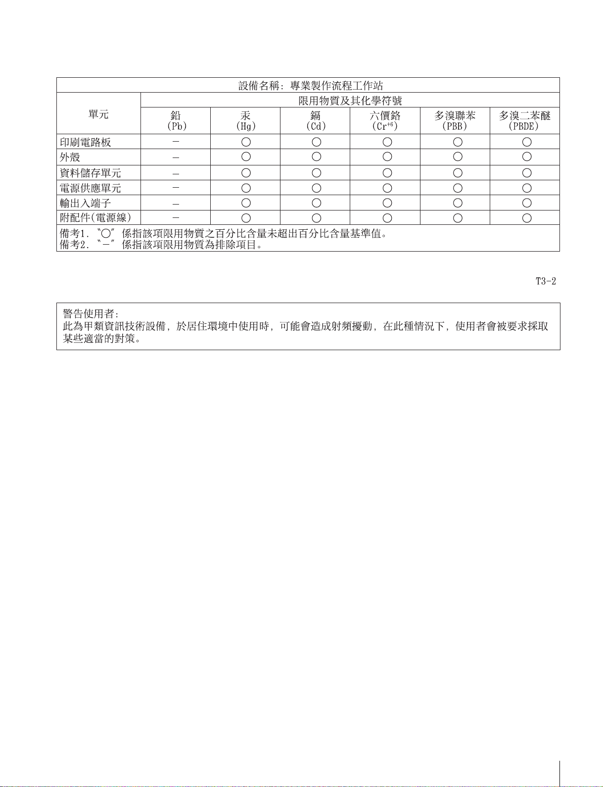
For the customers in Taiwan
Specifications
23

Français
Table des matières
Présentation........................................................................ 25
Exemples de configuration système....................................... 26
Nomenclature.......................................................................27
Vue de face............................................................................. 27
Vue de face (panneau retiré) .................................................. 27
Vue arrière.............................................................................. 28
Mise en service................................................................... 29
Configuration initiale ............................................................ 29
Affichage de l’application web ............................................. 30
Paramètres du système .......................................................... 30
Installation de certificats sur le PC client.............................. 30
Licences de bibliothèque....................................................... 31
Fonctionnement de l’application Maintenance Web....... 32
Précautions d’utilisation.................................................... 32
Spécifications ..................................................................... 33
Afin de garantir votre sécurité, veuillez lire les précautions décrites dans le
guide d’utilisation du PWS-110 (fourni).
24
Table des matières

Présentation
Cet appareil est une composante de système pour le
contrôle du routage de signaux vidéo et audio à l’aide d’IP
Live System Manager. Il connecte des périphériques
d’interface de support en réseau (appelés ici périphériques
NMI) ou des périphériques IP audio qui prennent en
charge le protocole Dante (appelés ici périphériques
Dante) connectés par des connexions réseau IP (comme
Ethernet) via des commutateurs réseau général, et contrôle
le routage des signaux d’entrée/de sortie vidéo et audio
entre les périphériques NMI ou les périphériques Dante.
L’appareil comprend les fonctions suivantes.
Contrôle du routage entre les périphériques NMI
et les périphériques Dante
Vous pouvez commuter le routage des signaux d’entrée/de
sortie vidéo et audio entre les périphériques NMI ou les
périphériques Dante connectés par une connexion réseau
IP via des commutateurs réseau général.
Gestion des réglages pour les périphériques
Les réglages de périphérique NMI peuvent être visualisés
et modifiés à partir des écrans GUI du IP Live System
Manager. Les réglages du périphérique Dante peuvent
également être visualisés.
Gestion d’utilisateur basée sur des rôles
Les utilisateurs peuvent être gérés en fonction de leurs
rôles en utilisant les trois catégories suivantes;
« Administrator » (administrateurs système), « Manager »
(gestionnaires des opérations) et « Operator »
(opérateurs).
Gestion de groupe de travail en fonction du cas
d’utilisation
Vous pouvez grouper des utilisateurs et des interfaces
virtuelles pour les sorties/entrée de flux vidéo et audio des
périphériques NMI et des périphériques Dante dans des
groupes de travail, en fonction du contenu vidéo et audio,
puis vous pouvez activer/gérer les groupes de travail en
fonction du cas d’utilisation.
Contrôle de la topologie du réseau
Vous pouvez visualiser les informations de topologie du
réseau des périphériques connectés entre-eux via un
commutateur réseau général et contrôler le débit du flux de
paquets des ports de commutation de réseau et aussi
afficher la perte de paquets et d’autres erreurs réseau.
GBFR
Interface web
Les opérations et les réglages pour le logiciel IP Live
System Manager installé sur l’appareil peuvent être
effectuées via une interface affichée dans un navigateur
web d’un PC client.
Présentation
25
 Loading...