

Sony PWS-100TD1 Operation Manual

TAPE DIGITIZE STATION
PWS-100TD1
電気製品は、安全のための注意事項を守らないと、火災や人
身事故になることがあります。
このオペレーションマニュアルには、事故を防ぐための重要な注意事項と製品
の取り扱いかたを示してあります。このオペレーションマニュアルをよくお読
みのうえ、製品を安全にお使いください。お読みになったあとは、いつでも見
られるところに必ず保管してください。
OPERATION MANUAL
[Japanese/English/French/German/Italian/Spanish/Chinese/Korean]
1st Edition (Revised 5)

日本語
目次
概要 .................................................................................................................................. 3
システム構成例 ............................................................................................................................................ 4
対応機器...........................................................................................................................9
対応 VTR ..........................................................................................................................................................9
対応 ODS ドライブ.................................................................................................................................... 9
各部の名称と働き ........................................................................................................ 10
前面 .....................................................................................................................................................................10
前面(パネルを外した場合).............................................................................................................10
背面 .....................................................................................................................................................................11
準備 ............................................................................................................................... 12
初期設定...........................................................................................................................................................12
Web メニューの表示..............................................................................................................................14
システム設定................................................................................................................................................14
証明書をインストールする ...............................................................................................................15
ライブラリ等のライセンスについて..........................................................................................15
メンテナンスアプリケーションの操作 ....................................................................................15
使用上のご注意 ............................................................................................................ 16
仕様 ............................................................................................................................... 17
安全のためのご注意が PWS-100 オペレーションガイド(付属)に記載されてい
ますので、ご使用の前にお読みください。
目次
2

概要
本機は、VTR の素材をデジタイズしてクリップを作成し、
オプティカルディスクアーカイブシステムのカートリッジ
などに保存するまでの作業を行うシステムです。本機の機
能を次に示します。
インジェスト
VTR から入力した SDI 信号から高解像度画像とプロキシ
画像のファイルを作成し、内蔵 HDD に保存します。RS422
を使用して、VTR 機器をリモート制御できます。
映像の確認
インジェストしたクリップの画質チェックを自動的に行う
ことができます。また、本機の WebGUI や外部モニターを
使用して、ユーザーの眼で確認することもできます。
クリップの保存
作成した高解像度画像をカートリッジやネットワーク上の
サーバーに転送します。
JP
ワークフロー
インジェストから転送までの一連の作業を一括して実行す
ることができます。また、マネージャーが、実行するタス
クの流れや担当者などをワークオーダーとして定義し、オ
ペレーターにワークオーダーに従って作業をさせることが
できます。
WebGUI
本機の操作や設定は、クライアント PC の Web ブラウザー
に表示される GUI で実行できます。
他ソフトウェアとの連携
カートリッジに保存したクリップのプロパティーやプロキ
シ映像などをエクスポートして、他ソフトウェアで管理す
ることができます。
概要
3
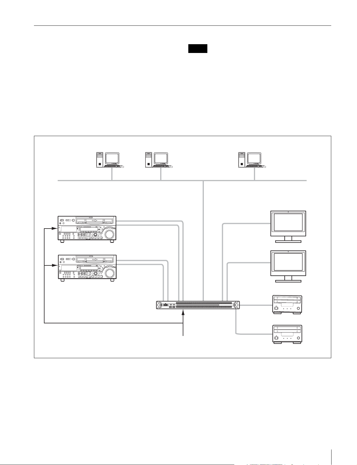
システム構成例
本機の SDI 端子に VTR と外部モニター、背面の USB 端子
にドライブユニットを接続します。Web メニューで SDI の
設定をすることで、2 入力 /2 出力、3 入力 /1 出力、4 入力
のいずれかのシステム構成を選択することができます。
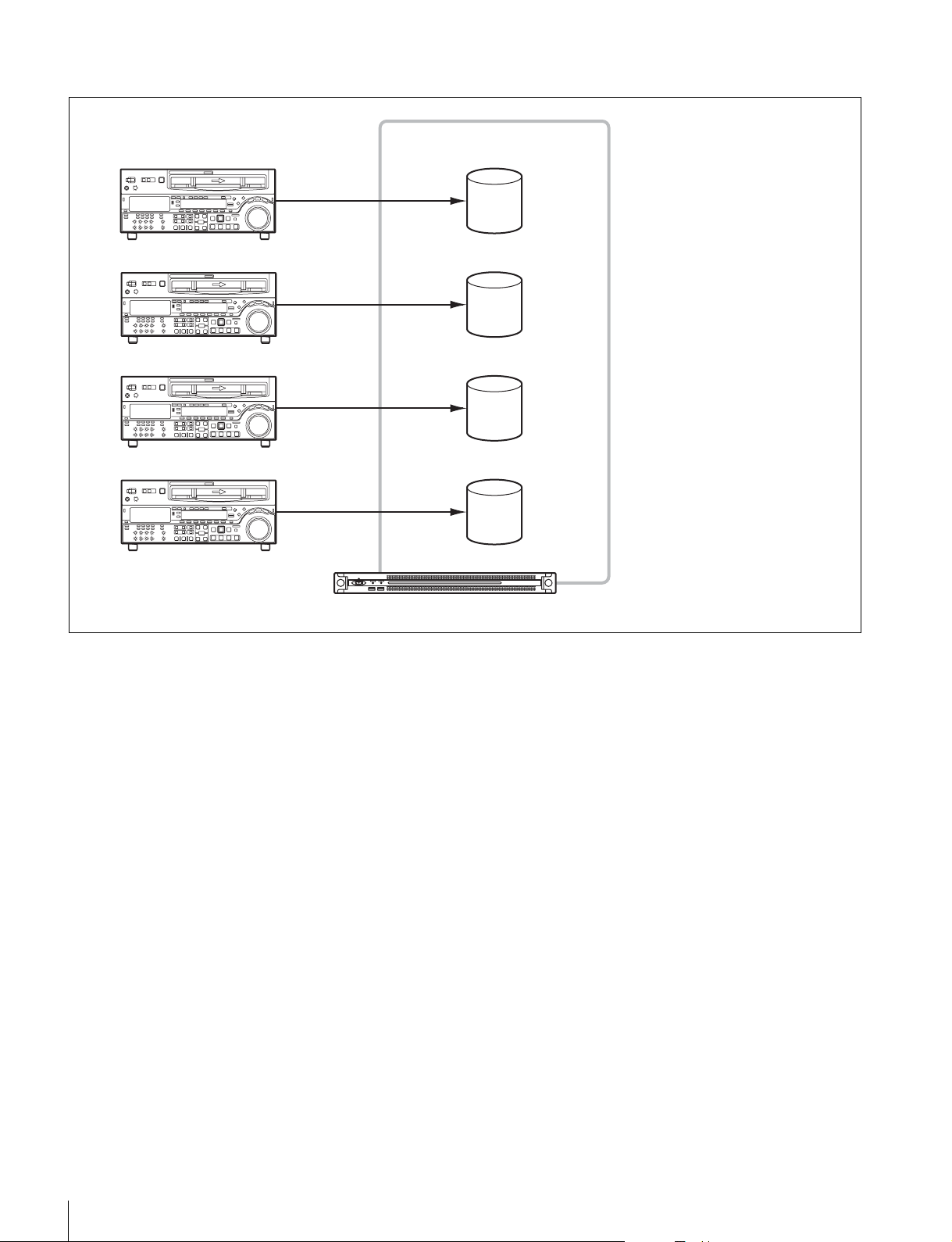
2入力/2出力
SDI1 端子と SDI2 端子に VTR を、SDI3 端子と SDI4 端
子に外部モニターを接続します。2 台の VTR のデジタイズ
を並行して行うことができます。
オペレーター オペレーター マネージャー
VTR
REF
HD/SDSDI
RS422
ご注意
• 複数の VTR 機器を接続する場合、VTR 機器はすべて同期
(± 1H)させてください。
• VTR の EE/PB 設定を PB に設定してください。
ギガビットイーサネット
外部モニター
HDSDI
HD/SDSDI
RS422
REFIN
同期信号
HDSDI
USB3.0
PWS-100TD1
USB3.0
ドライブユニット
概要
4
3入力/1出力
SDI1 〜 3 端子に VTR を、SDI4 端子に外部モニターを接
続します。クリップの高解像度画像の確認は、SDI4 端子
に接続した外部モニターを共用します。
オペレーター オペレーター マネージャー
ギガビットイーサネット
REF
VTR
HD/SDSDI
RS422
HD/SDSDI
RS422
HD/SDSDI
RS422
PWS-100TD1
REFIN
同期信号
外部モニター
HDSDI
USB3.0
USB3.0
ドライブユニット
概要
5
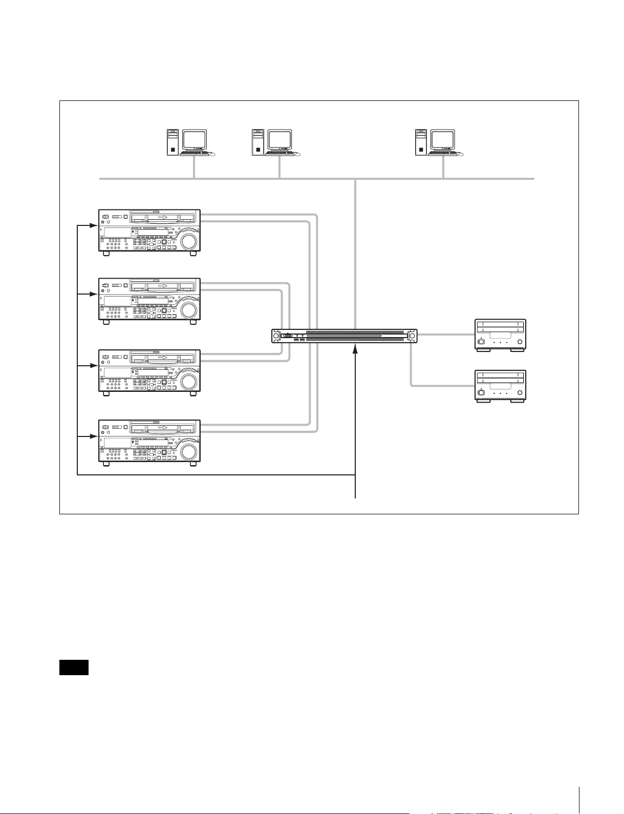
4入力
SDI1 〜 4 端子に VTR を接続します。SDI4 を Ingest とし
て使用していないときに、GUI 上でクリップの高解像度画
像を確認することができます。
オペレーター オペレーター マネージャー
VTR
REF
HD/SDSDI
RS422
HD/SDSDI
RS422
ギガビットイーサネット
HD/SDSDI
RS422
HD/SDSDI
RS422
PWS-100TD1
REFIN
同期信号
USB3.0
USB3.0
ドライブユニット
RAID 構成の選択
システム構成を設定したあと、選択したシステム構成の SDI 入力と論理ドライブの数が同じになるように、RAID の構成を設
定します。
RAID 構成の設定は、PWS-100 メンテナンス Web アプリケーションで行います。選択したシステム構成に従って、次に示す
RAID 構成を設定してください。下記の設定以外では、動作しません。
設定方法について詳しくは、PWS-100 メンテナンス Web アプリケーションのオペレーションマニュアルをご覧ください。
• 2 入力 /2 出力の場合:(5D+1P)× 2
• 3 入力 /1 出力の場合:(3D+1P)× 3
• 4 入力の場合:(2D+1P)× 4
ご注意
RAID 構成の変更を行うと、内蔵ストレージに書き込まれたフルレゾリューションファイル、プロキシファイル、各種レポートファイル、お
よびワークオーダーはすべて消去されます。
RAID 構成の変更の前に、必ずすべてのデータを転送またはダウンロードし、退避させてください。
概要
6
RAID 構成について
PWS-100TD1 は、全部で 12 台の HDD を搭載しており、以下の RAID 構成が可能です。
• 2D+1P:データ用 HDD2 台、パリティ用 HDD1 台の合計 3 台の HDD で一つの論理ドライブを構成し、合計 4 個の論理ドライブ
を持ちます。
• 3D+1P:データ用 HDD3 台、パリティ用 HDD1 台の合計 4 台の HDD で一つの論理ドライブを構成し、合計 3 個の論理ドライブ
を持ちます。
• 5D+1P:データ用 HDD5 台、パリティ用 HDD1 台の合計 6 台の HDD で一つの論理ドライブを構成し、合計 2 個の論理ドライブ
を持ちます。
2 入力 /2 出力の場合
VTR
3 入力 /1 出力の場合
VTR
SDI 入力
SDI 入力
SDI 入力
論理ドライブ(5D + 1P)
外部モニター
SDI 出力
SDI 出力
PWS-100TD1
論理ドライブ(3D + 1P)
SDI 入力 SDI 出力
SDI 入力
PWS-100TD1
外部モニター
概要
7
4 入力の場合
VTR
論理ドライブ(2D + 1P)
SDI 入力
SDI 入力
SDI 入力
SDI 入力
PWS-100TD1
概要
8

対応機器
本機が動作を確認している機器を次に示します。
対応 VTR
下記の VTR の動作を確認しています。
BetacamSP BVW-75
BVW-75P
DigitalBetacam DVW-A500
DVW-A500P
BetacamSX DNW-A75
DNW-A75P
IMX MSW-M2000
MSW-M2000P
DVCAM DSR-2000
DSR-2000P
HDCAM HDW-M2000
HDW-M2000P
対応 ODS ドライブ
下記の ODS ドライブとの動作を確認しています。
• ODS-D55U
• ODS-D77U
• ODS-D280U
対応機器
9
各部の名称と働き
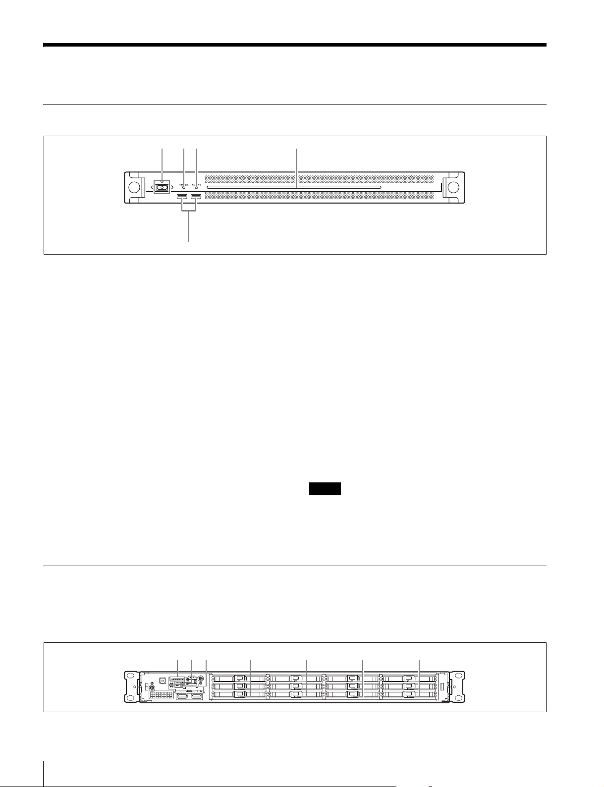
前面
123 4
5
a オン/スタンバイボタンおよびインジケーター
本機のオン /スタンバイを切り換えます。電源コードを接
続するとスタンバイ状態になり、インジケーターが赤色に
点灯します。スタンバイ状態のときにオン /スタンバイボ
タンを押すと、本機が起動してオン状態になり、インジ
ケーターが緑色に点灯します。オン状態のときにオン / ス
タンバイボタンを 2 秒以上長押しすると、スタンバイ状態
への移行を開始し、スタンバイ状態になるとインジケー
ターが赤色に点灯します。オン状態からスタンバイ状態に
した後、再度オンにする場合は、インジケーターが赤色に
点灯した後 3 秒以上たってからボタンを押してください。
電源コードが接続されていないときは、インジケーターが
消灯します。
b SYSTEM インジケーター
本機の状態を示します。
緑色点灯:正常動作中
緑色点滅(1秒周期):システム起動中またはスタンバイ移
行中
オレンジ色点滅(1秒周期):ワーニング発生
赤色高速点滅(1/4秒周期):エラー発生
c ACCESS インジケーター
ストレージへのアクセス状態を示します。
消灯:アクセスなし
青色点灯:アクセス中
d フロントパネル LED
Web メニューでの設定によって、点灯 / 消灯します。設定
は、メンテナンス画面の [Settings] ページ−[001:LINE
LED]で行います。
e USB 端子(前面)
本機の初期設定をする際に、キーボードやマウスを接続で
きます。
本書で説明されていない USB 機器については対応していま
せん。
ご注意
前面の USB 端子は、両ポートとも給電に対応しています
(900 mA)。
前面(パネルを外した場合)
SYSTEM インジケーターや Web メニューの表示でエラー
が通知された場合に、パネルを外してハードウェア各部の
ステータスを確認することができます。
123 4444
各部の名称と働き
10
パネルを外すには、前面パネル左右のネジをゆるめ、手前
に引きます。
a FAN インジケーター
ファンのいずれかに障害が発生した場合に、対応するイン
ジケーターが赤く点灯します。
b POWER インジケーター
AC 電源ユニットのどちらかに故障が検出された場合に、
対応するインジケーターが赤く点灯します。
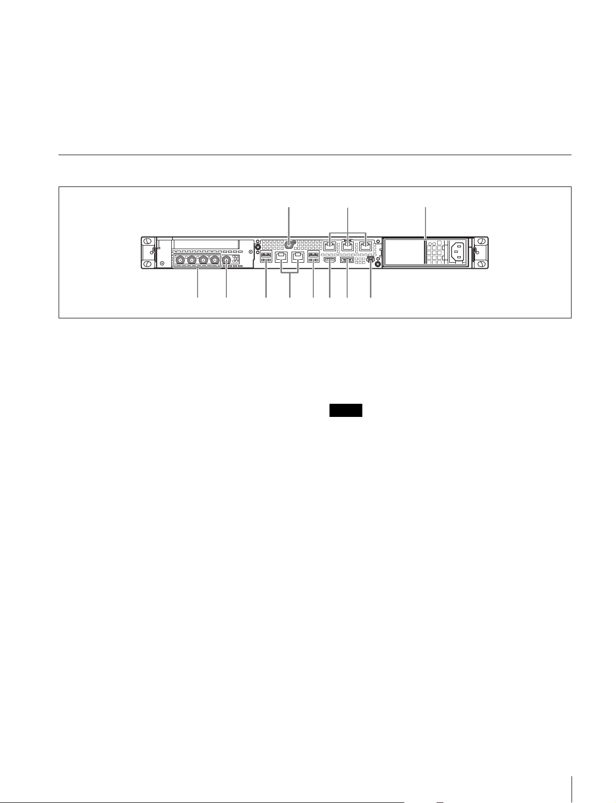
背面
c TEMP インジケーター
本機内部温度の異常上昇を検出した場合に赤く点灯します。
d HDD ステータスインジケーター
HDD にワーニングが発生した場合に赤く点灯します。該当
の HDD の故障を検出した場合、HDD がスリープ状態の場
合、HDD が存在しない場合は消灯します。
13
LAN1 LAN2
6768945 0
a SYSTEMTC 端子
本システムでは使用しません。
b Remote 端子(1/2、3/4、5)
Remote1/2、Remote3/4端子は、RJ-45−D-sub 変換ケーブ
ル(同梱)と市販の 9 ピンリモートケーブルを使用して VTR
機器と接続し、VTR機器のリモート操作を行います。RJ-45
−D-sub 変換ケーブル 1 本と 9 ピンリモートケーブル 2 本を
使用して、2台の VTRと接続することができます。
Remote5 端子は、本システムでは使用しません。
c AC 電源ユニット
電源コードを挿入して、電源コンセントに接続します。
工場出荷時は、AC電源ユニットが 1つ装着されています。
別売の電源ユニットを追加装着することによって、電源を
二重化することができます。信頼性が要求されるシステム
で本機を使用するとき、一方の電源ユニットが故障しても
運用の継続が可能です。
◆ 電源ユニットの追加または交換については、ソニーのサービス
担当者または営業担当者にご連絡ください。
d SDI(1 〜 4)端子
左から SDI1 端子〜 SDI4 端子の順になります。
SDI ケーブルで VTR 機器または外部モニターに接続し、
SDI 信号の入出力を行います。
2
112 3 4 5
f USB 端子(背面)
USB ケーブルでドライブユニットに接続します。
本書で説明されていない USB 機器については対応していま
せん。
ご注意
• 背面の 4 つの USB 端子のうち、右下のポートのみ給電に対応して
います(900mA)。他の 3 ポートは給電非対応ですので、USB
端子からの電力供給が不要な USB 機器を接続してください。
• ケーブルは、SuperSpeedUSB ケーブルをご使用ください。
g LAN 端子
ギガビットイーサネットに接続します。
h HDMI 端子
HDMI ケーブルでディスプレイに接続します。
HDMI ケーブルは、下記の規格に適合したケーブルをご使
用ください。
• HighSpeedHDMICable(PremiumHighSpeedHDMI
Cable)
i DisplayPort 端子
DisplayPort − DVI 変換ケーブルまたは DisplayPort −
HDMI 変換ケーブルでディスプレイに接続します。
変換ケーブルは、アクティブタイプのケーブルを使用して
ください。
e REFIN 端子
同期基準信号を入力します。
各部の名称と働き
11

ご注意
DisplayPort ケーブルは、下記の規格に適合したケーブルをご使用
ください。
• DPv1.2a(準拠)
準備
j アース端子
アースを接続します。
初期設定
本機を使用する前に、本機内の Windows の設定を行いま
す。設定方法については、標準的な Windows8 の操作方法
に準じます。
ご注意
本機を再起動する場合は、Windows の再起動ではなく、いったん
シャットダウンさせてから、前面のオン / スタンバイボタンを再
度オンにしてください。
1
前面の USB 端子にキーボードとマウスを接続し、背面
の DisplayPort 端子または HDMI 端子にディスプレイ
を接続する。
2
本体のオン / スタンバイボタンをオンにする。
3
Windows のログイン画面が表示されたら、ユーザー名
「tds」、パスワード「tds」でログインする。
Windows の表示言語を設定する
1
Windows ボタンを押しながら X キーを押し、表示され
るメニューから[ControlPanel]を選択する。
2
[Clock,Language,andRegion]の[Language]を選択
する。
3
言語を追加する場合は、[Addlanguage]を選択する。
4
追加する言語を選択し、[Add]をクリックする。
5
使用する言語を選択して[Moveup]をクリックし、
その言語がいちばん上に表示されるようにする。
6
いったんサインアウトしてからサインインする。
ネットワークを設定する
1
本機背面の LAN 端子に LAN ケーブルを接続し、ネット
ワークに接続する。
2
コントロールパネルの[NetworkandInternet]−
[Viewnetworkstatusandtasks]をクリックする。
12
準備
3
[Connections]の[LAN1/2]をクリックする。
4
[Properties]ボタンをクリックする。

5
[InternetProtocolVersion4(TCP/IPv4)]を選択して、
[Properties]ボタンをクリックする。
6
IP アドレスなどの設定を変更する。
7
DNS、WINS などの設定を行う場合は、[Advanced]
ボタンをクリックする。
8
設定が完了したら、[OK]ボタンをクリックする。
サービスのパスワードを設定する
ユーザー「tds」のパスワードを設定 / 変更したときは以下
のとおりサービスのパスワードを設定してください。
1
コントロールパネルから[SystemandSecurity]−
[Administrativetools]−[Services]を選択する。
2
サービスのリストで「ApacheTomcat7.0Tomcat7」
を右クリックし、[Properties]を選択する。
日時を設定する
1
コントロールパネルの[Clock,Language,andRegion]
で[DateandTime]−[Setthetimeanddate]を選
択する。
2
[DateandTime]タブの[Changetimezone]をク
リックして、タイムゾーンを選択する。
3
[DateandTime]タブの[Changedateandtime]を
クリックして、日付と時刻を設定する。
4
[InternetTime]タブの[Changesettings]ボタンを
クリックする。
5
NTP サーバーを設定し、[UpdateNow]ボタンをク
リックする。
6
定期的に NTP サーバーで時刻を補正する場合は、
[SynchronizewithanInternettimeserver]をチェッ
クする。
ユーザーのパスワードを設定する
3
[LogOn]タブを開く。
4
[ThisAccount]をクリックして「.¥tds」を入力し、
[Password]にユーザー「tds」のパスワードを入力す
る。
5
[Apply]ボタンをクリックし、[OK]をクリックして
ダイアログを閉じる。
6
サービスのリストで「SonyIngestService」を選択し、
手順 2 〜 5 の操作を行う。
ユーザーを追加する
Windows に新規ユーザーを追加します。
1
コントロールパネルの[UserAccountsandFamily
Safety]をクリックする。
2
[UserAccounts]の[Changeaccounttype]をクリッ
クする。
3
[AddanewuserinPCsettings]をクリックする。
本機内蔵の Windows には、工場出荷時にユーザー「tds」
が設定されています。セキュリティのため、このユーザー
のパスワードを設定してください。
1
コントロールパネルの[UserAccountsandFamily
Safety]をクリックする。
2
[UserAccount]の[Changeaccounttype]をクリッ
クする。
3
ユーザー「tds」を選択する。
4
[Changethepassword]をクリックする。
5
新しいパスワードとヒントを入力し、[Change
Password]ボタンをクリックする。
4
[Addauser]をクリックする。
5
ユーザー名、パスワード、ヒントを入力し、[Next]を
クリックする。
6
[Finish]をクリックする。
続けてアカウントタイプを変更します。
7
コントロールパネル−[UserAccountsandFamily
Safety]−[Changeaccounttype]をクリックする。
8
アカウントタイプを変更したいユーザーを選択する。
9
[Changetheaccounttype]をクリックする。
10
[Standard]または[Administrator]を選択して、
[Changeaccounttype]ボタンをクリックする。
準備
13

コンピューター名を変更する
PWS-100TD1 では、https 通信の認証の仕組みとしてコン
ピューター名を使用します。
コンピューター名を変更する場合は以下の手順で行ってく
ださい。新しい証明書が生成されます。
また、変更後はクライアント PC で新しい証明書を再取得
してください。
1
コントロールパネルから[SystemandSecurity]−
[System]を選択する。
2
[Computername]の[ChangeSettings]をクリック
する。
3
[SystemProperties]ダイアログの[Computername]
タブで[Change]ボタンをクリックする。
4
コンピューター名を変更して[OK]をクリックする。
5
再起動を要求されたら、コンピューターを再起動させ
る。
6
PWS-100TD1 本体に再度サインインする。
7
管理者権限のコマンドプロンプトを開き、以下のコマ
ンドを入力する。
>cdC:¥ProgramFiles¥Sony¥TapeDigitize¥DIG¥script
> keystore.bat
Web メニューの表示
本機の設定・操作は、クライアント PC からネットワーク
を介して本機に接続し、クライアント PC の Webブラウ
ザーに Webメニューを表示して行います。
クライアント PC の推奨環境
CPU:Corei53GHz 以上
メモリー:4 GB以上
OS: Windows7Pro32/64 ビット
Windows8/8.1Pro32/64 ビット
MacOSX10.8/10.9
Webブラウザー:GoogleChrome40 以上(最新のバージョ
ンにアップデートしてお使いください)
ディスプレイ:1366 × 768以上
上記推奨環境を備えたコンピューターを本機背面の LAN
端子 1または 2に接続します。コンピューターの Webブラ
ウザーのアドレス欄に「https://(IP アドレス):8443/tds
または https://pws-100- <シリアル番号> :8443/tds」
(「ネットワークを設定する」で設定した IP アドレス)と入
力して、Webメニューを表示させます。
ログイン画面が表示されたら、ユーザー名とパスワードを
入力してログインします。
工場出荷時は、下記のユーザー名とパスワードが設定され
ています。
ユーザー名:admin
パスワード:tds
8
システムを再起動する。
9
「証明書をインストールする」(15 ページ)の手順に
従って、証明書を再取得する。
サインアウトする
設定が完了したら、Windows からサインアウトします。
1
マウスカーソルを画面の右上に移動してチャームを表
示し、[Start]をクリックする。
2
画面右上のアカウント名をクリックし、[Signout]を
クリックする。
システム設定
Web メニューの設定画面で、本システムの設定を行いま
す。
Web メニューにログインする際は、管理者権限のあるユー
ザーでログインしてください。
なお、Web メニューでの操作について詳しくは、Web メ
ニューのヘルプをご覧ください。
表示言語の切り換え
Web メニューの表示言語を切り換えます。
設定は、設定画面の[個人設定]−[言語]で行います。
動作周波数の選択
本システムの動作周波数を選択します。設定は、設定画面
の[インジェスト]ページ−[インジェスト設定]で行い
ます。
14
準備

ユーザーの追加
9
メッセージが表示されたら、[OK]をクリックする。
デフォルトの admin 以外にオペレーターなどのアカウント
を追加するには、設定画面の[ユーザー]ページで新規
ユーザーを追加してください。
転送先の登録
作成したクリップを転送するカートリッジまたはネット
ワークサーバーは、設定画面の[転送]ページで登録しま
す。
証明書をインストールする
Web ブラウザーから https 接続で Web メニューを表示す
ると、「このサイトのセキュリティ証明書は信頼できませ
ん」などのエラーメッセージが出力されます。エラーなし
で https 接続を行うためには、サーバー(PWS-100- <シリ
アル番号>)に対応したルート CA 証明書(クライアント
証明書)を Web ブラウザーにインストールする必要があり
ます。
GoogleChrome で証明書をインストールする手順の例を以
下に示します。
ルート CA 証明書のインストール手順
1
Web ブラウザーで Web メニューに https 接続する。
「このサイトのセキュリティ証明書は信頼できません」
などのエラーメッセージが出力されます。
10
Chrome の設定ボタンをクリックし、メニューから[設
定]を選択する。
11
設定画面で[詳細設定を表示]をクリックし、
[HTTP/SSL]の下の[証明書の管理]ボタンをクリッ
クする。
[証明書]ダイアログが表示されます。
12
ダイアログの[信頼されたルート証明機関]タブをク
リックし、[インポート]ボタンをクリックする。
証明書をインポートするウィザードが表示されます。
13
[次へ]をクリックする。
14
[参照]ボタンをクリックしてダウンロードしたファイ
ルを選択し、[次へ]をクリックする。
15
[証明書をすべての次のストアに配置する]が選択され
ており、[証明書ストア]に「信頼されたルート証明機
関」と表示されていることを確認して、[次へ]をク
リックする。
証明書のインポートが始まります。
16
完了の画面が表示されたら、[完了]をクリックする。
ウィザードが終了します。
2
アドレスバーの左側にある鍵アイコンをクリックする。
3
ポップアップの[証明書情報]をクリックする。
[証明書]ダイアログが表示されます。発行元の
「PWS-100- <シリアル番号>」をメモしておきます。
4
[詳細]タブをクリックし、[ファイルにコピー]ボタ
ンをクリックする。
証明書をエクスポートするウィザードが表示されます。
5
[次へ]をクリックする。
6
「DERencodedbinaryX.509(.CER)」を選択し、[次へ]
をクリックする。
7
[参照]ボタンをクリックして証明書を保存するフォル
ダーを設定し、[次へ]をクリックする。
証明書のエクスポートが始まります。
8
完了の画面が表示されたら、[完了]をクリックする。
17
メッセージが表示されたら、[OK]をクリックする。
18
Chrome の設定ボタンをクリックして、メニューから
[終了]を選択する。その後、Chrome を再起動する。
19
「ネットワークを設定する」(12 ページ)で設定した IP
アドレスとメモした「PWS-100- <シリアル番号>」と
の名前解決を行い、https://pws-100- <シリアル番号>
:8443/tds で接続してください。
ライブラリ等のライセンスについて
PWS-100TD1 が使用する各種ライブラリ等のライセンスに
ついては、Web メニューの[ヘルプ]から確認できます。
メンテナンスアプリケーションの操作
システム管理者向けメンテナンスアプリケーション
(MaintenanceWebApplication)の操作については、本機
にログオンしてデスクトップ上にあるショートカットを開
いてマニュアルを参照してください。
準備
15

使用上のご注意
の寿命を保証するものではありません。交換の際はお買い
上げ店にご相談ください。
交換時期については、ソニーのサービス担当者または営業
担当者にご確認ください。
HDD内蔵機器に対する注意事項
本機には、ハードディスクドライブ(以下 HDDと称する)
が搭載されています。HDDは精密部品であり、衝撃・振
動・静電気・温度・湿度が原因で故障したり、HDD内の
データが破損する恐れがあります。本機を設置・使用する
ときは、以下の注意事項をよくお読みのうえ、慎重に取り
扱ってください。
衝撃・振動を与えない
衝撃・振動が加わると HDDが故障あるいは HDD内のデー
タが破損される恐れがあります。
• 本機を輸送する場合は、指定の梱包材料で梱包してくだ
さい。台車などで搬送する場合は、振動の少ない台車を
使用してください。過度な衝撃・振動が加わると HDD
が故障するおそれがあります。
• 通電中は本機を移動しないでください。
• 本機の外装を取り外さないでください。
• 本機を床などに置くときは、水平で安定した場所に置い
てください。
• 振動を発生する機器の近くには置かないでください。
• 本機を車載する場合、走行中は電源をオフにしてくださ
い。
電源オフ後 30秒間は作業しない
電源をオフにした後もしばらくの間は、HDD内のディスク
は慣性で回転しており、ヘッドは不安定な状態にあります。
この期間は、通電中以上に衝撃・振動に弱い状態です。電
源オフ後、最低 30 秒間は軽い衝撃も与えないようにご注意
ください。30 秒以上経過すれば、(ディスクが静止するの
で)作業を開始できます。
温度・湿度に関するご注意
適正範囲内の温度・湿度のある場所で、保管・使用してく
ださい。(仕様を守ってお使いください。)
HDDに不良症状が現れた場合
万一、本機の HDDが故障した(不良症状が現れた)と思
われる場合でも、本機の取り扱いは、上記と同様に行って
ください。不良内容の確認や不良解析を行うまでの損傷の
拡大を防ぎます。
電源に関する注意事項
本機が動作中に突然電源が切れた場合、データが壊れる可
能性があります。データ保護のため、UPS(無停電電源装
置)のご使用をお勧めします。
また、電源コードを抜く場合やブレーカーを落とす場合は、
必ず事前に本機のオン / スタンバイボタンを押して本機の
動作を停止させてください。
USB デバイスに関する注意事項
自給電タイプの USB デバイス(ODS-D77U など)を接続し
て使用する場合、デバイスの電源がオンになるタイミング
によっては、そのデバイスを認識できない場合があります。
その場合は USB デバイスの電源を入れ直すか、USB ケー
ブルを抜いて接続し直してください。
ネットワークに関する注意事項
使用環境によってはネットワーク上の意図せぬ第三者から
アクセスされる可能性があります。
セキュリティの面からすべてのパスワードを設定すること
を強く推奨します。
13 ページの手順に従って、すべてのパスワードを設定して
ください。
セキュリティの面から、製品をネットワークに接続してご
使用になる際は、ブラウザでコントロール画面にアクセス
し、アクセス制限設定を工場出荷時の設定値から変更して
設定することを強く推奨します。(14 ページ)
また、定期的にパスワードを変更することを推奨します。
設定作業中または設定作業後のブラウザで他のサイトを閲
覧しないでください。ブラウザにログインした状態が残り
ますので、意図しない第三者の使用や悪意のあるプログラ
ムの実行を防ぐために、設定作業が完了したら必ずブラウ
ザを終了してください。
HDDを含む有寿命部品の交換
HDD、バッテリーは有寿命部品として定期的な交換が必要
です。常温でのご使用の場合、2 〜 5 年を目安に交換する
ことを推奨します。ただし、交換時間は目安であり、部品
使用上のご注意
16
仕様
一般
電源 AC100V 〜240V
50/60Hz
消費電力 235W
待機電力 3W 以下
使用温度 5 ℃〜35 ℃
保存温度 −20 ℃〜+60 ℃
使用湿度 20%〜90%(相対湿度)
保存湿度 5%〜80%
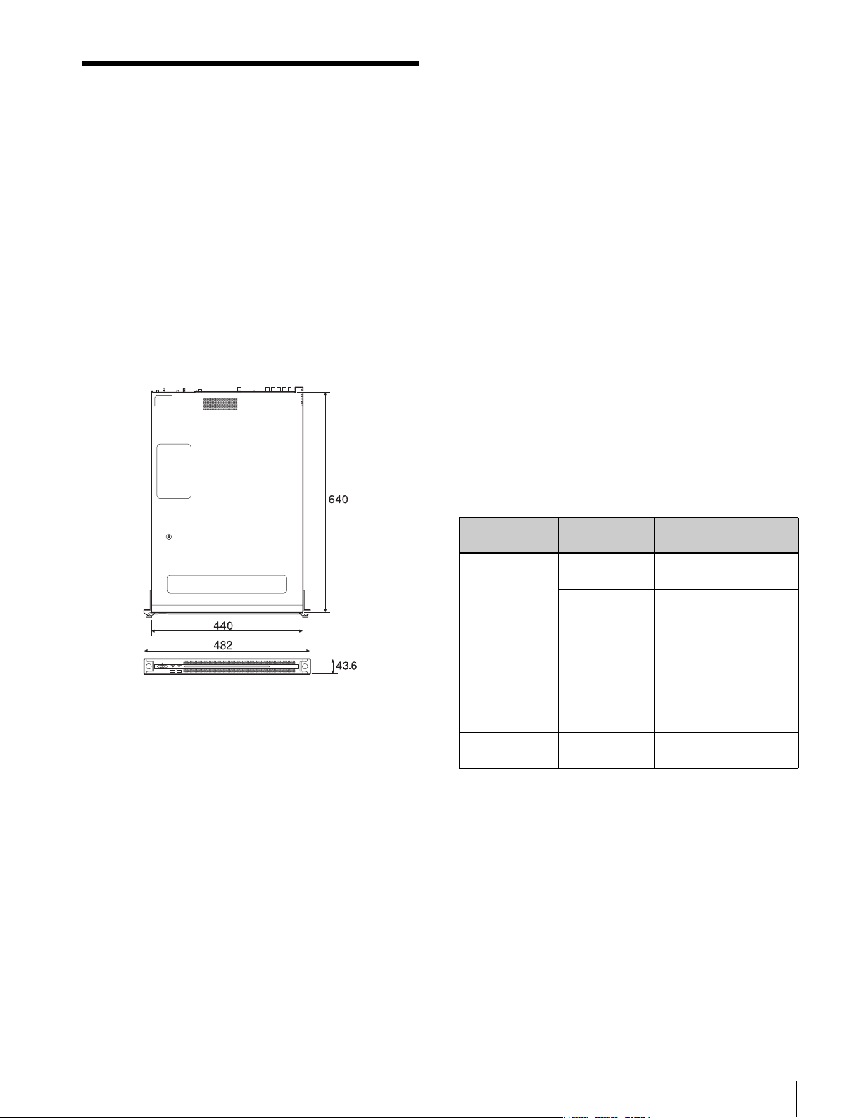
質量 14kg
外形寸法 440×43.6× 640mm(幅/高さ/奥行き)
背面:右下のポートのみ給電対応
(900 mA)、他 3 ポートは給電非対応
HDMI TypeA(1)
HDMIVer.1.4a、
最大解像度 1920 × 1200、60Hz
DisplayPort DisplayPort(1)
DisplayPortVer.1.1a、
最大解像度 2560 × 1600、60Hz
Remote RJ-45(3)
SonyVTRProtocol(9pin)対応、
RJ-45 − D-sub 変換ケーブル(同梱)
が必要です
REFIN BNC(1)
SMPTEST318 準拠 HD3値シンク
(0.6 Vp-p、75 Ω、同期正負)または
SDブラックバースト /コンポジット
シンク(NTSC:0.286Vp-p、75 Ω、
同期負
PAL:0.3Vp-p、75 Ω、同期負)
SDI1 〜 4 BNC(4)
HD:SMPTEST292-1準拠
SD:SMPTEST259準拠
CPU
プロセッサー IntelCorei76700TE(2.4GHz)
メモリ 8GBytes
SO-DIMM(DDR4)(2)
ドライブ(M.2) 120GBytes
ドライブ(HDD)
2.5 インチ、500GBytes、12 台
拡張バス PCIeGen28Lane(30W)(2)
入出力
LAN RJ-45(2)
1000BASE-T
100BASE-TX
USB(前面 / 背面)
SuperSpeedUSB(USB3.0)TypeA
(6、うち前面 2、背面 4)
前面:給電対応(各 900 mA)
対応フォーマット
コーデック 動作周波数 解像度量子化
ビット数
IMX
30M,40M,50M
UNCOMPRESS
220M
MPEGHD
50M
MPEGHD
35M
XAVC-I
100M
59.94i 720 × 576
4228bit
50i 720 × 480
4228bit
59.94i,50i,
29.97P,25P,23.98P
59.94i,50i,
29.97P,25P,23.98P
59.94i,50i,
29.97P,25P,23.98P
1920 × 1080
4228bit
1920 × 1080
4208bit
1440 × 1080
4208bit
1920 × 1080
42210bit
オーディオ
チャンネル
8ch(16bit)
4ch(24bit)
8ch(16bit)
4ch(24bit)
8ch(24bit)
4ch(16bit)
8ch(24bit)
仕様
17
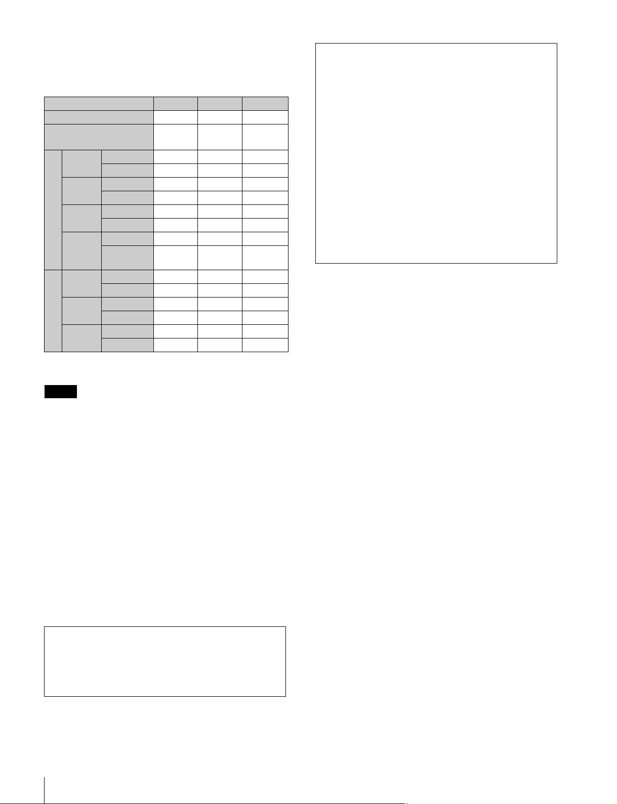
RAID 構成ごとの記録可能時間
RAID 構成およびビデオコーデックごとに記録できる時間
は次の通りです。
RAID 構成 2D + 1P 3D + 1P 5D + 1P
論理ドライブ数 4 3 2
30 Mbps
IMX
40 Mbps
IMX
50 Mbps
UNCOM
PRESS
220Mbps
35 Mbps
MPEG
50 Mbps
XAVC
100 Mbps
a)
1 ドライブ 約 50 時間 約 75 時間 約 125 時間
全ドライブ計 約 200 時間 約 225 時間 約 250 時間
1 ドライブ 約 35 時間 約 55 時間 約 95 時間
全ドライブ計 約 140 時間 約 165 時間 約 190 時間
1 ドライブ 約 30 時間 約 45 時間 約 70 時間
全ドライブ計 約 120 時間 約 135 時間 約 140 時間
1ドライブ 約7時間 約10時間 約18時間
全ドライブ計 約 28 時間 約 30 時間 約 36 時間
1 ドライブ 約 45 時間 約 70 時間 約 120 時間
全ドライブ計 約 180 時間 約 210 時間 約 240 時間
1 ドライブ 約 30 時間 約 45 時間 約 75 時間
全ドライブ計 約 120 時間 約 135 時間 約 150 時間
1 ドライブ 約 15 時間 約 25 時間 約 40 時間
全ドライブ計 約 60 時間 約 75 時間 約 80 時間
ドライブ容量
(1 論理ドライブあたり)
SD IMX
HD MPEG
a) GUI 上に表示される容量です。
838GB 1230GB 2050GB
• 必ず事前に記録テストを行い、正常に記録されている
ことを確認してください。本機や記録メディア、外部
ストレージなどを使用中、万一これらの不具合により
記録されなかった場合の記録内容の補償については、
ご容赦ください。
• お使いになる前に、必ず動作確認を行ってください。
故障その他に伴う営業上の機会損失等は保証期間中お
よび保証期間経過後にかかわらず、補償はいたしかね
ますのでご了承ください。
• 本製品を使用したことによるお客様、または第三者か
らのいかなる請求についても、当社は一切の責任を負
いかねます。
• 本機内、記録メディア、外部のストレージ等に記録さ
れたデータの損失、修復、複製の責任は負いかねます。
• 諸事情による本製品に関連するサービスの停止、中断
について、一切の責任を負いかねます。
• Windows は、米国 MicrosoftCorporation の米国およびそ
の他の国における登録商標または商標です。
• GoogleChrome は GoogleInc. の商標または登録商標です。
その他、本書に記載されているシステム名、製品名、会社
名は一般に各開発メーカーの登録商標または商標です。な
お、本文中では、®、™ マークは明記していません。
ご注意
記録素材の条件等により、記録時間が上記の記載と異なることが
あります。
付属品
RJ-45 − D-sub 変換ケーブル部品番号
1-848-424-12(SONY)(2)
別売アクセサリ
オプショナルパワーサプライPWSK-101
仕様および外観は、改良のため予告なく変更することがあ
りますが、ご了承ください。
通信を行う機器でセキュリティ対策を行わなかった結果、
または、通信仕様上の、やむを得ない事情により、デー
タ漏洩等、セキュリティ上の問題が発生した場合、弊社
ではそれによって生じたあらゆる損害に対する責任を負
いかねます。
本製品は、T-Engine フォーラム(www.t-engine.org)の
T-License2.0 に基づき T-Kernel2.0 ソースコードを利用して
います。
18
仕様
English
Table of Contents
Overview ............................................................................. 20
System Configuration Examples............................................ 21
Supported Devices............................................................. 26
Supported VTRs .................................................................... 26
Supported ODS Drives.......................................................... 26
Name and Function of Parts............................................... 27
Front View..............................................................................27
Front View (Panel Removed)................................................. 27
Rear View............................................................................... 28
Setting Up ........................................................................... 29
Initial Settings........................................................................ 29
Displaying the Web Application ........................................... 30
System Settings ..................................................................... 31
Installing Certificates ............................................................ 31
Library Licenses .................................................................... 32
Maintenance Web Application Operation............................. 32
Usage Precautions............................................................. 32
Specifications..................................................................... 33
GBGB
For safety, please read the precautions described in the PWS-100 Operation
Guide (supplied).
Table of Contents
19

Overview
The PWS-100TD1 is a system for digitizing VTR material
to create clips and for storing clips on cartridges in an
Optical Disc Archive System. It features the following
functions.
Ingest
The unit creates high-resolution video and proxy video
files from input SDI signals from one or more VTRs and
stores the ingested clips on internal HDDs. It can also
control VTR devices remotely using an RS-422 interface.
Video quality checking
The video quality of ingested clips can be checked
automatically. The video can also be checked visually by
an operator in the web application screen or on an external
monitor.
Clip storage
High-resolution clips can be transferred and stored on
cartridges or on a network server.
Workflows
A series of tasks, from ingesting through to transfer of
clips, can be executed in a single operation using
workflows. A manager can defines the workflow tasks to
execute and assign an operator to execute the tasks in a
work order, and the operator then executes the tasks
according to the work order.
Web application
Control and configuration of the unit is performed using a
graphical interface displayed in a web browser on a client
PC.
Integration with management software
The properties of clips stored on cartridges and proxy
video files can be exported and managed using other
software.
20
Overview
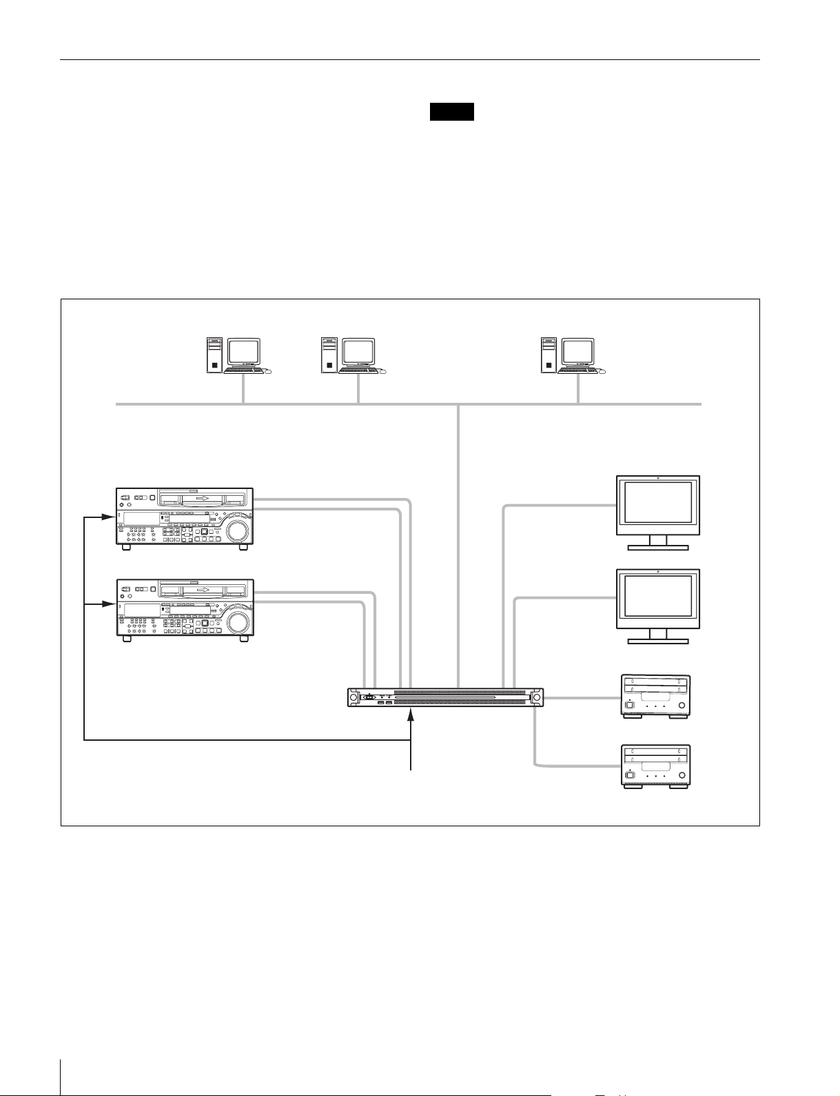
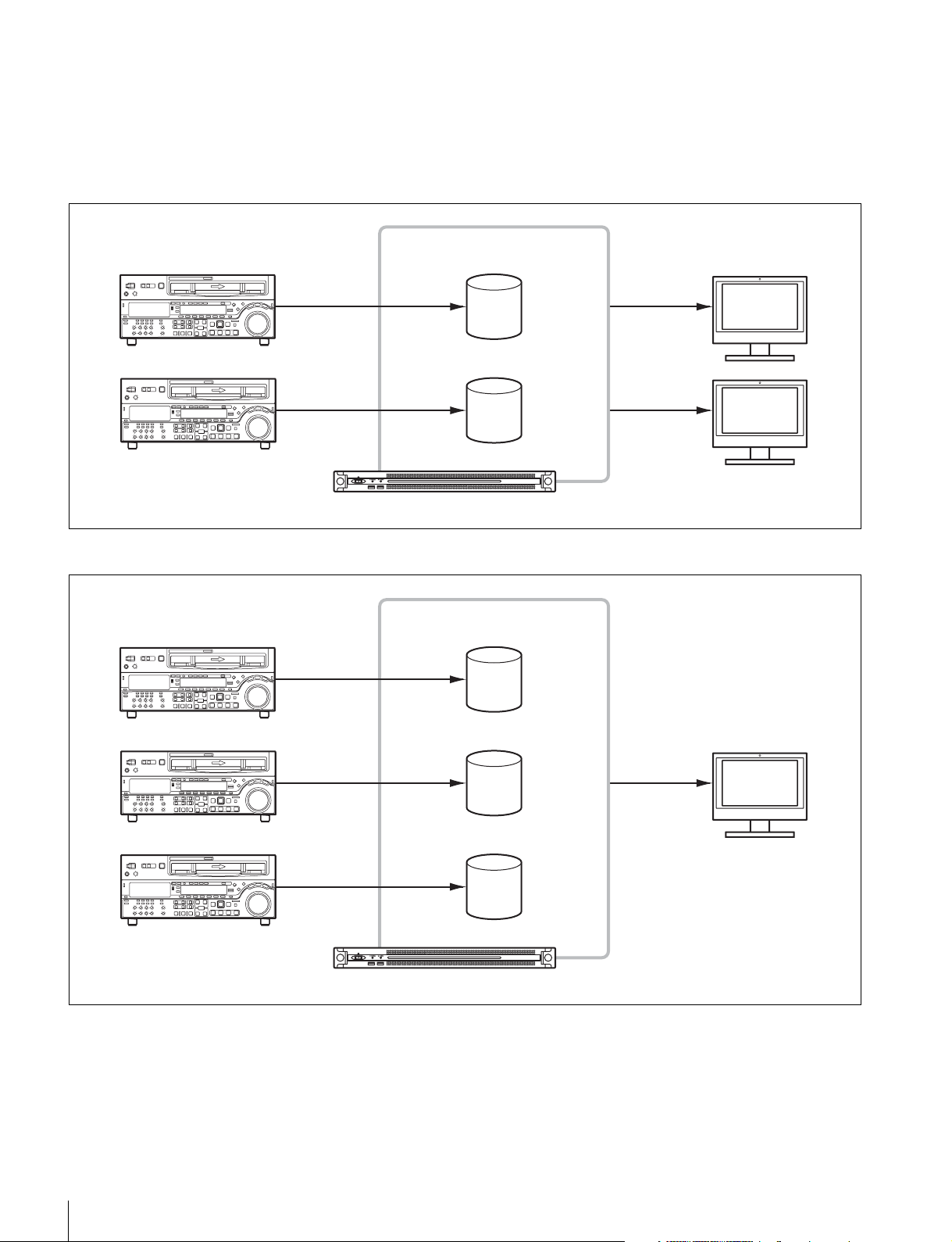
System Configuration Examples
Connect VTRs and external monitors to the SDI
connectors of the unit, and drive units to the USB
connectors on the rear panel. You can select a 2-input/
2-output, 3-input/1-output, or 4-input system
configuration by configuring SDI settings in the web
application.
2 inputs/2 outputs
Connect VTRs to the SDI 1 and SDI 2 connectors, and
external monitors to the SDI 3 and SDI 4 connectors. You
can use this configuration to digitize video from two VTRs
in parallel.
Operator Operator Manager
VTR
REF
HD/SD SDI
RS-422
Notes
• If multiple VTRs are connected, make sure that all VTRs are synchronized
(±1H).
• Set the EE/PB setting of the VTR to PB.
Gigabit Ethernet
External monitor
HD SDI
HD/SD SDI
RS-422
REF IN
Sync signal
HD SDI
USB 3.0
PWS-100TD1
USB 3.0
Drive unit
Overview
21

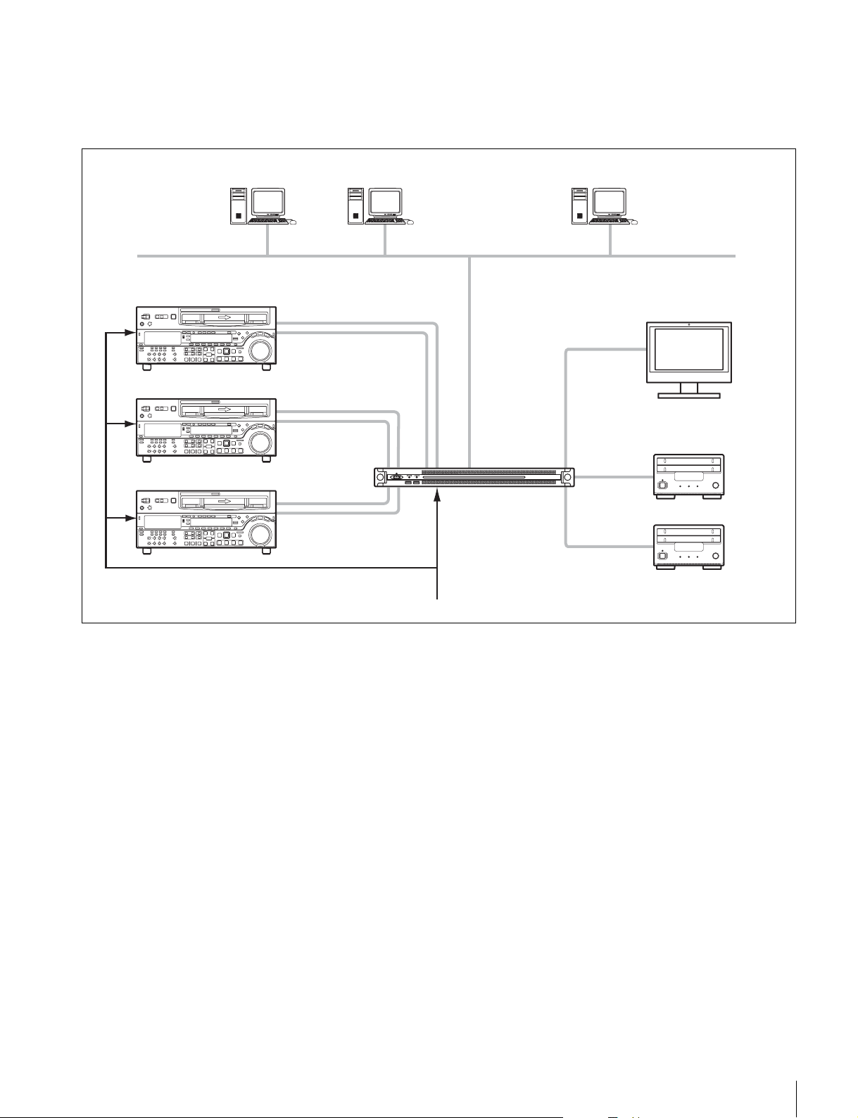
3 inputs/1 output
Connect VTRs to the SDI 1 to 3 connectors, and an
external monitor to the SDI 4 connector. The external
monitor connected to the SDI 4 connector is used to
monitor the high-resolution images of clips.
Operator Operator Manager
VTR
HD/SD SDI
REF
RS-422
HD/SD SDI
RS-422
Gigabit Ethernet
PWS-100TD1
External monitor
HD SDI
USB 3.0
HD/SD SDI
RS-422
REF IN
Sync signal
USB 3.0
Drive unit
22
Overview
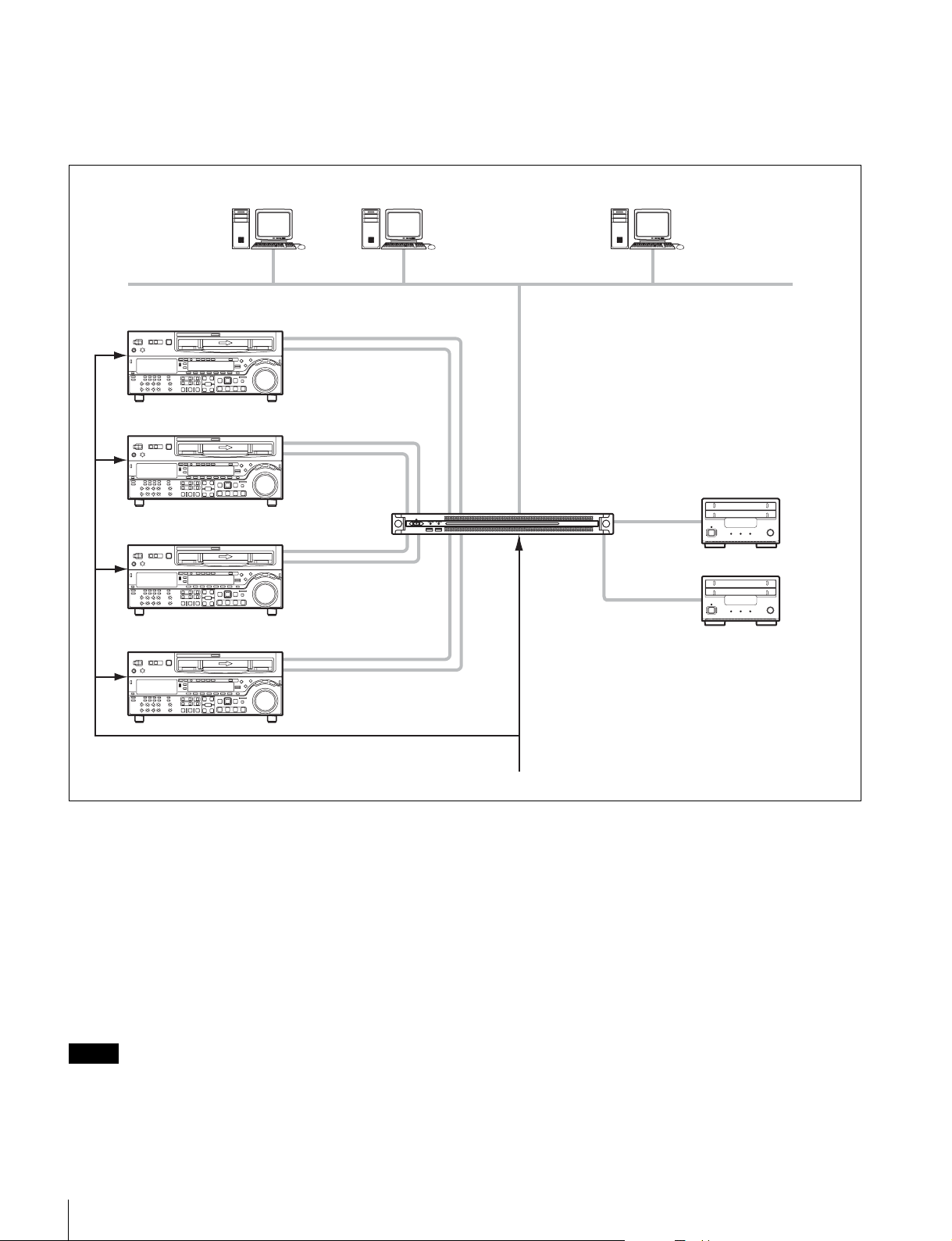
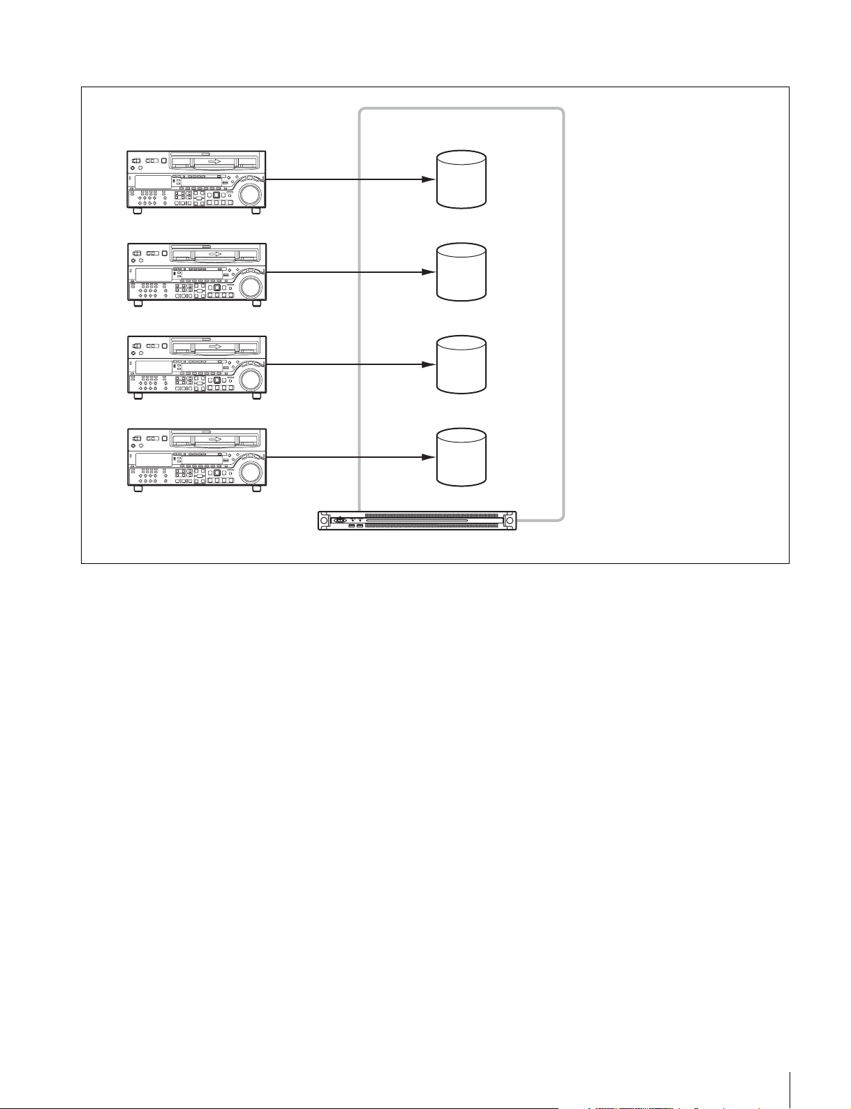
4 inputs
Connect VTRs to the SDI 1 to 4 connectors. When SDI4 is
not used for ingesting, you can monitor the high-resolution
images of clips in the GUI.
Operator Operator Manager
VTR
REF
HD/SD SDI
RS-422
HD/SD SDI
RS-422
Gigabit Ethernet
HD/SD SDI
RS-422
HD/SD SDI
RS-422
PWS-100TD1
REF IN
Sync signal
USB 3.0
USB 3.0
Drive unit
RAID configuration selection
After setting the system configuration, set the RAID configuration so that it has the same number SDI inputs and logical
drives as the selected system configuration.
You set the RAID configuration using the PWS-100 maintenance web application. Set up the RAID configuration shown
below, according to the selected system configuration. Configurations other than the following are not supported.
For details about configuration, refer to the operation manual of the PWS-100 maintenance web application.
• For 2 inputs/2 outputs: (5D + 1P) × 2
• For 3 inputs/1 output: (3D + 1P) × 3
• For 4 inputs: (2D + 1P) × 4
Note
If the RAID configuration is changed, all full-resolution files, proxy files, report files, and work orders written in internal storage are deleted.
Before changing the RAID configuration, always transfer or download all data to prevent data loss.
Overview
23
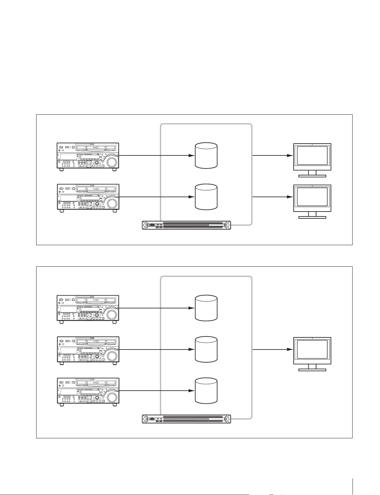
About RAID configuration
The PWS-100TD1 supports the following RAID configurations when a total of 12 HDDs are installed.
• 2D + 1P: Contains a total of four logical drives, where each logical drive contains two data HDDs and one parity HDD.
• 3D + 1P: Contains a total of three logical drives, where each logical drive contains three data HDDs and one parity HDD.
• 5D + 1P: Contains a total of two logical drives, where each logical drive contains five data HDDs and one parity HDD.
For 2 inputs/2 outputs
Logical drives (5D+1P)
External monitorVTR
For 3 inputs/1 output
VTR
SDI input
SDI input
SDI input
SDI output
SDI output
PWS-100TD1
Logical drives (3D+1P)
External monitor
24
SDI input SDI output
SDI input
PWS-100TD1
Overview
For 4 inputs
VTR
Logical drives (2D+1P)
SDI input
SDI input
SDI input
SDI input
PWS-100TD1
Overview
25

Supported Devices
Operation with the following devices has been certified.
Supported VTRs
Operation with the following VTRs has been certified.
Betacam SP BVW-75
Digital Betacam DVW-A500
Betacam SX DNW-A75
IMX MSW-M2000
DVCAM DSR-2000
HDCAM HDW-M2000
BVW-75P
DVW-A500P
DNW-A75P
MSW-M2000P
DSR-2000P
HDW-M2000P
Supported ODS Drives
Operation with the following ODS drives has been
certified.
• ODS-D55U
• ODS-D77U
• ODS-D280U
26
Supported Devices

Name and Function of Parts
Front View
123 4
5
a On/Standby button and indicator
Switches the unit on/off (standby state). Connecting the
power cord places the unit in standby state, and the
indicator turns on red. Pressing the On/Standby button
while in standby state turns on the unit and the indicator
turns on green. Pressing and holding the On/Standby
button for two seconds switches the unit to standby state,
and the indicator changes to red. To turn the unit on again
after switching from On state to standby state, when the
indicator is red, press and hold the On/Standby button for
three seconds or longer. The indicator goes out when the
power cord is disconnected.
b SYSTEM indicator
Indicates the status of the unit.
Green: Operating normally
Flashing green (once per second): System is booting or
transitioning to standby state.
Flashing orange (once per second): A warning has been
generated.
Front View (Panel Removed)
High-speed flashing red (four times per second): An
error has occurred.
c ACCESS indicator
Indicates the access status to storage.
Off: Not accessing storage
Blue: Accessing storage
d Front panel LED
Turns on according to settings in the web application. The
LED is configured using [001: LINE LED] in the
[Settings] page on the Maintenance screen.
e USB connectors (front panel)
Connects to a keyboard and mouse for initializing the unit.
USB devices not described in this document are not supported.
Note
Both USB ports on the front panel support power delivery (900 mA).
When the SYSTEM indicator or web application indicates
an error, you can remove the front panel to check the status
of the hardware components.
123 4444
a FAN indicators
If any of the fans fail, the corresponding fan indicator turns
on red.
To remove the front panel, loosen the screws on the left
and right sides and pull the panel towards you.
b POWER indicators
If either of the AC power supply units fail, the
corresponding indicator turns on red.
Name and Function of Parts
27
c TEMP indicator
If an abnormally high temperature is detected within the
unit, the indicator turns on red.
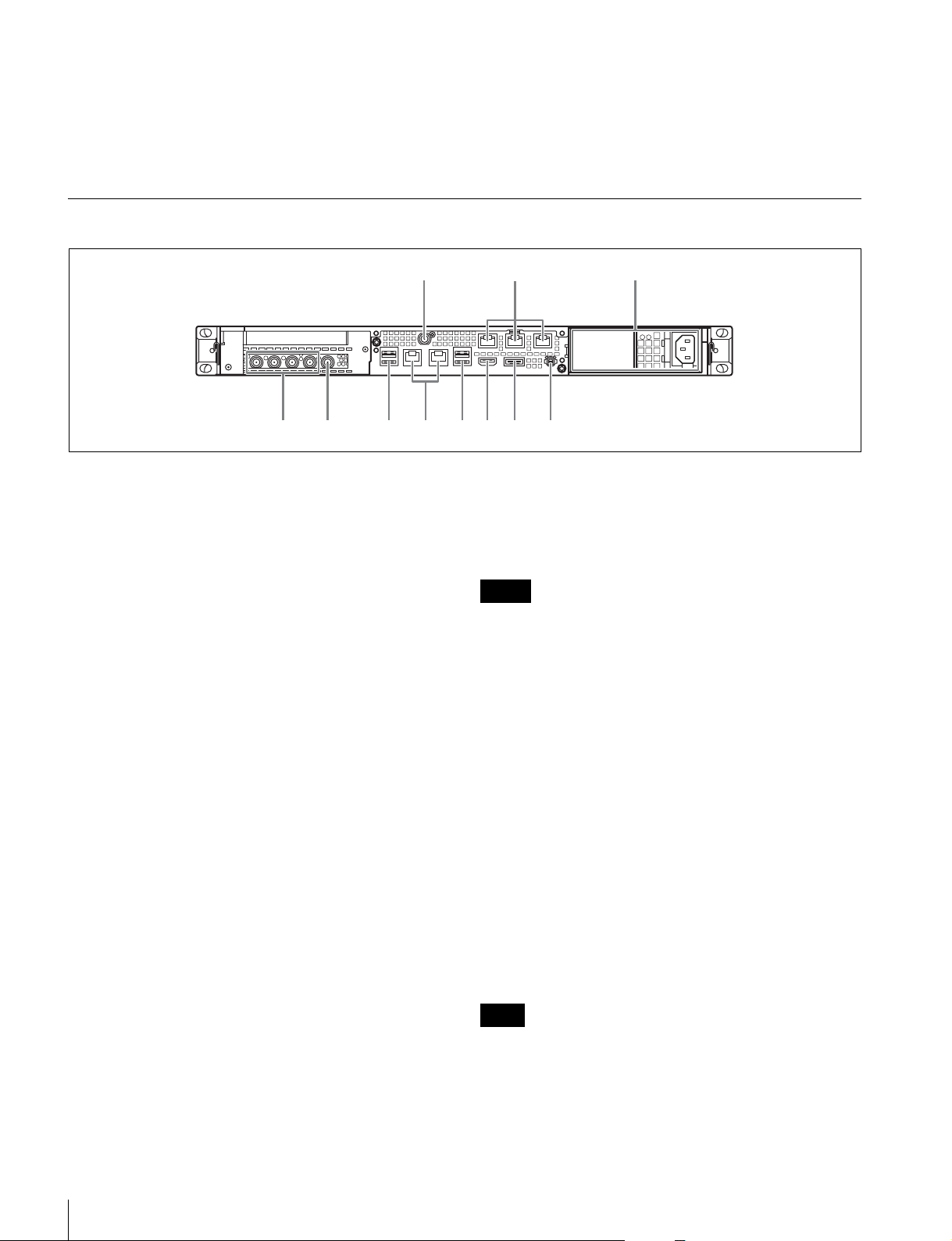
Rear View
d HDD status indicators
If a warning is generated for an HDD, the corresponding
indicator turns on red. The indicator turns off if the
corresponding HDD fails, is in sleep state, or has been
removed.
1
LAN1 LAN2
6768945 0
a SYSTEM TC connector
Not used by this system.
b Remote connectors (1/2, 3/4, 5)
Connect VTR devices to the Remote 1/2 and Remote 3/4
connectors, using the RJ-45 D-sub conversion cable
(supplied) and commercially-available 9-pin remote
cables, for VTR remote control operation. You can
connect two VTRs using a single RJ-45 D-sub conversion
cable and two 9-pin remote cables.
The Remote 5 connector is not used by this system.
c AC power supply units
Insert the power cords and connect to power outlets.
Only one AC power supply unit is installed at the factory.
A second optional power supply unit can be installed to
provide power supply redundancy. When used in systems
that require reliability, power supply redundancy allows
the unit to continue operating even if a power supply unit
fails.
23
112 3 4 5
f USB connectors (rear panel)
Connect to drive units using USB cables.
USB devices not described in this document are not
supported.
Notes
• Of the four USB connectors on the rear panel, only the bottom right port
supports power delivery (900 mA). The other three ports do not support
power delivery, and should be used to connect USB devices that do not
require power supplied from the USB connector.
• Use SuperSpeed USB cables.
g LAN connectors
Connect to a Gigabit Ethernet network.
h HDMI connector
Connect to a monitor using an HDMI cable.
Use an HDMI cable that conforms to the following
standard.
• High Speed HDMI Cable (Premium High Speed HDMI
Cable)
For details about installing or replacing a power supply
unit, consult your Sony sales or service representative.
d SDI (1 to 4) connectors
SDI1 to SDI4 connectors are numbered from left to right.
Connect to a VTR device or external monitor, using an
SDI cable, to input/output SDI signals.
e REF IN connector
Input a sync reference signal.
28
Name and Function of Parts
i DisplayPort connector
Connect to a monitor using a DisplayPort-to-DVI
converter cable or DisplayPort-to-HDMI converter cable.
Use an active-type converter cable.
Note
Use a DisplayPort cable that conforms to the following standard.
• DP v1.2a (compliant)
j Ground terminal
Connect to ground.

Setting Up
5
Select [Internet Protocol Version 4 (TCP/IPv4)], then
click the [Properties] button.
6
Change the IP address and other settings.
Initial Settings
Before using the unit, configure the Windows settings
within the unit. The description below describes the
standard settings in Windows 8.
Note
To reboot the unit, first shut down the unit and then turn the On/Standby
button on the front panel on again, without rebooting Windows.
1
Connect a keyboard and mouse to the USB connectors
on the front panel, and connect a monitor to the
DisplayPort connector or HDMI connector on the rear
panel.
2
Set the On/Standby button to the On position.
3
When the Windows login screen appears, enter “tds”
as the user name, enter “tds” as the password, and log
in.
Setting the Windows interface language
1
Hold down the Windows key and press the X key, then
select [Control Panel] from the displayed menu.
7
Click the [Advanced] button to configure DNS,
WINS, and other settings.
8
When finished, click the [OK] button.
Setting the date and time
1
Select [Set the time and date] under [Date and Time]
in the [Clock, Language, and Region] control panel.
2
Click [Change time zone] on the [Date and Time] tab,
and select the time zone.
3
Click [Change date and time] on the [Date and Time]
tab, and set the date and time.
4
Click the [Change settings] button on the [Internet
Time] tab.
5
Specify an NTP server, then click the [Update Now]
button.
6
Place a check mark in [Synchronize with an Internet
time server] to periodically correct the clock using the
NTP server.
2
Select [Clock, Language, and Region] > [Language].
3
Select [Add language] to add a language.
4
Select the language to add, then click [Add].
5
Select the language to use and click [Move up] until
the language is displayed at the top.
6
Sign out and then sign in again.
Configuring the network
1
Connect a LAN cable to the LAN connector on the rear
panel of the unit, and connect the other end to the
network.
2
Click [View network status and tasks] under [Network
and Internet] in the control panel.
3
Click [Connections] > [LAN 1/2].
4
Click the [Properties] button.
Setting user passwords
The default user “tds” is configured for Windows within
the unit. Set the password for the user to provide security.
1
Click [User Accounts and Family Safety] in the
control panel.
2
Click [User Account] > [Change account type].
3
Select the “tds” user.
4
Click [Change the password].
5
Enter a new password and a password hint, then click
the [Change Password] button.
Setting the service password
When setting/modifying the “tds” user password, set the
service password as follows.
1
Double-click [Services] under [Administrative tools]
in the [System and Security] control panel.
Setting Up
29

2
Right-click “Apache Tomcat 7.0 Tomcat7” in the
Services list and select [Properties].
3
Open the [Log On] tab.
4
Click [This account], enter “.\tds” and then enter a
password for user “tds” under [Password].
5
Click the [Apply] button, then click [OK] to close the
dialog.
6
Select “Sony Ingest Service” in the Services list, and
repeats steps 2 to 5.
2
Click [Computer name] > [Change Settings].
3
Click the [Change] button on the [Computer name] tab
of the [System Properties] dialog.
4
Change the computer name, then click [OK].
5
Restart the computer when prompted to restart.
6
Sign in to the PWS-100TD1 unit again.
7
Open Command Prompt as an administrator, and enter
the following commands.
Adding a user
You can add new users to Windows.
1
Click [User Accounts and Family Safety] in the
control panel.
2
Click [User Accounts] > [Change account type].
3
Click [Add a new user in PC settings].
4
Click [Add a user].
5
Enter a user name, password, and password hint, then
click [Next].
6
Click [Finish].
Next, change the account type.
7
Click [Change account type] under [User Accounts
and Family Safety] in the control panel.
8
Select the user whose account type you want to
change.
9
Click [Change the account type].
10
Select [Standard] or [Administrator], then click the
[Change account type] button.
Changing the computer name
The PWS-100TD1 uses the computer name as part of the
https communications authentication.
To change the computer name, use the following
procedure. A new certificate will be generated.
After the computer name is changed, re-import the new
certificate on the client PC.
1
Select [System and Security] > [System] in [Control
Panel].
> cd C:\Program Files\Sony\TapeDigitize\DIG\script
> keystore.bat
8
Restart the system.
9
Re-import the certificate as described in “Installing
Certificates” (page 31).
Signing out
When finished, sign out from Windows.
1
Move the mouse cursor to the top right corner of the
screen to display the Charms bar, then click [Start].
2
Click the account name on the top right of the screen,
then click [Sign out].
Displaying the Web Application
You connect to the unit via the network from a client PC
and use the web application in a web browser on the client
PC to control and configure the unit.
Recommended client PC environment
CPU: Core i5 3 GHz or higher
Memory: 4 GB or higher
OS: Windows 7 Pro 32/64-bit
Windows 8/8.1 Pro 32/64-bit
Mac OS X 10.8/10.9
Web browser: Google Chrome 40 or later (update to the
latest version)
Display resolution: 1366 × 768 pixels or higher
Connect a computer satisfying the above conditions to the
LAN 1 or LAN 2 connector on the rear panel of the unit.
Enter “https://(IP_address):8443/tds or https://pws-100<serial_number>:8443/tds” in the address bar of a web
browser on the computer (where IP_address is the address
specified in “Configuring the network”) to display the
web application.
30
Setting Up
 Loading...