

Sony PWS-100MG1 Operation Manual

MEDIA GATEWAY STATION
PWS-100MG1
電気製品は、安全のための注意事項を守らないと、火災や人
身事故になることがあります。
このオペレーションマニュアルには、事故を防ぐための重要な注意事項と製品
の取り扱いかたを示してあります。このオペレーションマニュアルをよくお読
みのうえ、製品を安全にお使いください。お読みになったあとは、いつでも見
られるところに必ず保管してください。
OPERATION MANUAL
[Japanese/English/French/German/Italian/Spanish/Chinese/Korean]
1st Edition (Revised 2)
日本語
目次
概要 .................................................................................................................................. 3
システム構成と接続..................................................................................................................................3
対応機器...........................................................................................................................3
対応ドライブ..................................................................................................................................................3
対応 NIC ............................................................................................................................................................3
各部の名称と働き ........................................................................................................... 4
前面 .......................................................................................................................................................................4
前面(パネルをはずした場合).........................................................................................................4
背面 .......................................................................................................................................................................5
準備 .................................................................................................................................. 6
初期設定.............................................................................................................................................................6
アプリケーションの起動と終了....................................................................................................... 6
アプリケーションの設定....................................................................................................................... 7
システムの設定 ............................................................................................................................................ 7
メンテナンスアプリケーションの操作 ........................................................................ 7
使用上のご注意 ............................................................................................................... 8
仕様 .................................................................................................................................. 9
安全のためのご注意が PWS-100 オペレーションガイド(付属)に記載されてい
ますので、ご使用の前にお読みください。
目次
2

概要
対応機器
本機は、メディアゲートウェイソフトウェア PWA-MGW1
を使用して、4K-Live システムでサーバーに収録された
ファイルをメディアにアーカイブしたり、メディアに格納
したファイルをサーバーにリトリーブするシステムです。
オプティカルディスクアーカイブカートリッジ、プロ
フェッショナルディスク、SxS メモリーカード、および
ハードディスクドライブをメディアとして使用できます。
◆ 操作について詳しくは、PWA-MGW1 のヘルプを参照してくだ
さい。
システム構成と接続
サーバーと本機をイーサネットで接続し、本機の USB 端子
にドライブユニットを接続します。
お客様へのお願い
本機のインストールは、ソニーのサービス担当者または
サービストレーニングを受けた技術者にご依頼ください。
本機が動作を確認している機器を次に示します。
対応ドライブ
下記のドライブとの動作を確認しています。
ODS ドライブ
• ODS-D55U
• ODS-D77U
プロフェッショナルディスクドライブ
• PDW-U1
• PDW-U2
SxS メモリーカード USB リーダーライター
• SBAC-US10
• SBAC-US20
• SBAC-US30
対応 NIC
JP
下記の 10GbE ネットワークカードとの動作を確認してい
ます。
IntelEthernetConvergedNetworkAdapterX520-DA1
概要/対応機器
3
各部の名称と働き
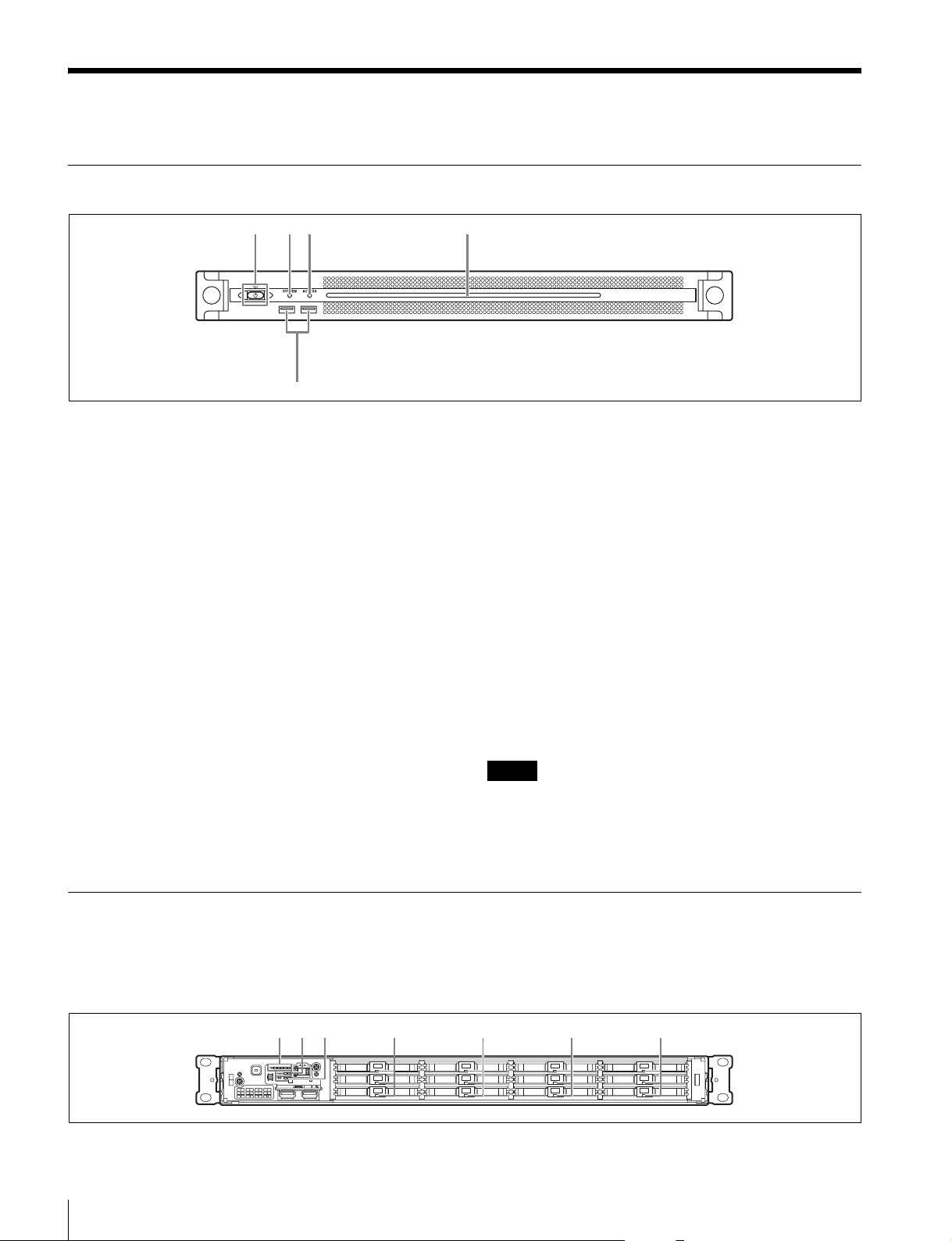
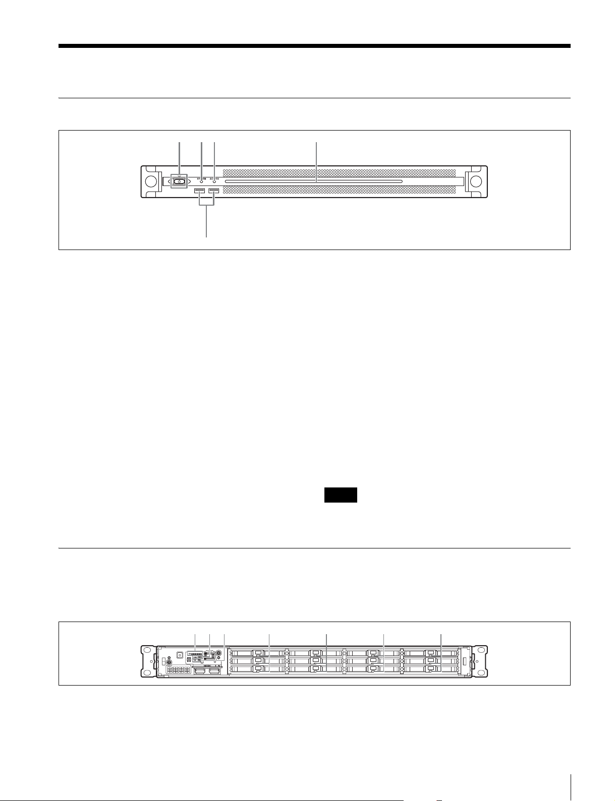
前面
123 4
5
a オン/スタンバイボタンおよびインジケーター
本機のオン /スタンバイを切り換えます。電源コードを接
続するとスタンバイ状態になり、インジケーターが赤色に
点灯します。スタンバイ状態のときにオン /スタンバイボ
タンを押すと、本機が起動してオン状態になり、インジ
ケーターが緑色に点灯します。オン状態のときにオン / ス
タンバイボタンを 2 秒以上長押しすると、スタンバイ状態
への移行を開始し、スタンバイ状態になるとインジケー
ターが赤色に点灯します。オン状態からスタンバイ状態に
した後、再度オンにする場合は、インジケーターが赤色に
点灯した後 3 秒以上たってからボタンを押してください。
電源コードが接続されていないときは、インジケーターが
消灯します。
b SYSTEM インジケーター
本機の状態を示します。
緑色点灯:正常動作中
緑色点滅(1秒周期):システム起動中またはスタンバイ移
行中
オレンジ色点滅(1秒周期):ワーニング発生
赤色高速点滅(1/4秒周期):エラー発生
c ACCESS インジケーター
ストレージへのアクセス状態を示します。
消灯:アクセスなし
青色点灯:アクセス中
d フロントパネル LED
Web メニューでの設定によって、点灯 / 消灯します。設定
は、メンテナンス画面の [Settings] ページ−[001:LINE
LED]で行います。
e USB 端子(前面)
本機の初期設定をする際に、キーボードやマウスを接続で
きます。
本書で説明されていない USB 機器については対応していま
せん。
ご注意
• 前面の USB 端子は、両ポートとも給電に対応しています
(900 mA)。
• ケーブルは、SuperSpeedUSB ケーブルをご使用ください。
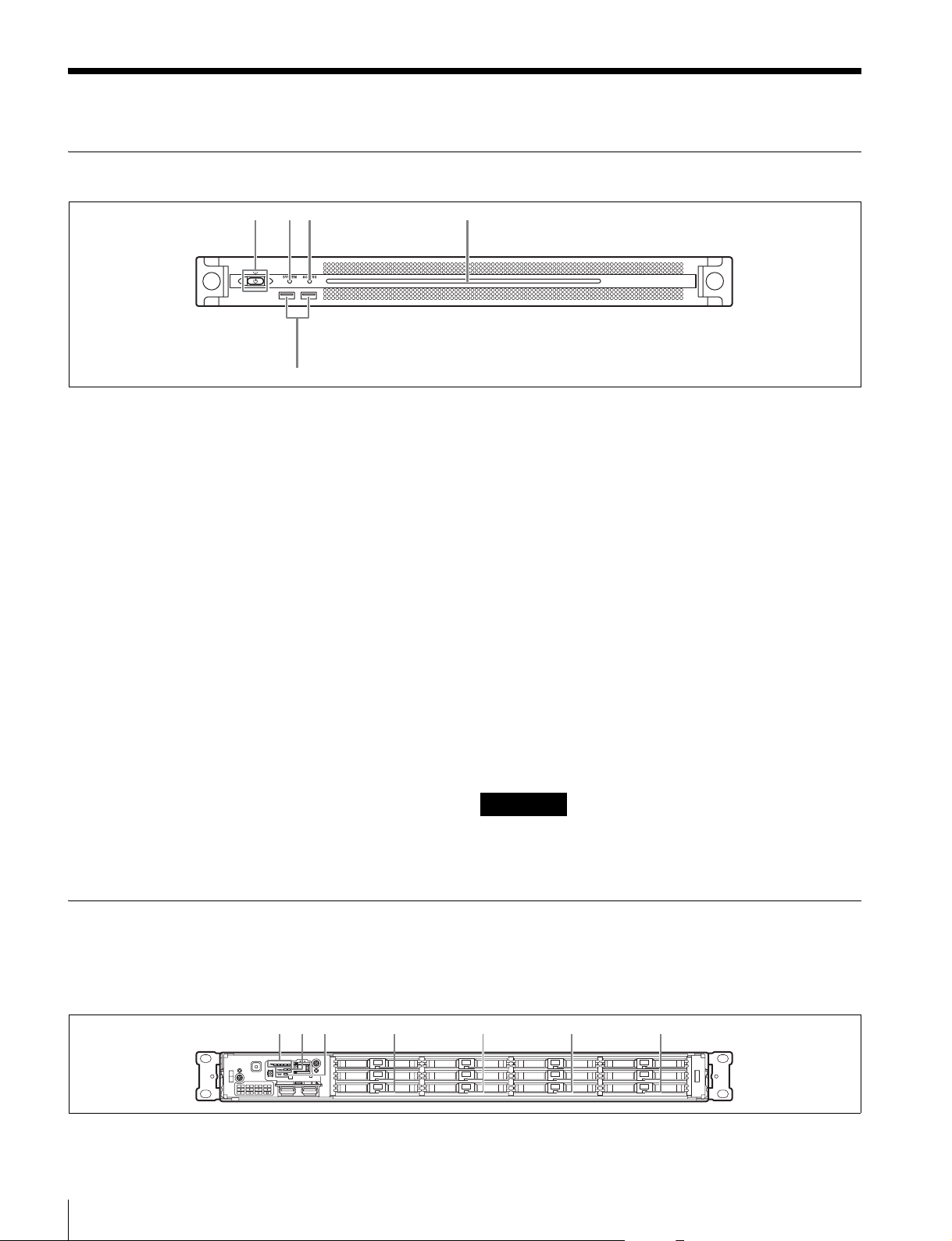
前面(パネルをはずした場合)
SYSTEM インジケーターや Web メニューの表示でエラー
が通知された場合に、パネルをはずしてハードウェア各部
のステータスを確認することができます。
123 4444
各部の名称と働き
4
パネルをはずすには、前面パネル左右のネジをゆるめ、手
前に引きます。

a FAN インジケーター
ファンのいずれかに障害が発生した場合に、対応するイン
ジケーターが赤く点灯します。
b POWER インジケーター
AC 電源ユニットのどちらかに故障が検出された場合に、
対応するインジケーターが赤く点灯します。
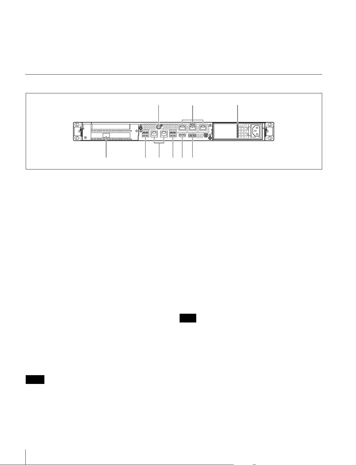
背面
112 3
LAN1 LAN2
565784
c TEMP インジケーター
本機内部温度の異常上昇を検出した場合に赤く点灯します。
d HDD ステータスインジケーター
HDD にワーニングが発生した場合に赤く点灯します。該当
の HDD の故障を検出した場合、HDD がスリープ状態の場
合、HDD が存在しない場合は消灯します。
112 34 5
a SYSTEMTC 端子
本システムでは使用しません。
b Remote 端子(1/2、3/4、5)
本システムでは使用しません。
c AC 電源ユニット
電源コードを挿入して、電源コンセントに接続します。
工場出荷時は、AC電源ユニットが 1つ装着されています。
別売の電源ユニットを追加装着することによって、電源を
二重化することができます。信頼性が要求されるシステム
で本機を使用するとき、一方の電源ユニットが故障しても
運用の継続が可能です。
◆ 電源ユニットの追加または交換については、ソニーのサービス
担当者または営業担当者にご連絡ください。
d SFP+ スロット
SFP+ モジュールを装着します。
e USB 端子(背面)
USB ケーブルでドライブユニットに接続します。
本書で説明されていない USB 機器については対応していま
せん。
f LAN 端子
ギガビットイーサネットに接続します。
g HDMI 端子
HDMI ケーブルでディスプレイに接続します。
HDMI ケーブルは、ソニー製ケーブルをご使用ください。
推奨ケーブル(例):HIGHSPEEDHDMI ケーブル
DLC-HE20XF(2 m)
h DisplayPort 端子
DisplayPort ケーブルでディスプレイに接続します。
下記の推奨ケーブルをご使用ください。
• LINDY 社製型番 416304K 対応DisplayPort ケーブル
(1 m)
ディスプレイについては下記機種で動作を確認済みです。
• ASUS 社:PB248Q
ご注意
DisplayPort − DVI 変換ケーブルまたは DisplayPort − HDMI 変
換ケーブルをご使用の場合は、アクティブタイプのケーブルを使
用してください。
ご注意
• 背面の 4 つの USB 端子のうち、右下のポートのみ給電に対応して
います(900mA)。他の 3 ポートは給電非対応ですので、USB
端子からの電力供給が不要な USB 機器を接続してください。
• ケーブルは、SuperSpeedUSB ケーブルをご使用ください。
各部の名称と働き
5

日時を設定する
準備
初期設定
本機を使用する前に、本機内の Windows の設定を行いま
す。設定方法については、標準的な Windows8 の操作方法
に準じます。
ご注意
本機を再起動する場合は、Windows の再起動ではなく、いったん
シャットダウンさせてから、前面のオン / スタンバイボタンを再
度オンにしてください。
1
前面の USB 端子にキーボードとマウスを接続し、背面
の DisplayPort 端子または HDMI 端子にディスプレイ
を接続する。
2
本体のオン / スタンバイボタンをオンにする。
3
Windows のログイン画面が表示されたら、ユーザー名
には「mgw」パスワードには「mgw」と入力し、ログ
インする。
1
コントロールパネルの[Clock,Language,andRegion]
で[DateandTime]−[Setthetimeanddate]を選
択する。
2
[DateandTime]タブの[Changetimezone]をク
リックして、タイムゾーンを選択する。
3
[DateandTime]タブの[Changedateandtime]を
クリックして、日付と時刻を設定する。
4
[InternetTime]タブの[Changesettings]ボタンを
クリックする。
5
NTP サーバーを設定し、[UpdateNow]ボタンをク
リックする。
6
定期的に NTP サーバーで時刻を補正する場合は、
[SynchronizewithanInternettimeserver]をチェッ
クする。
サインアウトする
設定が完了したら、Windows からサインアウトします。
ネットワークを設定する
1
本機背面の LAN 端子に LAN ケーブルを接続し、ネット
ワークに接続する。
2
コントロールパネルの[NetworkandInternet]−
[Viewnetworkstatusandtasks]をクリックする。
3
[Connections]で LAN ケーブルを接続しているデバイ
スをクリックする。
4
[Properties]ボタンをクリックする。
5
[InternetProtocolVersion4(TCP/IPv4)]を選択して、
[Properties]ボタンをクリックする。
6
IP アドレスなどの設定を変更する。
7
DNS、WINS などの設定を行う場合は、[Advanced]
ボタンをクリックする。
8
設定が完了したら、[OK]ボタンをクリックする。
1
マウスカーソルを画面の右上に移動してチャームを表
示し、[Start]をクリックする。
2
画面右上のアカウント名をクリックし、[Signout]を
クリックする。
アプリケーションの起動と終了
PWA-MGW1 を起動する
1
本機の電源をオンにする。
2
GoogleChrome を起動する。
3
アドレス欄に URL「localhost:8080」を指定してアクセ
スする。
ログイン画面が表示されない場合
[Settings]−[Showadvancedsettings...]−[Reset
browsersettings]を実行してください。
4
UserID と Password を入力してログインする。
ご注意
• PWA-MGW1 はスリープ機能に対応していません。動作中
はスリープ状態にならないようにしてください。
準備
6

• ヘルプの表示言語(英語 / 日本語 / 中国語)を切り換えるに
は、GoogleChrome の設定を変更します。
[Settings]−[Showadvancedsettings...]−[Languages]
−[Languageandinputsettings...]で、表示したい言語の
優先度を上げてください(ドラッグ&ドロップ操作)。
PWA-MGW1 を終了する
1
GoogleChrome を終了する。
GoogleChrome を終了しても、PWA-MGW1 は停止し
ません。
PWA-MGW1 を停止する場合は、設定画面の
Maintenance ページで[Terminate]ボタンをクリック
してください。
アプリケーションの設定
アプリケーションを起動し、本システムに必要な設定を行
います。
◆ 設定方法については、PWA-MGW1 のヘルプを参照してくださ
い。
メンテナンスアプリケー
ションの操作
システム管理者向けメンテナンスアプリケーション
(MaintenanceWebApplication)の操作については、本機
にログオンしてデスクトップ上にあるショートカットを開
いてマニュアルを参照してください。
システムの設定
Web メニューのメンテナンス画面で、本システムの設定を
行います。
◆ メンテナンス画面の操作については、「メンテナンスアプリ
ケーションの操作」(7 ページ)を参照してください。
メンテナンスアプリケーションの操作
7

使用上のご注意
の寿命を保証するものではありません。交換の際はお買い
上げ店にご相談ください。
交換時期については、ソニーのサービス担当者または営業
担当者にご確認ください。
HDD内蔵機器に対する注意事項
本機には、ハードディスクドライブ(以下 HDDと称する)
が搭載されています。HDDは精密部品であり、衝撃・振
動・静電気・温度・湿度が原因で故障したり、HDD内の
データが破損する恐れがあります。本機を設置・使用する
ときは、以下の注意事項をよくお読みのうえ、慎重に取り
扱ってください。
衝撃・振動を与えない
衝撃・振動が加わると HDDが故障あるいは HDD内のデー
タが破損される恐れがあります。
• 本機を輸送する場合は、指定の梱包材料で梱包してくだ
さい。台車などで搬送する場合は、振動の少ない台車を
使用してください。過度な衝撃・振動が加わると HDD
が故障するおそれがあります。
• 通電中は本機を移動しないでください。
• 本機の外装を取り外さないでください。
• 本機を床などに置くときは、水平で安定した場所に置い
てください。
• 振動を発生する機器の近くには置かないでください。
• 本機を車載する場合、走行中は電源をオフにしてくださ
い。
電源に関する注意事項
本機が動作中に突然電源が切れた場合、データが壊れる可
能性があります。データ保護のため、UPS(無停電電源装
置)のご使用をお勧めします。
また、電源コードを抜く場合やブレーカーを落とす場合は、
必ず事前に本機のオン / スタンバイボタンを押して本機の
動作を停止させてください。
USB デバイスに関する注意事項
自給電タイプの USB デバイス(ODS-D77U など)を接続し
て使用する場合、デバイスの電源がオンになるタイミング
によっては、そのデバイスを認識できない場合があります。
その場合は USB デバイスの電源を入れ直すか、USB ケー
ブルを抜いて接続し直してください。
電源オフ後 30秒間は作業しない
電源をオフにした後もしばらくの間は、HDD内のディスク
は慣性で回転しており、ヘッドは不安定な状態にあります。
この期間は、通電中以上に衝撃・振動に弱い状態です。電
源オフ後、最低 30 秒間は軽い衝撃も与えないようにご注意
ください。30 秒以上経過すれば、(ディスクが静止するの
で)作業を開始できます。
温度・湿度に関するご注意
適正範囲内の温度・湿度のある場所で、保管・使用してく
ださい。(仕様を守ってお使いください。)
HDDに不良症状が現れた場合
万一、本機の HDDが故障した(不良症状が現れた)と思
われる場合でも、本機の取り扱いは、上記と同様に行って
ください。不良内容の確認や不良解析を行うまでの損傷の
拡大を防ぎます。
HDDを含む有寿命部品の交換
HDD、バッテリーは有寿命部品として定期的な交換が必要
です。常温でのご使用の場合、2 〜 5 年を目安に交換する
ことを推奨します。ただし、交換時間は目安であり、部品
使用上のご注意
8
仕様
一般
電源 AC100V 〜240V
50/60Hz
消費電力 235W
待機電力 3W 以下
使用温度 5 ℃〜35 ℃
保存温度 −20 ℃〜+60 ℃
使用湿度 20%〜90%(相対湿度)
保存湿度 5%〜80%
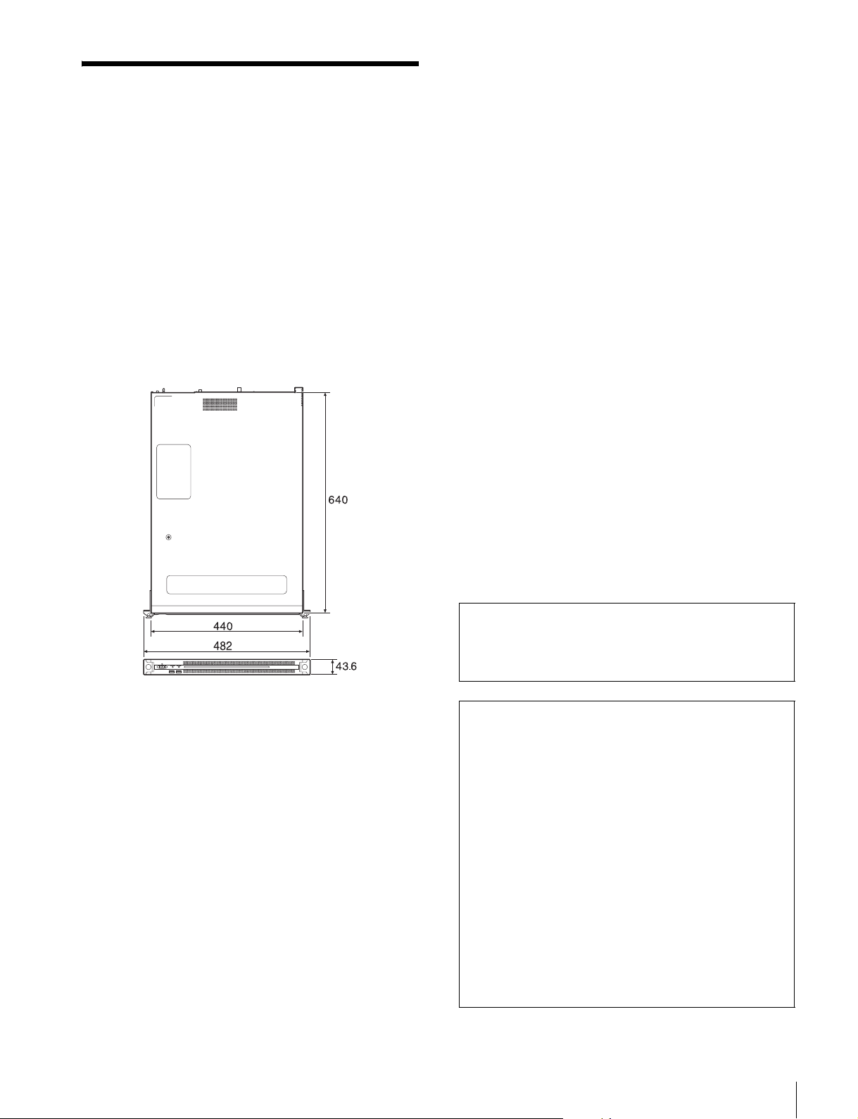
質量 14kg
外形寸法 440×43.6× 640mm(幅/高さ/奥行き)
単位:mm
1) 本機に接続されているネットワークカード
• IntelEthernetConvergedNetworkAdapterX520-DA1
ネットワークカードの情報については、以下のサイトを参照し
てください。
http://www.intel.com/support/go/network/adapter/
userguide.htm
2) SFP+ モジュール装着時のみ利用できます。
USB(前面 / 背面)
SuperSpeedUSB(USB3.0)TypeA
(6、うち前面 2、背面 4)
前面:給電対応(各 900 mA)
背面:右下のポートのみ給電対応
(900 mA)、他 3 ポートは給電非対応
HDMI TypeA(1)
HDMIVer.1.4a、
最大解像度 1920 × 1200、60Hz
DisplayPort DisplayPort(1)
DisplayPortVer.1.1a、
最大解像度 2560 × 1600、60Hz
別売アクセサリ
オプショナルパワーサプライPWSK-101
CPU
プロセッサー IntelCorei7-3770(3.4GHz)
メモリ 8GBytes
SO-DIMM(DDR3)(2)
ドライブ(m-SATA)
60GBytes
ドライブ(HDD)
2.5 インチ、500GBytes、12 台
拡張バス PCIeGen28Lane(30W)(2)
入出力
LAN RJ-45(2)
1000BASE-T
100BASE-TX
SFP+(1)
10GBASE-SR/LR(Add-inCard)
1)2)
仕様および外観は、改良のため予告なく変更することがあ
りますが、ご了承ください。
使用環境によってはネットワーク上の意図せぬ第三者か
ら製品にアクセスされる可能性があります。本機をネッ
トワークに接続する際には、セキュアなネットワークで
あることをご確認の上ご使用ください。
• 必ず事前に記録テストを行い、正常に記録されている
ことを確認してください。本機や記録メディア、外部
ストレージなどを使用中、万一これらの不具合により
記録されなかった場合の記録内容の補償については、
ご容赦ください。
• お使いになる前に、必ず動作確認を行ってください。
故障その他に伴う営業上の機会損失等は保証期間中お
よび保証期間経過後にかかわらず、補償はいたしかね
ますのでご了承ください。
• 本製品を使用したことによるお客様、または第三者か
らのいかなる請求についても、当社は一切の責任を負
いかねます。
• 本機内、記録メディア、外部のストレージ等に記録さ
れたデータの損失、修復、複製の責任は負いかねます。
• 諸事情による本製品に関連するサービスの停止、中断
について、一切の責任を負いかねます。
仕様
9

• Windows は、米国 MicrosoftCorporation の米国およびそ
の他の国における登録商標または商標です。
• GoogleChrome は GoogleInc.の商標または登録商標です。
その他、本書に記載されているシステム名、製品名、会社
名は一般に各開発メーカーの登録商標または商標です。な
お、本文中では、®、™ マークは明記していません。
10
仕様
English
Table of Contents
Overview ............................................................................. 12
System Configuration and Connection.................................. 12
Supported Devices............................................................. 12
Supported Drives................................................................... 12
Supported NIC....................................................................... 12
Name and Function of Parts............................................... 13
Front View..............................................................................13
Front View (Panel Removed)................................................. 13
Rear View............................................................................... 14
Setting Up ........................................................................... 15
Initial Settings........................................................................ 15
Starting and Exiting the Application..................................... 15
Application Settings .............................................................. 16
System Settings ..................................................................... 16
Maintenance Web Application Operation ........................ 16
Usage Precautions............................................................. 17
Specifications..................................................................... 18
GBGB
For safety, please read the precautions described in the PWS-100 Operation
Guide (supplied).
Table of Contents
11

Overview
Supported Devices
The PWS-100MG1 is a system that uses PWA-MGW1
Media Gateway Software for archiving files stored on a
server in a 4K-Live system to media and for retrieving files
stored in media.
Optical disc archive cartridges, Professional Discs, SxS
memory cards, and hard disk drives can be used as the
storage media.
For details about operation, refer to the Help in
PWA-MGW1.
System Configuration and
Connection
The unit connects to a server using Ethernet, and drive
units connect to USB ports of the unit.
Notice to customers
Installation of the unit should be performed by your Sony
service personnel or a technician who has received service
training.
Operation with the following devices has been certified.
Supported Drives
Operation with the following drives has been certified.
ODS drives
• ODS-D55U
• ODS-D77U
Professional Disc drives
•PDW-U1
•PDW-U2
SxS memory card USB reader/writers
•SBAC-US10
•SBAC-US20
•SBAC-US30
Supported NIC
Operation with the following 10 GbE network card has
been certified.
Intel Ethernet Converged Network Adapter X520-DA1
12
Overview / Supported Devices
Name and Function of Parts
Front View
123 4
5
a On/Standby button and indicator
Switches the unit on/off (standby state). Connecting the
power cord places the unit in standby state, and the
indicator turns on red. Pressing the On/Standby button
while in standby state turns on the unit and the indicator
turns on green. Pressing and holding the On/Standby
button for two seconds switches the unit to standby state,
and the indicator changes to red. To turn the unit on again
after switching from On state to standby state, when the
indicator is red, press and hold the On/Standby button for
three seconds or longer. The indicator goes out when the
power cord is disconnected.
b SYSTEM indicator
Indicates the status of the unit.
Green: Operating normally
Flashing green (once per second): System is booting or
transitioning to standby state.
Flashing orange (once per second): A warning has been
generated.
Front View (Panel Removed)
High-speed flashing read (four times per second): An
error has occurred.
c ACCESS indicator
Indicates the access status to storage.
Off: Not accessing storage
Blue: Accessing storage
d Front panel LED
Turns on according to settings in the web application. The
LED is configured using [001: LINE LED] in the
[Settings] page on the Maintenance screen.
e USB connectors (front panel)
Connects to a keyboard and mouse for initializing the unit.
USB devices not described in this document are not supported.
Notes
• Both USB ports on the front panel support power delivery (900 mA).
• Use SuperSpeed USB cables.
When the SYSTEM indicator or web application indicates
an error, you can remove the front panel to check the status
of the hardware components.
123 4444
a FAN indicators
If any of the fans fail, the corresponding fan indicator turns
on red.
To remove the front panel, loosen the screws on the left
and right sides and pull the panel towards you.
b POWER indicators
If either of the AC power supply units fail, the
corresponding indicator turns on red.
Name and Function of Parts
13
c TEMP indicator
If an abnormally high temperature is detected within the
unit, the indicator turns on red.
Rear View
112 3
LAN1 LAN2
565784
d HDD status indicators
If a warning is generated for an HDD, the corresponding
indicator turns on red. The indicator turns off if the
corresponding HDD fails, is in sleep state, or has been
removed.
112 34 5
a SYSTEM TC connector
Not used by this system.
b Remote connectors (1/2, 3/4, 5)
Not used by this system.
c AC power supply units
Insert the power cords and connect to power outlets.
Only one AC power supply unit is installed at the factory.
A second optional power supply unit can be installed to
provide power supply redundancy. When used in systems
that require reliability, power supply redundancy allows
the unit to continue operating even if a power supply unit
fails.
For details about installing or replacing a power supply
unit, consult your Sony sales or service representative.
d SFP+ slot
Attach to an SFP+ module.
e USB connectors (rear panel)
Connect to drive units using USB cables.
USB devices not described in this document are not
supported.
f LAN connectors
Connect to a Gigabit Ethernet network.
g HDMI connector
Connect to a monitor using an HDMI cable.
Use only Sony-brand HDMI cables.
Recommended cable (example): DLC-HE20XF
HIGH SPEED HDMI cable (2 m (6 ft.))
h DisplayPort connector
Connect to a monitor using a DisplayPort cable.
Use the following recommended cable.
• LINDY 41630 4K-compatible DisplayPort cable (1 m
(3 ft.))
The compatibility of the following displays has been
confirmed.
• ASUS: PB248Q
Note
Use an active-type cable if using a DisplayPort-DVI conversion cable or
DisplayPort-HDMI conversion cable.
Notes
• Of the four USB connectors on the rear panel, only the bottom right port
supports power delivery (900 mA). The other three ports do not support
power delivery, and should be used to connect USB devices that do not
require power supplied from the USB connector.
• Use SuperSpeed USB cables.
14
Name and Function of Parts

Setting Up
Initial Settings
Before using the unit, configure the Windows settings
within the unit. The description below describes the
standard settings in Windows 8.
Note
To reboot the unit, first shut down the unit and then turn the On/Standby
button on the front panel on again, without rebooting Windows.
1
Connect a keyboard and mouse to the USB connectors
on the front panel, and connect a monitor to the
DisplayPort connector or HDMI connector on the rear
panel.
2
Turn the On/Standby button on.
3
When the Windows login screen appears, enter “mgw”
as the user name and “mgw” as the password, and log
in.
2
Click [Change time zone] on the [Date and Time] tab,
and select the time zone.
3
Click [Change date and time] on the [Date and Time]
tab, and set the date and time.
4
Click the [Change settings] button on the [Internet
Time] tab.
5
Specify an NTP server, then click the [Update Now]
button.
6
Place a check mark in [Synchronize with an Internet
time server] to periodically correct the clock using the
NTP server.
Signing out
When finished, sign out from Windows.
1
Move the mouse cursor to the top right corner of the
screen to display the Charms bar, then click [Start].
2
Click the account name on the top right of the screen,
then click [Sign out].
Configuring the network
1
Connect a LAN cable to the LAN connector on the rear
panel of the unit, and connect the other end to the
network.
2
Click [View network status and tasks] under [Network
and Internet] in the control panel.
3
Click the device connected by LAN cable in
[Connections].
4
Click the [Properties] button.
5
Select [Internet Protocol Version 4 (TCP/IPv4)], then
click the [Properties] button.
6
Change the IP address and other settings.
7
Click the [Advanced] button to configure DNS,
WINS, and other settings.
8
When finished, click the [OK] button.
Setting the date and time
Starting and Exiting the Application
Starting PWA-MGW1
1
Turn on the unit.
2
Launch Google Chrome.
3
Enter the “localhost:8080” URL in the address bar and
press the Enter key.
If the login screen does not appear
In the Chrome menu, click [Settings] > [Show
advanced settings…] > [Reset browser settings] to
reset the browser.
4
Enter your user ID and password to log in.
Notes
•
PWA-MGW1 does not support the sleep function. You should ensure
that the unit does not go to sleep during operation.
• To change the Help interface language (English/Japanese/Chinese),
change the Language setting in Google Chrome.
In the Chrome menu, click [Settings] > [Show advanced settings…]
> [Languages] > [Language and input settings…] and drag the
desired language to the top of the list.
1
Select [Set the time and date] under [Date and Time]
in the [Clock, Language, and Region] control panel.
Setting Up
15

Exiting PWA-MGW1
1
Exit Google Chrome.
PWA-MGW1 does not terminate when exiting Google
Chrome.
To terminate PWA-MGW1 before exiting Google
Chrome, click the [Terminate] button on the
Maintenance page of the Settings screen.
Application Settings
Launch the application and configure the required system
settings.
For details about configuration, refer to the Help in
PWA-MGW1.
System Settings
Configure the system settings on the Maintenance screen
in the web application.
Maintenance Web
Application Operation
For details about the operation of the Maintenance Web
Application for system administrators, log in to the unit
and click the shortcut icon on the desktop to refer to the
Operation Manual.
For details about the Maintenance screen, see
“Maintenance Web Application Operation” on page 16.
16
Maintenance Web Application Operation

Usage Precautions
Precautions for products with built-in HDD
This unit has a built-in hard disk drive (HDD). The HDD
is a precision device. If subject to shock, vibration, static
electricity, high temperature or humidity, data loss can
occur. When installing and using the unit, closely observe
the following precautions.
For details about the replacement cycle, contact your Sony
sales or service representative.
Power supply precautions
If the unit is suddenly turned off during operation, data loss
may occur. To maintain data integrity, the use of an
uninterruptible power supply (UPS) is recommended.
To disconnect the power cord or turn off the breaker,
always press the On/Standby button on the unit to stop the
unit before proceeding.
Protect from shocks and vibrations
When subject to shocks or vibrations, the HDD can be
damaged and loss of data on the HDD can occur.
• When transporting the unit, use the specified packing
material. When transporting on a dolly or similar, use a
type which does not transmit excessive vibrations.
Excessive shocks and vibrations can damage the HDD.
• Never move the unit while it is powered.
• Do not remove panels or outer parts of the unit.
• When placing the unit on a floor or other surface, place
on a level, stable surface.
• Do not place the unit near other devices that may become
a source of vibrations.
• When moving the unit, always turn the power supply off.
Wait for 30 seconds after turning power off
For a brief interval after the power is turned off, the platters
inside the HDD will still keep spinning and the heads will
be in an insecure position. During this interval, the unit is
more susceptible to shocks and vibrations than during
normal operation. For a period of at least 30 seconds after
turning power off, avoid subjecting the unit even to very
light shocks. After this period, the hard disk will be fully
stopped and the unit can be manipulated.
USB device precautions
When using the unit when connected to a self-powered
USB device (such as the ODS-D77U), the device may not
be recognized, depending on the timing of when the device
is turned on. If this occurs, turn the USB device off and on
again, or disconnect and reconnect the USB cable.
Temperature and humidity related precautions
Use and store the unit only in locations where the specified
temperature and humidity ranges are not exceeded. (Be
sure to use the unit that conforms fully to the specifications
of this unit.)
When HDD seems to be faulty
Even if the HDD is showing signs of malfunction, be sure
to observe all the above precautions. This will prevent
further damage from occurring until the problem can be
diagnosed and corrected.
Replacement of the HDD and other consumable
parts
The HDD and battery are consumable parts that will need
periodic replacement.
When operating at room temperature, a normal
replacement cycle will be about 2 to 5 years.
However, this replacement cycle represents only a general
guideline and does not imply that the life expectancy of
these parts is guaranteed. For details on parts replacement,
contact your dealer.
Usage Precautions
17

Specifications
General
Power requirement
100 V to 240 V AC
50/60 Hz
Power consumption
235 W
Standby power consumption
3W or lower
Operating temperature
5 °C to 35 °C (41 °F to 95 °F)
Storage temperature
–20 °C to +60 °C (−4 °F to +140 °F)
Operating humidity
20% to 90% (relative humidity)
Storage humidity
5% to 80%
Mass 14 kg (30 lb. 14 oz.)
Dimensions 440 × 43.6 × 640 mm (17
1
25
/4in.) (width / height / depth)
Units: mm (in.)
3
/8 × 13/4 ×
Inputs/outputs
LAN RJ-45 (2)
1000BASE-T
100BASE-TX
SFP+ (1)
10GBASE-SR/LR (Add-in Card)
1) Network card connected to the unit
• Intel Ethernet Converged Network Adapter X520-DA1
For information about the network card, visit the following site.
http://www.intel.com/support/go/network/adapter/userguide.htm
2) Supported only when SFP+ module is attached.
USB (front panel/rear panel)
Super Speed USB (USB 3.0) Type A
(6, 2 on front and 4 on rear)
Front: Power delivery support (900 mA/
port)
Rear: Power delivery support on bottom
right port (900 mA), not supported on
other three ports
HDMI Type A (1)
HDMI Ver. 1.4a,
1920 × 1200 maximum resolution,
60 Hz
DisplayPort DisplayPort (1)
DisplayPort Ver. 1.1a,
2560 × 1600 maximum resolution,
60 Hz
1)2)
CPU
Processor Intel Core i7-3770 (3.4 GHz)
Memory 8 GBytes
SO-DIMM (DDR3) (2)
Drive (m-SATA)
60 GBytes
Drives (HDD)
2.5-inch, 500 GBytes (12)
Expansion bus PCIe Gen2 8Lane (30 W) (2)
Optional accessories
PWSK-101 Optional Power Supply
Design and specifications are subject to change without
notice.
Depending on the operating environment, unauthorized
third parties on the network may be able to access the
unit. When connecting the unit to the network, be sure to
confirm that the network is protected securely.
18
Specifications

Notes
• Always make a test recording, and verify that it was
recorded successfully.
SONY WILL NOT BE LIABLE FOR DAMAGES OF
ANY KIND INCLUDING, BUT NOT LIMITED TO,
COMPENSATION OR REIMBURSEMENT ON
ACCOUNT OF FAILURE OF THIS UNIT OR ITS
RECORDING MEDIA, EXTERNAL STORAGE
SYSTEMS OR ANY OTHER MEDIA OR
STORAGE SYSTEMS TO RECORD CONTENT OF
ANY TYPE.
• Always verify that the unit is operating properly before
use. SONY WILL NOT BE LIABLE FOR
DAMAGES OF ANY KIND INCLUDING, BUT
NOT LIMITED TO, COMPENSATION OR
REIMBURSEMENT ON ACCOUNT OF THE LOSS
OF PRESENT OR PROSPECTIVE PROFITS DUE
TO FAILURE OF THIS UNIT, EITHER DURING
THE WARRANTY PERIOD OR AFTER
EXPIRATION OF THE WARRANTY, OR FOR
ANY OTHER REASON WHATSOEVER.
• SONY WILL NOT BE LIABLE FOR CLAIMS OF
ANY KIND MADE BY USERS OF THIS UNIT OR
MADE BY THIRD PARTIES.
• SONY WILL NOT BE LIABLE FOR THE LOSS,
REPAIR, OR REPRODUCTION OF ANY DATA
RECORDED ON THE INTERNAL STORAGE
SYSTEM, RECORDING MEDIA, EXTERNAL
STORAGE SYSTEMS OR ANY OTHER MEDIA
OR STORAGE SYSTEMS.
• SONY WILL NOT BE LIABLE FOR THE
TERMINATION OR DISCONTINUATION OF ANY
SERVICES RELATED TO THIS UNIT THAT MAY
RESULT DUE TO CIRCUMSTANCES OF ANY
KIND.
• Windows is a registered trademark of Microsoft
Corporation in the United States and other countries.
• Google Chrome is a trademark or registered trademark
of Google Inc.
Other products or system names appearing in this
document are trademarks or registered trademarks of their
respective owners. Further, the ®, or ™ symbols are not
used in the text.
Specifications
19

Français
Table des matières
Présentation........................................................................ 21
Configuration système et connexion..................................... 21
Périphériques pris en charge ............................................ 21
Lecteurs pris en charge.......................................................... 21
NIC pris en charge ................................................................ 21
Nomenclature.......................................................................22
Vue de face............................................................................. 22
Vue de face (Panneau retiré) .................................................. 22
Vue arrière.............................................................................. 23
Mise en service................................................................... 24
Réglages initiaux................................................................... 24
Démarrer et quitter l’application........................................... 24
Réglages de l’application ...................................................... 25
Réglages système .................................................................. 25
Fonctionnement de l’application Maintenance Web....... 25
Précautions d’utilisation.................................................... 26
Spécifications ..................................................................... 27
Afin de garantir votre sécurité, veuillez lire les précautions décrites dans le
guide d’utilisation du PWS-100 (fourni).
20
Table des matières

Présentation
Le PWS-100MG1 est un système qui utilise le logiciel de
passerelle média PWA-MGW1 pour l’archive des fichiers
stockés sur un serveur dans un système 4K-Live sur un
support et pour la récupération des fichiers stockés sur ce
support.
Vous pouvez utiliser des cartouches d’archive de disque
optique, des Professional Discs, des cartes mémoire SxS et
des disques durs comme supports de stockage.
Périphériques pris en
charge
L’utilisation des périphériques suivants a été certifiée.
Lecteurs pris en charge
Le fonctionnement avec les lecteurs suivants a été certifié.
Pour plus de détails sur le fonctionnement, consultez
l’aide du PWA-MGW1.
Configuration système et connexion
L’appareil se connecte à un serveur via Ethernet et les
unités de lecture se raccordent aux ports USB de l’appareil.
Avis à l’intention des clients
L’installation de l’appareil doit être réalisée par un
membre du personnel de service après-vente Sony ou un
technicien qui a suivi une formation.
Lecteurs ODS
• ODS-D55U
• ODS-D77U
Lecteurs Professional Disc
•PDW-U1
•PDW-U2
Lecteurs/enregistreurs USB de carte mémoire
SxS
•SBAC-US10
•SBAC-US20
•SBAC-US30
NIC pris en charge
Le fonctionnement avec la carte réseau 10 GbE suivante a
été certifié.
Adaptateur de réseau converge Intel Ethernet X520-DA1
GBFR
Présentation / Périphériques pris en charge
21
Nomenclature
Vue de face
123 4
5
a Touche on/attente et indicateur
Met l’appareil sous/hors tension (mode d’attente). La
connexion du cordon d’alimentation met l’appareil en
attente et l’indicateur s’allume en rouge. Appuyez sur la
touche marche/attente en mode d’attente pour mettre
l’appareil en marche et l’indicateur s’allume en vert.
Appuyez et maintenez la touche marche/attente enfoncée
pendant deux secondes pour mettre l’appareil en mode
d’attente et l’indicateur s’allume en rouge. Pour remettre
l’appareil sous tension après l’avoir fait passer du mode
marche au mode d’attente, lorsque l’indicateur est allumé
en rouge, appuyez et maintenez la touche marche/attente
enfoncée pendant trois secondes ou plus. L’indicateur
s’éteint lorsque le cordon d’alimentation est débranché.
b Indicateur SYSTEM
Indique l’état de l’appareil.
Vert : Fonctionne normalement
Clignote en vert (une fois par seconde) : Le système est
en cours de démarrage ou passe en mode d’attente.
Clignote en orange (une fois par seconde) : Un
avertissement a été généré.
Clignote rapidement en rouge (quatre fois par
seconde) : Une erreur s’est produite.
c Indicateur ACCESS
Indique l’état d’accès au stockage.
Eteint : Pas d’accès au stockage
Bleu : Accès au stockage
d DEL panneau avant
S’allume en fonction des réglages dans l’application web.
La DEL est configurée grâce à [001: LINE LED] dans la
page [Settings] sur l’écran Maintenance.
e Connecteurs USB (panneau avant)
À raccorder à un clavier et une souris pour l’initialisation
de l’appareil.
Les périphériques USB qui ne sont pas décrits dans ce
document ne sont pas pris en charge.
Remarques
• Les deux ports USB sur le panneau avant prennent en charge
l’alimentation fournie (900 mA).
• Utilisez les câbles USB SuperSpeed.
Vue de face (Panneau retiré)
Lorsque l’indicateur SYSTEM ou l’application web
indique une erreur, vous pouvez retirer le panneau avant
pour vérifier l’état des composants du progiciel.
123 4444
22
Nomenclature
Pour retirer le panneau avant, dévissez les vis des côtés
gauche et droit et tirez le panneau vers vous.

a Indicateurs FAN
Si l’un des ventilateurs tombe en panne, l’indicateur de
ventilateur correspondant s’allume en rouge.
c Indicateur TEMP
Si une température anormale est détectée dans l’appareil,
l’indicateur s’allume en rouge.
b Indicateurs POWER
Si l’une des alimentations CA tombe en panne, l’indicateur
correspondant s’allume en rouge.
Vue arrière
565784
a Connecteur SYSTEM TC
Non utilisé par ce système.
b Connecteurs Remote (1/2, 3/4, 5)
Non utilisé par ce système.
c Unités d’alimentation CA
Insérez les cordons d’alimentation et branchez-les dans les
prises électriques.
Une seule unité d’alimentation CA est installée au départ
d’usine.
Une deuxième unité d’alimentation optionnelle peut être
installée pour fournir une redondance d’alimentation.
Lorsqu’elle est utilisée dans des systèmes qui requièrent de
la fiabilité, la redondance d’alimentation permet à
l’appareil de continuer à fonctionner même lorsque l’unité
d’alimentation principale tombe en panne.
Pour les détails sur l’installation ou le remplacement
d’une unité d’alimentation, contactez votre service aprèsvente ou concessionnaire Sony.
d Fente SFP+
A raccorder à un module SFP+.
e Connecteurs USB (panneau arrière)
À raccorder aux unités de lecture à l’aide de câbles USB.
Les périphériques USB qui ne sont pas décrits dans ce
document ne sont pas pris en charge.
d Indicateurs d’état du disque dur
Si un avertissement est généré pour un disque dur,
l’indicateur correspondant s’allume en rouge. L’indicateur
s’éteint en cas de défaillance du disque dur correspondant,
s’il est en état de veille ou s’il a été retiré.
112 3
112 34 5
LAN1 LAN2
Remarques
• Sur les quatre connecteurs USB du panneau arrière, seul le port en bas à
droite prend en charge l’alimentation fournie (900 mA). Les trois autres
ports ne prennent pas en charge l’alimentation fournie et servent à
connecter les périphériques USB qui ne nécessitent pas une alimentation
fournie par le connecteur USB.
• Utilisez les câbles USB SuperSpeed.
f Connecteurs LAN
À raccorder à un réseau Gigabit Ethernet.
g Connecteur HDMI
À raccorder à un moniteur à l’aide d’un câble HDMI.
Utilisez uniquement les câbles HDMI de marque Sony.
Câble recommandé (exemple) : DLC-HE20XF câble
HIGH SPEED HDMI (2 m (6 pieds))
h Connecteur DisplayPort
À raccorder à un moniteur à l’aide d’un câble DisplayPort.
Utilisez le câble recommandé suivant.
• LINDY 41630 câble DisplayPort compatible 4K (1 m
(3 pieds))
La compatibilité des écrans suivants a été vérifiée.
• ASUS : PB248Q
Remarque
Si vous utilisez un câble de conversion DisplayPort-DVI ou DisplayPortHDMI, utilisez un câble de type actif.
Nomenclature
23
 Loading...