

Sony MHC-MG510AV User Manual
4-233-902-12(3)
Mini Hi-Fi
Component
System
Operating Instructions
Owner’s Record
The model and serial numbers are located on the rear panel. Record the serial number
in the space provided below. Refer to them whenever you call upon your Sony dealer
regarding this product.
Model No. _______________ Serial No. _______________
MHC-MG510AV
MHC-MG310AV
MHC-MG110
© 2001 Sony Corporation
1
Warning
To prevent fire or shock hazard, do not
expose the unit to rain or moisture.
To avoid electrical shock, do not open the cabinet. Refer
servicing to qualified personnel only.
Do not install the appliance in a confined space, such
as a bookcase or built-in cabinet.
This appliance is classified
as a CLASS 1 LASER
product.
The CLASS 1 LASER
PRODUCT MARKING is
located on the rear exterior.
To prevent fire, do not Cover the ventilation of the
apparatus with news papers, table-cloths, curtains, etc.
And don’t place lighted candles on the apparatus.
To prevent fire or shock hazard, do not place vases on the
apparatus.
Don’t throw a battery, dispose it as the
injurious wastes.
However, there is no guarantee that interference will not
occur in a particular installation. If this equipment does
cause harmful interference to radio or television
reception, which can be determined by turning the
equipment off and on, the user is encouraged to try to
correct the interference by one or more of the following
measures:
– Reorient or relocate the receiving antenna.
– Increase the separation between the equipment and
receiver.
– Connect the equipment into an outlet on a circuit
different from that to which the receiver is connected.
– Consult the dealer or an experienced radio/TV
technician for help.
The shielded interface cable recommended in this manual
must be used with this equipment in order to comply with
The limits for a digital device pursuant to Subpart B of
Part 15 of FCC Rules.
CAUTION
• The use of optical instruments with this product will
increase eye hazard.
• You are cautioned that any changes or modifications
not expressly approved in this manual could void your
authority to operate this equipment.
• Use of this appliance with some systems may present a
shock or fire hazard. Do not use with any units which
have the following marking located near output.
“WARNING! HAZARDOUS ENERGY! ...”
NOTICE FOR THE CUSTOMERS IN THE
U.S.A.
This symbol is intended to alert the
user to the presence of uninsulated
“dangerous voltage” within the
product’s enclosure that may be of
sufficient magnitude to constitute a risk
of electric shock to persons.
This symbol is intended to alert the
user to the presence of important
operating and maintenance (servicing)
instructions in the literature
accompanying the appliance.
WARNING
This equipment has been tested and found to comply with
the limits for a Class B digital device, pursuant to Part 15
of the FCC Rules. These limits are designed to provide
reasonable protection against harmful interference in a
residential installation. This equipment generates, uses,
and can radiate radio frequency energy and, if not
installed and used in accordance with the instructions,
may cause harmful interference to radio communications.
2
Note to CATV system installer:
This reminder is provided to call the CATV system
installer’s attention to Article 820-40 of the NEC that
provides guidelines for proper grounding and, in
particular, specifies that the cable ground shall be
connected to the grounding system of the building, as
close to the point of cable entry as practical.
NOTICE FOR THE CUSTOMERS IN
CANADA
CAUTION
TO PREVENT ELECTRIC SHOCK, DO NOT USE
THIS POLARIZED AC PLUG WITH AN EXTENSION
CORD, RECEPTACLE OR OTHER OUTLET UNLESS
THE BLADES CAN BE FULLY INSERTED TO
PREVENT BLADE EXPOSURE.
FOR THE CUSTOMERS IN NORTH
AMERICA
ENERGY STAR® is a U.S. registered
mark.
As an ENERGY STAR
Corporation has determined that this
product meets the ENERGY STAR
guidelines for energy efficiency.
MHC-MG510AV/MG310AV only
This stereo system is equipped with the Dolby* Pro Logic
Surround decoder.
* Manufactured under license from Dolby Laboratories.
“Dolby”, “Pro Logic”, and the double-D symbol ; are
trademarks of Dolby Laboratories. Confidential
unpublished works. ©1992-1997 Dolby Laboratories.
All rights reserved.
®
partner, Sony
®

Table of Contents
Parts Identification
Main unit ............................................... 4
Remote Control .....................................5
Getting Started
Hooking up the system .......................... 7
Inserting two size AA (R6) batteries into
the remote........................................9
Setting up your speakers for Dolby Pro
Logic* ........................................... 10
Setting the time.................................... 11
Saving the power in standby mode......12
CD
Loading a CD ......................................12
Playing a CD — Normal Play/
Shuffle Play/Repeat Play .............. 14
Programing CD tracks
— Program Play ............................ 15
Labeling a CD
— Disc Memo ............................... 16
Using the CD display .......................... 17
Tuner
Sound Adjustment
Adjusting the sound
— DBFB/GROOVE/
V-GROOVE .................................. 24
Selecting the sound effect.................... 24
Selecting the surround effect ............... 25
Enjoying Dolby Pro Logic Surround
sound* ........................................... 25
Selecting the sound formation
— Multi room selector* ................ 25
Other Features
Enhancing video game sound
— Game Sync ............................... 26
Falling asleep to music
— Sleep Timer .............................. 26
Waking up to music
— Daily Timer .............................. 26
Using an Optional Keyboard
Setting the keyboard ............................27
Labeling titles through the keyboard ... 27
Operating the system through the
keyboard ........................................ 28
Presetting radio stations.......................18
Listening to the radio
— Preset Tuning ........................... 19
Labeling the preset stations
— Station Name ............................ 19
Tape
Loading a tape ..................................... 20
Playing a tape ......................................20
Recording to a tape
— CD Synchro Recording/
Recording Manually/
Program Edit ................................. 21
Timer-recording radio programs ......... 23
Optional Components
Hooking up the optional
A/V components ........................... 28
Connecting a video game machine...... 29
Connecting a sub woofer speaker**.... 30
Connecting a DVD player* ................. 30
Additional Information
Precautions ..........................................31
Troubleshooting................................... 32
Messages ............................................. 34
Specifications ......................................35
* MHC-MG510AV/MG310AV only
**MHC-MG310AV only
3
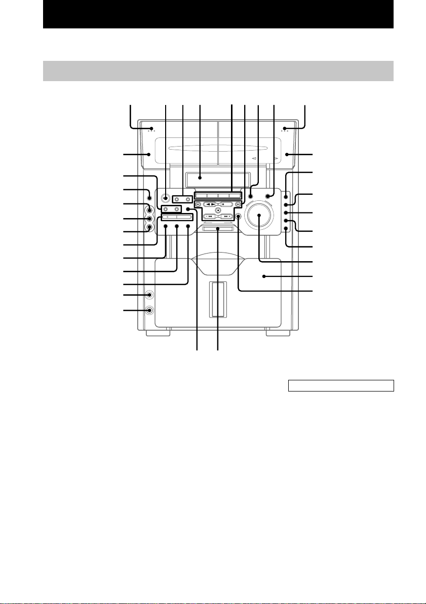
Parts Identification
The items are arranged in alphabetical order.
Refer to the pages indicated in parentheses ( ) for details.
Main unit
1
es
ea
e;
wl
wk
wj
wh
wg
wf
wd
ws
wa
5.1CH/VIDEO (MD)* 5 (28 )
AUDIO IN L jack wk (29)
AUDIO IN R jack wj (29)
CD 5 (14, 21)
CD SYNCHRO wh (21, 22)
CLEAR w; (15, 19, 34)
Deck A es (20)
Deck B 0 (20)
DIRECTION ea (20)
DISC ACCESS ql (12, 21)
Display window 4
DISPLAY wd (12, 17, 19, 34)
ENTER qk (11, 15, 18, 22, 26, 28)
FRONT* qd (25)
GAME e; (26, 29)
KEYBOARD INPUT jack ws
(27)
LINK* qg (25)
MENU ea (16, 18)
234
5
67 8 9
w; ql
PHONES jack wa
PLAY MODE wf (14, 22)
PRESET EQ 7 (24)
PRO LOGIC* qs (11, 25)
PUSH OPEN (Front cover) qj
(12)
REAR* qf (25)
REC PAUSE/START wh (21,22)
REPEAT wg (14)
STEREO/MONO wg (19)
SURROUND* qa (25)
SURROUND MODE 8 (25)
TAPE A/B 5 (20)
TIMER SELECT 3 ( 23, 27)
TIMER SET 3 (11, 23, 26)
TUNER/BAND 5 (18)
VIDEO IN jack wl (29)
VIDEO (MD)** 5 (28)
VOLUME control qh
0
qa
qs
qd
qf
qg
qh
qj
qk
BUTTON DESCRIPTIONS
Z (deck A) 1
=/1 (power) 2
m (rewind) 6
n N (play) 6
X PAUSE 6
M (fast forward) 6
x (stop) 6
– . (go back) 6
> + (go forward) 6
Z (deck B) 9
* MHC-MG510AV/MG310AV
only
**MHC-MG110 only
4
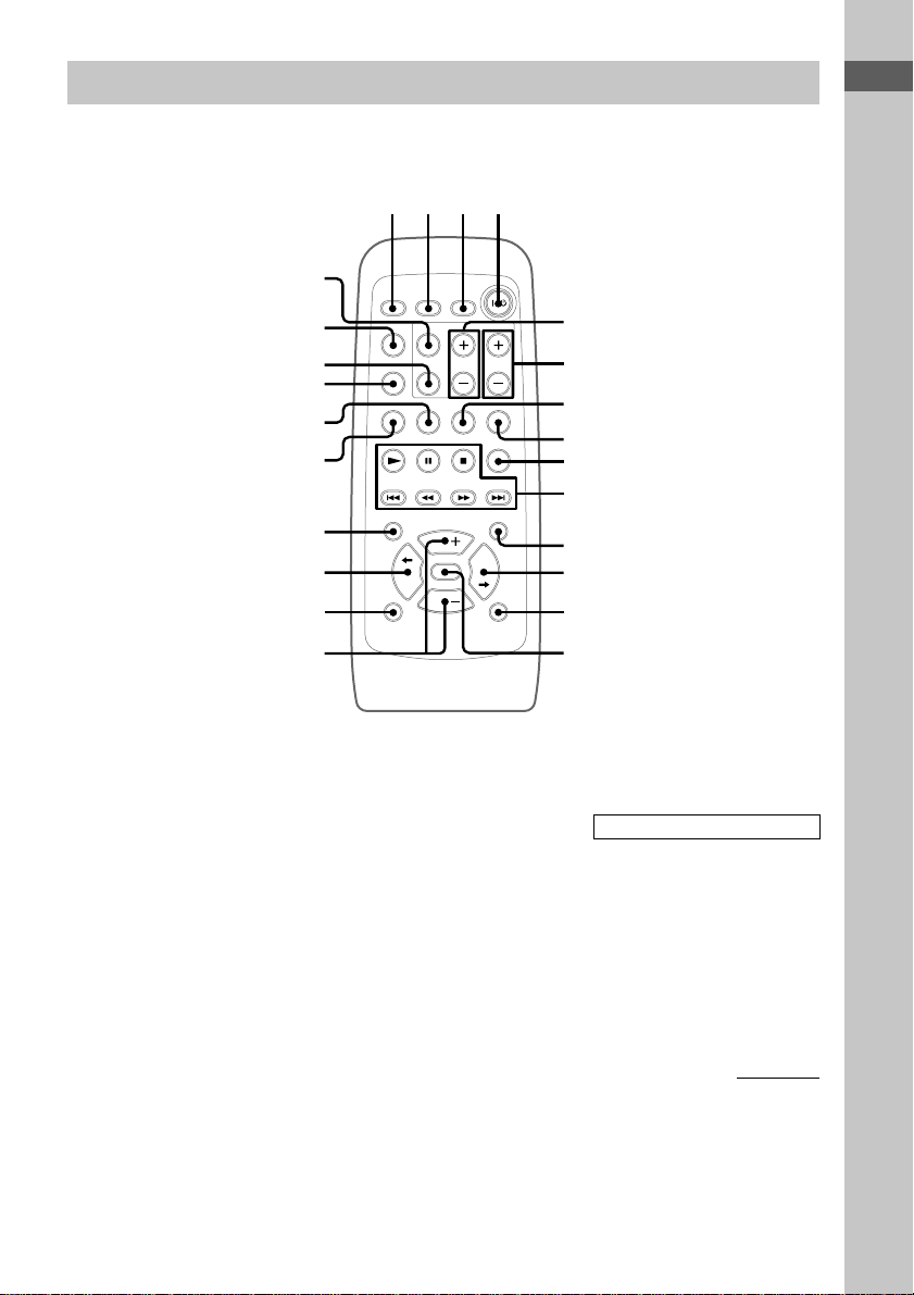
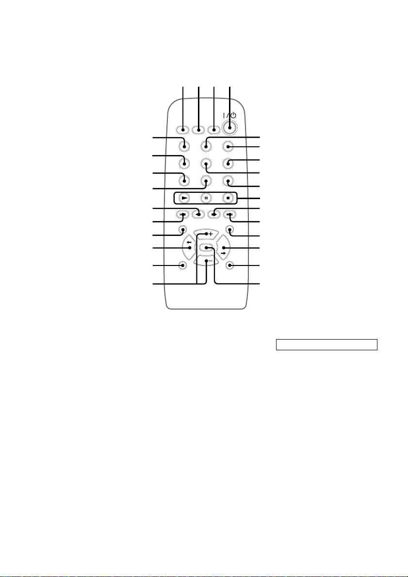
Remote Control
For MHC-MG510AV/MG310AV
1234
wf
Parts Identification
5.1CH wa (30)
CD ql (14, 21)
CENTER +/– 5 (11)
DBFB qd (24)
DISPLAY 9 (12, 17, 19)
GAME 8 (26, 29)
GROOVE qf (24)
PLAY MODE 2 (14, 22)
PRESET EQ qk (24)
PRO LOGIC wf (11, 25)
REAR +/– 6 (11)
REPEAT 3 (14)
wd
ws
wa
w;
ql
qk
qj
qh
qg
SCROLL qa (17)
SLEEP 1 (26)
SURROUND qh (25)
TAPE A/B w; (20)
TEST TONE ws (11)
TUNER/BAND 7 (18)
VIDEO (MD) wd (28)
VOL +/– qg
5
6
7
8
9
0
qa
qs
qd
qf
BUTTON DESCRIPTIONS
@/1 (power) 4
N (play) 0
X (pause) 0
x (stop) 0
. (go back) 0
m (rewind) 0
M (fast forward) 0
> (go forward) 0
TDISC/DISCt qs qj
continued
5
Remote Control (continued)
For MHC-MG110
1234
CD wf (14, 21)
CLOCK/TIMER SELECT 2
(23, 27)
CLOCK/TIMER SET 3 (23, 26)
DBFB qg (24)
DISPLAY wh (12, 17, 19)
ENTER 5 (11, 15, 18, 22, 26,
28, 34)
GAME 7 (26, 29)
GROOVE qh (24)
PLAY MODE wg (14, 22)
PRESET EQ w; (24)
REPEAT 8 (14)
wh
wg
wf
wd
ws
wa
w;
ql
qk
qj
SCROLL qd (17)
SLEEP 1 (26)
SURROUND qk (25)
TAPE A/B wd (20)
TUNER/BAND 9 (18)
VIDEO (MD) 6 (28)
VOL +/– qj
5
6
7
8
9
0
qa
qs
qd
qf
qg
qh
BUTTON DESCRIPTIONS
@/1 (power) 4
N (play) 0
X (pause) 0
x (stop) 0
. (go back) wa
m (rewind) ws
M (fast forward) qa
> (go forward) qs
TDISC/DISCt qf ql
6
Getting Started
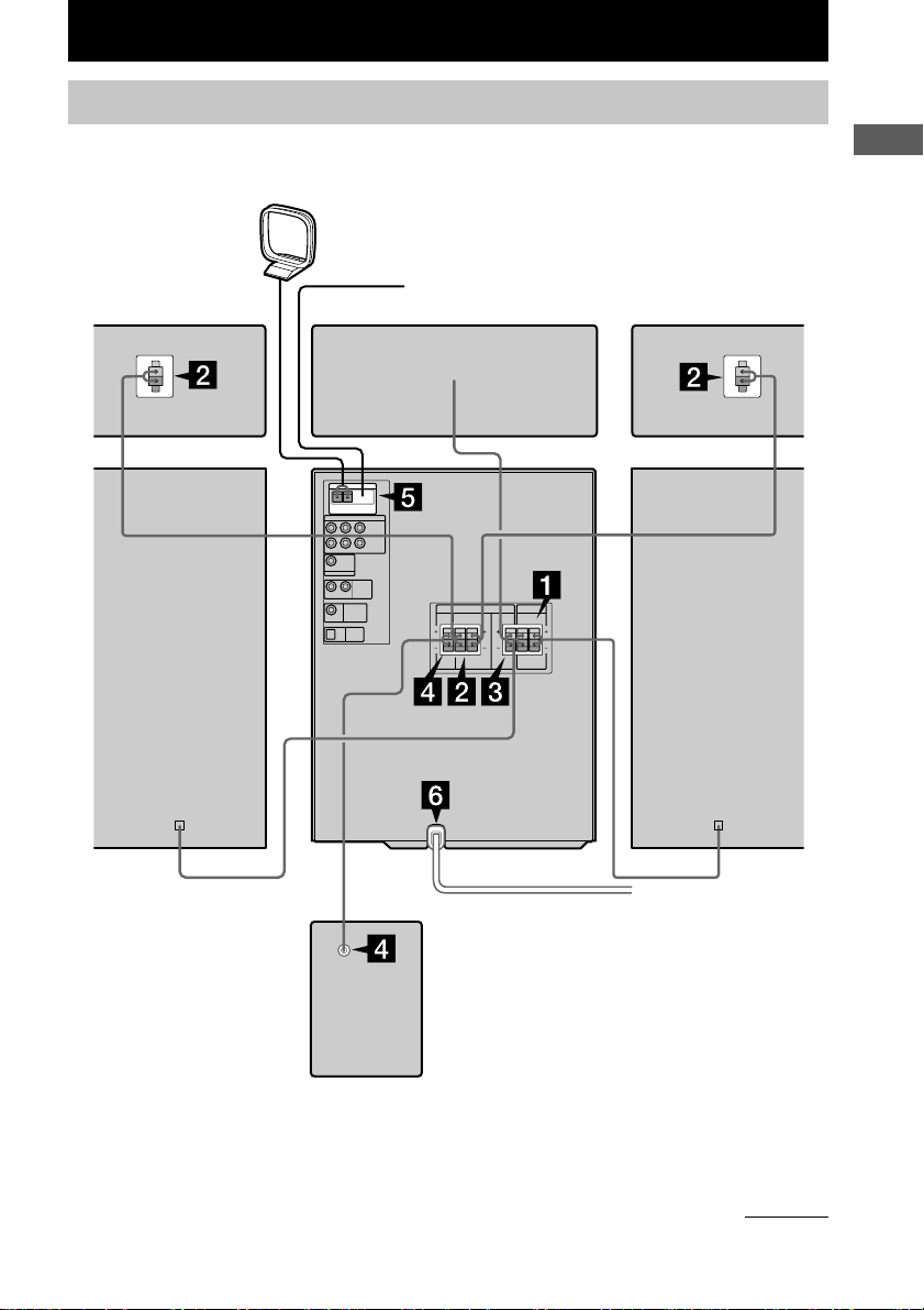
Hooking up the system
Perform the following procedure 1 to 6 to hook up your system using the supplied cords and
accessories.
AM loop antenna
Rear surround
speaker (Right)*
FM antenna
Center surround speaker*
Rear surround
speaker (Left)*
Parts Identification/Getting Started
Front speaker (Right)
Sub woofer**
MHC-MG510AV is the model used for illustration purpose.
* MHC-MG510AV/MG310AV only
**MHC-MG510AV only
Front speaker (Left)
continued
7
Hooking up the system (continued)
+
–
+
–
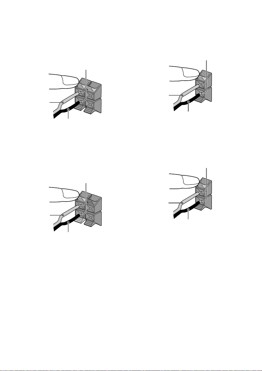
1 Connect the front speakers.
Connect the speaker cords to the FRONT
SPEAKER jacks on the unit as shown
below.
Insert only the stripped portion
R
L
3 Connect the center surround speaker.
(MHC-MG510AV/MG310AV only)
Connect the speaker cords to the
SURROUND SPEAKER CENTER jacks
on the unit as shown below.
Insert only the stripped portion
+
Red (3)
Black (#)
–
2 Connect the rear surround speakers.
(MHC-MG510AV/MG310AV only)
Connect the speaker cords to the
SURROUND SPEAKER REAR jacks on
the unit and to the jacks on the rear
surround speakers as shown below.
Insert only the stripped portion
R
L
+
Red (3)
Black (#)
–
Red (3)
Black (#)
4 Connect the sub woofer.
(MHC-MG510AV only)
Connect the speaker cords to the
SURROUND SPEAKER SUB WOOFER
jacks on the unit as shown below.
Insert only the stripped portion
Red (3)
Black (#)
8
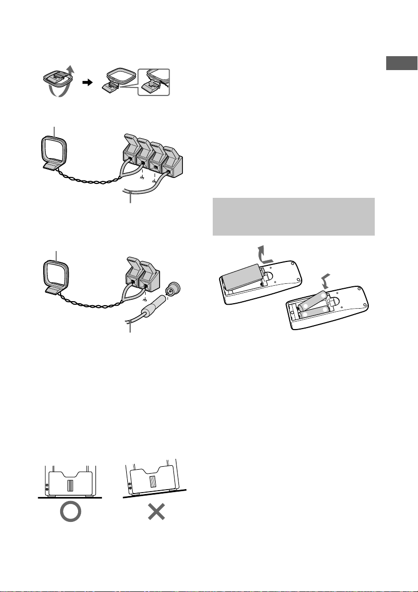
5 Connect the FM/AM antennas.
Set up the AM loop antenna, then connect
it.
Jack type A
AM loop antenna
A
M
To connect optional components
See page 28 for details.
Notes
• Keep the speaker cords away from the antennas to
prevent noise.
• Do not place the rear surround speakers on top of a
TV. This may cause distortion of the colors in the
TV screen.
• Be sure to connect both left and right rear surround
speakers. Otherwise, the sound will not be heard.
• The type of speakers supplied vary according to the
model you purchased (see “Specifications” on
page 35).
• The MHC-MG110 speaker system is not
magnetically shielded. Therefore, leave a space of 5
FM
7
5Ω
to 10 cm or more when placing the front speakers
next to a television.
Getting Started
Extend the FM antenna
horizontally
Jack type B
AM loop antenna
AM
F
M
7
5
Ω
Extend the FM antenna
horizontally
6 Connect the power cord to a wall outlet.
The demonstration appears in the display.
When you press ?/1, the system turns on
and the demonstration automatically ends.
Note on placement
Be sure to place this unit on a horizontal place.
If the unit is slanted, it may cause malfunction
or damage to the system.
Inserting two size AA (R6) batteries into the remote
e
E
E
e
Tip
With normal use, the batteries should last for about
six months. When the remote no longer operates the
system, replace both batteries with new ones.
Note
If you do not use the remote for a long period of time,
remove the batteries to avoid possible damage from
battery leakage.
9
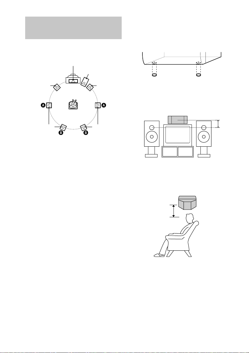
Setting up your speakers
for Dolby Pro Logic
(MHC-MG510AV/MG310AV only)
Positioning the speakers
Center
Sub woofer*
Setting the center speaker
Attach the supplied speaker pads to the bottom
of the center surround speaker to stabilize the
speaker and prevent it from slipping.
Front (L)
Rear (L)
* MHC-MG510AV only
Each speaker should face the listening position.
Better surround effect will result if all speakers
are set at the same distance from the listening
position.
Place the front speakers 5 to 10 cm or more
away from the left and right of the television.
For MHC-MG510AV, place the sub woofer on
either side of the television.
Place the center speaker on the top-center of
the TV set.
The placement of rear speakers greatly depends
on the configuration of the room. The rear
speakers may be placed on both sides of the
listening position A or behind the listening
position B.
Tip
For MHC-MG310AV customers, you can connect an
optional sub woofer speaker (see page 30).
Front (R)
Rear (R)
Place the center surround speaker at about the
same height as the front speakers. Align the
center surround speaker with the front speakers
or place it slightly back from the position of the
front speakers.
Setting the rear speakers
Place the rear surround speakers facing each
other at about 60 to 90 cm above your listening
position.
Rear surround
speaker
60 to 90 cm
10

Adjusting the speaker volume
of each speaker
— Test tone
1 Press PRO LOGIC.
“DOLBY PL ON” appears.
2 Press TEST TONE on the remote.
The test tone is heard from the speakers in
the following order.
Front (left) t Center t Front (right) t
Rear t Front (left) t
…
3 From your listening position, press
CENTER (+/–) and REAR (+/–) on the
remote to adjust the volume until the
each volume level becomes the same.
4 Press TEST TONE when you finish
adjusting.
The test tone turns off.
Note
The test tone feature works only for Dolby Pro Logic
Surround sound.
Setting the time
1 Turn on the system.
2 Press TIMER SET.
When you set the clock for the first time, go
to step 5.
3 Press – . or > + repeatedly to
select “CLOCK SET”.
4 Press ENTER.
5 Press – . or > + repeatedly to set
the hour.
6 Press ENTER.
7 Press – . or > + repeatedly to set
the minute.
8 Press ENTER.
Tip
If you made a mistake or want to change the time,
start over from step 1.
Note
The clock settings are canceled when you disconnect
the power cord or if a power failure occurs.
Getting Started
11
CD
Saving the power in standby mode
Press DISPLAY repeatedly while the
system is off. Each time you press the
button, the system switches cyclically as
follows:
Demonstration t Clock display t Power
Saving Mode
Tips
• ?/1 indicator lights up even in the Power Saving
Mode.
• The timer functions in the Power Saving Mode.
Note
You cannot set the time in the Power Saving Mode.
To cancel the Power Saving Mode
Press DISPLAY once to show the
demonstration or twice to show the clock
display.
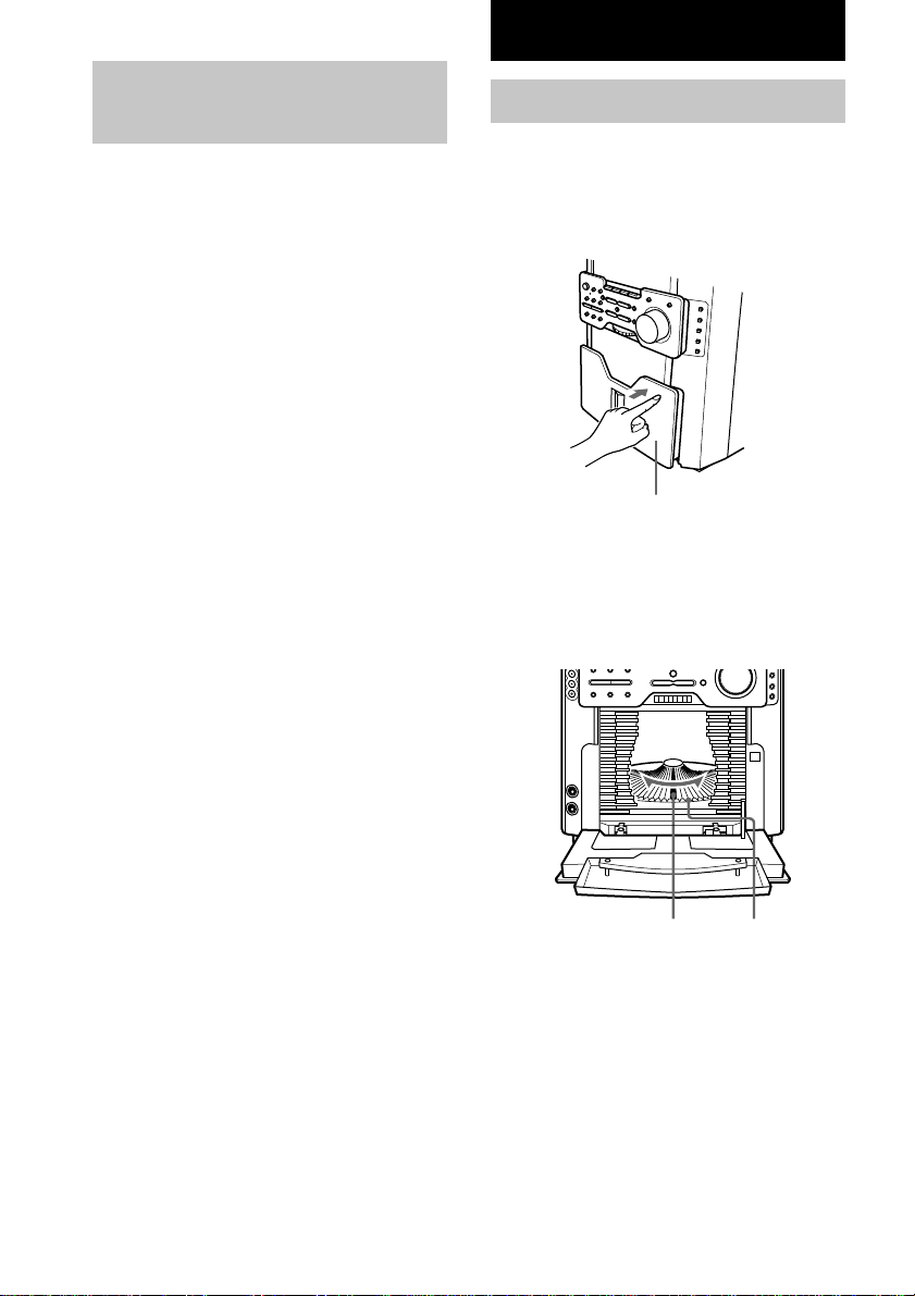
Loading a CD
You can load up to 60 discs into this unit.
Turn on the system before you load CDs.
1 Open the front cover by pushing the
right edge of the cover.
Front cover
2Turn DISC ACCESS (or press TDISC
or DISCt on the remote) until you find
the disc slot where you want to insert a
disc, while checking the disc number
(written beside every slot and also
indicated in the display).
12
Disc slot at the loading
position
(located at the very front)
Disc number
 Loading...