

SONY MHC-EX6BR, HCD-EX8BR Service Manual
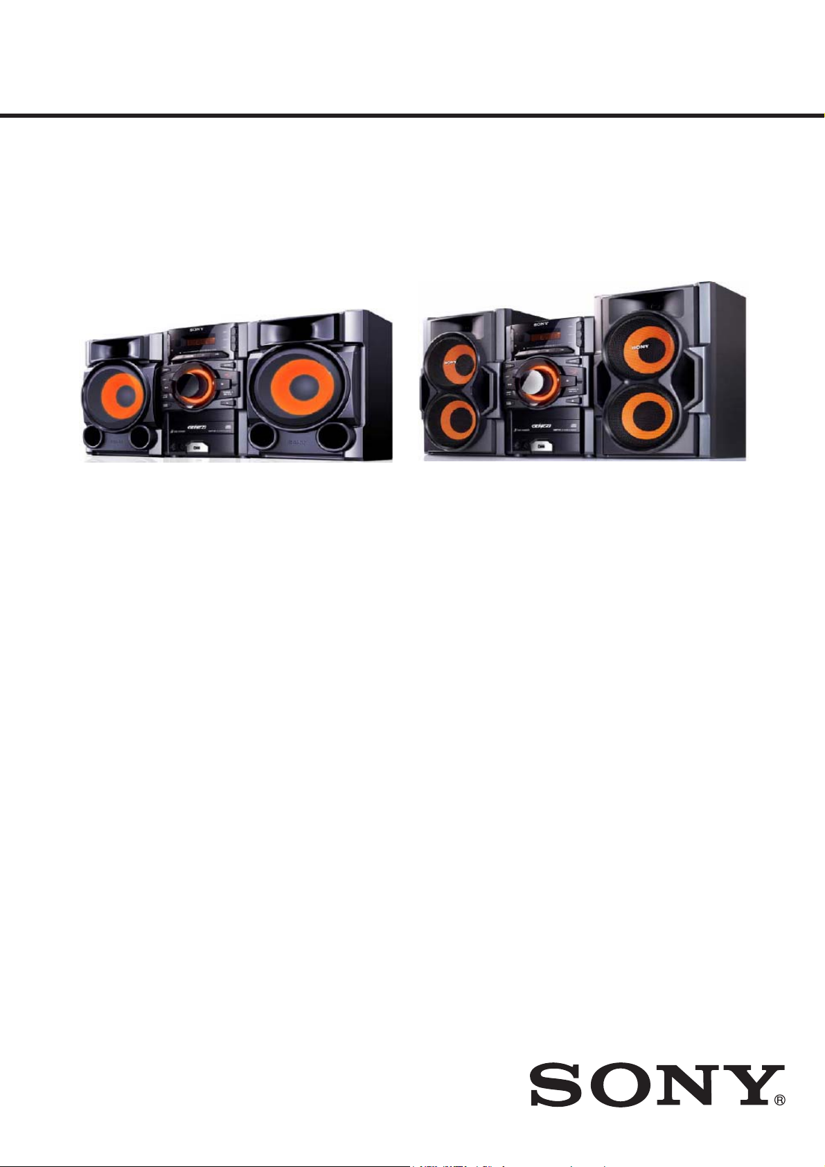
MHC-EX6BR/EX8BR
MANUAL DE SERVIÇO
Brazilian Model
Ver. 1.1 10.2010
MHC-EX6 MHC-EX8
• MHC-EX6BR/EX8BR são compostos de conforme modelos a baixo:
NOME DO MODELO DO COMPONENTE
MHC-EX6BR MHC-EX8BR
RECEIVER DE DISCO COMPACTO HCD-EX6 HCD-EX8
CAIXA ACÚSTICA FRONTAL SS-EC69 SS-EC79
ESPECIFICAÇÕES
Geral
Requisitos de alimentação
AC 127 V ou 220 V , 50/60 Hz,
ajustável com seletor de tensão
Consumo de energia
MHC-EX6BR: 110W (0.5 W no modo de economia)
MHC-EX8BR: 170 W (0.5 W no modo de economia)
Dimensões (LxAxP) (excluindo caixas acústicas)
Aprox. 200 mm × 306 mm × 350 mm
Peso (excluindo caixas acústicas)
MHC-EX6BR: Aprox. 5.6 kg
MHC-EX8BR: Aprox. 6.6 kg
Acessórios fornecidos: Controle remoto (1),
Pilhas tipo AA (2), Antena loop de AM/
Antena monofi lar de FM (1), Pes de
proteçãoo para caixas acústicas (8)
Projeto e especifi cações técnicas sujeitos a alteração sem prévio aviso.
Sony Corporation
Sony Brasil Ltda.
2010.03
©
Publicado por Product & Quality Division
ACESSÓRIOS
Ref. No. Part No. Description Remark
1-754-399-11 ANTENA, LOOP (FM /AM loop antena)
2-159-896-01 PÉ DE APOIO (8) CAIXA ACÚSTICA
4-185-062-11 MANUAL DE INSTRUÇÕES (MHC-EX6/EX8)
1-528-399-11 PILHA PEQUENA (2)
Y-8285-815-E RM-AMU006 (Controle remoto)
SISTEMA COMPACTO DE SOM
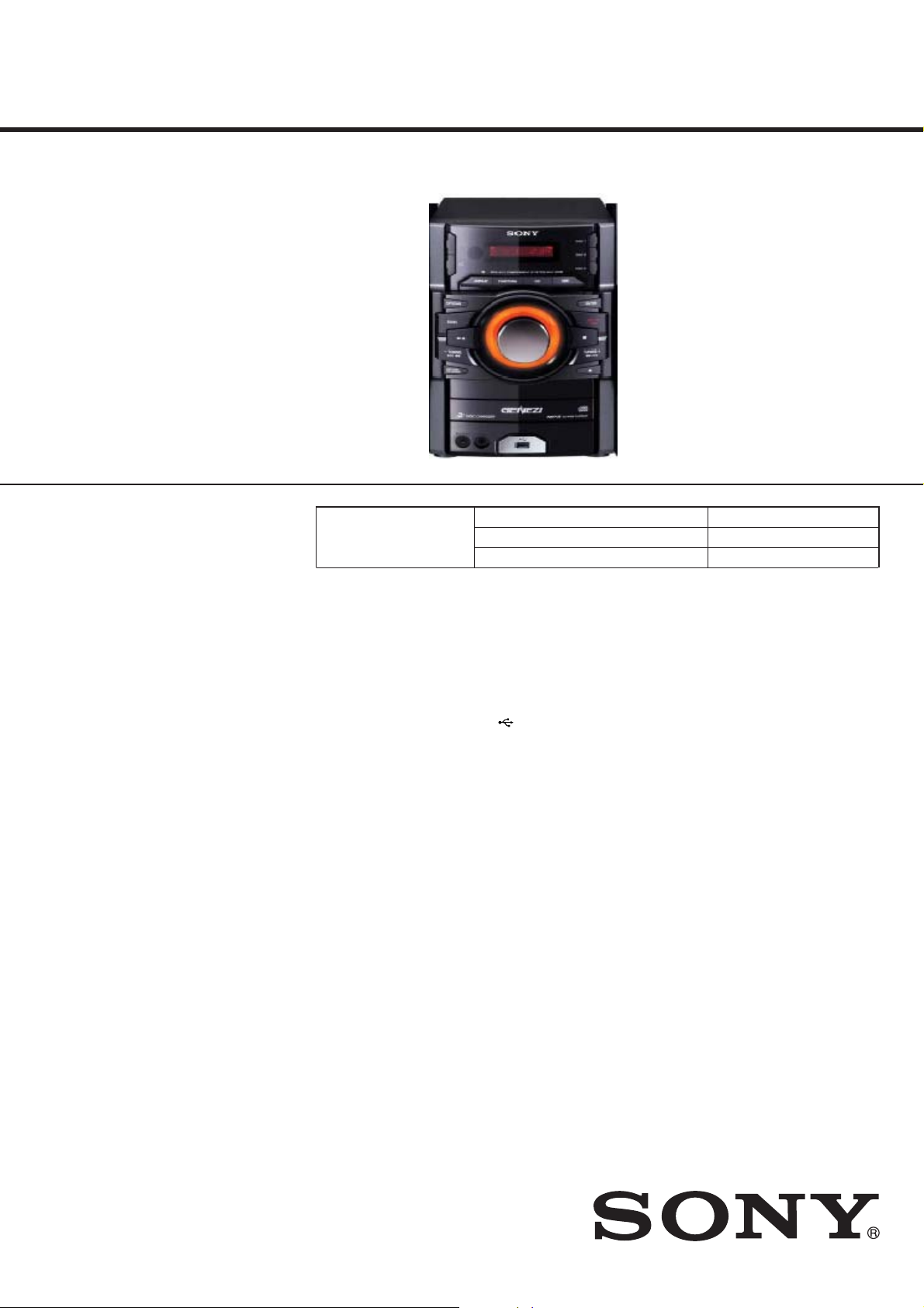
HCD-EX6/EX8
MANUAL DE SERVIÇO
Ver. 1.0 07.2010
• HCD-EX6 é o amplificador, USB,
reprodutor CD e Sintonizador do MHC-EX6
• HCD-EX8 é o amplificador, USB,
reprodutor CD e Sintonizador do MHC-EX8.
.
Seção CD
Foto: HCD-EX8
Modelo que Utiliza Mecanismo Similar Novo
Tipo de Mecanismo CDM88CL-D1BD74UR
Nome da Unidade Ótica DA11MMVGP
Brazilian Model
Seção Amplificador
Os valores a seguir foram mensurados a
127 ou 220 V CA, 60Hz
HCD-EX6
Potência de saída RMS:
140 W (70 W por canal x2, a 6 Ω,
1 kHz, 10% THD)
HCD-EX8
Potência de sa;ida RMS:
Canal de baixa frequência
300 W (150W por canal x2, a 8 Ω,
1 kHz, 10% THD)
Canal de alta frequência
300 W (150W por canal x2, a 8 Ω,
1 kHz, 1% THD)
ESPECIFICAÇÕES
Entradas
PC IN (minitomada estéreo):
Sensibilidade de 800 mV,
impedância de 22 kiloohmus
Saídas
PHONES (minitomada estéreo):
Aceita fones de ouvido com uma
impedância de 8 Ω ou mais
SPEAKERS: impedância
HCD-EX8: 8 Ω
HCD-EX6:8 Ω
Seção USB
Taxa de bits compatíveis:
MP3 (MPEG 1 Audio Layer-3):
32 kbps – 320 kbps, VBR
WMA: 48 kbps – 192 kbps
AAC: 48 kbps – 320 kbps
Frequência de amostragem:
MP3 (MPEG 1 Audio Layer-3):
32/44.1/48 kHz
WMA: 44.1 kHz
AAC: 44.1 kHz
Porta (USB):
Maximum
Corrente máxima: 500 mA
Seção do reprodutor de CD
Sistema:
Sistema de áudio digital
e disco compacto
Propriedade do diodo Laser
Duração da emissão: Contínua
Saída laser*: Inferior an 44.6μW
* Valor da saída medido a uma
distância de 200 mm, a partir da
superfície da lente da unidade
ótica com 7 mm de abertura.
Resposta de frequência: 20 Hz – 20 kHz
Relação sinal-ruído: Mais de 90 dB
Faixa dinâmica: Mais de 88 dB
Seção de sintonizador
FM estéreo, sintonizador super-heteródino
de FM/AM
Antena:
Antena monofilar de FM
Antena loop de AM
Sintonizador de FM:
Faixa de sintonização:
87.5 MHz ‒ 108.0 MHz (passos de
100 kHz)
Frequência intermediária: 225 kHz
Sintonizador de AM:
Faixa de sintonização
530 kHz ‒ 1,710 kHz (passos de10 kHz)
Frequência intermediária: 53 kHz
– Continua na próxima página –
2010.03
©
COMPACT DISC RECEIVER
Sony Corporation
Sony Brasil Ltda.
Publicado por Product & Quality Division
HCD-EX6/EX8
Geral
Requisitos de alimantação
127 ou 220 V AC, 50/60 Hz, ajustável
com seletor de tensão
Consumo de energia
HCD-EX6: 110 W
(0.5 W no modo de economia)
HCD-EX8: 170 W
(0.5 W no modo de economia)
Dimensões (LxAxP) (excluindo
caixas acústicas)
Aprox. 200 mm × 306 mm × 350 mm
Peso (excluindo caixas acústicas)
HCD-EX6: Aprox. 5.6 kg
HCD-EX8: Approx. 6.6 kg
Projeto e especificações técnicas sujeitos à
alteração sem prévio aviso.
NOTES ON CHIP COMPONENT REPLACEMENT
• Never reuse a disconnected chip component.
• Notice that the minus side of a tantalum capacitor may be damaged by heat.
FLEXIBLE CIRCUIT BOARD REPAIRING
• Keep the temperature of soldering iron around 270 °C during
repairing.
• Do not touch the soldering iron on the same conductor of the
circuit board (within 3 times).
• Be careful not to apply force on the conductor when soldering
or unsoldering.
CAUTION
Use of controls or adjustments or performance of procedures
other than those specifi ed herein may result in hazardous radia-
tion exposure.
This appliance is classifi ed as
a CLASS 1 LASER product.
This marking is located on the
rear exterior.
ÍNDICE
1. NOTAS DE SERVIÇO .......................................... 4
2. DESMONTAGEM
2-1. Tampa Lateral (R)/(L) ................................................... 8
2-2. Seção Tampa Superior ................................................... 8
2-3. Seção Painel Frontal ....................................................... 9
2-4. Placa MAIN ................................
2-5. Seção Painel Traseiro ...............
2-6. Seção Mecanismo do CD ..........
...................................
..................................
.....................
................ 12
10
.... 11
2-7. Correia (DLM3A) .......................................................... 13
2-8. Unidade Base ................................................................. 14
2-9. Placa BD74 .................................................................... 14
3. MODO DE TESTE ...................
..............................
. 15
4. AJUSTES ELÉTRICOS ...........
.......................
..... 16
5. DIAGRAMAS
5-1. Diagrama em Blocos –Seção CD/Tuner– .......
5-2. Diagrama em Blocos –Seção Tape/Audio– ......
5-3. Diagrama em Blocos –
5
-4. Placa de Circuito Impresso –Seção CD– ....................... 24
Seção Display/Power Supply–
5-5. Diagrama Esquemático –Seção CD– ............................. 25
5-6. Placa de Circuito Impresso –Seção USB– ..................... 26
5-7. Diagrama Esquematico –Seção USB– ........................... 27
5-8. Placa de Circuito Impresso –Seção Painel– ................... 28
5-9. Diagrama Esquematico –Seção Painel– ......................... 29
5-10. Placa de Circuito Impresso –Seção USB-JACK– .......... 30
5-11. Diagrama Esquematico –Seção USB-JACKn– .............. 30
5-12. Placas de Circuito Impresso –Seção MAIN-AMP– ....... 31
5-13. Diagrama Esquematico –Seção MAIN-AMP (1/2)–...... 32
5-14. Diagrama Esquematico –Seção MAIN-AMP (2/2)–...... 33
5-15. Placa de Circuito Impresso –Seção Power Supply– ...... 34
5-16. Diagrama Esquematico –Seção Power Supply– ............ 35
6. VISTA EXPLODIDAS
6-1. Seção Geral .................................................................... 44
6-2. Seção Painel Frontal .........................
....................
6-4. Seção Chassisn ....................................
6
-5. Seção Placa MAIN ......................................................... 47
6-6. Seção Mecanismo do CD (CDM88CL-D1BD74UR)
7. LISTA DE PEÇAS ELÉTRICAS .....
................
.............
...................
................
21
. 22
.....
23
.......... 45
........ 46
....
48
.. 49
SAFETY-RELATED COMPONENT WARNING!
COMPONENTS IDENTIFIED BY MARK 0 OR DOTTED LINE
WITH MARK 0 ON THE SCHEMATIC DIAGRAMS AND IN
THE PARTS LIST ARE CRITICAL TO SAFE OPERATION.
REPLACE THESE COMPONENTS WITH SONY PARTS
WHOSE PART NUMBERS APPEAR AS SHOWN IN THIS
MANUAL OR IN SUPPLEMENTS PUBLISHED BY SONY.
2

SEÇÃO 1
NOTAS DE SERVIÇOS
NOTAS SOBRE O MANUSEIO DA BLOCO DE
UNIDADE Ó
O diodo laser da unidade optica e sensÍvel a descargas eletroestáticas
podendo vir a ser danificado por descargas causadas por roupas
ou mesmo pelo corpo humano. Durante o reparo tenha cuidado para não causar danos a unidade, devido a cargas eletroestáticas e siga
corretamente os procedimentos descritos nesse manual para a execução de reparos e troca de componentes.
As placas de circuito impresso podem ser facilmente danificadas.
Tenha cuidado ao manusea-las.
NOTAS SOBRE A EMISSÃO DO DIODO LASER
O feixe laser nesse modelo é concentrado e deve ser focado na superficie reflexiva do disco, pela lente objetiva da unidade optica. Quando
estiver observando a emissão do diodo laser, tome o cuidado de estar
no minimo a 30 cm da lente objetiva.
SOLDA SEM CHUMBO
Placas que exigem o uso de solda sem chumbo sã
a marca LF (lead free) indicando que a solda não contem chumbo.
(Atenção
TICA OU BASE DA UNIDADE
o impressas com
: Algumas placas de circuito impresso podem não ter essa
marca devido ao seu tamanho reduzido.)
HCD-EX6/EX8
: IDENTIFICAÇÃO DA SOLDA SEM CHUMBO
A solda livre de chumbo tem as seguintes caracteristicas:
• Derrete a uma temperatura 40 °C maior que a solda comum.
Ferros de solda comuns podem ser usados mas a ponta tem que
ser aplicada sobre a solda por um tempo maior.
Ferros de solda com ajuste de temperatura devem ser ajustados
no valor de 350 °C.
Atenção: A impressao da placa (trilhas de cobre) pode se soltar
se a ponta permanecer por muito tempo. Tenha cuidado!
mais viscosa
• É
A solda livre de chumbo é
lidade) que a solda comum, portanto tenha cuidado com as pontes de solda, especialmente entre os pinos de IC's.
• Pode ser utilizada com solda comum
E melhor usar apenas solda sem chumbo, mas este tipo també
pode ser adicionado a solda comum.
NATA SOBRE REPARO DO IC102 DA PLACA DMB19
IC102 da placa DMB19 não pode ser substituído individualmente.
Quando esta peça é com defeito, substitua a placa montada.
DESTRAVANDO A BANDEJA DO DISCO
Esta função serve para evitar o furto de discos de aparelhos em
demosntração em lojas.
mais viscosa (flui com menor faci-
m
Procedimento para Destravar:
1. Pressione a tecla [I/
2. Pressione a tecla [CD] para selecionar função CD.
3. Enquanto pressiona tecla [
(por mais de 5 segundos).
4. A menssagem “UNLOCKED” aparecera e a bandeja estará
liberada
Nota: Quando “LOCKED” é exibido, a bandeja não será liberada ao
desligar o aparelho através do botão [I/
1 STANDBY] para ligar o aparelho.
] , pressione [Z OPEN/CLOSE]
x
STANDBY].
1
3
HCD-EX6/EX8
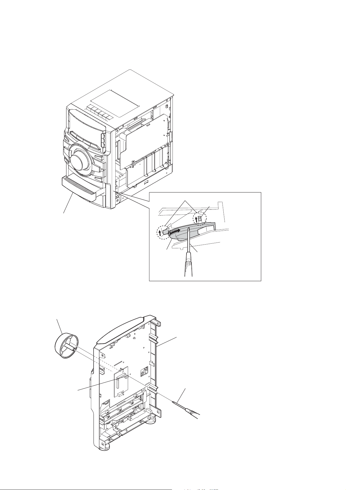
COMO ABRIR A BANDEJA QUANDO APARELHO É DESLIGADO
Nota: Favor retirar a tampa lateral (R) do aparelho e consulte item DESMONTAGEM.
Puxe a bandeja com a mão
2
COMO RETIRAR BOTÃO (VOL)
botão VOL
2
condição de abertura da bandeja do CD
alavanca
engrenagem
bloco de painel frontal
(vista traseira)
Gire a engrenagem com a
1
chave até
sobe para posição da figura
que a alvanca
Empurre o botão do VOLUME com a cheve de cabeça chata
furo
1
4
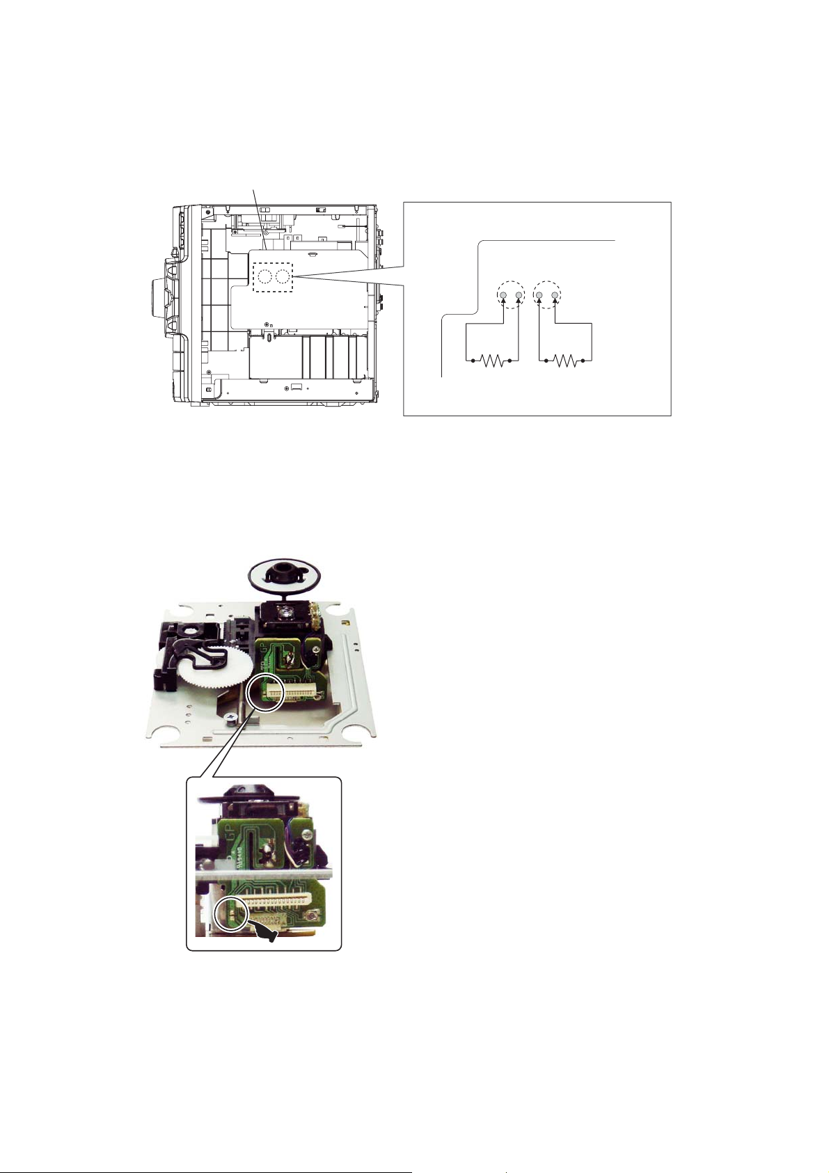
DESCARREGAMENTO DO CAPACITOR PARA PREVENIR CHOQUE ELÉTRICO
Favor retirar a tampa lateral (R) do aparelho e consulte item DESMONTAGEM.
Nota:
HCD-EX6/EX8
Placa PT-POWER
(Vista lado direito)
Para verificaçào da placa PT-POWER, descarregue os capacitores
C013 e C014 para prevenir choque elétrico.
Placa PT-POWER
00 ȍW 00 ȍW
PRECAUÇÃO PARA QUANDO SUBSTITUIR UNIDADE ÓTICA NOVA
PRECAUÇÃP PARA ANTES DE DESSOLDAR PONTO DE CURTO
DA PREVENÇÃO ELETROESTÁTICA
C013 C014
Quando substituir uma unidade ótica, conecte primeiro o cabo
flat antes de dessoldar ponto de curto anti-estática da placa de
unidade ótica.
5
HCD-EX6/EX8
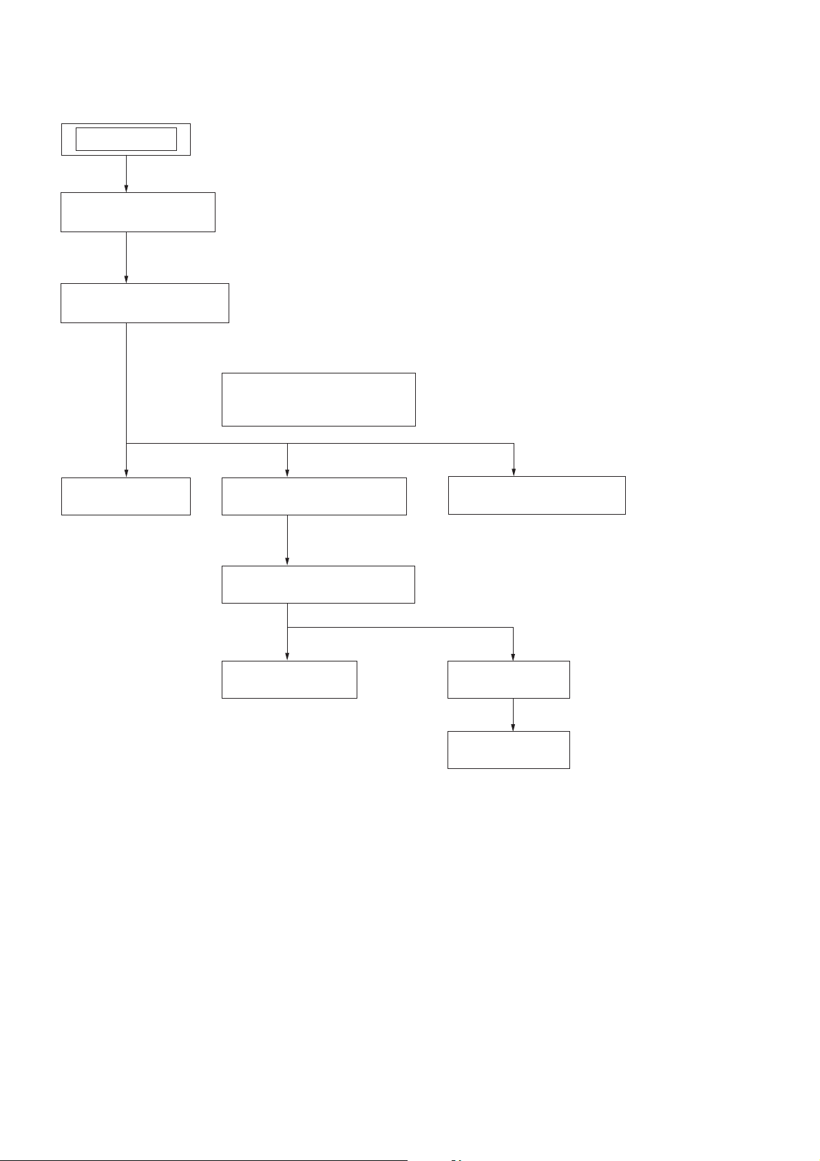
SEÇÃO 2
DESMONTAGEM
• Este aparelho pode ser desmontado seguindo a ordem numerica dada a seguir.
APARELHO
2-1.TAMPA LATERAL (R)/(L)
(Pag. 8)
2-2. TAMPA SUPERIOR
(Pag. 8)
2-5. PLACA MAIN
(Page.10)
2-4. SEÇÃO PAINEL FRONTAL
(Pag. 9)
2-7. SEÇÃO MECANISMO DO CD
(Pag. 12)
2-8.
CORREIA (DLM3A)
(Pag. 12)
2-6.
SEÇÃO PAINEL TRASEIRO
(Pag. 11)
2-9.
UNIDADE BASE
(Pag. 13)
2-10. PLACA BD74
(Pag. 13)
6
Nota: Siga o procedimento de desmontagem na ordem numerica dada.
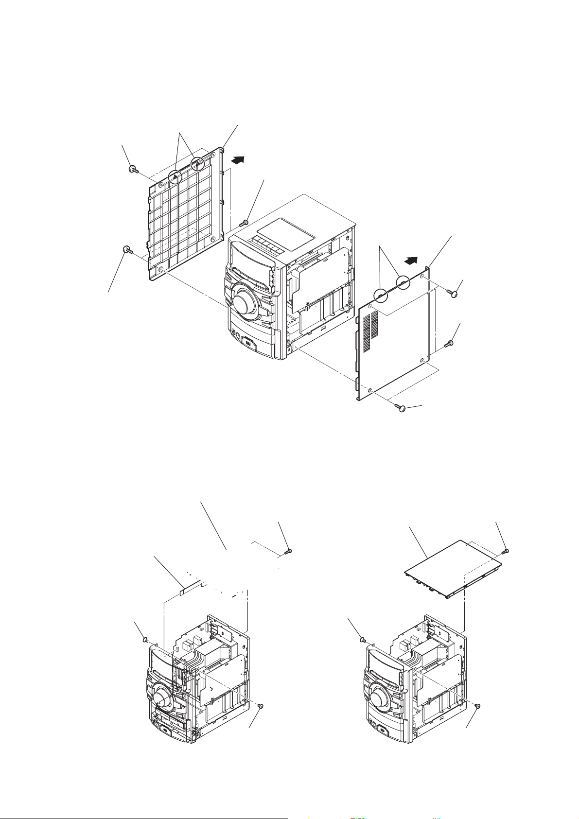
2-1. TAMPA LATERAL (R)/(L)
HCD-EX6/EX8
8 dois parafusos
(case 3 TP2)
7 dois parafusos
(case 3 TP2)
0 duas travas
qs tampa lateral (L)
qa
9 dois parafusos
(+BVTP 3 u10)
6 tampa lateral (R)
4 duas travas
5
2 dois parafusos
(case 3 TP2)
3 dois parafusos
(+BVTP 3 u10)
2-2. SEÇÃO TAMPA SUPERIOR
2 parafuso
(+KTP 3 u10)
1 dois parafusos
(case 3 TP2)
4 seçào tampa superior
3 dois parafusos
(+BVTP 3 u10)
1 parafuso
(+KTP 3 u10)
7
HCD-EX6/EX8
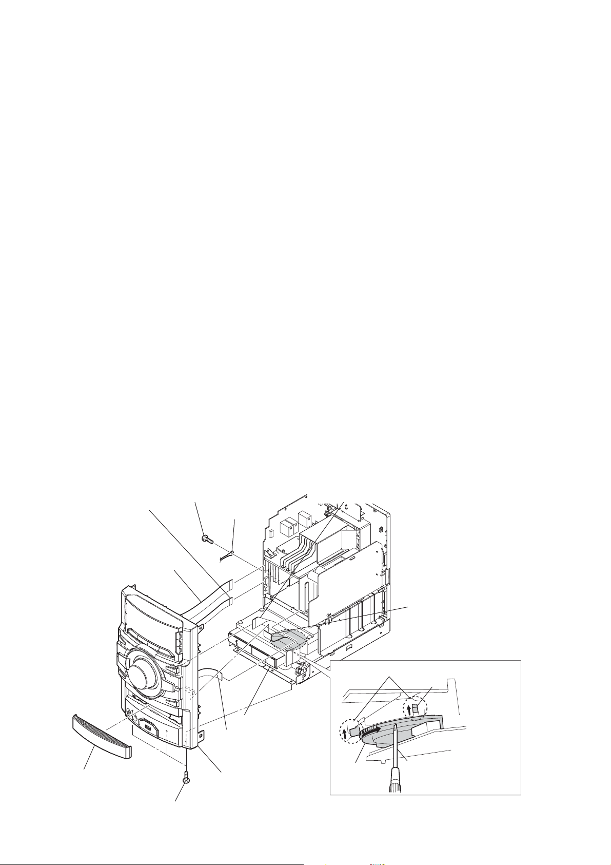
2-3. SEÇÃO PAINEL FRONTAL
9 parafuso
5 cabo tipo flat (9 vias)
(CN604)
4 cabo tipo flat (19 vias)
(CN603)
(+BVTP 3 u10)
0 lug
2
Puxe a bandeja com mão
6 cabo tipo flat (11 vias)
(CN011)
8 cabo tipo flat (25 vias)
(CN902)
7 cabo tipo flat (13 vias)
(CN302)
condição de abertura da bandeja do CD
alavanca
Gire a engrenagem com a
3 painel de carregamento
qs seção painel frontal
engrenagem
qa três parafusos
(+BVTT 3 u8)
1
chave até que a alvanca
sobe para posição da figura
8
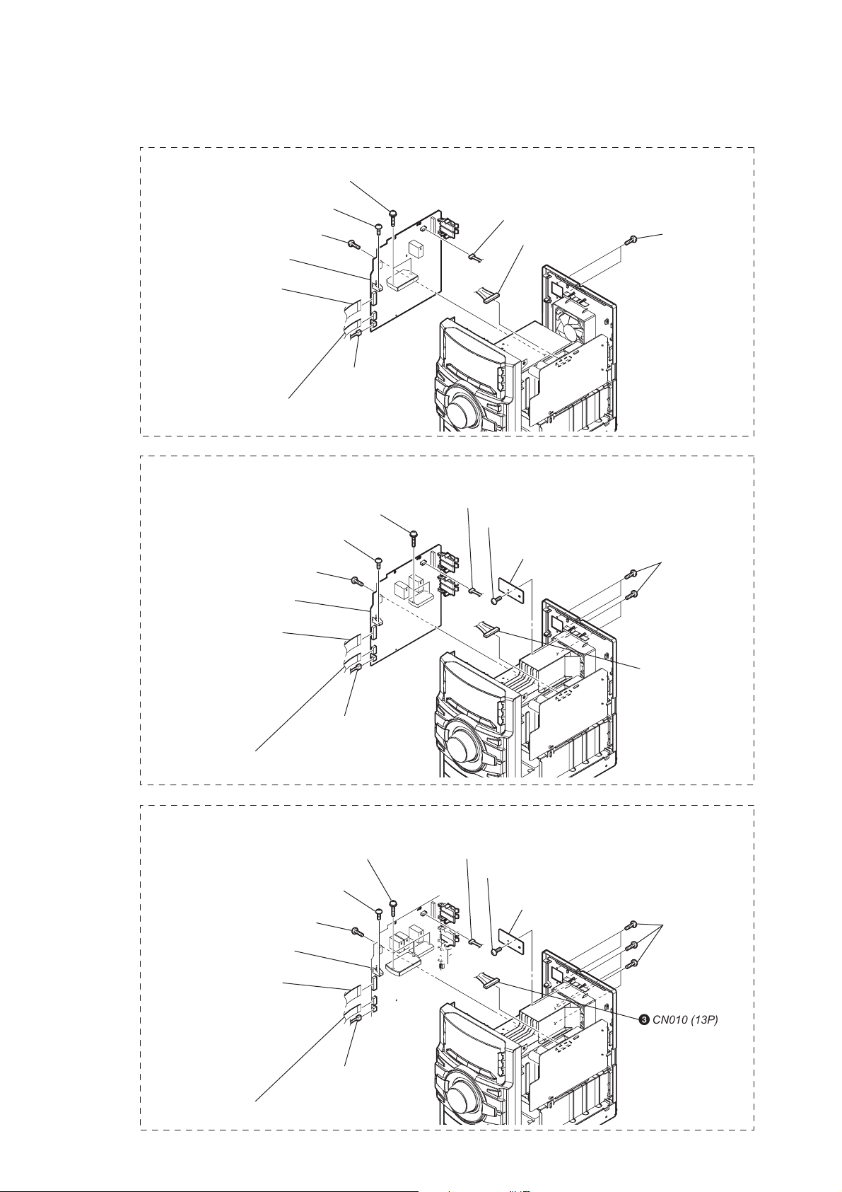
2-4. PLACA PRINCIPAL (MAIN)
EX6
8 dois parafusos
(transistor)
9 parafuso
(+BVTP 3 u10)
7 parafuso
(+BVTP 3 u10)
q; placa MAIN
3 cabo tipo flat (19 vias)
(CN603) (EX6)
4 cabo tipo flat (9 vias)
(CN604)
5 CN609 (3P)
2 CN701 (3P)
1 CN012 (10P)
HCD-EX6/EX8
6 dois parafusos
(+BVTP 3 u10)
EX8
qa parafuso
(+BVTP 3 u10)
9 parafuso
(+BVTP 3 u10)
qs placa MAIN
5 cabo tipo flat (19 vias)
(CN603) (EX8)
6 cabo tipo flat (9 vias)
(CN604)
0 dois parafusos
(transistor)
7 CN609 (3P)
4 CN701 (3P)
1 parafuso
(+BVTP 3 u10)
2 placa HOLD
8 quatro parafusos
(+BVTP 3 u10)
3 CN012 (10P)
3 CN010 (13P)
9
HCD-EX6/EX8
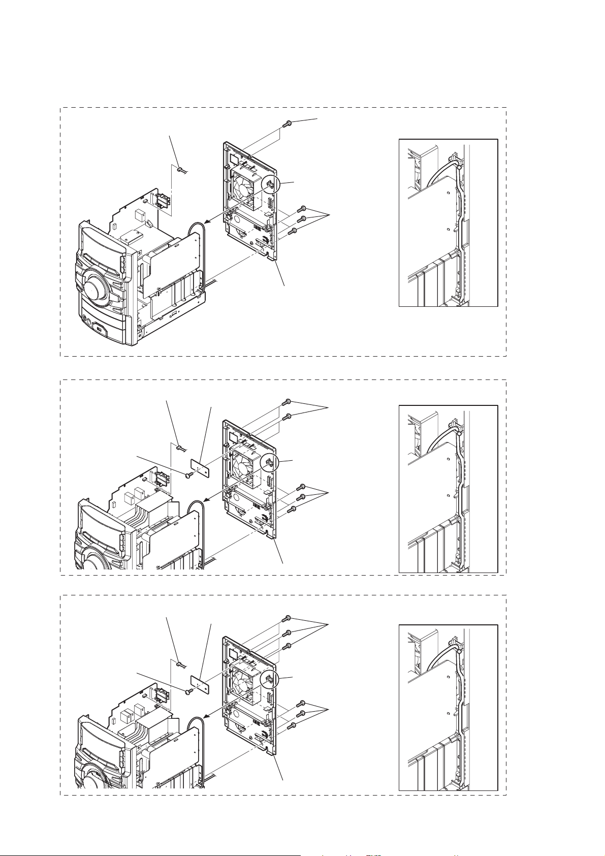
2-5. SEÇÃO PAINEL TRASEIRO
EX6
1 CN701 (3P)
3 dois parafusos
(+BVTP 3 u10)
2 Corte braçadeira
4 seis parafusos
(+BVTP 3 u10)
5 seção painel traseiro
Instalação do cabo de força
ao montar aparelho
EX8
1 parafuso
(+BVTP 3 u10)
3 CN701 (3P)
2 placa HOLD
Instalação do cabo de força
ao montar aparelho
5 quatro parafusos
(+BVTP 3 u10)
4 Corte abraçadeira
6 seis parafusos
(+BVTP 3 u10)
7 seção painel traseiro
10
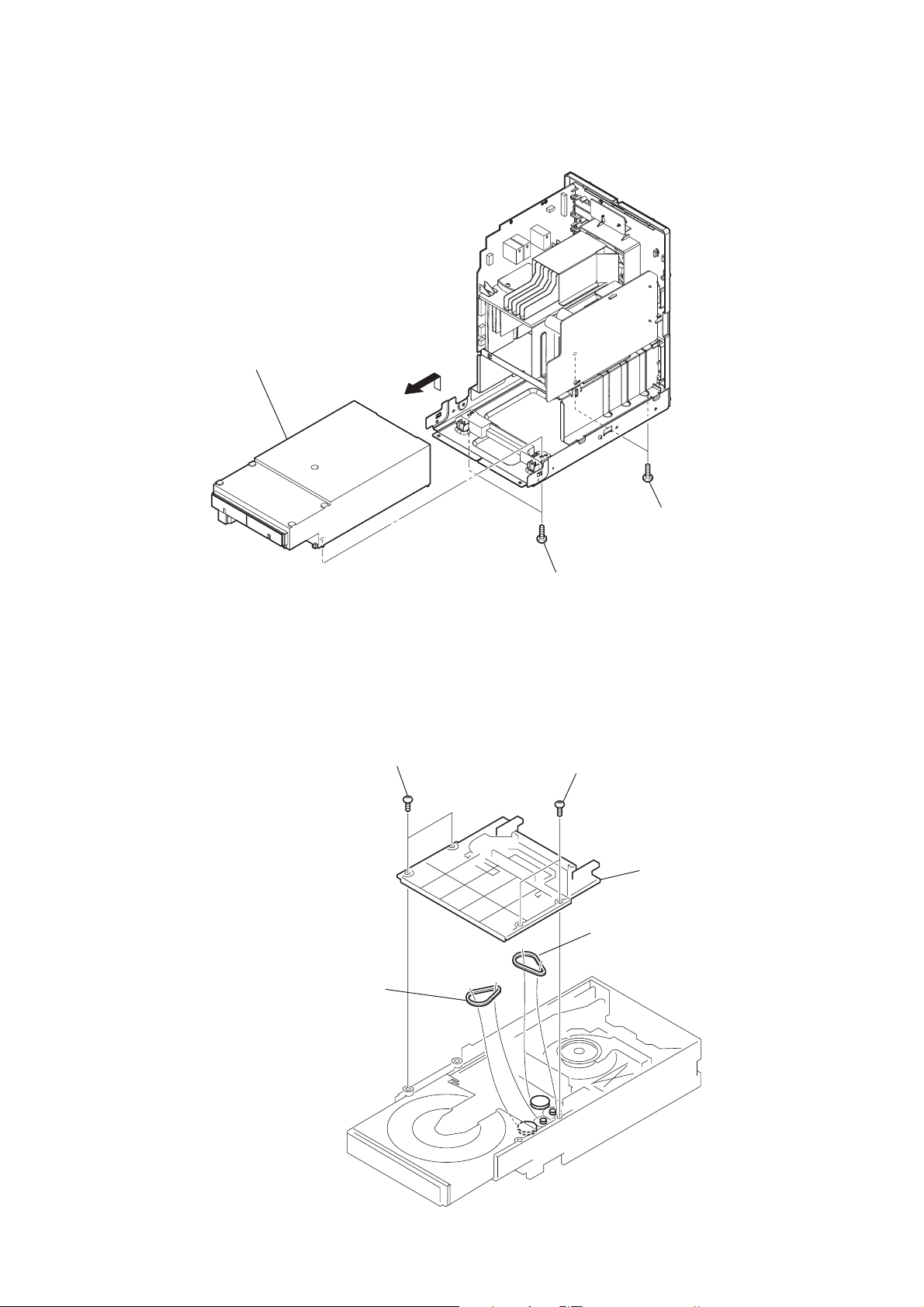
2-6. SEÇÃO MECANISMO DO CD
4 seção mecanismo do CD
HCD-EX6/EX8
3
2-7. CORREIA (DLM3A)
1 dois parafusos
1 dois parafusos
(+BVTP 3 u10)
2 dois parafusos
(+BVTP 3 u10)
2 dois parafusos
3 tampa
4 correia (DLM3A)
5 correia (DLM3A)
11
HCD-EX6/EX8
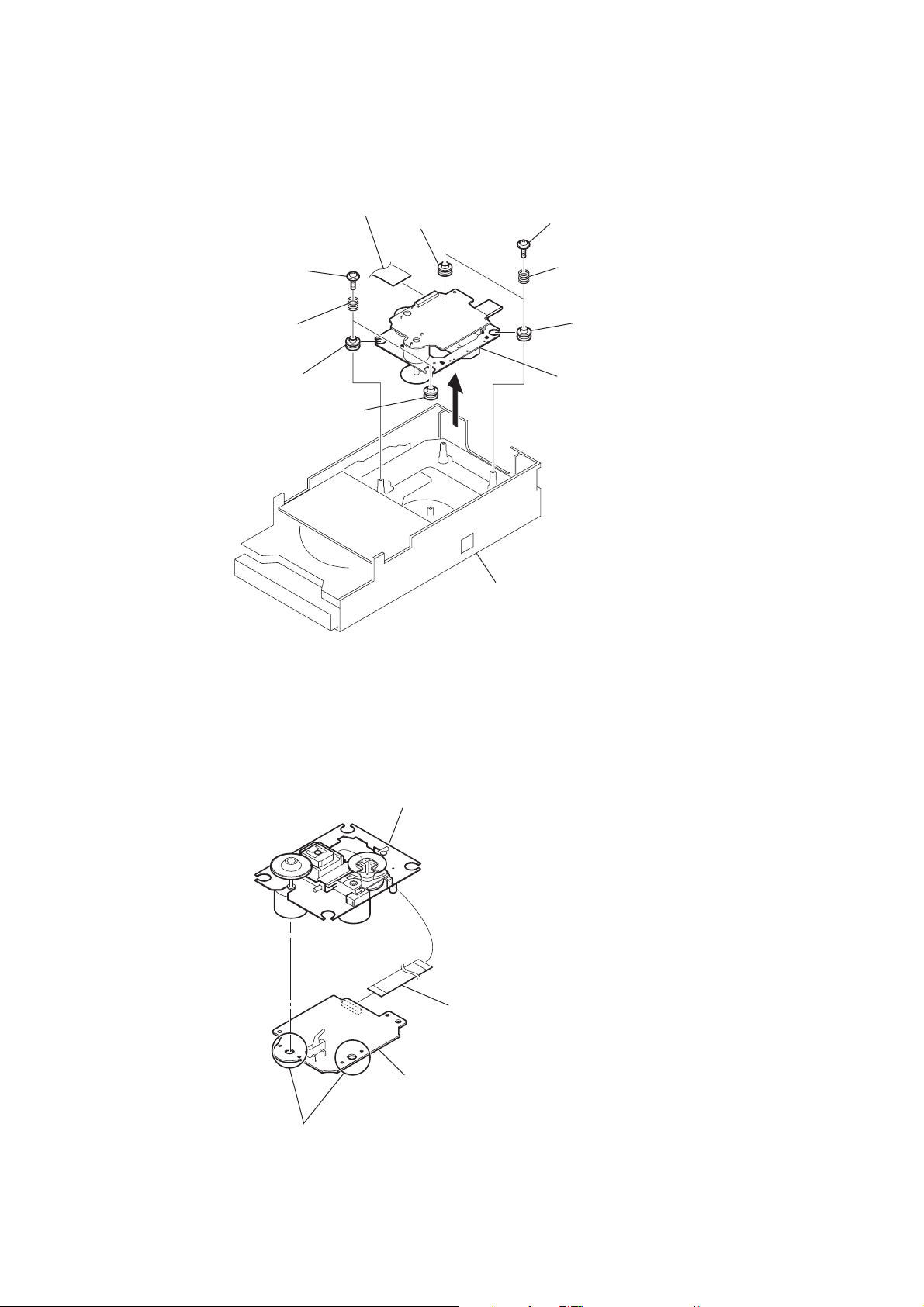
2-8. UNIDADE BASE
1 cabo tipo flat (25 vias)
(CN403)
8 amortecedor
2 dois parafusos flutuante
(+PTPWH M2.6)
4 dois parafusos flutuante
(+PTPWH M2.6)
5 duas molas espiral
(amortecedor)
9 amortecedor
0 amortecedor
3 duas molas espiral
(amortecedor)
7 amortecedor
6
bloco de mecanismo do CD
(vista inferior)
qa unidade base
2-9. PLACA BD74
base OP montado
1 cabo tipo flat (16 vias)
(CN201)
3 placa BD74
2 remova quatro pontos de solda
12

SEÇÃO 3
MODO DE TESTE
HCD-EX6/EX8
COLD RESET
The cold reset clears all data including preset data stored in the
memory to initial conditions. Execute this mode when returning
the set to the customer.
Procedimento:
1. In the standby status, press the [
] button to turn the power
?/1
on.
2. Press three buttons of [x], [FUNCTION] and [
] simultane-
?/1
ously.
3. When “RESET” appears, the set enters standby status.
MODO DE TESTE DO PAINEL
Para Entrar no Modo de Teste do Painel
Procedimento:
1. In the standby status, press the [
] button to turn the power
?/1
on.
2. Press three buttons of [DISPLAY], [x] and [OPTIONS] simultaneously.
3. When the panel test mode is activated, all LEDs and segments
of the liquid crystal display panel are all turned on.
Verificação da Versão
Procedimento:
1. In the panel test mode (all LEDs and segments of the liquid
crystal display panel are turned on), press the [FUNCTION]
button.
2. On the liquid crystal display panel, date and version are displayed “xxxxVxxx”.
3. From this status, press the [u] button, and the destination and
model name are displayed.
4. To release from this mode, press three buttons of [DISPLAY],
[x] and [OPTIONS] simultaneously.
Modo de Teste da Chave (Key)
Procedimento:
1. In the panel test mode (all LEDs and segments of the liquid
crystal display panel are turned on), press the [x] button.
2. The message “KEY0 0 0” displayed. Whenever any buttons
are pressed and the [VOLUME] control is turned, the value is
changed.
3. To release from this mode, press three buttons of [DISPLAY],
[x] and [OPTIONS] simultaneously.
MODO DE CANCELAMENTO DA REPETIÇÃO 5 VEZES DO CD
Number of repeats for CD playback is 5 times when the repeat
mode is “REPEAT”. This mode enables CD to repeat playback for
limitless times.
Procedimento:
1. Press the [
] button to turn the power on.
?/1
2. Press the [FUNCTION] button to select CD function.
3. Press three buttons of [DISPLAY], [x] and [TUNING +
] simultaneously.
L
M
4. It enters the CD repeat 5 limit cancel mode and displays “NO
LIMIT”.
5. To release this mode, press the [
] button to turn the power
?/1
off.
TRAVAMENTO DA BANDEJA DO CD
This mode is for the antitheft of CD disc in shop. (not for transport)
Procedimento:
1. Press the [
] button to turn the power on.
?/1
2. Press the [FUNCTION] button to select CD function.
3. Insert a disc.
4. While pressing the [
] button, press the [Z] button for more 5
x
seconds.
5. The message “LOCKED” is displayed and the disc tray is
locked. (Even if releasing from this mode, the disc tray is still
locked)
6. If press the [Z] button to eject the disc, the message “LOCKED”
is displayed and can not eject the disc.
7. To release this lock, while pressing the [x] button, press the
[Z] button for 5 seconds again.
8. The message “UNLOCKED” is displayed and the disc tray is
unlocked.
GERENCIAMENTO DA ALIMENTAÇÃO DO CD
This mode is for switch the CD power supply on/off. Even if this
state pulls out AC plug, it is held.
Procedimento:
1. Press the [
] button to turn the power on.
?/1
2. Press the [FUNCTION] button to select CD function.
3. Press the [
] button again to turn the power off (standby).
?/1
4. After pressing the [DISPLAY] button, while pressing the [x]
button, press the [
?/1
] button.
5. It turns power on and display “CD/USB”, then display “PWR
ON” or “PWR OFF”.
ALTERAÇÃO DO INTERVALO DE SINTONIA DO AM
The AM tuning interval can be changed over 9 kHz or 10 kHz.
Procedimento:
1. Press the [
] button to turn the power on.
?/1
2. Press the [FUNCTION] button to select TUNER AM function.
3. Press the [
] button again to turn the power off (standby).
?/1
4. After pressing the [DISPLAY] button, while pressing the
[TUNING +
ML
] button, press the [
?/1
] button.
5. It turns power on and display “9k STEP” or “10k STEP”, and
thus the tuning interval is changed over.
MODO DE TRANSPORTE (CD)
This mode can run the CD sled motor optionally. Use this mode,
for instance, when cleaning the optical pick-up.
Procedimento:
1. Press the [
] button to turn the power on.
?/1
2. Confi rm there is no disc in all trays.
3. Press the [FUNCTION] button to select CD function.
4. Press two buttons of [u] and [
] simultaneously.
?/1
5. Set to the CD ship mode (chucking on).
6. After blink “STANDBY”, “LOCK” is displayed, disconnect
the AC plug.
MODO DE TRANSPORTE(CD) E COLD RESET
Procedimento:
1. Press the [
] button to turn the power on.
?/1
2. Confi rm there is no disc in all trays.
3. Press the [FUNCTION] button to select CD function.
4. Press three buttons of [CD], [– TUNING
lm
] and [
?/1
simultaneously.
5. After blink “STANDBY”, “RESET” is displayed, disconnect
the AC plug.
]
13

HCD-EX6/EX8
MODO DE TESTE DO SERVO DE CD
This mode can check the servo system operations of the optical
pick-up system (= optical unit + BD74 board).
Note 1: Do not enter the this mode while any other test mode is in prog-
ress.
Note 2: Do not enter any other test mode while the this mode is in prog-
ress.
Como entrar no Modo de Teste do Servo de CD
Procedimento:
1. Press the [
] button to turn the power on.
?/1
2. Press the [FUNCTION] button to select CD function.
3. Press three buttons of [u], [TUNING +
ML
] and [
?/1
simultaneously.
4. It enters the CD servo test mode and displays “xx xxxx”.
Como sair do Modo de Teste do Servo de CD
Procedimento:
1. Press three buttons of [u], [TUNING +
ML
] and [
?/1
simultaneously.
2. It releases from the CD Servo Test Mode and returns to the
ordinary CD function.
Operação da Chave:
[TUNING +
ML
], [– TUNING
lm
]:
Use these keys to move the cursor to the right digit
or to the left digit in the six-digit number, when
changing the numeric value.
Press [TUNING +
ML
the right, and press [– TUNING
] to move the cursor to
lm
] to return
the cursor to the left.
MODO DE SERVIÇO DO CD
This mode can move the SLED of the optical pick-up, and also can
turn the optical pick-up laser power on and off.
Procedimento:
1. Press the [
2. Press three buttons of [u], [ENTER] and [
] button to turn the power on.
?/1
] simultane-
?/1
ously.
3. Press the [FUNCTION] button to select CD function.
4. It enters the CD service mode and displays “SERVICE”.
5. To release from this mode, press three buttons of [u], [ENTER] and [
] simultaneously.
?/1
Operação da Chave:
[TUNING +
ML
], [– TUNING
lm
]:
Use these keys to move the SLED. When [TUNING +
ML
] is pressed in this mode, the SLED
moves to outer circumference and the message
“SLED OUT” is displayed.
When [– TUNING
lm
] is pressed in this
mode, the SLED moves to inner circumference and
the message “SLED IN” is displayed.
[CD]:
Use this key to turn the optical pick-up laser power
on and off. When the laser power is turned on, the
message “LD ON” is displayed. When the laser
power is turned off, the message “LD OFF” is displayed.
MODO DA FÁBRICA DO CD
Note 1: Do not enter the this mode while any other testmode is in prog-
ress.
Note 2: Do not enter any other test mode while the this mode is in prog-
ress.
Procedimento:
1. Press the [
] button to turn the power on.
?/1
2. Press the [FUNCTION] button to select CD function
3. Press three buttons of [u], [USB] and [
] simultaneously.
?/1
4. It enters the CD factory mode and the message “FACTORY”
is displayed. When the [CD] button is pressed four times, the
]
following message (initial display) is displayed.
– – ON S
S character mode setting
]
Operação da Chave
[CD]:
[DSGX]:
RF gain setting changes whenever the button is
“-- --”: No gain fi xation.
[USB]:
[FUNCTION]:
5. To release from this mode, press three buttons of [u], [USB]
and [
?/1
Tracking servo setting
RF gain setting
The display changes in the following order whenever the button is pressed.
(Initial display)
FSCAG ** (**: Focus AGC value)
TRKAG ** (**: Track AGC value)
RF_AG ** (**: RF AGC value)
pressed.
“AL”: Fix to the gain for AL disc.
“RW”: Fix to the gain for RW disc.
Tracking servo setting changes whenever the button is pressed.
“ON”: Tracking servo ON.
“OFF”: Tracking servo OFF.
S character mode setting changes whenever the button is pressed.
“ ”: S character mode OFF.
“S”: S character mode ON.
] simultaneously.
14
HCD-EX6/EX8
SEÇÃO 4
AJUSTES ELÉTRICOS
SEÇÃO CD
Note:
1. CD Block is basically constructed to operate without adjustment.
2. Use YEDS-18 disc (Part No. 3-702-101-01) unless otherwise indicated.
3. Use an oscilloscope with more than 10 M: impedance.
4. Clean the object lens by an applicator with neutral detergent when the
signal level is low than specifi ed value with the following checks.
5. Check the focus bias check when optical pick-up block is replaced.
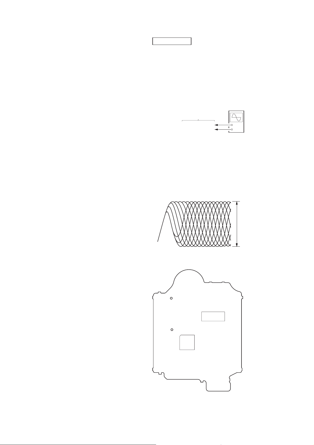
VERIFICAÇÃO DO BIAS DE FOCO
oscilloscope
(DC range)
BD74 board
CL102 (RFOUT)
CL117 (VREF)
Procedimento:
1. Connect the oscilloscope to CL102 (RFOUT) and CL117
(VREF) on the BD74 board.
2. Press the [
] button to turn the power on, and press the
?/1
[FUNCTION] button to select CD function.
3. Set disc (YEDS-18) and press the [u] button to playback.
4. Confi rm that oscilloscope waveform is as shown in the fi gure
below (eye pattern).
A good eye pattern means that the diamond shape (¸) in the
center of the waveform can be clearly distinguished.
+
–
VOLT/DIV: 200 mV
TIME/DIV: 500 ns
Checking Location:
– BD74 Board (Side B) –
CL117
(VREF)
CL102
(RFOUT)
IC101
level:
1.1 ± 0.4 Vp-p
IC301
16
HCD-EX6/EX8
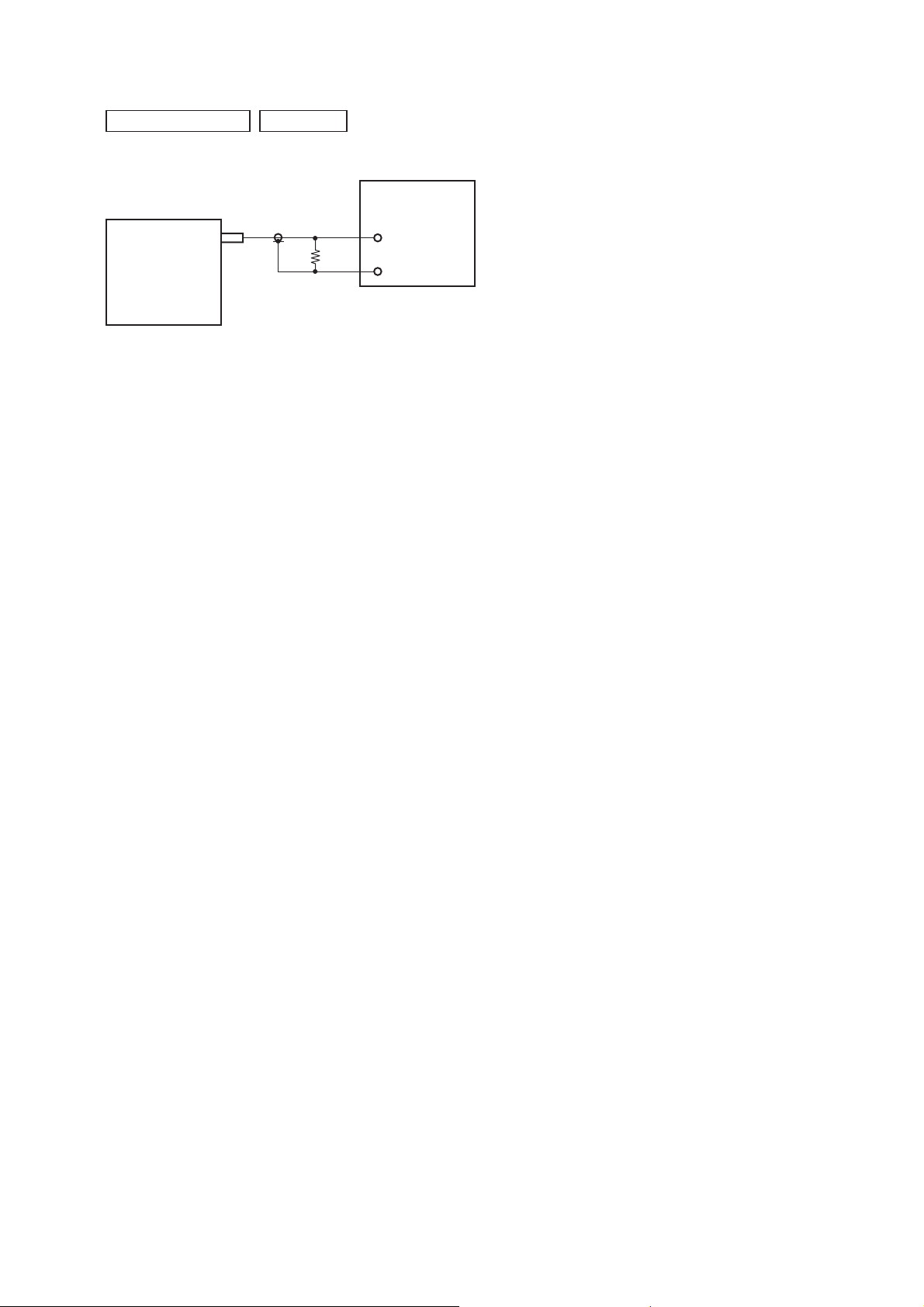
SEÇÃO TUNER
FM AUTO STOP CHECK
set
0 dB = 1 PV
signal
generator
+
75 :
–
Procedure:
1. Turn the power on.
2. Input the following signal from Signal Generator to FM antenna input directly.
Carrier frequency : A = 87.5 MHz, B = 98 MHz, C = 108 MHz
Deviation : 75 kHz
Modulation : 1 kHz
ANT input : 35 dBu (EMF)
Note: Please use 75 ohm “coaxial cable” to connect SG and the set. You
cannot use video cable for checking.
Please use SG whose output impedance is 75 ohm.
3. Set to FM tuner function and scan the input FM signal with
automatic scanning.
4. Confi rm that input Frequency of A, B and C detected and auto-
matic scanning stops.
The stop of automatic scanning means “The station signal is received in good condition”.
17
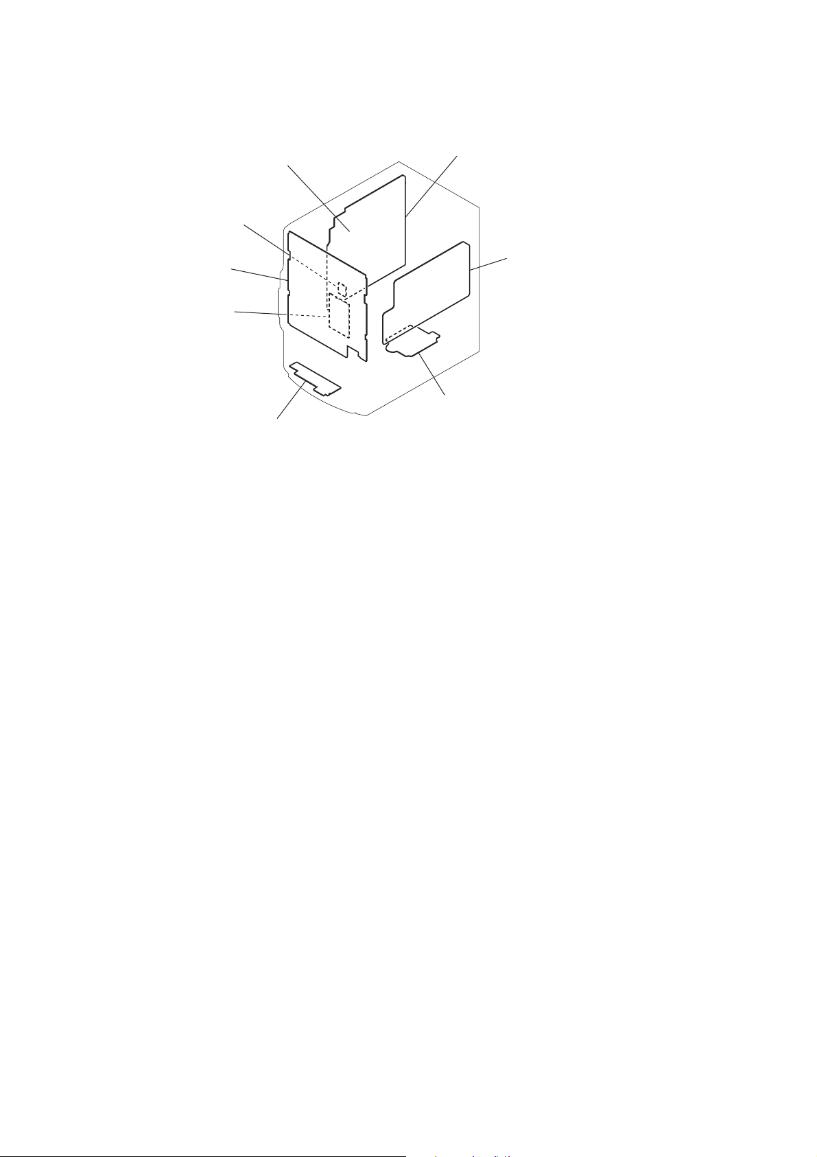
HCD-EX6/EX8
• Localização das Placas de Circuito
placa REG
SEÇÃO 5
DIAGRAMAS
placa MAIN
placa PAINEL
placa USB
placa PT-POWER
placa BD74
placa USB-JACK
18

HCD-EX6/EX8
THIS NOTE IS COMMON FOR PRINTED WIRING BOARDS AND SCHEMATIC DIAGRAMS.
(In addition to this, the necessary note is printed in each block.)
For Printed Wiring Boards.
Note:
• X : Parts extracted from the component side.
• Y : Parts extracted from the conductor side.
• W : Indicates side identifi ed with part number.
• : Pattern from the side which enables seeing.
(The other layers’ patterns are not indicated.)
Caution:
Pattern face side:
(SIDE B)
Parts face side:
(SIDE A)
Parts on the pattern face side seen
from the pattern face are indicated.
Parts on the parts face side seen from
the parts face are indicated.
For Schematic Diagrams.
Note:
• All capacitors are in PF unless otherwise noted. (p: pF) 50
WV or less are not indicated except for electrolytics and
tantalums.
• All resistors are in : and 1/4 W or less unless otherwise
specifi ed.
• f : Internal component.
• 2 : Nonfl ammable resistor.
• C : Panel designation.
Note: The components identifi ed by mark 0 or dotted
line with mark 0 are critical for safety.
Replace only with part number specifi ed.
• A : B+ Line.
• B : B– Line.
• H : Adjustment for repair.
• Voltages and waveforms are dc with respect to ground
under no-signal (detuned) conditions.
– BD74 Board –
no mark
– Other Boards –
( ) : CD PLAY
< > : TAPE PLAY
[ ] : TAPE REC
* : Impossible to measure
• Voltages are taken with VOM (Input impedance 10 M:).
Voltage variations may be noted due to normal production
• Waveforms are taken with a oscilloscope.
Voltage variations may be noted due to normal production
• Circled numbers refer to waveforms.
• Signal path.
: CD PLAY
no mark
: TUNER (FM/AM)
tolerances.
tolerances.
F : TUNER (FM)
f : TUNER (AM)
J : CD
E : USB
q : PC IN
:
19
HCD-EX6/EX8
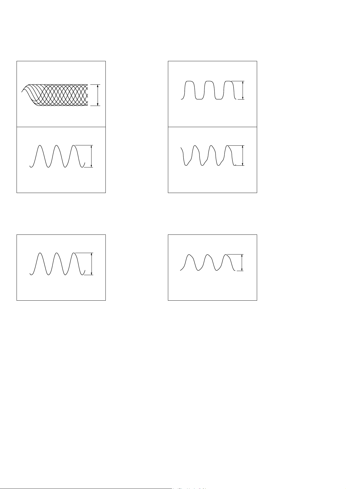
• Formas de ondas
– BD74 Board –
1 IC101 2 (RFOUT)
(CD play mode)
200 mV/DIV, 500 nsec/DIV
2 IC101 us (XOUT)
16.934 MHz
1 V/DIV, 20 nsec/DIV
0.7 to 1.5 Vp-p
2.8 Vp-p
– PANEL Board –
1 IC301 qf (X1A)
32.768 kHz
1 V/DIV, 10 Psec/DIV
2 IC301 os (X1)
6 MHz
1 V/DIV, 100 nsec/DIV
3.2 Vp-p
2.8 Vp-p
– USB Board – – MAIN-AMP Board –
1 IC901 7 (CF2)
12 MHz
1 V/DIV, 20 nsec/DIV
2.8 Vp-p
1 IC801 qh (CLK IN)
32.768 kHz
200 mV/DIV, 5 Psec/DIV
0.15 Vp-p
20
 Loading...