

Sony MDSMX-101 Service manual
MDS-MX101
SERVICE MANUAL
MDS-MX101 is the optional mini disc
deck that can be used only with section
CMT-101.
U.S and foreign patents licensed from Dolby Laboratories Licensing Corporation.
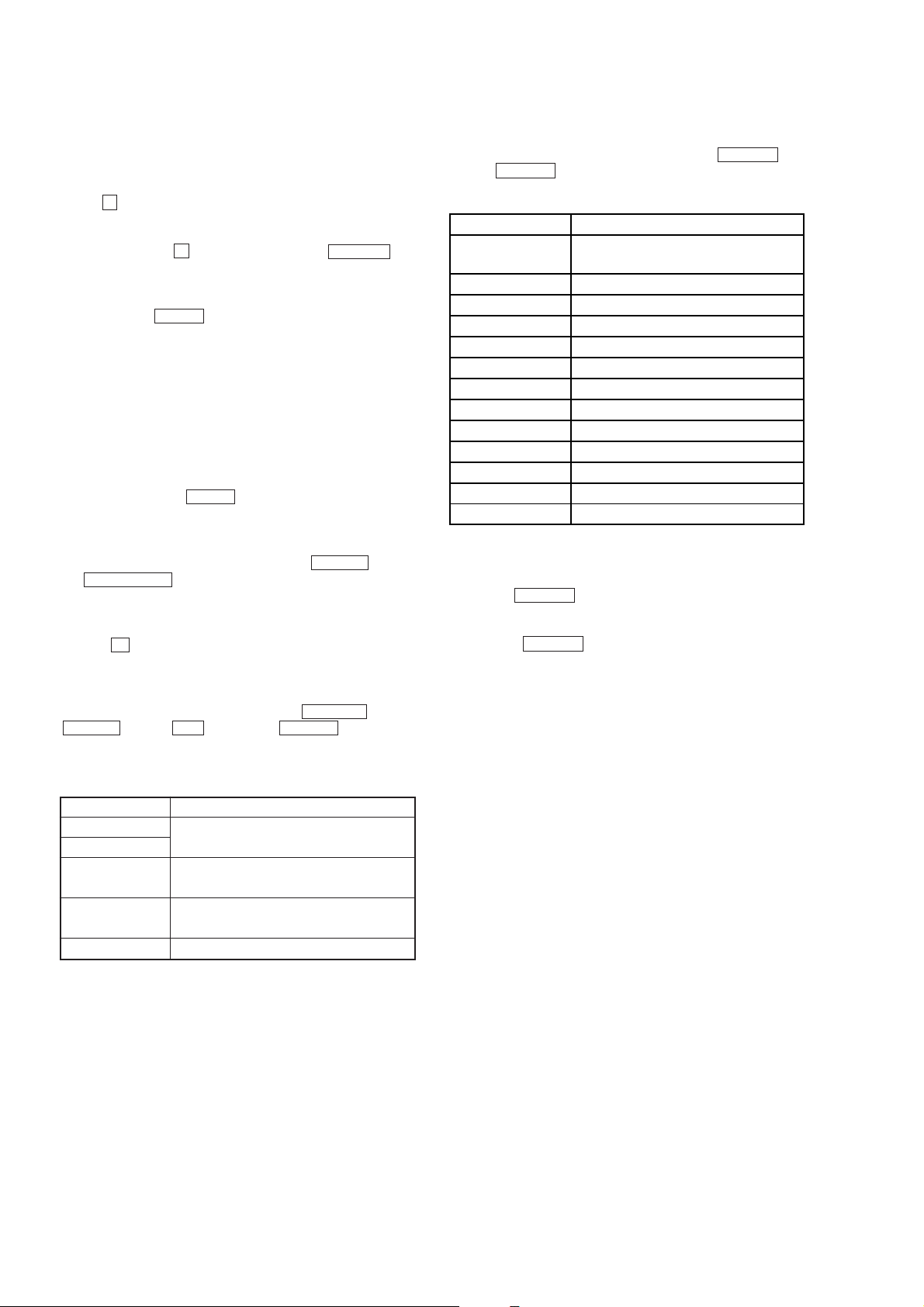
SPECIFICATIONS
AEP Model
UK Model
E Model
Tourist Model
Model Name Using Similar Mechanism MDS-S38
MD Mechanism Type
Optical Pick-up Name KMS-260A/J1N
MDM-3B
System MiniDisc digital audio system
Disc MiniDisc
Laser Semicondu2ctor laser (λ = 780nm)
Laser output power Less than 44.6 µW*
Laser diodo properties Material: GaAIAs
Revolutions (CLV) Approx. 400 rpm to 900 rpm
Error correction Advance Cross
Sampling frequency 44.1 kHz
Modulation system EFM (Eight-to-Fourteen Modulation)
Number of channels 2 stereo channels
Frequency response 5 to 20,000 Hz
Signal-to-noise ratio More than 92 dB (during playback)
Wow and flutter Below measurable limit
DIGITAL IN (MD Square optical connector jack, Optical wave length
OPTICAL IN) input/ 660 nm
DIGITAL OUT (MD
OPTICAL OUT) output
Dimeansions Approx. 142 × 125 × 235 mm (w/h/d) incl.
Mass Approx. 2 kg
Supplied accessory Digital optical cable (1)
*This output is the value measured at a distance of
200 mm from the objective lens surface on the
optical pick-up block with 7 mm aperture.
Interleave Reed Solomon Code (ACIRC)
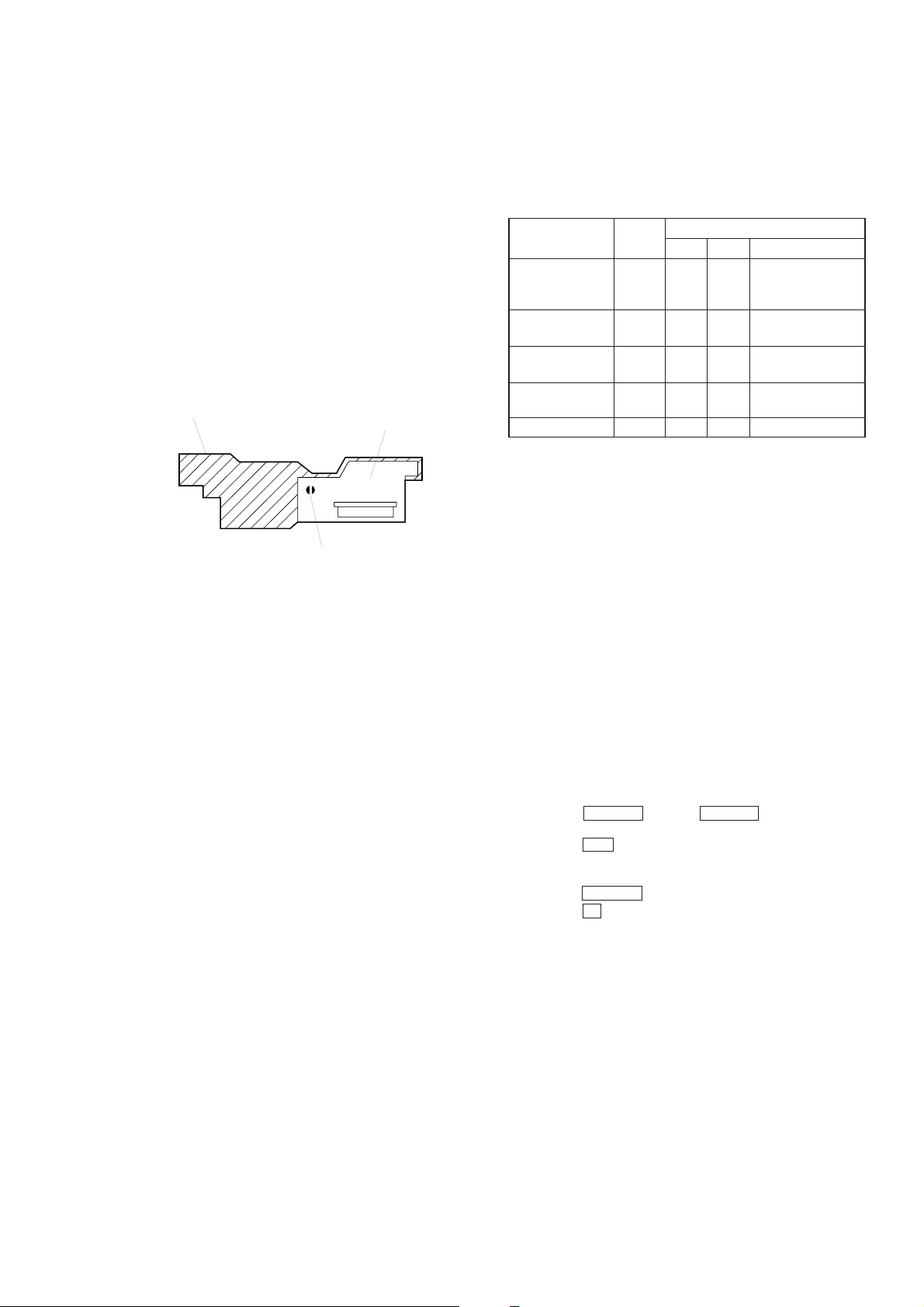
projecting parts and controls
MICROFILM
MINI DISC DECK
CAUTION
Use of controls or adjustments or performance of
procedures other than those specified herein may
result in hazardous radiation exposure.
This appliance is classified as a CLASS 1 LASER product.
The CLASS 1 LASER PRODUCT MARKING is located on
the rear exterior.
Laser component in this product is capable of emitting radiation
exceeding the limit for Class 1.
The following caution label is located inside the unit.
TABLE OF CONTENTS
1. SERVICING NOTES
1-1. Check Mode of Fluorescent Indicator Tube,
Buttons, and LED’s ........................................................ 3
1-3. Extension Cable.............................................................. 3
2. GENERAL .................................................................. 4
3. DISASSEMBLY
3-1. Cover and Front Panel .................................................... 5
3-2. Mechanism Deck ............................................................ 5
3-3. Digital Board .................................................................. 5
3-4. OPJ Board, Power Board................................................ 6
3-5. Bracket (T), (L) and (R) ................................................. 6
3-6. BD Board........................................................................ 7
3-7. Sub Chassis..................................................................... 7
3-8. Shutter Assembly............................................................ 8
3-9. Over Write Head............................................................. 8
3-10. Slider Complete Assembly ............................................. 9
4. TEST MODE........................................................ 10
5. ELECTRICAL ADJUSTMENTS ......................... 13
6. DIAGRAMS
6-1. Circuit Boards Location ................................................. 18
6-2. Block Diagram ............................................................... 19
6-3. Printed Wiring Boards
– MD Mechanism Deck Section – ................................. 22
6-4. Schematic Diagram
– MD Mechanism Deck Section – ................................. 25
6-5. Schematic Diagram – Digital Section – ......................... 31
6-6. Printed Wiring Boards – Digital Section –..................... 35
6-7. Schematic Diagram – Display Section – ........................ 38
6-8. Printed Wiring Boards – Display Section –.................... 41
6-9. Printed Wiring Boards – Power Section – ...................... 43
6-10. Schematic Diagram – Power Section – .......................... 45
6-11. IC Block Diagrams ......................................................... 47
6-12. IC Pin Functions ............................................................. 49
NOTES ON HANDLING THE OPTICAL PICK-UP
BLOCK OR BASE UNIT
The laser diode in the optical pick-up block may suffer electrostatic
break-down because of the potential difference generated by the
charged electrostatic load, etc. on clothing and the human body.
During repair, pay attention to electrostatic break-down and also
use the procedure in the printed matter which is included in the
repair parts.
The flexible board is easily damaged and should be handled with
care.
NOTES ON LASER DIODE EMISSION CHECK
The laser beam on this model is concentrated so as to be focused on
the disc reflective surface by the objective lens in the optical pickup block. Therefore, when checking the laser diode emission,
observe from more than 30 cm away from the objective lens.
7. EXPLODED VIEWS ................................................ 56
8. ELECTRICAL PARTS LIST ................................. 60
Notes on chip component replacement
• Never reuse a disconnected chip component.
• Notice that the minus side of a tantalum capacitor may be damaged
by heat.
Flexible Circuit Board Repairing
• Keep the temperature of the soldering iron around 270 ˚C during
repairing.
• Do not touch the soldering iron on the same conductor of the
circuit board (within 3 times).
• Be careful not to apply force on the conductor when soldering or
unsoldering.
CAUTION
Danger of explosion if battery is incorrectly replaced.
Replace only with the same or equivalent type recommended by
the manufacturer.
Discard used batteries according to the manufacturer’s instr uctions.
— 2 —
SECTION 1
SERVICING NOTES
1-1. CHECK MODE OF FLUORESCENT INDICATOR
TUBE, BUTTONS, AND LEDS
Setting the Check Mode:
This mode is activated by inserting the AC power cord of the PFJ1 power supply jig (or HCD-101) into AC w all outlet while pressing
the REC button and the CHARACTER button. When this mode
started, the fluorescent indicator tube and LEDs are all turned on.
1-1-1. Button Check Mode (Key Check)
When the respective buttons (12 buttons are used in total)
are pressed while all tube and LEDs are turned on, the
display area which corresponds to the pressed button, is
turned off. This mode ends by pressing the CD SYNC button
at last.
1-1-2. Fluorescent Indicator Tube Check Mode (Segment
Check)
When the button check mode ends, [Segment Check]
appears and the respective dots of the 12-digit, 5 x 7 segment
fluorescent tube are lit every other dot. This mode ends by
pressing the CD SYNC button at last.
1-1-3. Fluorescent Indicator T ube Check Mode (Scroll Check)
When the segment check ends, [Scroll Check] appears.
When the SCROLL button is pressed, the displayed letter
scrolls to the left one letter after another. When all letters
are scrolled, [end] appears. Press YES button to return to
the normal operating mode.
— BD board (Conductor side) —
CN103
Extension Cable
(J-2501-086-A)
CN200
CN102
Extension Cable
(J-2501-103-A)
CN201
— DIGITAL board (Component side) —
1-2. EXTENSION CABLE
The two types of extension cable are available during repair of this
set. The extension cable (part code no. J-2501-086-A) is available
to connect CN103 of the BD board and CN200 of the DIGITAL
board. The extension cable (part code no. J-2501-103-A) is av ailable
to connect CN102 of the BD board and CN201 of the DIGITAL
board.
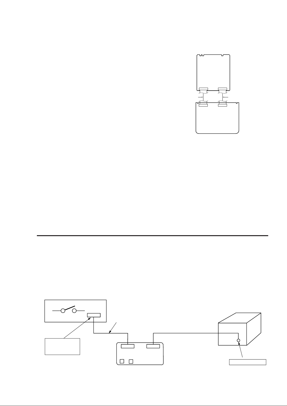
SERVICENG NOTE
• Supplying power during servicing
This equipment cannot operate without using a separate power supply. Connect the machine to the HCD-101. To apply power set the
SYSTEM POWER switch of HCD-101.
When other units are not available use the PFJ-1 power supply jig.
When using the PFJ-1, press the POWER switch of the conversion board to turn on the power.
[Connection Diagram]
PFJ-1
(Power Supply jig)
Set
POWER SW
Connector Cable 17P
(Supplied with set)
FH-E939, 838, 737,
MHC-6600, 5600,
CDP/TC
Power
Function
Conversion Board
(J-2501-144-A)
— 3 —
*
when checking the recording
function of MDS-MX101, select
any function other than MD using
the Function key of the conversion
board before check.
SYSTEM CONTROL
SECTION 2
GENERAL
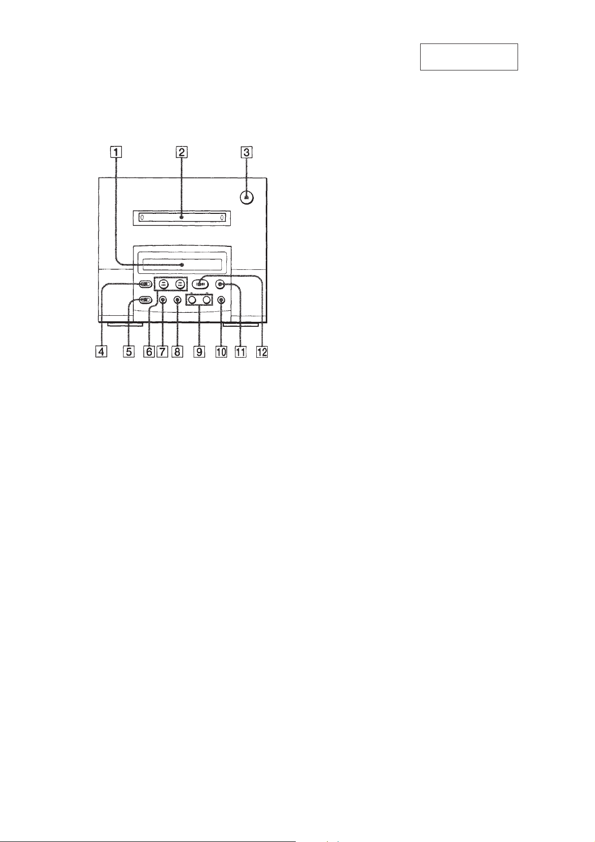
1 Display window
2 MD slot
3 6 EJECT button
4 r REC button
5 CD SYNC button
6 = 0 (finding a point in a track/
fast backward) button
) + (finding a point in a track/
fast forward) button
7 EDIT/NO button
8 YES button
9 SCROLL button, DISPLAY button/
?CURSOR/ button
0 CHARACTER button
!¡ p (stop) button
!™ ^ (play/pause) button
This section is extracted
from instruction manual.
— 4 —
SECTION 3
)
5
Two screws
(BVTT 3x8)
3
Flat type wire (23Core)
(CN203)
2
Flat type wire (29Core)
(CN201)
1
Flat type wire (19Core)
(CN200)
6
Digital board
4
Flat type wire (13Core)
(CN204)
)
DISASSEMBLY
Note : Follow the disassembly procedure in the numerical order given.
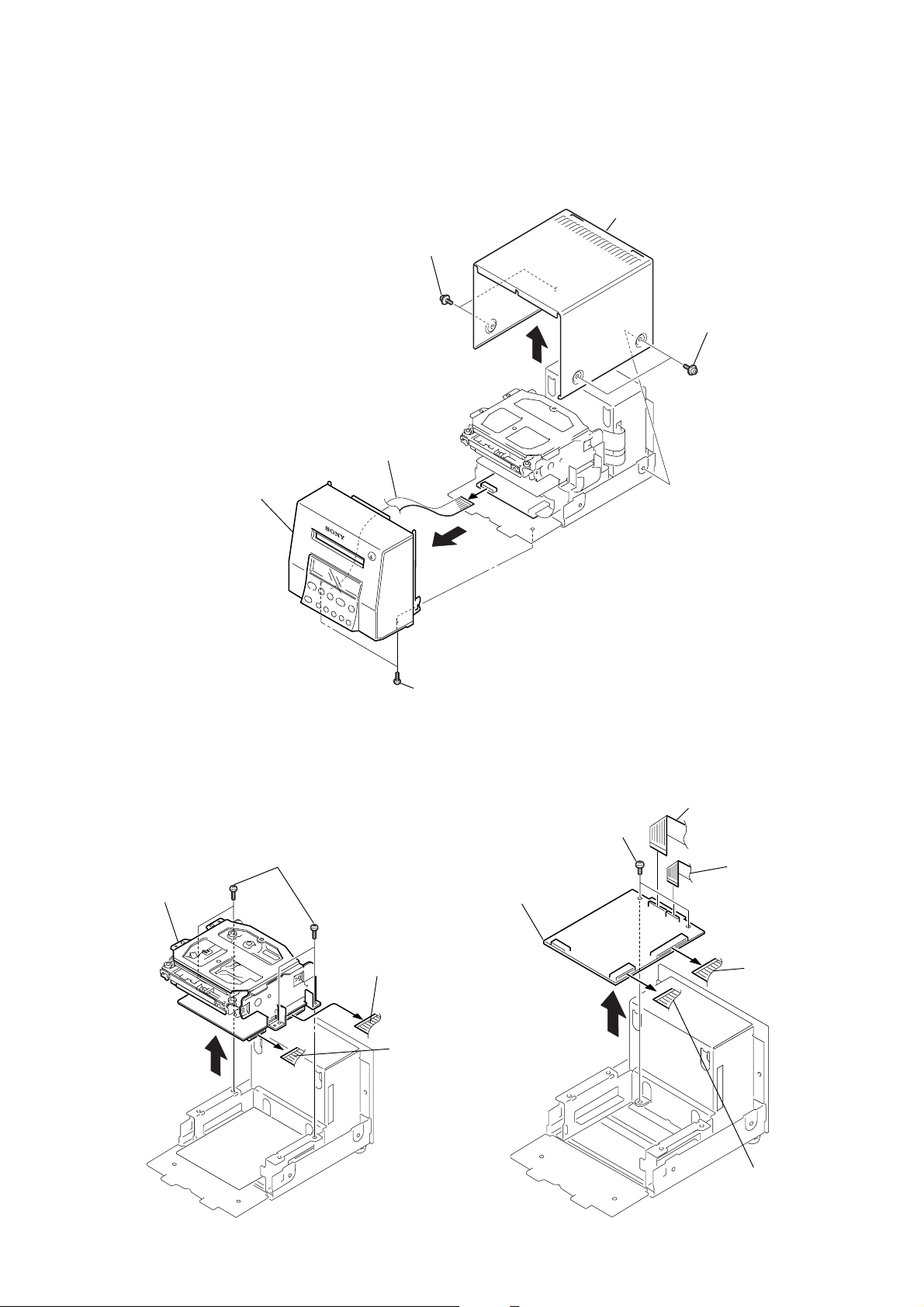
3-1. COVER AND FRONT PANEL
1
Two screws (Case)
4
Flac type wire (16Core)
(CN202)
5
Front Panel
2
Cover
1
Two screws (Case
3-2. MECHANISM DECK
1
Four Screws
(BVTT 3x8)
4
Mechanism deck
3
Two screws (BVTP 3x8)
2
Flat type wire (29Core)
(CN102)
3
Flat type wire (19Core
(CN103)
3-3. DIGITAL BOARD
— 5 —
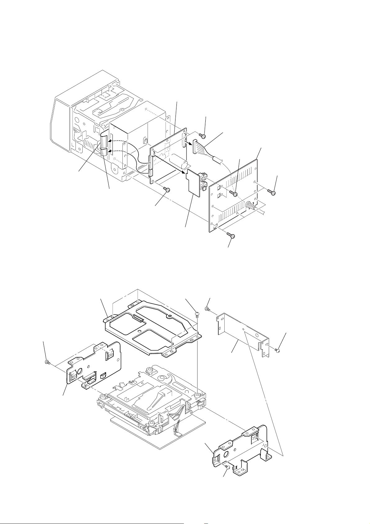
3-4. OPJ BOARD, POWER BOARD
)
6
Flat type wire
(23 Core)
7
Flat type wire
(13 Core)
5
Two screws
(BVTT 3x8)
8
Power board
4
Opj board
5
Two screws
(BVTT 3x8)
3
Cord (with Connector)
(CN102)
1
Two screws
(BVTP 3x8)
2
Back Panel
1
Two screws
(BVTP 3x8)
3-5. BRACKET (T), (L) AND (R)
2
Bracket (T)
6
Two screws
(BVTT 2x3)
7
Bracket (L)
1
Four screws
(BVTT 2x3)
1
Three screws
(BVTP 3x8)
4
Screw (BVTT 2x3)
5
Bracket (joint)
3
Screw (BVTT 2x3
— 6 —
9
Bracket (R)
8
Two screws
(BVTT 2x3)
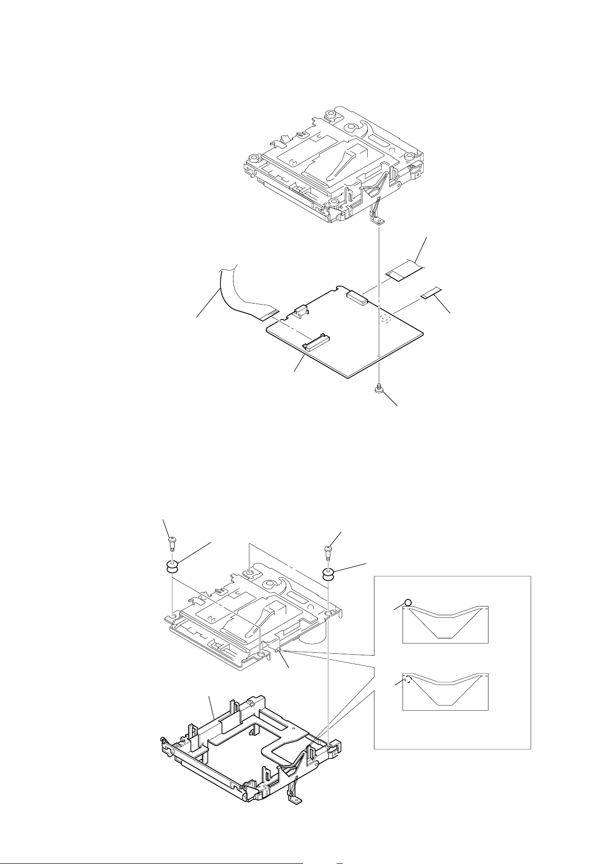
3-6. BD BOARD
4
OP relay fiexible board
(CN101)
5
BD board
2
Flat type wire (15 Core)
(CN106)
1
Flexible board
(Over write head)
3-7. SUB CHASSIS
1
Two step screws
3
Two insulatores
5
Sub chassis
Part A
2
Two step screws
3
Screw (BVTT 2x4)
4
Two insulatores
Part A
Part A
NG
OK
— 7 —
Take care so that hte part A
may be right position when installing.
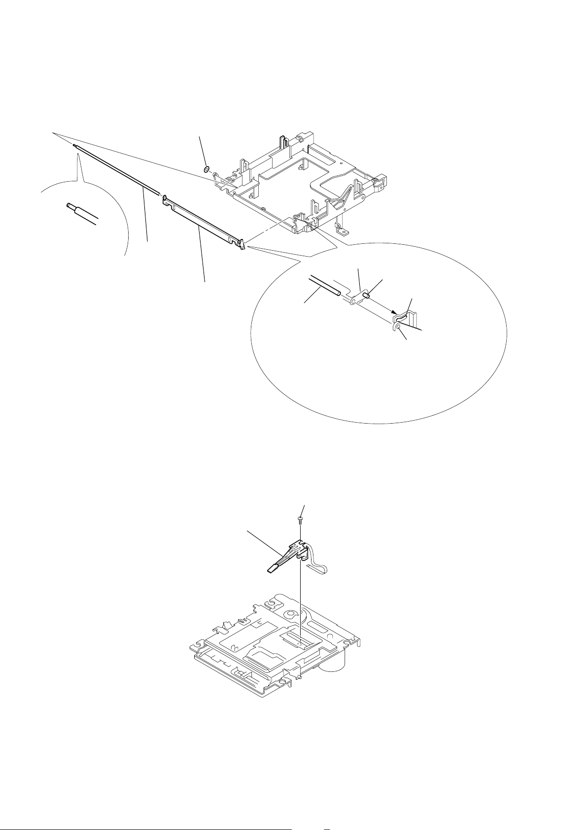
3-8. SHUTTER ASSEMBLY
)
2
Shaft (shutter)
1
Stopper washer
3
Shutter assembly
Shutter assembly
Shaft (lid) B
Hole B
Shaft (shutter) A
Hole A
When installing, install the shaft (shutter)
into the hole A as shown in the figure
before installing the shaft (lid) into the hole B.
3-9. OVER WRITE HEAD
1
Precision screw (P1.7x6
2
Over write head
— 8 —
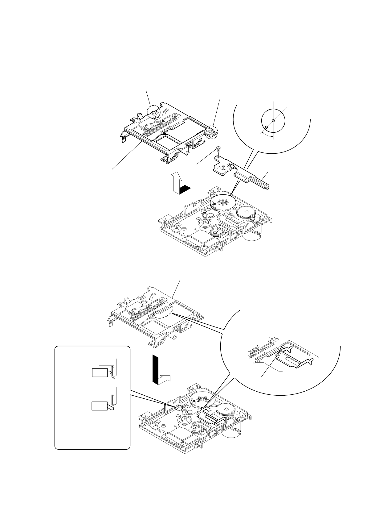
3-10 . SLIDER COMPLETE ASSEMBLY
45
°
OK
NG
3
Set the shaft of Gear (LA) to be at the
position in the figure.
2
Retainer (Gear)
1
Screw
(M1.7x2)
4
Remove the slider complete
assembly in the direction of
arrow with putting out of
two claws.
Claw
Claw
Slider assembly
Install the part A of leever (head up)
to pass over the slider complete assembly.
Part A
Take care not to damage
the detective switch.
• Note for Installation of Slider Complete Assembly
— 9 —
SECTION 4
TEST MODE
4-1. PRECAUTIONS FOR USE OF TEST MODE
1. As loading related operations will be performed regardless of
the test mode operations being performed, be sure to check
that the disc is stopped before setting and removing it. Even if
the 6 button is pressed while the disc is rotating during continuous playback, continuous recording, etc., the disc will not
stop rotating. Therefore, it will be ejected while rotating. Be
sure to press the 6 button after pressing the EDIT/NO button and the rotation of disc is stopped.
2. The erasing-protection tab is not detected in the test mode.
Therefore, operating in the recording laser emission mode and
pressing the r REC button, the recorded contents will be
erased regardless of the position of the tab. When using a disc
that is not to be erased in the test mode, be careful not to enter
the continuous recording mode and traverse adjustment mode.
4-1-1. Recording Laser Emission Mode and Operating
Button
1. Continuous recording mode (CREC MODE)
2. Traverse adjustment mode (EFBAL ADJUST)
3. Laser power adjustment mode (LDPWR ADJUST)
4. Laser power check mode (LDPWR CHECK)
5. When pressing the r REC button.
4-2. SETTING THE TEST MODE
With the AC power cord of the PFJ-1 power supply jig (or
HCD-101) removed from AC outlet, press the ) + button
and CHARACTER button simultaneously, and connect the AC
power cord to the AC wall outlet. The test mode is activated.
4-3. RELEASING THE TEST MODE
Press the 6 button, and the power is turned OFF (standby status)
and the set becomes ready for normal operation.
4-5. SELECTING THE TEST MODE
Thirteen test modes are selected by pressing the = 0 button, and ) + button.
Table 4-2.
Display Contents
TEMP ADJUST
LDPWR ADJUST Laser power adjustment
LDPWR CHECK Laser power check
EFBAL ADJUST Traverse (E-F balance) adjustment
FBIAS ADJUST Focus bias adjustment
FBIAS CHECK Focus bias check
CPLAY MODE Continuous playback mode
CREC MODE Continuous recording mode
DETRK CHECK Detrack check
Scurve CHECK S curve check (*1)
EEP MODE Non-volatile memory mode (*1)
MANUAL CMD Manual command transfer mode (*1)
SVDATA READ Data reading out mode (*1)
• For detailed description of each adjustment mode, refer to the
“5. ELECTRICAL ADJUSTMENTS”.
• If a different adjustment mode has been selected by mistake,
press the EDIT/NO button to exit from it.
*1: The Scurve CHECK, EEP MODE, MANUAL CMD and
SVDATA READ are not used in servicing. If set accidentally ,
press the EDIT/NO button immediately to exit it.
Temperature compensation offset
adjustment
4-4. BASIC OPERATIONS OF THE TEST MODE
All operations are performed using the =0 button,
) + button, YES button, and EDIT/NO button. The
functions of these buttons are as follows.
Table 4-1.
Button
= 0 button
) + button
YES button
EDIT/NO button
CD SYNC button
Changes parameters and modes.
Proceeds onto the next steps.
Finalizes input.
Returns to previous step.
Stops operations
Confirms the entry.
Function
– 10 –
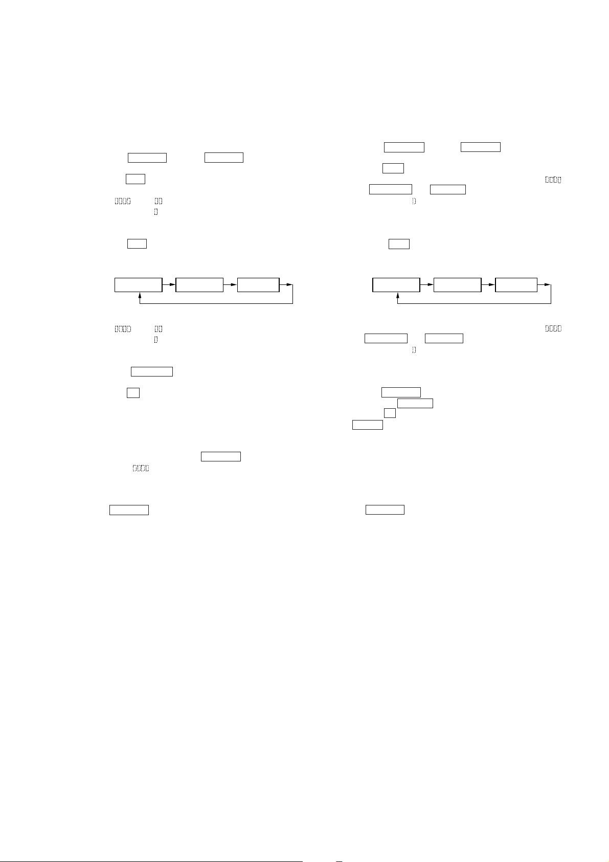
4-6. OPERATING THE CONTINUOUS PLAYBACK
MODE
4-7. OPERATING THE CONTINUOUS RECORDING
MODE
4-6-1. Entering the Continuous Playback Mode
1. Set the MO or CD disc in the unit. (Whichever recordable discs
or discs for playback only are available.)
2. Press the = 0 button or ) + button and display
“CPLAY MODE”.
3. Press the YES button to change the display to “CPLAY MID”.
4. When access completes, the display changes to
“C1=
Note: The numbers “
4-6-2. Changing the Parts to be Played-back
1. Press the YES button during continuous playback to change
the display as below.
2. When access completes, the display changes to
“C1=
Note: The numbers “
4-6-3. Exitting the Continuous Playback Mode
1. Press the EDIT/NO button. The display will change to
“CPLAY MODE”.
2. Press the 6 button and remove the disc.
Notes:
1. The playback start address for IN, MID, and OUT are as follows.
In case you want to display the address of the playback position on the display, press the DISPLAY button and display
“CPLAY (
IN : 40h cluster
MID : 300h cluster
OUT: 700h cluster
2. The EDIT/NO button can be used to stop playing anytime.
AD=
CPLAY MID
AD=
”.
” displayed show you error rates and ADER.
CPLAY OUT CPLAY IN
”.
” displayed show you error rates and ADER.
)”.
4-7-1. Entering the Continuous Recording Mode
1. Set the MO disc in the unit.
2. Press the = 0 button or ) + button and display
“CREC MODE”.
3. Press the YES button to change the display to “CREC MID”.
4. When access completes, the display changes to “CREC (
and, SHUFFLE and REPEAT Turn on.
Note:The numbers “
tion address.
4-7-2. Changing the Parts to be Recorded
1. When the YES button is pressed access is completed, the
display changes as below. (See Note 6.)
CREC MID
2. When access completes, the display changes to “CREC (
and SHUFFLE and REPEAT lightup.
Note:The numbers “
tion address.
4-7-3. Ending the Continuous Recording Mode
1. Press the EDIT/NO button. The display will change to “CREC
MODE” and PRESET goes off.
2. Press the 6 button and remove the disc.
( MONO turns on once and turns off immedia Tely.)
Notes:
1. The recording start address for IN, MID, and OUT are as follows.
IN : 40h cluster
MID : 300h cluster
OUT : 700h cluster
2. The EDIT/NO button can be used to stop recording anytime.
3. During the test mode, the erasing-protection tab will not be
detected. Therefore be careful not to set the continuous recording mode when a disc not to be erased is set in the unit.
4. Do not perform continuous recording for long periods of time
above 5 minutes.
5. During continuous recording, be careful not to apply vibration.
6. After access is completed, the recorded portions cannot be
moved any more.
” displayed shows you the recording posi-
CREC OUT CREC IN
” displayed shows you the recording posi-
)”
)”
– 11 –
4-8. EEP MODE
This mode reads and writes the contents of the non-volatile
memory. It is not used in servicing.
If set accidentally , press the EDIT/NO button immediately to exit
it.
4-9. FUNCTIONS OF OTHER BUTTONS
Table 4-3.
Button
Function
• Sets continuous playback when pressed in
the STOP state. (servo all on)
^
• When pressed during continuous playback,
the tracking and sled servo turns on/off.
p
CHARACTER
SCROLL
r REC
DISPLAY
6
Stop continuous playback and continuous
recording.
The sled moves to the outer circumference
only when this is pressed.
The sled moves to the inner circumference
only when this is pressed.
Turns recording on/off when pressed during
continuous playback.
Switches the diaplay when pressed.
Disc eject
Note: The erasing-protection tab in not detected during the test
mode. Recording will start regardless of the position of
the erasing-protection tab when the r REC button is
pressed.
4-10. TEST MODE DISPLAYS
Each time the DISPLAY button pressed, the display changes in
the following order.
Mode
display
Address display
ADIP address
display
(during MO disc
mode)
Auto gain
display
Error rate
display
SUB Q address
display
(during CD disc
mode)
IVR
display
1. MODE display
Displays “TEMP ADJUST”, “CPLAY MODE”, etc..
2. Error rate display
Error rates are displayed as follows.
C1=
AD=
C1= : Indicates C1 error
AD=: Indicates ADER
3. Address display
Address are displayed as follows.
a= (in MO disc)
h=
s= (during CD disc)
h=
h=: Header address
a=: ADIP address
s=: SUB Q address
Note: “—” is displayed when the address cannot be read.
4. Auto gain display
Auto gain are displayed as follows.
AGF=
T=
F= Focus auto gain acquired value
T= Tracking auto gain acquired value
4-11. MEANINGS OF OTHER DISPLAYS
Table 4-4.
Display
indication
1
MONO
SHUFFLE
TRACK
DISC
PROGRAM
REPEAT
REC LEVEL
OVER
D-IN
A-IN
TOC-EDIT
Light On
CLV locked state
Pit mode
High reflection rate disc
Spindle servo
CLV-S
(pill-in mode)
ABCD adjustment
completed
• Focus auto gain
successful
• Tracking auto gain
successful
Contents
Off
CLV unlocked
state
Groove mode
Low reflection
rete disc
Spindle servo
CLV-A
(playback mode)
ABCD adjustment not yet completed
Blinking
• Focus auto gain
successful
• Tracking auto
gain failed
Note: Auto gain display and IVR display are not used in servicing.
– 12 –
SECTION 5
ELECTRICAL ADJUSTMENTS
5-1. PRECAUTIONS FOR CHECKING LASER DI-
ODE EMISSION
To chec k the emission of the laser diode during adjustments, never
view directly from the top as this may lose your eyesight.
5-2. PRECAUTIONS FOR USE OF OPTICAL
PICK-UP (KMS-260A)
As the laser diode in the optical pick-up is easily damaged by
static electricity, solder the laser tap of the flexible board when
using it.
Before disconnecting the connector, desolder first. Before connecting the connector, be careful not to remove the solder. Also
tale adequate measures to prevent damage by static electricity.
Handle the flexible board with care as it breaks easily.
Pick-up
Laser tap
Optical pick-up flexible board
Flexible board
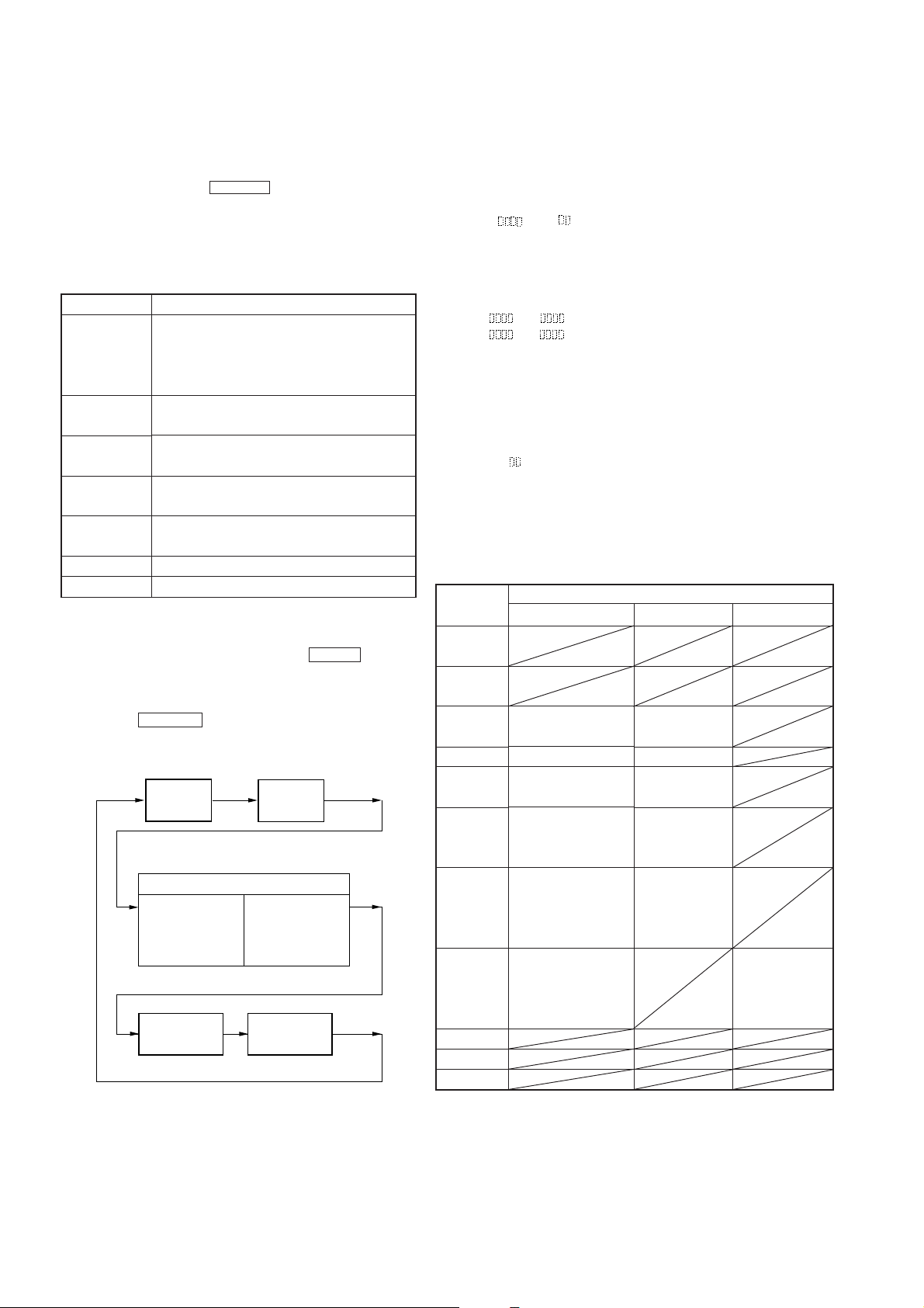
5-3. PRECAUTIONS FOR ADJUSTMENTS
1) When replacing the following parts, perform the adjustments
and checks with ® in the order shown in the following table.
Table 5-1.
Optical
Pick-up
1. Temperature
compensation
offset adjustment
2. Laser power
adjustment
3. Traverse
adjustment
4. Focus bias
adjustment
5. Error rate check
2) Set the test mode when performing adjustments.
After completing the adjustments, exit the test mode.
3) Perform the adjustments in the order shown.
4) Use the following tools and measuring devices.
• Test disc (CD for playback only)
TDYS-1 (part No. 4-963-646-01)
• Laser power meter
LPM-8001 (part No. J-2501-046-A)
• Oscilloscope (Measure after preforming CAL of prove.)
• Digital voltmeter
• Thermometer
5) When observing several signals on the oscilloscope, etc., make
sure that VC and ground do not connect inside the oscilloscope.
(VC and ground will become short-circuited)
IC171 D101 IC101, IC121, IC192
× ®® ®
®®× ®
®®× ®
®®× ®
®®× ®
BD board
5-4. CREATING MO CONTINUOUSLY RECORDED
DISC
* This disc is used in focus bias adjustment and error rate check.
The following describes how to create a MO continuous recording disc.
1. Insert a MO disc (blank disc) commercially available.
2. Press the = 0 button or ) + button and display
“CREC MODE”.
3. Press the YES button and display “CREC MID”.
“CREC (0300)” is displayed for a moment and recording starts.
4. Complete recording within 5 minutes.
5. Press the EDIT/NO button and stop recording.
6. Press the 6 button and remove the MO disc.
The above has been how to create a continuous recording data for
the focus bias adjustment and error rate check.
Note: Be careful not to apply vibration during continuous
recording.
– 13 –
5-5. TEMPERATURE COMPENSATION OFFSET
Optical pick-up
objective lens
laser
power meter
+
–
BD board
digital voltmeter
CN110 pin 5 (I+3V)
CN110 pin
4
(IOP)
ADJUSTMENT
Save the temperature data at that time in the non-volatile memory
as 25°C reference data.
Notes:
1. Usually, do not perform this adjustment.
2. Perform this adjustment in an ambient temperature of 22 °C to
28 °C. Perform it immediately after the power is turned on
when the internal temperature of the unit is the same as the
ambient temperature of 22 °C to 28 °C.
3. When D101 has been replaced, perform this adjustment after
the temperature of this part has become the ambient temperature.
Adjusting Method:
1. Press the = 0 button or ) + button and display
“TEMP ADJUST”.
2. Press the YES b utton and select the “TEMP ADJUST” mode.
3. “TEMP =
played.
4. To save the data, press the YES button.
When not saving the data, press the EDIT/NO button.
5. When the YES button is pressed, “TEMP=
be displayed for some time, followed by “TEMP ADJUST”.
When the EDIT/NO button is pressed, “TEMP ADJUST”
will be displayed immediately.
Specifications:
The temperature should be within “E0-EF”, “F0-FF”, “00-0F”,
“10-1F” and “20-2F”.
” and the current temperature a data will be dis-
SAVE” will
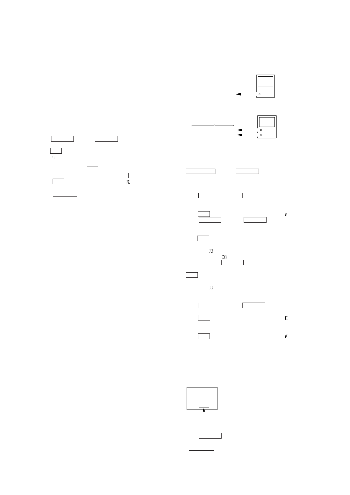
5-6. LASER POWER ADJUSTMENT
Connection:
Adjusting Method:
1. Set the laser power meter on the objective lens of the optical
pick-up. (When it cannot be set properly, press
the CHARACER button or SCROLL button and move the
optical pick-up.)
Connect the digital voltmeter to CN110 pin 5 (I+3V) and
CN110 pin 4 (IOP) of the BD board.
2. Press the = 0 button or ) + button and display
“LDPWR ADJUST”.
(Laser power: for adjustment)
3. Press the YES button and display “LD 0.9 mW $
4. Press the = 0 button or ) + button so that the
reading of the laser power meter becomes 0.82 to 0.91 mW.
Set the range control on the laser power meter to 10 mW, then
press the YES button to save the adjustment result in the nonvolatile memory.
(“LD SAVE $
5. Then “LD 7.0 mW $
” will be displayed for a moment.)
”will be displayed.
6. Press the = 0 button or ) + button so that the
reading of the laser power meter becomes 6.9 to 7.1 mW, press
the YES button and save the adjustment result in the nonvolatile memory.
(“LD SAVE $
” will be displayed for a moment.)
Note: Do not perform the emission with 7.0 mW more than 15
seconds continuously.
7. Press the = 0 button or ) + button and display
“LDPWR CHECK”.
8. Press the YES button and display “LD 0.9 mW $
Check that the reading of the laser power meter becomes 0.80
to 0.96 mW.
9. Press the YES button and display “LD 7.0 mW $
Check that the reading of the laser power meter and digital
voltmeter satisfy the specified value.
”.
”.
”.
Specification:
Laser power meter reading : 7.0 ± 0.2 mW
Digital voltmeter reading : Optical pick-up displayed value ±10%
(Optical pick-up label)
KMS260A
27X40
B0825
lOP=82.5 mA in this case
lOP (mA) = Digital voltmeter reading (mV)/1 (
10. Press the EDIT/NO button and display “LDPWR CHECK”,
and stop the laser emission.
(The EDIT/NO button is effective at all times to stop the
laser emission.)
– 14 –
Ω
)
 Loading...