

Sony MDSLSA-1 Service manual
MDS-LSA1
g
SERVICE MANUAL
US and foreign patents licensed from Dolby Laboratories
Licensin
Corporation.
SPECIFICATIONS
AEP Model
UK Model
Model Name Using Similar Mechanism NEW
MD Mechanism Type MDM-7X2B
Optical Pick-up Type KMS-262A/J1N
System MiniDisc digital audio system
Disc MiniDisc
Laser Semiconductor laser (λ = 780 nm)
Emission duration: continuous
Laser output Less than 44.6 µW
* This output is the value measured
at a distance of 200 mm fr om the
objective lens surface on the Optical
Pick-up Block with 7 mm apertur e.
Laser diode Material: GaAlAs
Revolutions (CLV) 400 rpm to 900 rpm
Error correction ACIRC (Advanced Cr oss Interleave
Reed Solomon Code)
Sampling frequency 44.1 kHz
Coding ATRAC (Adaptive TRansform
Acoustic Coding)/ATRAC3
Modulation system EFM (Eight-to-Fourteen Modulation)
Number of channels 2 stereo channels
Frequency response 5 to 20,000 Hz ±0.3 dB
Signal-to-noise ratio Over 100 dB during playback
Wow and flutter
Below measurable limit
*
Inputs/outputs
i.LINK S200 Jack type: 4-pins to 4-pins
General
Power requirements 230 V AC, 50/60 Hz
Power consumption 18 W
Dimensions (approx.) 430 x 70 x 315 mm (w/h/d) incl.
projecting parts and controls
Mass (approx.) 4.4 kg
Supplied accessories
• i.LINK connecting cable (1)
• Remote commander (remote) (1)
Design and specifications are subject to change without notice.
MINIDISC DECK
1

SELF-DIAGNOSIS FUNCTION
The self-diagnosis function consists of error codes for customers which are displayed automatically when errors occur, and error codes which
show the error history in the test mode during servicing. For details on how to view error codes for the customer, refer to the following box
in the instruction manual. For details on how to check error codes during servicing, refer to the following “Procedure for using the Self-
Diagnosis Function (Error History Display Mode)”.
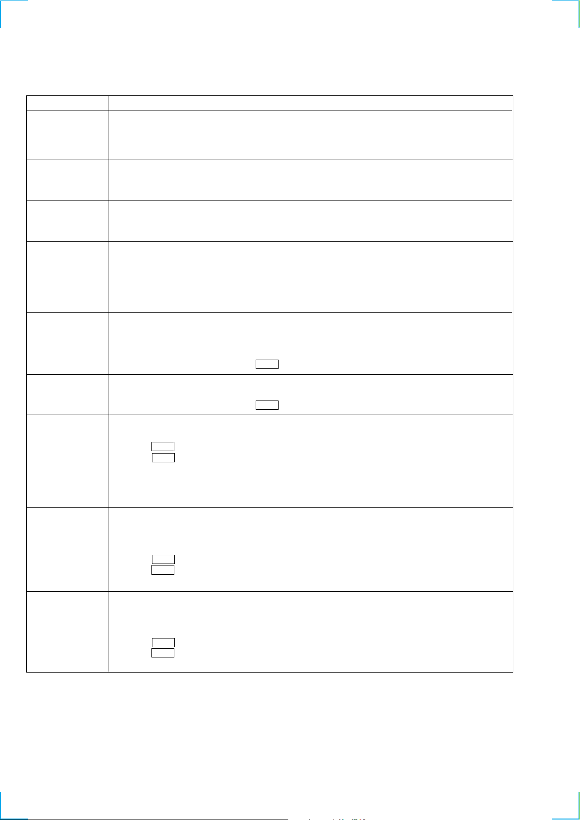
Self-Diagnosis Function
The deck’s self-diagnosis function automatically checks the condition of the MD deck when an error occurs, then issues a
code and an error message on the display . If the code and message alternate, find them in the following table and perform
the indicated countermeasur e. Should the problem persist, consult your nearest Sony dealer .
Code/Message Cause/Remedy
C11/Pr otected The inserted MD is recor d-protected.
C12/Cannot Copy An attempt was made to play a disc that is not compatible with this deck (MD data disc, etc.).
C13/REC Error The recor ding was not made properly .
C13/Read Error The deck could not read the TOC on the MD properly.
C14/T oc Err or The deck could not read the TOC on the MD properly.
C41/Cannot Copy The digitally dubbed material cannot be recorded digitally (page 14).
C71/Din Unlock The sporadic appearance of this message is caused by the digital signal being recor ded. This will not af fect
C78:03/LOOP CONNECT The i.LINK connection is looped.
C78:04/NO SIGNAL The selected component is turned on, but no signal is not output from the component.
C78:11/C78:12/CANNOT LINC
C78:15/BUS FULL The signal bus within the i.LINK configuration is full and no more signals can be output from the deck.
C78:21/NO SIGNAL The deck and the selected component are connected correctly, but no signal from the component is input to
C78:22/NO SIGNAL The format of the input signal is not supported.
C78:23/NO SIGNAL The selected component is not turned on.
C78:31/NO SIGNAL The communication between the deck and the selected component is unstable. Or , the format of the input
C78:32/NEW CONNECT While recor ding, a new component is connected within the i.LINK configuration, or a mains lead or an
E0001/MEMORY NG Ther e is an error in the internal data that the deck needs in order to operate.
E0101/LASER NG Ther e is a problem with the optical pick-up.
, Take out the MD and close the recor d-protect slot (page 13).
, Replace the disc.
, Set the deck in a stable surface, and repeat the recor ding procedure.
The inserted MD is dirty (with smudges, fingerprints, etc.), scratched, or substandard in quality.
, Replace the disc and repeat the recording procedur e.
, Take out the MD and insert it again.
, Insert another disc.
, If possible, erase all the tracks on the MD (page 29).
the recor ding.
While recor ding from a digital component connected through the i.LINK S200 connector , the digital
connecting cable was unplugged or the digital component turned off.
, Connect the cable or turn the digital component back on.
, Check the connection (see page 39).
.
, Check the selected component.
The deck cannot establish a LINC with a component because of an existing LINC between the deck and
another component.
, Cancel the LINC between the deck and the other component.
the deck.
, Check the selected component.
, Verify that the component is on.
signal is not supported.
, Check the condition and the signal format of the selected component.
i.LINK connecting cable of the component within the configuration is connected or disconnected.
, Do not connect or disconnect any mains leads or i.LINK connecting cables during recording. If you do,
recording may not be done corr ectly.
, Consult you nearest Sony dealer.
, Consult you nearest Sony dealer
2

Procedure for using the Self-Diagnosis Function (Error History Display Mode).
Note: Perform the self-diagnosis function in the “error history display mode” in the test mode. The following describes the least required
procedure. Be careful not to enter other modes by mistake. If you set other modes accidentally, press the POWER “X2” button to
exit the mode.
1. While pressing the . button and x button, connect the power plug to the outlet, and release the . button and x button.
When the test mode is set, “[Check]” will be displayed.
2. Press the . or > button and when “[Service]” is displayed, press the 7 button.
3. Press the . or > button and display “Err Display”.
4. Pressing the 7 button sets the error history mode and displays “op rec tm”.
5. Select the contents to be displayed or executed using the . button.
6. Pressing the POWER button will display or execute the contents selected.
7. Pressing the POWER button another time returns to step 4.
8. Pressing the x button displays “Err Display” and exits the error history mode.
9. To exit the test mode, press the POWER “X2” button. The unit sets into the STANDBY state, the disc is ejected, and the test mode ends.
10.If the unit fails to enter STANDBY mode, remove the AC cord from its socket, insert the AC cord into the socket again, turn on the power,
and then check to make sure that the unit has exited from test mode.
NOTE
• The MDS-LSA1 is designed so that a number of functions which may be performed in test mode may be performed by clicking a single
button.
Switching between functions
Pressing the INPUT button causes the display to change as indicated below.
Hidden t “X2”
↑
The functions performed by each button change in accordance with the DISPLAY mode.
Note that the following notation is used herein:
POWER ............. Press the POWER button when HIDDEN.
POWER “X2” .... Press the POWER button while “X2” is lit.
3
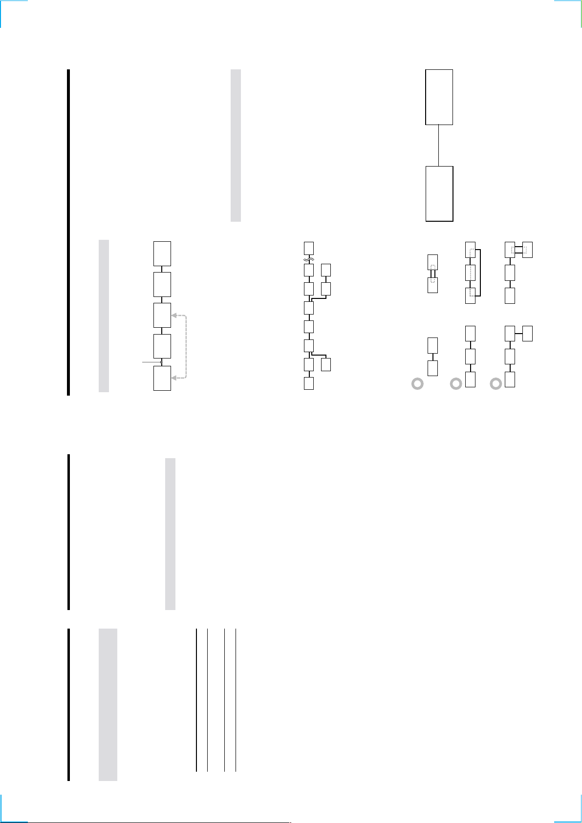
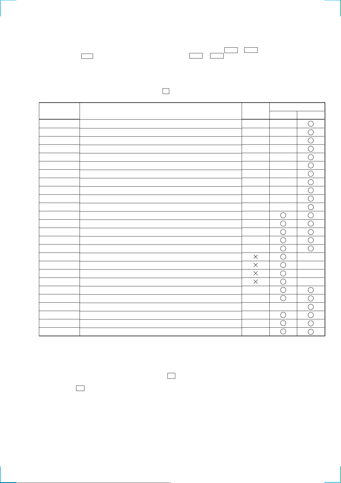
ITEMS OF ERROR HISTORY MODE ITEMS AND CONTENTS
Selecting the Test Mode
Display
op rec tm
op play tm
spdl rp tm
retry err
total err
err history
retry adrs
History
Displays the total recording time.
When the total recording time is more than 1 minute, displays the hour and minute
When less than 1 minute, displays “Under 1 min”
The display time is the time the laser is set to high power, which is about 1/4 of the actual recording time.
Displays the total playback time.
When the total playback time is more than 1 minute, displays the hour and minute
When less than 1 minute, displays “Under 1 min”
Displays the total rotating time of the spindle motor.
When the total rotating time is more than 1 minute, displays the hour and minute
When less than 1 minute, displays “Under 1 min”
Displays the total number of retry errors during recording and playback
Displays “r xx p yy”. xx is the number of errors during recording. yy is the number of errors during playback.
This is displayed in hexadecimal from 00 to FF.
Displays the total number of errors
Displays “total xx”. This is displayed in hexadecimal from 00 to FF.
Displays the past ten errors.
Displays “0x ErrCd@@”.
X is the history number. The younger the number, the more recent is the history (00 is the latest). @@ is the error
code.
Select the error history number using the . button.
Displays the past five retry addresses.
Displays “xx ADRS yyyy”, xx is the history number, yyyy is the cluster with the retry error.
Select the error history number using the . button.
er refresh
op change
spdl change
Mode for erasing the error and retry address histories
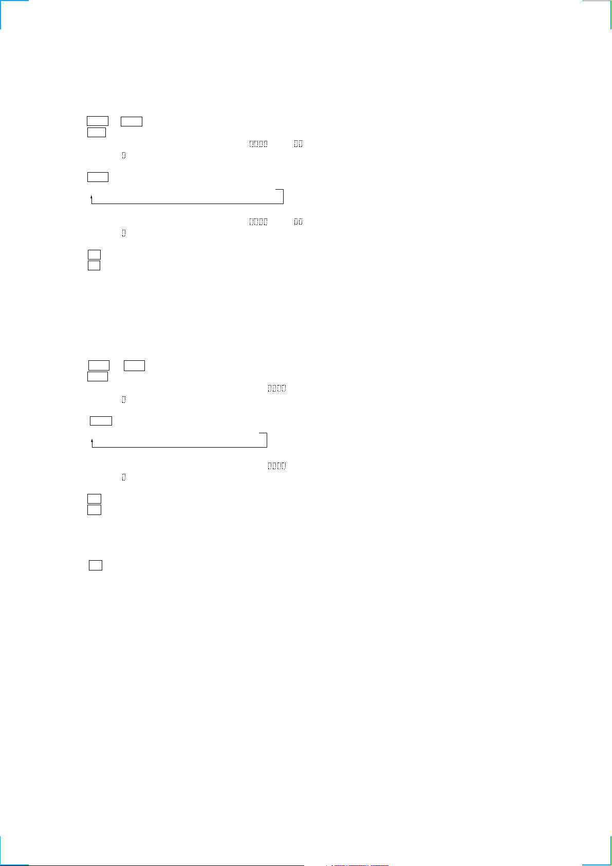
Procedure
1. Press the . button when displayed as “er refresh”.
2. Press the 7 button when the display changes to “er refresh?”.
When “complete!” is displayed, it means erasure has completed.
Be sure to check the following after executing this mode.
*Data has been erased.
*Perform recording and playback, and check that the mechanism is normal.
Mode for erasing the total time of op rec tm, op play tm.
These histories are based on the time of replacement of the optical pick-up. If the optical pick-up has been replaced,
perform this procedure and erase the history.
Procedure
1. Press the . button when displayed as “op change”.
2. Press the 7 button when the display changes to “op change?”.
When “Complete!” is displayed, it means erasure has completed.
Mode for erasing the total spdl rp tm time
These histories are based on the time of replacement of the spindle motor. If the spindle motor has been replaced,
perform this procedure and erase the history.
Procedure
1. Press the . button when displayed as “spdl change”
2. Press the 7 button when the display changes to “spdl change?”
When “Complete!” is displayed, it means erasure has completed.
4

Table of Error Codes
TABLE OF CONTENTS
Error Code
10
12
20
21
22
23
24
30
31
40
41
42
43
50
51
Description
Could not load
Loading switches combined incorrectly
Timed out without reading the top of PTOC
Could read top of PTOC, but detected error
Timed out without accessing UTOC
Timed out without reading UTOC
Error in UTOC
Could not start playback
Error in sector
Retry cause generated during normal recording
Retried in DRAM overflow
Retry occurred during TOC writing
Retry aborted during S.F editing
Other than access processing, and could not read address.
Focus NG occurred and overran.
1. SERVICING NOTES ............................................. 6
2. GENERAL ........................................................................ 12
3. DISASSEMBLY
3-1. Case (Top) ........................................................................... 17
3-2. MD Mechanism Deck ......................................................... 18
3-3. Base (Front) Assy, Panel ..................................................... 18
3-4. Clip Board and Main Board ................................................ 19
3-5. Trans Board ......................................................................... 19
3-6. Holder Assy ......................................................................... 20
3-7. Over Write Head ................................................................. 20
3-8. Optical pick-up (MD) (KMS-262A/J1N) ............................ 21
3-9. BD Board ............................................................................ 21
4. TEST MODE ..................................................................... 22
5. ELECTRICAL ADJUSTMENTS ............................... 30
6. DIAGRAMS
6-1. Circuit Boards Location ...................................................... 41
6-2. Block Diagrams
• BD Section ....................................................................... 42
• Main Section .................................................................... 43
6-3. Printed Wiring Board – BD Section – ................................. 45
6-4. Schematic Diagram – BD Section (1/2) – ........................... 46
6-5. Schematic Diagram – BD Section (2/2) – ........................... 47
6-6. Printed Wiring Board – Main Section (Side A) – ............... 48
6-7. Printed Wiring Board – Main Section (Side B) – ............... 49
6-8. Schematic Diagram – Main Section (1/3) – ........................ 50
6-9. Schematic Diagram – Main Section (2/3) – ........................ 51
6-10. Schematic Diagram – Main Section (3/3) – ..................... 52
6-11. Printed Wiring Board – Power Section – ......................... 53
6-12. Printed Wiring Board – Panel Section – ........................... 54
6-13. Schematic Diagram – Panel Section – ............................. 55
6-14. IC Block Diagrams ........................................................... 56
6-15. IC Pin Functions ............................................................... 59
7. EXPLODED VIEWS
7-1. Panel Section ....................................................................... 70
7-2. Chassis Section ................................................................... 71
7-3. MD Mechanism Section-1 (MDM-7X2B) .......................... 72
7-4. MD Mechanism Section-2 (MDM-7X2B) .......................... 73
8. ELECTRICAL PARTS LIST ........................................ 74
5
SECTION 1
SERVICE NOTES
NOTES ON HANDLING THE OPTICAL PICK-UP
BLOCK OR BASE UNIT
The laser diode in the optical pick-up block may suffer electrostatic
break-down because of the potential difference generated by the
charged electrostatic load, etc. on clothing and the human body.
During repair, pay attention to electrostatic break-down and also
use the procedure in the printed matter which is included in the
repair parts.
The flexible board is easily damaged and should be handled with
care.
NOTES ON LASER DIODE EMISSION CHECK
Never look into the laser diode emission from right above when
checking it for adjustment. It is feared that you will lose your sight.
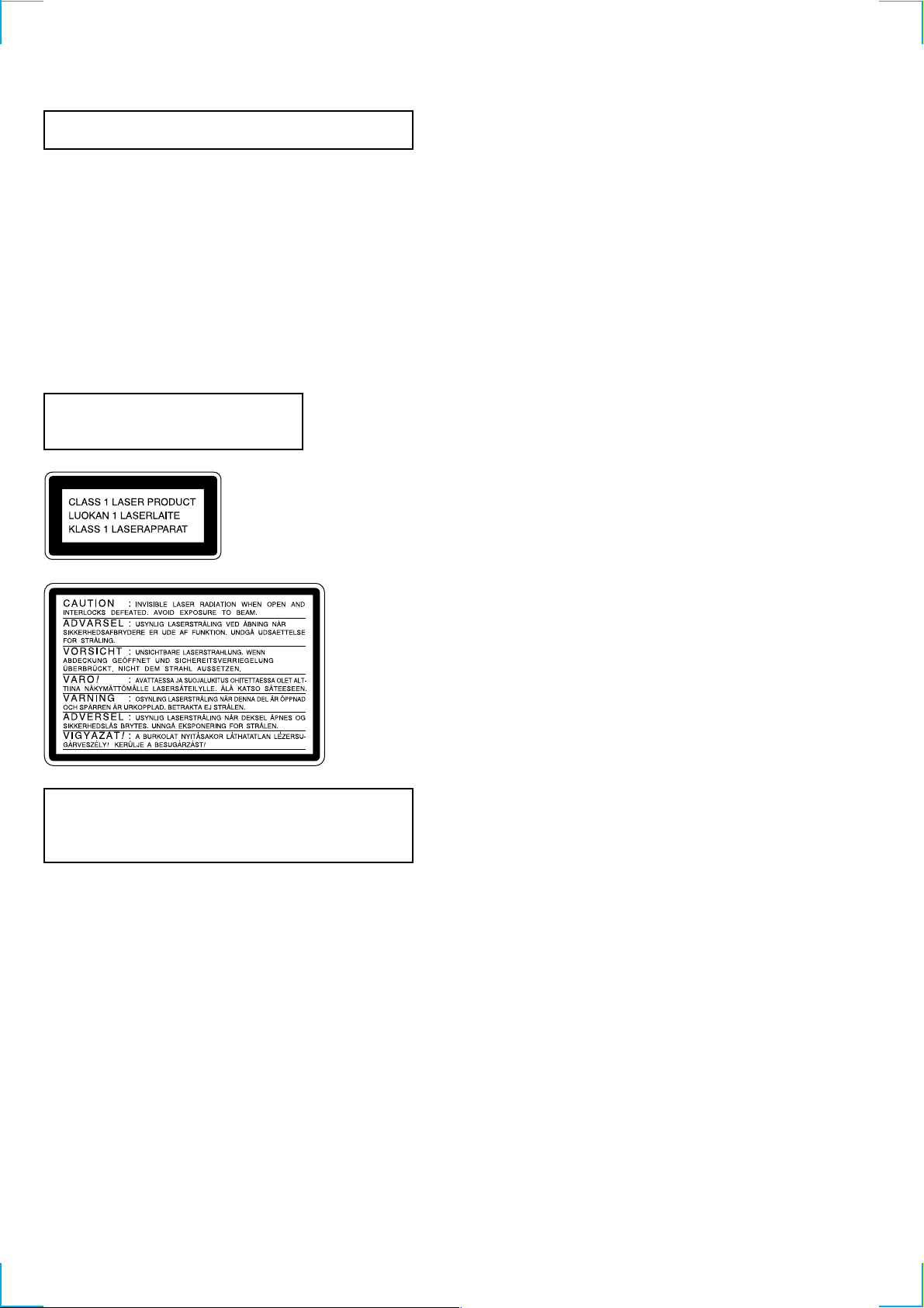
Laser component in this product is capable
of emitting radiation exceeding the limit for
Class 1.
This appliance is classified as a
CLASS 1 LASER product. The
CLASS 1 LASER PRODUCT
MARKING is located on the
rear exterior.
Notes on chip component replacement
• Never reuse a disconnected chip component.
• Notice that the minus side of a tantalum capacitor may be
damaged by heat.
Flexible Circuit Board Repairing
• Keep the temperature of soldering iron around 270˚C
during repairing.
• Do not touch the soldering iron on the same conductor of the
circuit board (within 3 times).
• Be careful not to apply force on the conductor when soldering
or unsoldering.
This caution
label is located
inside the unit.
CAUTION
Use of controls or adjustments or performance of procedures
other than those specified herein may result in hazardous radiation exposure.
SAFETY-RELATED COMPONENT WARNING!!
COMPONENTS IDENTIFIED BY MARK 0 OR DOTTED LINE WITH
MARK 0 ON THE SCHEMATIC DIAGRAMS AND IN THE PARTS
LIST ARE CRITICAL TO SAFE OPERATION. REPLACE THESE
COMPONENTS WITH SONY PARTS WHOSE PART NUMBERS
APPEAR AS SHOWN IN THIS MANUAL OR IN SUPPLEMENTS
PUBLISHED BY SONY.
6
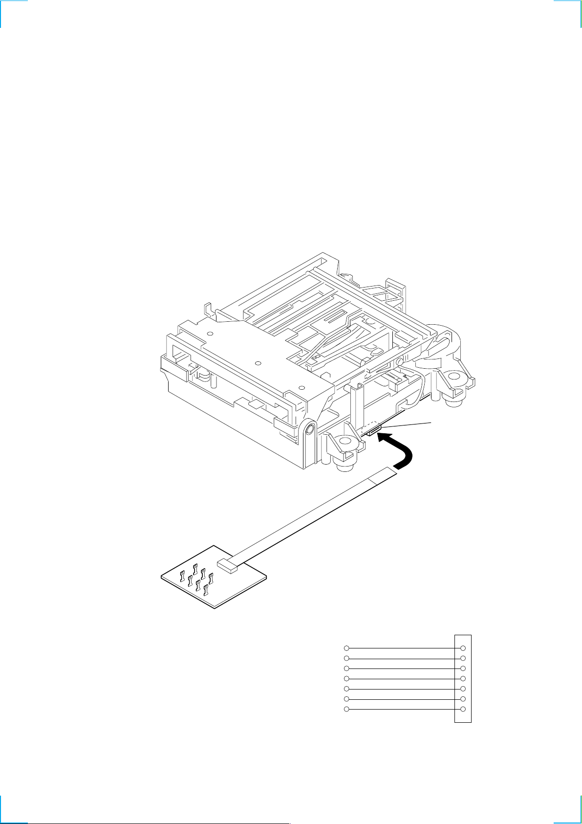
JIG FOR CHECKING BD BOARD WAVEFORM
I+3V
IOP
GND
TE
FE
VC
RF
I+3V
IOP
GND
TE
FE
VC
RF
1
7
for
MDM-7X2B
The special jig (J-2501-196-A) is useful for checking the waveform of the BD board. The names of terminals and the checking items to be
performed are shown as follows.
GND : Ground
I+3V : For measuring IOP (Check the deterioration of the optical pick-up laser)
IOP : For measuring IOP (Check the deterioration of the optical pick-up laser)
TE : TRK error signal (Traverse adjustment)
VC : Reference level for checking the signal
RF : RF signal (Check jitter)
FE : Focus error signal
I+3V
GND
FE
CN105
IOP
TE
VC
RF
7

IOP DATA RECORDING AND DISPLAY WHEN OPTICAL PICK-UP AND NON-VOLATILE MEMORY (IC195 OF
BD BOARD) ARE REPLACED
The Iop value labeled on the optical pick-up can be recorded in the non-volatile memory. By recording the value, it will eliminate the need
to look at the value on the label of the optical pick-up. When replacing the optical pick-up or non-volatile memory (IC195 of BD board),
record the Iop value on the optical pick-up according to the following procedure.
Record Precedure:
1. While pressing the . button and x button, connect the power plug to the outlet, and release the . button and x button.
2. Press the . or > button to display “[Service]”, and press the 7 button.
3. Press the . or > button to display “Iop Write” , and press the 7 button.
4. The display becomes “Ref=@@@.@” (@ is an arbitrary number) and the numbers which can be changed will blink.
5. Input the Iop value written on the optical pick-up.
To select the number : Press the . or > button.
To select the digit : Press the POWER button.
6. When the 7 button is pressed, the display becomes “Measu=@@@.@” (@ is an arbitrary number).
7. As the adjustment results are recorded for the 6 value. Leave it as it is and press the 7 button.
8. “Complete!” will be displayed momentarily. The value will be recorded in the non-volatile memory and the display will become “Iop
Write” .
9. Press the POWER “X2” button to complete.
Display Precedure:
1. While pressing the . button and x button, connect the power plug to the outlet, and release the . button and x button.
2. Press the . or > button to display “[Service]”, and press the 7 button.
3. Press the . or > button to display “Iop Read” , and press the 7 button.
4. “@@.@/##.#” is displayed and the recorded contents are displayed.
@@.@ : indicates the Iop value labeled on the optical pick-up.
##.# : indicates the Iop value after adjustment.
5. To end, press the x button to display “Iop Read”. Then press the POWER “X2” button.
8
CHECKS PRIOR TO PARTS REPLACEMENT AND ADJUSTMENTS
Before performing repairs, perform the following checks to determine the faulty locations up to a certain extent.
Details of the procedures are described in “5 Electrical Adjustments”.
• 5-6-2. Laser power check (see page 33)
• 5-6-3. Iop Compare (see page 33)
• 5-6-4. Auto Check (see page 34)
Note:
The criteria for determination above is intended merely to determine if satisfactory or not, and does not serve as the specified value for
adjustments.
When performing adjustments, use the specified values for adjustments.
FORCED RESET
The system microprocessor can be reset in the following procedure.
Use these procedure when the unit cannot be operated normally due to the overrunning of the microprocessor, etc.
Procedure :
1. Disconnect the short-circuit pin of CN201.
2. Disconnect the AC outlet.
3. After some time, connect AC power plug to the AC outlet again.
4. Connect the short-circuit pin of CN201.
[MAIN BOARD] (SIDE A)
CN201
9
RETRY CAUSE DISPLAY MODE
• In this test mode, the causes for retry of the unit during recording can be displayed on the fluorescent indicator tube. During playback, the
“track mode” for obtaining track information will be set.
This is useful for locating the faulty part of the unit.
• The following will be displayed :
During recording and stop : Retry cause, number of retries, and number of retry errors.
During playback : Information such as type of disc played, part played, copyright.
These are displayed in hexadecimal.
Procedure:
1. Press the x button continuously for about 10 seconds.
2. When the mode is set, “RTs 00c 00e 00” is displayed.
3. Set a recortable disc in the unit.
4. Press the z REC button to start recording. Then press the 7 button and start recording.
5. To check the “track mode”, press the 7 button to start play.
6. To exit the test mode, disconnect the power plug from the outlet. If the test mode cannot be exited, refer to “Forced Reset” on page 9.
Fig. 1 Reading the Test Mode Display
(During recording and stop)
(During playback)
RTs@@c##e**
Fluorescent display tube display
@@ : Cause of retry
## : Number of retries
** : Number of retry errors
Fig. 2 Reading the Test Mode Display
Reading the Retry Cause Display
Higher Bits Lower Bits
Hexadecimal
Bit
Binary
84218421
b7 b6 b5 b4 b3 b2 b1 b0
00000001
00000010
00000100
00001000
00010000
00100000
01000000
10000000
Hexa-
decimal
01
02
04
08
10
20
40
80
@@ ###** $$
Fluorescent display tube display
@@ : Parts No. (name of area named on TOC)
### : Cluster
** : Sector
$$ : Track mode (Track information such as copyright infor-
Cause of Retry Occurring conditions
shock
ader5
Discontinuous address
DIN unlock
FCS incorrect
IVR rec error
CLV unlock
Access fault
} Address (Physical address on disc)
mation of each part)
When track jump (shock) is detected
When ADER was counted more than five times continu-
ously
When ADIP address is not continuous
When DIN unlock is detected
When not in focus
When ABCD signal level exceeds the specified range
When CLV is unlocked
When access operation is not performed normally
Reading the Display:
Convert the hexadecimal display into binary display. If more than two causes, they will be added.
Example
When 42 is displayed:
Higher bit : 4 = 0100 t b6
Lower bit : 2 = 0010 t b1
In this case, the retry cause is combined of “CLV unlock” and “ader5”.
When A2 is displayed:
Higher bit : A = 1010 t b7+b5
Lower bit : 2 = 0010 t b1
The retry cause in this case is combined of “Access fault”, “IVR rec error”, and “ader5”.
10
Reading the Track Mode Display
Higher Bits Lower Bits
Hexadecimal
Bit
Binary
Reading the Display:
Convert the hexadecimal display into binary display. If more than two causes, they will be added.
Example When 84 is displayed:
Higher bit : 8 = 1000 t b7
Lower bit : 4 = 0100 t b2
In this case, as b2 and b7 are 1 and others are 0, it can be determined that the retry cause is combined of “Emphasis OFF”, “Monaural”,
“Original”, “Copyright exists”, and “Write allowed”.
Example When 07 is displayed:
Higher bit : 0 = 1000 t All 0
Lower bit : 7 = 0111 t b0+b1+b2
In this case, as b0, b1, and b2 are 1 and others are 0, it can be determined that the retry cause is combined of “Emphasis ON”, “Stereo”,
“Original”, “Copyright exists”, and “Write prohibited”.
84218421
b7 b6 b5 b4 b3 b2 b1 b0
00000001
00000010
00000100
00001000
00010000
00100000
01000000
10000000
Hexa-
decimal
01
02
04
08
10
20
40
80
When 0 When 1
Emphasis OFF
Monaural
This is 2-bit display. Normally 01.
01:Normal audio. Others:Invalid
Audio (Normal)
Original
Copyright
Write prohibited
Details
Emphasis ON
Stereo
Invalid
Digital copy
No copyright
Write allowed
Hexadecimal t Binary Conversion Table
Hexadecimal Binary Hexadecimal Binary
0
1
2
3
4
5
6
7
0000
0001
0010
0011
0100
0101
0110
0111
8
9
A
B
C
D
E
F
1000
1001
1010
1011
1100
1101
1110
1111
11
z
x
0qa
. >
HIGH SPEEDCD SYNCHROREC
A
89
DISPLAY REC MODE
456 7
INPUT
qf qd qs
qh qg
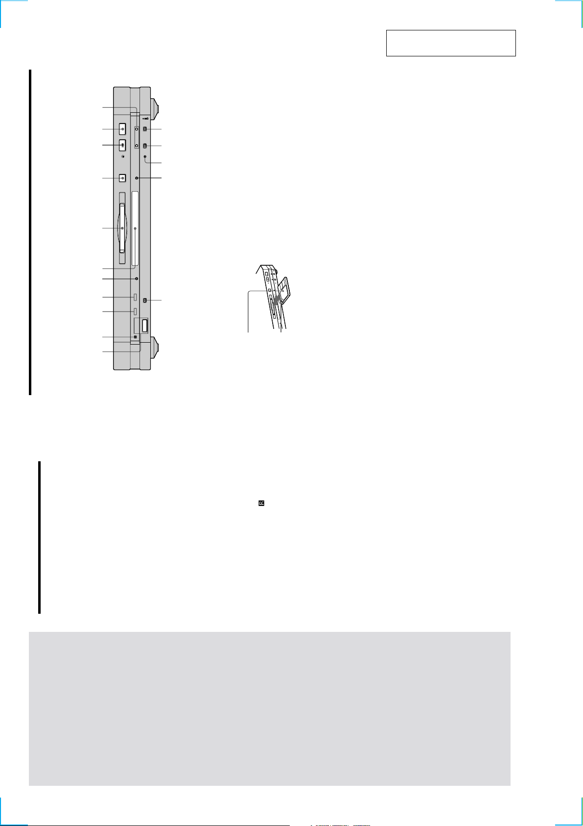
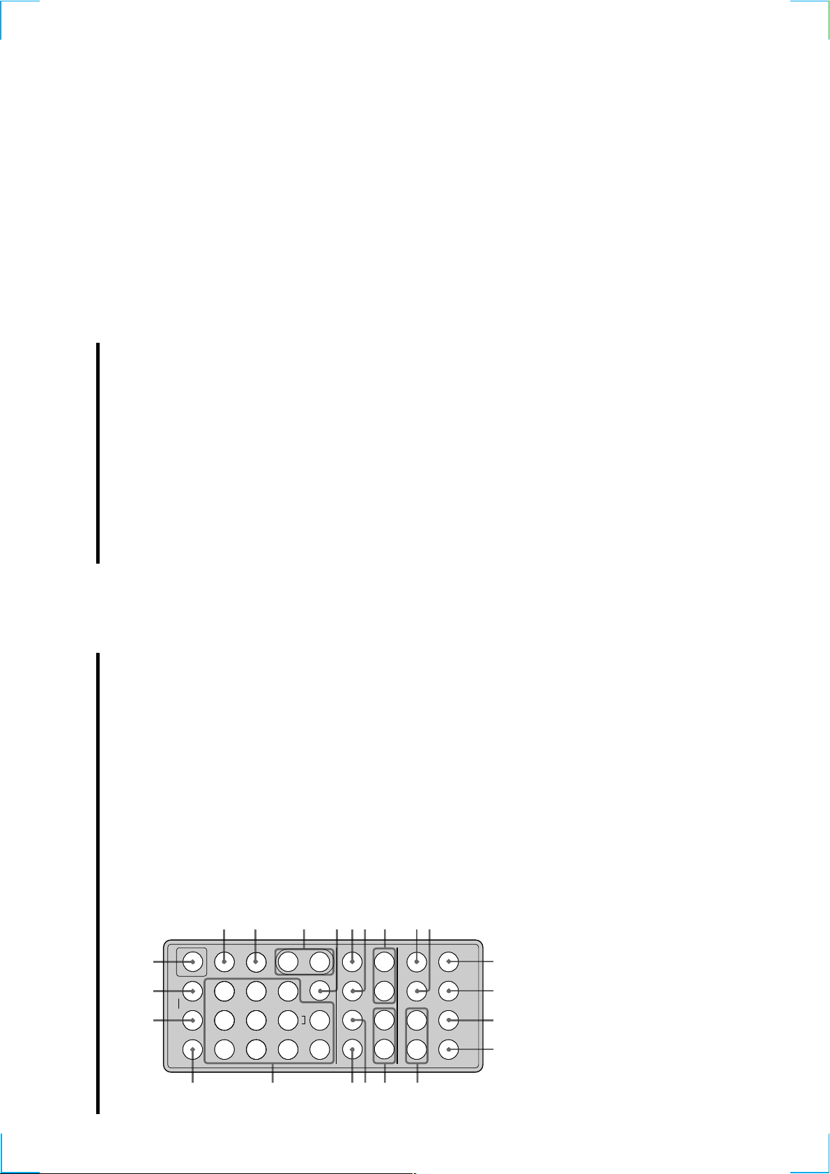
qf HIGH SPEED indicator (20)
SECTION 2
GENERAL
Lights up when the deck is in High-speed CD
Synchr o-r ecor ding mode.
Press to select one of the following four r ecording
qg REC MODE button (15)
This section is extracted from
instruction manual.
GB
5
in the display window of the component. Press the
modes: MONO mode (monaural recor ding), stereo
mode (ster eo recor ding), LP2 mode (2 times long
recor ding), and LP4 mode (4 times long recor ding).
Press once to display the selected pr ogramme source.
qh INPUT button (12)
z
x
>
.
A
button again to switch to another programme source.
If the pr ogramme sour ce is either the STR-LSA1 or the
CDP-LSA1, “N N n n” appears momentarily
Front Panel Parts
Descriptions
STANDBY LP H.A.T.S
23
1
?/1
With the arrow
pointing towards
6 Display window (8, 16, 32, 35)
Shows various information. For details, see “Display
Window Descriptions” on page 8.
Press to turn on the deck. When you turn on the deck,
1 ~/1 (power) switch (12, 21)
Insert the MD as illustrated below .
7 MD insertion slot (12, 21)
the STANDBY indicator turns off. When you press the
switch again, the deck turns off and the indicator
With the labelled
side up
) for r emote
lights up.
Point the remote towar ds this sensor (
2 Remote sensor
operations.
3 LP indicator (15)
Lights up when LP2 or LP4 mode is selected, or when
the deck
a track recor ded in LP2 or LP4 mode is being played.
Press to eject the MD.
8 A button (12, 21)
Lights up when the H.A.T.S. function is activated on
the receiver .
4 H.A.T.S. indicator
• P ress when the deck is stopped to start play .
9 HX button (12, 19, 21, 22)
What is the H.A.T.S. function?
z
resume play or r ecor ding.
• P ress during playback to pause play .
• P ress during recor ding to pause recording.
• P ress during playback pause or recording pause to
q; x button (12, 20, 21)
The H.A.T.S. (High-quality digital Audio Transmission
System) function on the receiver causes digital audio signals
output from an MD deck or the recording sour ce (e.g., a CD
player) to be momentarily stor ed in a buffer in the receiver
prior to output. This reduces jitter that sometimes occurs
during digital audio transmission.
Press to stop play or r ecording, or cancel the selected
operation.
5 DISPLAY button (9, 13, 16, 20, 21)
qa ./> buttons (12, 15, 16, 19, 21, 22)
information.
• P ress when the deck is stopped to display disc
Press to locate tracks or select a menu item and a
setting value.
Press to r ecor d on the MD or mark track numbers.
Press to start CD Synchr o-recor ding.
qs REC z button (12, 17)
qd CD SYNCHRO button (19)
ding level.
track being recor ded or recor dable time on the MD.
current track.
of the track curr ently being played in the
pr ogramme.
• P ress during recor ding to display information on the
• P ress during play to display information on the
• P ress during Programme Play to display the number
the recor
• Pr ess during recording or recording pause to adjust
Location and
Function of
Parts
12
This chapter tells you about the
location and function of the various
buttons and contr ols on the front
panel and the supplied remote.
Further details are pr ovided on the
pages indicated in the parentheses.
It also tells you about the information
that appears in the display window .
GB
4
GB
w;
2
wa ws 1
3
4
567
8
9
0
ql
qkqjqh
qg
qdqf qs qa
?/1
.>m M
NX
xz
789
>10
10
/0
123
456
PLAY MODE
ABC
,
–/, DEF DISPLAY
JKLGHI MNO
TUVPQRS WXYZ
SCROLL
YES
MENU/NO
FADER
REC MODE
CLEAR
NAME EDIT/
SELECT
M.SYNC
T.REC
INPUT LEVEL
REPEAT
CLEAR
MD
A
y
B
–
+
1 ~/1 (power) switch (12, 21)
Press to turn on the deck. When you turn on the deck,
the STANDBY indicator on the deck turns off. When
you pr ess the switch again, the deck turns off and the
indicator lights up.
2 DISPLAY button (9, 13, 16, 20, 21, 24)
Press to select the information to be displayed in the
window .
3 SCROLL button (21)
Press to scr oll the name of a track or MD.
4 LEVEL +/– buttons (16)
Press to adjust the recor ding level.
5 INPUT button (12)
Use to select the pr ogramme sour ce to be recorded.
6 z button (12, 17, 19)
Press to r ecor d on the MD or mark track numbers.
7 x button (12, 20, 21)
Press to stop play or recor ding, or cancel the selected
operation.
8 m/M buttons (22, 23, 29, 30, 32)
Press to locate a portion within a track, change the
contents of a pr ogramme, or shift the cursor to the
right.
9 REC MODE button (15)
Press to select one kf the following four recor ding
modes: MONO mode (monaural recor ding), ster eo
mode (ster eo recor ding), LP2 mode (2 times long
recor ding), and LP4 mode (4 times long recor ding).
q; FADER button (36)
Press to perform Fade-in Recor ding or Fade-out
Recor ding.
qa T.REC button (18)
Press to start Time Machine Recording.
qs MUSIC SYNC button (19)
Press to start Music Synchr o-recor ding.
qd CLEAR button (24, 33)
Press to erase a track in the pr ogramme or erase a
character .
qf NAME EDIT/SELECT button (32, 33)
Press to add the name or change the name of a track or
an MD, or to select the type of characters to be input.
GB
7
.
Press to display “Edit Menu” or “Setup Menu.”
YES button (15-17, 19, 24-26, 28-38)
Press to carry out the selected operation.
qg MENU/NO button (15-19, 25, 26, 28-38)
Press to locate tracks, select a menu item and a setting
qh ./> buttons (12, 15-19, 21, 22, 24-26, 28-38)
value, or select the character to be input.
qj X button (12, 20, 21)
Press to pause play or r ecording. Press again to
resume play or recording.
Press to start play .
qk N button (12, 19, 21, 22, 24)
Press to input letters or numbers.
ql Letter/number buttons (22, 24, 32)
Press to select Shuf fle Play or Pr ogramme Play .
w; PLAY MODE button (24)
wa REPEAT CLEAR button (23)
ws AyB button (23)
Press to select Repeat A-B Play
pr ess to resume normal play .
• P ress to play tracks r epeatedly.
• When Repeat All Play or Repeat 1 Play is selected,
13
Mains lead
GB
11
CD
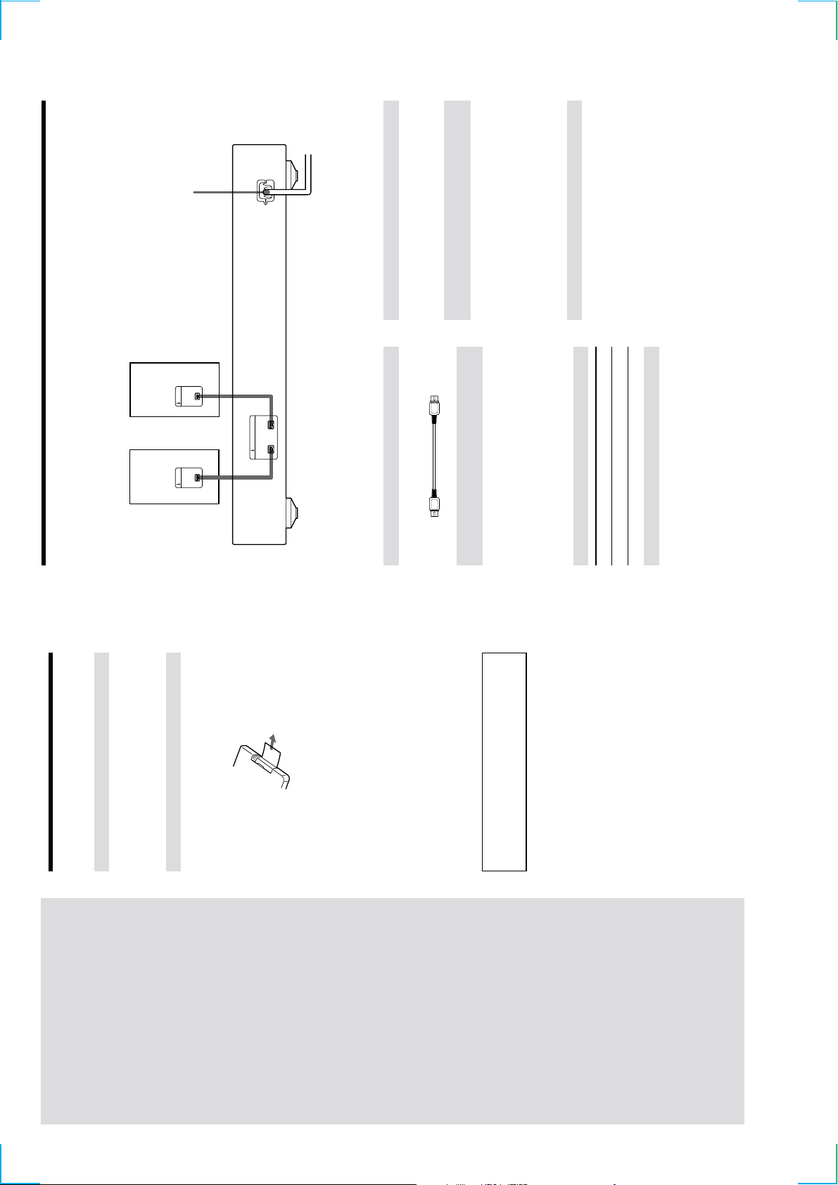
Hooking Up the i.LINK Components
About optional i.LINK connecting cables
About i.LINK components to be used in
(4 pins-4 pins).
combination with the MD deck
The following i.LINK components can be used with the
Be sure to use the Sony i.LINK S200 connecting cables
MD deck:
• STR-LSA1 r eceiver
• CDP-LSA1 CD Player
For general information about i.LINK
z
Connecting the mains lead
See “About i.LINK” on page 38.
Connect the mains lead of the deck to a wall outlet.
Note
If you use a timer, connect the mains lead to the outlet of the
timer .
*
player,
etc.
i.LINK S200
v v
i.LINK i.LINK
*
Receiver,
etc.
You can connect the i.LINK components to either i.LINK S200 connector
*
Required cords
i.LINK connecting cables (2) (only one supplied)
Things you should keep in mind while
hooking up the system
any connections.
• Turn off the power to all components befor e making
• Do not connect any mains lead until all the connections
are completed.
noise.
• Be sur e the connections ar e firm to pr event hum and
Jacks for connecting i.LINK components
Connect an To the
Note on i.LINK component hookups
eceiver or CD player , etc. i.LINK S200 connector
If a metal object should fall into the i.LINK S200
connector , short-cir cuiting may occur and damage the
components.
Before You Start the
Hookup
Getting
14
Checking the supplied accessories
This MD deck comes with the following items:
• i.LINK connecting cable (1)
Started
This chapter pr ovides information on
• Remote commander (remote) (1)
the supplied accessories, things you
should keep in mind while hooking
Before using the supplied remote
The supplied r emote alr eady contains a battery . Before
using the remote, pull out the insulating sheet to allow the
up the system, and how to connect
i.LINK components to the MD deck.
Be sur e to r ead this chapter
power to flow from the battery .
connect anything to the deck.
thor oughly befor e you actually
If you don’t use the remote for an extended period of time,
remove the battery to avoid possible damage fr om battery
leakage and corrosion.
When to replace the battery
z
Under normal conditions, the battery should last for about six
months. When the remote no longer operates the deck, replace
To avoid battery leakage
the battery with new kne.
Notes on lithium battery
Should the battery be swallowed, immediately consult a doctor .
battery .
• Keep the lithium battery out of the r each of the children.
• Wipe the battery with a dry cloth to assur e a good contact.
• Be sur e to observe the corr ect polarity when inserting the
short-cir cuit may occur.
WARNING
Battery may explode if mistr eated.
• Do not hold the battery with metallic tweezers, otherwise a
Do not rechar ge, disassemble, or dispose of in fire.
GB
10
B
transfer signals when they ar e turned of f. Refer to the
operation manual of each component to be connected before
you hook them up.
The use of i.LINK cables to connect i.LINK components as
• The maximum transmission rate of an i.LINK component is
shown below is called a “daisy chain” configuration.
i.LINK connecting cable
printed near its i.LINK connector . The indications S100, S200,
Notes
• Some i.LINK components (such as personal computers) do not
i.LINK connections
and S400 refer to maximum transmission rates of 100, 200, or
400 Mbps*, respectively . The actual transmission rate may be
faster or slower , depending on the dif ferences in transmission
i.LINK
component
i.LINK
component
i.LINK
component
i.LINK
component
i.LINK
component
What is Mbps?
rates and specifications among the connected components.
z
“Mbps” is an abbr eviation for megabits per second. It indicates
the amount of data transmitted per second. For example, a rate
Data can be transmitted between any two
components even if they are indirectly connected.
LINC (Logical INterface Connection)
of 200 Mbps means 200 megabits of data are transmitted in one
second.
connectors can serve as a branch point.
Branch connections
• Any i.LINK component with thr ee or mor e i.LINK
• Up to 63 i.LINK components can be connected in a
Before an audio signal can be transmitted between i.LINK
components, a “LINC” must first be established between
the receiving component (of the audio signal) and the
sending component. Establishing a “LINC” means
establishing a logical path for the transmission of digital
audio signals between the two components. Each logical
path has an ID number . Since the component that sends
an audio signal must output the signal to a path, and the
component that receives the signal must input it fr om the
same path, the path must be mutually known by both
components. During the establishment of a LINC, the
following communication occurs between the two i.LINK
components.
BA
C
D
single configuration. However , the maximum number
of components that can be daisy-chained in a single
route is 17 (i.e., a maximum of 16 i.LINK connecting
cables in a row). Each i.LINK cable used in a single
route is called a “hop.” For example, there are 6 hops in
the route between A and C in the illustration below, and
3 hops in the route between A and D.
Each route between A and B; A and C; A and D; B and C; B
and D; and C and D in the illustration above can have 16
Example
A component establishing a LINC with a CD player in
order to receive an audio signal fr om the CD player
hops (i.e., 17 components).
Loop-connection
A signal output fr om one component is transmitted to all
component)
CD player
(sending
1
,2<
from the CD player sends a request and path
information to the CD player to establish a
transmission path for the audio signal.
1 The component that will receive an audio signal
other components. A loop connection should thus be
avoided to pr event the r eturn of a signal to its source.
The component
that receives
Correct Incorrect (looped)
the audio signal
agr eeing to the establishment of a LINC.
2 The CD player r esponds to the component,
The digital audio signal transmission becomes possible
only after the communication described above has
occurr ed and a LINC has been established.
G
39
About i.LINK
Other Settings Using the Setup Menu
This section explains the general specifications and major
featur es of i.LINK. Read this section before doing any
i.LINK-r elated operation.
Turning off the MD deck automatically
(Power Save function)
Note that i.LINK connections and operations may vary ,
You can set so that the MD deck turns off when no
depending on the component. For details regar ding the
connection of i.LINK components to this unit, see
While the deck is stopped, press MENU/NO twice.
operation has been done for five minutes.
1
i.LINK functions
“Hooking Up the i.LINK Components” on page 11.
“Setup Menu” appears in the display .2Press ./> repeatedly until “Powersave On”
appears, then press YES.3Press ./> repeatedly to select the setting,
i.LINK is a serial digital interface that supports the
bidir ectional transmission of audio and video signals,
commands, and even component status information. All
then press YES.
that is needed to hook up i.LINK components are i.LINK
To Select
connecting cables. Audio and video components
connected within an i.LINK configuration can be used to
perform a wide range of operations and data exchanges
(factory setting)
Turn on the Power Save function Powersave On
Turn off the Power Save function Powersave Off
that is sure to expand as the number and variety of i.LINK
components grows.
Since i.LINK allows data to be transmitted fr om one
component to other components to which it is not directly
Press MENU/NO.
4
connected, there is no need to pay attention to connection
order . However , due to dif ferences in characteristics or
specifications, operation of or data exchange with certain
i.LINK components may not be possible, even when they
What is i.LINK?
are connected.
z
i.LINK is a trademark pr oposed by Sony Corporation and
onics Engineers.
accepted by companies throughout the world as an easy-to-
remember name for the IEEE 1394 world standard of the Institute
of Electrical and Electr
GB
38
15

G
Message Meaning
Initialize (flashing) The Setup Menu settings have been lost.
Or the contents recorded by timer have
disappear ed over time and are not be
available for saving to disc, or
Programme Play could not be activated
since the programme has disappeared
over time.
(The message flashes for about four
GB
43
reached its limit (about 1,700 characters).
the i.LINK configuration. This indication
also appears when a mains lead or an
i.LINK connecting cable of the
component within the configuration is
connected or disconnected.
specifying the recording level, resulting
seconds when you turn on the deck by
pr essing +/1.)
Name Full The naming capacity of the MD has
NEW CONNECT A new component is connected within
in no change of recor ding level.
No Change You performed S.F. Edit without
no pr ogramme exists.
pr emaster ed MD.
No Disc Ther e is no MD in the deck.
No Name The track or disc has no name.
No Program!! You tried to start Programme Play when
Premaster ed An attempt was made to recor d on a
number of tracks. You cannot add any
mor e tracks.
ProgramFull The pr ogramme contains the maximum
external device connected to the deck.*While this indication appears, all the
buttons on the deck and the r emote
become inoperable.
the S.F Edit is in progess. You cannot
perform any other operations at this
time.
REMOTE The MD deck is being contr olled by an
S.F Edit! You tried to do another operation while
S.F Edit NOW You pressed +/1 while in S.F Edit
(changing the recording level after
display .
Smart Space The Smart Space function is on (page 16).
Contents) on the MD.
If “REMOTE” appears under other circumstances, turn kff the deck,
then turn it on again.
TOC Reading The deck is checking th e TOC (Table Of
*
recor ding, Fade-in, or Fade-out) mode. If
you turn off the deck while in S.F Edit
mode, any changes that you have made
will not saved pr operly . Finish the
editing and exit S.F Edit mode befor e
turning off the deck. If you wish to turn
off the deck at this time, press +/1 again
while this indication appears in the
Inputs/outputs
i.LINK S200 Jack type: 4-pins to 4-pins
16
eneral
pr ojecting parts and controls
Power consumption 18 W
Dimensions (approx.) 430 × 70 × 315 mm (w/h/d) incl.
Mass (approx.) 4.4 kg
Supplied accessories
See page 10.
US and foreign patents licensed from Dolby Laboratories
Licensing Corporation.
Design and specifications are subject to change without notice.
Display Messages
The following table explains the various messages that
appear in the display . Messages ar e also displayed by the
deck’s Self-Diagnosis function (see page 46).
Power requirements 230 V AC, 50/60 Hz
Message Meaning
Auto Cut The Auto Cut function is on (page 16).
Blank Disc A new (blank) or erased MD has been
inserted.
component. Select another component.
CANNOT LINC You cannot record from the selected
This indication also appears when
communiation err o has occurr ed between
the deck and the selected component
while recor ding. In this case, press x on
the deck to cancel recor ding, and then
start recor ding over again.
copy fr om a digitally dubbed MD (page
14).
pr emaster ed MD, to edit the MD while
Programme or Shuffle Play is selected, or
to change the recor ding level of an MD
recorded in LP2 or LP4 mode.
and the CD player failed during CD
Synchr o-recording.
operation (pages 14 and 31).
after recor ding, Fade-in, or Fade-out)
operation failed because the deck was
moved while the recording was in
pr ogr ess or the MD is damaged or dirty .
Disc Full The MD is full (page 41).
Cannot Copy An attempt was made to make a second
Cannot Edit An attempt was made to edit a
Cannot Synchr o Communication between the MD deck
Impossible The deck cannot do the specified
Incomplete!! S.F Edit (changing the recor ding level
SECTION 3
)
DISASSEMBLY
Note : Follow the disassembly procedure in the numerical order given.
Set Case (Top) MD Mechanism Deck
Base (Front) Assy, Panel
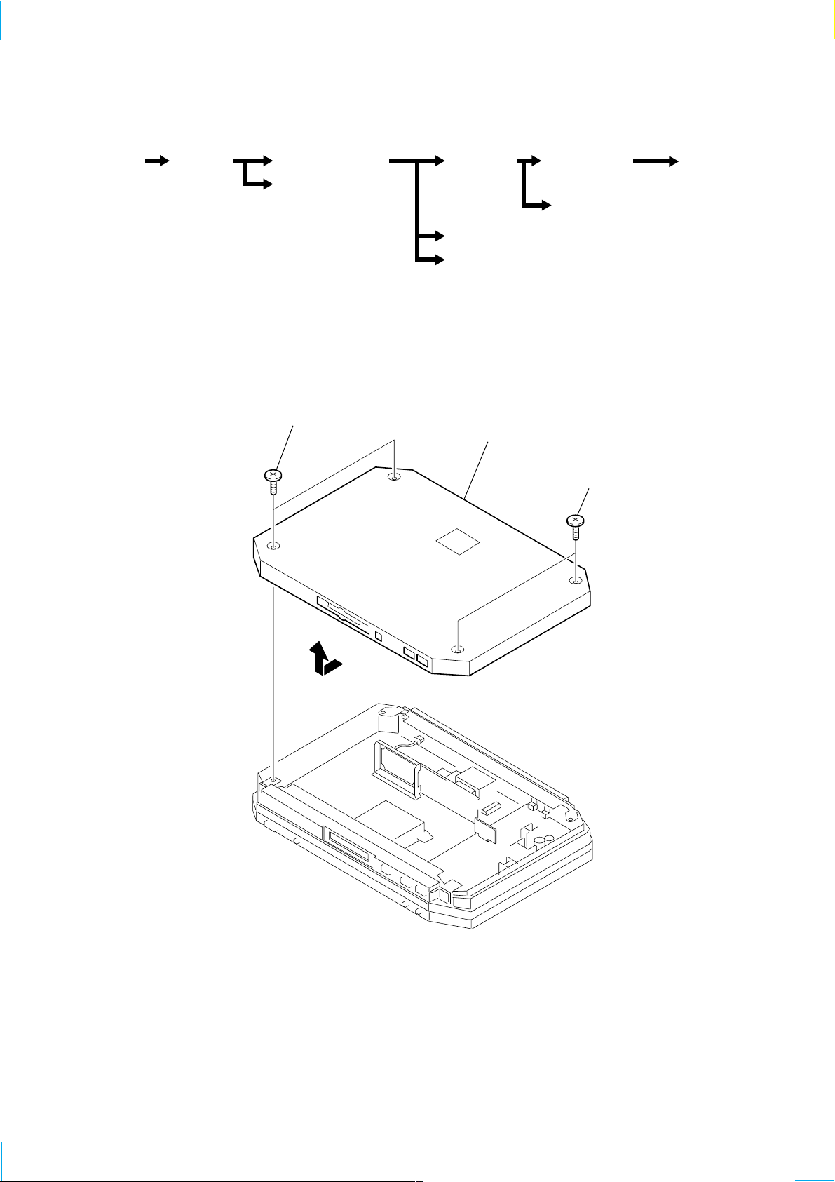
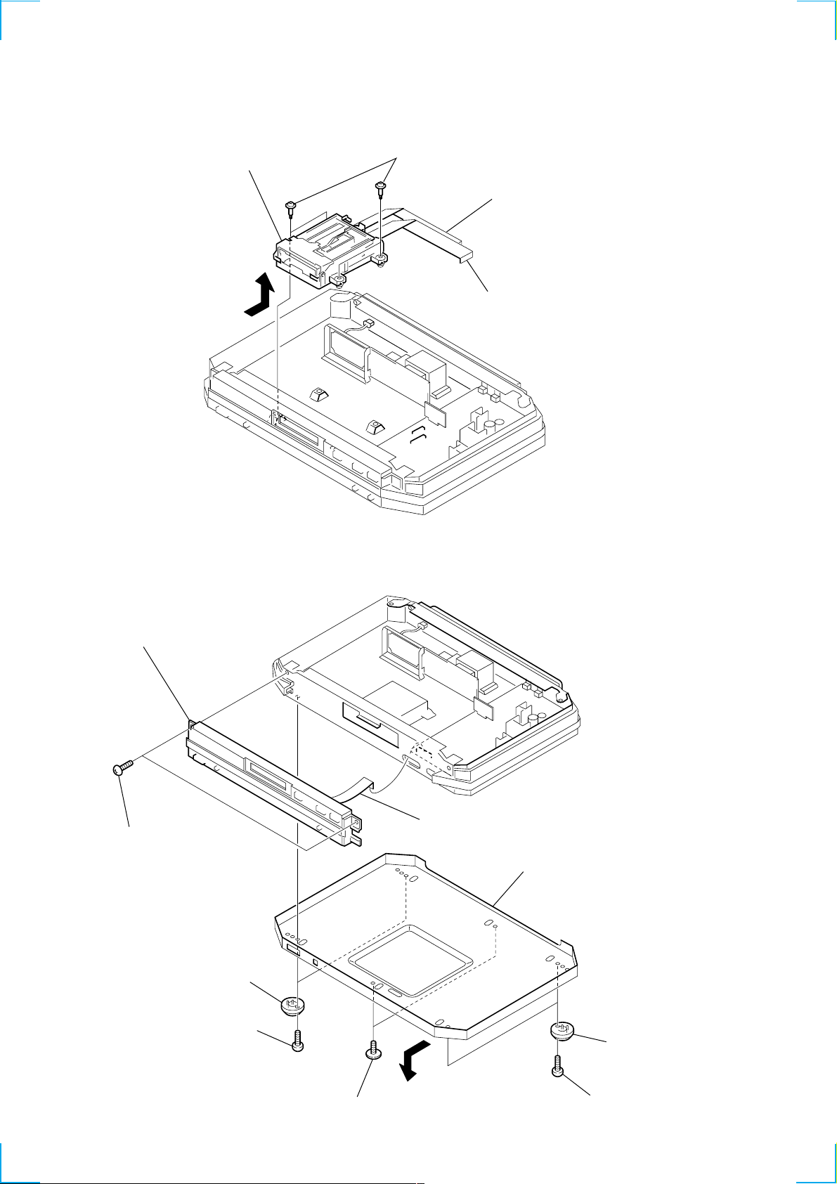
3-1. CASE (TOP)
1 two screws (case)
(Page 18)
(Page 18)
Holder Assy Over Write Head
(Page 20) (Page 20)
BD Board
(Page 21)
Clip Board and Main Board
Trans Board
(Page 19 )
2 case (top)
(Page 19)
1 two screws (case
Optical pick-up
Section (MD)
(Page 21)
3
17
3-2. MD MECHANISM DECK
)
5 MD mechanism deck
4
3 four screws
(BVTTWH M3), STEP
2 flat type wire (23 core)
(CN301)
1 flat type wire (27 core)
(CN302)
3-3. BASE (FRONT) ASSY, PANEL
8 base (front) assy, panel
7 two screws (BVTT 3x6)
6 flat type wire (17 core)
(CN306)
5 case (bottom)
18
2 two foot assy's
1 two screws (BVTT 3x8)
4
3 two screws (TP), flat head
2 two foot assy's
1 two screws (BVTT 3x8
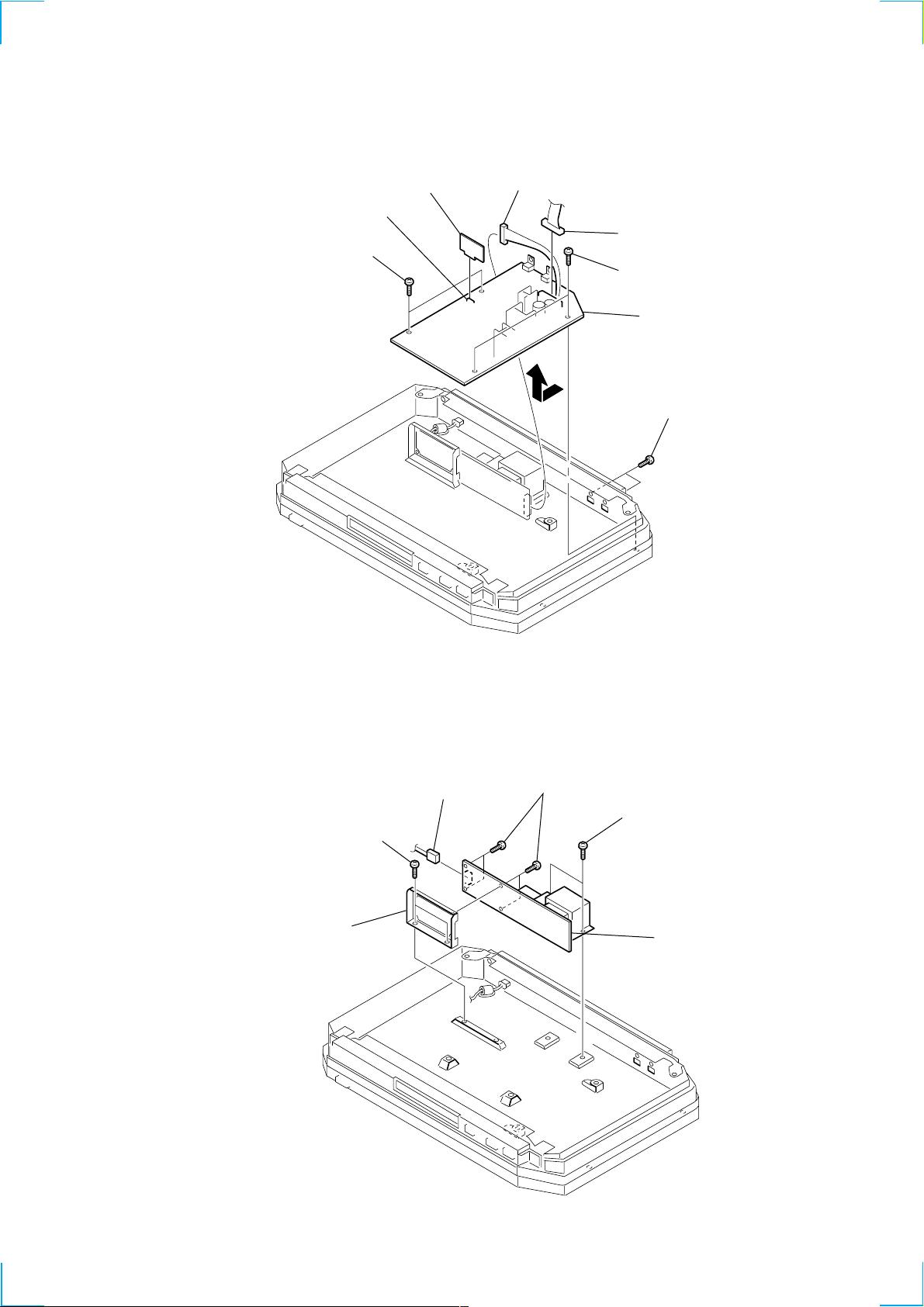
3-4. CLIP BOARD AND MAIN BOARD
)
d
2 CLIP board
1 connector (CN652)
6 two screws
(BVTT 3x6)
4 connector (CN902)
3 connector (CN903)
6 two screws (BVTT 3x6)
8 MAIN board
7
5 two screws (BVTT 2.6x6
3-5. TRANS BOARD
3 two screws
(BVTT 3x6)
5 bracket
(transformer)
1 connector
(CN901)
4 four screws
(BVTT 3x6)
2 two screws
(BVTT 3x6)
6 TRANS boar
19
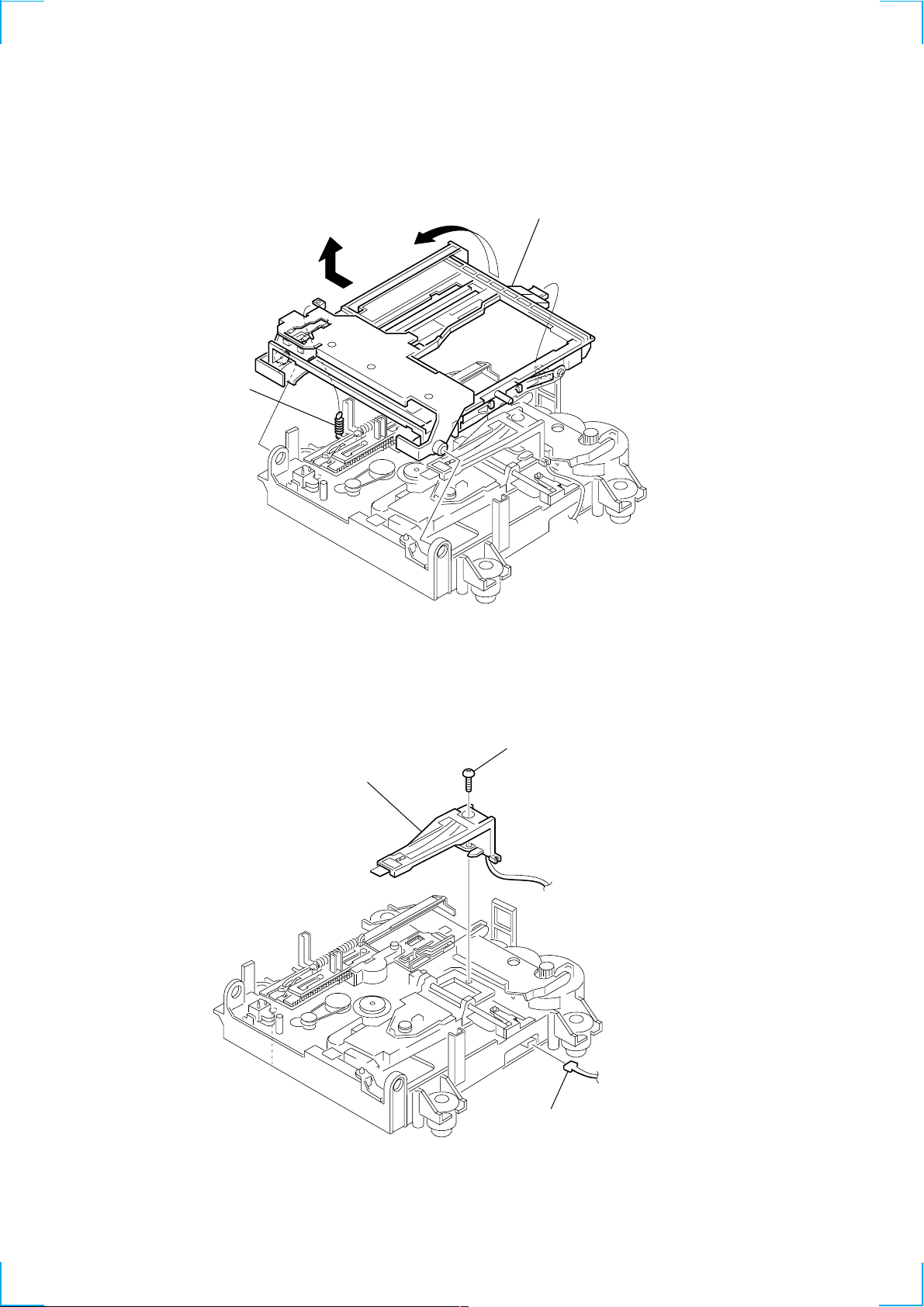
3-6. HOLDER ASSY
1 spring (holder),
tension
4
3
5 holder assy
2
3-7. OVER WRITE HEAD
2 screw (P 1.7x6)
3 over write head
(HR901)
1 connector (CN104)
20
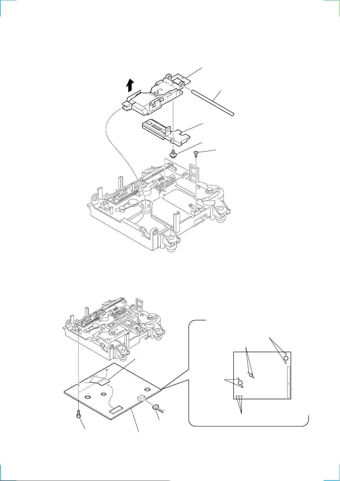
3-8. OPTICAL PICK-UP (MD)
)
(KMS-262A/J1N)
6 optical pick-up
4
5 shaft, main
2 base assy, SL
1 screw (P 1.7x6)
3 two screws (KTP 2x6
3-9. BD BOARD
3 two screws
(BTP 2 × 6)
5 connector
(CN101)
4 BD board
1 connector
(CN104)
2 Remove the solder
(Two portions)
2 Remove the solder
(Two portions)
2 Remove the solder
(Two portions)
M102
M101
M103
S102
2 Remove the solder
(Three portions)
21
SECTION 4
TEST MODE
4-1. PRECAUTIONS FOR USE OF TEST MODE
• As loading related operations will be performed regardless of the test mode operations being performed, be sure to check that the disc
is stopped before setting and removing it.
Even if the A button is pressed while the disc is rotating during continuous playback, continuous recording, etc., the disc will not stop
rotating.
Therefore, it will be ejected while rotating.
Be sure to press the A button after pressing the POWER“X2” button and the rotation of disc is stopped.
4-1-1. Recording laser emission mode and operating buttons
• Continuous recording mode (CREC 1MODE)
• Laser power check mode (LDPWR CHECK)
• Laser power adjustment mode (LDPWR ADJUS)
• Iop check (Iop Compare)
• Iop value nonvolatile writing (Iop NV Save)
• Traverse (MO) check (EF MO CHECK)
• Traverse (MO) adjustment (EF MO ADJUS)
• When pressing the z REC button.
4-2. SETTING THE TEST MODE
Procedure : While pressing the . button and x button, connect the power plug to an outlet, and release the . button and x
button.
When the test mode is set, “[Check]” will be displayed. Press the . or > button switches between the following three
groups; ··· y Check y Service y Develop y ···.
NOTE: Do not use the test mode in the [Develop] group.
If used, the unit may not operate normally.
If the [Develop] group is set accidentally, press the x button immediately to exit the [Develop] group.
4-3. EXITING THE TEST MODE
Press the POWER“X2” button. The disc is ejected when loaded, and “Standby” display blinks, and the STANDBY state is set.
4-4. BASIC OPERATIONS OF THE TEST MODE
All operations are performed using the . or > button, 7 button, and x button.
The functions of these buttons are as follows.
Function name
x button
7 button
. or > button
POWER button*
* NOTE: It dosen’t work in the ease of “X2” mode.
Cancel or move to top hierarchy
Set
Select
Set submenu
Function
22
4-5. SELECTING THE TEST MODE
There are 26 types of test modes as shown below. The groups can be switched by press the . or > button. After selecting the group
to be used, press the 7 button. After setting a certain group, press the . or > button switches between these modes.
Refer to “Group” in the table for details selected.
All adjustments and checks during servicing can be performed in the test mode in the Service group.
NOTE: Do not use the test mode in the [Develop] group.
If used, the unit may not operate normally.
If the [Develop] group is set accidentally, press the x button immediately to exit the [Develop] group.
Display
AUTO CHECK
Err Display
TEMP ADJUS
LDPWR ADJUS
Iop Write
Iop NV Save
EF MO ADJUS
EF CD ADJUS
FBIAS ADJUS
AG Set (MO)
AG Set (CD)
TEMP CHECK
LDPWR CHECK
EF MO CHECK
EF CD CHECK
FBIAS CHECK
ScurveCHECK
VERIFYMODE
DETRK CHECK
0920 CHECK
Iop Read
Iop Compare
ADJ CLEAR
INFORMATION
CPLAY2MODE
CREC 2MODE
Details
Automatic self-diagnosis
Error history display, clear
Temperature compensation offset adjustment
Laser power adjustment
Iop data writing
Writes current Iop value in read nonvolatile memory using microprocessor
Traverse (MO) adjustment
Traverse (CD) adjustment
Focus bias adjustment
Focus, tracking gain adjustment (MO)
Focus, tracking gain adjustment (CD)
Temperature compensation offset check
Laser power check
Traverse (MO) check
Traverse (CD) check
Focus bias check
S-curve check
Nonvolatile memory check
Detrack check
Most circumference check
Iop data display
Comparison with initial Iop value written in nonvolatile memory
Initialization of nonvolatile memory for adjustment values
Display of microprocessor version, etc.
Continuous playback mode (CLV2)
Continuous recording mode (CLV2)
Mark
Group
Check Service
• For details of each adjustment mode, refer to “5. Electrical Adjustments”.
For details of “Err Display”, refer to “Self-Diagnosis Function” on page 2.
• If a different mode has been selected by mistake, press the x button to exit that mode.
• Modes with (X) in the Mark column are not used for servicing and therefore are not described in detail. If these modes are set accidentally, press the x button to exit the mode immediately.
23
4-5-1. Operating the Continuous Playback Mode
1. Entering the continuous playback mode
1 Set the disc in the unit. (Whichever recordable discs or discs for playback only are available.)
2 Pressthe . or > button and display “CPLAY2MODE”.
3 Press the 7 button to change the display to “CPLAY2MID”.
4 When access completes, the display changes to “C = AD = ”.
Note : The numbers “ ” displayed show you error rates and ADER.
2. Changing the parts to be played back
1 Press the 7 button during continuous playback to change the display as below.
“CPLAY2MID” t “CPLAY2OUT” t “CPLAY2IN”
When pressed another time, the parts to be played back can be moved.
2 When access completes, the display changes to “C = AD = ”.
Note : The numbers “ ” displayed show you error rates and ADER.
3. Ending the continuous playback mode
1 Press the x button. The display will change to “CPLAY2MODE”.
2 Press the A button to remove the disc.
Note : The playback start addresses for IN, MID, and OUT are as follows.
IN 40h cluster
MID 300h cluster
OUT 700h cluster
4-5-2. Operating the Continuous Recording Mode (Use only when performing self-recording/palyback check.)
1. Entering the continuous recording mode
1 Set a recordable disc in the unit.
2 Press the . or > button and display “CREC 2MODE” .
3 Press the 7 button to change the display to “CREC 2MID”.
4 When access completes, the display changes to “CREC 2( )” and REC LED lights up.
Note : The numbers “ ” displayed shows you the recording position addresses.
2. Changing the parts to be recorded
1 When the 7 button is pressed during continuous recording, the display changes as below.
“CREC 2MID” t “CREC 2OUT” t “CREC 2IN”
When pressed another time, the parts to be recorded can be changed. REC LED goes off.
2 When access completes, the display changes to “CREC2 (
Note : The numbers “ ” displayed shows you the recording position addresses.
3. Ending the continuous recording mode
1 Press the x button. The display changes to “CREC 2MODE” and REC LED goes off.
2 Press the A button to remove the disc.
Note 1 : The recording start addresses for IN, MID, and OUT are as follows.
IN 40h cluster
MID 300h cluster
OUT 700h cluster
Note 2 : The x button can be used to stop recording anytime.
Note 3 : Do not perform continuous recording for long periods of time above 5 minutes.
Note 4 : During continuous recording, be careful not to apply vibration.
)” and REC LED lights up.
24
 Loading...