

Sony MDSJE-320 Service manual
MDS-JE320
SERVICE MANUAL
Ver. 1.1 2004. 12
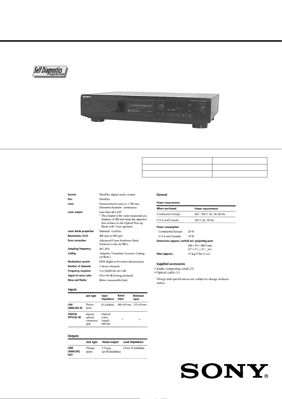
Model Name Using Similar Mechanism MDS-JE510
MD Mechanism Type MDM-3GC
Optical Pick-up Type KMS-260A/J1NP
SPECIFICATIONS
US Model
Canadian Model
AEP Model
9-922-894-12
2004L16-1
© 2004.12
MINIDISC DECK
Sony Corporation
Audio Group
Published by Sony Engineering Corporation
CAUTION
Danger of explosion if battery is incorrectly replaced.
Replace only with the same or equivalent type recommended by
the equipment manufacturer.
Discard used batteries according to manufacture’s instructions.
ADVARSEL!
Lithiumbatteri - Eksplosionsfare ved fejlagtig håndtering.
Udskiftning må kun ske med batteri af samme fabrikat og type.
Levér det brugte batteri tilbage til leverandøren.
ADVARSEL
Eksplosjonsfare ved feilakting skifte av batteri.
Benytt samme batteritype eller en tilsvarende type anbefalt av
apparatfabrikanten.
Brukte batterier katterier kasseres i henhold til fabrikantens
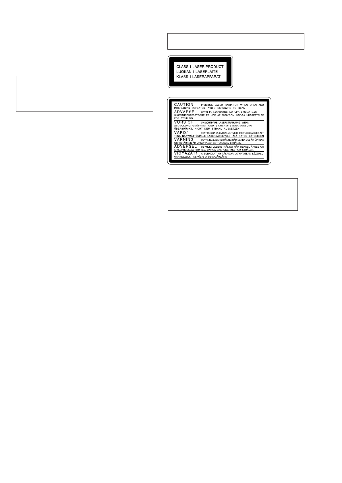
Laser component in this product is capable of emitting radiation
exceeding the limit for Class 1.
This appliance is classified as a
CLASS 1 LASER product.
The CLASS 1 LASER
PRODUCT MARKING is
located on the rear exterior.
VARNIG
Explosionsfara vid felaktigt batteribyte.
Använd samma batterityp eller en likvärdig typ som rekommenderas
av apparattillverkaren.
Kassera använt batteri enligt gällande föreakrifter.
VAROITUS
Parist voi räjähtää, jos se on virheellisesti asennettu.
V aihda paristo ainoastaan laite valmistajan suosittelemaan tyyppiin.
Hävitä käytetty paristo valmistajan ohjeiden mukaisesti.
This caution label is located inside the unit.
CAUTION
Use of controls or adjustments or performance of
procedures other than those specified herein may result in
hazardous radiation exposure.
Notes on chip component replacement
• Never reuse a disconnected chip component.
• Notice that the minus side of a tantalum capacitor may be
damaged by heat.
Flexible Circuit Board Repairing
• Keep the temperature of soldering iron around 270˚C
during repairing.
• Do not touch the soldering iron on the same conductor of the
circuit board (within 3 times).
• Be careful not to apply force on the conductor when soldering
or unsoldering.
SAFETY-RELATED COMPONENT WARNING !!
COMPONENTS IDENTIFIED BY MARK ! OR DOTTED LINE WITH
MARK ! ON THE SCHEMATIC DIAGRAMS AND IN THE PARTS
LIST ARE CRITICAL TO SAFE OPERATION. REPLACE THESE
COMPONENTS WITH SONY PARTS WHOSE PART NUMBERS
APPEAR AS SHOWN IN THIS MANUAL OR IN SUPPLEMENTS
PUBLISHED BY SONY.
— 2 —
ATTENTION AU COMPOSANT AYANT RAPPORT
À LA SÉCURITÉ!!
LES COMPOSANTS IDENTIFIÉS P AR UNE MARQUE ! SUR
LES DIAGRAMMES SCHÉMATIQUES ET LA LISTE DES
PIÈCES SONT CRITIQUES POUR LA SÉCURITÉ DE
FONCTIONNEMENT . NE REMPLA CER CES COMPOSANTS
QUE PAR DES PIÈCES SONY DONT LES NUMÉROS
SONT DONNÉS DANS CE MANUEL OU DANS LES
SUPPLÉMENTS PUBLIÉS PAR SONY.
SAFETY CHECK-OUT
TABLE OF CONTENTS
After correcting the original service problem, perform the following
safety checks before releasing the set to the customer:
Check the antenna terminals, metal trim, “metallized” knobs, screws,
and all other exposed metal parts for A C leakage. Check leakage as
described below.
LEAKAGE
The AC leakage from any exposed metal part to earth Ground and
from all exposed metal parts to any exposed metal part having a
return to chassis, must not exceed 0.5 mA (500 microampers).
Leakage current can be measured by any one of three methods.
1. A commercial leakage tester, such as the Simpson 229 or RCA
WT -540A. Follo w the manufacturers’ instructions to use these
instruments.
2. A battery-operated AC milliammeter. The Data Precision 245
digital multimeter is suitable for this job.
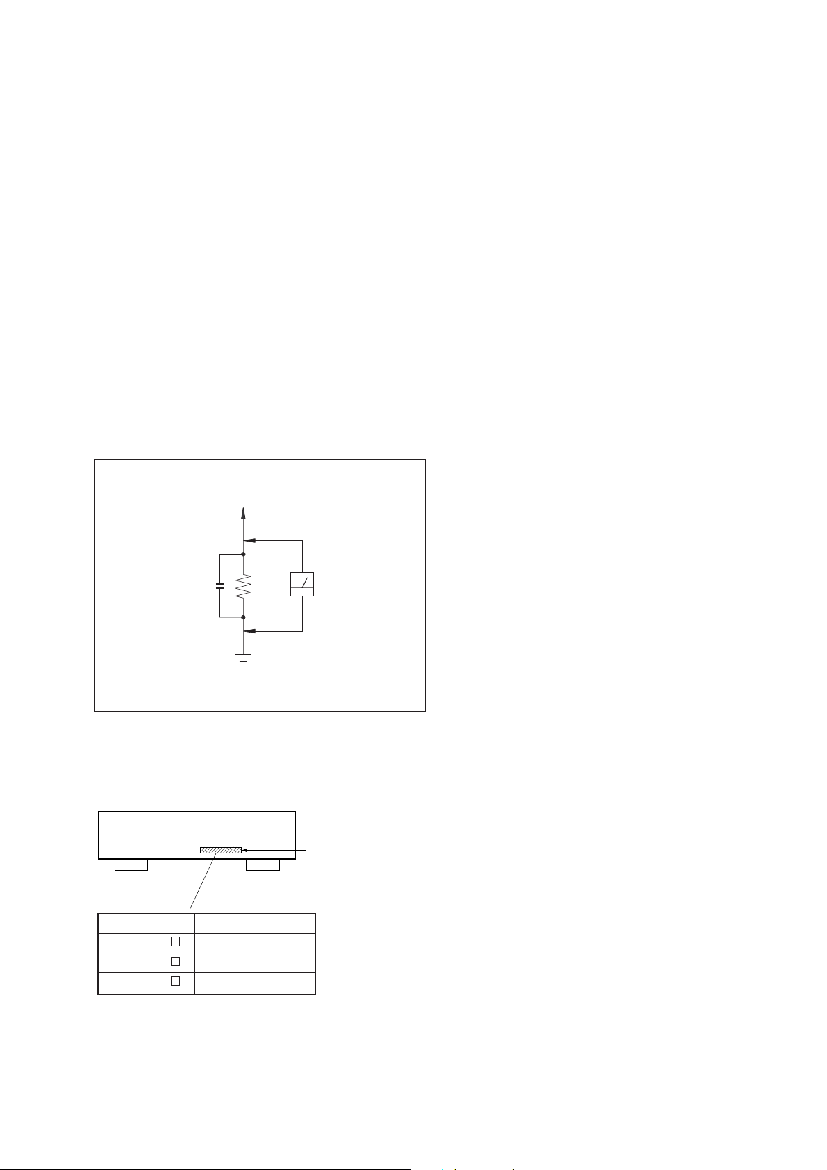
3. Measuring the voltage drop across a resistor by means of a
VOM or battery-operated A C voltmeter . The “limit” indication
is 0.75 V, so analog meters must have an accurate lo w-v olta ge
scale. The Simpson 250 and Sanwa SH-63Trd are e xamples of
a passive VOM that is suitable. Nearly all battery operated
digital multimeters that have a 2V AC range are suitable. (See
Fig. A)
T o Exposed Metal
Parts on Set
AC
0.15
µ
F
Fig. A. Using an A C v oltmeter to check A C leakage.
1.5 k
Ω
Earth Ground
Voltmeter
(0.75 V)
1. SERVICING NOTE .......................................................... 5
2. GENERAL ..........................................................................8
3. DISASSEMBLY
3-1. Case and Front Panel Assembly ...................................... 9
3-2. Bracket (T), (L) and (R)..................................................9
3-3. BD Board ...................................................................... 10
3-4. SUB Chassis ................................................................. 10
3-5. Shutter Assembly .......................................................... 11
3-6. Over Write Head ........................................................... 11
3-7. Slider Complete Assembly............................................ 12
4. TEST MODE ..................................................................... 13
5. ELECTRICAL ADJUSTMENTS ...............................16
6. DIAGRAMS
6-1. Brock Diagrams
• BD Section .......................................................................21
• Main Section .................................................................... 23
6-2. Circuit Boards Location................................................25
6-3. Printed Wiring Board — BD Section — ......................27
6-4. Schematic Diagram — BD Section (1/2) — ................ 29
6-5. Schematic Diagram — BD Section (2/2) — ................ 31
6-6. Printed Wiring Board — Main Section —.................... 33
6-7. Schematic Diagram — Main Section (1/3) —.............. 35
6-8. Schematic Diagram — Main Section (2/3) —.............. 37
6-9. Schematic Diagram — Main Section (3/3) —.............. 39
6-10. Printed Wiring Board — Display Section — .............. 41
6-11. Schematic Diagram — Display Section — ................43
6-12. Printed Wiring Board — Switch Section — ...............45
6-13. Schematic Diagram — Switch Section —.................. 47
6-14. IC Brock Diagrams — BD Section—......................... 49
6-15. IC Pin Functions .........................................................54
7. EXPLODED VIEWS
7-1. Main Section ................................................................. 63
7-2. Front Panel Section ....................................................... 64
7-3. Mechanism Deck Section (1) (MDM-3GC) ................. 65
7-4. Mechanism Deck Section (2) (MDM-3GC) ................. 66
MODEL IDENTIFICATION
— BACK PANEL —
Parts No.
4-990-651-1
4-990-651-4
4-990-651-5
US model
Canadian model
AEP model
8. ELECTRICAL PARTS LIST ........................................ 67
Parts No.
Model
— 3 —

[SELF-DIAGNOSIS FUNCTION]
C11
Protected
Self-diagnosis display
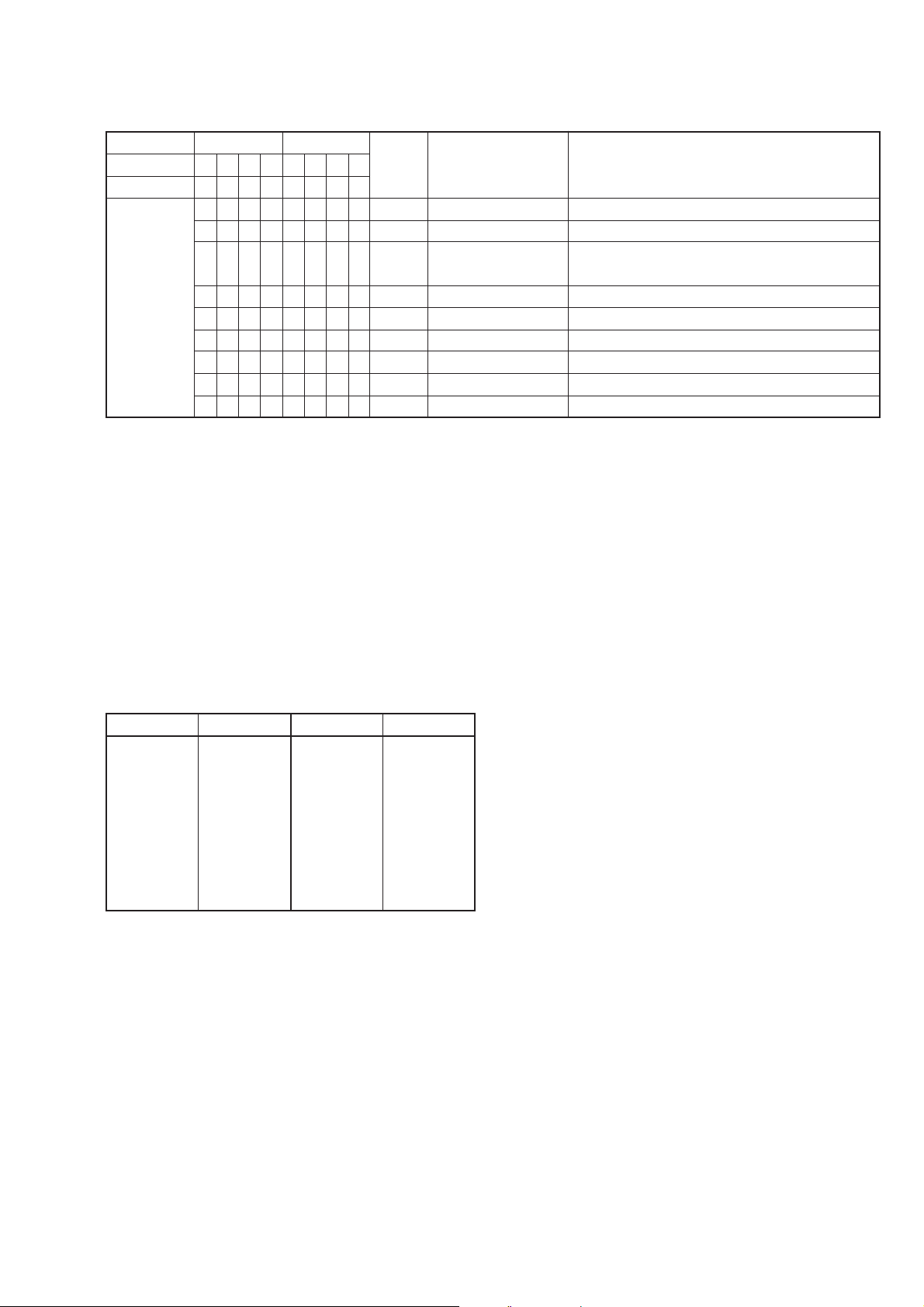
The self-diagnosis function consists of error codes for users which are displayed automatically when errors occur, and error codes which show the error
history in the test mode during servicing.For detail on how to view error codes for users, refer to the following box in the instruction manual.
Self-Diagnosis Function
The deck has a self-diagnosis display. This function shows a three-digit display (a combination of a letter and figures)
and the corresponding message alternately, so you can check the deck’s condition. If such a display appears, check the
following table in order to resolve the problem. Should any problem persist, consult your nearest Sony dealer.
Three-digit display/Message Cause/Remedy
C11/Protected The inserted MD is record-protected.
C13/REC Error The recording was not made properly.
C13/Disc Error The deck could not read the TOC of the MD properly.
C14/Disc Error The deck could not read the TOC of the MD properly.
C71/Din Unlock A moment’s lighting is due to the signals of the digital program being recorded.
/Take out the MD, and close the record-protect tab (page 9.)
/Set the deck in a stable place, and repeat the recording procedure.
The inserted MD is dirty (with smudges, fingerprints, etc.) scratched, or not up to standards.
/Replace the disc, and repeat the recording procedure.
/Take out the MD, and insert it again.
/Insert another disc.
/If possible, erase all tracks on the MD using the All Erase Function on page 28.
This does not affect the recorded material.
While recording from a digital component connected through the digital input connector,
the digital connecting cable was unplugged or the digital component turned off.
/Connect the cable or turn the digital component back on.
— 4 —
SECTION 1
SERVICING NOTE
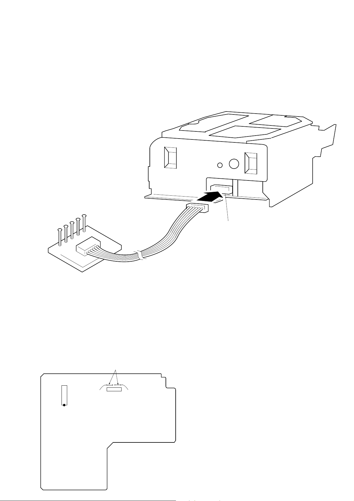
JIG FOR CHECKING BD BOARD WAVEFORM
The special jig (J-2501-124-A) is useful for checking the waveform of the BD board. The names of terminals and the checking items to be
performed are shown as follows.
I+3V : For measuring IOP (Check the deterioration of the optical pick-up laser)
IOP : For measuring IOP (Check the deterioration of the optical pick-up laser)
TEO : TRK error signal (Traverse adjustment)
VC : Reference level for checking the signal
RF : RF signal (Check jitter)
RF
VC
TEO
IOP
I + 3V
Jig
(J-2501-124-A)
CN110
FORCED RESET
The system microprocessor can be reset in the following way.
Use these methods when the unit cannot be operated normally due to the overrunning of the microprocessor, etc.
Method :
Disconnect the power plug, short-circuit jumper wire of JW70 and JW181.
[MAIN BOARD] (Component Side)
Jumper wire
Mechanism deck
IC301
BT301
JW181JW70
— 5 —

RETRY CAUSE DISPLAY MODE
• In this test mode, the causes for retry of the unit during recording can be displayed on the fluorescent display tube.
This is useful for locating the faulty part of the unit.
• The data amount stored in DRAM, number of retries, and retry cause are displayed. Each is displayed in hexadecimal number.
• The display of the DRAM data amount enables data reading, accumulation, ejection, and writing to be performed smoothly. If writing is
not smooth, data may decrease considerably.
Method:
1. Load a recordable disc whose contents can be erased into the unit.
2. Press the EDIT/NO button several times to display “All Erase?” on the fluorescent display tube.
3. Press the YES button.
4. When “All Erase??” is displayed on the fluorescent display tube, the numbers on the music calendar will start blinking.
5. Press the YES button to display “Complete”, and press the p button immediately and continue pressing for about 10 seconds.
6. When the “TOC” displayed on the fluorescent display tube goes off, release the p button.
7. Press the r REC and · PLAY buttons to start recording.
8. Press the DISPLAY/CHAR button to display the test mode (Fig. 1), and check the display.
9. The Rt value increases with each retry . If an error occurs after a retry, “Retry Error” will be displayed, and the number of retries counted
will be set back to 0.
10. T o exit the test mode, press the 1/u b utton. T urn OFF the po wer , and after “TOC” disappears, disconnect the po wer plug from the outlet.
Fig. 1 Reading the Test Mode Display
Fluorescent Display Tube Signs
SC @@ Rt # # ∗ ∗
@@ : Displays the DRAM memory amount when at all times.
# # : Displays the number of retries. When a retry error occurs, the number will be set back to 0.
* * : Cause of retry
All three displays above are in hexadecimal numbers.
— 6 —
Reading the Retry Cause Display
Higher Bits Lower Bits
Hexadecimal
Bit
Binary
Reading the Display:
Convert the hexadecimal display into binary display. If more than two causes, they will be added.
Example
When 42 is displayed:
Higher bit : 4 = 0100 n b6
Lower bit : 2 = 0010 n b1
In this case, the retry cause is combined of “CLV unlock” and “ader5”.
84218421
b7 b6 b5 b4 b3 b2 b1 b0
00000000
00000001
00000010
00000100
00001000
00010000
00100000
01000000
10000000
Hexa-
decimal
00
01
02
04
08
10
20
40
80
Cause of Retry Occurring conditions
Spindle is slow
(Not used)
ader5
Discontinuous address
(Not used)
FCS incorrect
IVR rec error
CLV unlock
Access fault
When spindle rotation is detected as slow
(Not used)
When ADER was counted more than
five times continuously
When ADIP address is not continuous
(Not used)
When not in focus
When ABCD signal level exceeds the specified range
When CLV is unlocked
When access operation is not performed normally
When A2 is displayed:
Higher bit : A = 1010 n b7+b5
Lower bit : 2 = 0010 n b1
The retry cause in this case is combined of “access fault”, “IVR rec error”, and “ader5”.
Hexadecimal n Binary Conversion Table
Hexadecimal Binary Hexadecimal Binary
0
1
2
3
4
5
6
7
0000
0001
0010
0011
0100
0101
0110
0111
8
9
A
B
C
D
E
F
1000
1001
1010
1011
1100
1101
1110
1111
— 7 —
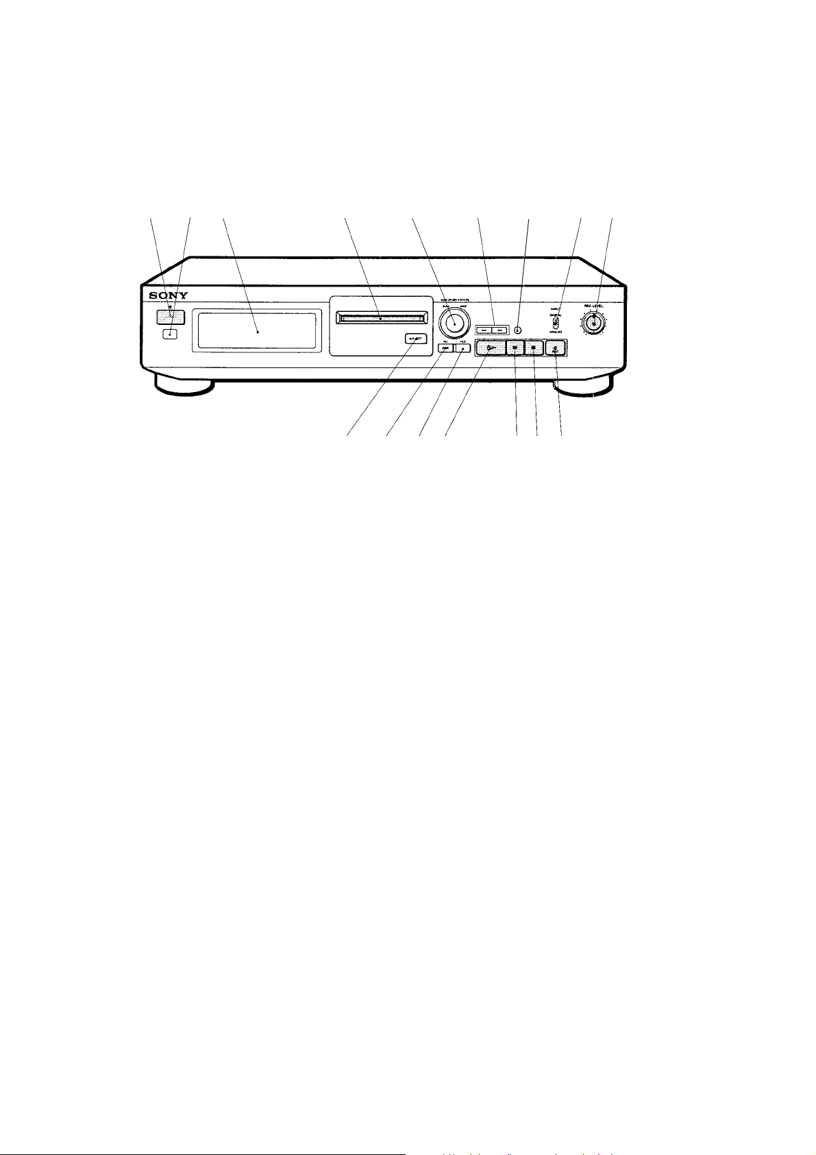
Location of Parts and Controls
23
1
SECTION 2
GENERAL
456 8
7
9
1 1/u (Power) switch
2 Remote sensor
3 Display window
4 Disc compartment
5 AMS knob
6 0/) buttons
7 DISPLAY/CHAR button
8 INPUT switch
!ª
!• !¶ !§
9 REC LEVEL knob
!£ r REC (recording) button
!¢ p (stop) button
!∞ P (pause) button
!§ · (play) button
!¶ YES button
!• EDIT/NO button
!ª § EJECT button
!∞ !¢ !£
— 8 —
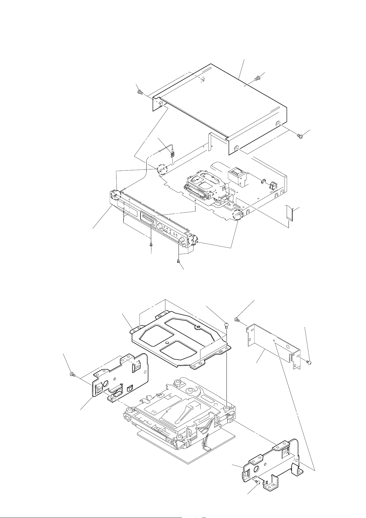
SECTION 3
4
Case
3
Screw
(case 3 TP 2)
2
T wo screws
(Case 3 TP 2)
6
Flat type wire
(CN303)
claw
8
Four screws
(BVTP3
×
8)
9
Remove the front panel assembly
releasing two claws.
claw
1
T wo screws
(Case 3 TP 2)
7
Three screws
(BVTP3
×
8)
5
Ground terminal
DISASSEMBLY
Note : Follow the disassembly procedure in the numerical order given.
3-1. CASE AND FRONT PANEL ASSEMBLY
3-2. BRACKET (T), (L) AND (R)
6
T wo screws
(BVTT2
×
3)
7
Bracket (L)
2
Bracket (T)
1
Four screws
(BVTT2
×
3)
5
Bracket (joint)
9
Bracket (R)
4
Screw (BVTT2×3)
3
Screw (BVTT2×3)
8
— 9 —
T wo screws
(BVTT2
×
3)
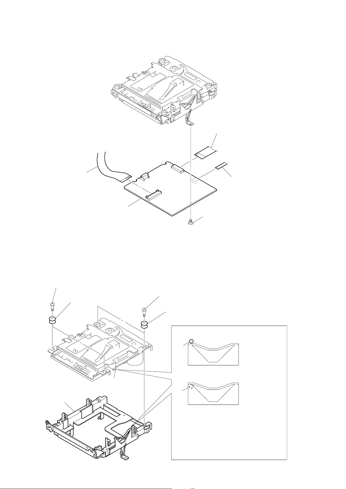
3-3. BD BOARD
)
4
OP relay flexible board
5
BD board
2
Flat type wire (15 core)
1
(Over write head
3
Screw (BVTT2×4)
Flexible board
3-4. SUB CHASSIS
1
Two step screws
5
Sub chassis
3
T wo insulators
Part A
2
Two step screws
4
T wo insulators
Part A
Part A
NG
OK
— 10 —
Take care so that the part A
may be right position when installing.
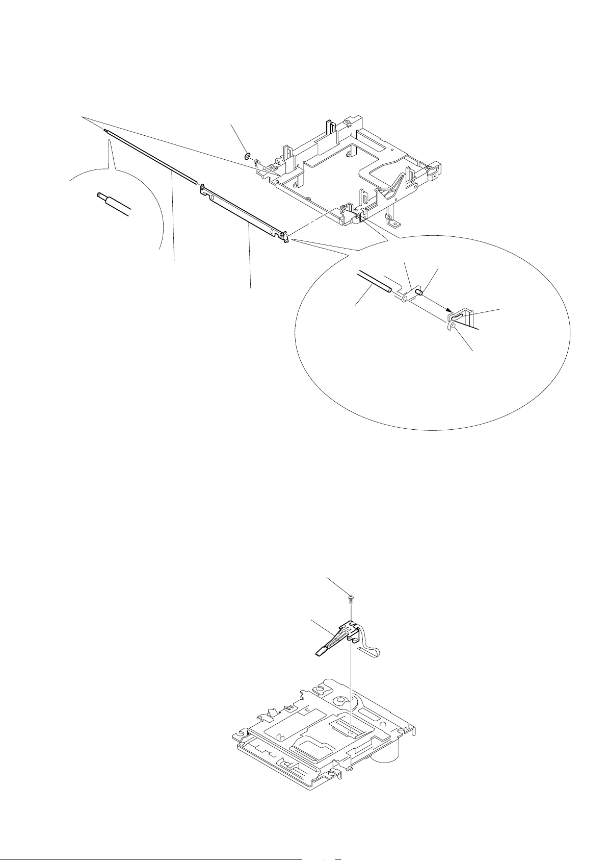
3-5. SHUTTER ASSEMBLY
1
Stepper washer
2
Shaft (shutter)
3-6. OVER WRITE HEAD
3
Shutter assembly
Shutter assembly
Shaft (shutter)
Shaft (lid)
Hole B
Hole A
When installing, install the shaft
(shutter) into the hole A as shown
in the figure before installing the
shaft (lid) into the hole B.
1
Precision screw (P1.7×6)
2
Over write head
— 11 —
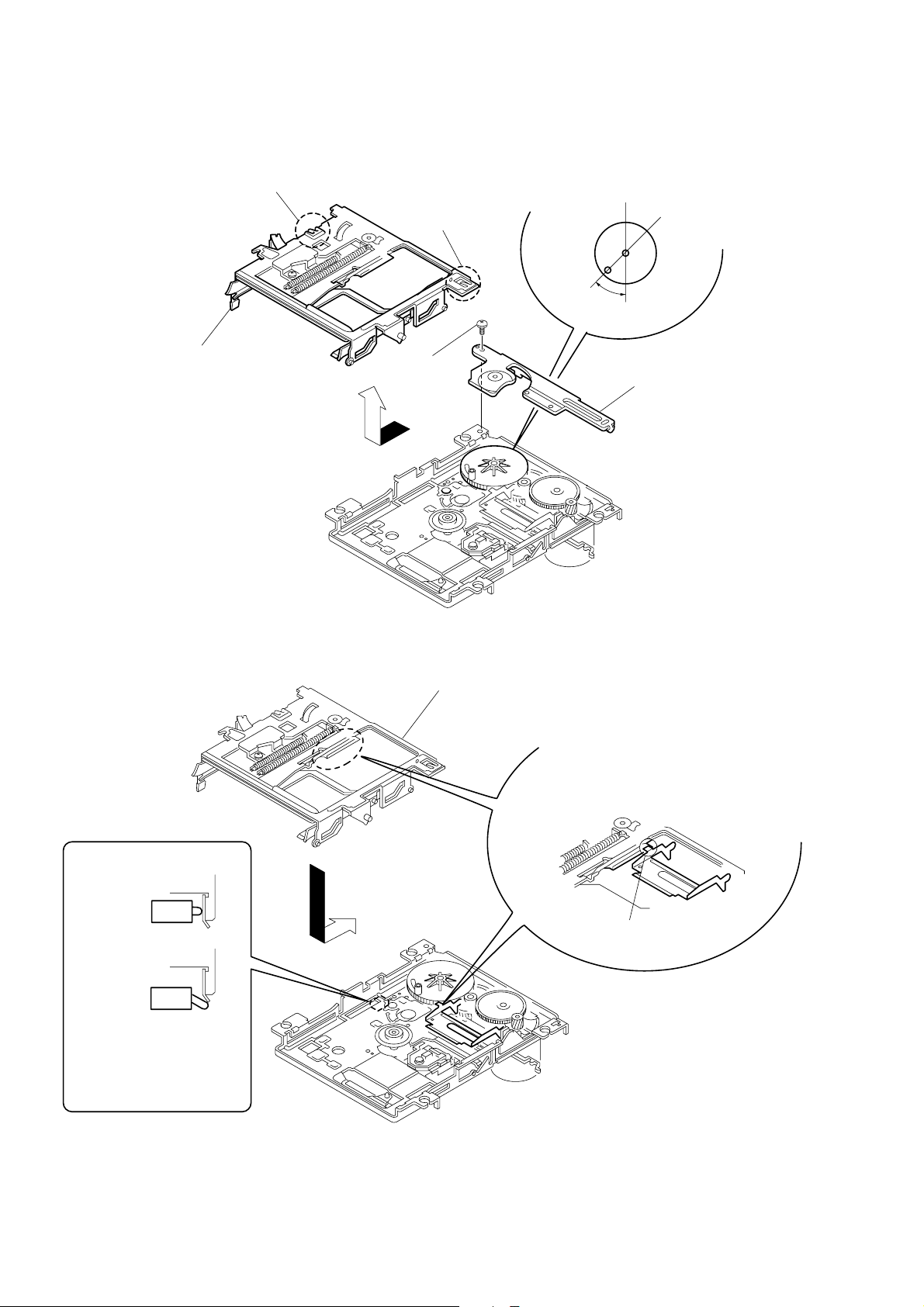
3-7. SLIDER COMPLETE ASSEMBLY
claw
4
Remove the slider complete assembly
in the direction of arrow with putting
out of two claws.
claw
1
Screw
(M1.7
3
Set the shaft of Gear (LA) to be at the
position in the figure.
45
°
×
2)
2
Retainer (gear)
• Note for Installation of Slider Complete Assembly
OK
NG
Take care not to damage
the detective switch.
Slider assembly
Install the part A of lever (head up)
to pass over the slider complete assembly.
Part A
— 12 —

SECTION 4
TEST MODE
4-1. PRECAUTIONS FOR USE OF TEST MODE
1 As loading related operations will be performed regardless of the test mode operations being performed, be sure to check that the disc is
stopped before setting and removing it.
Even if the §EJECT button is pressed while the disc is rotating during continuous playback, continuous recording, etc., the disc will not
stop rotating.
Therefore, it will be ejected while rotating.
Be sure to press the §EJECT button after pressing the EDIT/NO button and the rotation of disc is stopped.
2 The erasing-protection tab is not detected in the test mode. Therefore, operating in the recording laser emission mode and pressing the
rREC button, the recorded contents will be erased regardless of the position of the tab . When using a disc that is not to be er ased in the
test mode, be careful not to enter the continuous recording mode and traverse adjustment mode.
4-1-1. Recording laser emission mode and operating buttons
1. Continuous recording mode (CREC MODE)
2. Traverse adjustment mode (EFBAL ADJUST)
3. Laser power adjustment mode (LDPWR ADJUST)
4. Laser power check mode (LDPWR CHECK)
5. When pressing the rREC button.
4-2. SETTING THE TEST MODE
While pressing the AMS knob, insert the power plug into the power supply outlet, and release the AMS knob.
4-3. EXITING THE TEST MODE
When the 1/u button is pressed, it becomes in the STANDBY mode. Or unplug the power plug from an outlet.
4-4. BASIC OPERATIONS OF THE TEST MODE
All operations are performed using the AMS knob, YES button, and EDIT/NO button.
The functions of these buttons are as follows.
Function name
AMS knob
YES button
EDIT/NO button
Changes parameters and modes
Proceeds onto the next step. Finalizes input.
Returns to previous step. Stops operations.
Function
4-5. SELECTING THE TEST MODE
Thirteen test modes are selected by turning the AMS knob.
Display
TEMP ADJUST
LDPWR ADJUST
LDPWR CHECK
EFBAL ADJUST
FBIAS ADJUST
FBIAS CHECK
CPLAY MODE
CREC MODE
DETRK CHECK
S curve CHECK
EEP MODE
MANUAL CMD
SVDATA READ
Temperature compensation offset adjustment
Laser power adjustment
Laser power check
Traverse adjustment
Focus bias adjustment
Focus bias check
Continuous playback mode
Continuous recording mode
Detrack check
S curve check ∗
Non-volatile memory mode ∗
Manual command transfer mode ∗
Data reading out mode ∗
Contents
For detailed description of each adjustment mode, refer to “5. Electrical Adjustments”.
If a different adjustment mode has been selected by mistake, press the EDIT/NO button to exit from this mode.
* The EEP MODE, S curve CHECK, MANU AL CMD and SVD AT A READ are not used in servicing. If set accidentally , press the EDIT/NO
button immediately to exit this mode.
— 13 —

4-5-1. Operating the Continuous Playback Mode
1. Entering the continuous playback mode
1 Set the disc in the unit. (Whichever recordable discs or discs for playback only are available.)
2 Rotate the AMS knob and display “CPLAY MODE”.
3 Press the YES button to change the display to “CPLAY MID”.
4 When access completes, the display changes to “C1 = AD = ”.
Note : The numbers “ ” displayed show you error rates and ADER.
2. Changing the parts to be played back
1 Press the YES button during continuous playback to change the display as below.
“CPLAY MID” n “CPLAY OUT”n “CPLAY IN”
4
When pressed another time, the parts to be played back can be moved.
2 When access completes, the display changes to “C1 = AD = ”.
Note : The numbers “ ” displayed show you error rates and ADER.
3. Ending the continuous playback mode
1 Press the EDIT/NO button. The display will change to “CPLAY MODE”.
2 Press the §EJECT button to remove the disc.
Note : The playback start addresses for IN, MID, and OUT are as follows. In case you w ant to display the address of the playback position
on the display, press the DISPLAY/CHAR button and display “CPLAY ( )”.
IN 40h cluster
MID 300h cluster
OUT 700h cluster
4-5-2. Operating the Continuous Recording Mode
1. Entering the continuous recording mode
1 Set a recordable disc in the unit. (Refer to Note 3)
2 Rotate the AMS knob and display “CREC MODE”.
3 Press the YES button to change the display to “CREC MID”.
4 When access completes, the display changes to “CREC ( )” and REC lights up.
Note : The numbers “ ” displayed shows you the recording position addresses.
2. Changing the parts to be recorded
1 When the YES button is pressed during continuous recording, the display changes as below.
“CPLAY MID” n “CPLAY OUT”n “CPLAY IN”
4
When pressed another time, the parts to be recorded can be changed. REC goes off.
2 When access completes, the display changes to “CREC (
)” and REC lights up.
Note : The numbers “ ” displayed shows you the recording position addresses.
3. Ending the continuous recording mode
1 Press the EDIT/NO button. The display changes to “CREC MODE” and REC goes off.
2 Press the §EJECT button to remove the disc.
Note 1 : The recording start addresses for IN, MID, and OUT are as follows.
IN 40h cluster
MID 300h cluster
OUT 700h cluster
Note 2 :The EDIT/NO button can be used to stop recording anytime.
Note 3 :During the test mode, the erasing-protection tab will not be detected. Therefore be careful not to set the continuous recording
mode when a disc not to be erased is set in the unit.
Note 4 :Do not perform continuous recording for long periods of time above 5 minutes.
Note 5 :During continuous recording, be careful not to apply vibration.
4-5-3. Non-Volatile Memory Mode
This mode reads and writes the contents of the non-volatile memory.
It is not used in servicing. If set accidentally, press the EDIT/NO button immediately to exit it.
— 14 —
4-6. FUNCTIONS OF OTHER BUTTONS
Function
·
p
)
0
r REC
DISPLAY/
CHAR
Sets continuous playback when pressed in the STOP state. When pressed during continuous playback, the tracking servo turns ON/OFF.
Stops continuous playback and continuous recording.
The sled moves to the outer circumference only when this is pressed.
The sled moves to the inner circumference only when this is pressed.
Turns recording ON/OFF when pressed during continuous playback.
Switches the display when pressed.Returns to previous step. Stops operations.
Contents
Note : The erasing-protection tab is not detected during the test mode. Recording will start regardless of the position of the erasing-protection
tab when the r REC button is pressed.
4-7. TEST MODE DISPLAYS
Each time the DISPLAY/CHAR button is pressed, the display changes in the following order.
MODE displaynError rate displaynAddress displaynAuto gain displaynIVR display
The auto gain display and the IVR display are not used for servicing.
1. MODE display
Displays “TEMP ADJUST”, “CPLAY MODE”, etc.
2. Error rate display
Error rates are displayed as follows.
C1 =
C1 = : Indicates C1 error
AD= : Indicates ADER
3. Address display
Addresses are displayed as follows. (MO : Recordable disc, CD : Disc for playback only)
h= s = (MO pit and CD)
h= a = (MO groove)
h= : Header address
s = : SUBQ address
a = : ADIP address
* “_” is displayed when the address cannot be read.
4. Auto gain display
Auto gains are displayed as follows.
AG F = T =
F= Focus auto gain collection value.
T= Tracking auto gain collection value.
AD =
4-8. MEANINGS OF OTHER DISPLAYS
Display
”
P
REC
CLOCK
TRACK
DISC
DA TE
A. SPACE
A – B
During continuous playback
Tracking servo OFF
Recording mode ON
CLV LOCK
Pit
High reflection
CLV-S
ABCD adjustment completed
Focus auto gain successful
Tracking auto gain successful
Light Off Blinking
Contents
STOP
Tracking servo ON
Recording mode OFF
CLV UNLOCK
Groove
Low reflection
CLV-A
Focus auto gain successful
Tracking auto gain failed
— 15 —
SECTION 5
ELECTRICAL ADJUSTMENTS
5-1. PRECAUTIONS FOR CHECKING LASER
DIODE EMISSINON
T o check the emission of the laser diode dur ing adjustments, never
view directly from the top as this may lose your eye-sight.
5-2. PRECAUTIONS FOR USE OF OPTICAL PICK-
UP (KMS-260A)
As the laser diode in the optical pick-up is easily damaged by static
electricity, solder the laser tap of the flexible board when using it.
Before disconnecting the connector, desolder f irst. Before connecting
the connector, be careful not to remov e the solder. Also take adequate
measures to prevent damage by static electricity . Handle the flexible
board with care as it breaks easily.
pick-up
laser tap
Optical pick-up flexible board
flexible board
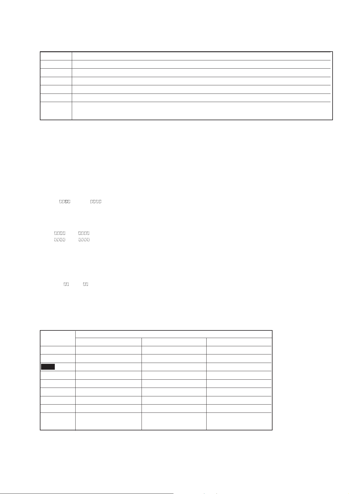
1.Temperature
compensation
offset adjustment
2. Laser power
adjustment
3. Traverse
adjustment
4. Focus bias
adjustment
5. Error rate check
Optical
Pick-up
G
¬
¬
¬
¬
¬
¬
¬
¬
¬
BD Board
IC101, IC121, IC192D101IC171
¬
G
G
G
G
¬
¬
¬
¬
¬
5-3. PRECAUTIONS FOR ADJUSTMENTS
1) When replacing the following parts, perform the adjustments
and checks with ¬ in the order shown in the following table.
2) Set the test mode when performing adjustments.
After completing the adjustments, exit the test mode.
3) Perform the adjustments in the order shown.
4) Use the following tools and measuring devices.
• Check Disc (MD) TDYS-1
(Parts No. 4-963-646-01)
• Laser power meter LPM-8001 (Parts No. J-2501-046-A)
• Oscilloscope (Measure after performing CAL of prove.)
• Digital voltmeter
• Thermometer
• Jig for checking BD board waveform
(Parts No. : J-2501-124-A)
5) When observing several signals on the oscilloscope, etc.,
make sure that VC and ground do not connect inside the
oscilloscope.
(VC and ground will become short-circuited.)
6) Using the above jig enables the wav eform to be checked without
the need to solder.
(Refer to Servicing Note on page 4.)
Note :When performing laser power checks and adjustment
5-4. CREATING CONTINUOUSLY RECORDED DISC
• This disc is used in focus bias adjustment and error rate check.
1. Insert a disc (blank disc) commercially available.
2. Rotate the AMS knob and display “CREC MODE”.
3. Press the YES button again to display “CREC MID”.
4. Complete recording within 5 minutes.
5. Press the EDIT/NO button and stop recording .
6. Press the §EJECT button and remove the disc.
The above has been how to create a continuous recorded data for the
focus bias adjustment and error rate check.
Note :
• Be careful not to apply vibration during continuous recording.
— 16 —
(electrical adjustment), use of the new MD laser power meter
8010S (J-2501-145-A) instead of the conventional laser po wer
meter is convenient.
It sharply reduces the time and trouble to set the laser power
meter sensor onto the objective lens of the pick-up.
The following describes how to create a continuous recording disc.
Display “CREC (0300)” and start to recording.
5-5. TEMPERATURE COMPENSATION OFFSET
ADJUTMENT
Save the temperature data at that time in the non-volatile memory
as 25 ˚C reference data.
Note :
1. Usually, do not perform this adjustment.
2. Perform this adjustment in an ambient temperature of 22 ˚C
to 28 ˚C. Perform it immediately after the power is turned on
when the internal temperature of the unit is the same as the
ambient temperature of 22 ˚C to 28 ˚C.
3. When D101 has been replaced, perform this adjustment after
the temperature of this part has become the ambient
temperature.
Adjusting Method :
1. Rotate the AMS knob and display “TEMP ADJUST”.
2. Press the YES button and select the “TEMP ADJUST” mode.
3. “TEMP = ” and the current temperature data will be
displayed.
4. To save the data, press the YES button.
When not saving the data, press the EDIT/NO button.
5. When the YES button is pressed, “TEMP = SAVE” will be
displayed and turned back to “TEMP ADJUST” display then.
When the EDIT/NO button is pressed, “TEMP ADJUST” will
be displayed immediatelly.
Specified Value :
The “TEMP = ” should be within “E0 - EF”, “F0 - FF”, “00 0F”, “10 - 1F” and “20 - 2F”.
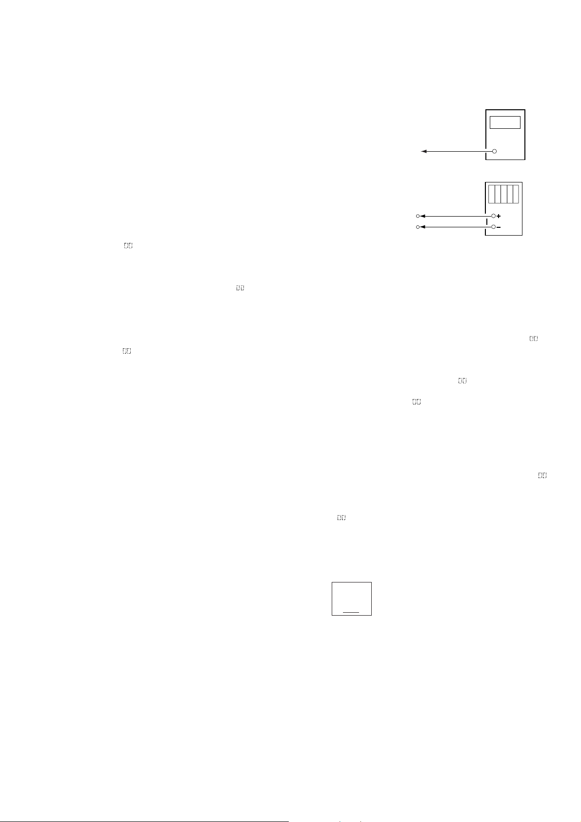
5-6. LASER POWER ADJUSTMENT
Connection :
Laser power
meter
Optical pick-up
objective lens
Digital volt meter
BD board
CN110 pin 5 (I+3V)
CN110 pin 4 (IOP)
Adjusting Method :
1. Set the laser power meter on the objective lens of the optical
pick-up. (When it cannot be set properly, pr ess the 0 button
or ) button to move the optical pick-up.)
Connect the digital volt meter to CN110 pin 5 (I+3V) and
CN110 pin 4 (IOP).
2. Rotate the AMS knob and display “LDPWR ADJUST”.
(Laser power : For adjustment)
3. Press the YES button once and display “LD 0.9 mW $ ”.
4. Rotate the AMS knob so that the reading of the laser power
meter becomes 0.86 to 0.92 mW. Press the YES button after
setting the range knob of the laser power meter, and save the
adjustment results. (“LD SAVE $ ” will be displayed for a
moment.)
5. Then “LD 7.0 mW $ ” will be displayed.
6. Rotate the AMS knob so that the reading of the laser power
meter becomes 6.9 to 7.1 mW, press the YES button and save
it.
Note : Do not perform the emission with 7.0 mW more than 15
seconds continuously.
7. Then, rotate the AMS knob and display “LDPWR CHECK”.
8. Press the YES button once and display “LD 0.9 mW $ ”.
Check that the reading of the laser power meter become 0.85
to 0.91 mW.
9. Press the YES button once more and display “LD 7.0 mW $
”. Check that the reading the laser power meter and digital
volt meter satisfy the specified value.
Specified Value :
Laser power meter reading : 7.0 ± 0.1 mW
Digital voltmeter reading : Optical pick-up displayed value ± 10%
10. Press the EDIT/NO button and display “LDPWR CHECK” and
— 17 —
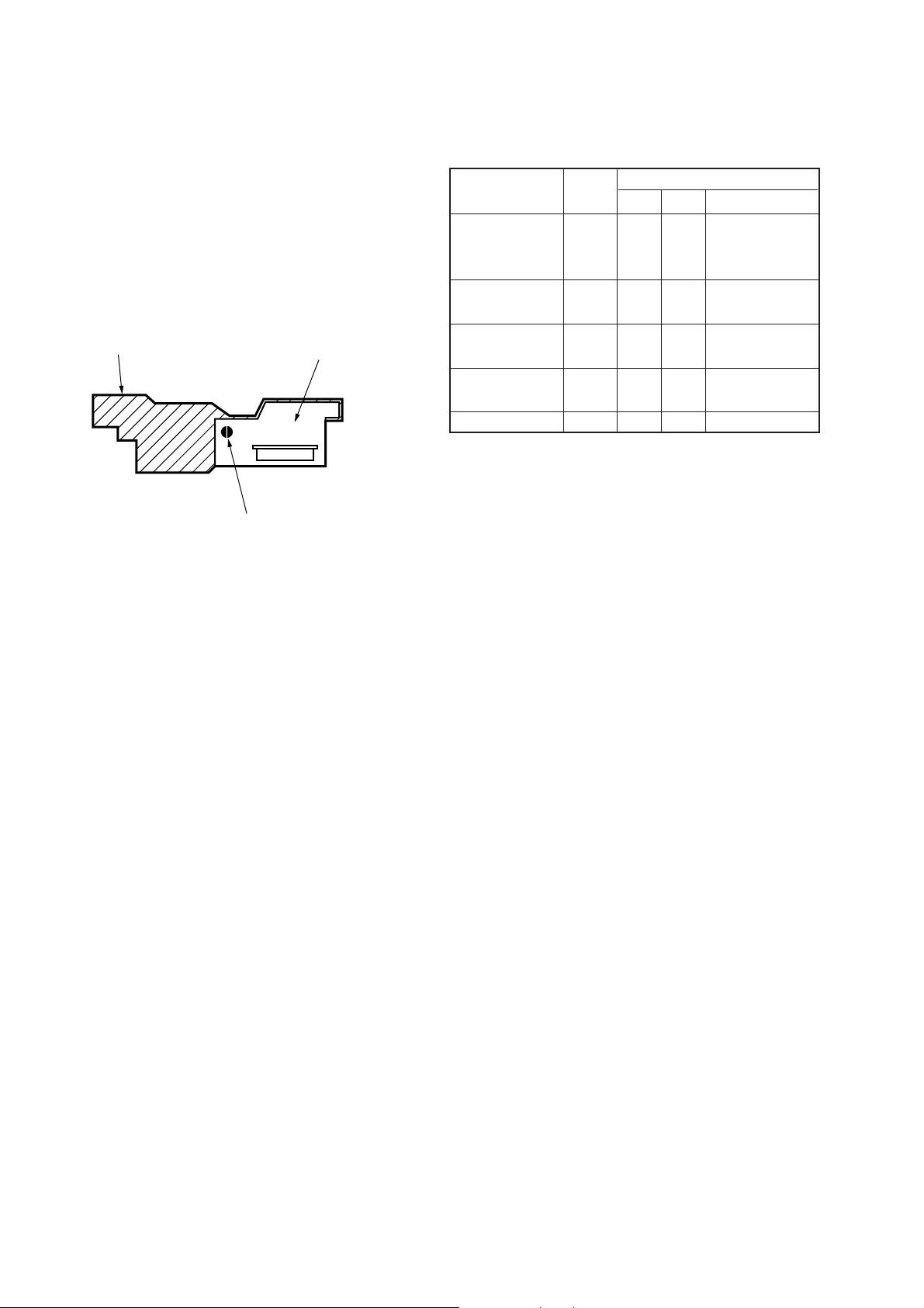
KMS
260A
27X40
B0825
N
Iop = 82.5 mA in this case
Iop (mA) = Digital voltmeter reading (mV)/1 (Ω)
(Optical pick-up label)
stop the laser emission.
(The EDIT/NO button is effective at all times to stop the laser
emission.)
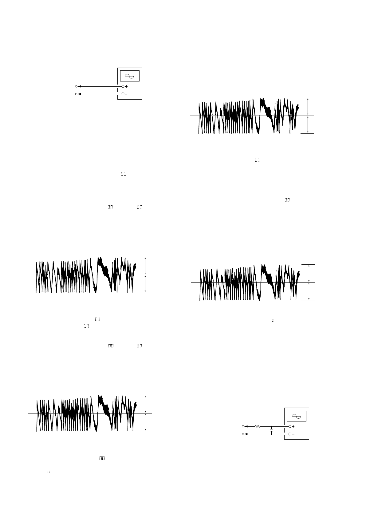
5-7. TRA VERSE ADJUSTMENT
Connection :
BD board
3
CN110 pin
CN110 pin 2 (VC)
(TEO)
Oscilloscope
11. Rotate the AMS knob until the waveform of the oscilloscope
moves closer to the specified value.
In this adjustment, waveform v aries at interv als of approx. 2%.
Adjust the waveform so that the specified value is satisfied as
much as possible.
(Traverse Wa vef orm)
V : 0.5 V/div
H : 10 ms/div
Input : DC mode
Adjusting method :
1. Connect an oscilloscope to CN110 pin 3 (TEO) and CN110
pin 2 (VC) of the BD board.
2. Load a disc (any available on the market). (Refer to Note 1.)
3. Press the 0 button or ) button and move the optical pickup outside the pit.
4. Rotate the AMS knob and display “EFBAL ADJUST”.
5. Press the YES button and display “EFB = MO-R”.
(Laser power READ power/Focus servo ON/tracking servo
OFF/spindle (S) servo ON)
6. Rotate the AMS knob so that the waveform of the oscilloscope
becomes the specified value.
(When the AMS knob is rotated, the of “EFB= ” changes
and the waveform changes.) In this adjustment, wa veform varies
at intervals of approx. 2%. Adjust the waveform so that the
specified value is satisfied as much as possible.
(Read power traverse adjustment)
(Traverse Wa v eform)
A
VC
B
Specification A = B
7. Press the YES button and save the result of adjustment to the
non-volatile memory (“EFB = SAVE” will be displayed for
a moment. Then “EFB = MO-W” will be displayed).
8. Rotate the AMS knob so that the waveform of the oscilloscope
becomes the specified value.
(When the AMS knob is rotated, the of “EFB- ” changes
and the waveform changes.) In this adjustment, wa veform varies
at intervals of approx. 2%. Adjust the waveform so that the
specified value is satisfied as much as possible.
(Write power traverse adjustment)
(Traverse Wa v eform)
A
VC
B
Specification A = B
12. Press the YES button, and save the adjustment results in the
non-volatile memory . (“EFB = SA VE” will be display ed for
a moment.)
Next “EFBAL CD” is displayed. The disc stops rotating
automatically.
13. Press the §EJECT button and remove the disc.
14. Load the check disc (MD) TDYS-1.
15. Press the YES button and display “EFB = CD”. Servo is
imposed automatically.
16. Rotate the AMS knob so that the waveform of the oscilloscope
moves closer to the specified value.
In this adjustment, waveform v aries at interv als of approx. 2%.
Adjust the waveform so that the specified value is satisfied as
much as possible.
(Traverse Wa vef orm)
A
VC
B
Specification A = B
17. Press the YES button, display “EFB = SAVE” for a moment
and save the adjustment results in the non-volatile memory.
Next “EFBAL ADJUST” will be displayed.
18. Press the §EJECT button and remove the c heck disc (MD)
TDYS-1.
Note 1 : MO reading data will be erased during if a recorded disc is
used in this adjustment.
Note 2 : If the traverse waveform is not clear, connect the
oscilloscope as shown in the following figur e so that it can
be seen more clearly.
A
VC
B
Specification A = B
9. Press the YES button, and save the adjustment results in the
non-volatile memory. (“EFB = SAVE” will be displayed
for a moment.)
10. “EFB = MO-P”. will be displayed.
The optical pick-up moves to the pit area automatically and
servo is imposed.
— 18 —
CN110 pin 3 (TEO)
BD board
CN110 pin 2 (VC)
330 k
Oscilloscope
Ω
10pF
 Loading...