

Page 1
MiniDisc Deck MDS-JB930
3-866-712-23(1)
MiniDisc Deck
Operating Instructions
Mode d’emploi
Manual de instrucciones
Manual de instruções
GB
FR
ES
PT
MDS-JB930
1999 by Sony Corporation
Page 2
WARNING
To prevent fire or shock
hazard, do not expose the
unit to rain or moisture.
This appliance is classified as a CLASS 1
LASER product.
The CLASS 1 LASER PRODUCT
MARKING is located on the rear exterior.
The following caution label is located
inside the unit.
IN NO EVENT SHALL SELLER BE
LIABLE FOR ANY DIRECT,
INCIDENTAL OR CONSEQUENTIAL
DAMAGES OF ANY NATURE, OR
LOSSES OR EXPENSES RESULTING
FROM ANY DEFECTIVE PRODUCT OR
THE USE OF ANY PRODUCT.
Welcome!
Thank you for purchasing the Sony
MiniDisc Deck. Before operating the
deck, please read this manual
thoroughly and retain it for future
reference.
About This
Manual
The instructions in this manual are for
the MDS-JB930 MiniDisc Deck.
Conventions
• Controls in these instructions are
those on the deck; these may,
however, be substituted by controls
on the supplied remote that are
similarly named, or, when different,
appear in the instructions within
parentheses.
Example: T urn AMS clockwise (or
press > repeatedly).
• The following icons are used in this
manual:
ZIndicates a procedure that
requires use of the remote.
z Indicates hints and tips for
making the task easier.
GB
2
Page 3

TABLE OF CONTENTS
Getting Started 4
Before You Start the Hookup 4
Hooking Up the Audio Components 5
Setting the Clock 8
Location and Function of Parts 10
Front Panel Parts Descriptions 10
Remote Parts Descriptions 12
Using the Display 14
Recording on MDs 17
Notes on Recording 17
Recording on an MD 18
Adjusting the Recording Level 20
Recording Tips 20
Marking Track Numbers While Recording
(Track Marking) 22
Starting Recording With Six Seconds of Prestored
Audio Data (Time Machine Recording) 23
Synchro-recording With the Audio Component of
Your Choice (Music Synchro-recording) 24
Synchro-recording With a Sony CD Player
(CD Synchro-recording) 24
Editing Recorded MDs 33
Erasing Tracks 34
Dividing Tracks 36
Combining Tracks 37
Moving Tracks 38
Naming a Track or MD 38
Undoing the Last Edit 42
Other Functions 43
Changing the Pitch (Pitch Control Function) 43
Fade In and Fade Out 44
Falling Asleep to Music (Sleep Timer) 45
Using a Timer 46
Playing With Different Tones (Digital Filter) 47
GB
Operating the MD Deck Using a
Keyboard 49
Setting the Keyboard 49
Naming a Track or MD Using the Keyboard 50
Operating the Deck Through the Keyboard 51
Assigning Characters to Keyboard Keys 52
Playing MDs 26
Playing an MD 26
Playing a Specific Track 27
Locating a Particular Point in a Track 28
Playing Tracks Repeatedly 28
Playing Tracks in Random Order (Shuffle Play) 29
Creating Your Own Programme
(Programme Play) 30
Tips for Recording From MDs to Tape 31
Additional Information 53
Precautions 53
Handling MDs 54
System Limitations 54
Troubleshooting 55
Specifications 56
Display Messages 57
Edit Menu Table 58
Setup Menu Table 58
Self-Diagnosis Function 59
Index 60
GB
3
Page 4
Getting
Before You Start the
Hookup
Started
This chapter provides information on
the supplied accessories, things you
should keep in mind while hooking
up the system, and how to connect
various audio components to the MD
deck. Be sure to read this chapter
thoroughly before you actually
connect anything to the deck.
Checking the supplied accessories
This MD deck comes with the following items:
• Audio connecting cords (2)
• Optical cable (1)
• Remote commander (remote) RM-D33M (1)
• R6 (size-AA) batteries (2)
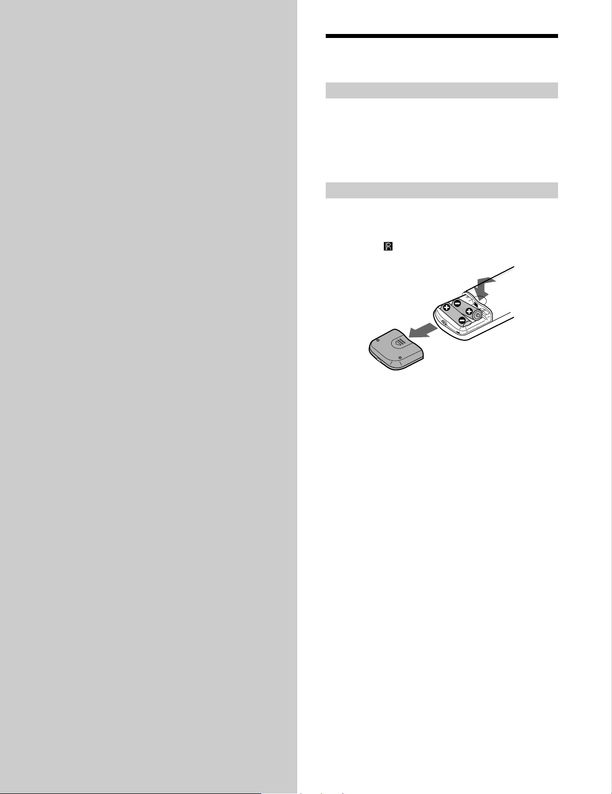
Inserting batteries into the remote
Insert two R6 (size-AA) batteries with the + and –
properly oriented to the markings into the battery
compartment. When using the remote, point it at the
remote sensor
on the deck.
z
When to replace the batteries
Under normal conditions, the batteries should last for about six
months. When the remote no longer operates the deck, replace
both batteries with new ones.
Notes
• Do not leave the remote in an extremely hot or humid place.
• Do not drop any foreign object into the remote casing,
particularly when replacing the batteries.
• Do not use a new battery with an old one.
• Do not expose the remote sensor to direct sunlight or lighting
apparatus. Doing so may cause a malfunction.
• If you don’t use the remote for an extended period of time,
remove the batteries to avoid possible damage from battery
leakage and corrosion.
GB
4
Page 5
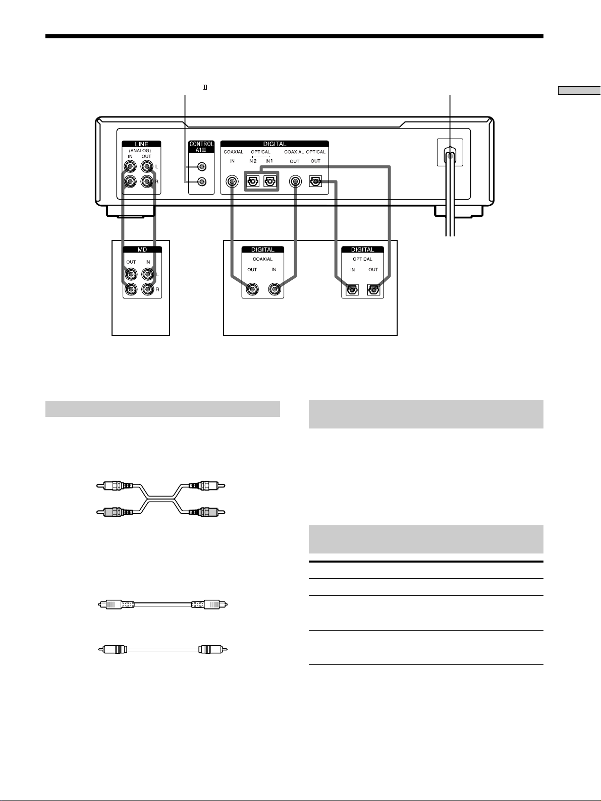
Hooking Up the Audio Components
CONTROL A1
Amplifier,
etc.
Digital equipment with a DIGITAL OUT connector only
*
Digital equipment with both DIGITAL IN and OUT connectors
**
Mains lead
Getting Started
CD player, DBS tuner*, Digital
amplifier, DAT deck, MD deck, etc.**
Required cords
Audio connecting cords (2) (supplied)
When connecting an audio connecting cord, be sure to match the
colour-coded pins to the appropriate jacks: white (left) to white
and red (right) to red.
White (L) White (L)
Red (R) Red (R)
Optical cables (3) (only one supplied)
• When connecting an optical cable, take the caps off the
connectors and insert the cable plugs straight in until they click
into place.
• Do not bend or tie the optical cables.
Coaxial digital connecting cables (2) (not supplied)
Things you should keep in mind while
hooking up the system
• Turn off the power to all components before making
any connections.
• Do not connect any mains lead until all the connections
are completed.
• Be sure the connections are firm to prevent hum and
noise.
Jacks (connectors) for connecting audio
components
Connect To the
Amplifiers LINE (ANALOG) IN/OUT jacks
CD players or DBS tuners DIGITAL COAXIAL IN jack or
Digital amplifiers, DAT decks,
or another MD deck
There is no distinction of IN1 and IN2 connectors.
*
DIGITAL OPTICAL IN
connector
DIGITAL COAXIAL IN/OUT
jacks or DIGITAL OPTICAL IN
OUT connectors
*
*/
GB
5
Page 6
Hooking Up the Audio Components
Getting Started
Connecting the mains lead
Connect the mains lead of the deck to a wall outlet.
Note
If you use a timer, connect the mains lead to the outlet of the
timer.
About the CONTROL A1 Control System
This MD deck is compatible with the CONTROL A1
Control System.
The CONTROL A1
simplify the operation of audio systems composed of
separate Sony components. CONTROL A1
provide a path for the transmission of control signals
which enable automatic operation and control features
usually associated with integrated systems.
Currently, CONTROL A1
MD deck, CD player, amplifier (receiver), and cassette
deck provide automatic function selection and synchrorecording.
In the future the CONTROL A1
a multifunction bus allowing you to control various
functions for each component.
Note
The CONTROL A1 Control System is designed to maintain
upward compatibility as the Control System is upgraded to
handle new functions. In this case, however, older components
will not be compatible with the new functions.
Control System was designed to
connections
connections between a Sony
connection will work as
CONTROL A1 and CONTROL A1 compatibility
The CONTROL A1 control system has been updated
to the CONTROL A1
which is the standard system
in the SONY 300 disc CD changer and other recent
Sony components. Components with CONTROL A1
jacks are compatible with components with
CONTROL A1
, and can be connected to each other.
Basically, the majority of the functions available with
the CONTROL A1 control system will be available
with the CONTROL A1
control system.
However, when making connections between
components with CONTROL A1 jacks and
components with CONTROL A1
jacks, the number
of functions that can be controlled may be limited
depending on the component. For detailed
information, refer to the operating instructions
supplied with the component(s).
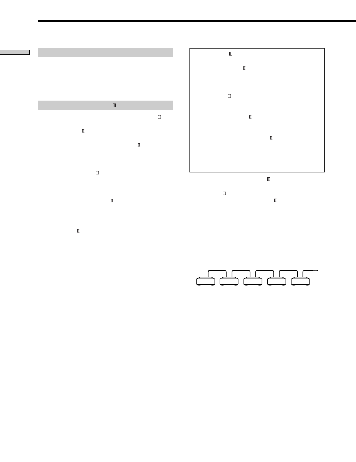
Connecting the CONTROL A1
Control System
Connect monaural (2P) mini-plug cables in series to the
CONTROL A1
can connect up to ten CONTROL A1
jacks on the back of each component. You
compatible
components in any order. However, you can connect only
one of each type of component (i.e., 1 CD player, 1 MD
deck, 1 tape deck and 1 receiver).
(You may be able to connect more than one CD player or
MD deck, depending on the model. For detailed
information, refer to the operating instructions supplied
with the respective component.)
Example
Amplifier
(Receiver)
GB
6
CD player MD deck Tape deck Other
component
Page 7
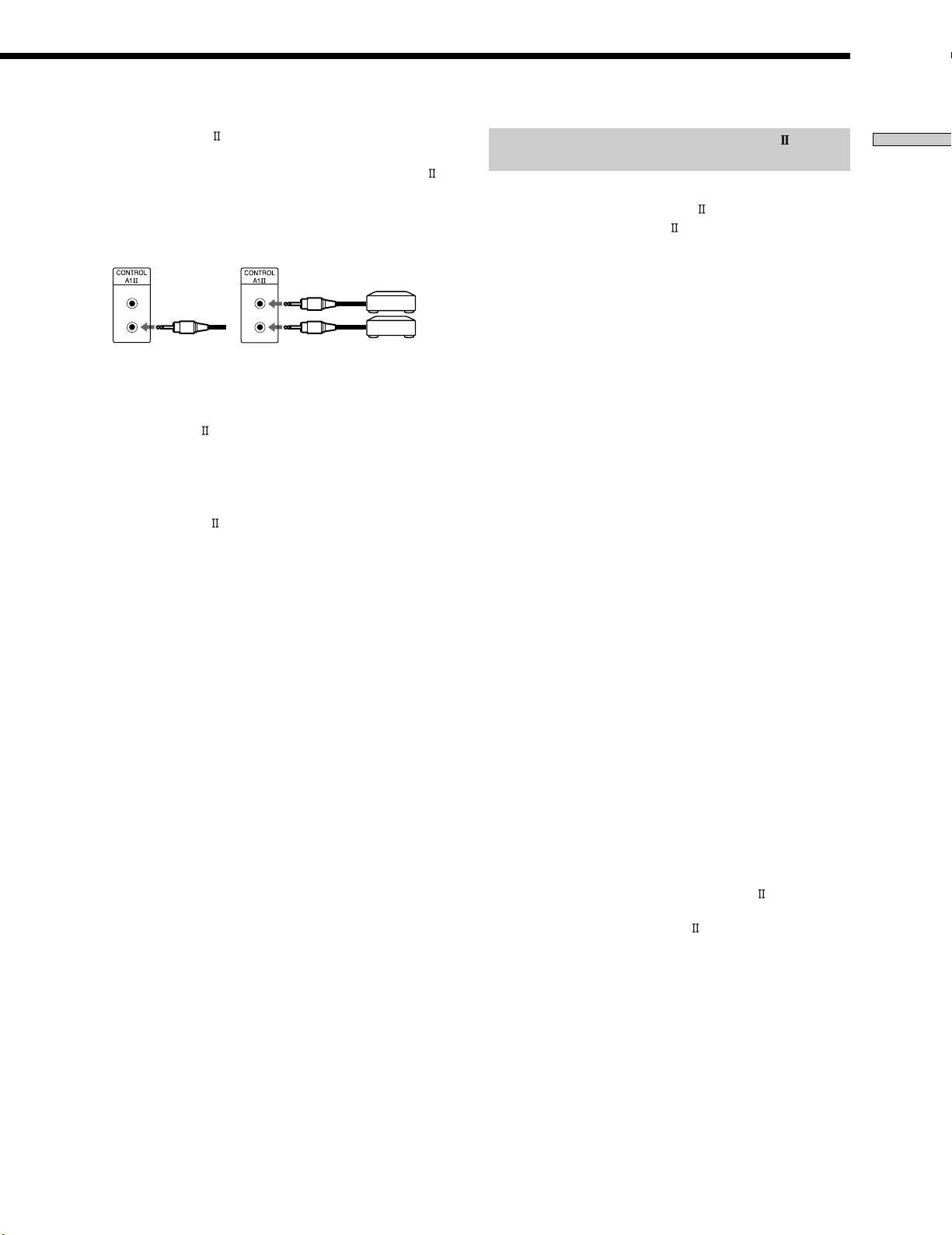
In the CONTROL A1 control system, the control signals
flow both ways, so there is no distinction of IN and OUT
jacks. If a component has more than one CONTROL A1
jack, you can use either one, or connect different
components to each jack.
Jacks and connection examples
CD player
MD deck
Basic Functions of the CONTROL A1
Control System
Automatic function selection
When you connect CONTROL A1
components using control A1
function selector on the amplifier (or receiver)
automatically switches to the correct input when you
press the play button on one of the connected
components.
(If you press H (play button) on the MD deck while the
CD is playing, the function selector on the amplifier
switches from CD to MD.)
compatible Sony
cables (not supplied), the
Getting Started
On CONTROL A1 jacks and connections
It is possible to make connections between CONTROL A1
and CONTROL A1
jacks. For details regarding
particular connections or setup options, refer to the
operating instructions supplied with component(s).
About the connecting cable
Some CONTROL A1
compatible components are
supplied with a connecting cable as an accessory. In this
case, use the connecting cable for your connection.
When using a commercially available cable, use a
monaural (2P) mini-plug cable less than 2 meters long,
with no resistance (like the Sony RK-G69HG).
Notes
• This function only works when the components are connected
to the amplifier (or receiver) inputs according to the names on
the function buttons. Certain receivers allow you to switch the
names of the function buttons. In this case, refer to the
operating instructions supplied with the receiver.
• When recording, do not play any components other than the
recording source. It will cause the automatic function selection
to operate.
Synchro-recording
This function lets you perform synchro-recording between
the MD deck and selected source component.
1 Set the source selector on the amplifier (or
receiver) to the source component.
2 Set the source component to pause mode (make
sure both the H and X indicators light together).
3 Set the deck to recording pause mode.
4 Press X on the deck.
The source component is released from the pause
mode, and recording begins shortly thereafter.
When the playback ends from the source component,
recording stops.
Notes
• Do not set more than one component to the pause mode.
• This MD deck is equipped with a special synchronized
recording function that uses the CONTROL A1 Control
System (see “Making a CD Synchro-recording from a Sony CD
player connected with a control A1 cable (not supplied)” on
page 25).
GB
7
Page 8
Setting the Clock
Getting Started
Once you set the MD deck’s internal clock, the MD deck
will automatically record the date and time of all
recordings. When playing a track, you can display the
date and time the track was recorded (see page 16).
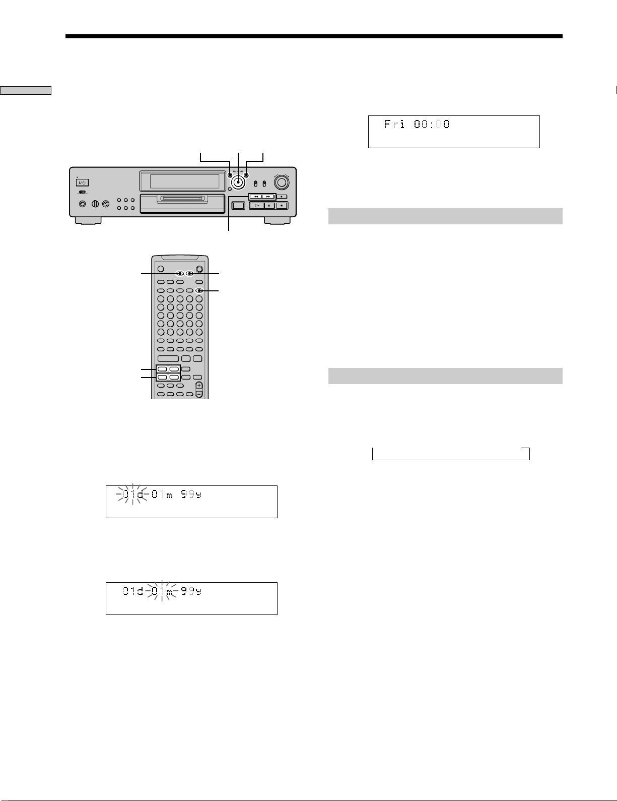
1 While the deck is stopped, press MENU/NO twice.
“Setup Menu” appears in the display.
2 Turn AMS (or press ./> repeatedly) until
“Clock Set ?” appears, then press AMS.
The day indication starts flashing.
3 Turn AMS (or press ./> repeatedly) to enter
the current day, then press AMS.
The day indication stops flashing, and the month
indication starts flashing.
./>
m/M
Z
H
>
mM
MENU/NO
` / 1
X
x
z.
>.X
AMS
AMS YES
m/M
YESMENU/NO
DATE
PRESENT
4 Repeat step 3 to enter the month, year, hour, and
minute.
When you enter the minute, the set date and time
appear again followed by “Complete!!”, and the clock
settings are completed.
A
Changing the clock setting(s)
1 Do steps 1 and 2 above.
2 Press AMS or m/M repeatedly until the setting
you want to change flashes.
3 Tur n AMS (or press ./> repeatedly) to change
the setting, then press AMS.
4 To complete the setting, press AMS or m/M
repeatedly until the minute indication flashes, then
press AMS or YES.
Displaying the current date and time Z
You can display the current date and time any time while
the power is on.
Press DATE PRESENT.
Each press of the button changes the display as follows:
t Current display t Date t Time
z
For precise date and time stamping of recordings
Reset the time at least once a week.
Note
If the mains lead is disconnected for a long time, the memorized
clock settings will disappear and “Initialize” will flash in the
display the next time you plug in and turn on the deck. If this
happens, reset the clock.
GB
8
Page 9

Getting Started
GB
9
Page 10

Location and
Function of
Parts
This chapter tells you about the
location and function of the various
buttons and controls on the front
panel and the supplied remote.
Further details are provided on the
pages indicated in the parentheses.
It also tells you about the information
that appears in the display window.
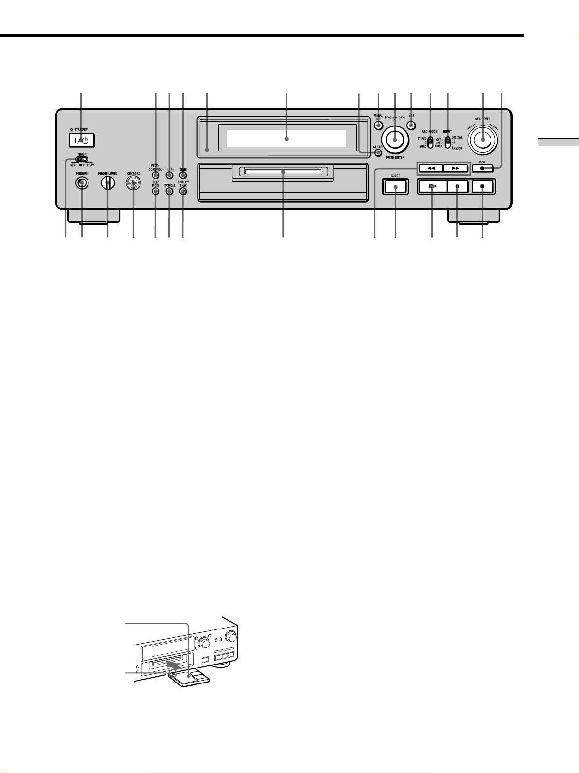
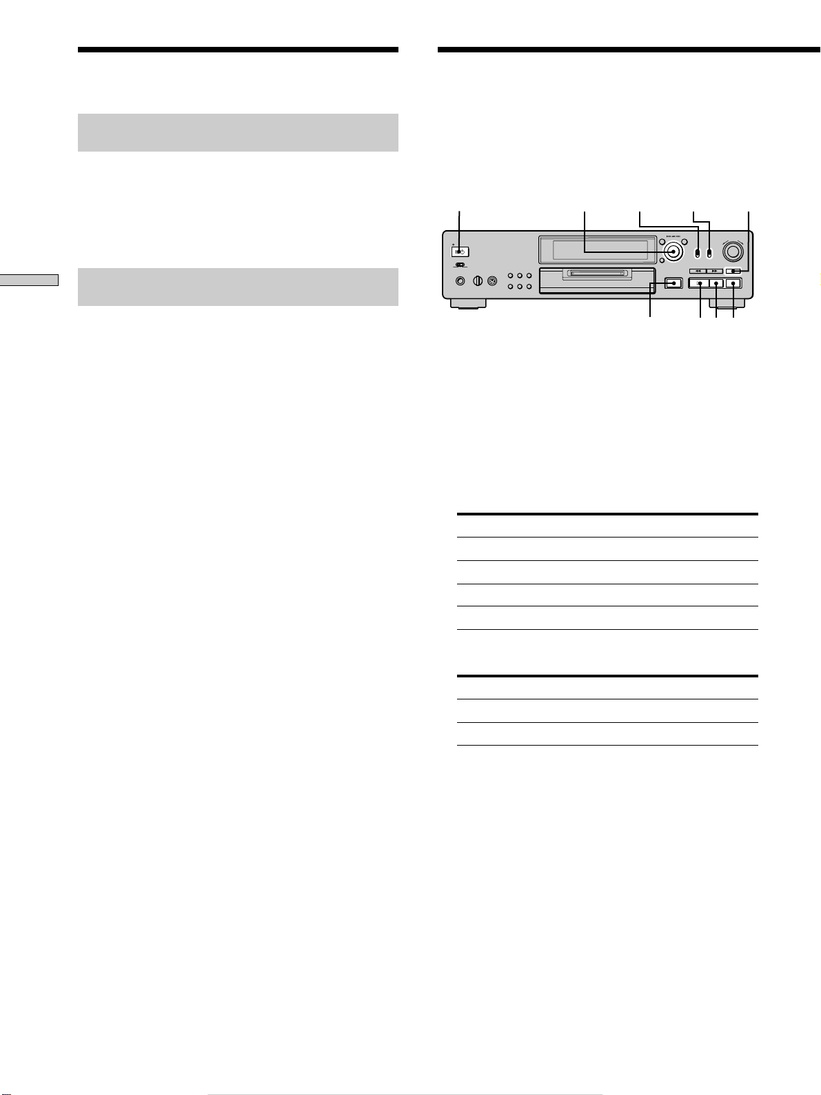
Front Panel Parts
Descriptions
1 ~/1 (power) switch (18, 26, 55, 57)
Press to turn on the deck. When you turn on the deck,
the STANDBY indicator turns off. When you press the
switch again, the deck turns off and the indicator
lights up.
2 PITCH CONTROL button (16, 43, 44)
Press to set the MD playback speed (pitch). When
you’ve set the pitch to a value other than “0” (factory
setting), the button lights amber during play.
3 FILTER button (47)
Press to select the type of the digital filter.
4 TIME button (14-16, 20, 25)
Press to display the remaining time.
5 Remote sensor (4)
Point the remote towards this sensor (
operations.
6 Display window (8, 14-16, 20, 39, 43)
Shows various information.
7 CLEAR button (30, 31, 39)
Press to cancel the selection.
8 MENU/NO button (8, 21, 22, 30-42, 45, 49)
Press to display “Edit Menu” or “Setup Menu.”
9 AMS control (8, 19, 21-23, 26, 27, 30-45, 49)
Turn to locate tracks, set the clock, select the input
characters, or select a menu item and a setting value.
q; YES button (8, 21, 22, 30-42, 45, 49)
Press to carry out the selected operation.
) for remote
10
qa REC MODE selector (18)
Use to set the REC MODE to STEREO or MONO.
GB
Page 11
234
5
6
7
8
0 qa qs
9
qd
qf1
–+
Location and Function of Parts
0
10
wj wh
qs INPUT selector (18, 20, 21, 55)
Use to select the input jack (or connector) of the
programme source to be recorded.
qd REC LEVEL control (20)
Turn to adjust the recording level.
qf REC z button (19, 20, 22, 25, 42)
Press to record on the MD, monitor the input signal, or
mark track numbers.
qg x button (19, 26, 46)
Press to stop play or recording, or cancel the selected
operation.
qh X button (7, 19, 25, 26)
Press to pause play or recording. Press again to
resume play or recording.
wg
wf
wd
wswa
A
w;
wa DISPLAY/CHAR button (14, 15, 20, 30, 39)
• Press when the deck is stopped to display disc
information or the contents of a programme.
• Press during recording to display information on the
track being recorded.
• Press during play to display information on the
current track.
• Press during recording pause to adjust the recording
level.
• Press while editing an MD to select the type of
characters to be input.
ws SCROLL button (16)
Press to scroll the name of a track or MD.
wd PLAY MODE button (29, 30, 46)
Press to select Shuffle Play or Programme Play.
ql
qk
qj
qgqh
qj H button (7, 19, 25-27, 29, 30, 46)
Press to start play.
qk EJECT A button (19, 20, 26)
Press to eject the MD.
ql m/M buttons (8, 28, 30, 31, 33, 35, 36, 39)
Press to locate a portion within a track, change the
contents of a programme, or change the input
character.
w; MD insertion slot (18, 26)
Insert the MD as illustrated below.
With the labelled
side up
With the arrow
pointing towards
the deck
wf KEYBOARD jack (49)
Connect a keyboard to this jack.
wg PHONE LEVEL control (26)
Turn to adjust the volume of the headphones.
wh PHONES jack (26)
Connect headphones to this jack.
wj TIMER selector (46)
Use to set the timer for recording (REC) or playing
(PLAY). Set to OFF to turn off the timer.
11
GB
Page 12
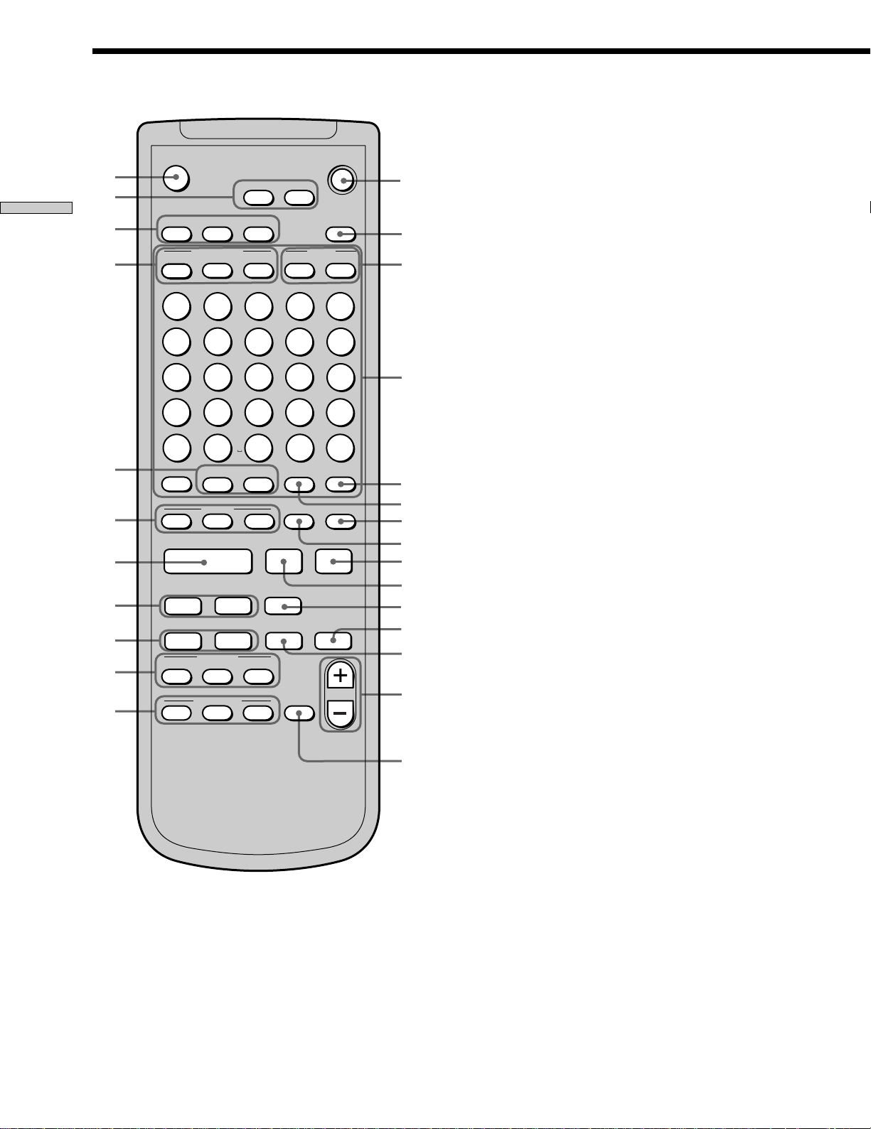
Remote Parts Descriptions
EJECT
wh
wg
Location and Function of Parts
wf
wd
Z
DISPLAY
CONTINUE
A
F
1
SCROLL
PLAY MODE
SHUFFLE
B
G
2
MENU/NO
TIME
PROGRAM
C
H
3
YES
RECORDED
D
I
4
DATE
E
J
` / 1
FILTER
PRESENT
5
1
2
3
1~/1 (power) switch (18, 26, 55, 57)
Press to turn on the deck. When you turn on the deck,
the STANDBY indicator on the deck turns off. When
you press the switch again, the deck turns off and the
indicator lights up.
2 FILTER button (47)
Press to select the type of the digital filter.
3 DATE PRESENT button (8)
Press to display the current date and time.
DATE RECORDED button (16)
Press to display the recording date and time.
ws
wa
w;
ql
qk
qj
qh
K
P
U
Z
/
11
16
21
>
NAME
7
6
Q
12
V
17
–
22
REPEAT
?
25
WRITE CLEAR
CHAR
R
13
W
18
23
AyB
!
NUM
M
L
H
.
m
X.>
>
M
CD-SYNC
STANDBYSTARTSTOP
CD PLAYER FADER
N
8
9
S
14
X
19
.
24
A.SPACE
(
X
z
T.REC MUSIC SYNC
/ANALOG OUT LEVEL
O
10
T
15
Y
20
,
25
M.SCAN
)
P.HOLD
x
REC LEVEL
4
5
6
7
8
9
0
qa
qs
qd
qf
qg
4 Letter/number buttons (16, 27, 30, 40)
Press to input letters or numbers.
5 M.SCAN button (27)
Press to scan a track within a range of six to twenty
seconds.
6 A.SPACE button (31, 32)
Press to insert a three-second blank space between
tracks or to pause play after each track.
7 P.HOLD button (15)
Press to turn on or off the Peak Hold Function.
8 CLEAR button (30, 31, 40, 41)
Press to cancel the selection.
9 x button (19, 26, 46)
Press to stop play or recording, or cancel the selected
operation.
0 X button (19, 26)
Press to pause play or recording. Press again to
resume play or recording.
qa z button (19, 20, 22, 42)
Press to record on the MD, monitor the input signal, or
mark track numbers.
qs MUSIC SYNC button (24, 42)
Press to start Music Synchro-recording.
12
GB
Page 13

qd T.REC button (23)
Press to start Time Machine Recording.
qf REC LEVEL/ANALOG OUT LEVEL +/– buttons (20, 26)
Press to adjust the recording or analog output level.
qg FADER button (44, 45)
Press to perform Fade-in Play/Recording or Fade-out
Play/Recording.
qh CD PLAYER X button (25)
Press to pause the CD play. Press again to resume CD
play.
CD PLAYER ./> buttons (25)
Press to locate tracks on the CD.
qj CD-SYNC STOP button (25)
Press to stop CD Synchro-recording.
CD-SYNC START button (24, 25)
Press to start CD Synchro-recording.
CD-SYNC STANDBY button (24, 25)
Press to enter standby for CD Synchro-recording.
qk m/M buttons (8, 28-31, 35, 36, 40)
Press to locate a portion within a track, change the
contents of a programme, or shift the cursor to the
right.
ql ./> buttons (8, 16, 19, 21, 22, 26, 27, 30-32,
34-38, 40-42, 45, 49)
Press to locate tracks or select a menu item and a
setting value.
ws REPEAT button (28, 29)
Press to play tracks repeatedly.
AyB button (29)
Press to select Repeat A-B Play.
wd CONTINUE button (29, 30, 46)
Press to resume normal play.
SHUFFLE button (29, 46)
Press to select Shuffle Play.
PROGRAM button (30, 46)
Press to select Programme Play.
wf DISPLAY button (14, 15, 20, 30)
Press to select the information to be displayed in the
window.
SCROLL button (16)
Press to scroll the name of a track or MD.
TIME button (14-16, 20, 25)
Press to display the remaining time.
wg MENU/NO button (8, 21, 22, 30-38, 40-42, 45, 49)
Press to display “Edit Menu” or “Setup Menu.”
YES button (8, 21, 22, 30-38, 40-42, 45, 49)
Press to carry out the selected operation.
wh EJECT Z button (19, 20, 26)
Press to eject the MD.
Location and Function of Parts
w; H button (19, 26, 27, 29, 30, 46)
Press to start play.
wa NAME button (40, 41)
Press to add the name or change the name of a track or
MD.
CHAR button (40)
Press to select the type of characters to be input.
NUM button (40)
Press to input numbers.
13
GB
Page 14
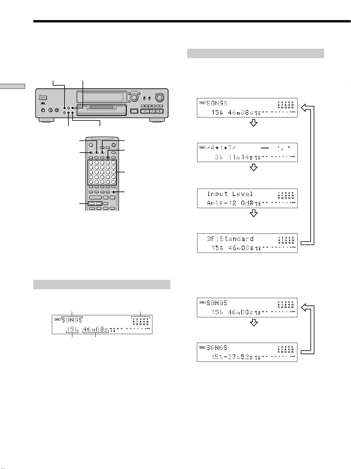
Using the Display
The display window shows information about the MD or
track. This section describes the information that appears
for each deck status.
PITCH CONTROL
TIME
Location and Function of Parts
SCROLL
SCROLL
DISPLAY
./>
DISPLAY/CHAR
Z
mM
Note
The display format that you’ve selected in each of the deck
statuses (play, recording, etc.) will appear whenever the deck
enters that status and you press DISPLAY/CHAR (or DISPLAY)
or TIME until you change the format to another (see the
following sections for details). If you disconnect the mains lead,
however, all the displays will revert to their default (i.e., the
factory set display) the next time you turn on the deck.
When you insert an MD
The following display appears.
H
While the deck is stopped
Press DISPLAY/CHAR (or DISPLAY) repeatedly to
change the display.
Each press of the button changes the display as follows:
Total number of tracks and total recorded
time (default display)
A
Press
The contents of a programme (only when
TIME
` / 1
DATE
RECORDED
Number
buttons
X
z.>
P.HOLD
x
“PROGRAM” lights up)
Press
Level of the input signal
Press
DF (digital filter) display
Press
z
You can check the remaining recordable time on the MD
Press TIME. Each press of the button changes the display as
follows:
Total number of tracks and total recorded
time (default display)
Disc name* Music calendar**
Total number
Total recorded time
of tracks
The track name appears instead of the disc name during play. When
*
the MD or the track has no name, “No Name” appears.
A music calendar shows all the track numbers within a grid if the
**
MD is a premastered disc, or without a grid if the MD is a recordable
disc. If the total number of tracks exceeds 15, B appears to the right
of number 15 in the music calendar.
GB
14
Press
Total number of tracks and remaining recordable
time on the MD (recordable MDs only)
Not shown for the premastered discs.
*
*
Press
Page 15
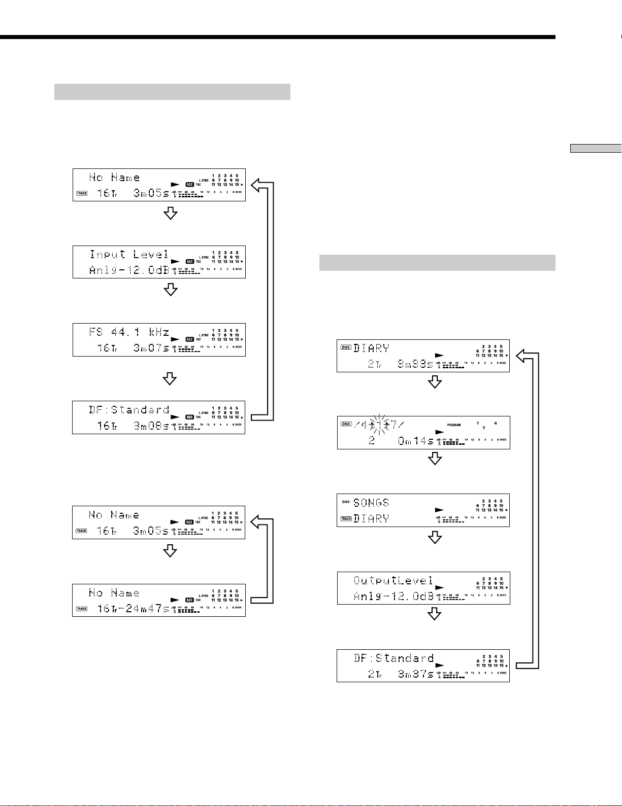
While the deck is recording
Press DISPLAY/CHAR (or DISPLAY) repeatedly to
change the display.
Each press of the button changes the display as follows:
Track number and recorded time of the
current track (default display)
Press
Level of the input signal
z
The Peak Hold Function freezes the peak level meters at the
highest level reached by the input signal
1 While the deck is stopped or playing, press MENU/NO twice.
“Setup Menu” appears in the display.
2 Turn AMS until “P.Hold Off” (factory setting) appears, then
press AMS or YES.
3 Turn AMS to select “P.Hold On,” then press AMS or YES.
4 Press MENU/NO.
To turn off the Peak Hold Function, select “P.Hold Off” in step 3
above.
z
You can use the remote to turn the Peak Hold Function on or
off Z
Press P.HOLD to display “P.Hold On” or “P.Hold Off.”
While the deck is playing
Location and Function of Parts
Press
Sampling frequency indication
“FS -- kHz” appears while the analog signal is input.
*
DF (digital filter) display
z
You can check the remaining recordable time on the MD
Press TIME. Each press of the button changes the display as
follows:
Track number and recorded time of the
current track (default display)
Track number and remaining recordable
time on the MD
*
Press
Press
Press
Press DISPLAY/CHAR (or DISPLAY) repeatedly to
change the display.
Each press of the button changes the display as follows:
Track number and elapsed time of the
current track (default display)
Press
The contents of a programme (only when
“PROGRAM” lights up)
Press
Disc name and track name
Press
Level of the output signal
Press
DF (digital filter) display
Press
Press
15
GB
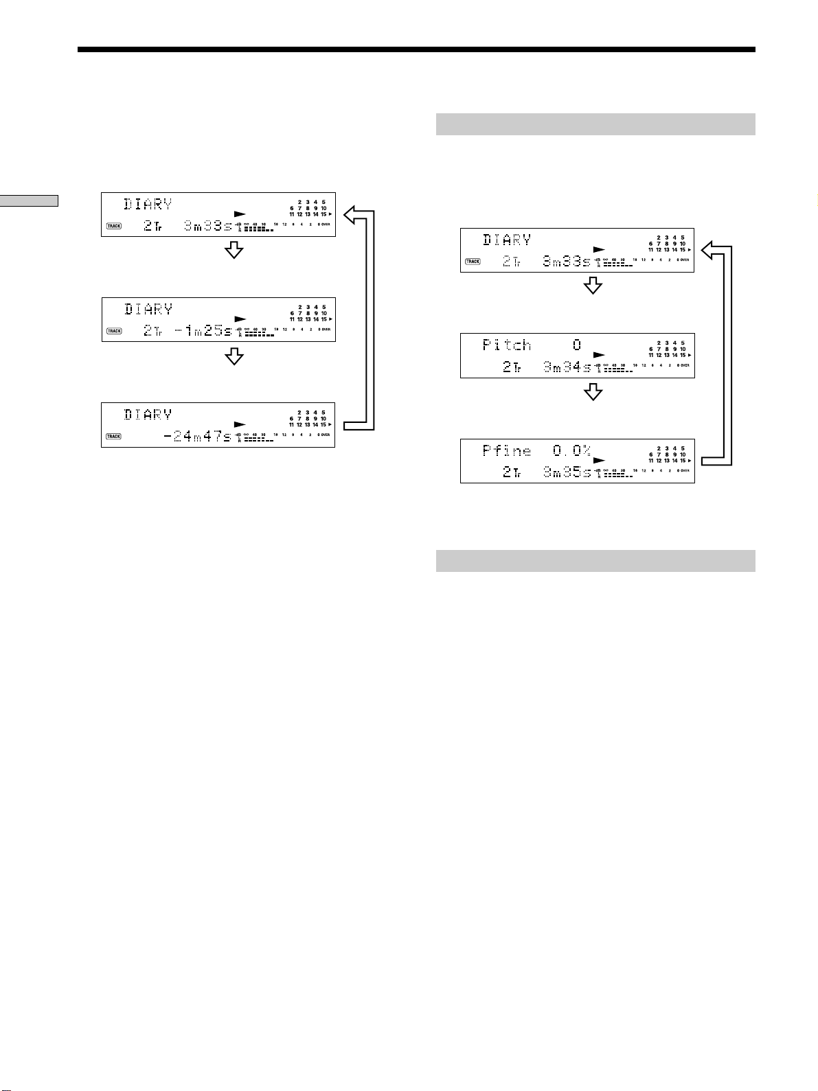
Page 16
Using the Display
z
You can check the remaining time
Press TIME. Each press of the button changes the display as
follows:
Track number and elapsed time of the
current track (default display)
Location and Function of Parts
Checking the pitch control value
Press PITCH CONTROL repeatedly to change the
display.
Each press of the button changes the display as follows:
Track number and elapsed time of the
current track (default display during play)
Press
Track number and remaining time of the
current track
Press
Remaining time of all recorded tracks
Press
z
You can check the track name at any time while playing
Press SCROLL.
The track name appears and scrolls. While the track name is
scrolling, press the button again to pause scrolling, and again to
continue scrolling.
Press
Pitch value in steps
Fine control value*
If you want to change the pitch, see “Changing the Pitch” on pages
*
43 and 44.
*
Press
Press
Displaying the recorded date Z
When the internal clock has been set, the deck
automatically records the recording date and time of all
recordings. You can then check the recorded date and
time of a track.
1 Press ./> or number buttons to locate the
track you want to check.
16
2 Press DATE RECORDED.
“No Date” appears if the internal clock has not been
set or the track was recorded on another MD deck
without a date and time stamp function.
GB
Page 17

Recording on
Notes on Recording
MDs
This chapter explains the various
ways to record on an MD, as well as
how to mark track numbers and
perform synchro-recording with other
components.
About indications which appear while
recording
When “Protected” and “C11” alternate in the
display
The record-protect slot is open and the MD is recordprotected. To record on the MD, slide the tab to close the
slot. For details, see “To prevent accidental erasure of the
recorded material” on page 19.
When “Din Unlock” and “C71” alternate in the
display
• The digital component selected with the INPUT selector
is not connected correctly. Check the connection.
• The selected digital component is not turned on. Turn
on the component.
When “Cannot Copy” appears in the display
The MD deck uses the Serial Copy Management System.
MDs recorded through the digital input connector can’t be
copied on other MDs or DAT tapes through the digital
output connector. For details, see “Guide to the Serial
Copy Management System” on page 18.
When “TRACK” flashes in the display
The MD deck is recording over existing track(s) (see
“Recording on an MD” on page 18). The indication stops
flashing when the deck reaches the end of the recorded
portion.
Recording on MDs
About indications which appear after
recording
When “TOC” lights up in the display
Recording has finished but the TOC (Table of Contents)
on the MD has not been updated to reflect the recording
results. The recording will be lost if you disconnect the
mains lead while the indication is on. The TOC will be
updated only when you eject the MD or turn off the MD
deck.
When “TOC Writing” flashes in the display
The deck is updating the TOC. Do not disconnect the
mains lead or move the deck while the indication flashes.
17
GB
Page 18
EJECT A
X
\/1
H
x
REC z
INPUT
REC MODE
AMS
Notes on Recording
Recording on an MD
Automatic conversion of digital sampling
rates during recording
A built-in sampling rate converter automatically converts
the sampling frequency of various digital sources to the
44.1 kHz sampling rate of the MD deck. This allows you
to monitor and record sources such as 32- or 48-kHz DAT
tape or satellite broadcasts, as well as the CDs and MDs.
Recording on MDs
Guide to the Serial Copy Management
System
Digital audio components, such as CDs, MDs, and DATs
make it easy to produce high-quality copies of music by
processing music as a digital signal.
To protect copyrighted music sources, this deck uses the
Serial Copy Management System which allows you to
make only a single copy of a digitally recorded source
through digital-to-digital connections.
You can make only a first-generation copy
through a digital-to-digital connection.
Examples are given as follows:
• You can make a copy of a commercially available digital
sound programme (for example, a CD or MD), but you
can’t make a second copy from the first-generation
copy.
• You can make a copy of a digital signal from a digitally
recorded analog sound programme (for example, an
analog record or a music cassette tape) or from a digital
satellite broadcast programme, but you can’t make a
second copy from the first-generation copy.
A first-generation copy means the first recording of a digital audio
*
source through the deck’s digital input connector. For example, if you
record from a CD player connected to the DIGITAL IN connector,
that copy is a first-generation copy.
Note
The restrictions of the Serial Copy Management System don’t
apply when you make a recording through the analog-to-analog
connections.
The operations for normal recording are explained below.
If the MD has recorded material on it, the deck will
automatically start recording from the end of the recorded
portion.
A
1 Turn on the amplifier and programme source, and
select the source on the amplifier.
2 Press ~/1 to turn on the deck.
The STANDBY indicator turns off.
*
3 Insert a recordable MD.
4 Set INPUT to the position that corresponds to the
input jacks (connector) connected to the
programme source.
If the source is connected to the Set INPUT to
DIGITAL OPTICAL IN1 connector OPT1
DIGITAL OPTICAL IN2 connector OPT2
DIGITAL COAXIAL IN jack COAX
LINE (ANALOG) IN jacks ANALOG
5 Set REC MODE to the recording mode you want to
record in.
To record in Set REC MODE to
Stereo STEREO
Monaural MONO
Monaural mode allows you to record about twice as
much material as stereo.
18
GB
Page 19
6 If necessary, locate the point on the MD to start
recording from.
If you want to record on a new MD or start recording
from the end of the recorded portion, go to step 7.
To record over from the beginning of an existing MD
track
Turn AMS (or press ./> repeatedly) until the
number of the track to be recorded over appears.
To record over from the middle of an MD track
Turn AMS (or press ./> repeatedly) until the
number of the track to be recorded over appears, then
press H to start playback. Press X at the point you
want to start recording from.
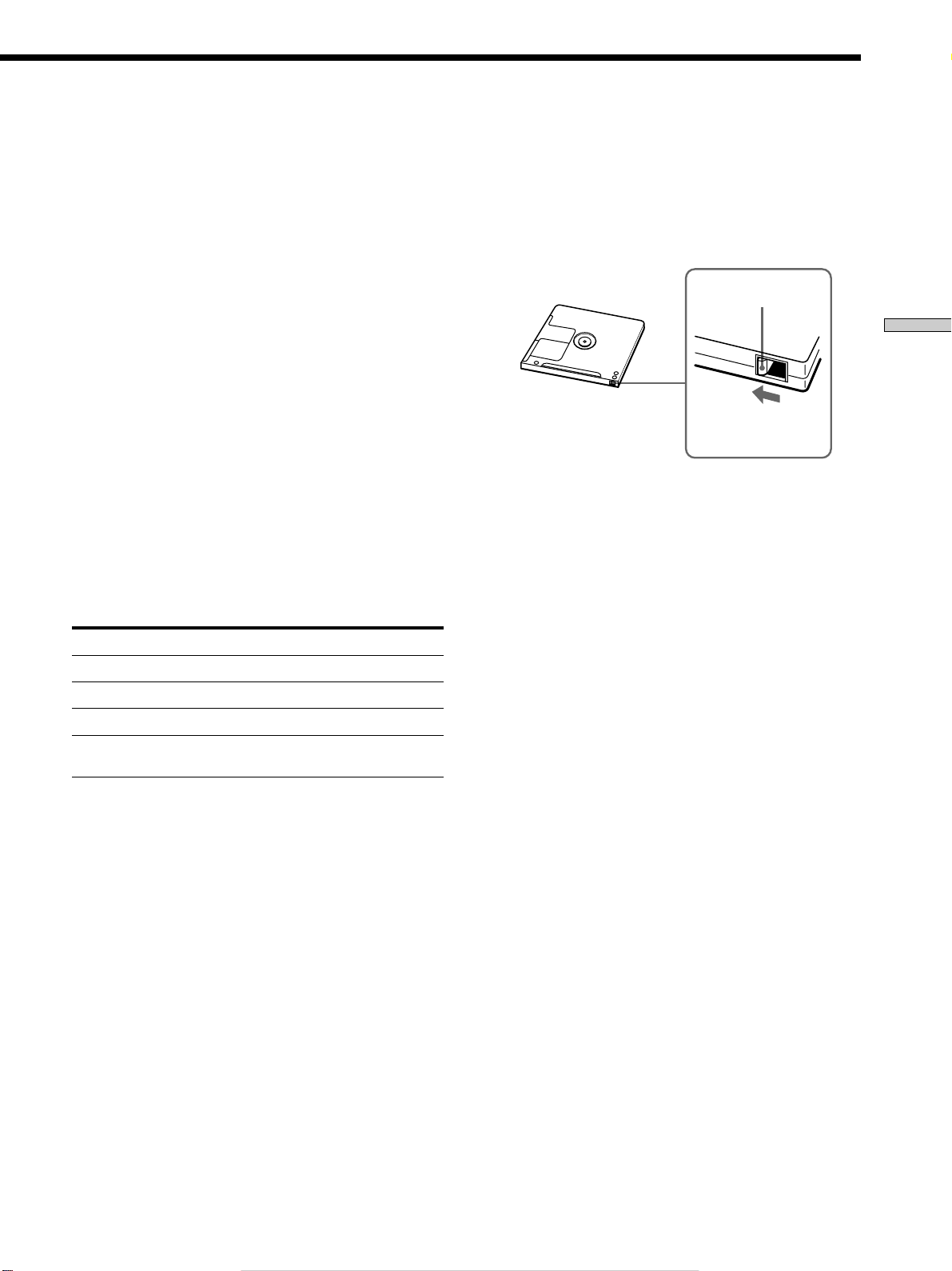
To prevent accidental erasure of the recorded
material
To make it impossible to record on an MD, slide the
record-protect tab in the direction of the arrow (see
illustration below) to open the slot. To enable recording,
close the slot.
Bottom side of the MD
Record-protect tab
Recording on MDs
7 Press REC z.
The deck changes to recording pause.
8 If necessary, adjust the recording level.
For details, see “Adjusting the Recording Level” on
page 20.
9 Press H or X.
Recording starts.
10Start playing the programme source.
Operations you may want to do during recording
To Press
Stop recording x
Pause recording X
Resume recording after pausing H or X
Eject the MD EJECT A after stopping
recording
When you pause recording
The track number increases by one. For example, if you
paused recording while recording track 4, the track
number will be 5 when you resume recording.
Slide in the direction
of arrow
z
To play the tracks you just recorded
Press H immediately after stopping recording.
The deck starts to play from the first track of the material just
recorded.
z
To play from the first track of the MD after recording
1 Press x again after stopping recording.
2 Press H.
The deck starts to play from the first track of the MD.
Notes
• If you switch REC MODE during recording or recording pause,
recording stops.
• Even if you set REC MODE to MONO, the monitor signal
during recording does not become monaural.
• You can’t record over existing material when Shuffle Play (page
29) or Programme Play (page 30) has been selected.
“Impossible” appears in the display at this time.
19
GB
Page 20

Adjusting the Recording
EJECT A
AMS
YES
MENU/NO
INPUT
REC z
TIME
Level
You can adjust the recording level for both analog and
digital recording.
Recording Tips
Recording on MDs
1 Do steps 1 to 7 of “Recording on an MD” on pages
18 and 19.
2 Play the portion of the programme source with the
strongest output.
3 Press DISPLAY/CHAR (or DISPLAY) repeatedly until
the level of the input signal appears.
4 While monitoring the sound, turn REC LEVEL (or
press REC LEVEL/ANALOG OUT LEVEL +/–
repeatedly) to raise the recording level to its
highest level without turning on the two rightmost
indicators on the peak level meters.
DISPLAY/CHAR
REC LEVEL
A
A
Checking the remaining recordable time
on the MD
Press TIME repeatedly.
While the deck is The following information appears
Stopped Total recorded time y Remaining
recordable time on the MD
Recording Recorded time of the current track y
Remaining recordable time on the MD
For details, see pages 14 and 15.
Monitoring the input signal
(Input Monitor)
You can monitor the selected input signal even when
you’re not recording it.
Avoid turning on these indicators
5 Stop playing the programme source.
6 To start recording, continue from step 9 of
“Recording on an MD” on page 19.
z
You can adjust the recording level without changing the
display
In this case, skip step 3 above.
While adjusting the recording level, the level of the input signal
appears for about three seconds.
Note
The volume can only be increased up to +12.0 dB (for analog
recording) or +18.0 dB (for digital recording). Therefore, if the
output level of the connected component is low, it may not be
possible to set the recording level to maximum.
1 Press EJECT A to eject the MD.
2 Set INPUT to the position that corresponds to the
jacks (connector) where the signal you want to
monitor is being input.
3 Press REC z.
When INPUT is set to ANALOG
The analog signal input from the LINE (ANALOG) IN
jacks is output to the DIGITAL OUT connector after
A/D conversion, and then to the LINE (ANALOG)
OUT jacks after D/A conversion. “AD - DA” appears
in the display during this time.
20
GB
Page 21

When INPUT is set to OPT1, OPT2 or COAX
The digital signal input from the DIGITAL IN
connector is output to the DIGITAL OUT connector
after passing through the sampling rate converter, and
then to the LINE (ANALOG) OUT jacks and PHONES
jack after D/A conversion. “- DA” appears in the
display during this time.
Erasing blank portions automatically
(Smart Space/Auto Cut)
The deck can be set to automatically erase any blanks that
are produced when the signal is interrupted during
recording. The function which activates (Smart Space or
Auto Cut) depends on the length of the interruption, as
described below.
Smart Space
If the signal is interrupted for less than 30 seconds, Smart
Space replaces the blank portion with a blank space of
about three seconds, then continues the recording. “Smart
Space” appears in the display during this time.
Auto Cut
If the signal is interrupted for about 30 seconds , Auto Cut
replaces the blank portion with a blank space of about
three seconds, then pauses the recording. “Auto Cut”
appears in the display during this time.
3 Turn AMS (or press ./> repeatedly) to select
the setting, then press AMS or YES.
To Select
Turn on Smart Space and Auto Cut S.Space On (factory
setting)
Turn off Smart Space and Auto Cut S.Space Off
4 Press MENU/NO.
Notes
• If you start recording with no signal input, Smart Space and
Auto Cut will not operate regardless of the setting.
• Smart Space does not affect the order of the track numbers
being recorded, even if the blank space occurs in the middle of
a track.
• Auto Cut is automatically turned on or off in tandem with
Smart Space.
• If you turn off the deck or disconnect the mains lead, the deck
will store the last setting (“S.Space On” or “S.Space Off”) and
recall it the next time you turn on the deck.
• If the deck continues recording pause for about ten minutes
after the Auto Cut activated, recording stops automatically.
Recording on MDs
Do the procedure below to turn Smart Space and Auto
Cut on or off.
1 While the deck is stopped, press MENU/NO twice.
“Setup Menu” appears in the display.
2 Turn AMS (or press ./> repeatedly) until
“S.Space On” appears, then press AMS or YES.
21
GB
Page 22

Marking Track Numbers
While Recording (Track Marking)
You can mark track numbers either manually or
automatically while recording. By marking track
numbers at specific points, you can quickly locate the
points later or edit the MD easily.
Recording on MDs
AMS
A
YESMENU/NO REC z
3 Turn AMS (or press ./> repeatedly) to select
the setting, then press AMS or YES.
To Select
Turn on Automatic Track Marking T.Mark Lsyn (factory
setting)
Turn off Automatic Track Marking T.Mark Off
4 Press MENU/NO.
The deck marks a track number whenever the input
signal level drops to –50 dB (the trigger level for
Automatic Track Marking) or below for at least 1.5
seconds.
Marking track numbers manually
(Manual Track Marking)
Press REC z at the point where you want to add a
track number while recording.
Marking track numbers automatically
(Automatic Track Marking)
When recording from a CD player or MD deck connected
to the DIGITAL IN connector, the deck marks track
numbers in the same sequence as the source. When
recording from other sources connected to the DIGITAL
IN connector or a source connected to the LINE
(ANALOG) IN jacks, do the procedure below to mark
track numbers automatically.
1 While the deck is stopped, press MENU/NO twice.
“Setup Menu” appears in the display.
2 Turn AMS (or press ./> repeatedly) until
“T.Mark Lsyn” appears, then press AMS or YES.
To change the trigger level for Automatic Track
Marking
Do the procedure below to change the signal level that
triggers Automatic Track Marking.
1 While the deck is stopped, press MENU/NO twice.
“Setup Menu” appears in the display.
2 Turn AMS (or press ./> repeatedly) until
“LS(T)” appears, then press AMS or YES.
3 Turn AMS (or press ./> repeatedly) to select
the level, then press AMS or YES.
You can set the level at any value between –72 dB and
0 dB, in 2 dB steps.
4 Press MENU/NO.
22
GB
Page 23

z
AMS
Additional information on Automatic Track Marking
• When recording from a CD player or MD deck connected to the
DIGITAL IN connector, the entire material may be recorded as
a single track in the following cases:
— When you consecutively record the same track two or more
times using single-track repeat play.
— When you consecutively record two or more tracks with the
same track number but from different CDs or MDs.
— When you record tracks from certain CD or multi-disc
players.
Also, if the source is an MD, a track number may not be
marked for tracks less than four seconds long.
• When recording from a component connected to the LINE
(ANALOG) IN jacks with “T.Mark Off” selected or when
recording from a DAT deck or DBS tuner connected to the
DIGITAL IN connector, the entire material may be recorded as
a single track.
• When recording from a DAT deck or DBS tuner connected to
the DIGITAL IN connector, the deck will mark a track number
whenever the sampling frequency of the input signal changes,
regardless of the track marking parameter setting (“T.Mark
Lsyn” or “T.Mark Off”).
z
You can mark track numbers even after recording has
finished
See “Dividing Tracks” on page 36.
Note
If you turn off the deck or disconnect the mains lead, the deck
will store the last settings (“T.Mark Lsyn” or “T.Mark Off” and
the trigger level) and recall them the next time you turn on the
deck.
Starting Recording With Six
Seconds of Prestored Audio
Data (Time Machine Recording)
Whenever the deck is in recording pause, the deck’s
buffer memory continuously stores the latest six seconds
worth of audio data. When you press AMS (or T.REC),
the recording then starts with the data in the buffer
memory. Time Machine Recording thus allows you to
avoid missing the beginning of material recorded live
from an FM or satellite broadcast.
Recording on MDs
A
1 Do steps 1 to 7 of “Recording on an MD” on pages
18 and 19.
The deck changes to recording pause.
2 Start playing the programme source.
3 Press AMS (or T.REC) at the point where you want
to start recording.
Recording starts with the six seconds of prestored data
in the buffer memory, then continues recording via the
buffer memory thereafter.
To stop Time Machine Recording
Press x.
Note
The storage of data in the buffer memory starts from the moment
the deck changes to recording pause. Thus, if you start recording
less than six seconds after changing to recording pause, less than
six seconds worth of data will be recorded from the buffer
memory. The same is true if the programme source had been
playing for less than six seconds at the time you start recording.
23
GB
Page 24

Synchro-recording With the
CD-SYNC STANDBY
CD PLAYER ./>
CD-SYNC START
CD-SYNC STOP
CD PLAYER X
TIME
>.X
H
X
` / 1
Z
x
z.
>
mM
Synchro-recording With a
Audio Component of Your
Choice (Music Synchro-recording)
Z
The Music Synchro-recording allows you to automatically
synchronize recording on the MD deck with the playing
of the selected programme source. The Track Marking
function, however, will differ according to the programme
source. For details, see “Marking Track Numbers While
Recording” on page 22.
Recording on MDs
Z
H
>
mM
Sony CD Player
(CD Synchro-recording) Z
When the deck is connected to a Sony CD player or Hi-Fi
component system, you can easily copy the contents of
CDs to the MD using the deck’s remote. As the same
remote operates both the MD deck and the CD player or
CD player section of the component system, make sure to
place the MD deck and the CD player as close together as
possible.
` / 1
X
x
z.
>.X
MUSIC SYNC
1 Do steps 1 to 6 of “Recording on an MD” on pages
18 and 19.
2 Press MUSIC SYNC.
The deck changes to recording pause.
3 Start playing the programme source.
Recording starts automatically.
To stop Music Synchro-recording
Press x.
Note
During Music Synchro-recording, Smart Space and Auto Cut will
operate regardless of their setting (“S.Space On” or “S.Space
Off”).
1 Turn on the amplifier and the CD player, and select
CD on the amplifier.
2 Do steps 2 to 6 of “Recording on an MD” on pages
18 and 19.
3 Insert a CD into the CD player and select the
playback mode (Shuffle Play, Programme Play, etc.)
on the CD player.
4 Press CD-SYNC STANDBY.
The CD player changes to play standby and the MD
deck changes to recording standby.
5 Press CD-SYNC START.
The deck starts recording and the CD player starts to
play.
The track number and elapsed recording time of the
track appear in the display.
If the CD player doesn’t start playing
Some CD players may not respond when you press
CD-SYNC START. Press X on the CD player’s remote
instead to start play on the CD player.
24
GB
Page 25

Operations you may want to do during CD
Synchro-recording
To Press
Stop recording CD-SYNC STOP
Pause recording CD-SYNC STANDBY or CD
Locate the next track to be
recorded during recording
pause
Resume recording after
pausing
Check the remaining
recordable time on the MD
z
You can use the remote of the CD player during CD Synchro-
recording
PLAYER X
CD PLAYER ./>
CD-SYNC START or CD
PLAYER X
TIME (page 15)
Press To change the deck to And change the CD player to
H Recording Play
x Recording pause Stop
X Recording pause Pause
z
During CD Synchro-recording, track numbers are marked in
the following ways:
• When the CD player is connected to the DIGITAL IN connector,
track numbers are automatically marked as they appear on the
CD.
• When the CD player is connected to the LINE (ANALOG) IN
jacks, track numbers are automatically marked when “T.Mark
Lsyn” has been selected (page 22).
• When you resume recording after recording pause, a new track
number is automatically marked, regardless of the track
marking parameter setting (“T.Mark Lsyn” or “T.Mark Off”).
z
You can change CDs during CD Synchro-recording
1 Press x on the CD player’s remote.
2 Change the CD.
3 Press H on the CD player’s remote.
Recording resumes.
z
You can also perform synchro-recording with a Sony video
CD player
By reprogramming the MD’s remote, you can use the procedure
above to perform synchro-recording with a Sony video CD
player.
Press number button 2 while pressing down ~/1 on the MD
deck’s remote. You can now operate the MD deck and the video
CD player with the remote. To control the CD player again, press
number button 2 while pressing down ~/1 on the MD deck’s
remote.
z
During CD Synchro-recording, the deck copies CD text
information (CD text and disc memos) as it is to the MD (Disc
Memo Copy function)
The Disc Memo Copy function operates when you make a CD
Synchro-recording from a Sony CD player connected with a
control A1 cable (not supplied) to the MD deck.
Notes
• When performing CD Synchro-recording with a CD player
with a mode selector, be sure to set the selector to CD1.
• When you record tracks from certain CD or multi-disc players,
the entire material may be recorded as a single track.
• The Disc Memo Copy function may not operate for extremely
short CD tracks.
• Text information may not be copied for some CDs.
Making a CD Synchro-recording from a
Sony CD player connected with a control
A1 cable (not supplied)
1 Do steps 1 to 3 of “Synchro-recording With a Sony
CD Player” on page 24.
2 Set the CD player to playback pause mode.
3 Press REC z on the deck.
The MD deck changes to recording pause.
4 Press H or X on the deck.
The deck starts recording and the CD player starts to
play. When CD play finishes, recording stops.
Recording on MDs
25
GB
Page 26

Playing MDs
AMS
XxH
`/1
EJECT A
Playing an MD
This chapter explains the various
ways to play MDs.
The operations for normal play are explained below.
A
1 Turn on the amplifier and select MD on the
amplifier.
2 Press ~/1 to turn on the deck.
The STANDBY indicator turns off.
3 Insert an MD.
4 If necessary, turn AMS clockwise (or press >
repeatedly) to locate the track you want to start
playing from.
If you want to play from the first track, go to step 5.
5 Press H.
The deck starts to play.
6 Adjust the volume on the amplifier.
Operations you may want to do during play
To Press or turn
Stop play x
Pause play X
Resume play after pausing H or X
Locate a succeeding track AMS clockwise (or press >
Locate the beginning of the
current track or a preceding
track
Eject the MD EJECT A after stopping play
Adjust the analog output
level* (between –20.0 dB and
0.0 dB) Z
When you eject the MD or turn off the deck, the output level is reset
*
to the factory setting (0.0 dB).
z
To use headphones
Connect them to PHONES jack. Turn PHONE LEVEL (or press
REC LEVEL/ANALOG OUT LEVEL +/– repeatedly) to adjust
the volume.
repeatedly)
AMS counterclockwise (or press
. repeatedly)
REC LEVEL/ANALOG OUT
LEVEL +/– repeatedly
26
GB
Page 27

Playing a Specific Track
>.X
H
X
` / 1
Z
x
A
z.
>
mM
While the deck is playing or stopped, use the procedure
below to quickly play any track.
Number
buttons
AMS
>25
M.SCAN
H
./>
z
You can change the duration of Music Scan
1 While the deck is stopped, press MENU/NO twice.
“Setup Menu” appears in the display.
2 Turn AMS (or press ./> repeatedly) until “M.Scan”
appears, then press AMS or YES.
3 Turn AMS (or press ./> repeatedly) to select the
duration, then press AMS or YES. You can set the duration
within a range of six to twenty seconds, in one step.
4 Press MENU/NO.
Playing a track by entering the track
number Z
Press the number button(s) to enter the track number
of the track you want to play.
To enter a track number over 25
Playing MDs
H
Locating a track with AMS*
To go to Do the following:
The next or a succeeding track
during play
A preceding track during play Turn AMS counterclockwise (or
The beginning of the current
track during play
A specific track while the deck
is stopped
A specific track by scanning
each track for six to twenty
seconds (Music Scan) Z
Automatic Music Sensor
*
z
To locate the last track of the MD quickly
While the deck is stopped, turn AMS counterclockwise (or press
. once).
Turn AMS clockwise (or press
> repeatedly).
press . repeatedly).
Turn AMS counterclockwise (or
press . once).
Turn AMS (or press ./>
repeatedly) until the track
number you want to go to flashes
in the display, then press AMS or
H.
Press M.SCAN to start scanning.
When you find the track you
want, press H to start playing.
1 Press >25.
2 Enter the corresponding digits.
To enter 0, press 10 instead.
Examples:
• To play track number 30, press >25, then 3 and 10.
• To play track number 108, press >25 twice, then 1, 10, and
8.
z
If you enter a track number while the deck is stopped or
paused
The deck will still be stopped or paused at the beginning of the
track.
z
If you locate a track while the deck is stopped or paused
The deck will still be stopped or paused at the beginning of the
located track.
27
GB
Page 28

Locating a Particular Point
M
>.X
H
X
` / 1
Z
x
z.>
m
REPEAT
AyB
M
Playing Tracks Repeatedly
in a Track
You can locate a particular point in a track during play or
play pause.
Locating a point while monitoring the
sound
Playing MDs
Press down m/M during play.
You will hear intermittent playback as the disc goes
forward or in reverse. When you reach the point, release
the button.
Notes
• If the disc reaches the end while you’re pressing M, the deck
stops.
• Tracks that are only a few seconds long may be too short for
monitoring. For such tracks, play the MD at normal speed.
Locating a point by observing the time
indication
Press down m/M during play pause.
The elapsed playing time of the track appears in the
display. When you reach the point, release the button.
No sound is output during this time.
z
When “- Over -” appears in the display
The disc has reached the end while you’re pressing M. Turn
AMS counterclockwise (or press .) or press m to go back.
m/M
A
Z
You can play an entire MD repeatedly. This function can
be used with Shuffle Play to repeat all the tracks in
random order (page 29), or with Programme Play to
repeat all the tracks in the programme (page 30). You can
also repeat a specific track or portion within a track.
Note
If you turn off the deck or disconnect the mains lead, the deck
will store the last setting of the repeat play (“Repeat All” or
“Repeat 1”) and recall it the next time you turn on the deck.
Repeating all the tracks on the MD
(Repeat All Play)
Press REPEAT repeatedly until “Repeat All” appears in
the display.
When you play an MD, the deck repeats the tracks as
follows:
When the play mode is The deck repeats
Normal play (page 26) All the tracks in sequence
Shuffle Play (page 29) All the tracks in random order
Programme Play (page 30) All the tracks in the programme in
sequence
To stop Repeat All Play
Press x.
To resume normal play
Press REPEAT repeatedly until “Repeat Off” appears in
the display.
28
GB
Page 29

PLAY MODE H
Repeating the current track
(Repeat 1 Play)
While the track you want to repeat is being played,
press REPEAT repeatedly until “Repeat 1” appears in
the display.
Repeat 1 Play starts.
To stop Repeat 1 Play
Press x.
Playing Tracks in Random
Order (Shuffle Play)
When you select Shuffle Play, the deck plays all the tracks
on the MD in random order.
A
To resume normal play
Press REPEAT repeatedly until “Repeat Off” appears in
the display.
Repeating a specific portion within a
track (Repeat A-B Play)
You can specify one portion within a track to be played
repeatedly. Note that the portion that you specify must be
within the boundaries of a single track.
1 While the deck is playing, press AyB at the
starting point (point A) of the portion to be played
repeatedly.
“REPEAT A-” lights up and “B” flashes in the display.
2 Continue playing the track or press M to locate
the ending point (point B), then press AyB.
“REPEAT A-B” lights up and Repeat A-B Play starts.
To stop Repeat A-B Play and resume normal play
Press REPEAT or CLEAR.
z
You can set a new starting point and ending point during
Repeat A-B Play
You can change the current ending point to a new starting point,
then specify a new ending point to repeat a portion right after the
current portion.
1 During Repeat A-B Play, press AyB.
The current ending point changes to the new starting point
(point A).
“REPEA T A-” lights up and “B” flashes in the display.
2 Locate the new ending point (point B) and press AyB.
“REPEA T A-B” lights up and the deck starts to repeat the
newly specified portion.
1 While the deck is stopped, press PLAY MODE
repeatedly (or SHUFFLE once) until “SHUFFLE”
lights up in the display.
2 Press H.
Shuffle Play starts.
; appears while the deck is “shuffling” the tracks.
To resume normal play
While the deck is stopped, press PLAY MODE repeatedly
(or CONTINUE once) until “SHUFFLE” turns off.
z
You can locate tracks during Shuffle Play
Turn AMS (or press ./> repeatedly).
• To locate the next track or a later track to be played, turn AMS
clockwise (or press > repeatedly).
• To locate the beginning of the current track, turn AMS
counterclockwise (or press .). Note that you can’t locate
and play the tracks that have already been played once.
Playing MDs
29
GB
Page 30

Creating Your Own
Programme (Programme Play)
You can pick out the tracks that you like and specify the
playback order in a programme containing up to 25
tracks.
PLAY MODE
Playing MDs
Programming the tracks
1 While the deck is stopped, press MENU/NO twice.
“Setup Menu” appears in the display.
2 Turn AMS (or press ./> repeatedly) until
“Program ?” appears, then press AMS or YES.
DISPLAY/CHAR
DISPLAY
>25
H
./>
m/M
To enter a track number over 25 Z
Use >25. For details, see page 27.
To check the total playing time of the programme
AMS
YESMENU/NO
m/M
Press DISPLAY/CHAR (or DISPLAY).
4 Repeat step 3 to enter other tracks.
The entered track is added to the location where the
“0” flashes.
Each time you enter a track, the total programme time
A
appears in the display.
5 Press YES.
CLEAR
Z
H
.
m
` / 1
X
x
>
z
M
>.X
H
MENU/NO
YES
PROGRAM
Number
buttons
CLEAR
“Complete!!” appears and the programme is
completed.
6 Press PLAY MODE repeatedly (or PROGRAM once)
until “PROGRAM” lights up in the display.
7 Press H.
Programme Play starts.
To stop Programme Play
Press x.
To resume normal play
Press PLAY MODE repeatedly (or CONTINUE once) until
“PROGRAM” turns off.
z
The programme remains even after Programme Play ends or
is stopped
Press H to play the programme again.
Notes
• If you turn off the deck or disconnect the mains lead, the
programme will be lost.
• The display shows “- - - m - - s” when the total playing time of
the programme exceeds 199 minutes.
• “ProgramFull!” appears when you try to programme the 26th
track.
3 Turn AMS (or press ./> repeatedly) until the
track number you want to add to the programme
appears, then press AMS or M (or use the number
button(s) to enter the track directly).
If you entered the wrong track number
Press m/M repeatedly until the wrong track
number flashes, then do step 3 above again or press
CLEAR to erase the track number. If “0” flashes, press
m.
GB
30
Checking the contents of the programme
While the deck is stopped and “PROGRAM” lights up,
press DISPLAY/CHAR (or DISPLAY) repeatedly.
The first several tracks in the programme appear in the
display. To see the rest of the programme, turn AMS (or
press ./> repeatedly).
Page 31

Changing the contents of the programme
AMS
YES
MENU/NO
While the deck is stopped and “PROGRAM” lights up, do
steps 1 and 2 of “Programming the tracks” on page 30,
followed by one of the procedures below:
To Do the following:
Erase a track
Erase all tracks
Add a track at the
beginning of the
programme
Add a track in the
middle of the
programme
Add a track to the
end of the
programme
Replace a track Press m/M repeatedly until the
Press m/M repeatedly until the
number of the unwanted track flashes,
then press CLEAR.
Press CLEAR repeatedly until all the track
numbers disappear.
Press m repeatedly until “0” flashes
before the first track number, then do steps
3 to 5 of “Programming the tracks” on
page 30.
Press m/M repeatedly until the track
number which will precede the new track
flashes. Press AMS to display flashing
“0, ” then do steps 3 to 5 of “Programming
the tracks” on page 30.
Press M repeatedly until “0” flashes after
the last track number, then do steps 3 to 5
of “Programming the tracks” on page 30.
number of the track to be changed flashes,
then do steps 3 to 5 of “Programming the
tracks” on page 30.
Tips for Recording From
MDs to Tape
A
Inserting blanks between tracks during
play (Auto Space)
The MD deck can be set to automatically insert a threesecond blank between tracks during play. This function is
useful when you’re recording from an MD to an analog
tape since the three-second blank enables you to use the
Multi-AMS function later to locate the beginning of tracks
on the tape.
1 While the deck is stopped, press MENU/NO twice.
“Setup Menu” appears in the display.
2 Turn AMS until “Auto Off” appears, then press
AMS or YES.
3 Turn AMS to select the setting, then press AMS or
YES.
To Select
Turn on Auto Space Auto Space
Turn off Auto Space Auto Off (factory setting)
Playing MDs
4 Press MENU/NO.
z
You can use the remote to turn Auto Space on or off Z
While the deck is stopped, press A.SPACE repeatedly until “Auto
Space” or “Auto Off”appears in the display.
Notes
• If you select “Auto Space” and record a selection containing
multiple track numbers (for example, a medley or symphony),
blank spaces will be created on the tape in between the various
sections.
• If you turn off the deck or disconnect the mains lead, the deck
will store the last setting (“Auto Space” or “Auto Off”) and
recall it the next time you turn on the deck.
31
GB
Page 32

Tips for Recording From MDs to Tape
Pausing after each track (Auto Pause)
You can set the MD deck so that it pauses after each track
to give you time to locate the next track to be recorded.
1 While the deck is stopped, press MENU/NO twice.
“Setup Menu” appears in the display.
2 Turn AMS until “Auto Off” appears, then press
AMS or YES.
3 Turn AMS to select the setting, then press AMS or
YES.
To Select
Turn on Auto Pause Auto Pause
Playing MDs
Turn off Auto Pause Auto Off (factory setting)
4 Press MENU/NO.
To resume play after pausing
Press H.
z
You can use the remote to turn Auto Pause on or off Z
While the deck is stopped, press A.SPACE repeatedly until “Auto
Pause” or “Auto Off” appears in the display.
Note
If you turn off the deck or disconnect the mains lead, the deck
will store the last setting (“Auto Pause” or “Auto Off”) and recall
it the next time you turn on the deck.
32
GB
Page 33

Editing
AMS YES
MENU/NO
m/M
Recorded MDs
This chapter explains how to edit the
tracks that have been recorded on an
MD.
A
Brief descriptions of buttons and control
used to edit MDs
The buttons and the contr ol below ar e used to erase,
divide, move, or combine tracks on the MD.
Note
The operation of these buttons and the control is different when
naming a track or MD. For details, see “Naming a Track or MD”
on page 38.
MENU/NO button: While the deck is stopped, playing,
or paused, pr ess to edit tracks. While editing, pr ess to
cancel editing.
AMS control: T urn to select an editing operation or track
number, then pr ess to enter your selection. Y ou can also
use the contr ol to specify points in a track for erasur e or
track division.
YES button: Press this button instead of the AMS contr ol
to enter a selection.
Editing Recorded MDs
m/M buttons: Press to specify the unit (minute,
second, or frame) by which the MD is advanced when the
AMS control is tur ned. You can also use these buttons to
locate the end point of the portion to be erased.
For further details on the function of each button and
control, see the sections on editing operations.
33
GB
Page 34

About indication which appears while
AAA BBB CCC DDD
1 2 3 4
AAA CCC DDD
1 2 3
editing
When “Protected” appears in the display
The recor d-protect slot is open. T o edit the MD, slide the
tab to close the slot. For details, see “T o prevent
accidental erasur e of the r ecorded material” on page 19.
About indications which appear after
editing
Erasing Tracks
Y ou can erase a track or par t of a track simply by
specifying the number of the track or the portion within a
track to be erased. Y ou can also erase all the tracks on an
MD at one time.
Erasing a track
Editing Recorded MDs
When “TOC” lights up in the display
Editing has finished but the TOC (T able of Contents) on
the MD has not been updated to r eflect the editing r esults.
The editing will be lost if you disconnect the mains lead
while the indication is on. The TOC will be updated only
when you eject the MD or tur n off the MD deck.
When “TOC Writing” flashes in the display
The deck is updating the TOC. Do not disconnect the
mains lead or move the deck while the indication flashes.
Specify the number of the track you want to erase.
Example: Erasing the second track
When you erase a track, all the tracks after the one erased
are automatically r enumber ed. For example, if you erase
track number 2, the pr evious track number 3 becomes
track number 2 and the pr evious track number 4 becomes
track number 3, and so on.
1 While the deck is stopped, playing, or paused,
press MENU/NO.
“Edit Menu” appears in the display .
2 Turn AMS (or press ./> repeatedly) until “Tr
Erase ?” appears, then press AMS or YES.
The deck starts to play the track indicated by the
number in the display .
3 Turn AMS (or press ./> repeatedly) until the
track number you want to erase appears.
GB
34
4 Press AMS or YES.
“Complete!!” appears for a few seconds and the track
is erased. The track following the erased track starts
to play. If the erased track is the last one on the MD,
the track pr eceding the erased track star ts to play .
To cancel the operation
Press MENU/NO or x.
Page 35

z
If “Erase ???” appears in step 4 above
The track has been record-protected on another MD deck. If you
still want to erase the track, press AMS or YES again while the
indication appears.
z
To avoid confusion when erasing more than one track
Start erasing from the highest numbered track. This way you’ll
avoid renumbering the tracks that you plan to erase.
z
You can undo the erasure
For details, see “Undoing the Last Edit” on page 42.
Erasing a portion of a track
Y ou can easily erase a por tion of a track by specifying the
starting and ending points of the erasur e.
This is useful for erasing the unnecessary portions of a
track recorded from a satellite or FM br oadcast.
Example: Erasing portion “B2” of the second
track
AAA BBB
1 2 3
B1 B3B2
CCC
Erasing all the tracks on an MD
Do the pr ocedure below to erase all the tracks, track
names, and disc name at once.
1 While the deck is stopped, playing, or paused,
press MENU/NO.
“Edit Menu” appears in the display .
2 Turn AMS (or press ./> repeatedly) until “All
Erase ?” appears, then press AMS or YES.
“All Erase??” appears in the display .
3 Press AMS or YES.
“Complete!!” appears for a few seconds and all the
tracks, track names, and disc name ar e erased.
To cancel the operation
Press MENU/NO or x.
z
You can undo the erasure
For details, see “Undoing the Last Edit” on page 42.
AAA
1 2 3
BBB
B1 B3
CCC
1 While the deck is stopped, playing, or paused,
press MENU/NO.
“Edit Menu” appears in the display .
2 Turn AMS (or press ./> repeatedly) until “A-B
Erase ?” appears, then press AMS or YES.
3 Turn AMS (or press ./> repeatedly) until the
number of the track containing the portion to be
erased appears, then press AMS or YES.
“-Rehearsal-” and “Point A ok?” alter nate in the
display and the deck plays the first several seconds of
the track r epeatedly .
4 While monitoring the sound, turn AMS (or press
./> repeatedly) to locate the starting point of
the portion to be erased (point A).
The time indication (“m (minute),” “s (second),” and
“f (frame = 1/86 second)”) of the cur rent point is
displayed and several seconds of the track fr om that
point play back r epeatedly .
To find a point quickly
Specify a unit (minute, second, or frame) by which the
MD is advanced when you tur n AMS (or press ./
> repeatedly).
To do this, pr ess m/M in step 4 r epeatedly to select
“m,” “s,” or “f.” The selected unit flashes in the
display.
Editing Recorded MDs
35
GB
Page 36

AAA
B1 B2
CCC
1 2 3
AAA
BBB
BBB
B1 B2
CCC
1 2 3 4
Erasing Tracks
Dividing Tracks
Editing Recorded MDs
5 Repeat step 4 until you’ve located point A.
6 Press AMS or YES to enter point A.
“Point B set” appears and several seconds of the track
from point A play back r epeatedly .
7 Continue playing the track or press M to locate
the ending point of the portion to be erased (point
B), then press AMS or YES.
“A-B Ers” and “Point B ok?” alternate in the display
and a few seconds of the track befor e point A and after
point B play back r epeatedly .
8 Repeat step 4 until you’ve located point B.
9 Press AMS or YES to enter point B.
“Complete!!” appears for a few seconds and the
portion between point A and B is erased.
To cancel the operation
Press MENU/NO or x.
z
You can undo the erasure
For details, see “Undoing the Last Edit” on page 42.
Note
In the following cases, “Impossible” appears and you can’t erase
a portion of a track:
• The point B you entered comes before point A.
• After repeated editing of a track, it may become impossible to
erase a portion of the track any further. This is a technical
limitation of the MD system and is not a mechanical error.
Y ou can divide a r ecorded track at any point simply by
adding a track mark at that point. This is especially useful
when you want to divide r ecorded material which
contains multiple tracks but only one track number (see
page 23), or when you want to locate a certain point in the
track.
Example: Dividing the second track
When you divide a track, the total number of tracks
increases by one and all tracks following the divided track
are automatically r enumber ed.
Dividing a track after selecting the track
1 While the deck is stopped, playing, or paused,
press MENU/NO.
“Edit Menu” appears in the display .
2 Turn AMS (or press ./> repeatedly) until
“Divide ?” appears, then press AMS or YES.
3 Tur n AMS (or press ./> repeatedly) until the
number of the track you want to divide appears,
then press AMS or YES.
“-Rehearsal-” appears and the track star ts to play .
GB
36
4 While monitoring the sound, turn AMS (or press
./> repeatedly) to locate the dividing point.
The time indication (“m,” “s ,” and “f ”) of the cur rent
point is displayed and several seconds of the track
from that point play back r epeatedly .
To find a point quickly
Specify a unit (minute, second, or frame) by which the
MD is advanced when you tur n AMS (or press ./
> repeatedly).
To do this, pr ess m/M in step 4 r epeatedly to select
“m,” “s ,” or “f .” The selected unit flashes in the
display.
Page 37

Combining Tracks
5 Repeat step 4 until you’ve located the dividing
point.
6 Press AMS or YES.
“Complete!!” appears for a few seconds and the track
is divided. The deck star ts to play the newly cr eated
track. Note that new track has no name.
To cancel the operation
Press MENU/NO or x.
z
You can undo the track division
For details, see “Undoing the Last Edit” on page 42.
z
You can divide tracks while recording
For details, see “Marking Track Numbers While Recording” on
page 22.
Dividing a track after selecting the
dividing point
1 While the deck is playing, press AMS at the point
you want to divide the track.
“- Divide -” and “-Rehearsal-” alternate in the display
and the deck star ts to play fr om the selected point.
2 If necessary, do step 4 of “Dividing a track after
selecting the track” on page 36 to finely adjust the
dividing point.
3 Press YES.
“Complete!!” appears for a few seconds and the track
is divided. The deck star ts to play the newly cr eated
track. Note that new track has no name.
To cancel the operation
Press MENU/NO or x.
z
You can undo the track division
For details, see “Undoing the Last Edit” on page 42.
z
You can divide tracks while recording
For details, see “Marking Track Numbers While Recording” on
page 22.
This function allows you to combine any two tracks into a
single track. The two tracks need not to be consecutive
nor chronological. Y ou can combine several tracks into a
single medley , or several independently r ecorded portions
into a single track. When you combine two tracks, the
total number of tracks decr eases by one and all tracks
following the combined track ar e renumber ed.
Example: Combining the second track and the
fourth track
AAA BBB DDDCCC
1 2 43
AAA BBB
1 2 3
BBB
If both of the combined tracks have a track name, the
name of the second track is erased.
DDD
CCC
1 While the deck is stopped, playing, or paused,
press MENU/NO.
“Edit Menu” appears in the display .
2 Turn AMS (or press ./> repeatedly) until
“Combine ?” appears, then press AMS or YES.
3 Turn AMS (or press ./> repeatedly) until the
number of the first track of the two to be
combined appears, then press AMS or YES.
The display for selecting a second track appears and
the deck plays the por tion wher e joining will occur
(the end of the first track and the beginning of the
track following it) r epeatedly .
4 Turn AMS (or press ./> repeatedly) until the
number of the second track of the two to be
combined appears, then press AMS or YES.
“Complete!!” appears for a few seconds and the tracks
are combined. The deck star ts to play the combined
track.
To cancel the operation
Press MENU/NO or x.
z
You can undo the combination
For details, see “Undoing the Last Edit” on page 42.
Note
If “Impossible” appears in the display, the tracks can’t be
combined because repeated editing has been done to the track(s).
This is a technical limitation of the MD system and is not a
mechanical error.
Editing Recorded MDs
37
GB
Page 38

Moving Tracks
AMS YESMENU/NO
DISPLA Y/CHAR
m/M
CLEAR
MENU/NO
YES
m/M
CLEAR
./>
CHAR
NAME
NUM
>.X
H
X
` / 1
Z
x
z.>
mM
Naming a Track or MD
Editing Recorded MDs
This function lets you change the or der of any track.
Example: Moving the second track after the
third track
AAA BBB CCC DDD
1 2 3 4
AAA BBBCCC DDD
1 32 4
After you move a track, the tracks ar e renumber ed
automatically .
1 While the deck is stopped, playing, or paused,
press MENU/NO.
“Edit Menu” appears in the display .
2 Turn AMS (or press ./> repeatedly) until
“Move ?” appears, then press AMS or YES.
3 Turn AMS (or press ./> repeatedly) until the
number of the track to be moved appears, then
press AMS or YES.
4 Turn AMS (or press ./> repeatedly) until the
new track position appears, then press AMS or
YES.
“Complete!!” appears for a few seconds and the track
is moved. The deck starts to play the moved track.
Y ou can enter a name for a r ecorded MD as well as for
individual tracks. Names can consist of upper case and
lowercase letters, numbers, and symbols. A total number
of 1,700 characters can be stor ed for all the names on the
MD.
A
Letter/number
buttons
To cancel the operation
Press MENU/NO or x.
z
You can undo the track move
For details, see “Undoing the Last Edit” on page 42.
38
GB
Note
If you name a track while it is being recorded, be sure to finish
the naming operation before the track ends. If the track ends
before you finish, the entered character data will be discarded
and the track will remain unnamed. Also, you can‘t name tracks
while the deck is recording over existing material.
Page 39

Naming a track or MD using the controls
on the deck
1 Press MENU/NO while the deck is in one of the
operating statuses listed below, depending on
what you want to name:
To name Press while the deck is
A track or the MD Stopped, playing, or paused
The track being recorded Recording the track
“Edit Menu” appears in the display .
2 Turn AMS until “Name ?” appears, then press AMS
or YES.
While the deck is r ecor ding, a flashing cursor appears
in the display and you can enter a name for the track
being r ecorded. In this case, go to step 5.
3 Turn AMS until “Nm In ?” appears, then press AMS
or YES.
4 Turn AMS until the track number (when naming a
track) or “Disc” (when naming the MD) flashes,
then press AMS or YES.
A flashing cursor appears.
6 Turn AMS to select the character.
The selected character flashes.
To change a selected character
Repeat steps 5 and 6.
7 Press AMS.
The selected character is enter ed and lights
continuously . The cursor shifts to the right, flashes,
and waits for the input of the next character .
8 Repeat steps 5 to 7 to enter the rest of the name.
To change a character
Press m/M repeatedly until the character to be
changed flashes, then r epeat steps 5 to 7.
To erase a character
Press m/M r epeatedly until the character to be
erased flashes, then pr ess CLEAR.
Editing Recorded MDs
5 Press DISPLAY/CHAR repeatedly to select the
character type.
To select Press repeatedly until
Uppercase letters “A” appears in the display
Lowercase letters “a” appears in the display
Numbers “0” appears in the display
Symbols “!” appears in the display
To enter a space
Press M while the cursor is flashing.
9 Press YES.
The whole name appears in the display .
To cancel the operation
Press MENU/NO or x.
z
You can undo the naming of a track or MD
For details, see “Undoing the Last Edit” on page 42.
39
GB
Page 40

Naming a Track or MD
Editing Recorded MDs
Naming a track or MD using the remote Z
1 Press NAME while the deck is in one of the
operating statuses listed below, depending on
what you want to name:
To name Press while the deck is
A track Playing, paused, recording, or stopped with
the track number displayed
The MD Stopped with no track number displayed
A flashing cursor appears in the display .
2 Select the character type.
To select Press
Uppercase letters CHAR repeatedly until “Selected
AB” appears in the display
Lowercase letters CHAR repeatedly until “Selected
ab” appears in the display
Numbers NUM repeatedly until “Selected
12” appears in the display
3 Enter a character.
If you’ve selected uppercase or lowercase letters
1 Press the cor responding letter/number button
repeatedly until the character to be enter ed flashes.
Or , press the button once and pr ess ./>
repeatedly .
T o select symbols, pr ess . repeatedly while “A”
is flashing.
2 Pr ess M.
The flashing character is enter ed and lights
continuously and the cursor shifts to the right.
If you’ve selected numbers
Press the cor responding number button.
The number is enter ed and the cursor shifts to the
right.
4 Repeat steps 2 and 3 to enter the rest of the name.
To change a character
Press m/M repeatedly until the character to be
changed flashes, pr ess CLEAR to erase the character ,
then r epeat steps 2 and 3.
5 Press NAME.
The whole name appears in the display .
To cancel the operation
Press MENU/NO or x.
z
You can undo the naming of a track or MD
For details, see “Undoing the Last Edit” on page 42.
Copying a track or disc name
Y ou can copy an existing track or disc name and use it to
name another track on the same disc or the disc itself.
1 While the deck is stopped, playing, or paused,
press MENU/NO.
“Edit Menu” appears in the display .
2 Turn AMS (or press ./> repeatedly) until
“Name ?” appears, then press AMS or YES.
3 Turn AMS (or press ./> repeatedly) until “Nm
Copy ?” appears, then press AMS or YES.
4 Tur n AMS (or press ./> repeatedly) until the
number of the track (when copying the track
name) or “Disc” (when copying the disc name)
flashes, then press AMS or YES to copy the selected
name.
When “No Name” appears in the display
The selected track or disc has no name.
5 Turn AMS (or press ./> repeatedly) until the
number of the track (when naming a track) or
“Disc” (when naming a disc) flashes, then press
AMS or YES to enter the copied name.
“Complete!!” appears for a few seconds and the name
is copied.
40
To cancel the operation
Press MENU/NO or x.
GB
Page 41

z
When “Overwrite ??” appears in step 5 above
The track or the disc selected in step 5 already has a name. If you
wish to replace the name, press AMS or YES again while the
indication appears in the display.
z
You can undo the copying of a track or disc name
For details, see “Undoing the Last Edit” on page 42.
Renaming a track or MD Z
1 Press NAME while the deck is in one of the
operating statuses listed below, depending on
what you want to rename:
To rename Press while the deck is
A track Playing, paused, recording, or stopped
The MD Stopped with no track number displayed
A track or disc name appears in the display.
with the track number displayed
2 Press down CLEAR until the selected name is
erased completely.
3 Do steps 5 to 8 of “Naming a track or MD using the
controls on the deck” on page 39 or steps 2 to 4 of
“Naming a track or MD using the remote” on page
40.
4 Press NAME.
Erasing a track or disc name
Use this function to erase the name of a track or disc.
1 While the deck is stopped, playing, recording, or
paused, press MENU/NO.
“Edit Menu” appears in the display.
2 Turn AMS (or press ./> repeatedly) until
“Name ?” appears, then press AMS or YES.
4 Turn AMS (or press ./> repeatedly) until the
number of the track (when erasing the track name)
or “Disc” (when erasing the disc name) flashes,
then press AMS or YES.
“Complete!!” appears for a few seconds and the name
is erased.
To cancel the operation
Press MENU/NO or x.
z
You can undo the erasing of a track or disc name
For details, see “Undoing the Last Edit” on page 42.
Erasing all the names on the MD
You can erase all the track names and the disc name on an
MD in a single operation.
1 While the deck is stopped, playing, or paused,
press MENU/NO.
“Edit Menu” appears in the display.
2 Turn AMS (or press ./> repeatedly) until
“Name ?” appears, then press AMS or YES.
3 Turn AMS (or press ./> repeatedly) until “Nm
AllErs ?” appears, then press AMS or YES.
“Nm AllErs??” appears in the display.
4 Press AMS or YES.
“Complete!!” appears for a few seconds and all the
names on the MD are erased.
To cancel the operation
Press MENU/NO or x.
z
You can undo the erasing of all the names on the MD
For details, see “Undoing the Last Edit” on page 42.
z
You can erase all the recorded tracks and names on the MD
For details, see “Erasing all the tracks on an MD” on page 35.
Editing Recorded MDs
3 Turn AMS (or press ./> repeatedly) until “Nm
Erase ?” appears, then press AMS or YES.
41
GB
Page 42

Undoing the Last Edit
Editing Recorded MDs
You can undo the last edit operation and restore the
contents of the MD to the condition that existed before the
operation. Note, however, that you can’t undo an edit
operation if you perform any of the following operations
after the edit:
• Press REC z on the deck.
• Press z, MUSIC SYNC or CD-SYNC STANDBY on the
remote.
• Turn off the deck or eject the MD.
• Disconnect the mains lead.
MENU/NO
AMS
YES
A
1 While the deck is stopped and no track number
appears in the display, press MENU/NO.
“Edit Menu” appears in the display.
2 Turn AMS (or press ./> repeatedly) until
“Undo ?” appears.
“Undo ?” doesn’t appear if no editing has been done.
4 Press AMS or YES.
“Complete!!” appears for a few seconds and the MD is
restored to the condition that existed before the edit
operation.
To cancel the operation
Press MENU/NO or x.
3 Press AMS or YES.
One of the following messages appears depending on
the last edit operation.
Last edit operation Message
Erasing a track
Erasing all the tracks on an MD Erase Undo?
Erasing a portion of a track
Dividing a track Divide Undo?
Combining tracks CombineUndo?
Moving a track Move Undo?
Naming a track or MD
Copying a track or disc name
Renaming a track or MD Name Undo?
Erasing a track or disc name
Erasing all the names on the MD
42
GB
Page 43

Other
PITCH CONTROL
AMS
Functions
This chapter explains other useful
functions that are available on the MD
deck.
Changing the Pitch
(Pitch Control Function)
You can change the MD playback speed (pitch). The tone
rises at higher pitches, and falls at lower pitches. When
you’ve set the pitch to a value other than the factory
setting, the PITCH CONTROL button lights amber during
play.
Z
Setting the pitch automatically in steps
(Auto Step Control Function)
You can increase the pitch by up to 2 steps* or lower the
pitch by up to 48 steps.
One octave equals 12 steps.
*
1 While the deck is playing, press PITCH CONTROL
repeatedly until “Pitch” appears in the display.
2 Turn AMS until the desired step value appears.
To recall the factory setting
Press CLEAR while setting the value.
Notes
• When you change the step value, the playback sound drops out
momentarily.
• The step value returns to “0” (factory setting) when you turn
off the deck or eject the MD.
• When a dot (.) appears to the right of the step value in the pitch
display, this indicates that you have performed fine adjustment
(see the next page) and the pitch value is between steps. (The
step and fine control values are linked.)
Other Functions
43
GB
Page 44

Changing the Pitch (Pitch Control Function)
Fade In and Fade Out Z
Finely controlling the pitch (Fine Control
Function)
You can fine control the playback speed in 0.1%
increments from –98.5% to +12.5%.
1 While the deck is playing, press PITCH CONTROL
repeatedly until “Pfine” appears in the display.
2 Turn AMS until the desired value appears.
To recall the factory setting
Press CLEAR while setting the value.
z
You can use Setup Menu to change the pitch
During play, select “Pitch” to set the pitch automatically in steps
or “Pfine” to finely control the pitch.
Notes
• When you change the fine control value, the playback sound
drops out momentarily.
• The fine control value reverts to “0.0%” (factory setting) when
you turn off the deck or eject the MD.
• The step and fine control values are linked; changing one value
also changes the other.
Other Functions
You can use Fade-in Play to gradually increase the signal
level to the LINE (ANALOG) OUT jacks and the PHONES
jack at the start of playback. Fade-out Play gradually
decreases the signal level at the end of playback.
Fade-in Recording gradually increases the signal level at
the start of recording. Fade-out Recording gradually
decreases the signal level at the end of recording.
Z
H
.>
mM
` / 1
X
x
>.X
FADER
Note
The signal level output to the DIGITAL OUT connector does not
change during Fade-in Play nor Fade-out Play.
Fade-in Play and Fade-in Recording
During play pause (for Fade-in Play) or recording
pause (for Fade-in Recording), press FADER.
b flashes in the display and the deck performs Fade-in
Play or Fade-in Recording for five seconds (factory
setting) until the counter reaches “0.0s.”
44
GB
Page 45

Fade-out Play and Fade-out Recording
AMS
YES
MENU/NO
During play (for Fade-out Play) or recording (for Fadeout Recording), press FADER.
B flashes in the display and the deck performs Fade-out
Play or Fade-out Recording for five seconds (factory
setting) until the counter reaches “0.0s, ” then pauses.
z
You can change the duration of Fade-in and Fade-out
Play/Recording
1 While the deck is stopped, press MENU/NO twice.
“Setup Menu” appears in the display.
2 Turn AMS (or press ./> repeatedly) to select the setting,
then press AMS or YES.
To change the duration of Select
Fade-in Play/Recording F.in
Fade-out Play/Recording F.out
3 Turn AMS (or press ./> repeatedly) to select the
duration, then press AMS or YES.
Both the Fade-in and Fade-out durations can be set in 0.1
second steps.
4 Press MENU/NO.
Falling Asleep to Music
(Sleep Timer)
You can set the deck so that it turns off automatically after
specified minutes.
A
1 While the deck is stopped, press MENU/NO twice.
“Setup Menu” appears in the display.
2 Turn AMS (or press ./> repeatedly) until
“Sleep Off” appears in the display, then press AMS
or YES.
3 Turn AMS (or press ./> repeatedly) to select
the setting, then press AMS or YES.
To Select
Turn on Sleep Timer Sleep On
Turn off Sleep Timer Sleep Off (factory setting)
4 Turn AMS (or press ./> repeatedly) until
“Sleep 60min” appears in the display, then press
AMS or YES.
5 Turn AMS (or press ./> repeatedly) to select
the time to be turned off (“30min,” “60min”
(factory setting), “90min,” or “120min”), then press
AMS or YES.
6 Press MENU/NO.
Other Functions
45
GB
Page 46

Using a Timer
By connecting a timer (not supplied) to the deck, you can
start and stop playback/recording operations at specified
times. For further information on connecting the timer or
setting the starting and ending times, refer to the
instructions that came with the timer.
TIMER
Playing an MD using a timer
1 Do steps 1 to 3 of “Playing an MD” on page 26.
2 Press PLAY MODE repeatedly (or one of the PLAY
MODE buttons once) to select the play mode you
want.
To play only specific tracks, create a programme (see
page 30).
To specify the time for the end of playback, press H
to start playing, then go to step 3.
Other Functions
3 Set TIMER on the deck to PLAY.
4 Set the timer as required.
• When you have set the time for the start of
playback, the deck turns off. When the specified
time arrives, the deck turns on and starts playing.
• When you have set the time for the end of playback,
playback continues. When the specified time
arrives, the deck stops playing and turns off.
• When you have set the time for both the start and
end of playback, the deck turns off. When the
starting time arrives, the deck turns on and starts
playing. When the ending time arrives, the deck
stops playing and turns off.
PLAY MODE
Recording on an MD using a timer
1 Do the following steps of “Recording on an MD”
on pages 18 and 19 as requested.
To specify the time for Do
The start of recording Steps 1 to 7, then press x
The end of recording Steps 1 to 10
A
Both start and end of recording Steps 1 to 7, then press x
2 Set TIMER on the deck to REC.
H
x
3 Set the timer as required.
• When you have set the time for the start of
recording, the deck turns off. When the specified
time arrives, the deck turns on and starts recording.
• When you have set the time for the end of recording,
recording continues. When the specified time
arrives, the deck stops recording and turns off.
• When you have set the time for both the start and
end of recording, the deck turns off. When the
starting time arrives, the deck turns on and starts
recording. When the ending time arrives, the deck
stops recording and turns off.
4 After you have finished using the timer, set TIMER
on the deck to OFF. Then change the deck to
standby status by plugging the mains lead of the
deck into a wall outlet or set the timer to
continuous operation.
• If TIMER is left at REC, the deck will automatically
start recording the next time you turn on the deck.
• If you do not change the deck to standby status for
more than a week after timer recording has finished,
the recorded contents may disappear.
5 After you have finished using the timer, set TIMER
on the deck to OFF.
GB
46
Page 47

Make sure to change the deck to standby status
FILTER
within a week after timer recording is
completed.
The TOC on the MD is updated and recorded contents are
written to the MD when you turn on the deck. If the
recorded contents have disappeared, “Initialize” flashes
when you turn on the deck.
Notes
• It may take about 30 seconds after the deck is turned on until
recording starts. When recording at a specified time using the
timer, be sure to take this time into account when setting the
recording start time.
• During timer recording, new material is recorded from the end
of the recorded portion on the MD.
• Material recorded during timer recording will be saved to the
disc the next time you turn on the deck. “TOC Writing” will
flash in the display at that time. Do not disconnect the mains
lead or move the deck while the indication flashes.
• Timer recording will stop if the disc becomes full.
Playing With Different
Tones (Digital Filter)
This deck is equipped with the V.C. (Variable Coefficient)
filters to allow you to adjust the tone to match your audio
system, listening environment, and the source being
played. Note that the digital filters are effective only on
the analog signals output from the LINE (ANALOG) OUT
jacks and the PHONES jack.
A
1 Press FILTER.
The currently selected filter appears in the display.
2 Press FILTER repeatedly to select the filter you
want.
Select To produce
Standard
(factory setting)
Spline A sound that is clearly positioned and
Plain A fresh and powerful sound.
Analog A resonant and mellow sound.
An expansive sound of wide range.
smooth.
Other Functions
The FILTER button lights green when a setting other
than “Standard” is selected in DF (digital filter)
display.
z
You can use the remote to select the filter Z
Press FILTER repeatedly until the filter you want appears in the
display.
47
GB
Page 48

Playing With Different Tones (Digital Filter)
z
What is a V.C. (Variable Coefficient) filter?
A variable coefficient filter changes the sound characteristics of a
signal by applying specific frequency cut-off conditions. Such
filters are provided on digital devices such as CD players and
MD decks to remove aliasing noise.
Note
The change in sound characteristics caused by digital filters occur
mainly in the inaudible range, not the audible range as in the case
of an amplifier.
Other Functions
48
GB
Page 49

Operating the
Setting the Keyboard
MD Deck Using
a Keyboard
This chapter explains simple ways to
name a track or MD using an optional
keyboard, as well as how to operate
the MD deck directly through the
keyboard.
You can use any IBM-compatible keyboard* (not
supplied) with a PS/2 interface. You can select a
keyboard with either an English or Japanese keyboard
layout. When you use a keyboard with a different layout,
you need to assign characters to the keys. For details, see
“Assigning Characters to Keyboard Keys” on page 52.
Power consumption must be 120 mA or less.
*
AMS
KEYBOARD jack
Connecting a keyboard to the MD deck
Connect the keyboard connector to the KEYBOARD
jack on the front panel of the deck.
You can connect or disconnect the keyboard at any time
regardless of whether the deck is turned on or off.
MENU/NO
AMS YES
A
CLEAR
Selecting keyboard type
The first time you connect a keyboard, you need to select
the keyboard type.
1 While the deck is stopped, press MENU/NO twice.
“Setup Menu” appears in the display.
2 Turn AMS (or press ./> repeatedly) until
“Keyboard ?” appears, then press AMS or YES.
3 Turn AMS (or press ./> repeatedly) until
“Type” appears, then press AMS or YES.
4 Turn AMS (or press ./> repeatedly) to select
the setting, then press AMS or YES.
To use the keyboard with Select
English keyboard layout US (factory setting*)
Japanese keyboard layout JP
You can also recall the factory setting by pressing CLEAR.
*
5 Press MENU/NO.
Operating the MD Deck Using a Keyboard
49
GB
Page 50

Naming a Track or MD
Using the Keyboard
If you use a keyboard, you can quickly enter or edit
names. While editing a name, you can move the cursor in
jumps or scroll the name.
Short cut to the naming procedure
z You can undo the naming of a track or MD
1 Press [F11].
“Name Undo?” appears.
2 Press [Enter].
Press [Esc] to cancel the operation.
1 Press [Num Lock] while the deck is in one of the
operating statuses listed below, depending on
what you want to name:
To name Press while the deck is
A track Playing, paused, recording, or stopped
with the track number displayed
The MD Stopped with no track number displayed
A flashing cursor appears in the display.
Using the Edit Menu
1 Press [Esc] while the deck is in one of the operating
statuses listed below, depending on what you
want to name:
To name Press while the deck is
A track or the MD Stopped, playing, or paused
The track being recorded Recording the track
“Edit Menu” appears in the display.
2 Enter a name.
Besides letter keys, you can also use the keys shown in
the following table.
3 Press [Enter] or [Num Lock].
The whole name appears in the display.
Operations you may want to do while naming a
track or MD
To Press
Cancel the operation [Esc]
Operating the MD Deck Using a Keyboard
Switch between uppercase and
lowercase letters
Move the cursor [T] or [t]
Jump the cursor to the top of the name [Home]
Jump the cursor to the end of the name [End]
Scroll the name [Page Up] or
Erase the character at the cursor
position
Erase the character preceding the
cursor
[Caps Lock] or [Shift]
[Page Down]
[Delete]
[Back Space]
*
2 Press [R]/[r] or [Tab]/[Shift]+[Tab] repeatedly until
“Name ?” appears, then press [Enter].
While the deck is recording, a flashing cursor appears
in the display and you can enter a name for the track
being recorded. In this case, go to step 5.
3 Press [R]/[r] or [Tab]/[Shift]+[Tab] repeatedly until
“Nm In ?” appears, then press [Enter].
4 Press [R]/[r] or [Tab]/[Shift]+[Tab] repeatedly until
the track number (when naming a track) or “Disc”
(when naming the MD) flashes, then press [Enter].
A flashing cursor appears.
5 Enter a name.
6 Press [Enter] or [Num Lock].
The whole name appears in the display.
If you have assigned characters to keys using [Shift] (see page 52),
*
the characters you assigned have priority.
GB
50
Page 51

Operating the Deck
Through the Keyboard
You can operate the MD deck by using the keyboard keys.
This allows you to edit MDs and control the deck without
using buttons and controls on the deck and on the remote.
Operations using the keyboard
For details about each function, see “Front Panel Parts
Descriptions” on pages 10 and 11 or “Remote Parts
Descriptions” on pages 12 and 13.
As the keyboard substitutes for
the following functions
MENU/NO [Esc]
AMS or > [R] or [Tab]
AMS or . [r] or [Shift]+[Tab]
H/X or YES [Enter]*
REC z [Shift]+[Enter]
MUSIC SYNC [Ctrl]+[Enter]
x [Space]
m [T]
M [t]
PITCH CONTROL [F1]
FILTER [F2]
TIME [F3]
PLAY MODE [F5]
SCROLL [F6]
DISPLAY/CHAR [F7]
Selecting the track number over 10** [F9]
FADER [F10]
Undoing the last edit (see page 42) [F11]
EJECT A [F12]
REPEAT [Print Screen]
AyB [Scroll Lock]
M.SCAN [Pause]
CLEAR [Delete]
In Edit Menu and Setup Menu, [Enter] operates as YES button, in
*
other cases as H/X buttons.
For example, press [F9], then [2] and [0] for track number 20, or
**
press [F9] twice, then [1], [0], and [3] for track number 103.
Press
To Press
Play track number 1 [1]
Play track number 2 [2]
Play track number 3 [3]
Play track number 4 [4]
Play track number 5 [5]
Play track number 6 [6]
Play track number 7 [7]
Play track number 8 [8]
Play track number 9 [9]
Play track number 10 [0]
Operations using ten-keys
While a track is selected, you can edit the track directly
with the following ten-keys. You can also start playing by
entering the track number using ten-keys.
To Press
Name the track or MD [Num Lock] (see page 50)
Divide the track [/]
Move the track [*]
Erase the track [–]
Combine tracks [+]
Play track number 1 [1]
Play track number 2 [2]
Play track number 3 [3]
Play track number 4 [4]
Play track number 5 [5]
Play track number 6 [6]
Play track number 7 [7]
Play track number 8 [8]
Play track number 9 [9]
Play track number 10 [0]
Note
If you press [/], [*], [–], or [+] when no track is selected, “Cannot
Edit” appears.
Operating the MD Deck Using a Keyboard
51
GB
Page 52

Assigning Characters to
Keyboard Keys
Assigning a character
If your keyboard layout doesn’t match the system
settings, the display may show the wrong characters or no
characters at all when you press the keys. In this case,
you need to assign characters to the keys.
1 While the deck is stopped, press [Esc] twice.
“Setup Menu” appears in the display.
2 Press [R]/[r] or [Tab]/[Shift]+[Tab] repeatedly until
“Keyboard ?” appears, then press [Enter].
3 Press [R]/[r] or [Tab]/[Shift]+[Tab] repeatedly until
“Assign ?” appears, then press [Enter].
4 Press [R]/[r] or [Tab]/[Shift]+[Tab] repeatedly until
the character you want to assign appears.
If the character has already been assigned, “User”
appears. If it has not been assigned, “Default”
appears.
5 Press [Enter].
“<Set Key>” flashes in the display.
6 Press the key to be assigned to on the keyboard.
“Key Change” appears, and the selected character is
assigned to the key.
If “Same Key” appears
The same character is already assigned to the key.
If “Remove old assign?” appears
Operating the MD Deck Using a Keyboard
A different character is already assigned to the key.
Press [Enter] to clear the current assignment and
assign the new character. Press [Esc] to cancel.
Clearing key assignments
You can clear key assignments one at a time or all at once.
To clear a key assignment
1 Do steps 1 to 3 of “Assigning a character” on this
page.
2 Press [R]/[r] or [Tab]/[Shift]+[Tab] repeatedly until
the character you want to clear appears (only
characters for which “User” is indicated), then
press [Enter].
“<Set Key>” flashes in the display.
3 Press [Delete].
“Key Clear” appears and the key assignment is
cleared.
To clear all key assignments
1 Do steps 1 to 3 of “Assigning a character” on this
page.
2 Press [Ctrl], [Alt], and [Delete] simultaneously.
“All Reset ?” appears in the display.
3 Press [Enter].
“Complete!!” appears, and all assignments are cleared.
To cancel the operation
Press [Esc].
Notes
• You can assign a character with [Shift] only for symbol and
number keys.
• You can’t assign a character to the following keys:
[Esc], [F1] – [F12], [Back Space], [Tab], [Caps Lock], [Enter],
[Shift], [Ctrl], [Alt], [Windows], [Space], [Application], [Print
Screen], [Scroll Lock], [Pause], [Insert], [Delete], [Home], [End],
[Page Up], [Page Down], [Num Lock], [T], [t], [R], [r], and
[/], [*], [–], [+] (of the ten-keys)
• “Key Change” doesn’t appear in step 6 if you try to assign a
character to one of the keys listed above or other keys for
which input is not accepted.
GB
52
Page 53

Additional
Precautions
Information
This chapter provides additional
information that will help you
understand and maintain your MD
deck system.
On safety
Should any solid object or liquid fall into the cabinet,
unplug the deck and have it checked by qualified
personnel before operating it any further.
On power sources
• Before oper ating the deck, check that the oper ating
voltage of the deck is identical with your local power
supply. The operating voltage is indicated on the
nameplate at the r ear of the deck.
• The unit is not disconnected from the AC power source
(mains) as long as it is connected to the wall outlet, even
if the unit itself has been turned off .
• If you are not going to use the deck for a long time , be
sur e to disconnect the deck fr om the wall outlet. To
disconnect the AC power cord (mains lead), grasp the
plug itself; never pull the cord.
• AC power cord (mains lead) must be changed only at
the qualified service shop.
On condensation in the deck
If the deck is brought directly from a cold to a warm
location, or is placed in a very damp room, moisture may
condense on the lenses inside the deck. Should this occur ,
the deck may not operate properly. In this case, remove
the MD and leave the deck turned on for several hours
until the moisture evaporates.
On the MiniDisc cartridge
• Do not open the shutter to expose the MD.
• Do not place the cartridge wher e it will be subject to
extremes of sunlight, temperature, moisture or dust.
On cleaning
Clean the cabinet, panel and controls with a soft cloth
slightly moistened with a mild detergent solution. Do not
use any type of abrasive pad, scouring powder or solvent
such as alcohol or benzine.
If you have any questions or problems concerning your
deck, please consult your nearest Sony dealer .
Additional Information
53
GB
Page 54

Handling MDs
The MD is enclosed in a cartridge to protect the disc fr om
debris or fingerprints and to make it easy to handle.
However, the presence of debris or a war ped cartridge
may inhibit the disc from operating properly. To assure
that you can always listen to the highest quality music,
follow the precautions below:
• Do not touch the internal disc directly. Forcing the
shutter open may damage the internal disc.
• Be sure to stick the labels supplied with the MD to the
appropriate positions. The shape of the labels may vary
depending on the MD brand.
Proper location
of the labels
Shutter
“Disc Full” appears before the maximum number
of tracks is reached
Fluctuations in emphasis within tracks are sometimes
interpreted as tr ack intervals, incrementing the tr ack
count and causing “Disc Full” to appear.
The remaining recording time does not increase
even after erasing numerous short tracks
Tracks under 12 seconds in length are not counted and so
erasing them may not lead to an incr ease in the r ecording
time.
The total recorded time and the remaining
recordable time on the MD may not total the
maximum recording time
Recording is done in minimum units of 2 seconds each, no
matter how short the material. The contents recorded
may thus be shorter than the maximum recording
capacity. Disc space may also be further reduced by
scratches.
Where to keep the MDs
Do not place the cartridge wher e it may be e xposed to
dir ect sunlight or extremely high heat and humidity .
Regular maintenance
Wipe dust and debris fr om the surface of the cartridge
with a dry cloth.
System Limitations
The recording system in your deck is radically different
from those used in cassette and D AT decks and is
characterized by the limitations described below . Note,
however, that these limitations ar e due to the inher ent
nature of the MD recording system itself and not to
mechanical causes.
Additional Information
“Disc Full” appears in the display even before
the MD has reached the maximum recording time
When 255 tracks have been recorded on the MD,
“Disc Full” appears regardless of the total r ecorded time.
More than 255 tr acks can’t be r ecorded on the MD. To
continue recording, erase unnecessary tr acks or use
another recordable MD.
Limitations when recording over an existing
track
• The corr ect remaining recordable time may not be
displayed.
• You may find it impossible to record over a track if that
track has been recorded over several times already. If
this happens, erase the track (see page 34).
• The r emaining recordable time may be shortened out of
proportion to the total r ecorded time.
• Recording over a track to eliminate noise is not
recommended since this may shorten the duration of
the track.
• You may find it impossible to name a tr ack while
recording over an existing track.
Tracks created through editing may exhibit
sound dropout as you’re searching for a point
while monitoring the sound.
Some tracks can’t be combined with others
Tracks may not be combined if they have been edited.
54
GB
Page 55

Track numbers are not marked correctly
Incorrect assignment or marking of tr ack numbers may
result when CD tracks are divided into several smaller
tracks during digital recor ding. Also, when the
Automatic Track Marking is activated during recording,
track numbers may not be marked as in the original,
depending on the programme source.
“TOC Reading” appears for a long time
If the inserted r ecor dable MD is brand new, “TOC
Reading” appears in the display longer than for MDs that
have already been used.
The correct recorded/playing time may not be
displayed during playback of MDs recorded in
monaural mode.
Troubleshooting
If you experience any of the following difficulties while
using the deck, use this troubleshooting guide to help you
remedy the problem. Should any problem persist, consult
your nearest Sony dealer.
The deck does not operate or operates poorly.
, The MD may be dirty or damaged. Replace the
MD.
The deck does not play.
, Moisture has formed inside the deck. Take the MD
out and leave the deck in a warm place for several
hours until the moisture evaporates.
, The deck is not on. Press ~/1 to turn on the deck.
, The deck may not be connected to the amplifier
correctly. Check the connection.
, The MD is inserted in the wrong direction. Slide
the MD into the disc slot with the labelled side up
and the arrow pointing towards the slot.
, The MD may not be recorded. Replace the disc
with one that has been r ecorded.
The deck does not record.
, The MD is record-pr otected. Slide the record-
pr otect tab and close the slot.
, The deck is not connected properly to the
programme source. Check the connection.
, Select the corr ect programme source using INPUT.
, The recording level is not adjusted properly.
Adjust the recording level.
, A premastered MD is inserted. Replace it with a
recordable MD.
, There is not enough time left on the MD . Replace
it with another recordable MD with fewer recorded
tracks, or erase unnecessary tracks.
, There has been a power failur e or the mains lead
has been disconnected during recording. Data
recorded to that point may be lost. Repeat the
recording procedur e.
The deck does not perform synchro-recording
with a CD player or video CD player.
, The remote supplied with the MD deck is not set
correctly. Reset the remote.
A message and a three-digit alphanumeric code
alternate in the display.
, The Self-Diagnosis Function is on. See the table on
page 59.
The keyboard does not operate.
, Disconnect the keyboard, then re-connect it.
Note
If the deck does not operate properly even after you’ve attempted
the prescribed remedies, turn off the deck, then re-insert the plug
into the power outlet.
Additional Information
The sound has a lot of static.
, Strong magnetism from a television or a similar
device is interfering with operations. Move the
deck away from the source of str ong magnetism.
55
GB
Page 56

Specifications
System MiniDisc digital audio system
Disc MiniDisc
Laser Semiconductor laser (λ = 780 nm)
Laser output Less than 44.6 µW
Laser diode Material: GaAlAs
Revolutions (CLV) 400 rpm to 900 rpm
Error correction ACIRC (Advanced Cross Interleave
Sampling frequency 44.1 kHz
Coding ATRAC (Adaptive TRansform
Modulation system EFM (Eight-to-Fourteen Modulation)
Number of channels 2 stereo channels
Frequency response 5 to 20,000 Hz ±0.3 dB
Signal-to-noise ratio Over 100 dB during playback
Wow and flutter Below measurable limit
Inputs
LINE (ANALOG) IN Jack type: phono
DIGIT AL OPTICAL IN1 Connector type: square optical
Additional Information
DIGIT AL OPTICAL IN2 Connector type: square optical
DIGIT AL COAXIAL IN Jack type: phono
Emission duration: continuous
∗
∗ This output is the value measured
at a distance of 200 mm from the
objective lens surface on the Optical
Pick-up Block with 7 mm aperture.
Reed Solomon Code)
Acoustic Coding)
Impedance: 47 kilohms
Rated input: 500 mVrms
Minimum input: 125 mVrms
Impedance: 660 nm (optical wave
length)
Impedance: 660 nm (optical wave
length)
Impedance: 75 ohms
Rated input: 0.5 Vp-p, ±20%
Outputs
PHONES Jack type: stereo phone
Rated output: 28 mW
Load impedance: 32 ohms
LINE (ANALOG) OUT Jack type: phono
Rated output: 2 Vrms (at 50 kilohms)
Load impedance: over 10 kilohms
DIGITAL OPTICAL OUT Connector type: square optical
Rated output: –18 dBm
Load impedance: 660 nm (optical
wave length)
DIGIT AL COAXIAL OUT Jack type: phono
Rated output: 0.5 Vp-p (at 75 ohms)
Load impedance: 75 ohms
General
Power requirements 230 V AC, 50/60 Hz
Power consumption 18 W
Dimensions (approx.) 430 × 110 × 287 mm (w/h/d) incl.
projecting parts and controls
Mass (approx.) 5.2 kg
Supplied accessories
See page 4.
US and foreign patents licensed from Dolby Laboratories
Licensing Corporation.
Design and specifications are subject to change without notice.
56
GB
Page 57

Display Messages
The following table explains the various messages that
appear in the display. Messages are also displayed by the
deck’s Self-Diagnosis function (see page 59).
Message Meaning
Auto Cut The Auto Cut function is on (page 21).
Blank Disc A new (blank) or erased MD has been
Cannot Copy An attempt was made to make a second
Cannot Edit An attempt was made to edit the MD
Disc Full The MD is full (page 54).
Impossible The deck cannot do the specified
Initialize (flashing) The Setup Menu settings have been lost.
Name Full The naming capacity of the MD has
No Disc There is no MD in the deck.
No Name The track or disc has no name.
No Program!! You tried to start Programme Play when
Premastered An attempt was made to record on a
ProgramFull! The programme contains the maximum
REMOTE The MD is being controlled by an
Smart Space The Smart Space function is on (page 21).
TOC Reading The deck is checking the TOC (Table Of
If “REMOTE” appears under other circumstances, turn off the deck,
*
then turn it on again.
inserted.
copy from a digitally dubbed MD (page
17).
during Programme or Shuffle Play. Or
the MD is record-protected.
operation (pages 19 and 36).
Or the contents recorded by timer have
disappeared over time and are not be
available for saving to disc, or
Programme Play could not be activated
since the programme has disappeared
over time.
(The message flashes for about four
seconds when you turn on the deck by
pressing +/1.)
reached its limit (about 1,700 characters).
no programme exists.
premastered MD.
number of tracks. You cannot add any
more tracks.
external device connected to the deck.*
Contents) on the MD.
Additional Information
57
GB
Page 58

Edit Menu Table
The following table provides a quick guide to the various editing functions that you can perform using the Edit Menu.
To access the Edit Menu
Press MENU/NO to display “Edit Menu.”
Note
The available menu items may vary according to the current status of the deck.
Menu item Sub-item Function Reference page(s)
Name ? Nm In ? Names a track or an MD. 39
Nm Erase ? Erases a name. 41
Nm AllErs ? Erases all the names on an MD. 41
Nm Copy ? Copies a name to a track or an MD. 40
Tr Erase ? — Erases a track. 34
Move ? — Moves a track. 38
Combine ? — Combines tracks. 37
Divide ? — Divides a track. 36
A-B Erase ? — Erases a portion of a track. 35
All Erase ? — Erases all the tracks on an MD. 35
Undo ? — Undoes the last edit operation. 42
Setup ? — Enters Setup Menu (below) directly. —
Setup Menu Table
The following table provides an overview of the various Setup Menu items, including their parameters, factory settings,
and reference page(s) in the manual.
To access the Setup Menu
While the deck is stopped, press MENU/NO twice to display “Setup Menu.”
Additional Information
Menu item Sub-item Function P arameters Factory setting Reference page(s)
Program ? — Creates a programme. — — 30
T.Mark — Turns Automatic Track Marking on or off. Lsyn/Off Lsyn 22
LS(T) — Changes the trigger level for Automatic Track Marking. –72 to 0dB* –50dB 22
Auto — Turns Auto Space and Auto Pause on or off. Off/Space/Pause Off 31, 32
S.Space — Turns Smart Space and Auto Cut on or off. On/Off On 21
P.Hold — Turns Peak Hold on or off. On/Off Off 15
M.Scan — Sets the duration of Music Scan. 6 to 20s 6s 27
Adjustable in 2 dB steps.
*
58
GB
Page 59

Menu item Sub-item Function P arameters Factory setting Reference page(s)
F.in — Sets the duration of Fade-in Play and Recording. 1.0 to 15.0s 5.0s 45
F.out — Sets the duration of Fade-out Play and Recording. 1.0 to 15.0s 5.0s 45
Pitch — Changes the playback speed by auto steps. –48 to +2 0 43
Pfine — Fine controls the playback speed. –98.5 to +12.5% 0.0% 44
Sleep — Sets the duration of Sleep Timer. 30/60/90/120min 60min 45
Sleep — Turns Sleep Timer on or off. On/Off Off 45
Keyboard ? Type Selects the type of the keyboard connected to the deck. US/JP US 49
Assign ?
Clock Set ? — Sets the clock. — — 8
Assigns a character to the keyboard connected to the deck.
——52
To recall a factory setting
Press CLEAR while selecting the parameter.
Self-Diagnosis Function
The deck’s self-diagnosis function automatically checks the condition of the MD deck when an err or occurs, then issues a
three-digit code and an err or message on the display . If the code and message alternate , find them in the following table
and perform the indicated countermeasur e. Should the problem persist, consult your nearest Sony dealer .
Three-digit code/Message Cause/Remedy
C11/Protected The inserted MD is record-protected.
, Take out the MD and close the record-protect slot (page 19).
C13/REC Error The recording was not made properly.
, Set the deck in a stable surface, and repeat the recording procedure.
The inserted MD is dirty (with smudges, fingerprints, etc.), scratched, or substandard in quality.
, Replace the disc and repeat the recording procedure.
C13/Read Error The deck could not read the TOC on the MD properly.
, Take out the MD and insert it again.
C14/Toc Error The deck could not read the TOC on the MD properly.
, Insert another disc.
, If possible, erase all the tracks on the MD (page 35).
C71/Din Unlock The sporadic appearance of this message is caused by the digital signal being recorded. This will not affect
the recording.
While recording from a digital component connected through the DIGITAL IN connector, the digital
connecting cable was unplugged or the digital component turned off.
, Connect the cable or turn the digital component back on.
Additional Information
59
GB
Page 60

Index
A
AMS 27
Audio connecting cord 4, 5
Auto Cut 21
Auto Pause 32
Auto Space 31
Automatic Track Marking
additional information 23
how to 22
trigger level 22
B
Battery 4
Blank
erasing during recording. See
Smart Space and Auto Cut
inserting during play. See Auto
Space
C
CD Synchro-recording 24
Clock setting 8
Combining 37
CONTROL A1
Control System 6, 7
D
Digital filter 47
Displaying
disc name 15
Additional Information
pitch control value 16
recorded date 16
remaining recordable time 14, 15
total number of tracks 14
total recorded time 14
track name 15
Dividing
after selecting the point 37
after selecting the track 36
E
Erasing
a name 41
a portion of a track 35
a track 34
all names 41
all tracks 35
F, G, H
Fade-in
Play 44
Recording 44
Fade-out
Play 45
Recording 45
I, J
Input Monitor 20
K
Keyboard
assigning characters 52
naming a track or MD 50
operating the deck 51
setting 49
L
Level
input signal 15
output signal 15, 26
recording 20
Locating
particular point 28
tracks 27
M
Manual Track Marking 22
MD (MiniDisc)
ejecting 19, 20, 26
premastered 14
recordable 14, 18
record-protect tab 19
Monitoring input signal. See Input
Monitor
Moving 38
Music Scan 27
Music Synchro-recording 24
N
Naming
copying 40
how to 39
renaming 41
O
Optical cable 4, 5
P, Q
Pausing
after each track. See Auto Pause
play 26
recording 19
Peak Hold Function 15
Peak level meters 20
Pitch Control Function 43
Playing
entering the number 27
from the first track 26
specific track. See Locating
Programme Play
changing the contents 31
checking the contents 30
programming 30
R
Recording
how to 18, 19
mode 18
over existing tracks 19
Remote 4
Repeat A-B Play 29
Repeat All Play 28
Repeat 1 Play 29
Repeating
a portion. See Repeat A-B Play
all tracks. See Repeat All Play
current track. See Repeat 1 Play
S
Sampling rate converter 18
SCMS. See Serial Copy Management
System
Scrolling the name 16
Serial Copy Management System 18
Shuffle Play 29
Sleep Timer 45
Smart Space 21
Supplied accessories 4
60
GB
Page 61

T
Table of contents. See TOC
Time Machine Recording 23
Timer
playing 46
recording 46
TOC 17, 34
U, V, W, X, Y, Z
Undoing 42
61
Additional Information
GB
 Loading...