

Sony MDS-JA555ES User Manual
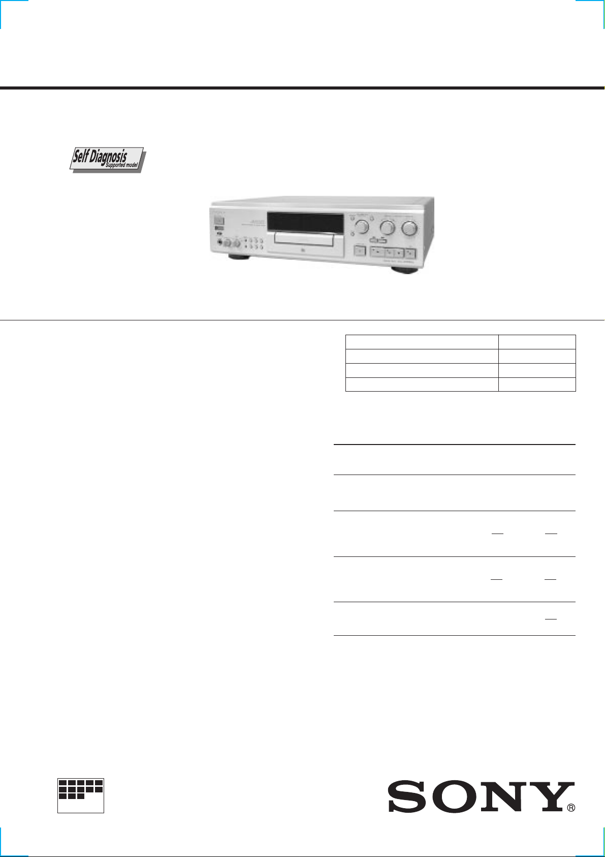
MDS-JA555ES
SERVICE MANUAL
Photo : GOLD
U.S. and foreign patents licensed from Dolby Laboratories
Licensing Corporation.
SPECIFICATIONS
US Model
Canadian Model
AEP Model
UK Model
Model Name Using Similar Mechanism MDS-JA20ES
MD Mechanism Type MDM-6A
Base Unit Type MBU-5C
Optical Pick-up Type KMS-260B/J1N
System MiniDisc digital audio system
Disc MiniDisc
Laser Semiconductor laser (λ=780 nm)
Emission duration : continuous
Laser output Less than 44.6 µW*
* This output is the value measured at a distance
of 200 mm from the objective lens surface on the
Optical Pick-up Block with 7 mm aperture.
Laser diode properties
Material: GaAlAs
Revolutions (CLV) 400 rpm to 900 rpm
Error correction ACIRC (Advanced Cross Interleave
Reed Solomon Code)
Sampling frequency 44.1 kHz
Coding ATRAC (Adaptive TRansform Acoustic Coding)
Modulation system EFM (Eight-to-Fourteen Modulation)
Number of channels 2 stereo channels
Frequency response 5 Hz to 20,000 Hz ± 0.3 dB
Signal-to-noise ratio Over 105 dB during playback
Wow and flutter Below measurable limit
Inputs
Jack Input Rated Minimum
type impedance input input
LINE Phono
(ANALOG) jacks 47 kΩ 500 mVrms 125 mVrms
IN
DIGITAL Square Optical wave
IN optical length
OPT1 connector 660 nm
jack
DIGITAL Square Optical wave
IN optical length
OPT2 connector 660 nm
jack
DIGITAL Phono 0.5 Vp-p
IN jack 75 Ω ±20%
COAXIAL
— Continued on next page —
MICROFILM
MINIDISC DECK
SAFETY CHECK-OUT
Output
Jack Rated Load
type output impedance
PHONES Stereo phone 28 mW 32 Ω
jacks
LINE(ANALOG) Phono 2 Vrms Over
OUT jacks (at 50 kΩ) 10 kΩ
DIGITAL OUT Square –18 dBm Optical
OPTICAL optical Wave length
connector 660 nm
jack
DIGITAL OUT Phono 0.5 Vp-p 75 Ω
COAXIAL jack (at 75 Ω)
General
Power requirements
Where purchased Power requirements
Continnental Europe and UK 220V – 230V AC, 50/60 Hz
U.S.A. and Canada 120 V AC, 60 Hz
Power consumption 24 W
Dimensions (approx.)(w/h/d) incl. projecting parts and controls
430 × 125.5 × 375.5 mm
(17 × 5 × 13 3/4 in.)
Mass (approx.) 15.3 kg (33 lbs 11 oz)
Supplied accessories
• Audio connecting cords (2)
• Remote commander (remote) RM-D34M (1)
• R6 (size-AA) batteries (2)
After correcting the original service problem, perform the
following safety checks before releasing the set to the customer:
Check the antenna terminals, metal trim, “metallized” knobs, screws,
and all other exposed metal parts for A C leakage. Check leakage as
described below.
LEAKAGE
The AC leakage from any exposed metal part to earth ground
and from all exposed metal parts to any exposed metal part having
a return to chassis, must not exceed 0.5 mA (500 microamperes).
Leakage current can be measured by any one of three methods.
1. A commercial leakage tester, such as the Simpson 229 or RCA
WT -540A. Follo w the manufacturers’ instructions to use these
instruments.
2. A battery-operated AC milliammeter. The Data Precision 245
digital multimeter is suitable for this job.
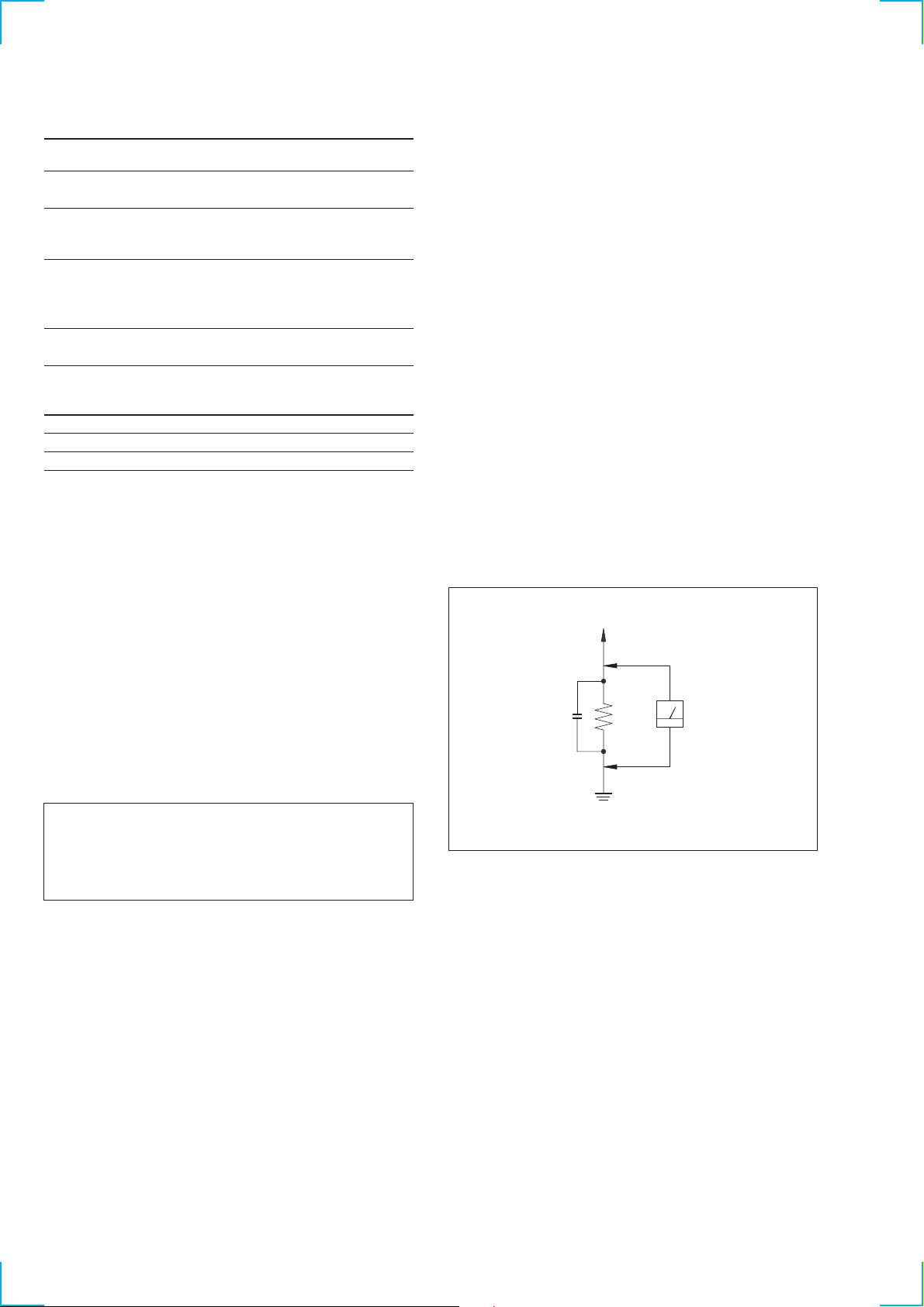
3. Measuring the voltage drop across a resistor by means of a
VOM or battery-operated AC v oltmeter . The “limit” indication
is 0.75 V, so analog meters must have an accurate low-volta ge
scale. The Simpson 250 and Sanwa SH-63Trd are e xamples of
a passive VOM that is suitable. Nearly all battery operated
digital multimeters that have a 2V AC range are suitable. (See
Fig. A)
T o Exposed Metal
Parts on Set
Design and specifications are subject to change without notice.
CAUTION
Danger of explosion if battery is incorrectly replaced.
Replace only with the same or equivalent type recommended by
the equipment manufacturer.
Discard used batteries according to manufacture’s instructions.
ADVARSEL!
Lithiumbatteri - Eksplosionsfare ved fejlagtig håndtering.
Udskiftning må kun ske med batteri af samme fabrikat og type.
Levér det brugte batteri tilbage til leverandøren.
ADVARSEL
Eksplosjonsfare ved feilakting skifte av batteri.
Benytt samme batteritype eller en tilsvarende type anbefalt av
apparatfabrikanten.
Brukte batterier katterier kasseres i henhold til fabrikantens
VARNIG
Explosionsfara vid felaktigt batteribyte.
Använd samma batterityp eller en likvärdig typ som rekommenderas
av apparattillverkaren.
Kassera använt batteri enligt gällande föreakrifter.
VAROITUS
Parist voi räjähtää, jos se on virheellisesti asennettu.
V aihda paristo ainoastaan laite valmistajan suosittelemaan tyyppiin.
Hävitä käytetty paristo valmistajan ohjeiden mukaisesti.
AC
µ
F
0.15
Fig. A. Using an AC voltmeter to check AC leakage.
SAFETY-RELATED COMPONENT WARNING!!
COMPONENTS IDENTIFIED BY MARK ! OR DO TTED LINE WITH
MARK ! ON THE SCHEMATIC DIAGRAMS AND IN THE PARTS
LIST ARE CRITICAL TO SAFE OPERATION. REPLACE THESE
COMPONENTS WITH SONY PARTS WHOSE PART NUMBERS
APPEAR AS SHOWN IN THIS MANUAL OR IN SUPPLEMENTS
PUBLISHED BY SONY.
ATTENTION AU COMPOSANT AYANT RAPPORT
LES COMPOSANTS IDENTIFÉS P AR UNE MARQUE ! SUR LES
DIAGRAMMES SCHÉMA TIQUES ET LA LISTE DES PIÈCES SONT
CRITIQUES POUR LA SÉCURITÉ DE FONCTIONNEMENT. NE
REMPLACER CES COMPOSANTS QUE PAR DES PIÈSES SONY
DONT LES NUMÉROS SONT DONNÉS DANS CE MANUEL OU
DANS LES SUPPÉMENTS PUBLIÉS PAR SONY.
1.5 k
Ω
Earth Ground
À LA SÉCURITÉ!
Voltmeter
(0.75 V)
2
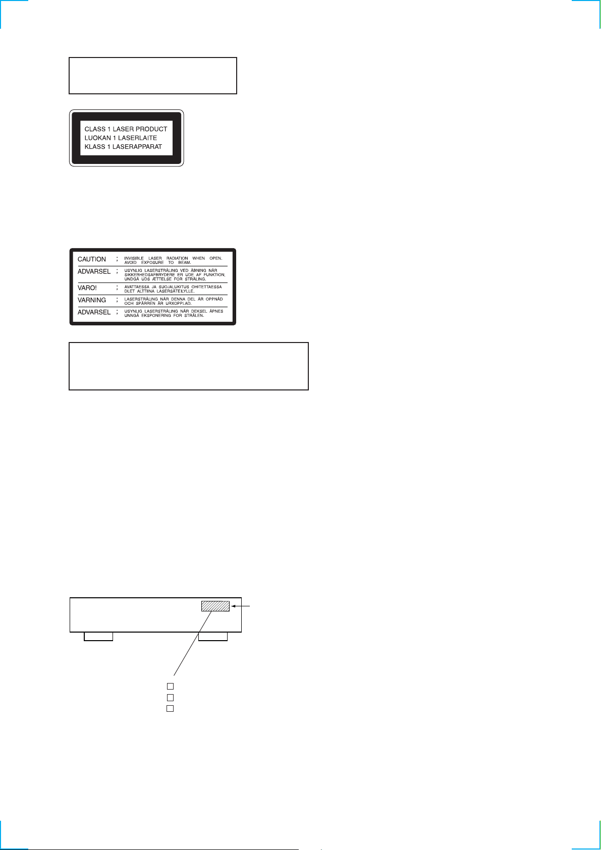
Laser component in this product is capable
of emitting radiation exceeding the limit for
Class 1.
This appliance is classified as a CLASS 1 LASER product. The
CLASS 1 LASER PRODUCT MARKING is located on the rear
exterior.
The following caution label is located inside the unit.
CAUTION
Use of controls or adjustments or performance of procedures
other than those specified herein may result in hazardous radiation
exposure.
Notes on chip component replacement
• Never reuse a disconnected chip component.
• Notice that the minus side of a tantalum capacitor may be
damaged by heat.
Flexible Circuit Board Repairing
• Keep the temperature of soldering iron around 270˚C
during repairing.
• Do not touch the soldering iron on the same conductor of the
circuit board (within 3 times).
• Be careful not to apply force on the conductor when soldering
or unsoldering.
MODEL IDENTIFICATION
— BACK PANEL —
Parts No.
4-220-300-1 : AEP, UK model
4-220-300-2 : US model
4-220-300-3 : Canadian model
TABLE OF CONTENTS
1. SERVICING NOTE·························································· 6
2. GENERAL ········································································ 12
3. DISASSEMBLY
3-1. Case ·················································································· 14
3-2. Loading Panel ··································································· 14
3-3. Front Panel Assembly······················································· 15
3-4. MD Mechanism Deck ······················································ 15
3-5. T ray Assembly·································································· 16
3-6. BU Holder Assembly························································ 17
3-7. Motor (Loading) Assembly (M10) ··································· 17
3-8. Base Unit (MBU-5C) ······················································· 18
3-9. BD Board·········································································· 18
3-10. Over Light Head (HP901) ················································ 19
3-11. Mini Disc Device (KMS-260B/JN) ·································· 19
4. TEST MODE ···································································· 20
5. ELECTRICAL ADJUSTMENTS ······························· 25
6. DIAGRAMS
6-1. Block Diagrams
BD Section ······································································· 34
MAIN Section ·································································· 35
Display/Power Supply Section ········································· 36
6-2. Circuit Boards Location ··················································· 37
6-3. Printed Wiring Board BD Section ································· 38
6-4. Schematic Diagram BD (2/1) Section··························· 39
6-5. Schematic Diagram BD (2/1) Section··························· 40
6-6. Schematic Diagram BD Switch Section························ 41
6-7. Printed Wiring Board BD Switch Section····················· 41
6-8. Printed Wiring Board AD Section ································· 42
6-9. Schematic Diagram AD (2/1) Section ··························· 43
6-10. Schematic Diagram AD (2/1) Section ··························· 44
6-11. Schematic Diagram DA (2/1) Section ··························· 45
6-12. Printed Wiring Board DA Section································· 48
6-13. Schematic Diagram DA (2/1) Section ··························· 47
6-14. Printed Wiring Board Digital Section ··························· 48
6-15. Schematic Diagram Digital Section ····························· 50
6-16. Printed Wiring Board AC Section ································· 51
6-17. Schematic Diagram Power Section ······························ 52
6-18. Printed Wiring Board Power Section ···························· 53
6-19. Printed Wiring Board Panel Section······························ 54
6-20. Schematic Diagram Panel Section ································ 55
6-21. IC Block Diagrams ··························································· 57
6-22. IC Pin Functions ······························································· 62
7. EXPLODED VIEWS
7-1. Upper Case Assembly ······················································ 71
7-2. Front Panel Assembly······················································· 72
7-3. Chassis Assembly····························································· 73
7-4. Mechanism Deck Assembly-1 (MDM-6A) ······················ 74
7-5. Mechanism Deck Assembly-2 (MDM-6A) ······················ 75
7-6. Base Unit (MBU-5C) ······················································· 76
8. ELECTRICAL PARTS LIST ······································· 77
3
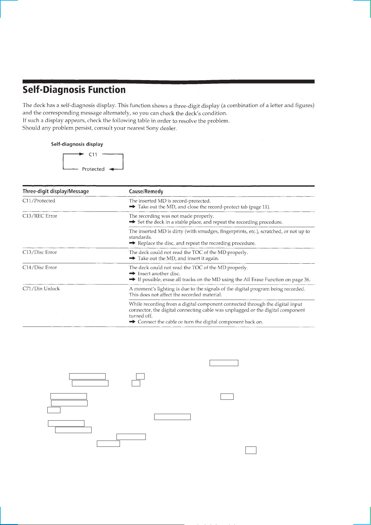
SELF-DIAGNOSIS FUNCTION
The self-diagnosis function consists of the error codes for users and those for service engineers. The error codes for users appear automatically when an error occurs. The error codes for service engineers can be accessed by entering the test mode during servicing and by viewing
the error history display. The error codes for users are shown belo w that are extracted from Operation Manual. For the error codes for service
engineers, refer to the subsequent paragraph “How to Operate the Self-diagnosis Function (Error History Display Mode)”.
How to Operate Self-diagnosis Function (Error History Display Mode)
Note: The self-diagnosis function is performed using the “error history display mode” using the test mode. The following procedure
describes only the minimum required operating procedure to enter the error history mode. Therefore be careful not to enter any other
modes by mistake. If you have entered any other modes by mistake, press the MENU/NO button and exit the mode.
1. While pressing the lAMSL knob and the x button at the same time, connect the A C po wer plug to the wall outlet, then remo ve
your hands from the lAMSL knob and x button at the same time. When the MDS-JA555ES enters the test mode, the message
“[Check]” appears and the STANDBY, PITCH CONTROL, and FILTER LEDs turn on.
2. Rotate the lAMSL knob until the message “Service” appears. Then press the YES button.
3. Rotate the lAMSL knob until the message “ERR DP MODE” appears.
4. Press the YES button to enter the error history mode and the message “total rec” appears.
5. Select the desired item to display or to execute using the lAMSL knob.
6. Press the lAMSL knob to display or execute the selected item.
7. Pressing the lAMSL knob again returns to the display of step 4.
8. To exit the error history mode, press the MENU/NO button. The message “ERR DP MODE” appears to exit the error history mode.
9. To exit the test mode, press the REPEAT button. The test mode display disappears and the PITCH CONTROL and FILTER LEDs are
turned off. The MDS-JA555ES enters the standby state exiting the test mode. While pressing the ?/1 button, turn on the main power .
The message “Initialize” flashes and the MDS-JA555ES is initialized.
4

[Displaying Contents of the Error History]
Display on screen
total rec
total play
retry err
total err
err history
er refresh
tm refresh
Contents of error history
Displays the recording time.
The display appears in “r h”. This is the accumulated time when the laser is in the “high power”
operation. This is about 1/4 of the actual recording time. The time is shown in the range of 0h to 65535h in
hexadecimal number.
Displays the playback time.
The display appears in “p h”. This is the accumulated time of actual playback in which pause time is
not counted. The time is shown in the range of 0h to 65535h in hexadecimal number.
Displays the accumulated count of record retry errors and playback retry errors.
The display appears in “r p ”. “r” indicates the record retry error count, and “p” indicates the playback
retry error count. The retry count is shown in the range of 00 to FF in hexadecimal number.
Displays the total error count.
The message “total ” appears. The count is shown in the range of 00 to FF in hexadecimal number.
Displays the error contents from the latest error to the last ten errors.
“0 E@@” appears. The history number is shown in . The smaller number means the newer history. (00 is
the newest error.) The error code is indicated by @@. Refer to the following table for the contents of the error
codes. The error histories can be switched by rotating the lAMSL knob.
This mode is used to delete the histories of “retry err”, “total err”, and “err history”.
Before returning the repaired product to the customer, perform this operation to delete the past error history. To
delete the history, press the lAMSL knob and press the YES button after “er refresh?” appears.
“Complete!” appears for a moment and returns to the ERR DP MODE.
When this mode is executed, be sure to check the following.
• The data have been deleted.
• Perform recording and playback. Check that the mechanism operates normally.
This mode is used to delete the histories of “total rec” and “total play”. These histories are used as reference
when replacing the optical pick-up.
When the optical pick-up is replaced, perform this operation to delete the histories. Press the lAMSL
knob. After “tm refresh?” appears, press the YES button to delete the histories. “Complete!” appears for a
moment and returns to the ERR DP MODE.
When this mode is executed, be sure to check the following.
• The data have been deleted.
• Perform recording and playback and check that the mechanism operates normally.
Error code table
Error code Error contents
E00 No errors
E01 Disc error Cannot read PTOC
(Disc is ejected)
E02 Disc error UTOC error
(Disc is not ejected)
E03 Loading error
E04 Cannot read the address (Out of servo)
Error code Error contents
E05 Out of FOK
E06 Focus does not lock (Out of servo)
E07 Record retry
E08 Record retry error
E09 Playback retry error
(Access error)
E0A Playback retry error (C2 error)
5
SECTION 1
SERVICING NOTE
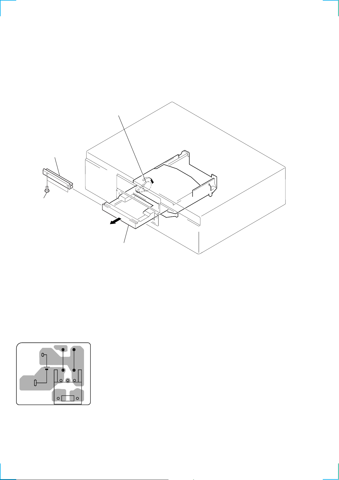
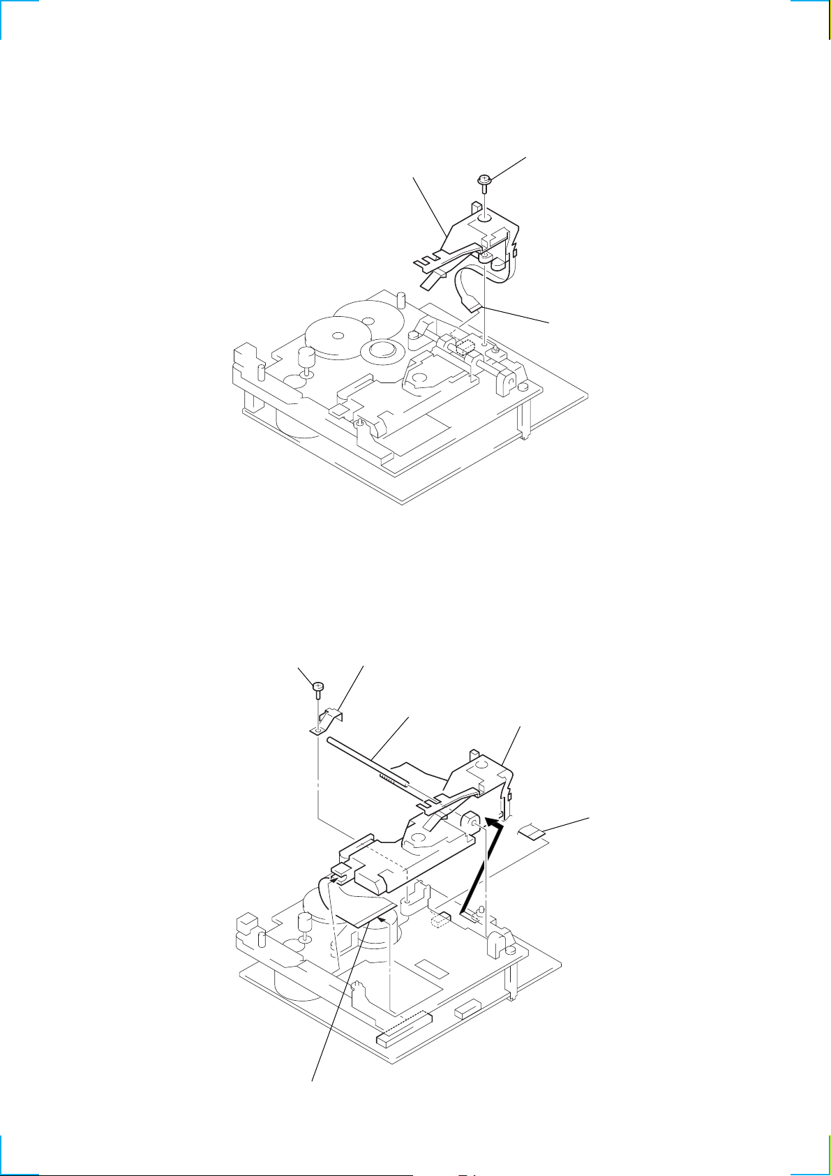
HOW TO OPEN THE DISC TRAY WHEN POWER SWITCH IS TURNED OFF, AND LASER POWER CHECK
1 Remove the 16 screws (BVTT3 x 8) from the bottom plate. (Refer to Section 3 “Disassembly” Loading panel.) (page 14)
2 Remove the bottom plate.
3 Rotate the pully gear in the direction of the arrow A and open the tray in the direction of the arrow B.
4 When checking the laser power, remove beforehand the loading panel by remo ving the two screws (M2.6) and sliding aside the loa ding
panel becouse the cable of the laser power meter can be pinched by the loading panel. (Refer to Section 3 “Disassembly” Loading
panel.) (page 14)
Pulley gear
Remove the Loading panel
A
Two screws
(M2.6)
B
Tray assembly
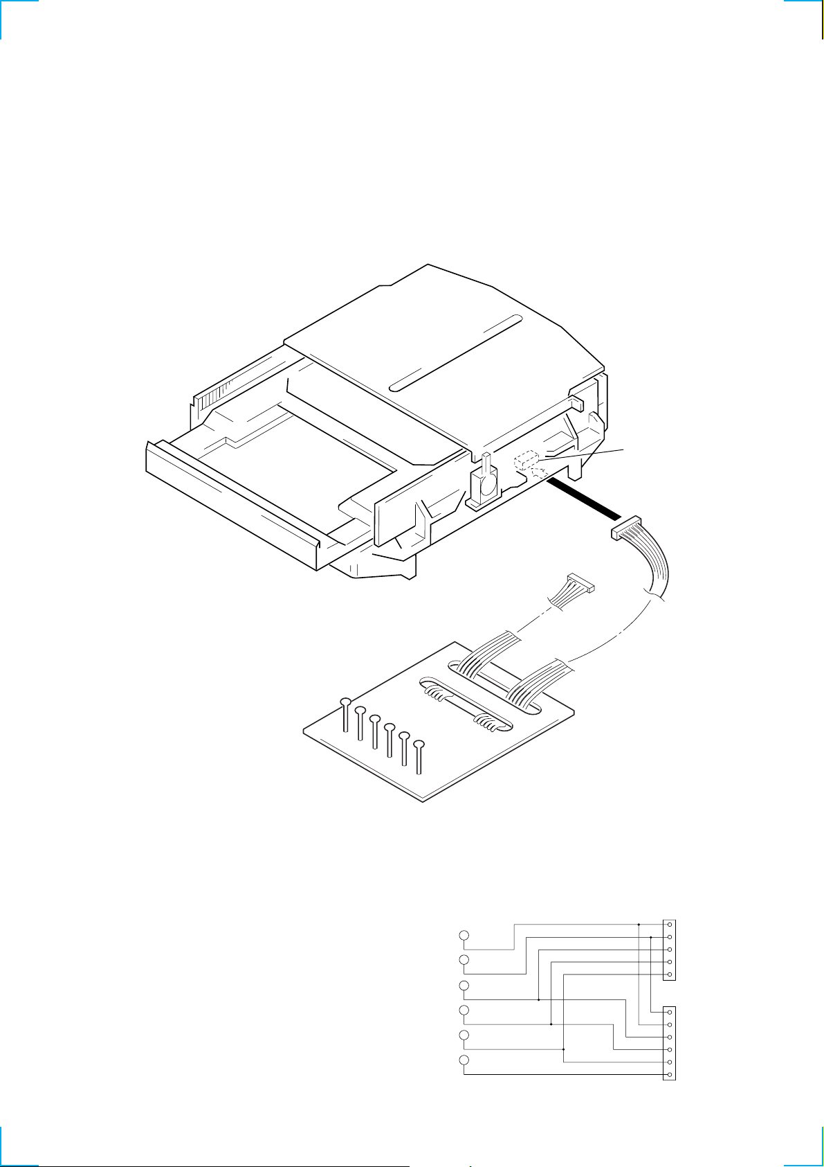
Forced Reset
Use this function when the MDS-JA555ES cannot be operated normally due to hung-up of the microprocessor.
It is recommended to use this function when you cannot exit the test mode or the retry-cause-display mode, or when the normal operation
cannot be performed after the MDS-JA555ES is disassembled once then re-assembled.
Procedure : Remove the AC power plug from the wall outlet. Short-circuit pin-1 and pin-3 of CN703 on the BT board with a pair of
tweezers or the like, to discharge the back-up battery.
[BT board] (Conductor side)
JW791
JW790
13
BT701
CN703
6
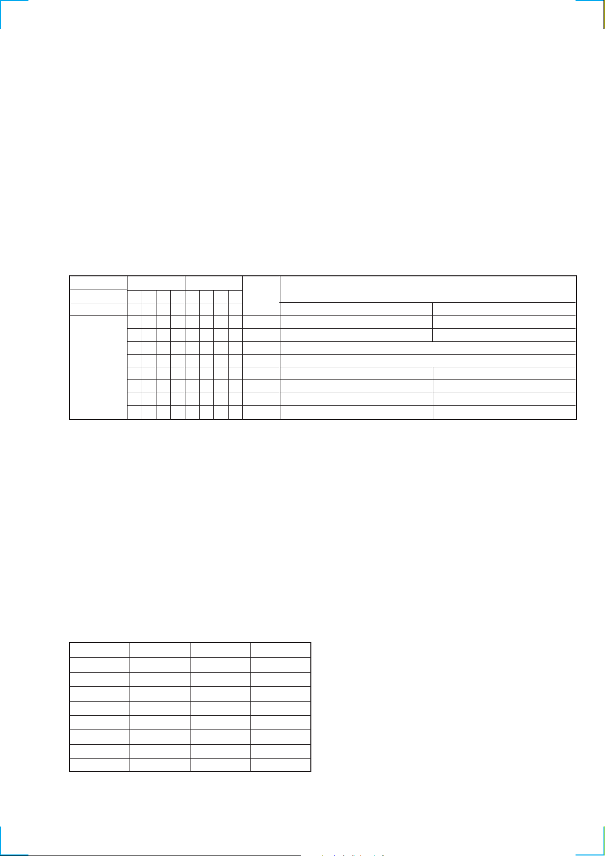
[BD Board Waveform Check Tool]
r
5
6
3
Use of the exclusive tool (J-2501-149-A) is convenient to check the waveforms on the BD board.
GND : Ground terminal
I+3V : For measuring IOP (Checking deterioration of the optical pickup laser)
IOP : For measuring IOP (Checking deterioration of the optical pickup laser)
TEO : TRK error signal (traverse adjustment)
VC : Reference level for when checking signals
RF : RF signal (jitter check)
CN110
6pin connecto
RF
VC
TEO
IOP
I+3V
GND
RF
VC
TEO
5pin connector
Schematic diagram of the connecting tools
1
RF
VC
TEO To MDMIOP
I-3V
5
IOP
I+3V
GND
1
VC
RF
To MDM-
TEO
To MDM-
IOP
I+3V
6
GND
7

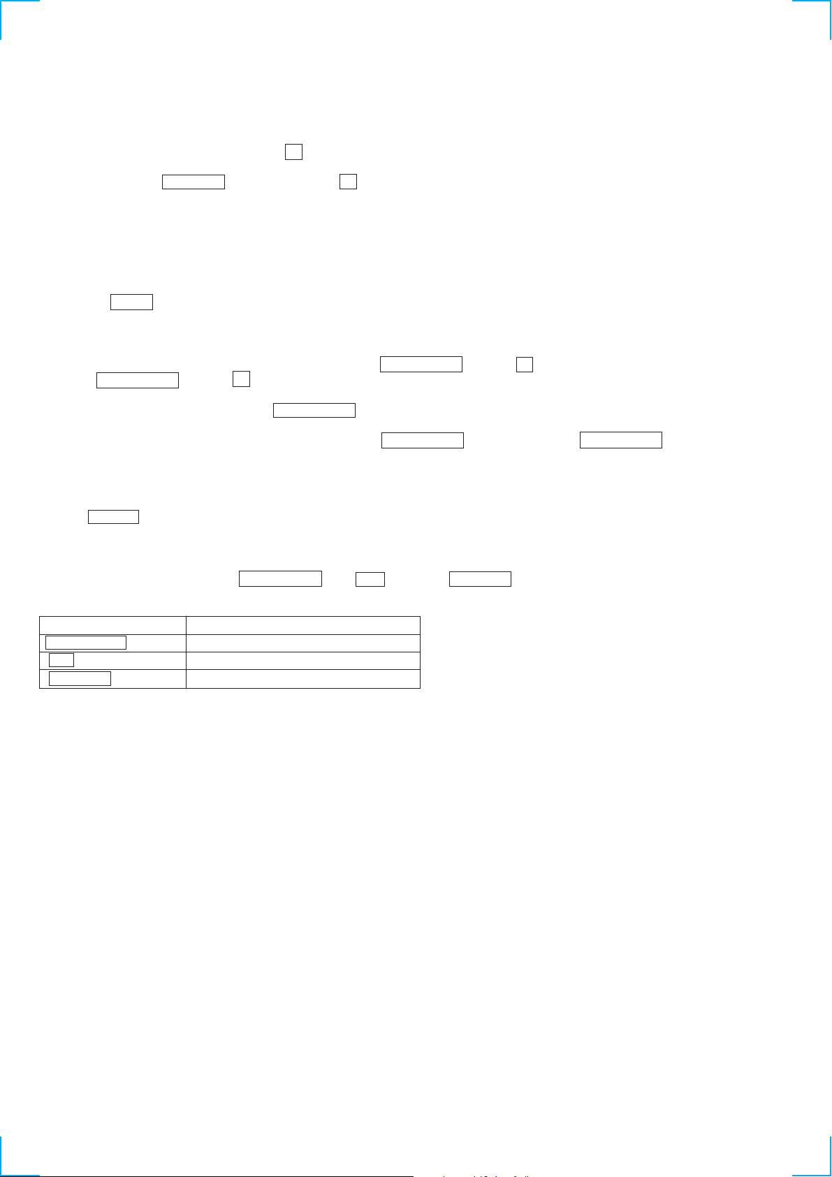
[How to Record and Display the IOP Data When Replacing the Optical Pick-up and Non-volatile Memory
(BD Board IC171)]
The IOP data that is indicated on the optical pick-up, can be saved in the non-volatile memory of the MDS-JA555ES. Saving the IOP data in
the memory eliminates the needs to look at the printed value on the label that is attached on the surface of optical pick-up, and enables to vie w
the IOP data on display. When the optical pick-up is replaced or when the non-volatile memory (IC171 on BD board) is replaced, save the
IOP value that is printed on the label on the surface of optical pick-up by the following procedure.
How to Record the IOP Data:
1. While pressing the lAMSL knob and the x button at the same time, connect the A C po wer plug to the wall outlet, then remo ve
your hands from the lAMSL knob and x button at the same time. When the MDS-JA555ES enters the test mode, the message
“[Check]” appears.
2. Rotate the lAMSL knob until the message “Service” appears. Then press the YES button.
3. Rotate the lAMSL knob until the message “lop Write” (C28) appears. Then press the YES button.
4. “Ref=@@@.@” (@ is arbitrary number) appears and the values that can be changed as desired flash.
5. Input the IOP value that is printed on the optical pick-up.
Selection of alphanumeric characters : Rotate the lAMSL knob.
Selection of digit : Press the lAMSL knob.
6. Press the YES button. Then display changes to “Measu= @@@.@” (@ is arbitrary number).
7. The v alue tha t is shown step 6, is the result adjustment and should not be saved. So leave the value of step 6 as it is, and press the YES
button.
8. The message “Complete!” appears for a moment, and the value is saved in the non-volatile memory. The message “Iop Write” appears.
9. Upon completion of data saving, press the REPEAT button.
How to Display the IOP Data:
1. While pressing the lAMSL knob and the x button at the same time, connect the A C po wer plug to the wall outlet, then remo ve
your hands from the lAMSL knob and x button at the same time. When the MDS-JA555ES enters the test mode, the message
“[Check]” appears.
2. Rotate the lAMSL knob until the message “Service” appears. Then press the YES button.
3. Rotate the lAMSL knob until the message “lop Write” (C28) appears. Then press the YES button.
4. The message “@@.@/##.#” appears. The contents that are saved in the non-volatile memory appear.
@@.@ : The IOP value that is printed on optical pick-up
##.# : The IOP value after adjustment
5. To exit the data display, press the lAMSL knob or the MENU/NO button to show the message “Iop Read”. Then press the
REPEAT button.
8

[Checks before Part Replacement and Adjustment]
Cause of faulty can be approximately located by performing the following checks before starting the repair work. Refer to Section “5.
Electrical Adjustment” the check procedure.
Laser power check
(Refer to section 5-6-2, page 27.)
Traverse check
(Refer to section 5-6-3, page 28.)
Focus bias check
(Refer to section 5-6-4, page 29.)
C PLAY check
(Refer to section 5-6-5, page 29.)
Self-recording/playback check
(REC/PLAY)
(Refer to section 5-6-6, page 29.)
Temperature compensation
offset check
(Refer to section 5-6-1, page 27.)
Judgment criterion(NG when the measurement
value is out of the specification value)
• 0.9 mW power
Specification value: 0.84 to 0.92 mW
• 7.0 mW power
Specification value: 6.8 to 7.2 mW
• Iop (when 7 mW)
The Iop value that is shown on the optical
pick-up: +/- 10 mA
• Traverse waveform
Specification value: Offset 10% or less
• Checking the error rate
Specification value: All points of a, b, and c
CI error 220 or less
AD error 2 or less
• Checking the error rate
Specification value:
a. When using the test disc (MDW-74/AU-1)
CI error 80 or less
AD error 2 or less
b. When using the check disc (TDYS-1)
CI error 50 or less
• Checking the error rate in C PLAY
Specification value:
CI error 80 or less
AD error 2 or less
• NG when “T=@@(##)(NG” appears
(@@ and ## are arbitrary numbers.)
Remedial measure in case of NG
• Cleaning the optical pick-up
• Readjustment
• Replacing the optical pick-up
• Replacing the optical pick-up
• Replacing the optical pick-up
• Replacing the optical pick-up
• Replacing the optical pick-up
In case of NG all the time:
• Replacing the overwrite head
• Check disconnection of the circuits around
the overwrite head
In case of intermittent NG:
• Check deformation of overwrite head
• Check mechanism around the sled
• Check disconnection of the circuits around
the D101 (BD board)
• Check signals around the IC101, IC121,
CN102 and CN103 (BD board)
Note: The judgment criterion is shown for the purpose of judging if the performance is acceptable or not. This is not the specification v alue for adjustment.
Use the specification value for adjustment when the MDS-JA555ES is going to be adjusted.
9

[Retry Cause Display Mode]
• In this test mode, the retry causes of the MDS-JA555ES during record and stop modes can be displayed on the fluorescent display tube.
This mode becomes the “track mode” during playback in which the track information is available.
This mode is useful for locating the defective area of the MDS-JA555ES.
• The contents to be displayed are as follows.
During record and stop modes: Retry cause, number of retries, and number of retry errors
During playback mode: Information such as disc types under playing back, position of playback and copyright.
Each information is displayed in hexadecimal number.
Procedure:
1. Load a recordable disc whose contents can be erased, into the MDS-JA555ES.
2. Press the MENU/NO b utton. After the message “Edit Menu” appears on the fluorescent display tube, rotate the lAMSL knob
until the message “All Erase ?” appears.
3. Press the YES button. (Alternately the lAMSL knob can also be pressed.)
4. The message “All Erase ??” appears on the fluorescent display tube. Then the numerals on the music calendar flash.
5. Press the YES button, then the message “Complete !!” appears. Press the x button immediately , and wait for about 15 seconds w hile
keeping pressing the button. (Alternately the lAMSL knob can be pressed instead of YES button.)
6. When the characters “TOC” have disappeared from the fluorescent display tube, remove your hands from the x button.
7. Press the zREC button to enter the record standby mode. Then press the X button to start recording.
8. When you want to enter the “Track mode”, press the N button to start playback.
9. To exit the test mode, press the ?/1 button. The message “TOC” flashes, the MDS-J A555ES enters the standby mode and e xits the test
mode.
Fig. 1 Reading the Test Mode Display (During record and stop modes)
RTs@@c##e**
Display on the fluorescent display tube
@@ : Cause of retry
## : Number of retries
** : Number of retry errors
Fig. 2 Reading the Test Mode Display (During playback)
@@ ####** $$
Display on the fluorescent display tube
@@ : Parts No. (Area name that is given on the TOC)
## : Cluster address (physical address on the disc)
** : Sector
$$ : Track mode (track information such as copyright information of each part, etc.)
How to read the retry cause display:
Lower Bits
Hexadecimal
01
shock
02
ader5
04
Address is not continuous
08
DIN unlock
10
FCS unlock
20
IVR rec error
40
CLV unlock
80
Access fault
Name of retry cause When 1
Hexadecimal
Bit
Binary number
Higher Bits
84218421
b7 b6 b5 b4 b3 b2 b1 b0
00000001
00000010
00000100
00001000
00010000
00100000
01000000
10000000
When track jump (shock) is detected
When ADER is counted five times or more continuously
When ADIP address is not continuos
Detects DIN unlock is detected
When focus is unlocked
When signal level of the ABCD signal exceeds the specified range
When CLV is unlocked
When access operation is not performed normally
10
Reading the Display:
Convert the hexadecimal display of each digit into binary display. If more than two causes, they will be added.
Example When 42 is displayed:
Higher bit: 4 = 0100 → b6
Lower bit: 2 = 0010 → b2
In this case, the retry cause is combined of “CLV unlock” and “ader5”.
Example When A2 is displayed:
Higher bit: A = 1010 → b7+b5
Lower bit: 2 = 0010 → b1
In this case, the retry cause is combined of “ACCESS default”, “IVRrec” and “ader5”.
The reading of the track mode display is as follows.
Higher Bits Lower Bits
Hexadecimal
Bit
Binary
Reading the Display:
Convert the hexadecimal display of each digit into binary display. The several causes are added and displayed.
Example When 84 is displayed:
Higher bit: 8 = 1000 → b7
Lower bit: 4 = 0100 → b2
This example shows that “Emphasis: OFF”, “Monaural”, “Original”, “Copyright exists” and “Writing is allo wed” because b2 and b7 are 1
while all other bits are 0.
Example When 07 is displayed:
Higher bit: 0 = 0000 → all 0
Lower bit: 7 = 0111 → b0+b1+b2
This example shows that “Emphasis: ON”, “Stereo”, “Original”, “Copyright exists” and “Writing is prohibited” because b0, b1 and b2 are
1 while all other bits are 0.
84218421
b7 b6 b5 b4 b3 b2 b1 b0
00000001
00000010
00000100
00001000
00010000
00100000
01000000
10000000
Hexadecimal
01
02
04
08
10
20
40
80
When 0 When 1
Emphasis OFF
Monaural
2-bit display, normally 01
01: Normal audio, Other: Invalid
Audio (normal)
Original
Copyright exists
Writing is prohibited
Contents
Emphasis OFF
Stereo
Invalid
Digital copy
No copyright
Writing is allowed
Hexadecimal → Binary Conversion Table
Hexadecimal Binary Hexadecimal Binary
0
1
2
3
4
5
6
7
0000
0001
0010
0011
0100
0101
0110
0111
8
9
A
B
C
D
E
F
1000
1001
1010
1011
1100
1101
1110
1111
11
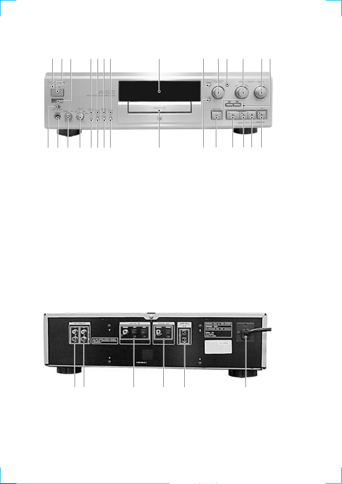
Front Panel
SECTION 2
GENERAL
1 2 3 4 5 6 7 8 9 0 qa qs qd qf
Rear Panel
1 SATNDBY indicator
2 1/u (POWER) button
3 Remote sensor
4 PITCH CONTROL button
5 SCROLL button
6 DISPLAY/CHAR button
7 REPEAT button
8 Display window
9 MENU/NO button
0 l AMS L knob
qa YES button
qs DIGITAL REC LEVEL knob
qd ANALOG REC LEVEL knob
qf 0 ) button
qg z REC button and indicator
wawswdwfwgwhwjwkwl
qh x (STOP) button
qj X (PAUSE) button and indicator
qk N (PLAY) button and indicator
ql A OPEN/CLOSE button
w; CLEAR button
wa Disc Tray
ws TIME button
wd PLAY MODE button
wf FADER button
wg FILTER button
wh INPUT button
wj PHONE LEVEL knob
wk PHONE jack
wl TIMER knob
qgqhqjqkqlw;
12
12 3 4 5 6
1 LINE (ANALOG) IN jack
2 LINE (ANALOG) OUT jack
3 DIGITAL IN (COAXIAL/OPT1/OPT2) jack
4 DIGITAL OUT
(COAXIAL/OPT1/OPT2) jack
5 CONTROL A1 II jack
6 Power Supply cord
This section is extracted
from instruction manual.
13

SECTION 3
)
n
DISASSEMBLY
Note : Follow the disassembly procedure in the numerical order given.
3-1. CASE
1
Two screws
(CASE 3 TP2)
A
3
Remove the upper case
in the direction of the arrow
1
Screw (CASE 3 TP2
A
.
3-2. LOADING PANEL
5
Loading panel
4
Two screws
(M2.6)
Tray assembly
B
2
Open the top cover
A
1
Two screws
(CASE 3 TP2)
3
in the direction of the arrow
and open the tray in the directio
of the arrow B.
2
Rotate the pulley gear
Bottom plate
A
,
14
1
Eight screws
(3
×
8)
1
Six screws
(3
×
8)
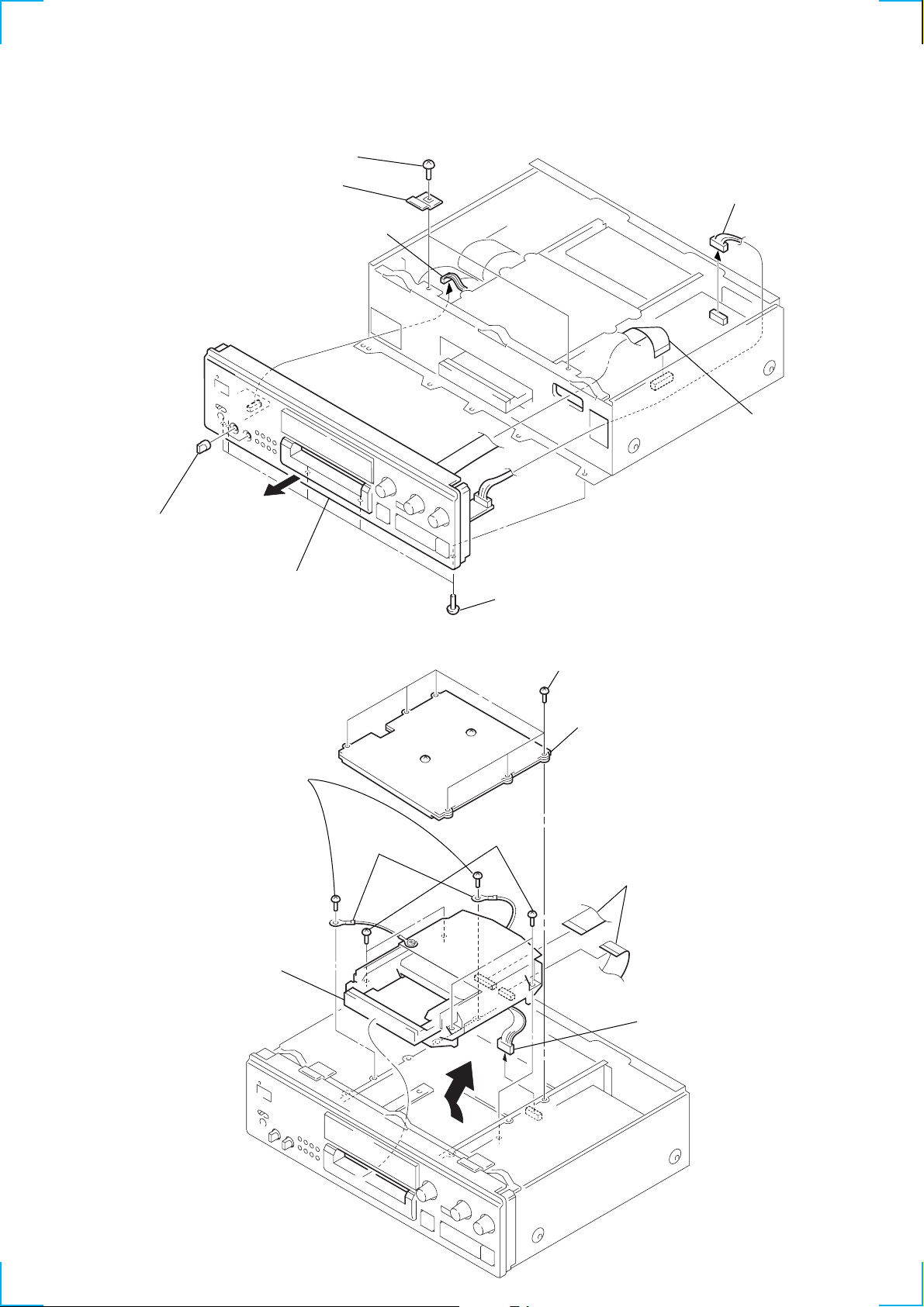
3-3. FRONT PANEL ASSEMBLY
e
6
Three screws
×
8 CU)
Bracket (F)
3
(CN651)
4
Two knobs (VOL)
(BV 3
7
Connector
2
Connector
(CN303)
1
Flat type wir
(CN800)
8
Front panel assembly
3-4. MD MECHANISM DECK
4
Two screws
(BVTT3 × 6)
8
Remove the MD
mechanism deck
in the direction of
the arrow A.
5
Two lug
terminals
5
Five screws
(3
6
Four screws
(BVTT 3 × 6)
×
8)
1
Six screws
(3 × 8)
2
Remove the cover (MDM-T) and
the fixing plate (MDM-T) together.
7
Two flat type wires
(CN102)
(CN102, 103)
(CN103)
3
Connector
(CN202)
A
15
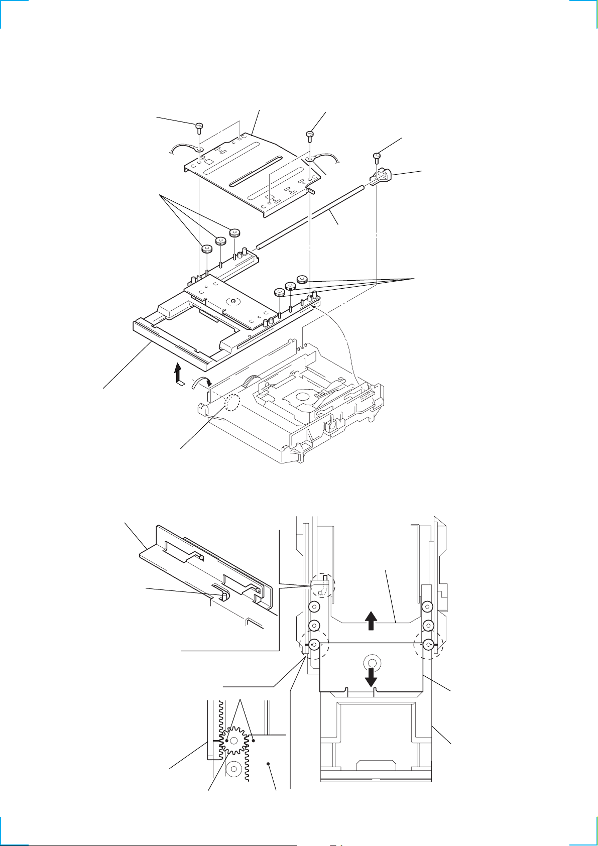
3-5. TRAY ASSEMBLY
)
y
2
Two screws
(BV2.6)
5
Three gears
(top)
4
Bracket (top)
2
Two screws
(BV2.6)
3
8
Lug
Shaft
6
Screw
(BV2.6)
7
5
Three gears (top)
Stopper (shaft B
9
Remove the tray asssembly
in the direction of the arrow
1
Rotate the pully gear in the direction
of the arrow
NOTE FOR INSTALLATION
Slider assembly
Pin
When the tray assembly is attached,
move the slider assembly in the direction
of the arrow B so that the pin is located
in the position as shown above.
Then attach the tray assembly.
B
B
A
and pull the tray assembly.
A
.
Slider assembly
B
When the gears (top) (two gears on the front)
are attached, pull the tray assembly out in the
direction of the arrow
and slider (D) assembly as shown.
A
and align the rack (L)
Rack (L)
16
Gear (top)
Mark
Slider (D) assembly
A
Slider (D) assembl
Tray assembly

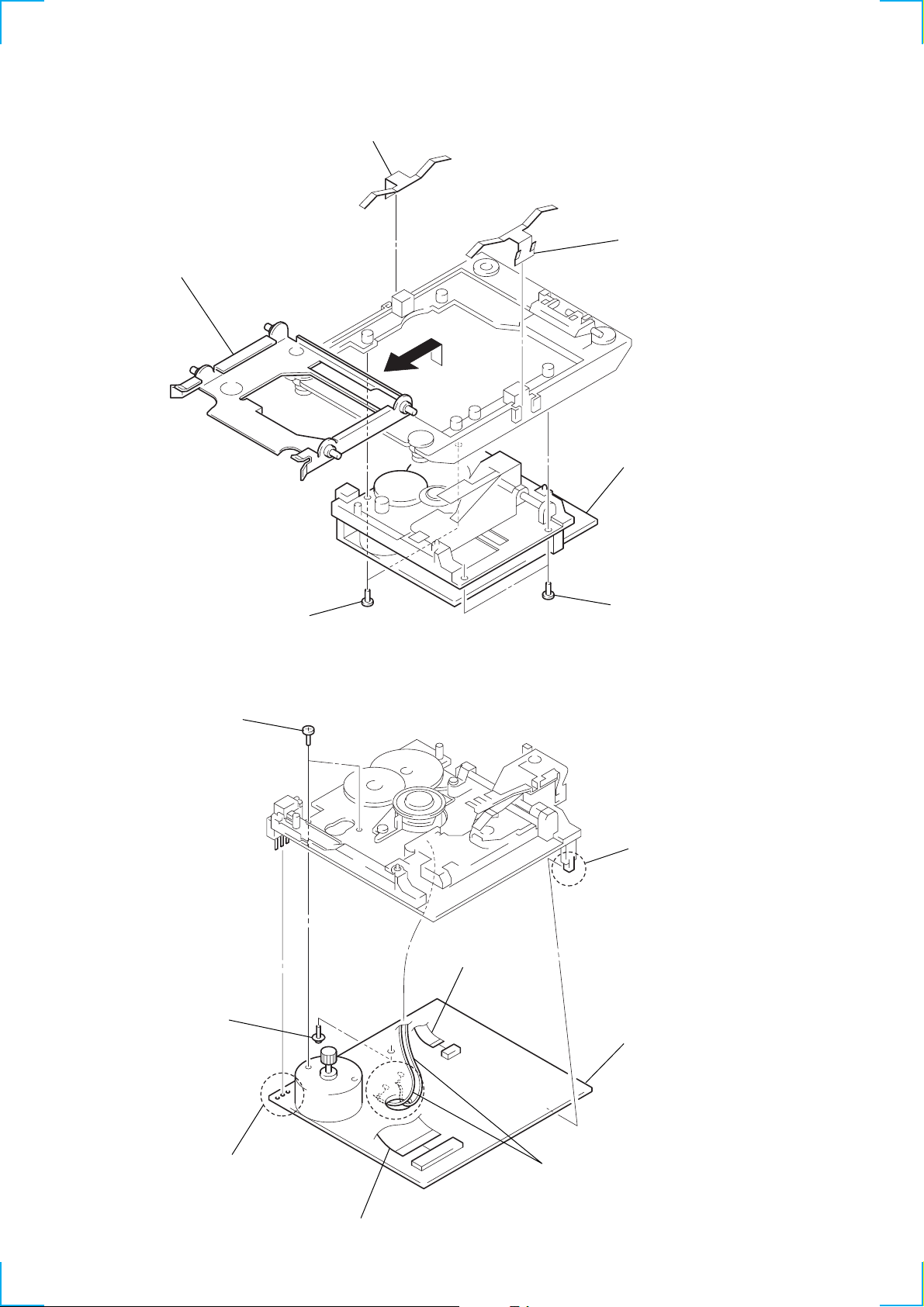
3-6. BU HOLDER ASSEMBLY
)
2
Two scews
(BV2.6)
3
Two collars
(damper)
4
Two compression
springs
2
Two scews
(BV2.6)
5
3
Two collars
(damper)
4
Two compression
springs
BU holder assembly
Fig. A
3-7. MOTOR (LOADING) ASSEMBLY (M10)
6
Motor (loading) assembly (M10)
1
Turn the pully gear to align
the slider with of the rib.
(Refer to Fig. A.)
3
Gear assembly
2
Two screws
(BV2.6)
Slider Rib
5
Two screws
×
3)
(B2
4
Belt (loading
1
Connector
(CN14)
17
3-8. BASE UNIT (MBU-5C)
)
3
Remove the holder assembly
in the direction of the arrow
A
1
Leaf spring (UDL)
2
Leaf spring (UDR
.
A
5
Base unit
3-9. BD BOARD
5
4
Two screws
(BV2.6)
Two precision screws
×
2.5)
(+P1.7
4
Tapping screw
(M1.7)
3
Flexible board
(CN104)
4
7
BD board
Two screws
(BV2.6)
6
Claw
18
2
Remove the soldering
from the push switch.
3
Flexible board
(CN101)
1
Remove the soldering of
the lead wires from
the spindle motor assembly.
3-10. OVER LIGHT HEAD (HR901)
d
3
Over light head
(HR901)
2
Screw
(P1.7
×
1
Flexible boar
(CN104)
6)
3-11. MINI DISC DEVICE (KMS-260B/J1N)
2
Screw +B
×
8)
(B2
3
Leaf spring (shaft)
4
Main shaft
5
Remove the mini disc device (KMS-260B/J1N)
in the direction of the arrow
1
Flexible board (CN104)
A
A
.
1
Flexible board (CN101)
19
SECTION 4
TEST MODE
4-1. Precaution on Using the Test Mode
• Be sure to insert and eject a disc after confirming that the disc in the MDS-JA555ES has come to complete stop because the loading
related movements of the mechanism are performed without any relationship with the test mode.
Disc does not stop rotating even through the A button is pressed while disc is rotating in the modes such as continuous playback and
continuous recording. Therefore, the disc is ejected while it is rotating.
Be sure to press the MENU/NO button, then press the A button after a disc has completely stopped of its rotation.
4-1-1. Modes in Which Recording Laser Emits the Light and the Button Operations
• Continuos recording mode (CREC MODE)
• Laser power check mode (LDPWR CHECK)
• Laser power adjustment mode (LDPWR ADJUST)
• Traverse (MO) check (EF MO CHECK)
• Traverse (MO) check (EF MO ADJUST)
• When the zREC button is pressed
4-2. How to Enter the Test Mode
There are two methods to enter the test mode as follows.
Method 1: Connect the power plug to the outlet while pressing the lAMSL knob and x button at the same time, and remove the
lAMSL knob and x button at the same time.
When the unit enters the test mode, “[Check]” appears. The four groups can be switched, ......↔ Check ↔Adjust ↔Service
↔Develop ↔..... , by rotating the lAMSL knob.
Method 2: Connect the power plug to the outlet while pressing the lAMSL knob, and remove the lAMSL knob.
When the unit enters the test mode, “TEMP CHECK” appears. When the test mode is entered using this method, the contents of
check group at method 1 can be performed.
4-3. Exiting the Test Mode
Press the REPEAT button. The display and LEDs of the pitch control and the filter are turned off. The MDS-JA555ES enters the standby
status and exits the test mode.
4-4. Basic Operation of the Test Mode
All operations are performed using the lAMSL knob, YES button, and MENU/NO button.
The functions of these button are as follows.
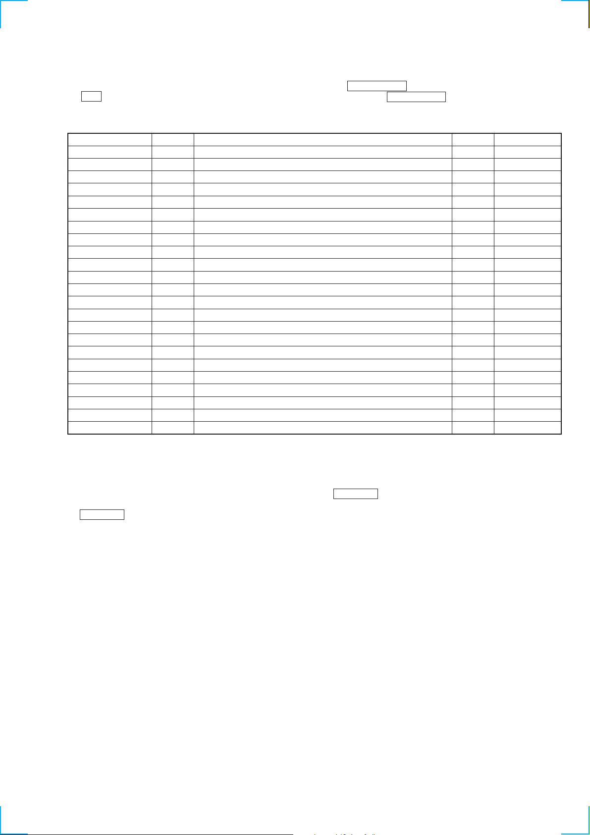
Function Contents
lAMSL knob Changes parameters and modes
YES button Proceeds onto the next step. Finalize input.
MENU/NO button Returns to previous step. Stops operations.
20
4-5. Selecting the Test Mode
There are 31 types of the test mode. The group can be switched by rotating the lAMSL knob. Select the group to be used and press
the YES button. After each group is entered, each mode can be switched by rotating the lAMSL .
For the selected contents, refer to the “Group” column in the list.
The group S can support all test modes for servicing. Be careful not to select other groups if not necessary.
Display
TEMP CHECK
LDPWR CHECK
EF MO CHECK
EF CD CHECK
FBIAS CHECK
ScurveCHECK
VERIFYMODE
DETRK CHECK
TEMP ADJUS
LDPWR ADJUS
EF MO ADJUS
EF CD ADJUS
FBIAS ADJUS
EEP MODE
ERR DP MODE
ADJ CLEAR
AG Set (MO)
AG Set (CD)
Iop Read
Iop Write
JA555 @@@@@@
CPLAY MODE
CREC MODE
• For detailed description of each adjustment mode, refer to Section 5 “Electrical Adjustments”.
For “ERR DP MODE” (C17), refer to the self-diagnosis function of page 2.
• If a different adjustment mode has been selected by mistake, press the MENU/NO button to exit from it.
• The items marked (×) in the mark are not used in servicing, therefore they are not detailed. . If select these modes accidentally, press the
MENU/NO button immediately to exit from it. If the items marked (!) are selected especially, the unit could be operated wrongly by
rewriting the contents of non-volatile memory. Be careful of it.
No.
C01
C02
C03
C04
C05
C06
C07
C08
C09
C10
C11
C12
C13
C14
C17
C24
C25
C26
C27
C28
C29
C30
C31
Contents
Temperature compensation offset check
Laser power check
Trav erse (MO) check
Traverse (CD) check
Focus bias check
S curve check
Non-volatile memory check
Detrack check
Temperature compensation offset adjustment
Laser power adjustment
Trav erse (MO) adjustment
Traverse (CD) adjustment
Focus bias adjustment
Non-volatile memory control
Error history display, clear
Initialization of non-volatile memory of adjustment value
Auto gain output level adjustment (MO)
Auto gain output level adjustment (CD)
IOP data display
IOP data writing
Version display of microprocessor
Continuous playback mode
Continuos recording mode
Mark
(×)
(×)
(×)
(×) (!)
(*) Group
C : Check A : Adjust
S : Service D : Develop
Group (*)
CS
CS
CS
CS
CS
C
C
C
AS
AS
AS
AS
AS
S
AS
AS
AS
CS
AS
CS
CASD
CASD
D
21

4-5-1. Operating the Continuos Playback Mode
1. Entering the continues playback mode
1)Load the disc into the unit. (recordable disc or disc for playback)
The disc is loaded by pushing the tray.
2)Rotate the lAMSL knob to display “CPLAY MODE” (C30).
3)Press the YES button to change the display to “CPLAY MID”.
4)When access completes, the display changes the display to “C = AD = ”.
Note : The value of the “ ” displayed on the screen indicates error rate and “ADER”.
2. Changing the parts to be played back
1)Press the YES button during continuos playback to change the display as shown and move the played back part.
"CPLAY MID" → "CPLAY OUT" → "CPLAY IN"
2)When access completes, the display changes to “C = AD = ”.
Note : The value of the “ ” displayed on the screen indicates error rate and “ADER”.
3. Ending the continuos playback mode
1) Press the MENU/NO button to change the display to “CPLAY MODE”.
2) Press the A button to eject the disc.
Note1 : The playback start addresses for IN, MID, and OUT are as follows.
IN : 40h cluster
MID : 300h cluster
OUT : 700h cluster
Note 2 : When the N button is pressed during the continuos playbac k in order to switch the tracking servo ON and OFF, the message
“SERVO ON” appears without displaying “CPLAY MODE” when the MENU/NO button is pressed to end the continuos
playback mode.
Also when the servo is turned off, the serv o is turned on automatically, the message “SERV O ON” appears and then the mode
ends afterward.
To change the display “SERVO ON” to the normal “mode” display, press the x button.
22

4-5-2. Operating the Continuos Recording Mode (Use this mode for self record/playback check only)
1. Entering the continuos recording mode
1)Load the recordable disc to the unit.
The disc is loaded by pushing the tray.
2)Rotate the lAMSL knob to display “CREC MODE” (C31).
3)Press the YES button to change the display to “CREC MID”.
4)When access completes, the display changes the display to “CREC( ” and illuminates.
Note : The value of the “ ” displayed on the screen indicates the address of the recorded position.
2. Changing the parts to be recorded
1) Press the YES button during continuos playback to change the display as shown and move the played back part. disappear s
during moving.
"CREC MID" → "CREC OUT" → "CREC IN"
REC
REC
2)When access completes, the display changes to “CREC( ” and disappears.
Note : The value of the “ ” displayed on the screen indicates the address of the recorded position.
3. Ending the continuos recording mode
1) Press the MENU/NO button. The display changes to “CREC MODE” and disappears.
2) To eject the disc, press the A button.
Note 1: The playback start addresses for IN, MID, and OUT are as follows.
N : 40h cluster
MID : 300h cluster
OUT : 700h cluster
Note 2: The MENU/NO button can be used to stop recording anytime.
Note 3: Do not perform continuos recording for long periods of time above 5 minutes.
Note 4: During continuos recording, be careful not to apply vibration.
4-5-3. No-Volatile Memory Mode (EEP MODE)
This mode reads and writes the contents of the non-volatile memory.
It is not used in servicing. If selecting this mode accidentally, press the MENU/NO button immediately to exit it.
REC
REC
4-6. Functions of Other Buttons
Function name Main contents
N Sets continuos playback when pressed in the STOP state. When pressed during continuos playback, the tracking
servo turns ON/OFF. *Note
x Stops continuos playback and continuous recording
M The sled moves to the outer circumference only when this is pressed
m The sled moves to the inner circumstance only when this is pressed
SCROLL Switches between the pit and groove modes when pressed
PLAY MODE Switches the spindle servo mode (CLV S ↔ CLV A)
DISPLAY/CHAR Switches the display when pressed
A/OPEN/CLOSE Removes the disc
REPEAT Exits test mode
Note : If the continuos playback mode ends with the tracking servo OFF, the tracking servo is automatically turned on.
When the message “SERVO ON” appears at the end, press the x button to returns to the normal “mode” display.
23
4-7. Test Mode Displays
Each time the DISPLAY/CHAR button is pressed, the display changes in the following order.
1. MODE display
Displays “TEMP CHECK”, “CPLAY MODE”, etc.
2. Error rate display
Error rates are displayed as follows.
C = AD =
C = Indicates CI error
AD = Indicates ADER
3. Address display
Addresses are displayed as follows.
(MO: recordable disc, CD: disc for playback only)
Every pressing of the SCROLL button toggles between the groove display
and the pit display
h = s = (MO pit and CD)
h = a = (MO groove)
h = : Indicates header address
s = : Indicates SUBQ address
a = : Indicates ADIP address
Note: The display “-” appears when the servo is not locked.
4. Auto gain display (not used in servicing)
The auto gain display is shown as follows.
AG= / [
5. Detrack check display (not used in servicing)
The detrack check display is shown as follows.
ADR=
6. IVR display (not used in servicing)
The IVR display is shown as follows.
[ ] [ ] [
Auto gain display (not used in servicing)
Detrack check display (not used in servicing)
IVR display (not used in servicing)
MODE display
↓
Error rate display
↓
Address display
↓
↓
↓
↓
Meaning of Other Displays
Display
H
X
REC
-SYNC
A. SPACE
OVER
B
A-
TRACK
DISC
SLEEP
CLOCK
MODE display Off
During continuos playback (CLV: ON) STOP (CLV:OFF)
Tracking servo OFF Tracking servo ON
Recording mode OFF Recording mode OFF
CLV low speed mode CLV normal mode
ABCD adjustment completed
Tracking offset cancel ON Tracking offset cancel OFF
Tracking auto gain OK
Focus auto gain OK
Pit Groove
High reflection Low reflection
CLV-S CLV-A
CLV LOCK CLV UNLOCK
Contents
24

SECTION 5
ELECTRICAL ADJUSTMENTS
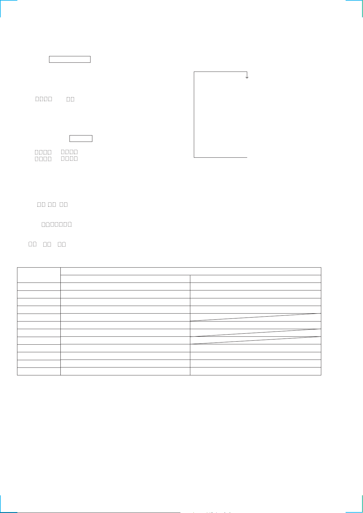
5-1. On Part Replacement and Adjustment
• Perform the checks and adjustments of the MDM and MBU blocks following the procedure below .
The procedure is changed depending on the replaced part.
• Abbreviation
OP : Optical pick-up
•
Temperature compensation
offset check
•
Laser power check
•
Traverse check
•
Focus bias check
•
C PLAY check
•
Self record/playback check
OWH : Overwrite head
OK
NG
Part Replacement and repairing
OWH is replaced ?
NO
Either OP, IC171, IC101, or
IC121 is replaced ?
YES
Initial setting of adjustment value
OP or IC171 is replaced ?
YES
Recording the IOP information
(IOP value that is recorded in OP)
The error occurs by other cause.
Perform the mechanism check of
the sled and spindle system, etc.
YES
NO
NO
Either IC171 or D101 is replaced ?
YES
Temperature compensation offset adjustment
• T ra verse adjustment
• Focus bias adjustment
• Error rate adjustment
• Auto gain adjustment
NO
25

5-2. Precautions for Checking Laser Diode
Emission
T o check the emission of the laser diode during adjustments, ne v er
view directly from the top as this may lose your eye-sight.
5-3. Precautions for Use of Optical Pick-up
(KMS-260B)
As the laser diode in the optical pick-up is easily damaged by static
electricity, solder the laser tap on the flexible board of the optical
pick-up when using it.
Before disconnecting the connector, disorder the laser tap. Be careful
not to remove the solder before connecting the connector . Also take
adequate measures to prevent damage by static electricity. Handle
the flexible board with care as it breaks easily.
Pick-up
Laser tap
Optical pick-up flexible board
Flexible board
5-4. Precautions for Adjustments
1) When replacing the following parts, perform the
adjustments and checks with !! in the order shown in the
following table.
2) Set the test mode when performing the adjustments.
After completing the adjustments, exit the test mode.
Perform the adjustments and checks in “Group S” of the test
mode.
3) Perform the necessary adjustments only in the order given.
4) Use the following tools and measuring devices.
• Check disc (MD) TDYS-1 (Parts No.: 4-963-646-01)
• Test disc (MDW-74/AU-1) (Parts No.: 8-892-341-41)
• Laser power meter LPM-8001 (Parts No.: J-2501-046-A)
Or
• MD laser power meter 8010S (Parts No.: J-2501-145-A)
(Note)
• Oscilloscope (Measure after perform the CAL of the probe.)
• Digital voltmeter
• Thermometer
• T ool for checking wav eform of BD board (Parts No.: J-2501-
149-A)
5) When observing several signals on the oscilloscope, etc., make
sure that VC and ground do not connect inside the oscilloscope.
(VC and ground will become short-circuited.)
6 When checking the waveform, the check can be performed
without soldering by using the tool for checking waveform of
BD board.
(Refer to the Service note (page 6).)
7) Use the tool disc that is free from finger print and dust as they
can affect result of adjustment.
Note: Laser power meter
When the laser power check and adjustment of the electrical
adjustment are performed, using the new MD laser power meter
8010S (J-2501-145-A) instead of the former laser power meter is
recommended.
The procedure of installing the laser meter sensor to the objective
lens of pickup is greatly simplified.
1. Initial setting of
adjustment value
2. Recording IOP
information
(the value that is
written in pick-up)
3. Temperature
compensation offset
adjustment
4. Laser power
adjustment
5. Traverse adjustment
6.
Focus bias adjustment
7.
Error rate adjustment
8. Auto gain output
level adjustment
Optical
pick-up
a
a
×
a
a
a
a
a
IC171
a
a
a
a
a
a
a
a
BD board
IC101,
D101
×
×
a
×
×
×
×
×
IC121
a
×
×
a
a
a
a
a
IC192
×
×
×
a
×
×
×
×
26

5-5. Creating Continuos Recorded Disc
KMS
260B
24391
H0528
(For the checking procedure of
this value, refer to Section 5-8
“Recording and displaying IOP information”.)
IOP = 52.8 mA in this case
IOP (mA) = digital bolt meter reading (mV)/1 (W)
(Optical pick-up label)
• This disc is used in focus bias adjustment and error rate check.
The following describes how to create a continuos recording disc.
1. Load a disc (blank disc) commercially available.
the disc is loaded by pushing the tray.
2. Rotate the lAMSL knob and display “CREC MODE”
(C31).
3. Press the YES button to display “CMEC MID”.
“CREC (0300)” is displayed for a moment and recording starts.
4. Complete recording within 5 minutes.
5. Press the MENU/NO button to stop recording.
6. Press the A button to eject the disc.
The above has been how to create a continuos recording data for
the focus bias adjustment and error rate check.
Note:
• Be careful not to apply vibration during continuos recording.
5-6. Check before Repairing
This check aims at locating the approximate position of cause of
trouble before starting to replace parts using specifications.
For detailed information, refer to [Checks before Part Replacement
and Adjustment] of Service note (page 9).
5-6-1. Temperature Compensation Offset Check
Before adjustment, set the internal temperature and the ambient
temperature are between 22 and 28 °C.
Checking procedure:
1. Rotate the lAMSL knob to display “TEMP CHECK”
(C01).
2. Press the YES button.
3. It is OK when “T=@@(##)[OK” appears. It is NG when
“T=@@(##)[NG” appears. (@@ is the current value. ## is the
value that is written in the non-volatile memory.)
5-6-2. Laser Power Check
Before check:
• Refer to Section 1 “Service note” How to open the disc tray when
power switch is turned off, and laser power check.
• Check the IOP value of optical pick-up. (Refer to Section 5-8
“Recording and displaying IOP information”.)
Connection:
Laser power meter
Optical pick-up
objective lens
Digital voltmeter
BD board
CN110 5-pin (I+3V)
CN110 4-pin (IOP)
Checking procedure:
1. Insert the laser power meter from the disc inlet and set it on the
objective lens of the optical pick-up. (When it cannot be set
properly, press the m button and M button to move the
optical pick-up.)
Connect the digital voltmeter to CN110 5-pin (I+3V) and the
CN110 4-pin (IOP).
2. Rotate the lAMSL knob to display “LDPWR CHECK”
(C02).
3. Press the YES button once to display “LD 0.9mW $ ”.
Confirm that the reading of the laser power meter is 0.84 to
0.92 mW.
4. Press th
e YES button once again to display “LD 7.0mW $ ”.
Confirm that the readings of the laser power meter and digital
bolt meter satisfy the specified value.
Specification:
Laser power meter reading: 7.0 +/- 0.2 mW
Digital bolt meter reading: Optical pick-up displayed value +/- 10 %
5. Press the MENU/NO button to display “LDPWR CHECK”
and stop laser emission.
(The MENU/NO button is effective at all times to stop the
laser emission.)
Note 1 : After step 4, the display of “LD 0.7mW$ ” “LD
6.2mW$ ”, “LD WPcorrection $ ” is switched
every time when pressing the YES button. Operation
is not necessary for these displays.
27
 Loading...