

Page 1
LCD Monitor
2-659-026-13 (1)
Instructions for Use
LMD-1420MD
© 2005 Sony Corporation
Page 2

Owner’s Record
The model and serial numbers are located at the rear.
Record these numbers in the spaces provided below.
Refer to these numbers whenever you call upon your
Sony dealer regarding this product.
Model No. ____________________
Serial No. ____________________
WARNING
To reduce the risk of fire or electric shock, do not
expose this apparatus to rain or moisture.
To avoid electrical shock, do not open the cabinet.
Refer servicing to qualified personnel only.
In the event of a malfunction or when maintenance is
necessary, consult an authorized Sony dealer.
This unit contains substances which can pollute the
environment if disposed carelessly. Please contact our
nearest representative office or your local environmental
office in case of disposal of this unit.
WARNING
THIS APPARATUS MUST BE EARTHED.
FOR CUSTOMERS IN EUROPE
This equipment has been found to comply with limits for
a Class B device pursuant to EN60601-1-2. However, if
this equipment does cause harmful interference to other
devices, which can be determined by turning this
equipment off and on, the user is encouraged to try to
correct the interference by one or more of the following
measures:
• Increase the separation between the equipment and
other devices.
• Connect the equipment into an outlet on a circuit
different from that to which other devices are
connected.
• Consult the dealer or an experienced radio/TV
technician for help.
For the customers in Canada
This unit has been certified according to Standard CSA
C22.2 NO.601.1.
FOR THE CUSTOMERS IN THE USA
This equipment has been tested and found to comply
with the limits for a Class A digital device, pursuant to
Part 15 of the FCC Rules. These limits are designed to
provide reasonable protection against harmful
interference when the equipment is operated in a
commercial environment. This equipment generates,
uses, and can radiate radio frequency energy and, if not
installed and used in accordance with the instruction
manual, may cause harmful interference to radio
communications. Operation of this equipment in a
residential area is likely to cause harmful interference in
which case the user will be required to correct the
interference at his own expense.
You are cautioned that any changes or modifications not
expressly approved in this manual could void your
authority to operate this equipment.
All interface cables used to connect peripherals must be
shielded in order to comply with the limits for a digital
device pursuant to Subpart B of Part 15 of FCC Rules.
This product contains mercury. Disposal of this product
may be regulated if sold in the United States. For
disposal or recycling information, please contact your
local authorities or the Electronics Industries Alliance
(http://www.eiae.org).
2
Page 3

Important safeguards/notices for use in the
medical environments
1. All the equipment connected to this unit shall be
certified according to Standard IEC60601-1,
IEC60950-1, IEC60065 or other IEC/ISO Standards
applicable to the equipment.
2. When this unit is used together with other equipment
in the patient area*, the equipment shall be either
powered by an isolation transformer or connected via
an additional protective earth terminal to system
ground unless it is certified according to Standard
IEC60601-1 and IEC60601-1-1.
* Patient Area
R1.5m
WARNING on power connection for
medical use
Please use the following power supply cord.
With connectors (plug or female) and cord types other
than those indicated in this table, use the power supply
cord that is approved for use in your area.
United States Canada
Plug Type HOSPITAL GRADE* HOSPITAL GRADE*
Female end E62405, E35708 LR53182, LL022442,
Cord type E159216, E35496
Minimum cord set
rating
Safety approval UL Listed CSA
*Note: Grounding reliability can only be achieved when the equipment is connected to an equivalent receptacle marked ‘Hospital Only’
or ‘Hospital Grade’.
Min.Type SJT
Min.18 AWG
10A/125V 10A/125V
Symbols on the unit
LL088408
LL112007-1, LL20262,
LL32121, LL84494
Min.Type SJT
Min.18AWG
3. The leakage current could increase when connected
to other equipment.
4. The operator should take precautions to avoid
touching the rear panel input and output circuitry and
the patient at the same time.
5. Model LMD-1420MD is a monitor intended for use
in a medical environment to display pictures from
cameras or other systems. These models are
nonpatient care equipment with respect to the
requirement of leakage current.
Caution
When you dispose of the unit or accessories, you must
obey the law in the relative area or country and the
regulation in the relative hospital.
WARNING on power connection
Use a proper power cord for your local power supply.
1. Use the approved Power Cord (3-core mains lead) /
Appliance Connector / Plug with earthing-contacts
that conforms to the safety regulations of each
country if applicable.
2. Use the Power Cord (3-core main lead) / Appliance
Connector / Plug conforming to the proper ratings
(Voltage, Ampere).
If you have questions on the use of the above Power
Cord / Appliance Connector / Plug, please consult a
qualified service personnel.
Symbol Location This symbol indicates
Front Main power switch.
Rear The equipotential
Rear Functional earth terminal
Front Key inhibit
-
terminal which brings the
various parts of a system
to the same potential.
The setting are locked so
that they cannot be
changed.
3
Page 4

Table of Contents
Precaution .............................................................. 5
On Safety ............................................................ 5
On Installation .................................................... 5
Handling the LCD Screen .................................. 5
About the Fluorescent Tube ............................... 5
On Cleaning ....................................................... 5
On Repacking ..................................................... 6
On Mounting on a Rack ..................................... 6
On Fan Error ...................................................... 6
On the Delay of the Video Signal ...................... 6
Features .................................................................. 6
Location and Function of Parts and Controls .... 8
Front Panel ......................................................... 8
Input Signals and Adjustable/Setting Items ....... 9
Rear Panel ........................................................ 10
Installing to the Rack .......................................... 11
Connecting the AC Power Cord ......................... 12
Attaching the Input Adaptor .............................. 12
Selecting the Default Settings ............................. 13
Selecting the Menu Language ............................ 14
Using the Menu .................................................... 15
Adjustment Using the Menus ............................. 16
Items ................................................................. 16
Adjusting and Changing the Settings ............... 17
STATUS menu............................................. 17
COLOR TEMP/BAL menu ......................... 17
USER CONTROL menu.............................. 17
USER CONFIG menu.................................. 18
REMOTE PARALLEL menu...................... 19
KEY INHIBIT menu.................................... 19
Troubleshooting ................................................... 19
Specifications ....................................................... 20
Dimensions ........................................................... 23
4
Page 5

Precaution
On Safety
• If a still picture is displayed for a long time, a residual
image may appear. The residual image will eventually
disappear.
• The screen and the cabinet become warm during
operation. This is not a malfunction.
• Operate the unit only with a power source as specified
in the “Specifications” section.
• A nameplate indicating operating voltage, power
consumption, etc., is located on the rear panel.
• Should any solid object or liquid fall into the cabinet,
unplug the unit and have it checked by qualified
personnel before operating it any further.
• Do not drop or place heavy objects on the power cord.
If the power cord is damaged, turn off the power
immediately. It is dangerous to use the unit with a
damaged power cord.
• Unplug the unit from the wall outlet if it is not to be
used for several days or more.
• Disconnect the power cord from the AC outlet by
grasping the plug, not by pulling the cord.
• The socket-outlet shall be installed near the equipment
and shall be easily accessible.
On Installation
• Allow adequate air circulation to prevent internal heat
build-up.
Do not place the unit on surfaces (rugs, blankets, etc.)
or near materials (curtains, draperies) that may block
the ventilation holes.
• Do not install the unit in a location near heat sources
such as radiators or air ducts, or in a place subject to
direct sunlight, excessive dust, mechanical vibration
or shock.
Handling the LCD Screen
• Bright or dark points of lights (red, blue or green) may
appear on the LCD screen. This is not a malfunction.
The LCD screen is made with high-precision
technology with more than 99.99 % of the picture
elements intact. However, some picture elements may
not appear intermittently.
• Do not leave the LCD screen facing the sun as it can
damage the LCD screen. Take care when you place
the unit by a window.
• Do not push or scratch the LCD monitor’s screen. Do
not place a heavy object on the LCD monitor’s screen.
This may cause the screen to lose uniformity.
• If the unit is used in a cold place, horizontal lines or a
residual image may appear on the screen. This is not
a malfunction. When the monitor becomes warm, the
screen returns to normal.
About the Fluorescent Tube
A specially designed fluorescent tube is installed as the
lighting apparatus for this unit. If the LCD screen
becomes dark, unstable or does not turn on, consult your
Sony dealer.
On Cleaning
Before cleaning
Be sure to disconnect the AC power cord from the AC
outlet.
On cleaning the monitor
A material that withstands sterilization is used for the
front protection plate of the medical use LCD monitor.
The protection plate surface is especially treated to
reduce reflection of light. When solvents such as
benzene or thinner, or acid, alkaline or abrasive
detergent, or chemical cleaning cloth are used for the
protection plate surface/monitor surface, the
performance of the monitor may be impaired or the
finish of the surface may be damaged. Take care with
respect to the following:
• Clean the protection plate surface/monitor surface
with a 50 to 70 v/v% concentration of isopropyl
alcohol or a 76.9 to 81.4 v/v% concentration of
ethanol using a swab method. Wipe the protection
plate surface gently (wipe using less than 1 N force).
• Stubborn stains may be removed with a soft cloth such
as a cleaning cloth lightly dampened with mild
detergent solution using a swab method and then clean
using the above chemical solution.
Never use solvents such as benzene or thinner, or acid,
alkaline or abrasive detergent, or chemical cleaning
cloth for cleaning or sterilization, as they will damage
the protection plate surface/monitor surface.
• Do not use unnecessary force to rub the protection
plate surface/monitor surface with a stained cloth.
The protection plate surface/monitor surface may be
scratched.
• Do not keep the protection plate surface/monitor
surface in contact with a rubber or vinyl resin product
for a long period of time. The finish of the surface
may deteriorate or the coating may come off.
Precaution
5
Page 6

On Repacking
Do not throw away the carton and packing materials.
They make an ideal container which to transport the
unit.
Features
The LMD-1420MD is a 14-type LCD monitor that
conforms to medical safety standards. This unit is
suitable for endoscopy or use as a sub-monitor.
On Mounting on a Rack
Leave 1U space empty above and below the monitor to
ensure adequate air circulation or install a fan to
maintain the monitor’s performance.
If you have any questions about this unit, contact your
authorized Sony dealer.
On Fan Error
The fan for cooling the unit is built in. When the “FAN
ERROR” message is displayed, turn off the power and
contact an authorized Sony dealer.
On the Delay of the Video Signal
When an analog signal is converted into a digital signal
in order to display it on the LCD panel, the signal is
delayed for about two frames. A quick motion object
may be displayed with a white after-image due to the
response speed of the LCD panel. Therefore when the
image shot by an endoscope is displayed on the LCD
panel, it becomes blurred and there is a delay until it is
displayed, compared with an image on the CRT monitor.
The LCD monitor is not suitable for checking an object
correctly and quickly during an operation such as using
an endoscope.
Compliance with medical safety standards in
America, Canada and Europe
UL60601-1 for America, CSA C22.2 No.601.1 for
Canada and EN 60601-1 for Europe have been obtained
for this monitor.
The monitor is designed for use in the medical treatment
field, with screen protect panel, etc.
High brightness LCD panel
Because of the monitor’s high brightness, high contrast
and wide viewing angle technology, it can be used under
various lighting conditions.
Rack mount monitors
The LMD-1420MD can be installed in a standard 19inch rack using an optional rack mounting bracket MB-
526.
Monitor stand with tilt function
As the stand with tilt function is equipped normally for
the monitor, you can use it easily on the desk top. When
you mount the monitor to the rack, remove the stand.
Tally lamp
The green LED lamp is used for the tally lamp. You can
check the status of the monitor, controlling the lamp
from the external remote.
Two color system available
The monitor can display NTSC and PAL signals by
connecting this unit.
Blue only mode
In the blue only mode, an apparent monochrome display
is obtained with all three of the R/G/B cathodes driven
with a blue signal. This facilitates color saturation and
phase adjustments and observation of VCR noise.
Analog RGB/component input connectors
Analog RGB or component signals from video
equipment can be input through these connectors.
Y/C input connectors
Y/C signals of the video signal can be input through this
connector.
SDI optional input
SDI signals can be available when SDI input adaptor
BKM-320D (optional) is attached.
6
Features
Page 7

External sync input
When the EXT SYNC button is in the on position, the
unit can be operated on the sync signal supplied from an
external sync generator.
Automatic termination (connector with
mark only)
The input connector is terminated internally at 75 ohms
when nothing has been connected to the output
connector. If a cable is connected to the output
connector, the internal terminal is automatically released
and the signals input to the input connector are output to
the output connector (loop-through).
Select color temperature and gamma mode
You can select the color temperature from among three
(high, low and low2) settings and gamma mode from
among five settings. You can also adjust the color
temperature to the appropriate setting.
Aspect setting
You can set the monitor to 4:3 or 16:9 display mode
according to the input video signal.
Scan setting
You can set the display size to -3% under scan or 5%
over scan mode.
Key inhibit function
You can inhibit a key, function to prevent misoperation.
Select language display
You can select from seven display languages English,
French, German, Spanish, Italian, Japanese and
Chinese.
External remote control function
You can directly select the input signal, aspect, etc., by
operating the equipment connected to the PARALLEL
REMOTE terminal.
Picture delay minimizing mode
This unit is equipped with a mode that is used to
minimize the picture delay that occurs due to the signal
conversion process.
Two kinds of ground terminals
Two kinds of ground terminals are built into the monitor
to equal the electric potential.
Features
7
Page 8
Location and Function of Parts and Controls
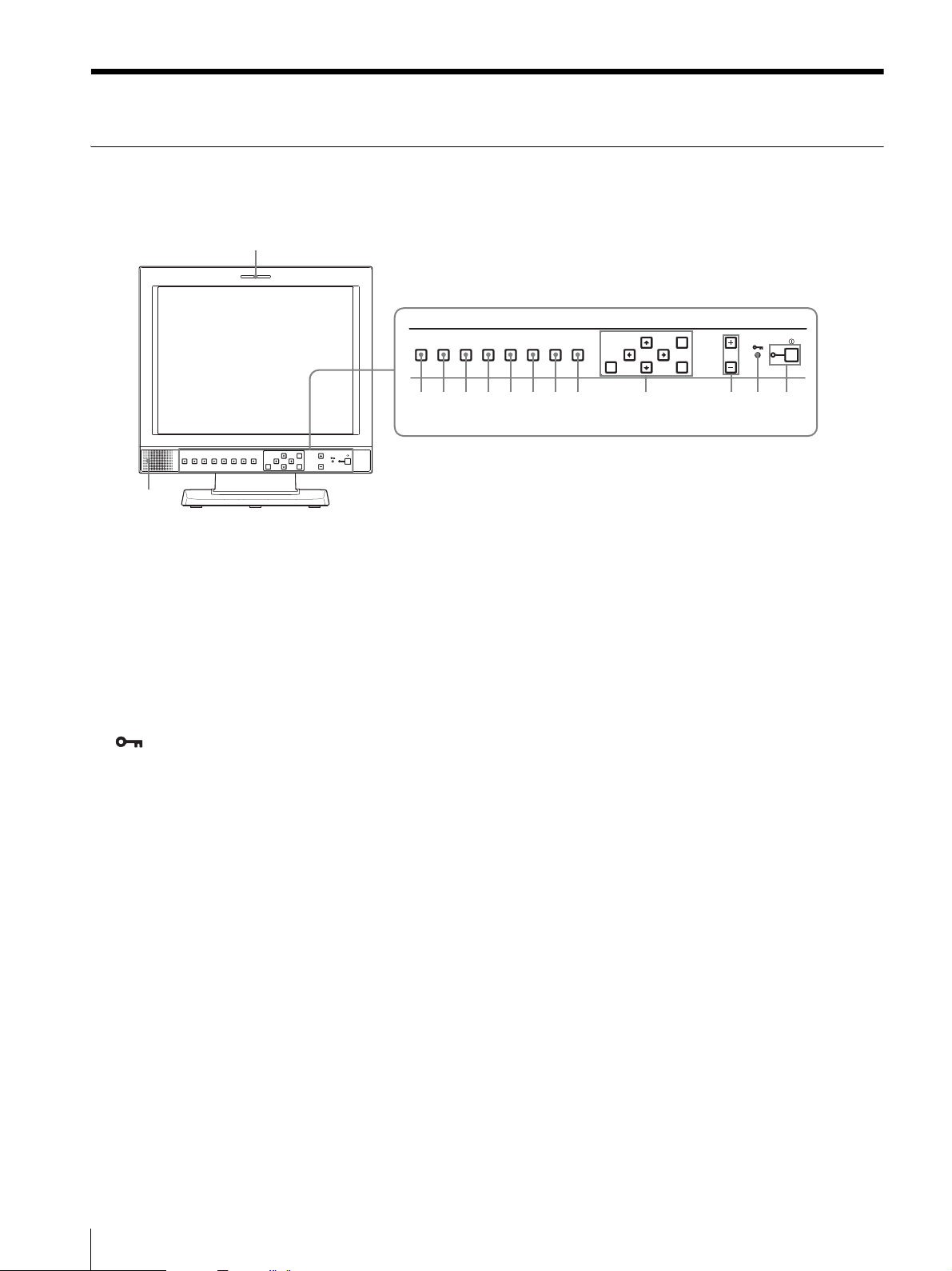
Front Panel
1
LINE A LINE B SDI SCAN ASPECT
qd
qs qa 0 9 8 7 6 5 4 3 2
RESET
MENU VOLUME POWER
ENTER
EXT
BLUE
RGB/
SYNC
LINE A LINE B SDI SCAN ASPECT
ONLY
COMPONENT
qf
a Tally lamp
The lamp lights in green when this unit is controlled
from the PARALELL REMOTE terminal on the rear
panel of the unit.
b POWER switch and indicator
Press to turn on the power. The indicator turns on. Press
again to turn off the power.
c KEY INHIBIT indicator
When the key inhibit function works, the indicator
lights.
For the key inhibit function, refer to “KEY INHIBIT
menu” on page 19.
d VOLUME buttons
Press the + button to increase the volume or the – button
to decrease it.
e Menu operation buttons
Displays or sets the on-screen menu.
M/m/</, (arrow) buttons
Select the menu or make various adjustments.
MENU button
Press to display the on-screen menu.
Press again to clear the menu.
RGB/
COMPONENT
EXT
BLUE
SYNC
ONLY
RESET
MENU VOLUME POWER
ENTER
RESET button
Resets the value of an item back to the previous
value. This button functions when the menu item is
adjusted (displayed) on the screen.
ENTER button
Press to confirm a selected item on the menu.
f ASPECT select button
Sets the aspect ratio of the picture, 4:3 or 16:9.
g SCAN select button
You can change the scan size of the picture. When you
press the button, the scan size is changed to normal (5%
over scan), under (-3% under scan) or ZOOM set on the
SCAN menu (see page 18).
h BLUE ONLY button
Press this button to eliminate the red and green signals.
Only blue signal is displayed as an apparent
monochrome picture on the screen. This facilitates
“chroma” and “phase” adjustments and observation of
VCR noise.
i EXT SYNC (external sync) button
Press to operate the unit on an external sync signal
through the EXT SYNC IN connector.
The EXT SYNC button works when the component/
RGB signals are input.
8
Location and Function of Parts and Controls
Page 9

j SDI button
Press to monitor the signal from the OPTION IN
connector.
m LINE A button
Press to monitor the signal through the IN (input)
connector of the LINE A connectors.
k RGB/COMPONENT button
Press to monitor the signal through the IN (input)
connector of the RGB/COMPONENT connectors.
n Speakers
The audio signal which is selected by the input select
button on the front panel is output.
l LINE B button
Press to monitor the signal through the IN (input)
connector of the LINE B connectors.
Input Signals and Adjustable/Setting Items
Input signal
Item Video, Y/C B & W Component RGB SDI
CONTRAST
BRIGHT
CHROMA
PHASE
APERTURE
COLOR TEMP
COMP LEVEL
NTSC SETUP
GAMMA
SCAN
ASPECT
BLUE ONLY
*
aaaaa
aaaaa
a
a (NTSC)
aaa
aaaaa
×
××× ×
××
a (NTSC) a (480/60I)
aaaaa
aaaaa
aaaaa
a
×
a
×
×
a
××
×× ×
aa a
D1
a
a
* When a component signal (480/60I) is input, this can
be switchable.
a : Adjustable/can be set
× : Not adjustable/cannot be set
Location and Function of Parts and Controls
9
Page 10

Rear Panel
9
LINE A
PARALLEL REMOTE RGB/COMPONENT
OUT
IN
LINE B
IN OUT
IN OUT
VIDEO
IN OUT
VIDEO
IN OUT
AUDIO
AUDIO
AC IN
IN OUT
IN OUT
IN OUT
OPTION
AUDIO IN
G/Y
B/P
R/P
OPTION IN
EXT
IN OUT
B
SYNC
IN OUT
AUDIO
R
a OPTION IN connector (D-sub 9-pin, female)
When optional SDI input adaptor BKM-320D is
connected, SDI signals are input.
Press the SDI button to monitor the signal.
Note
Do not install the equipment other than BKM-320D.
It causes to damage the unit or the equipment.
b OPTION AUDIO IN connector
If the BKM-320D is installed in the OPTION IN
connector, input an audio signal into this connector.
Press the SDI button to monitor the audio signal.
21345678
OPTION
AUDIO IN
EXT
IN OUT
SYNC
IN OUT
AUDIO
OPTION IN
AC IN
LINE A
IN
IN OUT
VIDEO
IN OUT
AUDIO
PARALLEL REMOTE RGB/COMPONENT
OUT
LINE B
IN OUT
VIDEO
IN OUT
AUDIO
IN OUT
G/Y
IN OUT
B/P
B
IN OUT
R/P
R
d RGB/COMPONENT connectors
Analog RGB signal or component (Y, P
B, PR) signal
input connectors and their loop-through output
connectors.
Press the RGB/COMPONENT button on the front panel
to monitor the signal input through these connectors.
G/Y, B/P
B, R/PR IN/OUT (BNC)
These are the input/output connectors for an analog
RGB and a component (Y, P
B, PR) signal. Unless
an external sync signal is input, the monitor is
synchronized with the sync signal contained in the
G/Y signal.
c EXT SYNC IN/OUT (external sync) connectors
(BNC)
Press the EXT SYNC button to use the sync signal
through this connector.
IN connector
When this unit operates on an external sync signal,
connect the reference signal from a sync generator
to this connector.
Note
When inputting a video signal with the jitters, etc.
the picture may be disturbed. We recommend using
the TBC (time base corrector).
OUT connector
Loop-through output of the IN connector. Connect
to the external sync input of video equipment to be
synchronized with this unit.
When the cable is connected to this connector, the
75-ohm termination of the input is automatically
released, and the signal input to the IN connector is
output from this connector.
AUDIO IN/OUT (RCA pin)
When using an analog RGB or a component signal
as a video signal, use these jacks for the input/
output of an audio signal. Connect them to the
audio input/output jacks on equipment such as a
VCR.
e PARALLEL REMOTE terminal (modular
connector)
Forms a parallel switch and controls the monitor
externally.
For safety, do not connect the connector for peripheral
device wiring that might have excessive voltage to this
modular connector.
For details on the pin assignment and factory setting
function assigned to each pin, see page 21.
f LINE B connectors
Line input connectors for composite video and audio
signals and their loop-through output connectors.
Press the LINE B button on the front panel to monitor
the signal input through these connectors.
10
Location and Function of Parts and Controls
Page 11

VIDEO IN/OUT (BNC)
These are the input/output connectors for a
composite video signal. Connect them to the
composite video input/output connectors on
equipment such as a VCR, video camera, or another
monitor.
AUDIO IN/OUT (RCA pin)
These are the input/output jacks for an audio signal.
Connect them to the audio input/output jacks on
equipment such as a VCR.
Installing to the Rack
1
Remove the screws (4) to remove the stand.
g LINE A connectors
Line input connectors for Y/C separate, composite video
and audio signals and their loop-through output
connectors.
Press the LINE A button on the front panel to monitor
the input signal through these connectors.
If you input signals to both Y/C IN and VIDEO IN, the
signal input to the Y/C IN is selected.
Y/C IN/OUT (4-pin mini-DIN)
These are the input/output connectors for a Y/C
separate signal. Connect them to the Y/C separate
input/output connectors on equipment such as a
VCR, video camera, or another monitor.
VIDEO IN/OUT (BNC)
These are the input/output connectors for a
composite video signal. Connect them to the
composite video input/output connectors on
equipment such as a VCR, video camera, or another
monitor.
AUDIO IN/OUT (RCA pin)
These are the input/output jacks for an audio signal.
Connect them to the audio input/output jacks on
equipment such as a VCR.
LINE A
PARALLEL REMOTE RGB/COMPONENT
OUT
IN
LINE B
IN OUT
IN OUT
VIDEO
IN OUT
AUDIO
IN OUT
VIDEO
AUDIO
AC IN
2
Attach the unit to the rack after attaching the
IN OUT
IN OUT
IN OUT
OPTION
AUDIO IN
G/Y
B/P
R/P
OPTION IN
EXT
IN OUT
B
SYNC
IN OUT
AUDIO
R
mounting bracket.
L
I
N
E
A
L
IN
E
R
G
B
B
/
C
O
M
P
O
N
E
N
T
S
D
E
I
X
T
S
Y
N
B
C
L
U
E
O
N
L
Y
S
C
A
N
A
S
P
E
C
T
M
E
N
U
R
E
S
E
T
V
O
L
U
M
E
E
N
T
E
R
P
O
W
E
R
h /I (Equipotential/Function Earth) terminal
(equipotential) terminal
Connects the equipotential plug.
I (function earth) terminal
Connects the earth cable.
i AC IN socket
Connect the supplied AC power cord.
Installing to the Rack
11
Page 12

Connecting the AC
Attaching the Input
Power Cord
Connect the supplied AC power cord as illustrated.
1
Plug the AC power cord into the AC IN socket on
the rear panel. Then, attach the AC plug holder
(supplied) to the AC power cord.
L
IN
E
A
IN
O
U
AC IN socket
AC
AC plug holder
(Supplied)
2
Slide the AC plug holder over the cord until it locks.
T
IN O
U
T
VIDEO
IN
I
NO
U
T
AUDIO
AC power cord
Adaptor
Before attaching the input adaptor, disconnect the power
cord.
Note
Do not install the equipment other than BKM-320D.
It causes to damage the unit or the equipment.
L
IN
E
A
I
N
O
U
T
I
N
O
U
T
VIDEO
AC
IN
I
N
O
U
T
AUDIO
To remove the AC power cord
Pull out the AC plug holder while pressing the lock
levers.
12
Connecting the AC Power Cord / Attaching the Input Adaptor
Page 13

Selecting the Default Settings
When you turn on the unit for the first time after
purchasing it, select the area where you intend to use this
unit from among the options.
The default setting values for each area
3
1
5
RGB/
LINE A LINE B SDI SCAN ASPECT
COMPONENT
RESET
RESET
MENU VOLUME POWER
ENTER
EXT
BLUE
SYNC
ONLY
MENU VOLUME POWER
ENTER
4
3
3
1NORTH AMERICA Low BETA7.5 7.5
2LATIN AMERICA
PAL&PAL-N AREA
NTSC&PAL-M AREA OTHER AREA Low BETA7.5 7.5
ARGENTINA Low SMPTE 0
PARAGUAY Low SMPTE 0
URUGUAY Low SMPTE 0
3AFRICA AUSTRALASIA
EUROPE MIDDLE-EAST
4ASIA EXCEPT JAPAN
NTSC AREA Low BETA7.5 7.5
PAL AREA Low SMPTE 0
5JAPAN High SMPTE 0
2
COLOR
TEMP
COMP
LEVEL
Low SMPTE 0
NTSC
SETUP
2~3 1
1
Press the POWER switch.
The power is turned on and the SELECT SETTING
screen appears.
1North America
S E L E C T S E T T I N G
x N O R T H A M E R I C A
• L A T I N A M E R I C A
• A F R I C A A U S T R A L A S I A
E U R O P E M I D D L E - E A S T
• A S I A E X C E P T J A P A N
• J A P A N
2
Press the M or m button to select the area where you
intend to use the unit and press the , or ENTER
button.
If you select either LATIN AMERICA or ASIA
EXCEPT JAPAN, one of the following screens
appears.
2 If LATIN AMERICA is selected:
2Latin America
3Africa Australia/New
Zealand, Europe, Middle
East, Russia
4Asia Except Japan
5Japan
L A T I N A M E R I C A
x P A L & P A L - N A R E A
A R G E N T I N A
P A R A G U A Y
U R U G U A Y
• N T S C & P A L - M A R E A
O T H E R A R E A
PAL&PAL-N area
Argentina
Paraguay
Uruguay
NTSC&PAL-M area
Other area
Selecting the Default Settings
13
Page 14

4 If ASIA EXCEPT JAPAN is selected:
Customers who will use this unit in the shaded
areas shown in the map below should select NTSC
AREA.
Other customers should select PAL AREA.
Selecting the Menu Language
You can select one of seven languages (English, French,
German, Spanish, Italian, Japanese, Chinese) for
displaying the menu and other on-screen displays.
The current settings are displayed in place of the x
marks on the illustrations of the menu screen.
A S I A E X C E P T J A P A N
x N T S C A R E A
• P A L A R E A
3
Press the M or m button to narrow the area further
NTSC area
PAL area
and then press the , or ENTER button.
The SELECT SETTING screen disappears and the
menu item settings suitable for the selected area are
applied.
Note
When you have selected the wrong area, set the
following items using the menu.
COLOR TEMP (on page 17)
COMP LEVEL(on page 18)
NTSC SETUP (on page 18)
See “The default setting values for each area” (on
page 13) on the setting value.
RGB/
LINE A LINE B SDI SCAN ASPECT
COMPONENT
RESET
EXT
BLUE
SYNC
ONLY
MENU VOLUME POWER
ENTER
RESET
MENU VOLUME POWER
ENTER
3~5 2 1
1
Press the POWER switch to turn on the unit.
2
Press the MENU button.
The menu appears.
The menu presently selected is shown as a yellow
button.
USER CONTROL
CONTROL
· CONTRAST x
· BRIGHT x
· CHROMA x
· PHASE x
· APERTURE xxx
14
Selecting the Menu Language
Page 15

3
Press the M or m button to select the USER
CONFIG 1/2 (User Configuration 1/2) menu, then
press the , or ENTER button.
The setting items (icons) in the selected menu are
displayed in yellow.
USER CONFIG (1/2) Rr
· RGB/COMP SEL xxxx
· COMP LEVEL xxxxx
· NTSC SETUP x
· GAMMA x
· FORMAT DISP xxxx
xLANGUAGE ENGLISH
4
Press the M or m button to select “LANGUAGE,”
then press the , or ENTER button.
The selected item is displayed in yellow.
5
Press the M or m button to select a language, then
press the ENTER button.
The menu changes to the selected language.
USER CONFIG (1/2) Rr
· RGB/COMP SEL xxxx
· COMP LEVEL xxxxx
· NTSC SETUP x
· GAMMA x
· FORMAT DISP xxxx
xLANGUAGE ENGLISH
Using the Menu
The unit is equipped with an on-screen menu for making
various adjustments and settings such as picture control,
input setting, set setting change, etc. You can also
change the menu language displayed in the on-screen
menu.
To change the menu language, see “Selecting the Menu
Language” on page 14.
The current settings are displayed in place of the x
marks on the illustrations of the menu screen.
RGB/
LINE A LINE B SDI SCAN ASPECT
COMPONENT
RESET
EXT
BLUE
SYNC
ONLY
MENU VOLUME POWER
ENTER
RESET
MENU VOLUME POWER
ENTER
To clear the menu
Press the MENU button.
The menu disappears automatically if a button is not
pressed for one minute.
2~4 1
1
Press the MENU button.
The menu appears.
The menu presently selected is shown as a yellow
button.
USER CONTROL
CONTROL
· CONTRAST x
· BRIGHT x
· CHROMA x
· PHASE x
· APERTURE xxx
2
Use the M or m button to select a menu, then press
the , or ENTER button.
The menu icon presently selected is shown in
yellow and setting items are displayed.
USER CONFIG (1/2) Rr
· RGB/COMP SEL xxxx
· COMP LEVEL xxxxx
· NTSC SETUP x
· GAMMA x
· FORMAT DISP xxxx
xLANGUAGE ENGLISH
Using the Menu
15
Page 16

3
Press the M or m button to select the item, then
press the , or ENTER button.
The item to be changed is displayed in yellow.
Note
If the menu consists of multiple pages, press M or
m to go to the desired menu page.
Adjustment Using the Menus
Items
4
Make the setting or adjustment on an item.
When changing the adjustment level:
To increase the number, press the M button.
To decrease the number, press the m button.
Press the ENTER button to confirm the number,
then restore the original screen.
When changing the setting:
Press the M or m button to change the setting.
Press the ENTER button to confirm the setting.
Notes
• An item displayed in blue cannot be accessed.
You can access the item if it is displayed in white.
• If the key inhibit has been turned on, all items are
displayed in blue. To change any of the items,
turn the key inhibit to OFF first.
For details on the key inhibit, see page 19.
To clear the menu
Press the MENU button.
The menu disappears automatically if a button is not
pressed for one minute.
The screen menu of this monitor consists of the
following items.
STATUS (the items indicate the
current settings.)
FORMAT
COLOR TEMP
GAMMA
COMP LEVEL
NTSC SETUP
RGB/COMP SEL
SCAN MODE
DISPLAY
OPTION
COLOR TEMP/BAL
COLOR TEMP
MANUAL ADJ
USER CONTROL
CONTROL
About the memory of the settings
The settings are automatically stored in the monitor
memory.
To reset items that have been adjusted
Pressing the RESET button while you are adjusting any
of the menu items resets the menu item to the previous
setting.
USER CONFIG
RGB/COMP SEL
COMP LEVEL
NTSC SETUP
GAMMA
FORMAT DISP
LANGUAGE
SCAN
PIC DELAY MIN
REMOTE PARALLEL
1 PIN
2 PIN
3 PIN
4 PIN
6 PIN
7 PIN
8 PIN
16
Adjustment Using the Menus
Page 17

KEY INHIBIT
KEY INHIBIT
Adjusting and Changing the Settings
STATUS menu
The STATUS menu is used to display the current status
of the unit. The following items are displayed:
STATUS (1/2) Rr
FORMAT xxxxx
xxxxxxxx
COLOR TEMP xxxx
GAMMA x
COMP LEVEL xxxxx
NTSC SETUP xx
RGB/COMP SEL xxxx
SCAN MODE xxxx
STATUS (2/2) Rr
DISPLAY
LMD-1420MD xxxxxxx
OPTION
BKM-320D
•Signal format
• Color temperature
• Gamma
• Component level
•NTSC setup
• RGB/COMP SEL
•Scan mode
•Display
•Option
Submenu Setting
COLOR TEMP Select the color temperature from
among HIGH, LOW, LOW2 and
USER setting.
• HIGH (D93 or equivalent)
• LOW (D65 or equivalent)
• LOW2 (D56 or equivalent)
•USER
MANUAL ADJ If you set the COLOR TEMP to
USER setting, the item displayed is
changed from blue to white, which
means you can adjust the color
temperature.
• ADJUST GAIN...: Adjusts the
color balance (GAIN).
• ADJUST BIAS...: Adjusts the
color balance (BIAS).
• COPY FROM: If you select
HIGH, LOW or LOW2, the
white balance data for the
selected color temperature
will be copied in the user
setting.
USER CONTROL menu
The USER CONTROL menu is used for adjusting the
picture.
Items that cannot be adjusted depending on the input
signal are displayed in blue.
USER CONTROL
CONTROL
xCONTRAST x
· BRIGHT x
· CHROMA x
· PHASE x
· APERTURE xxx
COLOR TEMP/BAL menu
The COLOR TEMP/BAL menu is used for adjusting the
picture white balance.
You need to use the measurement instrument to adjust
the white balance.
Recommended: Konicaminolta color analyzer CA-210
COLOR TEMP/BAL
xCOLOR TEMP xxxx
MANUAL ADJ
· ADJUST GAIN···
· ADJUST BIAS···
· COPY FROM xxx
Submenu Setting
CONTROL You can adjust the picture.
• CONTRAST: Adjusts the picture
contrast.
• BRIGHT: Adjusts the picture
brightness.
• CHROMA: Adjusts color intensity.
The higher the setting, the greater
the intensity. The lower the setting,
the lower the intensity.
• PHASE: Adjusts color tones. The
higher the setting, the more
greenish the picture. The lower the
setting, the more purplish the
picture.
• APERTURE: Adjusts the picture
sharpness. The higher the setting,
the sharper the picture.
For details of input signals and adjustable/
setting items, see page 9.
Adjustment Using the Menus
17
Page 18

USER CONFIG menu
You can select a language, etc.
Items that cannot be adjusted depending on the input
signal are displayed in blue.
USER CONFIG (1/2) Rr
x RGB/COMP SEL xxxx
· COMP LEVEL xxxxx
· NTSC SETUP x
· GAMMA x
· FORMAT DISP xxx
· LANGUAGE xxx
USER CONFIG (2/2) Rr
xSCAN xxxx
· P IC DELAY MIN xxx
Submenu Setting
SCAN Enlarge a 4:3 aspect ratio picture to
a 16:9 aspect ratio picture.
Select from “OFF” and “ZOOM”
mode.
PIC DELAY MIN Selects to set the delay by the
picture processing to the minimum
level when the signal is input.
• OFF: Mode for giving
precedence to the picture quality
(recommended mode). It takes
longer than “ON” for processing
the picture.
• ON: The processing time is
short. Line flicker and afterimage may be displayed.
Scan mode image
Input
Submenu Setting
RGB/COMP SEL When a signal input via the IN
(input) connector of the RGB/
COMPONENT connector is being
monitored, based on the signal
being input, select RGB or COMP.
COMP LEVEL Select the component level from
among three modes.
• SMPTE for 100/0/100/0 signal
• BETA 0 for 100/0/75/0 signal
• BETA 7.5 for 100/7.5/75/7.5
signal
NTSC SETUP Select the NTSC setup level from
two modes.
The 7.5 setup level is used mainly
in North America. The 0 setup level
is used mainly in Japan.
GAMMA Selects the appropriate gamma
mode. You can select from among
5 settings. When “3” is selected,
the setting is roughly same as the
gamma mode of the CRT (2.2).
FORMAT DISP Select the display mode of the
signal format.
• ON: The format is always
displayed.
• OFF: The display is hidden.
• AUTO: The format is displayed
for about 10 seconds when
the input of the signal
begins.
LANGUAGE You can select the menu or message
language from among seven
languages.
• ENGLISH: English
• DEUTSCH: German
• FRANÇAIS: French
• ITALIANO: Italian
• ESPAÑOL: Spanish
• : Japanese
• : Chinese
NORMAL
SCAN (5 %
OVERSCAN)
UNDER
SCAN
Output
ZOOM
4
3
4
9
3
16
16
9
–
18
Adjustment Using the Menus
Page 19

REMOTE PARALLEL menu
Select the PARALLEL REMOTE connector pins for
which you want to change the function.
You can assign various functions to 1 to 4 pins and 6 to
8 pins. The following lists the functions you can assign
to the pins.
REMOTE PARALLEL
x1PIN xxxxx
· 2PIN xxxxx
· 3PIN xxxxxxx
· 4PIN xxxxxxx
· 6PIN xxxxxxxx
· 7PIN xxxxxxxxx
· 8PIN xxxx
• – – – (“– – –”: No function is assigned.)
•LINE A
•LINE B
• RGB/COMP
•16:9
•4:3
• UNDER
• NORMAL
•ZOOM
•TALLY
• EXT SYNC
•BLUE ONLY
•SDI
Troubleshooting
This section may help you isolate the cause of a problem
and as a result, eliminate the need to contact technical
support.
• The display is colored in green or purple t By
pressing RGB/COMPONENT button, select the
correct input with the RGB/COMP SEL setting in the
USER CONFIG menu.
• The unit cannot be operated t The key protection
function works. Set the KEY INHIBIT setting to OFF
in the KEY INHIBIT menu.
Note
If you use the PARALLEL REMOTE function, you
need to connect cables. For more details, see page 21.
KEY INHIBIT menu
KEY INHIBIT
xKEY INHIBIT xxx
You can lock the setting so that they cannot be changed
by an unauthorized user.
Select OFF or ON.
If you set ON, all items are displayed in blue, indicating
the items are locked.
Troubleshooting
19
Page 20

Specifications
Picture performance
LCD panel a-Si TFT Active Matrix
Picture size 14 type
283 × 212 × 354 mm (W/H/
Diagonal) (11
Resolution 640 × 480 dots (VGA)
Viewing angle 85°/85°/85°/85° (typical)
Scan Under –3 %
Normal 5 %
Aspect ratio 4:3
Display color 16,200,000
Input/output connectors
Input
LINE A input connectors
Y/C input 4-pin mini-DIN (1)
VIDEO input
BNC type (1), 1 Vp-p
synchronization
AUDIO input
RCA pin (1), –5 dBu 47 kilohms or
higher
LINE B input connectors
VIDEO input
BNC type (1), 1 Vp-p
synchronization
AUDIO input
RCA pin (1), –5 dBu 47 kilohms or
higher
RGB/COMPONENT input connectors
BNC type (3)
RGB input 0.7 Vp-p
Component input
0.7 Vp-p
AUDIO input
RCA pin (1), –5 dBu 47 kilohms or
OPTION AUDIO input jacks
RCA pin (2), –5 dBu 47 kilohms or
EXT SYNC input connector
BNC type (1), 0.3 to 4 Vp-p
PARALLEL REMOTE input terminal
Parallel remote
Modular connector 8-pin (1)
±3 dB, (Sync On Green, 0.3
Vp-p negative sync.)
±3 dB, (75 % chrominance
standard color bar signal)
higher
higher
negative polarity binary
1
/4 × 83/8 ×14 inches)
±3 dB, negative
±3 dB, negative
Output
LINE A output connectors
Y/C output 4-pin mini-DIN (1), Loop-through,
with 75 ohms automatic terminal
function
VIDEO output
BNC type (1), Loop-through, with 75
ohms automatic terminal function
AUDIO output
RCA pin (1), Loop-through
LINE B output connectors
VIDEO output
BNC type (1), Loop-through, with 75
ohms automatic terminal function
AUDIO output
RCA pin (1), Loop-through
RGB/COMPONENT output connectors
RGB/Component output
BNC type (3), Loop-through, with
75 ohms automatic terminal
function
AUDIO output
RCA pin (1), Loop-through
EXT SYNC output connector
BNC type (1), Loop-through, with
75 ohms automatic terminal
function
Built-in speaker output
0.5 W (mono)
General
Power AC100 – 240 V, 50/60 Hz
Power consumption
Maximum: approx. 51 W
1.2 A – 0.6 A
Dimensions Approx. 343 × 354 × 264 mm (not
including the projection parts)
5
(13
/8 × 14 ×101/2 inches)
(w/h/d)
Mass Approx. 6.8 kg
(14 lb 16 oz)
Operating conditions
Temperature0 °C to 40 °C (32 °F to 104 °F)
Recommended temperature
20 °C to 30 °C (68 °F to 86 °F)
Humidity 30% to 85% (no condensation)
Pressure 700 hPa to 1060 hPa
20
Specifications
Page 21

Storage and transport conditions
Temperature–20 °C to 55 °C (–4 °F to 131 °F)
Humidity 0% to 90%
Pressure 700 hPa to 1060 hPa
Accessories supplied
AC power cord (1)
AC plug holder (2)
Instructions for Use (1)
CD-ROM (1)
Quick Reference (1)
When you First Use the Monitor (1)
Warranty Card (1)
Using the CD-ROM Manual (1)
Sales Companies Guide (1)
Optional accessories
Rack mount bracket MB-526
SDI input adaptor BKM-320D
Medical Specifications
Protection against electric shock:
Class I
Protection against harmful ingress of water:
Ordinary
Degree of safety in the presence of a flammable
anesthetic mixture with air or with oxygen or nitrous
oxide:
Not suitable for use in the presence of a flammable
anesthetic mixture with air or with oxygen or nitrous
oxide
Mode of operation:
Continuous
Wiring required to use the Remote Control
Connect the function you want to use with a Remote
Control to the Ground (Pin 5).
Design and specifications are subject to change without
notice.
Pin assignment
PARALLEL REMOTE terminal
1
8
Modular connector
(8-pin)
Pin number Functions
1 Designating LINE A input signal
2 Designating LINE B input signal
3 Designating RGB/COMPONENT input signal
4 16:9
5 GND
6 4:3
7 Selecting under
8 Selecting normal
You can allocate functions using the REMOTE
PARALLEL menu (see page 19).
Specifications
21
Page 22

Video signal formats
The unit is applicable to the following signal formats.
Input
System Total lines Active lines Frame rate Scanning format Aspect ratio Signal standard
575/50I (PAL) 625 575 25 2:1 interlace 16:9/4:3 EBU N10
(PAL: ITU-R BT.624)
480/60I (NTSC) 525 483 30 2:1 interlace 16:9/4:3 SMPTE 253M
Output
System Effective picture size Frame rate Scanning format
575/50I (PAL) 640 × 480 50 Progressive
480/60I (NTSC) 640 × 480 60 Progressive
When an optional input adaptor is installed, the unit is applicable to the following signal formats.
When BKM-320D is installed
Input
System Signal standard
575/50I ITU-R BT.656
480/60I SMPTE 259M
(NTSC: SMPTE 170M)
22
Specifications
Page 23

Dimensions
Front
343 (13 5/8)
EXT
BLUE
RGB/
SYNC
LINE A LINE B SDI SCAN ASPECT
ONLY
COMPONENT
RESET
MENU VOLUME POWER
ENTER
/2)165.9 (6
1
138.1 (5
/8)
5
/2)2.5
1
213.8 (8
/8)
1
(
Side
76.2
(3)
86.8 (3 1/2)
264.4 (10 1/2)
96.8 (3
)
4
/
3
67.7
(2
7
/8)
Rear
/16)
7
100 (4)
36 (1
Bottom
100 (4)
LINE A
PARALLEL REMOTE RGB/COMPONENT OPTION
IN OUT
IN OUT
VIDEO
AC IN
IN OUT
AUDIO
LINE B
IN OUT
VIDEO
IN OUT
AUDIO
IN OUT
IN OUT
IN OUT
AUDIO IN
G/Y
OPTION IN
EXT
IN OUT
B/P
B
SYNC
IN OUT
AUDIO
R/P
R
204.3 (8 1/8)
165.1 (6
216.3 (8
1
5
/2)
/8)
4-M5
(3)
76.2
)
8
/
5
114.6 (4
Unit: mm (inches)
Dimensions
23
Page 24

Sony Corporation
 Loading...