

Page 1

AIT Library
4-657-183-43(1)
Operating Instructions
Before operating the unit, please read this manual
thoroughly and retain it for future reference.
LIB-162
© 2001 Sony Corporation
Page 2

INFORMATION
You are cautioned that any changes or modifications not expressly approved in this manual could void your authority to
operate this equipment.
WARNING
To reduce the risk of fire or electric shock, do not expose this apparatus to rain or moisture.
To avoid electrical shock, do not open the cabinet. Refer servicing to qualified personnel only.
Caution
The mains plug on this equipment must be used to disconnect mains power.
Please ensure that the socket outlet is installed near the equipment and shall be easily accessible.
Notice
Use the power cord set approved by the appropriate testing organization for the specific countries where this unit is to be
used.
WARNING
Before performing any installation or maintenance procedures, be sure that the library power switch is in the off position
and that the power cord is disconnected from the library.
WARNING
The standalone library weighs around 20 kg (with 2 AIT drives installed). At least 2 people are needed to move or lift the
library. Make sure you install the rack-mount library in the lowest possible location in the rack. For best results, use a rack
with extension support legs.
INFORMATION
This equipment has been tested and found to comply with the limits for a Class B digital device, pursuant to Part 15 of the
FCC Rules. These limits are designed to provide reasonable protection against harmful interference in a residential
installation. This equipment generates, uses, and can radiate radio frequency energy and, if not installed and used in
accordance with the instructions, may cause harmful interference to radio communications. However, there is no guarantee
that interference will not occur in a particular installation. If this equipment does cause harmful interference to radio or
television reception, which can be determined by turning the equipment off and on, the user is encouraged to try to correct
the interference by one or more of the following measures:
• Reorient or relocate the receiving antenna.
• Increase the separation between the equipment and receiver.
• Connect the equipment into an outlet on a circuit different from that to which the receiver is connected.
• Consult the dealer or an experienced radio/TV technician for help.
All interface cables used to connect peripherals must be shielded in order to comply with the limits for a digital device
pursuant to Subpart B of Part 15 of FCC Rules.
If you have any questions about this product, please contact Sony Support Center written in the warranty card.
Declaration of Conformity
Trade Name: SONY
Model No.: LIB-162
Responsible Party: Sony Electronics Inc.
Address: 16530 Via Esprillo San Diego, CA. 92127 U.S.A.
Telephone No.: 858-942-2230
This device complies with Part 15 of the FCC Rules. Operation is subject to the following two conditions:
(1) This device may not cause harmful interference, and
(2) This device must accept any interference received, including interference that may cause undesired operation.
2
Page 3
ATTENTION
According to the EU Directives related to product safety, EMC and R&TTE the manufacturer of this product is Sony
Corporation, 1-7-1 Konan Minato-ku Tokyo, 108-0075 Japan. The Authorised Representative is Sony Deutschland
GmbH, Hedelfinger Strasse 61,70327 Stuttgart, Germany. For any service or guarantee matters please refer to the
addresses given in separate service or guarantee documents.
AUFMERKSAMKEIT
Im Sinne der EU Richtlinien bezüglich Produktsicherheit, EMV und R&TTE ist Sony Corporation, 1-7-1 Konan
Minato-ku Tokyo, 108-0075 Japan der Hersteller dieses Produktes. Bevollmächtigter ist Sony Deutschland GmbH,
Hedelfinger Strasse 61,D-70327 Stuttgart. Für Service oder Garantieangelegenheiten wenden Sie sich bitte an die in
separaten Service oder Garantiedokumenten angegebenen Adressen.
European Union Restriction of Hazardous Substances Directive compliant.
Entspricht der Richtlinie der Europäischen Union zur Beschränkung der Verwendung
gefährlicher Stoffe.
Für Kunden in Deutschland
Diese Ausrüstung erfüllt die Europäischen EMC-Bestimmungen für die Verwendung in folgender/folgenden Umgebung(en):
·Wohngegenden
·Gewerbegebiete
·Leichtindustriegebiete
(Diese Ausrüstung erfüllt die Bestimmungen der Norm EN55022, Klasse B.)
ACHTUNG
Zur Trennung vom Netz ist der Netzstecker aus der Steckdose zu ziehen, welche sich in der Nähe des Gerätes befinden muß
und leicht zugänglich sein soll.
HINWEIS
Maschinenlärminformations-Verordnung - 3. GPSGV, der höchste Schalldruckpegel beträgt 70 dB(A) oder weniger gemäss EN
ISO 7779.
Operating environment
Installation Horizontal
Temperature 10 °C to 35 °C
Relative Humidity 20% to 80% (no condensation)
Ratings Input Voltage 100 V - 120 V/200 V - 240 V
Frequency 50 / 60 Hz
Current 1.4 A - 0.7 A max.
Mass approx. 20 kg
Betriebsumgebung
Installation Horizontal
Temperatur 10 °C bis 35 °C
Relative Luftfeuchtigkeit 20% bis 80%
Elektrische
Daten
Masse ca. 20 kg
Eingangsspannung 100 V - 120 V/200 V - 240 V
Frequenz 50 / 60 Hz
Strom 1,4 A - 0,7 A max.
(nicht kondensierend)
3
Page 4

Table of Contents
Chapter 1 Introduction
Chapter 2 Installation
Overview.......................................................................7
Product Features and Functions ...............................8
Front ................................................................................ 8
Rear ................................................................................. 9
Inside (front) .................................................................11
System Structure.......................................................11
Compatible Data Cartridges .....................................12
AIT Cartridges ..............................................................12
Cleaning Cartridges....................................................... 13
Software .....................................................................13
Precautions ................................................................14
Overview.....................................................................15
Unpacking ..................................................................15
Checking the Package Contents..............................17
Preparing the Host Computer ..................................17
Installing the AIT library............................................18
Connecting the Power Cable....................................19
Connecting to the Host Computer ...........................19
Setting the DIP Switches ..........................................21
Connecting SCSI Peripheral Devices ......................22
Turning the Power On/Off.........................................22
Initial Setup ................................................................25
Setting the Date and Time............................................. 25
Setting the SCSI ID....................................................... 27
Setting the Cartridges.................................................... 28
Connecting to the Network ...........................................31
Chapter 3 Basic Usage
Overview.....................................................................36
Control Panel .............................................................36
Usage of the Control Panel ...........................................36
Viewing the Status Display........................................... 37
Menu Items ...................................................................38
Control Buttons .........................................................41
Warnings ....................................................................43
Errors..........................................................................43
Setting or Changing the Password..........................44
4
Page 5

Basic Settings............................................................45
Disabling the Display of the Date and Time Screen..... 45
Disabling the Life Warning Display ............................. 46
Setting the Bar Code .....................................................47
Setting the R-MIC Function.......................................... 48
Adjusting the Brightness of the LCD Panel.................. 49
Using the Sequential Mode ........................................... 50
Disabling the Buttons on the Front Panel...............51
Assigned Element Addresses ..................................52
Handling the Cartridges............................................52
Handling........................................................................ 52
Storing........................................................................... 53
Daily Maintenance .....................................................53
Chapter 4 Operating the AIT Library
Overview.....................................................................54
Using the Cartridges .................................................54
Taking Out the Cartridges............................................. 54
Replacing the Cartridges............................................... 58
Moving the Cartridges ..................................................65
Viewing Information Related to the AIT Library .....66
Viewing Cartridge Information .................................66
Chapter 5 Operating the AIT Drive
Overview.....................................................................68
Viewing Information Related to the AIT Drive.........68
Cleaning the AIT Drive ..............................................69
Chapter 6 Using the Library Administration Menu
Overview.....................................................................73
Library Administration Menu....................................74
Accessing Library Administration Menu.................74
Menu Items.................................................................76
System Configuration Menu.....................................76
Configuration ................................................................76
Network......................................................................... 78
SCSI ID ......................................................................... 80
Password .......................................................................82
Maintenance Menu ....................................................83
Life Count .....................................................................83
Error Count ...................................................................85
Sensor............................................................................ 86
History........................................................................... 87
Diagnostic .....................................................................89
Firmware Upload ..........................................................90
5
Page 6

Appendix
Information Menu ......................................................93
Information.................................................................... 93
Inventory ....................................................................... 94
If You Forget the Password ......................................95
Changing the Air Filter 1...........................................95
Changing the Air Filter 2...........................................97
Troubleshooting ........................................................98
Transporting the AIT Library ....................................99
Hardware Specifications.........................................100
Hardware..................................................................... 100
Data Storage Capacity................................................. 101
Optional Accessories (sold separately) ................102
SCSI Cable and Terminator Specifications...........102
SCSI Cable.................................................................. 102
SCSI Cable Length...................................................... 102
SCSI Specifications.................................................102
About SCSI Components ............................................ 102
About SCSI Bus .......................................................... 103
Error Code List ........................................................103
Other Messages.......................................................106
Index .........................................................................108
© 2001 Sony Corporation. All rights reserved.
Trademarks
• Sony, StorStation and Advanced Intelligent Tape are trademarks or registered trademarks of Sony Corporation in this
country, other countries, or both.
• Other product names are trademarks or registered trademarks of their respective owners in this country, other countries,
or both.
6
Page 7

Overview
Introduction
The LIB-162 is an AIT (Advanced Intelligent Tape) library with a built-in AIT
drive. Up to 16 cartridges can be set and used. The unit can also be connected
to, and used with, a workstation or server.
Up to 16 cartridges can be set
Up to 16 AIT cartridges can be set. Cartridges can be replaced from the front panel.
Since the AIT library has a built-in bar code reader, bar code labels can be used to
manage cartridges. The following types of cartridges can be used in this library:
LIB-162/A5 models
• AIT-5 Cartridge: can record up to 6400 GB of data
• AIT-4 Cartridge: can record up to 3200 GB of data
• AIT-3 Ex Cartridge: can record up to 2400 GB of data
• AIT-3 Cartridge: can record up to 1600 GB of data
Chapter
LIB-162/A4 models
• AIT-4 Cartridge: can record up to 3200 GB of data
• AIT-3 Ex Cartridge: can record up to 2400 GB of data
LIB-162/A3X models
• AIT-3 Ex Cartridge: can record up to 2400 GB of data
• AIT-3 Cartridge: can record up to 1600 GB of data
• AIT-2 Turbo Cartridge: can record up to 1280 GB of data
LIB-162/A3 models
• AIT-3 Cartridge: can record up to 1600 GB of data
• AIT-2 Cartridge: can record up to 800 GB of data
• AIT-1 Cartridge: can record up to 560 GB of data
LIB-162/A2 models
• AIT-2 Cartridge: can record up to 800 GB of data
• AIT-1 Cartridge: can record up to 560 GB of data
LIB-162/A1 models
• AIT-1 Cartridge: can record up to 560 GB of data
Chapter 1 Introduction
7
Page 8
Notes
• Cartridges that can be used vary according to the type of built-in drive.
• The memory capacity mentioned above assumes the use of all 16 AIT
cartridges, no compression.
• For combinations other than those mentioned above, refer to the attached sheet.
Up to two AIT drives can be installed
Up to two AIT drives can be installed and used. (One AIT drive is preinstalled.)
Since AIT drives are hot-swappable units, they can be added or replaced even
while the power is on. If you want to install an additional AIT drive, please
contact your dealer.
The AIT library can be remotely controlled
A browser can be used to configure individual settings. It can also be used to
view library and maintenance information.
LVD SCSI-compliant
The LIB-162/A5, LIB-162/A4, LIB-162/A3X, and LIB-162/A3 models are
Ultra 160 LVD SCSI-compliant, whereas the LIB-162/A2 and LIB-162/A1
models are Wide Ultra LVD SCSI-compliant.
Suitable for rack mounting
With the ACY-RK2 rack mounting kit (sold separately), the AIT library can be
installed on an EIA-standard, universal pitch 19-inch rack. Contact your dealer
for information about the rack mounting kit.
Product Features and Functions
Front
1 453267
STAND BY
1 453267
STAND BY
ERROR
MENU ENTER CANCEL
89
ERROR
CANCELENTERMENU
89
Chapter 1 Introduction
8
Page 9
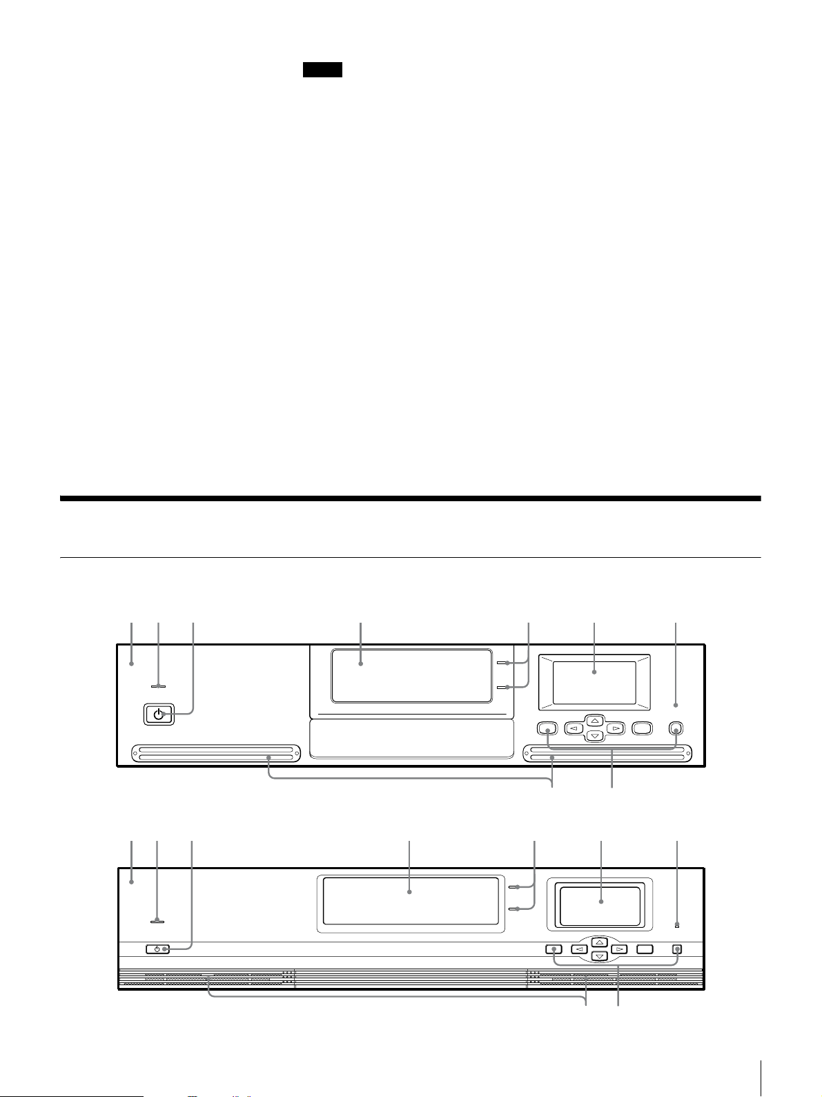
A Front Panel
There are two shapes for the front panel.
B Power Indicator LED
This LED light is on when the power is turned on.
C Power Standby Switch
Hold for five seconds or more to move the library’s internal mechanism to its
designated position and make it possible to turn the power off. Turn off the
library by pressing the power switch on the rear of the device.
(When preparing to move the device, press this switch, turn off the library by
pressing the power switch on the rear, and then set the transport lock and
transport screw in place on the bottom.)
D Cartridge Dock
Load and exchange cartridges in the cartridge dock. When the cartridge dock is
specified using the control buttons, its shutter opens automatically. The library
does not operate while the cartridge dock shutter is open, so close the shutter
using the control buttons after loading or exchanging cartridges.
E Cartridge Select LED
When loading or exchanging cartridges, the Cartridge Select LED light is on
next to the slot that you select with the control buttons. There are two slots: an
upper one and a lower one. Therefore, you can also use the cartridge in the slot
whose LED is not lit.
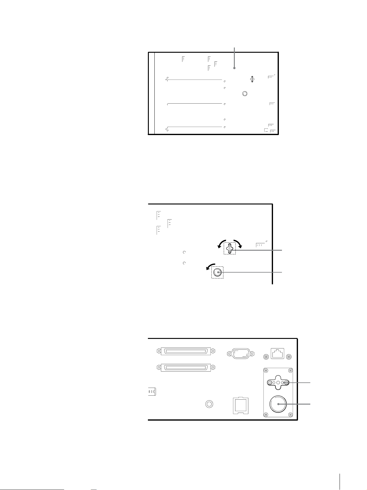
Rear
F Liquid Crystal Display
The LCD panel displays information such as the operating status. When in
normal standby state, it displays the status of the AIT library.
G Error LED
This LED light is on when an error occurs.
H Control Buttons
These buttons are used to control operations through the Control Panel Menu.
I Ventilation Holes
Please be careful not to block the ventilation holes. If the ventilation holes are
blocked, the AIT library may overheat, resulting in fire or other damage.
12 3 4 5 6 8 qa079
qs
qf qd
Chapter 1 Introduction
9
Page 10

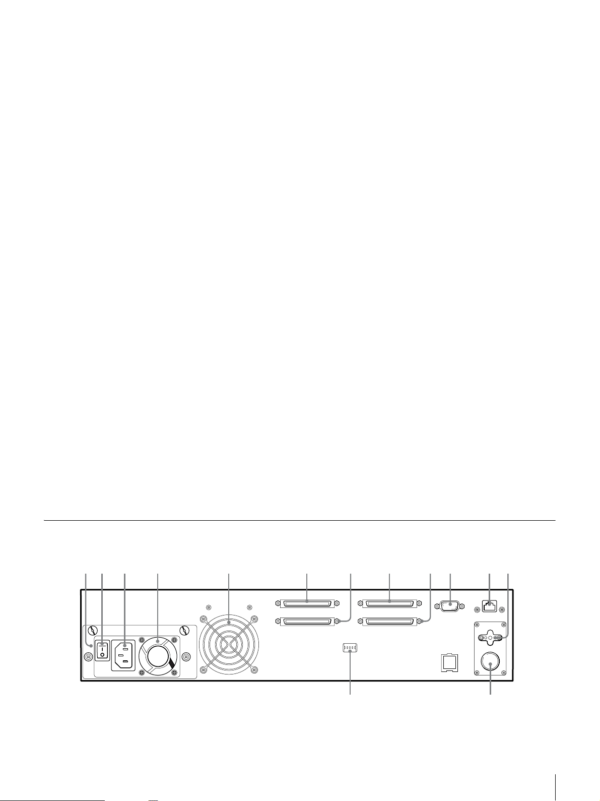
A Power Supply Unit
*
The power supply unit consists of a fan, a power supply connector, and a power
switch.
B Power Switch
*
Press this switch to turn the library on and off.
C Power Supply Connector
*
Plug the provided power cord into this connector.
D Fan 1
*
Please be careful not to block the ventilation holes. If the ventilation holes are
blocked, the AIT library may overheat, resulting in fire or other damage.
E Fan 2
Please be careful not to block the ventilation holes. If the ventilation holes are
blocked, the AIT library may overheat, resulting in fire or other damage.
F SCSI connector 1 7 SCSI connector 2 8 SCSI connector 3
9 SCSI connector 4
For information about connecting the SCSI connectors, refer to “Connecting to
the Host Computer” (page 19) and “Connecting SCSI Peripheral Devices” (page
22) in Chapter 2, “Installation”.
J Maintenance Connector
Used for maintenance purposes. Do not use.
K LAN Connector
Connect a 10Base-T network cable here.
L Transport Lock
Place for attaching the transport lock after removing it during installation.
M Transport Screw
Place for attaching the transport screw after removing it during installation.
N DIP Switches for Setup
The default factory setting of the DIP switches is as follows.
Use the DIP switches as is.
1: On
SCSI TERM POWER 1 (for SCSI connector 1 and SCSI connector 2 series)
2: On
SCSI TERM POWER 2 (for SCSI connector 3 and SCSI connector 4 series)
3: Not used
4: Not used
* Depending on the model, the layout may differ.
Chapter 1 Introduction
10
Page 11
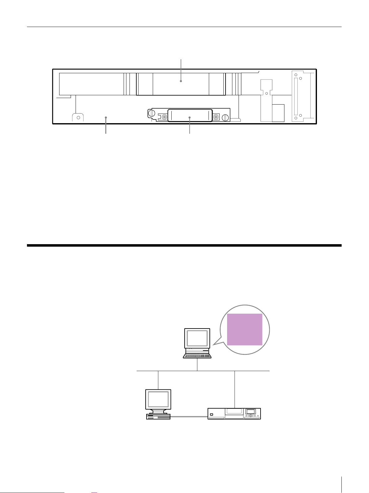
Inside (front)
1
23
A Cartridge Case (Library)
Up to 16 cartridges volumes can be set.
B AIT Drive 1 (R)
This drive is a standard built-in drive.
C Additional AIT drive slot (AIT Drive 2 (L))
Attach an additional AIT drive. Add a product of the same format as AIT Drive
1 (R).
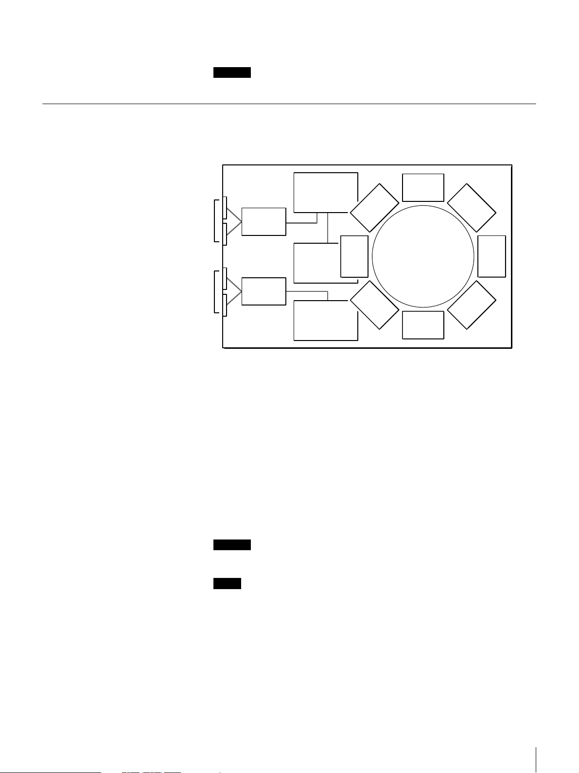
System Structure
Generally, the library is connected to the host computer and used to control the
library from the host computer. Also, you can connect the library to the network
so that it can be configured and maintained through a browser.
Make library settings and
perform maintenance.
Ethernet
Host computer
Control the
library.
SCSI
LIB-162
Chapter 1 Introduction
11
Page 12

Notes
• A SCSI host adapter card must be installed in the host computer.
• In order to configure and maintain the library through a browser, browser
software must be installed in the computer. The following operating systems
and browsers can be used safely with the library.
Operating systems:
- Microsoft Windows 95, Microsoft Windows 98, Microsoft Windows Me,
and Microsoft Windows 2000
Browsers:
- Microsoft Internet Explorer 5.01 or later
- Netscape Communicator 4.7 or later
Compatible Data Cartridges
This section describes data cartridges used in the AIT library.
AIT Cartridges
AIT cartridges for built-in AIT drives can be used in the AIT library. To achieve
the maximum transfer rate and recording capacity, use the optimum cartridges
for your type of AIT drive. For information on recording capacities, refer to
“Hardware Specifications” (page 100) in the “Appendix” chapter.
Built-in AIT-5 drive (LIB-162/A5 models)
AIT-5 mark AIT-3 Ex mark
AIT-4 mark
Built-in AIT-4 drive (LIB-162/A4 models)
AIT-4 mark AIT-3 Ex mark
Built-in AIT-3 Ex drive (LIB-162/A3X models)
AIT-1 mark*AIT-1 Turbo mark* AIT-E Turbo mark*
* Only supports read operations
Built-in AIT-3 drive (LIB-162/A3 models)
AIT-3 mark
AIT-2 mark*AIT-3 markAIT-3 Ex mark AIT-2 Turbo mark
AIT-2 mark AIT-1 markAIT-3 mark
Chapter 1 Introduction
12
Page 13

Cleaning Cartridges
Built-in AIT-2 drive (LIB-162/A2 models)
AIT-2 mark AIT-1 mark
Built-in AIT-1 drive (LIB-162/A1 models)
AIT-1 mark
Caution
• Do not use 8 mm video tapes sold at stores. An 8 mm video tape looks a lot
like an AIT cartridge, but has different specifications. Do not use any
cartridge other than those listed above. Use only designated AIT data
cartridges.
• For combinations other than those mentioned above, refer to the attached sheet.
To clean the AIT drive, use an AIT Cleaning cartridge. There are four types of
cleaning cartridges: the SDX5-CL for use with AIT-5 drives; SDX4-CL or
SDX4-CLL for use with AIT-4 drives; SDX3X-CL for use with AIT-3 Ex
drives; and SDX1-CL for use with AIT-3, AIT-2, and AIT-1 drives. Make sure
that you use the cleaning cartridge appropriate for your drive. For information
on cleaning, refer to “Cleaning the AIT Drive” (page 69) in Chapter 5,
“Operating the AIT Drive”.
Software
For guidance on application software that can be used with the AIT library and
supported operating systems, contact your dealer.
Chapter 1 Introduction
13
Page 14

Precautions
• Up to two AIT drives can be set and used in the AIT library. If you want to
use two AIT drives, use products with the same format. Using products with
different formats may result in an error.
• In the cartridge slots, use the optimum cartridges for the type of AIT drive
installed. Using cartridges other than an AIT cartridge (including cleaning
cartridges) may damage the library. For information about cartridges that can
be used with the AIT library, refer to “Compatible Data Cartridges” (page 12).
• Do not insert anything except AIT cartridges in the cartridge dock, as doing
so may result in damage.
• If the unit is suddenly taken from a cold to a warm location, or if ambient
temperature suddenly rises, moisture may form on the outer surface and/or
inside of the unit. This is known as condensation. If condensation occurs, put
the unit aside without turning it on and wait until the condensation clears. Do
not use the unit in such a state, as this may damage it.
Chapter 1 Introduction
14
Page 15

Overview
Unpacking
Installation
This chapter explains general procedures for positioning the AIT library,
connecting it to the host computer and turning on the library power. This chapter
also explains initial setup. Installation and setup steps may vary depending on
your system.
After turning on the power, make settings required to use the unit as explained
in “Initial Setup” (page 25).
Chapter
Note
You will need the box, packing materials, transport lock and transport screw if
you wish to move or transport the AIT library in the future. Retain them for
future use.
1
Remove the AIT library from the box as indicated on the box.
Remove the packing materials, such as plastic covers and tapes.
Caution
With two drives installed, the AIT library weighs approximately 20 kg
(44.1 lb.).
At least two people are needed in order to handle the library. Handling the AIT
library on your own could result in back injury or other accidents resulting in
injury or in damage to the AIT library.
Chapter 2 Installation
15
Page 16
2
Place the library standing up so that the bottom is visible.
Bottom
3
Remove the transport lock (1) and transport screw (2). To cover the holes,
affix the silver stickers provided to the positions marked by dotted lines in
the illustration below.
The transport lock (1) can be removed by turning it 90 degrees to the left
or right.
Remove the transport screw (2) by turning it counterclockwise.
90˚90˚
(1)*
(2)*
* When you remove the transport lock and transport screw, cover the holes
with the silver stickers provided.
4
Attach the transport lock (1) and the transport screw (2) to the rear of the
library.
(1)
(2)
Chapter 2 Installation
16
Page 17

Checking the Package Contents
After opening the package, make sure all of the following items are present.
Contact your dealer if anything is missing.
• LIB-162 AIT Library (1)
• Power cable (1)
• SCSI terminator (1)
• Quick Start Guide (1)
• Air Filter (4)
• Bar code label (1 sheet)
• Transport lock (fixed) (1)
• Transport screw (fixed) (1)
• Transport lock/screw sticker (silver) (2)
• Safety Notice (1)
Note
In addition to the above, other documentation, cables, and cleaning cartridges
may also be included.
Preparing the Host Computer
To prepare the host computer before installing the AIT library:
1
Make sure that a SCSI host adapter card is installed in the host computer.
2
Install the application software supporting the library on the host computer.
For guidance on application software that can be used with the AIT library
and supported operating systems, contact your dealer.
Chapter 2 Installation
17
Page 18
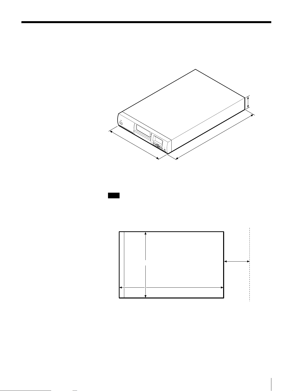
Installing the AIT library
The library weighs about 20 kg (44.1 lb.) and has the following dimensions.
Before installing the library, make sure that the surface on which you are placing
it is large and strong enough.
S
T
A
N
D
B
Y
430 mm (16.9 in.)
With the ACY-RK2 rack mounting kit (sold separately), the AIT library can be
installed on an EIA-standard, universal pitch 19-inch rack. Contact your dealer
for information about the rack mounting kit.
88 mm
(3.5 in.)
(2U)
M
E
N
U
E
E
R
N
R
T
O
E
R
R
C
A
N
C
E
L
680 mm (26.8 in.)
Note
Install the AIT library on a horizontal surface near an AC power outlet. Also,
leave a gap of about 150 mm (5.9 in.) behind the rear of the unit to allow air to
circulate.
Rear
150 mm
(5.9 in.)
Front 430 mm (16.9 in.)
680 mm (26.8 in.)
Chapter 2 Installation
18
Page 19
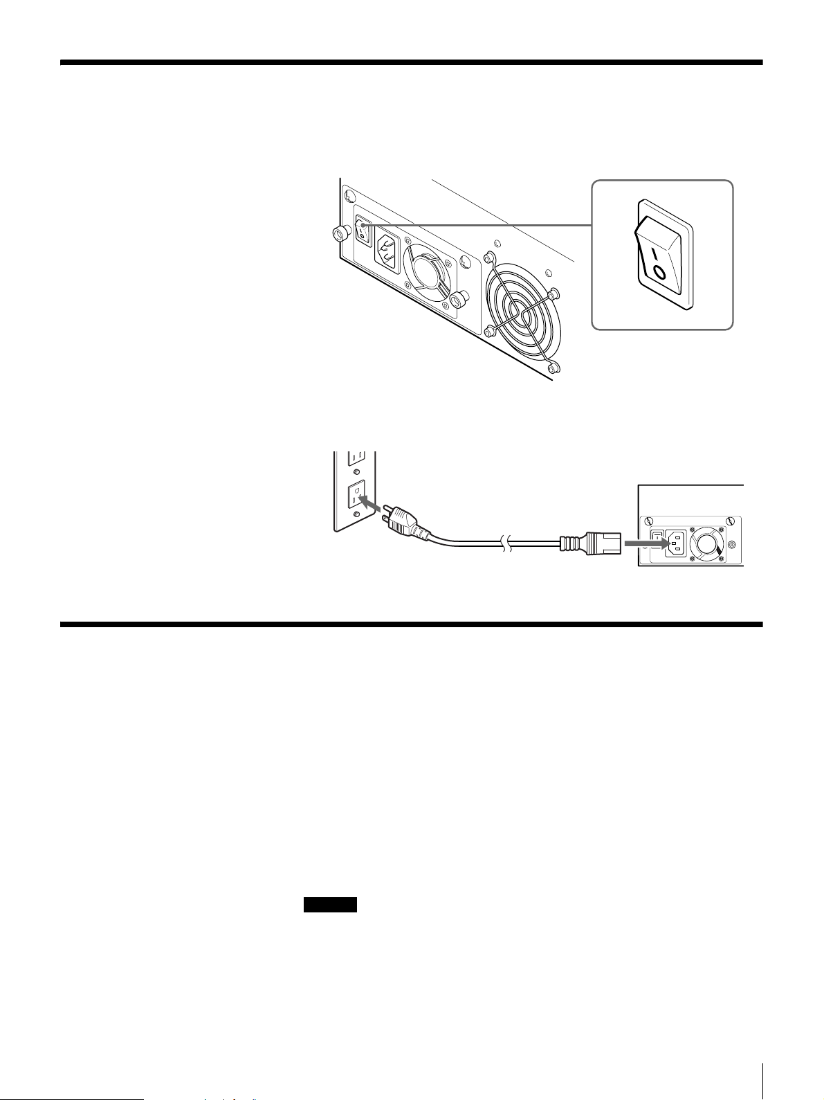
Connecting the Power Cable
1
Confirm that the power switch on the rear of the AIT library is turned off
(a is pressed).
2
Connect one end of the power cable to the power supply connector and the
other end to the power outlet.
Connecting to the Host Computer
Connect the AIT library and the host computer with a SCSI cable. This section
explains general connecting steps. Connect the library with the appropriate
SCSI cable, depending on the AIT drive.
• When the library is equipped with the AIT-5, AIT-4, AIT-3 Ex, or AIT-3
drive, use a commercially available Ultra 160 cable.
• When the library is equipped with the AIT-2 or AIT-1 drive, use a
commercially available Wide Ultra LVD SCSI cable that conforms to SCSI-3.
The library side uses the 68-pin half pitch connector.
When connecting other SCSI devices together with the AIT library, see
“Connecting SCSI Peripheral Devices” (page 22).
Caution
• Do not connect the AIT library to an HVD (High Voltage Differential) SCSI
bus. If connected, the library or other devices on the SCSI bus may be
damaged.
• When connecting a SCSI cable, turn off all the connecting devices, including
the host computer.
Chapter 2 Installation
19
Page 20
• When connecting the AIT library as the last device on a SCSI bus, be sure to
attach the provided terminator. Also, if the host computer is equipped with a
single-end SCSI host adapter, use a terminator that supports single-end. When
the wrong terminator is used, the device may be damaged.
• When using LVD (Low Voltage Differential) SCSI, make the length of the
SCSI cable that connects the host computer and the device at the end of the
SCSI bus shorter than 12 m (39 ft. 4.4 in.). When connecting the AIT library
to a single-ended SCSI host adapter, use a SCSI cable shorter than 1.5 m or
59 in.
• SCSI cables cannot be branched.
Notes
• For information about the SCSI bus, refer to “SCSI Specifications” (page 102)
in the “Appendix” chapter.
• Prepare the necessary SCSI cables. For information about SCSI cable
specifications, refer to “SCSI Cable and Terminator Specifications” (page
102) in the “Appendix” chapter.
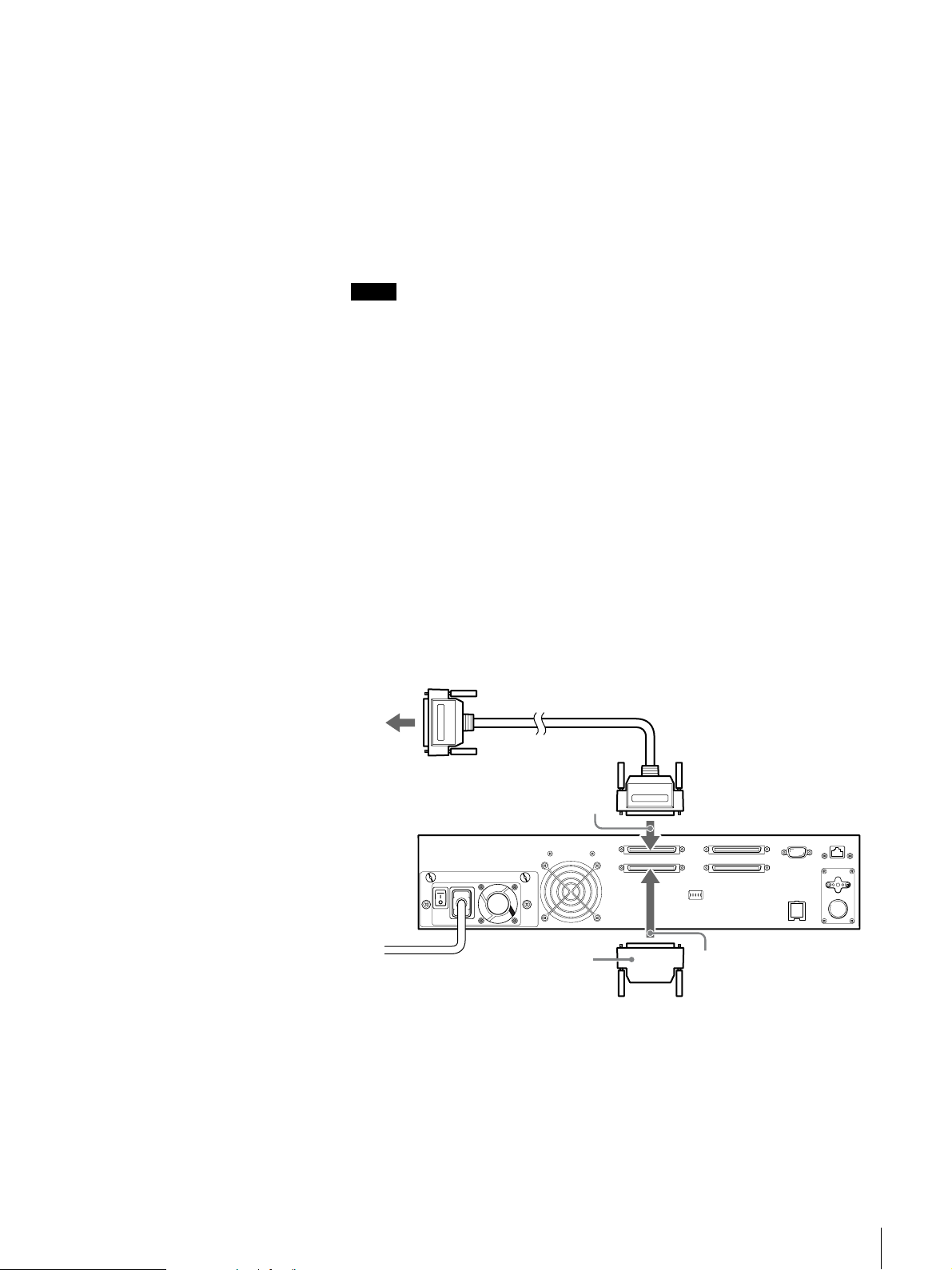
1
Confirm that the host computer and AIT library are turned off.
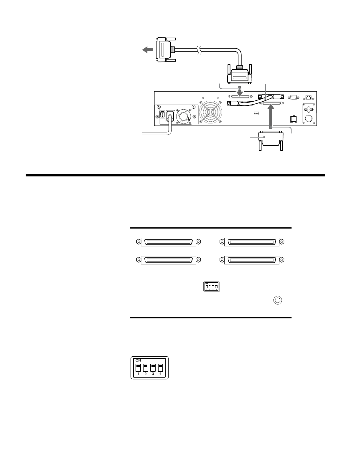
2
Attach the SCSI cable and terminator as shown in the figure below.
The manner in which it is attached varies with the number of internal
drives.
Host computer
When there is only one standard internal AIT drive (AIT drive is
not added):
1 Use a SCSI cable (sold at stores) to connect the AIT library to the host
computer.
2 Connect the SCSI cable to connector 1.
3 Attach the provided terminator to connector 2.
Nothing is connected to connector 3 and connector 4.
1
Terminator
2
When an AIT drive is added (there are two installed AIT drives):
1 Use a SCSI cable (sold at stores) to connect the AIT library to the host
computer.
2 Connect the SCSI cable to connector 1.
3 Connect the SCSI cable supplied with the supplementary AIT drive kit
from connector 2 to connector 3.
Chapter 2 Installation
20
Page 21
Host computer
4 Attach the provided terminator to connector 4.
Setting the DIP Switches
DIP switch settings determine whether electric power is supplied to the SCSI
terminator (when multiple SCSI devices are connected).
1
Terminator
2
3
The default factory setting of the DIP switches is as follows. To set the DIP
switches, use a pointed object such as a machinist’s screwdriver to change the
settings of the DIP switches.
1: On
SCSI TERM POWER 1 (for SCSI connector 1 and SCSI connector 2 series)
2: On
SCSI TERM POWER 2 (for SCSI connector 3 and SCSI connector 4 series)
3: Not used
4: Not used
Chapter 2 Installation
21
Page 22
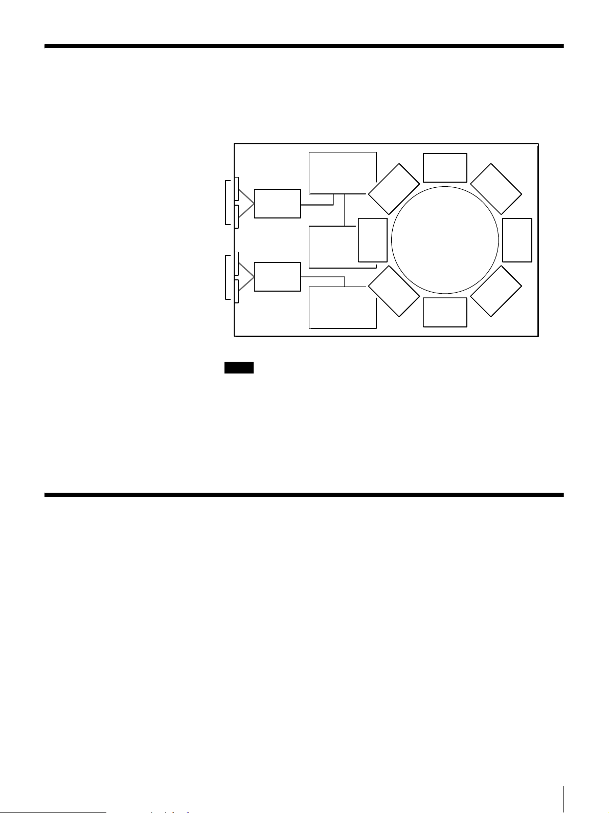
Connecting SCSI Peripheral Devices
SCSI peripheral devices can be connected to the SCSI connectors of the AIT
library. The SCSI configuration of the library is as shown below. Connect the
devices according to the system environment.
Library
Controller
SCSI Drive 1 (R)
SCSI Drive 2 (L)
SCSI BUS
Expander
AIT
Drive 1 (R)
SCSI BUS
Expander
AIT Drive 2 (L)
Notes
Library
• The default factory settings of the SCSI IDs are as follows.
- Library: 0
- AIT Drive 1 (R): 1
- AIT Drive 2 (L): 2
• Do not use repetitive SCSI IDs on the same SCSI bus.
• If the AIT Drive 2 (L) is not added, SCSI connector 3 and SCSI connector 4
cannot be used to connect SCSI devices.
Turning the Power On/Off
Turn the Power On
Turn on the AIT library power, then turn on the host computer power.
Some models must be turned on by pressing the power switch only, and other
models must be turned on by pressing the power switch, and then pressing the
standby switch.
Chapter 2 Installation
22
Page 23
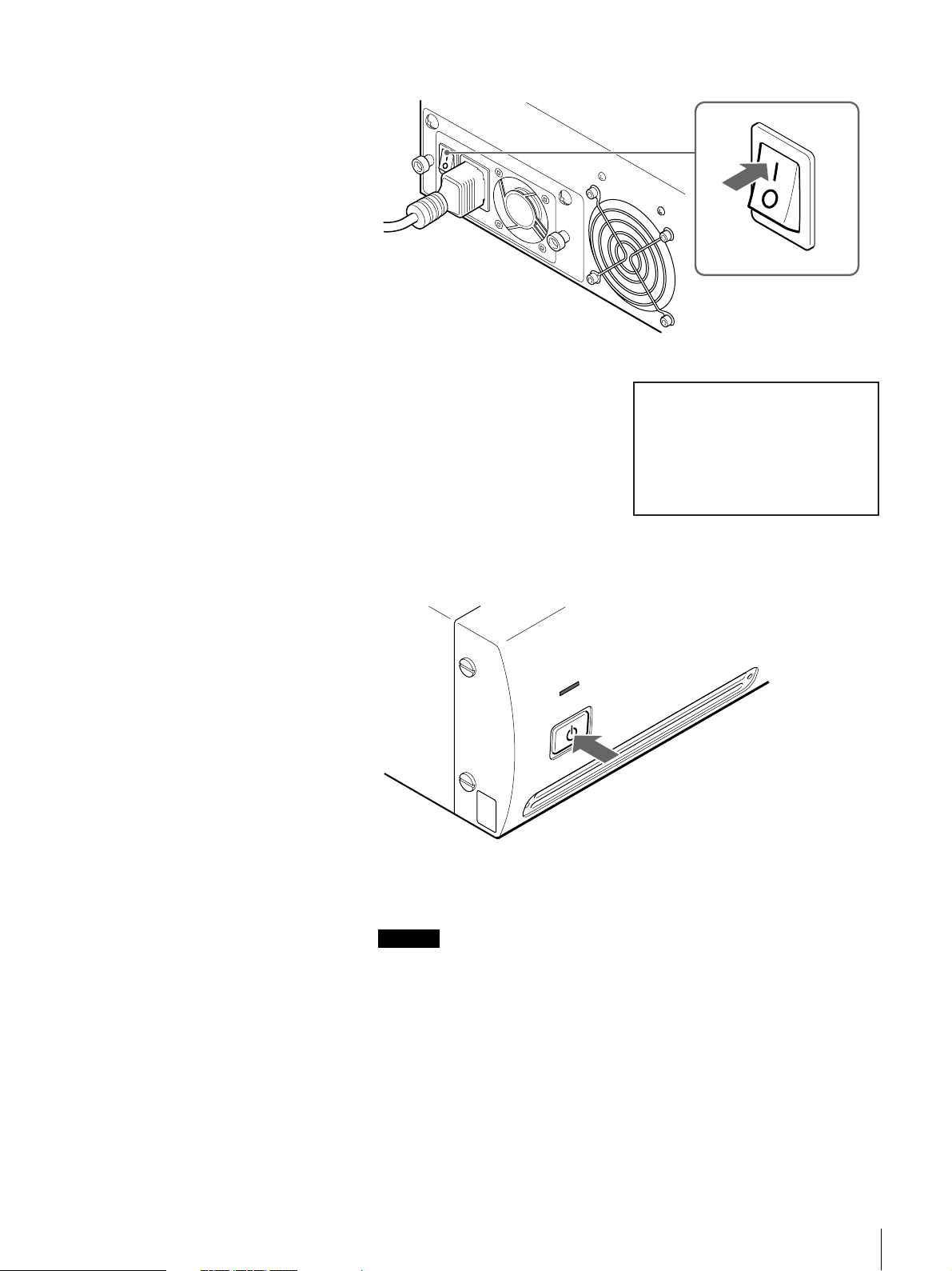
1
Press the power switch on the rear of the library.
The message on the right appears
and the startup process begins.
(Startup takes several minutes.)
LIB-162
Initializing····
If the message on the right does not appear, press the power standby switch
on the front panel for at least 3 seconds.
STAND BY
If the date and time screen appears at the end of the initialization process,
you can change the library’s date and time settings.
Caution
By default, the library is set to read bar codes. If you use cartridges without
bar code labels with this setting, initialization after turning on the library
takes unusually long. For details about how to set the library to read bar
codes, see “Setting the Bar Code” (page 47).
Chapter 2 Installation
23
Page 24
2
If you want to change the date and
time, press the [ENTER] button. If
you do not want to make changes,
press the [CANCEL] button.
• For details about the date and time
settings, see “Setting the Date and
Time” (page 25).
• You can change settings so that
the date and time screen does not
appear after startup. For details,
see “Disabling the Display of the
Date and Time Screen” (page 45).
Notes
• The date and time cannot be updated when the AIT library is off. For this
reason we recommend that you set the date and time each time you turn
on the library.
• If the library is left idle for five minutes, the status display appears
automatically.
Jan/01/2001
12:00:50
See the Date and Time
if necessary
[ENTER] to set
[CANCEL]to exit
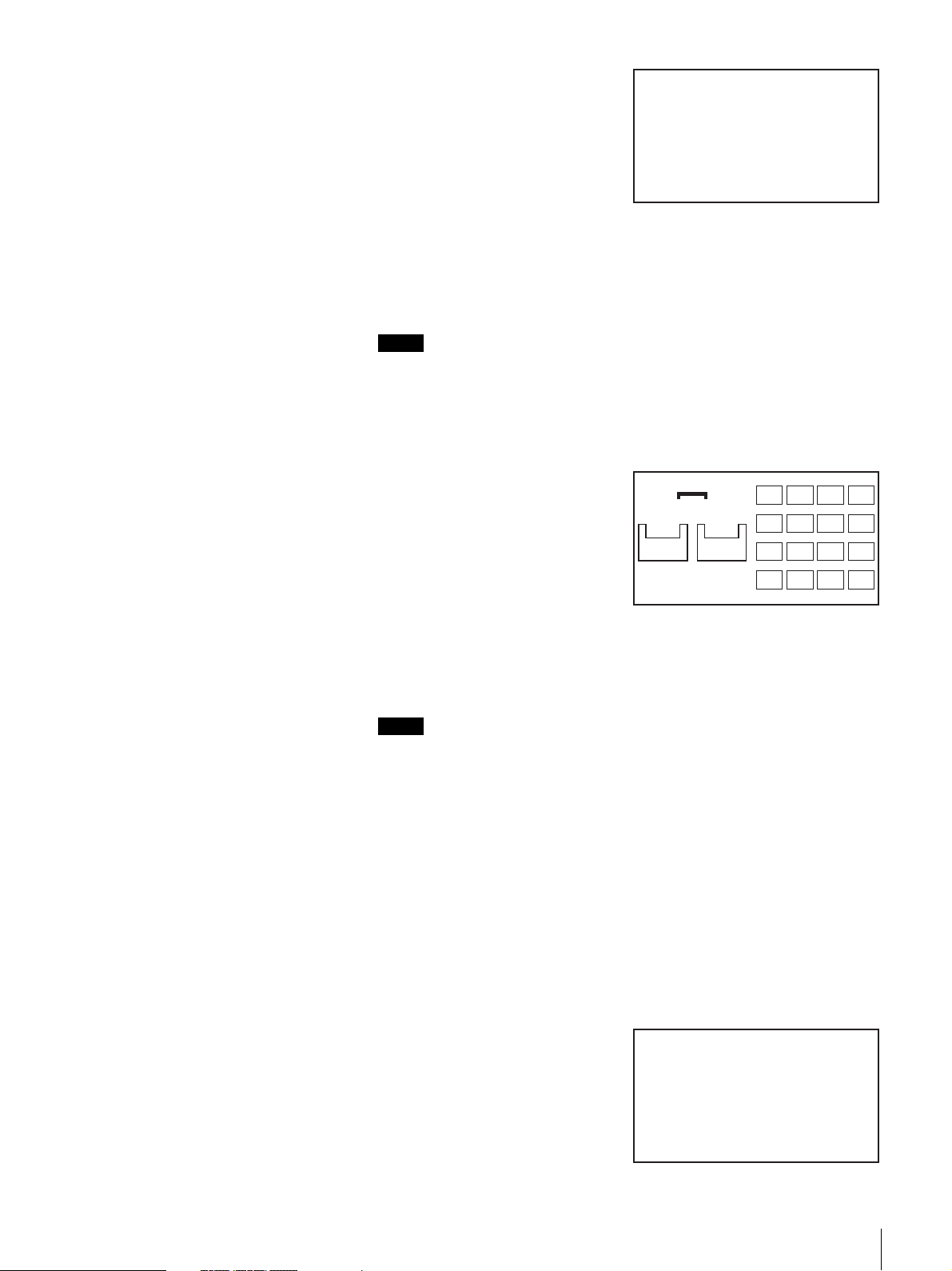
Turn the Power Off
Once the library is started, the status
screen on the right appears.
3
Wait at least 15 seconds after pressing the library’s power switch before
turning on the host computer.
When you are done, go to “Initial Setup” (page 25).
Notes
• If the host computer is turned on too soon after turning on the library, the
host computer may not detect the library’s SCSI IDs. Wait at least 15
seconds after turning on the library before turning on the host computer.
• If the library does not work as above, refer to “Troubleshooting” (page 98).
Some library models can be turned off only by pressing the standby switch.
Other models must be turned off by pressing the standby switch, and then the
power switch at the rear of the library.
READY
D2
AIT3
READY
D1
AIT3
READY
1 2 3 4
5 6 7 8
9101112
13 14 15 16
1
Press the power standby switch on the front panel at least 3 seconds.
When the power standby switch is pressed, the internal mechanism moves
to the predetermined position.
The message on the right appears.
Shutdown
+++ Wait a minute +++
Chapter 2 Installation
24
Page 25

2
When the message on the right
appears, turn off the library by
pressing the power switch on the
rear.
When transporting the library for
example, even if the message on the
right does not appear and the library
goes immediately on standby, press
the power switch on the rear of the
library to turn it off.
Caution
• You can turn off the library by pressing the power switch on the rear of the
library, but we urge you to perform the procedure above to turn off the library.
• After turning the AIT library off, wait at least 10 seconds before pressing the
power switch on the rear of the library to turn it back on. If you turn on the
library within 10 seconds of turning it off but it does not start, press the power
switch again to turn the library off, and wait at least 30 seconds before
attempting to turn it on again.
Note
To avoid pressing the power standby switch by accident, you can disable the
power standby switch. For information on how to disable the switch, refer to
“Disabling the Buttons on the Front Panel” (page 51).
Ready for shutdown
Press
the power switch
on the rear of the
Library
Initial Setup
Setting the Date and Time
Once the library has started, perform the initial setup as follows:
1
Set the date and time. (page 25)
2
Set the SCSI IDs of the AIT library and AIT drives if necessary. (page 27)
3
Set the cartridges. (page 28)
4
Configure the application programs on the host computer for use with the
unit.
Follow the instructions given in the application software manual to set up
the software for the library.
5
Connect to a network if necessary. (page 31)
Use the Configuration Menu of the control panel to set the current date and time.
Notes
• The date and time can also be set through a browser.
• The date and time cannot be updated when the AIT library is off.
1
At the status display, press the [MENU] button for two seconds.
Chapter 2 Installation
25
Page 26

2
Use the V and v buttons to select “5.Configuration”, then press the
[ENTER] button.
3
Select “1.Date & Time”, then press
the [ENTER] button.
4
When “Date & Time” appears, use
the V and v buttons to select “1. Set
Date & Time”, then press the
[ENTER] button.
Configuration 12:34
1.Date & Time
2.Warnig
3.Bar Code
4.R-MIC
5.LCD Contrast
6.Sequential Mode
Date & Time 12:34
1.Set Date & Time
2.Initial Setting
The date and time screen appears.
5
Set the month, day, and year.
1 When the month digits flash, use the V and v buttons to set the month,
then press the B button.
2 When the day digits flash, use the V and v buttons to set the day, then
press the B button.
3 When the year digits flash, use the V and v buttons to set the year.
4 After setting the month, day, and year, press the [ENTER] button.
6
Set the hour, minute, and second.
1 When the hour digits flash, use the V and v buttons to set the hour, then
press the B button.
2 When the minute digits flash, use the V and v buttons to set the minute,
then press the B button.
3 When the second digits flash, use the V and v buttons to set the second.
4 After setting the hour, minute, and second, press the [ENTER] button.
Date & Time 12:34
Date Jan/01/2001
Time 10:10:10
Time Zone
Japan
(GMT+ 9:00)
7
When “Time Zone” flashes, use the V and v buttons to set the country, then
press the [ENTER] button.
8
When “[ENTER] to activate”
appears, press the [ENTER] button.
The date and time and the country
are now set. The display returns to
“Date & Time”.
Date & Time 12:34
Date Jan/01/2001
Time 10:10:10
Time Zone
Japan
(GMT+ 9:00)
[ENTER] to activate
Chapter 2 Installation
26
Page 27
Setting the SCSI ID
9
Press the [CANCEL] button three times to return to the status display.
Caution
If you turn off the library, the displayed time is no longer correct.
Use the SCSI Menu of the control panel to set the SCSI IDs and SCSI parity of
the AIT library and AIT drives.
Library
Controller
SCSI Drive 1 (R)
SCSI Drive 2 (L)
SCSI BUS
Expander
AIT
Drive 1 (R)
SCSI BUS
Expander
AIT Drive 2 (L)
Library
About SCSI ID
For each SCSI device, a unique SCSI ID must be set for the AIT library and AIT
drives. The default factory settings of SCSI IDs are as follows:
• Library: 0
• AIT Drive 1 (R): 1
• AIT Drive 2 (L): 2
About SCSI parity
When the SCSI parity function is enabled, parity checks are performed on all
data passing through the SCSI bus. The factory default settings for SCSI parity
are as follows:
• Library: Enabled (YES)
• AIT Drive 1 (R): Enabled (YES)
• AIT Drive 2 (L): Enabled (YES)
Caution
Do not duplicate SCSI IDs on the same SCSI bus.
Notes
• Even if you do not add an AIT drive, make sure not to duplicate the SCSI ID
of Drive 2 (L).
• The SCSI IDs can also be set through a browser.
1
At the status display, press the [MENU] button for two seconds.
2
Use the V and v buttons to select “4.SCSI”, then press the [ENTER]
button.
Chapter 2 Installation
27
Page 28
3
Set the SCSI ID and SCSI parity of
the library.
1 When the “ID” of “Library”
setting flashes, use the V and v
buttons to set the SCSI ID, then
press the [ENTER] button.
2 When the “Parity” setting flashes,
use the V and v buttons to set the
SCSI parity, then press the
[ENTER] button.
Select “YES” to enable the SCSI
parity function.
4
In the same manner, set the Drive 2 (L).
If an AIT drive is not added, press the [ENTER] button to proceed.
5
When “[ENTER] to activate”
appears, press the [ENTER] button.
SCSI 12:34
ID Parity
Library 00 YES
Drive1 01 YES
Drive2 02 YES
SCSI 12:34
ID Parity
Library 00 YES
Drive1 01 YES
Drive2 02 YES
[ENTER] to activate
Setting the Cartridges
Preparing the Cartridge
6
When “[Enter] to reset” appears,
press the [ENTER] button.
The system reboots.
Prepare a cartridge and set it into the AIT library.
Affix the provided bar code label to the cartridge, then prepare it for use.
Caution
By default, the library is set to read bar codes. If you use cartridges without bar
code labels with this setting, initialization after turning on the library or using
the cartridges becomes unusually long. To extenuate this problem, use
cartridges with bar code labels or change the library setting not to read bar
codes. For details about the latter procedure, see “Setting the Bar Code” (page
47).
Warning 12:34
Reboot the system to
activate the setting
[ENTER] to reset
Note
The type of bar code label is fixed to Code 39 with check digit. This setting
cannot be changed. We recommend that you use the optional bar code labels
presented in “Optional Accessories (sold separately)” (page 102). When using
other bar codes, the library may not be able to read them.
Chapter 2 Installation
28
Page 29
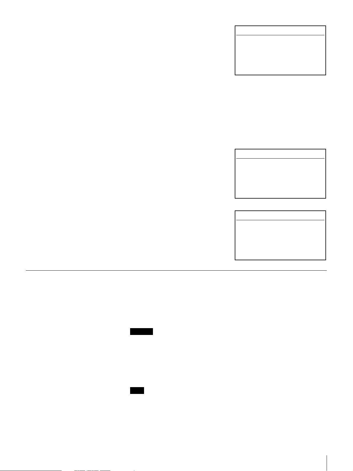
1
Affix the provided bar code label to the cartridge.
Squarely affix the barcode label in the position shown in the figure,
orienting it so that the numbers are at the top.
Bar code label
2
Check whether the erase-protection tab is set to the write-enable position.
If the tab is orange, data can be written to the cartridge.
Setting the Cartridge
AIT-1
Lid
If the tab is moved to the left, data
can be written to and erased from
the cartridge.K
If the tab is moved to the right, data
cannot be written or accidentally
erased from the cartridge.k
AIT-5, AIT-4, AIT-3 Ex, AIT-3, AIT-2 Turbo,
AIT-2, AIT-1 Turbo, AIT-E Turbo
Lid
If the tab is lowered, data can be
written to and erased from the
cartridge.j
If the tab is raised, data cannot be
written to or accidentally erased
from the cartridge.J
Set the cartridge into the AIT library. When setting the cartridge, specify the slot
by its element address. For information about element addresses, refer to
“Assigned Element Addresses” (page 52) in Chapter 3, “Basic Usage”.
1
At the status display, press the [MENU] button for two seconds.
2
Use the V and v buttons to select “2.Eject/Insert Tape”, then press the
[ENTER] button.
“Eject/Insert” appears.
3
Select “3.Insert Into Library”, then
press the [ENTER] button.
Eject/Insert 12:34
1.Eject From Library
2.Eject From Drive
3.Insert Into Library
Chapter 2 Installation
29
Page 30
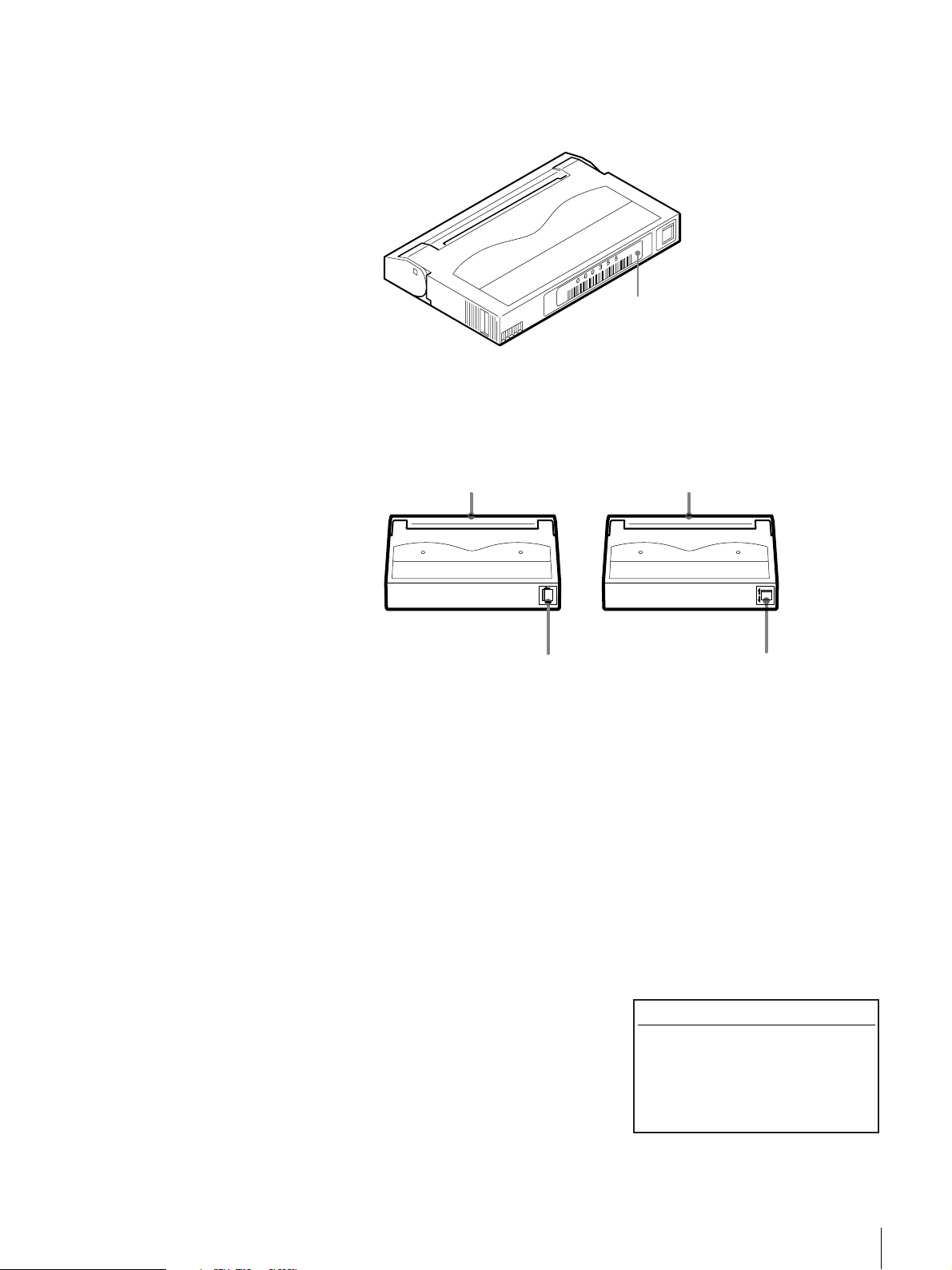
4
Use the V and v buttons to set the element address of the slot where the
cartridge is going to be set, then press the [ENTER] button.
5
When “[ENTER] to activate”
appears, press the [ENTER] button.
Insert Tape 12:34
Library 01
[ENTER] to activate
The cartridge dock shutter opens and the LED next to the specified slot is
lit.
R
E
T
N
E
U
N
E
M
L
E
C
N
A
C
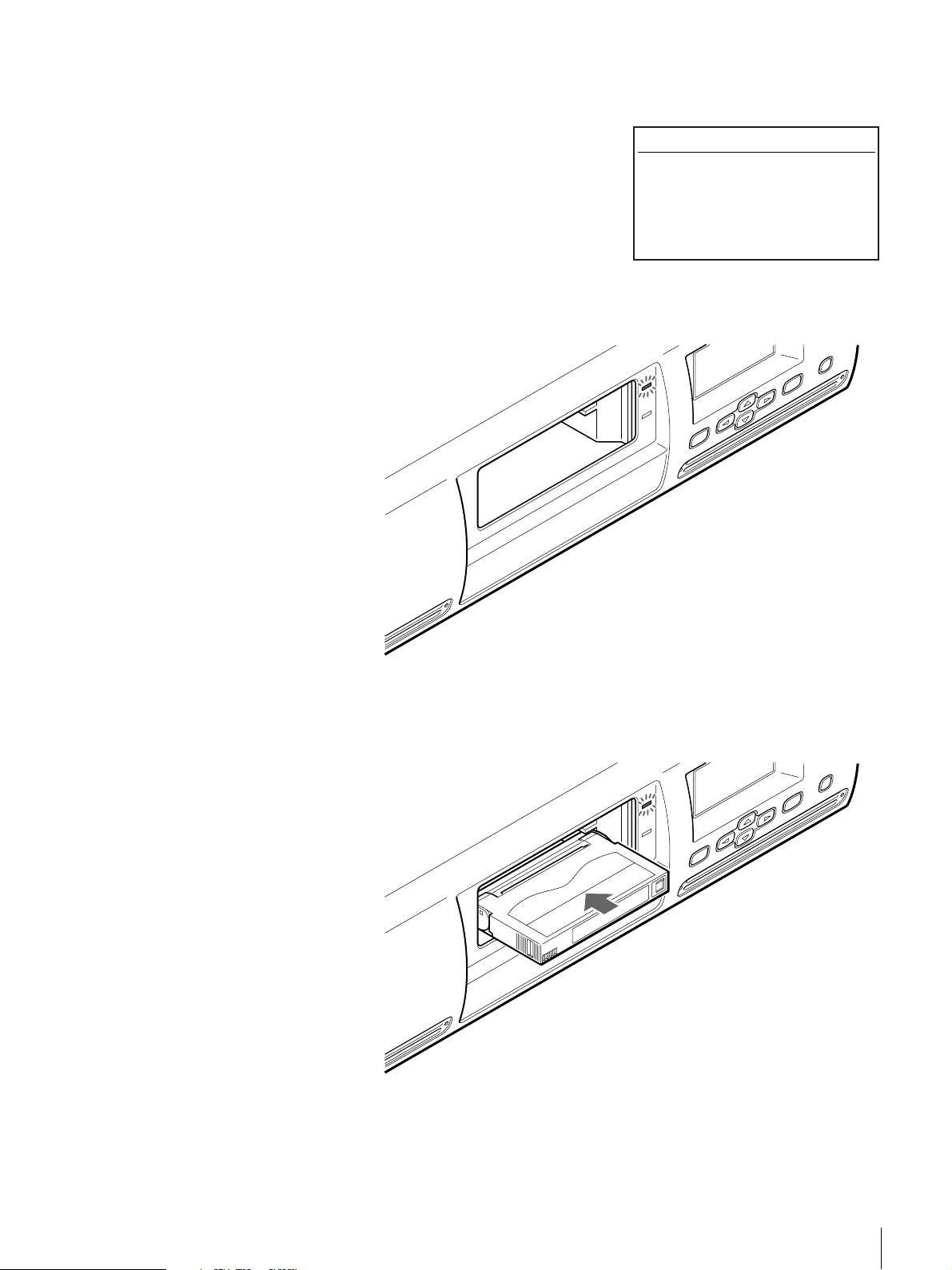
6
Insert the cartridge in the slot with the lit LED next to it.
Be sure to insert it all the way.
L
E
C
N
A
C
R
E
T
N
E
U
N
E
M
Chapter 2 Installation
30
Page 31

“Insert Tape ?” appears.
Note
Because the library is equipped with
two superimposed cartridge slots,
you can also insert a cartridge in the
slot whose LED is not lit.
Therefore, even if you specified slot
1 and opened the shutter, you can
still insert a cartridge in slot 2.
7
To set another cartridge, use the v
or V to set the element address of
the slot that is going to be set, then
press the [ENTER] button.
The cartridge dock shutter opens.
Insert the cartridge in the same
manner as above.
8
When all the cartridges are set,
press the B button, then press the
[ENTER] button.
Insert Tape 12:34
Library 01
Insert Tape ?
to set
to exit
to set
Insert Tape 12:34
Library 01
Insert Tape ?
to set
to exit
to set
[ENTER] to activate
Insert Tape 12:34
Library 01
Insert Tape ?
to set
to exit
to set
Connecting to the Network
The shutter closes and the LED dims.
9
Press the [CANCEL] button twice to return to the status display.
If the AIT library is connected to the network, a browser can be used to
configure the library and view status information.
Connect the AIT library to the network as follows.
1
Setup the network.
2
Connect a network cable.
3
Restart the library.
4
Access the library from a browser.
Notes
• For information about how to use the browser to configure individual settings
and view status information, refer to Chapter 6, “Library Administration
Menu” (page 74).
• In order to configure and maintain the library through a browser, browser
software must be installed in the computer. You can use the library with the
following operating systems and browsers.
Operating systems:
Chapter 2 Installation
31
Page 32

Setting the Network
- Microsoft Windows 95, Microsoft Windows 98, Microsoft Windows Me,
and Microsoft Windows 2000
Browsers:
- Microsoft Internet Explorer 5.01 or later
- Netscape Communicator 4.7 or later
In order to connect to the network, use the Network Menu of the control panel
to configure the necessary settings, such as the IP address setting.
Notes
• After connecting to the network, a browser can be used to change network
settings.
• The library does not support DNS, so there is no need to set “Host”,
“Domain”, “DNS1”, or “DNS2” below.
1
At the status display, press the [MENU] button for two seconds.
2
Use the V and v buttons to select
“6.Network”, then press the
[ENTER] button.
Menu 12:34
1.Information
2.Eject/Insert Tape
3.Move Tape
4.SCSI
5.Configuration
6.Network
“Network” appears.
3
When the “Host” setting flashes, set the host name. However, because the
library does not support DNS, this setting is unnecessary.
If no setting has been made, a flashing rectangle appears.
• In order to change the host name, use the V button, the v button, the B
button and the b button to enter the new host name, then press the
[ENTER] button. First, make sure that the same host name does not exist
in the same network, then enter the host name.
- Alphanumeric characters and symbols (! @ # $ % ( ) - { } ~ ") can be
used. Enter the host name, up to 64 characters.
- To delete a character, use space (“ ”).
• If you do not wish to change the host name, press the [ENTER] button.
4
When the “Domain” setting flashes, set the domain name. However,
because the library does not support DNS, this setting is unnecessary.
Network 12:34
Host
x
If no setting has been made, a flashing rectangle appears.
Chapter 2 Installation
32
Page 33

• In order to change the domain name, use the V button, the v button, the
B button and the b button to enter the new host name, then press the
[ENTER] button.
- Alphanumeric characters and symbols (! @ # $ % ( ) - { } ~ ") can be
used. Enter the domain name, up to 64 characters.
- To delete a character, use space (“ ”).
• If you do not wish to change the domain name, press the [ENTER]
button.
5
When the “DNS1” setting flashes, press the [ENTER] button.
However, because the library does not support DNS, this setting is
unnecessary.
6
When the “DNS2“ setting flashes, press the [ENTER] button.
However, because the library does not support DNS, this setting is
unnecessary.
7
When the “Gateway” setting flashes, use the V button, the v button, the B
button and the b button to set the IP address for the default gateway, then
press the [ENTER] button.
If no setting has been made, a flashing rectangle appears.
8
When the “DHCP” setting flashes, use the V and v buttons to select either
“YES” or “NO”, then press the [ENTER] button.
• Select “YES” to use the IP address assigned to the DHCP server. Then
proceed to step 12.
• Select “NO” to use the fixed IP address. Then proceed to step 10.
9
When the “IP Address” setting flashes, use the V button, the v button, the
B button and the b button to set the IP Address, then press the [ENTER]
button.
If no setting has been made, a flashing rectangle appears.
10
When the “Subnet Mask” setting flashes, use the V button, the v button,
the B button and the b button to set the subnet mask, then press the
[ENTER] button.
If no setting has been made, a flashing rectangle appears.
11
When “[ENTER] to activate”
appears, press the [ENTER] button.
Each of the items of the network is
now set. The display returns to
“Network”.
12
Press the [CANCEL] button to return to the status display.
Network 12:34
DHCP NO
IP Address
192.168.0.1
Subnet Mask
255.255.255.0
[ENTER] to activate
13
Press the power standby switch on the front panel to set the power of the
library to the standby state.
Chapter 2 Installation
33
Page 34

Connecting a Network Cable
After setting the network and setting the AIT library power to the standby state,
connect a network cable.
1
Connect a network cable from the hub to the Ethernet connector on the
library.
2
Turn on the library power.
Accessing the AIT Library From a Browser
Use a browser to check whether the library is connected to the network.
1
Launch a browser on a client computer.
2
Enter “http://XXX.XXX.XXX.XXX/” in the “Address” or “Location”
field.
For “XXX.XXX.XXX.XXX”, enter the IP address set in the library.
(e.g., 192.168.0.1)
Note
If the IP address assigned by a DHCP server is being used, enter the current
IP address in the “Address” field of the browser, and then click “Submit”.
The current IP address can be checked with “Network” of the Configuration
Menu. For Information about how to check the IP address, refer to
“(Operation example) Set the host name” (page 42) in “Control Buttons” in
Chapter 3, “Basic Usage”.
The top page of the Library Administration Menu appears.
Chapter 2 Installation
34
Page 35

(Example) When using Microsoft Internet Explorer
Chapter 2 Installation
35
Page 36

Overview
Control Panel
Basic Usage
This chapter explains the control panel, basic settings, handling the cartridges,
element addresses assignments and daily maintenance.
The control panel can be used to configure the AIT library settings, the AIT
drive settings and the network settings. It can also be used to display individual
information about the AIT library.
This section explains operation of the control panel, the control buttons and
menu items.
For details on the menu and how to configure the settings, see each related
reference.
Chapter
Usage of the Control Panel
Caution
This document contains explanations for all LIB-162 models (A5, A4, A3X,
A3, A2, and A1). We have used LIB-162/A3 displays to illustrate the
explanations. The display of models other than the LIB-162/A3 differs slightly,
but operation is similar to the LIB-162/A3.
The following tasks can be accomplished using the control panel:
• Configure AIT library and AIT drive-related settings
• Configure network related settings
• Display information related to the AIT library
•Test hardware
Note
Some of the setups and operations can be performed through a browser.
Refer to Chapter 6, “Library Administration Menu” (page 74).
Chapter 3 Basic Usage
36
Page 37

Viewing the Status Display
During the normal active state, the status information is displayed on the LCD
panel of the AIT library.
READY
1 2 3 4
5 6 7 8
D2
AIT3
READY
A Current operation of the library
The meanings of the messages displayed are as follows:
“READY”: Waiting
“PICK”: The picker has gone after the cartridge
“MOVE”: The cartridge is moving
“PUT”: The cartridge is being set into the AIT drive or slot
B Type of AIT drive
The drive type of AIT drive 1 (R) is displayed on the right and that of AIT drive
2 (L) is displayed on the left. Make sure that the types of both drives are the
same. When setting cartridges, check this display and make sure that you are
using compatible cartridges.
C Setting the condition of the cartridges
If cartridges are set in the AIT library and AIT drives, the numbers of the
corresponding slots and drives are displayed in reverse video.
D1
AIT3
READY
9101112
13 14 15 16
D Condition of the AIT drives
If a cartridge is present inside the AIT drive or its cartridge slot, is
displayed.
If a cartridge is not present inside the AIT drive, a dotted line is displayed.
(Example) If cartridges are set in slots 1 and 16, and Drive 1 (R) and
2 (L)
READY
1 2 3 4
5 6 7 8
D2
AIT3
READY
D1
AIT3
READY
9101112
13 14 15 16
Chapter 3 Basic Usage
37
Page 38

E Operational status of the AIT drives
The operational status of the AIT drives is shown as follows.
“READY”: Waiting
“WRITE”: The AIT drive is writing to a cartridge
“READ”: The AIT drive is reading a cartridge
“ERASE”: The AIT drive is erasing a cartridge
“SPACE”: The AIT drive is creating space on a cartridge
“RWND”: The AIT drive is rewinding a cartridge
“CLEAN”: The AIT drive is being cleaned
“LOAD”: The AIT drive is loading a cartridge
“UNLD”: The AIT drive is unloading a cartridge
Caution
There may be a lag between the actual operational status of the drive and the
information on the LCD panel.
F Picker
When the picker is not holding a cartridge, is displayed.
When the picker has picked up and is conveying a cartridge, is displayed.
Note
The status information can be viewed through a browser. Refer to Chapter 6,
“Library Administration Menu” (page 74).
Menu Items
The following menus are in the control panel.
MENU
Information
Password
Tape Inventory
Network
Configuration
Eject / Insert Tape
Move Tape
SCSI
Chapter 3 Basic Usage
38
Page 39

Information Menu
The AIT library and AIT drive information can be displayed.
The following submenus are in the Information Menu.
MENU
Information
ENTER
Library
Eject/Insert Tape Menu
Drive 2
Drive 1
• Library Menu
Displays information related to the AIT library.
t “Viewing Information Related to the AIT Library” (page 66) in Chapter 4,
“Operating the AIT Library”.
• Drive 1 Menu and Drive 2 Menu
Displays information related to the AIT drives.
t “Viewing Information Related to the AIT Drive” (page 68) in Chapter 5,
“Operating the AIT Drive”.
Use this menu to set and replace the cartridges.
t “Replacing the Cartridges” (page 58) in Chapter 4, “Operating the AIT
Library”.
The following submenus are in the Eject/Insert Tape Menu.
MENU
Eject / Insert Tape
ENTER
Eject From
Library
Insert Into
Library
Eject From Drive
• “Eject From Library”
Ejects the cartridge from the AIT library.
• “Eject From Drive”
Ejects the cartridge from the AIT drive, but does not move it to a slot.
• “Insert Into Library”
Loads a cartridge into the AIT library.
Chapter 3 Basic Usage
39
Page 40

Move Tape Menu
SCSI Menu
Configuration Menu
This menu moves the cartridges.
t “Replacing the Cartridges” (page 58) in Chapter 4, “Operating the AIT
Library”.
The SCSI IDs and SCSI parities of the AIT library and AIT drives can be set.
t “Setting the SCSI ID” (page 27) in Chapter 2, “Installation”.
The date and time, warning message displayed, bar code, R-MIC and brightness
of the LCD panel can be configured.
t “Basic Settings” (page 45) of this chapter.
The following submenus are in the Configuration Menu.
MENU
Configuration
ENTER
Date & Time
Sequential Mode
LCD Contrast Bar Code
R-MIC
Warning
• “Date & Time”
Set the date and time, and change settings so that the date and time screen does
not appear after startup.
t “Disabling the Display of the Date and Time Screen” (page 45)
•“Warning”
Set whether or not to display the life warning (given when a specific part has
been operated more times than the specified number of times).
•“Bar Code”
Configure so that the bar code affixed to the cartridge can be read.
• “R-MIC”
Set whether or not to enable the R-MIC function when using AIT-5, AIT-4,
AIT-3 Ex, or AIT-3 cartridges, and/or compatible AIT-2 cartridges.
•“LCD Contrast”
Set the brightness of the LCD panel.
•“Sequential Mode”
Activate the sequential mode.
Network Menu
Necessary settings can be configured in order to connect to the network.
t “Connecting to the Network” (page 31) in Chapter 2, “Installation”.
Chapter 3 Basic Usage
40
Page 41

Tape Inventory Menu
Information related to the cartridges can be displayed.
t “Viewing Cartridge Information” (page 66) in Chapter 4, “Operating the
AIT Library”.
The following submenus are in the Tape Inventory Menu.
MENU
Tape Inventory
ENTER
Bar Cord
R-MIC
•“Bar Code”
Displays the bar code information.
• “R-MIC”
Displays the R-MIC information.
Password Menu
Control Buttons
A password can be assigned to the AIT library. The password is used when
accessing certain menus through an Ethernet with a browser.
t “Setting or Changing the Password” (page 44) of this chapter.
The following buttons are on the control panel. Use these buttons to operate the
Control Panel Menu.
[MENU] button
The Control Panel Menu appears.
b button, B button
Moves the cursor left and right. These buttons are used to select values and to
specify positions of the letters and numbers to set.
v button, V button
These buttons are used to select a menu and to input letters and numbers.
• Press v to move to the previous menu, and V to move to the next menu.
• Press v to cycle forward through letters and numbers one at a time, and V to
cycle backwards.
[ENTER] button
This button is used to finalize the displayed menu or value, and to execute the
operation.
• Finalizes or executes the displayed menu or operation.
• Saves the values.
• Input a space (“ ”) to delete unwanted character.
Chapter 3 Basic Usage
41
Page 42

[CANCEL] button
Aborts the current operation and returns to the previous menu.
(Operation example) Set the host name
1
When the server is in the normal standby state, press the [MENU] button
for two seconds.
2
Use the V and v buttons to select
“6.Network”, then press the
[ENTER] button.
Menu 12:34
1.Information
2.Eject/Insert Tape
3.Move Tape
4.SCSI
5.Configuration
6.Network
“Network” appears, and a cursor is
displayed on the first character of
the host name.
3
Use the Vand v buttons to input the first character.
4
Press the B button to move the cursor to the next character, then input the
character.
5
Repeat Step 5 to input the rest of the
characters.
6
Press the [ENTER] button.
Network 12:34
Host
LIB-162
Network 12:34
Host
MACHINE-NAME
7
Press the [ENTER] button several
times until “[ENTER] to activate”
appears, then press the [ENTER]
button.
Host name is now set, and the
display returns to “Network”.
8
Press the [CANCEL] button to return to the status display.
Network 12:34
DHCP YES
IP Address
192.168.0.1
Subnet Mask
255.255.255.0
[ENTER] to activate
Chapter 3 Basic Usage
42
Page 43

Warnings
When the AIT drive needs cleaning or a specific part needs to be replaced upon
reaching its periodic replacement time, a warning message is displayed on the
LCD panel.
Warning
Cleaning Request
Drive1
The warning messages and their solutions are as follows:
“Cleaning Request”:
The AIT drive needs to be cleaned.
Clean the AIT drive when this message appears. For information
about how to clean the drive, refer to “Cleaning the AIT Drive” (page
69) in Chapter 5, “Operating the AIT Drive”.
“Threshold Condition Met”:
The specific part has operated more than the specified number of
times.
When this message appears, the part has reached its scheduled
replacement. Contact the service and support center.
“Drive Information”:
An error occurred in the AIT drive.
The warning messages are as follows:
Drive1 (or Drive2) An error has occurred in the AIT drive.
Xx This is an error code.
“Cleaning Tape at EOM”:
The spent cleaning cartridge is set. Replace the spent cleaning
cartridge with a new one.
“Clean failure”:
Cleaning failed. Repeat the cleaning procedure.
12:34
Errors
For more information, refer to the “Other Messages” (page 106) in “Appendix”.
When an error occurs in the AIT library, an error code appears on the LCD
panel.
Chapter 3 Basic Usage
43
Page 44

For information about error codes, refer to the “Error Code List” (page 103) in
the “Appendix” chapter.
Error 12:34
03010101
Setting or Changing the Password
A password can be set on the AIT library. The password is used when accessing
certain menus through an Ethernet with a browser.
This section explains the steps required to set or change the password from the
control panel.
The password is extremely important to the security of the library. Closely
guard the password.
Note
The password can also be set through a browser.
1
At the status display, press the [MENU] button for two seconds.
2
Use the V and v buttons to select
“8.Password”, then press the
[ENTER] button.
“Password” appears.
3
In “Enter Password”, enter the first character of the current password in the
following manner:
•Use the V and v buttons to select a letter. The prospective letter is
displayed in the “?” field.
• After displaying the prospective letter, press the B button. “*” will be
displayed.
• Press the b button to erase one “*”.
• If you are setting the password for the first time, enter “LIB-162A”.
• After entering the last character of the password, press the B button to set
it, then press the [ENTER] button to set the string of characters.
Menu 12:34
7.Tape Inventory
8.Password
Password 12:34
Enter Password
? ********
Enter New Password
? ********
Chapter 3 Basic Usage
44
Page 45

4
Similarly, in “Enter New Password”, enter a new password of up to eight
alphanumeric characters and symbols (! @ # $ % ( ) - { } ~ ").
The maximum number of characters that can be set for a password is eight.
You can not enter more than eight characters.
5
Press the [ENTER] button.
6
Re-enter the new password.
7
Press the [ENTER] button.
8
When “[ENTER] to activate”
appears, press the [ENTER] button.
The password is now set or
changed. The display returns to
“Password”.
9
Press the [CANCEL] button to return to the status display.
Password 12:34
Enter Password
? ********
Enter New Password
? ********
? ********
[ENTER] to activate
Basic Settings
This section explains the steps required to configure the warning message
display, bar code, R-MIC and brightness of the LCD panel using the
Configuration Menu on the control panel.
Note
For information about “Set Date & Time” in “Date & Time” of the
Configuration Menu, refer to “Setting the Date and Time” (page 25) in
Chapter 2, “Installation”.
Disabling the Display of the Date and Time Screen
By default, the library displays the date and time screen after startup. We
recommend that you leave this setting as is. However, if you want to disable the
display of the date and time screen, proceed as follows.
Change this setting in “Date & Time” of the Configuration Menu.
1
At the status display, press the [MENU] button for two seconds.
2
Use the V and v buttons to select
“5. Configuration”, then press the
[ENTER] button.
Configuration 12:34
1.Date & Time
2.Warning
3.Bar Code
4.R-MIC
5.LCD Contrast
6.Sequential Mode
Chapter 3 Basic Usage
45
Page 46

3
Select “1. Date & Time”, then press
the [ENTER] button.
“Date & Time” appears.
4
Select “2. Initial Setting”, then press
the [ENTER] button.
“Initial Setting” appears.
5
Use the V and v buttons to select “Yes”, then press the [ENTER] button.
By default, this is “Yes”. If you want to disable the display of the date and
time screen after startup, select “No”.
6
When “[ENTER] to activate” appears, press the [ENTER] button.
The date and time screen display setting is set. The display returns to “Date
& Time”.
Date & Time 12:34
1.Set Date & Time
2.Initial Setting
Initial Setting
Set the Date and Time
after initialization
Enable Yes
12:34
7
Press the [CANCEL] button three times to return to the status display.
Disabling the Life Warning Display
When the device is shipped from the factory, the life warning is set to display.
This default setting is recommended. (Thus the following setup is unnecessary.)
Change this setting in “Warning” of the Configuration Menu.
Note
The displaying of the life warning can also be set through a browser.
1
At the status display, press the [MENU] button for two seconds.
2
Use the V and v buttons to select “5.Configuration”, then press the
[ENTER] button.
3
Select “2.Warning”, then press the
[ENTER] button.
Configuration 12:34
1.Date & Time
2.Warnig
3.Bar Code
4.R-MIC
5.LCD Contrast
6.Sequential Mode
Chapter 3 Basic Usage
46
Page 47

Setting the Bar Code
“Warning” appears.
4
Use the V and v buttons to select “YES”, then press the [ENTER] button.
The default factory setting is “YES”.
Select “NO” not to display the warning.
5
When “[ENTER] to activate”
appears, press the [ENTER] button.
The life warning is now set.
The display returns to “Warning”.
6
Press the [CANCEL] button twice to return to the status display.
Warning
Enable YES
Warning
Enable YES
[ENTER] to activate
12:34
12:34
In “Bar Code” of the Configuration Menu, configure the bar code settings so
that the bar code affixed to the cartridge can be read.
Note
The setting of the bar code can also be configured through a browser.
1
At the status display, press the [MENU] button for two seconds.
2
Use the V and v buttons to select “5.Configuration”, then press the
[ENTER] button.
3
Select “3.Bar Code”, then press the
[ENTER] button.
“Bar Code” appears.
Configuration 12:34
1.Date & Time
2.Warnig
3.Bar Code
4.R-MIC
5.LCD Contrast
6.Sequential Mode
Bar Code 12:34
Enable YES
4
Use the V and v buttons to select “YES”, then press the [ENTER] button.
The default factory setting is “YES”.
Select “NO” not to read the bar code.
Chapter 3 Basic Usage
47
Page 48

Setting the R-MIC Function
5
Press the [CANCEL] button twice to return to the status display.
Caution
If you selected “YES” above, the library is set to read bar codes. If you use
cartridges without bar code labels with this setting, initialization after turning on
the library or using the cartridges becomes unusually long. To extenuate this
problem, use cartridges with bar code labels or make the setting above “NO”.
To use AIT-5, AIT-4, AIT-3 Ex, or AIT-3 cartridges, and/or compatible AIT-2
cartridges, enable the R-MIC function in “R-MIC” of the Configuration Menu.
Notes
• When the AIT-2 cartridges or the AIT-1 cartridges are being used, the R-MIC
function does not need to be set.
• The R-MIC function can also be set through a browser.
1
At the status display, press the [MENU] button for two seconds.
2
Use the V and v buttons to select “5.Configuration”, then press the
[ENTER] button.
3
Select “4.R-MIC”, then press the
[ENTER] button.
Configuration 12:34
1.Date & Time
2.Warnig
3.Bar Code
4.R-MIC
5.LCD Contrast
6.Sequential Mode
“R-MIC” appears.
4
Use the V and v buttons to select “YES”, then press the [ENTER] button.
The default factory setting is “NO”.
Select “NO” not to use the R-MIC function.
5
When “[ENTER] to activate”
appears, press the [ENTER] button.
The R-MIC function is now set.
The display returns to “R-MIC”.
6
Press the [CANCEL] button twice to return to the status display.
R-MIC 12:34
Enable NO
R-MIC 12:34
Enable YES
[ENTER] to activate
Chapter 3 Basic Usage
48
Page 49

Caution
If you selected “YES” above and use cartridges without R-MIC, initialization
after turning on the library or using the cartridges becomes unusually long. To
extenuate this problem, use cartridges compatible with R-MIC or make the
setting above “NO”.
Adjusting the Brightness of the LCD Panel
In “LCD Contrast” of the Configuration Menu, adjust the brightness of the LCD
panel.
1
At the status display, press the [MENU] button for two seconds.
2
Use the V and v buttons to select “5.Configuration”, then press the
[ENTER] button.
3
Select “5.LCD Contrast”, then press
the [ENTER] button.
Configuration 12:34
1.Date & Time
2.Warnig
3.Bar Code
4.R-MIC
5.LCD Contrast
6.Sequential Mode
“LCD Contrast” appears.
4
While pressing the [MENU] button, press the V and v buttons to adjust
LCD contrast, then press the [ENTER] button.
As you make the contrast adjustment, watch the appearance of characters
displayed on the LCD panel.
Press the [MENU] and v buttons to increase contrast the LCD panel. Press
the [MENU] and V buttons to decrease contrast the LCD panel.
5
When “[ENTER] to activate”
appears, press the [ENTER] button.
The brightness of the LCD panel is
now set. The display returns to
“LCD Contrast”.
LCD Contrast 12:34
!"#$%&....
LCD Contrast 12:34
!"#$%&....
[ENTER] to activate
6
Press the [CANCEL] button twice to return to the status display.
Chapter 3 Basic Usage
49
Page 50

Using the Sequential Mode
Depending on your software, you can elect to activate the sequential mode in
“Sequential Mode” of the Configuration Menu.
By activating the sequential mode, you can use the software to automatically
instruct the library to return an ejected cartridge to its original slot and insert the
next cartridge into the AIT drive. You can also adjust the settings so that if the
library finds no cartridge in the next slot it inserts the next cartridge in the
sequence into the AIT drive. It is also possible to make continuous unloading
settings.
Caution
• You must use customized software to be able to use this function. Under
normal circumstances, do not use the sequential mode.
• You can only make continuous unloading settings when the sequential mode
is active.
1
At the status display, press the [MENU] button for two seconds.
2
Use the V and v buttons to select
“5. Configuration”, then press the
[ENTER] button.
Configuration 12:34
1.Date & Time
2.Warnig
3.Bar Code
4.R-MIC
5.LCD Contrast
6.Sequential Mode
3
Select “6. Sequential Mode”, then
press the [ENTER] button.
“Sequential Mode” appears.
4
When the “Sequential Mode” setting blinks, use the V and v buttons to
select “YES”, then press the [ENTER] button.
By default, this is “NO”. If you do not want use the sequential mode, leave
this setting to “NO”.
5
When the “Unload Continue” setting blinks, use the V and v buttons to
select “YES”, then press the [ENTER] button.
By default, this is “NO”. If you do not want use the continuous unloading
function, leave this setting to “NO”.
Note
If you do not set “Sequential Mode” in step 4 to “YES”, you cannot change
the “Unload Continue” setting.
Sequential Mode 12:34
Sequential Mode NO
Unload Continue NO
6
When “[ENTER] to activate” appears, press the [ENTER] button.
Press the [CANCEL] button twice to return to the status display.
Chapter 3 Basic Usage
50
Page 51

Disabling the Buttons on the Front Panel
To prevent accidentally pressing the power standby switch and the control
buttons, you can disable the buttons on the front panel. Use a browser to disable
the buttons in the Library Administration Menu.
For details on the Library Administration Menu, refer to Chapter 6, “Library
Administration Menu” (page 74).
1
Launch a browser, then access the Library Administration Menu.
2
Click “System Configuration”.
The “Configuration” page appears.
3
At “Key Operation”, click “Disable” to select.
4
Click “Submit”.
The library is configured.
Note
If the library power is turned off with the power switch on the rear panel, the
“Key Operation” setting is returned to “Enable”.
Chapter 3 Basic Usage
51
Page 52

Assigned Element Addresses
1
2
3
4
7
8
9
10
11
12
13
14
15
16
5
6
83
An element is a physical location where a cartridge can be kept. Applications
use element addresses to differentiate between the elements of the AIT library.
In this library, the element addresses are assigned to the cartridge slots and the
AIT drives in the following manner.
Notes
• Because the element addresses of the library are fixed numbers, they cannot
be reassigned.
• The element addresses of Drive 1 and Drive 2 on the LCD of the library is not
82 and 83, but D1 and D2. For details about how to use element addresses to
manipulate cartridges, see “Using the Cartridges” (page 54).
9
11
12
10
7
8
Handling the Cartridges
Handling
13
14
15
16
83 828282
Drive 2 (L)
(D2)
1
2
Drive 1 (R)
(D1)
3
4
Cartridge
5
6
When handling or storing the cartridges, note the following cautions.
• Do not subject the cartridges to strong vibrations. Do not drop the cartridges.
• When loading a cartridge into the AIT library, the lid of the cartridge opens
up automatically. Do not manually open the lid and touch the interior tape.
• The cartridge is preadjusted at the factory, so do not disassemble it.
• The tab of a cartridge is used to prevent writing to the cartridge by accident.
• If the cartridge does not need to be written, move the tab to write protect it.
t “Preparing the Cartridge” (page 28) in Chapter 2, “Installation”.
• If the AIT library is used in a high-humidity environment or a location that is
subject to wide variations in temperature, condensation may prevent cartridge
read/write operation.
• If the cartridge needs not be written to or read from, do not insert or eject it
too often.
Chapter 3 Basic Usage
52
Page 53

Storing
Daily Maintenance
• Store cartridges in an appropriate environment.
Store cartridges according to the temperature and other surrounding
conditions written on the package. Also, try to keep the temperature and
humidity of the environment constant. Store cartridges out of the direct sun
rays. Do not store them near heating systems. Never place cartridges on a
dashboard or in the glove compartment of a car.
• Store cartridges where there is little dust.
Eliminate sources of dust. Prohibit eating, drinking and smoking near the
storage location. Also, do not store cartridges near copying machines or
printers that emit toner and paper dust.
• When storing cartridge, set the erase-protection tab so that the data cannot be
over written.
• After removing a cartridge from the library, store it in an appropriate location
as soon as possible.
Avoid, as much as possible, changes of temperature and humidity,
contamination by dust and scratches made by touching the interior tape.
Perform the following periodically.
• Clean the air filter.
If the air filter is clogged with dust, the AIT library may overheat, resulting in
fire or other damage. Periodically clean the air filter. For information about
how to remove the air filter, refer to “Changing the Air Filter 1” (page 95) and
“Changing the Air Filter 2” (page 97) in the “Appendix” chapter.
• Change the air filter.
Change the front panel air filter once a year. For information about how to
change the air filter, refer to “Changing the Air Filter 1” (page 95) and
“Changing the Air Filter 2” (page 97) in the “Appendix” chapter.
Chapter 3 Basic Usage
53
Page 54

Operating the
AIT Library
Overview
This chapter explains how to take out, change and move the cartridges, how to
view information about the AIT library, cartridges and errors, and how to test
the hardware.
Using the Cartridges
This section explains steps to take out, change and move the cartridges.
For information about how to prepare and load the cartridges, refer to “Setting
the Cartridges” (page 28) in Chapter 2, “Installation”.
Chapter
Taking Out the Cartridges
To take out a cartridge set in the AIT library or AIT drives specify the slot with
the element address.
For information about element addresses, refer to “Assigned Element
Addresses” (page 52) in Chapter 3, “Basic Usage”.
To Take a Cartridge Out of the AIT Library
1
At the status display, press the [MENU] button for two seconds.
2
Use the V and v buttons to select “2.Eject/Insert Tape”, then press the
[ENTER] button.
“Eject/Insert” appears.
3
Select “1.Eject From Library”, then
press the [ENTER] button.
Eject/Insert 12:34
1.Eject From Library
2.Eject From Drive
3.Insert Into Library
Chapter 4 Operating the AIT Library
54
Page 55

4
Use the V and v buttons to set the element address of the slot where the
cartridge to be taken out is set, then press the [ENTER] button.
5
When “[ENTER] to activate”
appears, press the [ENTER] button.
Eject Tape 12:34
Library 02
[ENTER] to activate
The cartridge dock shutter opens, and the LED next to the specified slot is
lit.
R
E
T
N
E
U
N
E
M
L
E
C
N
A
C
6
Remove the cartridge.
L
E
C
N
A
C
R
E
T
N
E
U
N
E
M
Chapter 4 Operating the AIT Library
55
Page 56

“Eject Tape ?” appears.
Note
Because the library is equipped with
two superimposed cartridge slots,
you can also remove a cartridge in
the slot whose LED is not lit.
7
To remove another cartridge, use
the v or V to set the element
address of the slot from which the
cartridge is going to be removed,
then press the [ENTER] button.
The cartridge dock shutter opens.
Remove the cartridge in the same
manner as above.
8
When all the cartridges are
removed, press the B button, then
press the [ENTER] button.
Eject Tape 12:34
Library 02
Eject Tape ?
to set
to exit
to set
Eject Tape 12:34
Library 02
Eject Tape ?
to set
to exit
to set
[ENTER] to activate
Eject Tape 12:34
Library 02
Eject Tape ?
to set
to exit
to set
9
To Take a Cartridge Out of the AIT Drive
To take a cartridge out of the AIT drive, move the cartridge to the library slot,
and then remove it.
Note
Check in advance which slot is not occupied. This check can be performed from
the status display of the LCD panel.
1
2
3
4
The shutter closes and the LED dims.
Initialization starts to check the cartridges.
Press the [CANCEL] button twice to return to the status display.
At the status display, press the [MENU] button for two seconds.
Use the V and v buttons to select “3.Move Tape”, then press the [ENTER]
button.
Use the V and v buttons to set the element address of the AIT drive, then
press the [ENTER] button.
Use the V and v buttons to set the element address of the destination slot,
then press the [ENTER] button.
Chapter 4 Operating the AIT Library
56
Page 57

5
When “[ENTER] to activate”
appears, press the [ENTER] button.
Move Tape 12:34
Source D1
Destination 02
The cartridge moves to a new slot,
and the display returns to the menu.
6
Use the V and v buttons to select “2.Eject/Insert Tape”, then press the
[ENTER] to activate
[ENTER] button.
“Eject/Insert” appears.
7
Select “1.Eject From Library”, then
press the [ENTER] button.
Eject/Insert 12:34
1.Eject From Library
2.Eject From Drive
3.Insert Into Library
8
Use the V and v buttons to set the element address of the slot where the
cartridge to be removed is set, then press the [ENTER] button.
9
When “[ENTER] to activate”
appears, press the [ENTER] button.
Eject Tape 12:34
Library 02
[ENTER] to activate
The cartridge dock shutter opens, and the LED next to the specified slot is
lit.
R
E
T
N
E
U
N
E
M
L
E
C
N
A
C
Chapter 4 Operating the AIT Library
57
Page 58

10
Remove the cartridge.
R
E
T
N
E
U
N
E
M
Replacing the Cartridges
“Eject Tape ?” appears.
Eject Tape 12:34
Library 02
Note
Because the library is equipped with
two superimposed cartridge slots,
you can also remove a cartridge in
Eject Tape ?
to set
to exit
to set
the slot whose LED is not lit.
11
Press the B button, then press the
[ENTER] button.
Eject Tape 12:34
Library 02
Eject Tape ?
to set
to exit
to set
The shutter closes and the LED dims.
Initialization starts to check the cartridges.
12
Press the [CANCEL] button twice to return to the status display.
When replacing a cartridge set in the AIT library or AIT drives, specify the slot
using the element address. For information about element addresses, refer to
“Assigned Element Addresses” (page 52) in Chapter 3, “Basic Usage”.
To Replace a Cartridge Set in the AIT Library
1
At the status display, press the [MENU] button for two seconds.
2
Use the V and v buttons to select “2.Eject/Insert Tape”, then press the
[ENTER] button.
“Eject/Insert” appears.
Chapter 4 Operating the AIT Library
58
Page 59

3
Select “1.Eject From Library”, then
press the [ENTER] button.
Eject/Insert 12:34
1.Eject From Library
2.Eject From Drive
3.Insert Into Library
4
Use the V and v buttons to set the element address of the slot where the
cartridge to replace is set, then press the [ENTER] button.
5
When “[ENTER] to activate”
appears, press the [ENTER] button.
Eject Tape 12:34
Library 02
[ENTER] to activate
The cartridge dock shutter opens, and the LED next to the specified slot is
lit.
R
E
T
N
E
L
E
C
N
A
C
U
N
E
M
Chapter 4 Operating the AIT Library
59
Page 60

6
Remove the cartridge.
At this point, you can replace the cartridge with a new one. Once you have
removed the cartridge, insert the new one.
R
E
T
N
E
U
N
E
M
L
E
C
N
A
C
“Eject Tape ?” appears.
Note
Because the library is equipped with
two superimposed cartridge slots,
you can also replace the cartridge of
the slot whose LED is not lit.
7
To replace another cartridge, use
the v or V to set the element
address of the slot containing the
cartridge that is going to be
replaced, then press the [ENTER]
button.
The cartridge dock shutter opens.
Replace the cartridge in the same
manner as above.
8
When all the cartridges are
removed, press the B button, then
press the [ENTER] button.
Eject Tape 12:34
Library 02
Eject Tape ?
to set
to exit
to set
Eject Tape 12:34
Library 02
Eject Tape ?
to set
to exit
to set
Eject Tape 12:34
Library 02
Eject Tape ?
to set
to exit
to set
The shutter closes and the LED dims.
Initialization starts to check the set cartridge.
Chapter 4 Operating the AIT Library
60
Page 61

9
When the initialization ends, select
“3.Insert Into Library”, then press
the [ENTER] button.
Eject/Insert 12:34
1.Eject From Library
2.Eject From Drive
3.Insert Into Library
“Insert Tape” appears.
Insert Tape 12:34
Library 02
10
Use the V and v buttons to set the element address of the slot where the
cartridge is going to be set, then press the [ENTER] button.
11
When “[ENTER] to activate”
appears, press the [ENTER] button.
Insert Tape 12:34
Library 04
The cartridge dock shutter opens,
and the LED next to the specified
slot is lit.
12
Insert the cartridge into the slot next to the illuminated LED.
[ENTER] to activate
Be sure to insert it all the way.
E
T
N
E
L
E
C
N
A
C
R
“Insert Tape ?” appears.
U
N
E
M
Insert Tape 12:34
Library 04
Insert Tape ?
to set
to exit
to set
Chapter 4 Operating the AIT Library
61
Page 62

13
To set another cartridge, press the v
or V button, then press the
[ENTER] button.
The element address settings
display reappears. Insert the
cartridge in the same manner as
above.
14
When all the cartridges are set,
press the B button, then press the
[ENTER] button.
The shutter closes and the LED dims.
Initialization starts to check the cartridges.
15
Press the [CANCEL] button twice to return to the status display.
To Replace a Cartridge Set in the AIT Drive
To replace a cartridge set in the AIT drive, move the cartridge to the library slot,
and replace a new cartridge, and then move it to the AIT drive.
Insert Tape 12:34
Library 04
Insert Tape ?
to set
to exit
to set
[ENTER] to activate
Insert Tape 12:34
Library 04
Insert Tape ?
to set
to exit
to set
Note
Check in advance which slot is not occupied. This check can be performed from
the status display of the LCD panel.
1
At the status display, press the [MENU] button for two seconds.
2
Use the V and v buttons to select “3.Move Tape”, then press the [ENTER]
button.
3
Use the V and v buttons to set the element address of the AIT drive, then
press the [ENTER] button.
4
Use the V and v buttons to set the element address of the destination slot,
then press the [ENTER] button.
5
When “[ENTER] to activate”
appears, press the [ENTER] button.
The cartridge moves to a new slot,
and the display returns to the menu.
Move Tape 12:34
Source D1
Destination 02
[ENTER] to activate
6
Use the V and v buttons to select “2.Eject/Insert Tape”, then press the
[ENTER] button.
“Eject/Insert” appears.
Chapter 4 Operating the AIT Library
62
Page 63

7
Select “1.Eject From Library”, then
press the [ENTER] button.
Eject/Insert 12:34
1.Eject From Library
2.Eject From Drive
3.Insert Into Library
8
Use the V and v buttons to set the element address of the slot where the
cartridge to replace is set, then press the [ENTER] button.
9
When “[ENTER] to activate”
appears, press the [ENTER] button.
Eject Tape 12:34
Library 02
[ENTER] to activate
The cartridge dock shutter opens, and the LED next to the specified slot is
lit.
R
E
T
N
E
L
E
C
N
A
C
U
N
E
M
Chapter 4 Operating the AIT Library
63
Page 64

10
Remove the cartridge.
11
Insert a new cartridge.
Be sure to insert it all the way.
L
E
C
N
A
C
R
E
T
N
E
U
N
E
M
L
E
C
N
A
C
R
E
T
N
E
“Eject Tape ?” appears.
U
N
E
M
Eject Tape 12:34
Library 02
Eject Tape ?
to set
to exit
to set
Chapter 4 Operating the AIT Library
64
Page 65

Moving the Cartridges
12
Press the B button, then press the
[ENTER] button.
The shutter closes and the LED dims.
Initialization starts to check the set cartridge.
13
When the initialization ends, use the Move Tape Menu to move the
cartridge form the AIT drive to the AIT library.
14
Press the [CANCEL] button twice to return to the status display.
A cartridge that is already set can be moved to a different slot or to the AIT
drive. When moving a cartridge, specify the slot with the element address. For
information about element addresses, refer to “Assigned Element Addresses”
(page 52) in Chapter 3, “Basic Usage”.
Eject Tape 12:34
Library 02
Eject Tape ?
to set
to exit
to set
1
At the status display, press the [MENU] button for two seconds.
2
Use the V and v buttons to select “3.Move Tape”, then press the [ENTER]
button.
3
Use the V and v buttons to set the element address of the slot that has the
moving source cartridge, then press the [ENTER] button.
Set “D1” for Drive 1 (R) and “D2” for Drive 2 (L).
4
Use the V and v buttons to set the element address of the destination slot,
then press the [ENTER] button.
Set “D1” for Drive 1 (R) and “D2” for Drive 2 (L).
5
When “[ENTER] to activate”
appears, press the [ENTER] button.
The cartridge moves to a new slot,
and the display returns to “Move
Tape”.
6
Press the [CANCEL] button to return to the status display.
Move Tape 12:34
Source 01
Destination D1
[ENTER] to activate
Chapter 4 Operating the AIT Library
65
Page 66

Viewing Information Related to the AIT Library
Using the Information Menu of the control panel, the following information
related to the AIT library can be viewed:
• Vendor ID
• Product name
•Serial number
•Version
Note
Information related to the AIT library can also be viewed through a browser.
1
At the status display, press the [MENU] button for two seconds.
2
Select “1.Information”, then press the [ENTER] button.
3
Select “1.Library”, then press the
[ENTER] button.
Information 12:34
1.Library
2.Drive1
3.Drive2
The library information is
displayed.
4
Press the [CANCEL] button three times to return to the status display.
Viewing Cartridge Information
Using the Tape Inventory Menu of the control panel, the following information
related to the cartridges can be viewed:
• Bar code information
You can view the bar code information about the set cartridges by element
addresses.
• R-MIC information
With AIT-5, AIT-4, AIT-3 Ex, and AIT-3 cartridges, and/or compatible
AIT-2 cartridges, you can view the R-MIC information about the set
cartridges by element addresses.
Library
V/ID SONY
Name LIB-162
S/N 12345678
Version 0201
12:34
Notes
• For information about element addresses, refer to “Assigned Element
Addresses” (page 52) in Chapter 3, “Basic Usage”.
• The bar code information and R-MIC information can be viewed through a
browser.
Chapter 4 Operating the AIT Library
66
Page 67

1
At the status display, press the [MENU] button for two seconds.
2
Use the V and v buttons to select “7.Tape Inventory”, then press the
[ENTER] button.
“Tape Inventory” appears.
3
To view the bar code information, select “2.Bar Code” or “1.Bar Code”,
then press the [ENTER] button.
• When a cartridge is not set, “No
Tape” is displayed.
• If a cartridge with no bar code
information is set, nothing is
displayed.
• Press the V button to view the
next element address information,
and press the v button to return to
the previous display.
4
To view the R-MIC information, select “3.R-MIC” or “2.R-MIC”, then
press the [ENTER] button.
Tape Inventory 12:34
1.Bar Code
2.R-MIC
Bar Code 12:34
01:1234565
02:No Tape
03:1234566
• When a cartridge is not set, “No
Tape” is displayed.
• If a cartridge with no R-MIC
information is set, nothing is
displayed.
• Press the V button to view the
next element address information,
and press the v button to return to
the previous display.
5
Press the [CANCEL] button three times to return to the status display.
R-MIC 12:34
01:123456768
02:No Tape
03:123456769
Chapter 4 Operating the AIT Library
67
Page 68

Operating the AIT Drive
Chapter
Overview
This chapter explains how to view information related to the AIT drive and how
to clean the AIT Drive.
Viewing Information Related to the AIT Drive
Using the Information Menu of the control panel, the following information
related to the AIT drive can be viewed:
• Vendor ID
• Product name
•Serial number
•Version
Note
Information related to the AIT drives can also be viewed through a browser.
1
At the status display, press the [MENU] button for two seconds.
2
Select “1.Information”, then press the [ENTER] button.
3
Select “2.Drive 1”, then press the
[ENTER] button.
Information 12:34
1.Library
2.Drive1
3.Drive2
Chapter 5 Operating the AIT Drive
68
Page 69

The AIT drive information is
displayed.
4
Press the [CANCEL] button three times to return to the status display.
Cleaning the AIT Drive
When the AIT drive needs to be cleaned, a message such as the one below
appears on the LCD panel:
Warning 12:34
Cleaning Request
Drive1
Drive1 12:34
V/ID SONY
Name SDX-700C
S/N 12345678
Version 1.00
Clean the drive by setting the cleaning cartridge in the AIT drive. To set the
cleaning cartridge, specify the slot and the AIT drive with an element address.
For information about element addresses, refer to “Assigned Element
Addresses” (page 52) in Chapter 3, “Basic Usage”.
There are four types of cleaning cartridges: the SDX5-CL for use with AIT-5
drives; SDX4-CL or SDX4-CLL for use with AIT-4 drives; SDX3X-CL for use
with AIT-3 Ex drives; and SDX1-CL for use with AIT-3, AIT-2, and AIT-1
drives. Make sure that you use the cleaning cartridge appropriate for your drive.
Note
First set the cleaning cartridge in the AIT library, then move it to the AIT drive.
Check in advance which slot is not occupied. This check can be performed from
the status display of the LCD panel.
1
At the status display, press the [MENU] button for two seconds.
2
Use the V and v buttons to select “2.Eject/Insert Tape”, then press the
[ENTER] button.
“Eject/Insert” appears.
3
Select “3.Insert Into Library”, then
press the [ENTER] button.
Eject/Insert 12:34
1.Eject From Library
2.Eject From Drive
3.Insert Into Library
Chapter 5 Operating the AIT Drive
69
Page 70

“Insert Tape” appears.
Insert Tape 12:34
Library 01
4
Use the V and v buttons to set the element address of the slot where the
cleaning cartridge is going to be set, then press the [ENTER] button.
5
When “[ENTER] to activate”
appears, press the [ENTER] button.
Insert Tape 12:34
Library 01
[ENTER] to activate
The shutter of the cartridge dock opens, and the LED next to the specified
slot is lit.
R
E
T
N
E
L
E
C
N
A
C
U
N
E
M
Chapter 5 Operating the AIT Drive
70
Page 71

6
Insert the cleaning cartridge into the slot next to the illuminated LED.
Be sure it insert it all the way.
U
N
E
M
L
E
C
N
A
C
R
E
T
N
E
“Insert Tape ?” appears.
Insert Tape 12:34
Library 01
Insert Tape ?
to set
to exit
to set
7
Press the B button, then press the
[ENTER] button.
Insert Tape 12:34
Library 01
Insert Tape ?
to set
to exit
to set
The shutter closes and the LED dims.
Initialization starts to check the set cartridge.
8
When the initialization ends, press the [Cancel] button to return to the
menu, select “3.Move Tape”, then press the [ENTER] button.
“Move Tape” appears.
Move Tape 12:34
Source 01
Destination D1
9
Use the V and v buttons to set the element address of the slot where the
cleaning cartridge is set, then press the [ENTER] button.
10
Use the V and v buttons to set the element address of the AIT drive to
clean, then press the [ENTER] button.
Set “82” or “D1” for Drive 1 (R) and “83” or “D2” for Drive 2 (L).
Chapter 5 Operating the AIT Drive
71
Page 72

11
When “[ENTER] to activate”
appears, press the [ENTER] button.
The cleaning cartridge moves to the AIT drive, and cleaning begins.
Cleaning takes about 30 seconds. (No message is displayed to indicate that
cleaning is completed. Please simply wait for about 30 seconds.)
12
When cleaning is finished, use the Move Tape Menu to move the cleaning
cartridge form the AIT drive to the AIT library.
13
Use the “1.Eject from Library” of the Eject/Insert Menu to take out the
cleaning cartridge.
14
Press the [CANCEL] button twice to return to the status display.
Note
If an error message appears, perform one of the following.
• When “Cleaning Tape at EOM” is displayed, a spent cleaning cartridge is set.
Replace the spent cleaning cartridge with a new one.
• When “Clean failure” is displayed, cleaning failed. Repeat the cleaning
procedure.
Move Tape 12:34
Source 01
Destination D1
[ENTER] to activate
Chapter 5 Operating the AIT Drive
72
Page 73

Using the Library
Administration Menu
Overview
Chapter
This chapter explains what you can do with the Library Administration Menu,
and how you can operate it. It also explains details about menus. Use the Library
Administration Menu through a browser to manipulate objects and configure
settings related to the system, the network and the SCSI IDs. It can also check
the operation condition and view the AIT library and AIT drive information.
Notes
In order to configure and maintain the library through a browser, browser
software must be installed in the computer. Operating systems and browsers
that are compatible with this library are as follows.
Operating systems:
• Microsoft Windows 95, Microsoft Windows 98, Microsoft Windows Me, and
Microsoft Windows 2000
Browsers:
• Microsoft Internet Explorer 5.01 or later
• Netscape Communicator 4.7 or later
Precautions when using the Library Administration Menu
When using the Library Administration Menu, note the following browser
settings.
• If “Enable or disable JavaScript” is not set to “Enable”, the time in “Date &
Time” will not advance.
• If “Do not use the font size (style) specified in the Web page” is set, the
display layout may collapse.
• When the pages are viewed using the “Back” button, the newest information
may not be displayed because this operation displays the screens saved in a
cache of the browser.
• If an incorrect parameter is entered, you may not be able to return display to
the former settings by using the browser’s cache function. In that case, return
display to the former setting by using the browser’s Back button.
• When using Netscape 6.0, set the font size to “100%” or the display layout
may collapse. If “Always use user fonts” is selected, the display layout may
collapse.
Chapter 6 Using the Library Administration Menu
73
Page 74

Library Administration Menu
When the Library Administration Menu is accessed using a browser, the
following objects can be accomplished through the browser:
• Configure system-related settings
• Configure network-related settings
• Configure SCSI ID-related settings
• Set or change the password
• Update the firmware
• Check the operation condition
• Check the AIT library
• View the AIT library and AIT drive information
•View logs
Accessing Library Administration Menu
Use the browser to operate the Library Administration Menu.
1
Launch a browser on a client computer.
2
Enter “http://XXX.XXX.XXX.XXX/” in the “Address” or “Location”
field.
For “XXX.XXX.XXX.XXX”, enter the IP address set in the server.
(e.g., 192.168.0.1)
Note
If the IP address assigned by a DHCP server is being used, enter the current
IP address in the “Address” field of the browser, and then click “Submit”.
The current IP address can be checked with “Network” on the Configuration
Menu. For Information about how to check, refer to “Operation example”
(page 42) in “Control Buttons” in Chapter 3, “Basic Usage”.
The top page of the Library Administration Menu appears.
Chapter 6 Using the Library Administration Menu
74
Page 75

(Example) When using Microsoft Internet Explorer
3
Click the button of the menu to operate.
The page corresponding to the selected menu appears.
(Example) “System Configuration” page
4
To return to the top page, click .
Chapter 6 Using the Library Administration Menu
75
Page 76

Menu Items
Note
When accessing the Library Administration Menu, we strongly recommend
that you change the password before configuring the settings. For
information about how to set the password, refer to “Password” (page 82)
of “System Configuration Menu”.
The following menus are included in the Library Administration Menu.
• System Configuration Menu
You can operate and configure settings related to the system, the network and
the SCSI IDs.
t “System Configuration Menu” (page 76)
• Maintenance Menu
You can check the operation condition, the AIT library and update the
firmware of this library.
t “Maintenance Menu” (page 83)
• Information Menu
You can view information about the AIT library, the AIT drives and the
cartridges.
t “Information Menu” (page 93)
The rest of this chapter explains what each menu can do.
System Configuration Menu
In the System Configuration Menu, objects related to the system and network
can be configured, and settings related to the system and network can be
changed.
The following items are in the System Configuration Menu.
• Configuration
System objects such of the date and time, the life warning display, the R-MIC
function, and the bar code can be configured.
•Network
Network related settings can be configured.
• SCSI ID
The SCSI IDs of the AIT library and AIT drives can be set.
• Password
The password can be set or changed.
Configuration
In “Configuration”, such objects of the system as the date and time, the life
warning display and the R-MIC function can be configured.
Chapter 6 Using the Library Administration Menu
76
Page 77

Note
In “Configuration”, some of the items can be set in the Configuration Menu of
the control panel.
1
Click “System Configuration” on the Library Administration Menu.
The “Configuration” page appears.
2
Set the following items.
Date & time
Set the date and time of the AIT library. For date, enter in “year/month/
day” format and for time, enter in “hour:minute:second” format. The
device is shipped with the factory default settings of, “2001/1/1, 12:00:00”
(January 1 year 2001, 12h00m00s). Set it to the current date and time.
Life Warning
Click to select whether or not to display the warning given when a specific
part has been operated more times than the specified number of times. The
warning is displayed on the LCD panel of the library. If “Disable” is
selected, the warning will not be displayed.
Key Operation
Click to select whether or not to enable the buttons (the power standby
switch and control buttons) on the front panel. If “Disable” is selected, the
buttons will not function.
Note
If the library power is turned off with the power switch on the rear panel,
the “Key Operation” setting is returned to “Enable”.
R-MIC
Set whether or not to enable the R-MIC function when using AIT-5,
AIT-4, AIT-3 Ex, or AIT-3 cartridge, and/or compatible AIT-2 cartridges.
When using AIT-2 cartridges without R-MIC or AIT-1 cartridges, select
“Disable”.
Chapter 6 Using the Library Administration Menu
77
Page 78

Network
Bar Code
Set whether or not to read the bar code affixed to the cartridge. If “Disable”
is selected, the bar code is not read.
Caution
If you selected “Enable” for the R-MIC setting and use cartridges without
R-MIC, or if you selected “Enable” for the bar code setting and use
cartridges without bar code labels, initialization after turning on the library
or using the cartridges becomes unusually long. Make sure that you use
appropriate cartridges and settings.
3
Click “Submit”.
The library is configured.
In “Network”, network-related settings can be configured. After configuring,
the AIT library must be restarted.
Note
The network settings can also be configured with the Network Menu of the
control panel.
1
Click “System Configuration” on the Library Administration Menu, then
click “Network”.
The page to enter the password appears.
2
Enter “LIB-162A” in the “Password” box, then click “OK”.
Chapter 6 Using the Library Administration Menu
78
Page 79

Note
Each access to the “Network” requires the password to be entered. When the
device is shipped from the factory, the password is set to “LIB-162A” as the
default.
3
When the following screen appears, enter “LIB-162” for “User Name” and
“SONY” for “Password”, then click “OK”.
The “Network” page appears.
4
Set the following items.
Host Name
Enter the host name up to 64 alphanumeric characters and symbols (! @ #
$ % ( ) - { } ~ "). Before entering the host name, confirm that the same name
does not already exist in the same subnet.
However, because the library does not support DNS, this setting is
unnecessary.
Domain Name
Enter the domain name up to 64 alphanumeric characters and symbols (! @
# $ % ( ) - { } ~ ").
However, because the library does not support DNS, this setting is
unnecessary.
Chapter 6 Using the Library Administration Menu
79
Page 80

DHCP
Click to choose whether or not to use an IP address assigned by the network
DHCP server. The following settings are not required if you click [Enable].
IP Address
Enter the IP address.
Subnet Mask
Enter the subnet mask.
Gateway
Enter the IP address for the default gateway.
DNS (Primary)
“DNS (Primary)” is not supported by the library.
DNS (Secondary)
“DNS (Secondary)” is not supported by the library.
5
Click “Submit”.
6
When the following screen appears, click “OK”.
SCSI ID
The settings become effective when the library restarts.
After the library has restarted, if the screen displayed by your browser is
not correct, click “Refresh”.
If the message above is not displayed restart the library.
The settings become effective when the library restarts.
Note
If the IP address assigned by a DHCP server is being used, enter the current
IP address in the “Address” field of the browser, and then click “Submit”.
The current IP address can be checked with “Network” on the Configuration
Menu. For Information about how to check, refer to “Operation example”
(page 42) in “Control Buttons” in Chapter 3, “Basic Usage”.
In “SCSI ID”, the SCSI IDs and SCSI parities of the AIT library and AIT drives
can be set. After configuring, the AIT library must be restarted.
Caution
Do not use the same SCSI IDs on a same SCSI bus.
Notes
• Even if you do not add an AIT drive, make sure not to duplicate the SCSI ID
of Drive 2 (L).
• The SCSI IDs and SCSI parities can also be set using the SCSI Menu of the
control panel.
Chapter 6 Using the Library Administration Menu
80
Page 81

1
Click “System Configuration” on the Library Administration Menu, then
click “SCSI ID”.
The “SCSI ID” page appears.
2
Set the following items.
Library
Enter whether or not to enable SCSI ID and SCSI parity of the AIT library.
Drive 1
Enter whether or not to enable SCSI ID and SCSI parity of Drive 1 (R).
Drive 2
Enter whether or not to enable SCSI ID and SCSI parity of Drive 2 (L).
3
Click “Submit”.
4
When the following screen appears, click “OK”.
The settings become effective when the library restarts.
After the library has restarted, if the screen displayed by your browser is
not correct, click “Refresh”.
If the message above is not displayed restart the library.
The settings become effective when the library restarts.
Chapter 6 Using the Library Administration Menu
81
Page 82

Password
In “Password”, the password can be set or changed. The password is extremely
important for the security of the library. When accessing the Library
Administration Menu, be sure to change the password before configuring the
settings. Furthermore, closely guard the password.
Note
The password can also be set using the Password Menu of the control panel.
1
Click “System Configuration” on the Library Administration Menu, then
click “Password”.
The “Password” page appears.
2
In the “Old Password” box, enter the current password.
If you are setting the password for the first time, enter “LIB-162A”.
3
In the “New Password” box, enter the new password up to eight
alphanumeric characters and symbols (! @ # $ % ( ) - { } ~ ").
4
In the next “New Password” box, re-enter the same password.
5
Click “Submit”.
A message that indicates the completion of setting is displayed.
Caution
The maximum number of characters that can be set for the password is
eight. When more than eight characters are entered and “Submit” is clicked,
an error message appears.
Chapter 6 Using the Library Administration Menu
82
Page 83

Maintenance Menu
In the Maintenance Menu, the condition of the AIT library can be checked, and
the firmware of this library can be updated.
Note
It is possible for the password input page to be displayed each time you access
the Maintenance Menu. For information about the password, refer to
“Password” (page 82).
The following items are in the Maintenance Menu.
•Life Count
Displays the number of times a specific part has been operated.
• Error Count
Displays the number of times an error or retry operation occurs for a specific
part.
•Sensor
Displays information about the individual sensors, DIP switches and encoder
values.
• History
Logs can be viewed.
• Diagnostic
You can check whether or not the AIT library is functioning normally.
• Firmware Upload
The firmware of the AIT library can be updated.
Life Count
In “Life Count”, the number of times a specific part has been operated is
displayed.
1
In the Library Administration Menu, click “Maintenance”.
Chapter 6 Using the Library Administration Menu
83
Page 84

If the password input page is displayed, enter your password and click
“OK”.
Note
It is possible for the password input page to be displayed each time you
access the Maintenance Menu. For information about the password, refer to
“Password” (page 82).
The “Life Count” page appears.
Chapter 6 Using the Library Administration Menu
84
Page 85

Error Count
In the “Life Count” page, the numbers of times the following specific parts
have been operated are displayed.
•Elevator
•Slider
•Picker
•Hand
• Turn Table
•Shutter
• Fan (During operation)
• Drive 1 (R)
• Drive 2 (L)
•Boot
•Flash
“Error Count” displays the number of times an error occurs and the number of
retries in a specific part.
1
In the Library Administration Menu, click “Maintenance”, then click
“Error Count”.
Note
It is possible for the password input page to be displayed each time you
access the Maintenance Menu. For information about the password, refer to
“Password” (page 82).
The “Error Count” page appears.
In the “Error Count” page, the numbers of times an error occurs and the
number of retries in the following parts are displayed.
•Elevator
•Slider
•Picker
Chapter 6 Using the Library Administration Menu
85
Page 86

Sensor
•Hand
• Turn Table
•Shutter
•Fan
• Drive 1 (R)
• Drive 2 (L)
In “Sensor”, information about the individual sensors, DIP switches and
encoder values are displayed.
1
In the Library Administration Menu, click “Maintenance”, then click
“Sensor”.
Note
It is possible for the password input page to be displayed each time you
access the Maintenance Menu. For information about the password, refer to
“Password” (page 82).
The “Sensor” page appears.
In the “Sensor” page, information about the following specific parts are
displayed.
Chapter 6 Using the Library Administration Menu
86
Page 87

Sensor
• Elevator Reference
• Elevator Position
• Hand Open
•Hand Close
• Shutter Open
• Shutter Close
• Cassette
•Picker
•Slider
• Turn Table
• Slot In1
• Slot In2
•Power
•Hot Swap
•Hot Swap Drive1
•Hot Swap Drive2
DIP switch
•switch01
•switch02
•switch03
•switch04
•switch05
•switch06
•switch07
•switch08
History
Encoder value
• Turn Table
•Picker
•Shutter
•Elevator
In “History”, the following logs can be viewed.
•Mechanic log
•SCSI log
• Error log
1
In the Library Administration Menu, click “Maintenance”, then click
“History”.
Note
It is possible for the password input page to be displayed each time you
access the Maintenance Menu. For information about the password, refer to
“Password” (page 82).
Chapter 6 Using the Library Administration Menu
87
Page 88

The “History” page appears.
2
Click of the log you want to view.
Mechanic
Displays the Mechanic log. A maximum of 128 entries are displayed in this
log.
SCSI
Displays the SCSI log. A maximum of 128 entries are displayed in this log.
Error
Displays the Error log. A maximum of 16 entries are displayed in this log.
The selected log page appears.
Chapter 6 Using the Library Administration Menu
88
Page 89

(Example) When the “Mechanic” page is selected
Diagnostic
Click to display the next log, and to display the previous log.
In “Diagnostic”, you can check whether or not the AIT library is functioning
normally.
1
In the Library Administration Menu, click “Maintenance”, then click
“Diagnostic”.
Note
It is possible for the password input page to be displayed each time you
access the Maintenance Menu. For information about the password, refer to
“Password” (page 82).
Chapter 6 Using the Library Administration Menu
89
Page 90

The “Diagnostic” page appears.
Firmware Upload
2
Click “Execute”.
Starts diagnosing the library.
When diagnosing is completed, the result of the diagnosis is displayed on
“Result”.
In “Firmware Upload”, the firmware of the AIT library can be updated.
1
In the Library Administration Menu, click “Maintenance”, then click
“Firmware Upload”.
The page to enter the password appears.
Chapter 6 Using the Library Administration Menu
90
Page 91

2
Enter password, then click “OK” .
Note
Each access to the “Firmware Upload” requires the password to be entered.
For information about the password, refer to “Password” (page 82).
3
When the following screen appears, enter “LIB-162” for “User Name” and
“SONY” for “Password”, then click “OK”.
Chapter 6 Using the Library Administration Menu
91
Page 92

The “Firmware Upload” page appears.
4
In the “File Name” box, enter the file name (in full path) of the firmware.
Also, you can click the “Browse” button to specify the file.
5
Click “Upload”.
A confirmation message appears.
6
Click “OK”.
Starts to upload the firmware.
When the upload is finished, the AIT library restarts automatically.
7
When the AIT library has restarted, click “Refresh” in your browser and
make sure that the Library Administration Menu appears normally.
If the Library Administration Menu appears normally, the upload is
complete.
When the firmware upload is finished, it is recommended to restart the
library.
If the Library Administration Menu does not appear normally, restart the
library again.
Chapter 6 Using the Library Administration Menu
92
Page 93

Information Menu
Information
Caution
• Do not turn off the power of the AIT library while the firmware is being
updated.
• The Library Administration Menu cannot be operated while the firmware
is being updated.
In the Information Menu, information about the AIT library, the AIT drives and
the cartridges can be viewed.
The following items are in the Information Menu:
• Information
Displays information related to the AIT library and AIT drives.
•Inventory
Displays information related to the cartridges.
In “Information”, the following information related to the AIT library and AIT
drives is displayed:
• Vendor ID
• Product name
•Revision ID
•Serial number
Note
Information related to the AIT library and the AIT drives can also be viewed in
the Information Menu of the control panel.
1
In the Library Administration Menu, click “Information”.
The “Information” page appears.
Chapter 6 Using the Library Administration Menu
93
Page 94

Inventory
In “Inventory”, the following information related to the cartridges is displayed:
• The setting condition of the cartridges
You can find out in which slot or AIT drive the cartridge is set.
• Bar code information
You can view the bar code information about the set cartridges by slots and
AIT drives.
• R-MIC information
With AIT-5, AIT-4, AIT-3 Ex, and AIT-3 cartridges, and/or compatible
AIT-2 cartridges, you can view the R-MIC information about the set
cartridges by slots and AIT drives.
Note
Information related to the cartridges can also be viewed in the Tape Inventory
Menu of the control panel.
1
In the Library Administration Menu, click “Information”, then click
“Inventory”.
The “Inventory” page appears.
• For the slots and AIT drives that have cartridges, is displayed.
• If a cartridge with no bar code information is set, nothing is displayed.
• If a cartridge with no R-MIC information is set, nothing is displayed.
Chapter 6 Using the Library Administration Menu
94
Page 95

Appendix
If You Forget the Password
If you forget the password, you will not be able perform configurations and
operations that require the password. If you forget the password, contact the
Service and Support Center.
Changing the Air Filter 1
• Depending on the shape of the front panel, the air filter and method for
changing the air filter may differ.
• Once a year, change the air filter of the AIT library. Contact your dealer if you
wish to buy additional air filters.
Air Filter: Model number ACY-FL162
Note
Make sure to clean the air filter once every three months.
1
Prepare a new air filter.
2
Turn off the AIT library power.
Appendix
95
Page 96

3
Use something thin like a precision screw driver to press the small hole
next to the ventilation hole. This will unlock the air filter.
STAND BY
4
Take out the air filter.
STAND BY
5
Insert the new air filter.
Be sure to insert it all the way.
6
Change the other filter using the same steps.
Appendix
96
Page 97

Changing the Air Filter 2
• Depending on the shape of the front panel, the air filter and method for
changing the air filter may differ.
• Once a year, change the air filter of the AIT library. Contact your dealer if you
wish to buy additional air filters.
Air Filter: Model number ACY-FL162-OB (for Black Bezel)
Note
Make sure to clean the air filter once every three months.
1
Prepare a new air filter.
2
Turn off the AIT library power.
3
To remove the air filter, put your finger on the rough part of the air filter
port and slide the filter horizontally.
ACY-FL162-OW (for White Bezel)
STAND BY
4
Insert a new air filter.
Push it in until it clicks into place.
5
Change the other filter using the same steps.
Appendix
97
Page 98

Troubleshooting
Before contacting a Sony Service center, please check the following items. If the
problem persists, contact a Sony Service center.
The AIT library does not work.
• Verify that the power switch is turned on.
• Verify that the power cable is connected correctly.
• Verify that the shutter of the cartridge dock is closed.
• Verify that the terminator is attached correctly.
• Verify that the SCSI cable is correctly connected from the AIT library to the
host computer.
• Verify that the power of the host computer is turned on.
• Verify that an error code is displayed on the LCD panel of the AIT library. For
information about error codes, refer to the “Error Code List” (page 103) in this
chapter.
• Verify that 10 seconds after restart the power is turned on.
• Check whether the standby switch was pressed for at least 3 seconds. In order
to prevent accidental operation, the library is made so that the power cannot
be turned on unless the standby switch is pressed for at least 3 seconds.
• Try disconnecting the network cable, if connected.
The AIT library and the host computer cannot
communicate with each other.
• Verify that the SCSI IDs of the AIT library, AIT drives, and host computer are
unique. Duplicate SCSI IDs cannot be used on one SCSI bus. t “Setting the
SCSI ID” (page 27) in Chapter 2, “Installation”.
• Verify that the SCSI cable is connected correctly. t“Connecting to the Host
Computer” (page 19) in Chapter 2, “Installation”.
• Verify that the SCSI adapter card is correctly installed in the computer.
• Verify that all the connected SCSI devices are LVD devices when using an
LVD connection.
• Do not connect an HVD device to the library.
• Verify that all the devices on the SCSI bus are Wide SCSI devices. The AIT
library is a Wide SCSI device. All the devices on the SCSI bus must be Wide
SCSI devices or use the appropriate Wide-Narrow adapters.
• When connected to the LVD SCSI host adapter, make the length of the SCSI
cable connected the host computer and the device at the end of the SCSI bus
is shorter than 12 m (39 ft. 4.4 in.). Use a SCSI cable shorter than 1.5 m
(59 in.) to connect the AIT library to a single-end SCSI host adapter.
• Verify that the SCSI bus is terminated correctly. t “SCSI Specifications”
(page 102) in this chapter.
• Verify that the AIT library supports the application software. For guidance on
application software that can be used with the AIT library and on supported
operating systems, contact your dealer.
• Verify that the application software is correctly installed and correctly setup
on the host computer.
• Check whether the host computer was turned on less than 15 seconds after
turning on the library. If the host computer is turned on too soon after turning
on the library, the host computer may not detect the library’s SCSI IDs.
• If the “DHCP” setting on the “Network” menu is “YES”, try changing the
setting to “NO”. t “Connecting to the Network” (page 31) in Chapter 2,
“Installation”.
Appendix
98
Page 99

Data cannot be written or read even though the
application and the library are working properly.
• Verify that the erase-protection tab of the cartridge is set to writable. t
“Replacing the Cartridges” (page 58) in Chapter 4, “Operating the AIT
Library”.
• Use only Sony’s AIT cartridges. Also check whether the AIT drive supports
the cartridges.
• If a cartridge has been used for a long time or very frequently, replace it with
a new cartridge.
• Verify that the cartridge is not damaged.
• Try cleaning the AIT drive. t “Cleaning the AIT Drive” (page 69) in
Chapter 5, “Operating the AIT Drive”.
The cartridges cannot be taken out.
Follow the instructions in “Taking Out the Cartridges” (page 54) in Chapter 4,
“Operating the AIT Library”.
If you are still unable to take out the cartridge, please contact your dealer for
assistance.
Miscellaneous
• Verify the shutter of the cartridge dock is closed tightly.
• Perform a diagnostic test on the AIT library. t “Diagnostic” (page 89) in
Chapter 6, “Using the Library Administration Menu”.
Transporting the AIT Library
If you are transporting the AIT library for any reason, such as moving offices or
repairing the library, make the following preparations:
• Take out all the cartridges set in the AIT library. If the cartridges cannot be
taken out by operating the control buttons, refer to “The cartridges cannot be
taken out.” (page 99) in the “Troubleshooting” section to take out the
cartridges.
• In order to turn off the power to the AIT library, first press the front power
standby switch, then press the power switch on the rear. When the power
standby switch is pressed, the internal mechanism moves to the appointed
position, then it is possible to attach the transport lock and transport screw in
this position. The power enters the standby state. Then turn off the power to
press the power switch on the rear.
• Remove all the cables such as the power cable, the SCSI cable, the terminator
and the network cable.
• When packing, perform the unpacking procedure on “Unpacking” (page 15)
in Chapter 2 in reverse. Be sure to fasten the transport screw and the transport
lock.
Appendix
99
Page 100

Hardware Specifications
Hardware
AIT Drive
Number of drives that can be installed
Number of cartridges that can be set
Data transfer rate (sustained, no compression)
LIB-162/A5: SDX-1100 (1) ACY-DR162/A5VR
LIB-162/A4: SDX-900 (1) ACY-DR162/A4R
LIB-162/A3X: SDX-800 (1) ACY-DR162/A3XR
LIB-162/A3: SDX-700 (1) ACY-DR162/A3R
LIB-162/A2: SDX-500 (1) ACY-DR162/A2R
LIB-162/A1: SDX-400 (1) ACY-DR162/A1R
Hot swap is possible
Two drives (Standard is one)
Maximum of 16 volumes
LIB-162/A5 models
Cartridge Transfer rate
AIT-5 24 MB/s
AIT-4 24 MB/s
AIT-3 Ex 18 MB/s
AIT-3 16 MB/s
LIB-162/A4 models
Cartridge Transfer rate
AIT-4 24 MB/s
AIT-3 Ex 18 MB/s
LIB-162/A3X models
Cartridge Transfer rate
AIT-3 Ex 18 MB/s
AIT-3 16 MB/s
AIT-2 Turbo 16 MB/s
AIT-2 16 MB/s
AIT-1 Turbo 16 MB/s
AIT-1 11 MB/s
AIT-E Turbo 6 MB/s
LIB-162/A3 models
Cartridge Transfer rate
AIT-3 12 MB/s
AIT-2 12 MB/s
AIT-1 8 MB/s
LIB-162/A2 models
Cartridge Transfer rate
AIT-2 6 MB/s
AIT-1 4 MB/s
Appendix
100
 Loading...