

Page 1

iHiici
Operatir® Instructions
4-082-881-11(1)
Ffee,'^y<b&^
3D'Bigiiai
\KP-43T90%
:KP-48V90:\
tnMBnm
iMKBMMim
2001 Sony Corporation
(wp№r)
Page 2

WARNING
To prevent fire or shock hazard, do not expose the TV to rain or moisture.
CAUTION
RISK OF ELECTRIC SHOCK
DO NOT OPEN
ATTENTION
RISQUE DE CHOC ELECTRIQUE,
NE PAS OUVRIR
PRECAUCION
RIESGO DE CHOQUE ELECTRICO
NO ABRIR
CAUTION : TO REDUCE THE RISK OF ELECTRIC SHOCK,
DO NOT REMOVE COVER (OR SACK}.
NO USER-SERVICEABLE PARTS INSIDE.
I REFER SERVICING TO OUAUFIED SERVICE PERSONNEL.
This symbol is intended to alert the user to
the presence of uninsulated "danoerous
voltage" within the product's enclosure that
A
may be of sufficient magnitude to constitute
a risk of electric shock to persons.
This symbol is intended to alert the user to
the presence of important operating and
maintenance (servicing) instructions in the
A
literature accompanying the appliance.
CAUTIOU
To prevent electric shock, do not use this polarized AC
plug with an extension cord, receptacle or other
outlet unless the blades can be fully inserted to
prevent blade exposure.
CAUTION
When using TV games, computers and similar products
with your projection TV, or viewing a TV station whose
logo always stays on the screen, keep the brightness
and contrast functions at low settings. If a fixed (non
moving) pattern such as a station logo is left on the
screen for long periods of time, especially at a high
brightness or contrast setting, the Image can be
permanently imprinted onto the screen. These types of
imprints are not covered by your warranty.
MotB on Caption Vision
This television receiver provides display of television
closed captioning in accordance with §15.119 of the
FCC rules.
Note on eonvergenco adjustment
Before you use your projection TV, make sure to adjust
convergence. For details, see page 19.
Note to CATV system installer
This reminder is provided to call the CATV system
installer's attention to Article 820-40 of the NEC that
provides guidelines for proper grounding and, in
particular, specifies that the cable ground shall be
connected to the grounding system of the building, as
close to the point of cable entry as practical.
Use of this television receiver for other than private
viewing of programs broadcast on UHF or VHF or
transmitted by cable companies for the use of the
general public may require authorization from the
broadcaster/cable company and/or program owner.
MoimcMiOM
This equipment has been tested and found to comply
with the limits for a Class B digital device pursuant to
Part IS of the FCC Rules. These limits are designed to
provide reasonable protection against harmful
interference in a residential installation. This
equipment generates, uses, and can radiate radio
frequency energy and, if not installed and used in
accordance with the instructions, may cause harmful
interference with radio communications. However,
there is no guarantee that interference will not occur
in a particular installation. If this equipment does
cause harmful interference to radio or television
reception, which can be determined by turning the
equipment off and on, the user is encouraged to try to
correct the interference by one or more of the
following measures:
* Reorient or relocate the receiving antennas.
* Increase the separation between the equipment and
receiver.
« Connect the equipment into an outlet on a circuit
different from that to which the receiver is
connected.
* Consult the dealer or an experienced radio/TV
technician for help.
You are cautioned that any changes or
modifications not expressly approved in this
manual could void your authority to operate this
equipment.
This document is for the remote control RM-Y906
MODELS: KP-43T90. KP-48V90, KP-53V90,
Please keep this notice with the instruction manual.
ATTENTION
Pour prévenir les chocs électriques, ne pas utiliser cette
fiche polarisée avec un prolongateur, une prise de
courant ou une autre sortie de courant, sauf si les
lames peuvent être Inserees à fond sans en laisser
aucune partie à découvert.
KP-61V90
As an ENERGY STAR Partner,
Sony Corporation has
determined that this product
meets the ENERGY STAR
Page 3
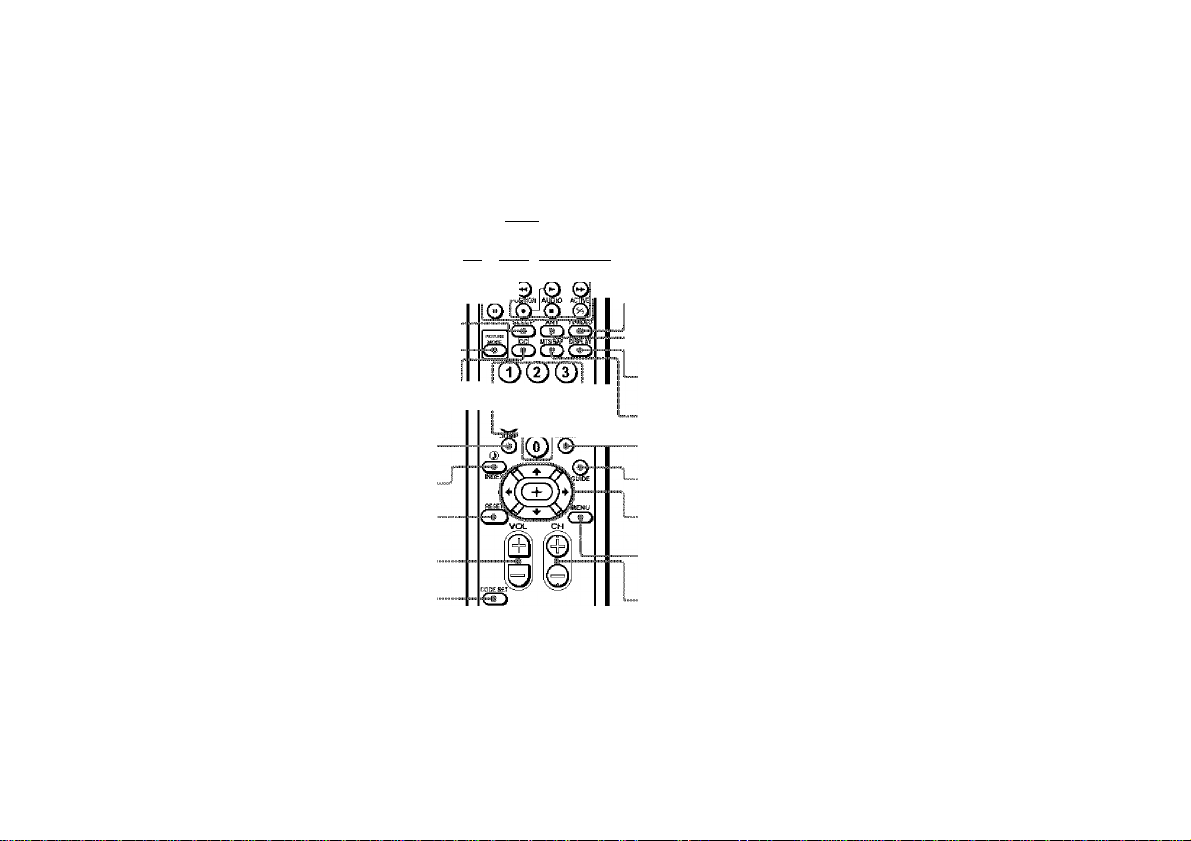
Remote Control
In the instructions that follow, we will MUTING ■
refer to the buttons on your remote control. 20)
Keep this flap unfolded and use this page gygjgjyi Qpp
for reference.
(page 22)
VCR/DVD/MDP
operation buttons
(page 48)
SLEEP (page 22)
PICTURE MODE (pages 20, 26)
[CCjipage 22)
0-9 buttons
(page 20)
JUMP (page 21)
'■.i; (pages 22, 27)/
INDEX (for SAT, page 49)
(pages 23, 26, 27)
RESET
VOL +/- (page 20)
CODE SET
(pages 47, 49)
UUTKGS C№ SBir POW№
y 71R c*ai£ /•'*>.;
©
¡qqQ
Off Й omm SATi'iABtJ ту
•• •iSjczi.a.ci
ГИ
iOir ‘ ‘
i®®®i
SONY
. POWER
(pages 20, 48, 49)
FUNCTION
(pages 20, 48, 49)
PIP operation
buttons
(page 23)
TV/VIDEO
(pages 21, 23)
- ANT (page 24)
DISPLAY
(page 21)
MTS/SAP
(pages 22, 27)
ENTER (page 20)
GUIDE (page 49)
♦/♦/♦/♦ and
buttons
(page 25)
MENU (page 25)
CH +/- (page 20)
Getting to know the buttons on the
remote control
Names of the buttons on the remote control are
presented in different colors to represent the
available functions.
Button color
Transparent .... Press to select the component
you want to control: e.g. VTR
(VCR)/MDP/DVD Player,
SAT (satellite receiver)/
Green
.................
Label color
White
.................
Yellow
................
Blue
....................
Green
.................
Pink
....................
Fora detailed explanation of most buttons, see
“Watching the TV" on page 20.
CABLE, or projection TV.
Buttons relevant to power
operations, like turning the
projection TV, SAT/CABLE, or
VTR (VCR)/MDP/DVD Player
on or off
TV/VTR (VCR)/MDP/DVD
Player/SAT (satellite
receiver)/CABLE operation
buttons
PIP operation buttons
SAT operation buttons
S-Link operation buttons
DVD Player operation buttons
Page 4

m'iabie of Coi^tmts
Wekomel........................................ f
Using Ttm Manual.......................... f
Freoiffloiis.....,,......,.............—,...—, 2
importMM SafeguMrUs....................... J
For Safety
....................................................
6
imMSing ant# Cmmmetmg ffte
Frq^eeiion TV....................... 7
Carrying Your Projection TV
Installing the Projection TV
Connector Types
Making Connections..................................8
Connecting directly to a cable or an
antenna
Cable or antenna..................................9
Cable and antenna...............................9
Connecting a cable box
Cable box and cable
Connecting a cable TV system/
antenna to a VCR
Connecting a VCR and projection TV
to a cable box..................................10
Connecting a satellite receiver (SAT) 12
........................................
.............................................
...................
......................
.......................
............................
..........................
7
7
8
8
9
9
10
Connecting a satellite receiver (SAT)
and a VCR
Connecting a DTV (digital television)
receiver
Connecting a camcorder...................14
Connecting a DVD Player
Connecting a DVD Player with
component video output
connectors
Connecting an audio system............16
Connecting a Sony SAVA series
speaker system
......................................
.........................................
................
......................................
..............................
13
14
15
15
17
msksm. Up................................... w
Using the Remote Control
Setting Up the Projection TV
Automatically
Adjusting the Convergence Automatically
(FLASH FOCUS)
......................
.................................
............................
18
18
19
ilsHig Yimr Pmjestion TV.... 20
Vtetchlng the TV
\fetchlng Two Programs at One Time
...
PIP.................................................23
......................................
20
Aۤmtmg Worn'SET UP imenm}... 25
Learning Menu Selection
B Using the Video Menu.........................26
Using the Audio Menu
© Using the Timer Menu
& Using the Channel Set Up Menu.30
Setting and Selecting Favorite Channel.. 32
& Using the Set Up Menu
Using the Parental Control Feature
Activating the Parental Control
Feature
............................................
Selecting a Custom Rating
in U.S.A...........................................38
Selecting a Custom Rating
in Canada
Changing the Password
What the Ratings Mean...........................43
Ratings in U.S.A.................................43
Ratings In Canada
.......................................
........................
......................
........................
.................
......
...................
.............................
25
27
29
34
36
36
41
42
45
Page 5

Ilf ..refcoinef
Usk'-’ ikisMmuai
Operafing ¥Me€i 47
Setting the Manufacturer's Code
...............
47
OperatMig a SaMe 8qx or Safefiiie
SeceiVer fS^IJ 4f
Setting the Manufacturer's Code
Tmu7Mmi^€mting §0
...............
49
Spmifimtmm................................... 52
ificfe^ 55
Owner's Record
The model and serial numbers are located at the fear of
the pfojection TV, below the Sony logo, on the sticker,
and also on the TV box (white label). Kecord these
numbers in the spaces pfovided below. Refer to them
whenever you call upon your Sony dealer regarding this
product.
Model No. __________________________________________
Serial No.
__________________________________________
Thank you for purchasing the Sony Color
Rear Video Projection TV.
This manual is for models KP-43T90. KP48V90, KP-53V90, KP^61V90.
Model KP-53V90 is used for Illustration
purposes.
The features you will enjoy include:
• FLASH FOCUS, allowing you to adjust
convergence automatically.
• Parental Control, enabling you to block
programs that you feel are unsuitable for
your children.
• Picturedn-Picture (PIP), allowing you to
view another TV channel, video or cable
Image as a window picture.
• Favorite Channel, allowing you to
view and choose from eight of your
favorite channels
• Y/Pb/Ph inputs for DVD Player and DTV
receiver connections.
• Three AUDIO/VIDEO/S VIDEO Inputs.
We recommend that you carefully review
the contents of the following four sections in
the order provided to ensure that you fully
understand the operation of your new
projection TV.
1 InstalWng and Connecting the Projection
1¥
This section guides you through your
initial set up. It shows you how to install
your projection TV, to connect your new
components and to connect to the
antenna and cable.
2 Basic Set Up
This section teaches you the basic skills
needed to operate your new projection
TV. including Auto Set Up. It shows you
how to operate the remote control’s
special functions.
3 Using Your Mem Projection 1¥
This section shows you how to begin
using your new projection TV. It shows
you how to use your remote control’s
features.
4 Adjusting Your Set Op
This section teaches you how to access
on-screen menus and adjust your
projection TV’s settings.
ImiivdJons in this mmal are mitten ftr tls mmte
cor^ivl. Siniilar amimtf may be imind on the prc^iian
TVwrmk.
Page 6

ili Precaiitiom
Safety
• Operate the projection TV only on 120 V
AC.
• The plug Is designed, for safety purposes,
to fit into the wall outlet only one way. If
you are unable to Insert the plug fully
into the outlet, contact your dealer.
• If any liquid or solid object should fall
Inside the cabinet, unplug the projection
TV immediately and have It checked by
qualified service personnel before
operating it further.
• If you will not be using the projection TV
for several days, disconnect the power by
pulling the plug Itself. Never pull on the
cord.
Note on cleaning
Clean the cabinet of the projection TV with a
diy soft cloth. To remove dust from the
screen, wipe it gently with a soft cloth.
Stubborn stains may be removed with a cloth
slightly dampened with solution of mild
soap and warm water. Never use strong
solvents such as thinner or benzine for
cleaning.
If the picture becomes dark after using the
projection TV for a long period of time, it
may be necessary to clean the Inside of the
projection TV. Consult qualified service
personnel.
Installing
• To prevent internal heat buildup, do not
block the ventilation openings.
• Do not install the projection TV in a hot
or humid place, or in a place subject to
excessive dust or mechanical vibration.
• Avoid operating the projection TV at
temperatures below 5" C (41® F).
• If the projection TV is transported
directly from a cold to a warm location,
or if the room temperature changes
suddenly, the picture may be blurred or
show poor color. In this case, please wait
a few hours to let the moisture evaporate
before turning on the projection TV.
• To obtain the best picture, do not expose
the screen to direct illumination or direct
sunlight. It is recommended to use spot
lighting directed down from the celling
or to cover the windows that face the
screen with opaque drapery. It Is
desirable to install the projection TV in a
room where the floor and walls are not of
a reflective material.
Page 7

li' ^ Important Safeguariis
For your protection, please read these
instructions completely, and keep this
manual for future reference.
Carefully observe and comply with all
warnings, cautions and instructions placed
on the set, or described in the operating
Instructions or service manual.
WARNtNG
To guard against injury, the following basic
safety precautions should be observed In the
installation, use, and servicing of the set.
Use
Power Sources
This set should be
operated only from the
type of power source
Indicated on the serial/
model plate.
If you are not sure of the type of electrical
power supplied to your home, consult your
dealer or local power company. For those
sets designed to operate from battery power,
refer to the operating instructions.
Grounding or Polarization
This set is equipped with a polarized AC
power cord plug (a plug having one blade
wider than the other), or with a three-wire
grounding type plug (a plug having a third
pin for grounding).
Follow the Instructions below:
For the set with a
polarized AC power
cord plug
This plug will fit into the power outlet only
one way. This is a safety feature. If you are
unable to Insert the plug fully Into the outlet,
try reversing the plug. If the plug should still
fail to fit, contact your electrician to have a
suitable outlet Installed. Do not defeat the
safety purpose of the polarized plug by
forcing it in.
Alternate Warning
For the set with a
three-wire grounding
type AC plug
This plug will only fit into a grounding-type
power outlet. This is a safety feature. If you
are unable to insert the plug into the outlet,
contact your electrician to have a suitable
outlet installed. Do not defeat the safety
purpose of the grounding plug.
Overloading
Do not overload wall
outlets, extension cords or
convenience receptacles
beyond their capacity,
since this can result in fire
or electric shock.
Always turn the set off
when it is not to be used.
When the set is left
unattended and unused
for long periods of time,
unplug it from the wall
outlet as a precaution
against the possibility of
an Internal malfunction
that could create a fire
hazard.
Ol^oct and Liquid
Entry
Never push objects of any
kind into the set through
the cabinet slots as they
may touch dangerous
voltage points or short out
parts that could result in a
fire or electric shock.
Never spill liquid of any kind on the set.
Attachments
Do not use attachments
not recommended by the
manufacturer, as they may
cause hazards.
(continued)
Page 8

^ ^ riportant Safeguariis (cmttiiweti}
Cleaning
Unplug the set from the
v-vall outlet before
cleaning or polishing It.
Do not use liquid cleaners
or aerosol cleaners. Use a
cloth lightly dampened
with water for cleaning
the exterior of the set.
If a snapping or popping
sound from a projection
TV set Is continuous or
frequent while the
€i
projection TV Is
operating, unplug the
projection TV and consult
your dealer or service
technician.
It Is normal for some projection TV sets to
make occasional snapping or popping
sounds, particularly when being turned on or
off.
Installation
Water and Moisture
Do not use powerdine
operated sets near
water
...
a bathtub, washbowl,
kitchen sink, or laundry
tub, in a wet basement or
near a swimming pool,
etc.
for example, near
Use only a cart or stand recommended by the
manufacturer for the specific model of
projection TV.
Ventilation
The slots and openings In the cabinet and In
the back or bottom are provided for
necessary ventilation. To ensure reliable
operation of the set. and to protect It from
overheating, these slots and openings must
never be blocked or covered.
Acc^sories
Do not place the set on an
unstable cart, stand, table
or shelf. The set may fall,
causing serious injury to a
child or an adult, and
serious damage to the set.
An appliance and cart
combination should be
moved with care. Quick
stops, excessive force, and
uneven surfaces may
cause the appliance and
cart combination to
overturn.
- Never cover the slots
and openings with a
cloth or other materials.
- Never block the slots and
openings by placing the set
on a bed, sofa, rug or other
similar surface.
- Never place the set in a
confined space, such as a
bookcase, or built-in
cabinet unless proper
ventilation Is provided.
- Do not place the set near
or over a radiator or heat
register, or where it Is
exposed to direct sunlight.
Power-Cord Protection
Do not allow anything to
rest on or roll over the
power cord, and do not
place the set where the
power cord Is subject to
wear or abuse.
Page 9

Antennas
Outdoor Antenna Grounding....If an
outdoor antenna Is Installed, follow the
precautions below.
An outdoor antenna system should not be
located in the vicinity of overhead power
lines or other electric light or power circuits,
or where it can come In contact with such
power lines or circuits.
WHEN INSTALLING AN OUTDOOR
ANTENNA SYSTEM, EXTREME CARE
SHOULD BE TAKEN TO KEEP FROM
CONTACTING SUCH POWER LINES OR
CIRCUITS AS CONTACT WITH THEM IS
ALMOST INVARIABLY EATAL.
Be sure the antenna system is grounded so as
to provide some protection against voltage
surges and built-up static charges.
Section 810 of the National Electrical Code
(NEC) in USA and Section 54 of the
Canadian Electrical Code in Canada provides
information with respect to proper
grounding of the mast and supporting
structure, grounding of the lead-in wire to an
antenna discharge unit, size of grounding
conductors, location of antenna discharge
unit, connection to grounding electrodes, and
requirements for the grounding electrode.
Antenna Grounding According to the
NEC
....
Refer to section 54-300 of Canadian
Electrical Code for Antenna Grounding.
Antwnna iead-in
Ground damps
. hat-'j'.
■ •■ 1 ^ iiri
' .I'/Un.iiUKj
t', r, fSrC
inO d-Silip
equipment
SEE Sationa!
Efectrfca! Cod»
;ir+ ii'ri'i 1 H*
Lightning
For added protection for this television
receiver during a lightning storm, or when It
is left unattended and unused for long periods
of time, unplug it from the wall outlet and
disconnect the antenna. This will prevent
damage to the receiver due to lightning and
power-ilne surges.
Service
Damage Requiring Service
Unplug the set from the wall outlet and refer
servicing to qualified service personnel under
the following conditions:
C/?Aci'Si> pi-1*
- When the power cord or
plug is damaged or
frayed.
- If liquid has been spilled
Into the set.
- If the set has been
exposed to rain or water.
- If the set has been
subject to excessive shock
by being dropped, or the
cabinet has been
damaged.
Page 10

iii mportant Safèguarés (cmtiimeé)
- If the set does not
operate normally when
following the operating
Instructions. Adjust only
those controls that are
specified In the operating
Instructions.
Improper adjustment of
other controls may result
In damage and will often
require extensive work by
a qualified technician to
restore the set to normal
operation.
- When the set exhibits a distinct change in
performance
service.
...
this indicates a need for
Servicing
Do not attempt to service
the set yourself since
opening the cabinet may
expose you to dangerous
voltage or other hazards.
Refer all servicing to
qualified service
personnel.
Replacement Parts
When replacement parts are required, be
sure the service technician certifies in writing
that he has used replacement parts specified
by the manufacturer that have the same
characteristics as the original parts.
Unauthorized substitutions may result in
fire, electric shock, or other hazards.
Safety Check
fTVSBKVICEDErT.
Upon completion of any
service or repairs to the
set, ask the service
technician to perform
routine safety checks (as
specified by the
manufacturer) to
determine that the set Is
in safe operating
condition, and to so
certify.
When the set reaches the
end of its useful life,
improper disposal could
result in a picture tube
implosion. Ask a
qualified service
technician to dispose of
the set.
For Safety
Be careful when moving the projection TV
When you place the
projection TV in
position, be careful not
to drop it on your foot or fingers.
Watch your footing while installing the
projection TV.
Carry the projection
TV in the specified
manner
If you cany the
projection TV in a
manner other than the
specified manner and without the specified
number of persons, It may drop and a serious
Injury may be caused. Be sure to follow the
instructions mentioned below.
- Carry the projection TV with the specified
number of persons.
- Do not carry the projection TV holding the
speaker grill.
- Hold the projection TV tightly when
carrying it.
Page 11

M ^ /istaHmg afitf Conmetmg the Projection T¥
Carrying Your Projection TV Installing the Projection TV
Carrying the projection TV requires three or
more people.
For KP-48V90/S3V90/61V90
The projection TV has been equipped with
casters for easy movement on a hard surface.
Please move your projection TV using the
casters.
Recommended viewing area
(Vertical)
Page 12

•f ImtaUing anti Connect«K¡ tiv. fayection TV (continued)
Connector Types
You may find it necessary to use some of the
following connector types during set up.
Coaxial cable
Standard TV cable and antenna cable
Plug Type
Screw-on Type
S Video cable
High quality video cable for enhanced
picture quality
AudfoA/ideo cable
Some DVD Players and DTV Receivers are
equipped with the following three video
connectors.
„ Ph (Cr. Cr or R
___
^
№
Video - Yellow
Audio (Left) - White
Audio (Right) - Red
Y - Green
Pb(Cb, CborB.Y)-Blue
...
Y)-Red
Push into connection ^Lbocit the CI^NTRCJL S CJUT jack
Screw into connection.
push into connection.
Push into connection.
CONTROL S cable
Sony cable for CONTROL S connection. This
feature is exclusive to Sony products and
allow greater control of all Sony equipment.
i|D
Push into connection.
To control other Sony equipment with the
projection TV’s remote control, connect the
CONTROL S IN Jack of the equipment to the
CONTROL S OUT jack on the projection TV
with the CONTROL S cable.
Making Connections
Connecting directly to a cable or an antenna
The connection you choose will depend on
the cable found in your home. Newer homes
will be equipped with standard coaxial cable
(see A): older homes will probably have 300ohm twin lead cable (see B); still other
homes may contain both (see C).
Use 75-ohm coaxial cable for Improved
picture quality (see A).
fR®sf of
prejwtion
VHF/UHF
WS 3
'hill
L'
• VHF only
• VHFfUHF
• Cable
B
■ VHF only
' UHFonly
' VHFÍUHF
or
or
or
or
'iS-otim
eoaiia! csWe
Page 13

'iS'Olini ioatla! cable
VHF
{Rear of
prsj|eetion TV|
VHF/yHF
and
EAC-S6 U№ miwr
{noi i5Bppl̫J)
UHF
39O"0hm twin featl Mbte
Cable or antenna
This is the simplest connection. Connection is
made directly from the cable or antenna to
the projection TV.
{Rear ef propctiors T¥|
Cable and antenna
You may find it convenient to use the
following set up if your cable provider does
not feature local channels that you are able to
receive using an antenna.
ih.-; r -jr ;jiiwi' TV) Cable box and cable
CoaKial satsie
|Ho Wfinestiorj "TO R-T">r: 'in:TEl
COHVEKTER" in this Sn'.»*; tlfl
Antenna cable '“ill‘unr
Select Cable or ANT mode by pressing ANT
on the remote control.
AOS,
.'ill
ill
Connecting a cable box
Some pay cable TV systems use scrambled or
encoded signals that require a cable box* to
view all channels.
Also, set “Cable” to “On” In the Channel Set
Up menu (page 31).
|Eear csf projwiion TV)
Coaxial sable ¥HF/UHf
^=03
.................
IM OUT
*Cabte bsf
iSlI
Some pay cable TV systems use scrambled or
encoded signals requiring a cable box* only for
certain channels (e.g. HBO, SHOWTIME, etc.)
'■ Cable bos
Ssramtiiiiii
chinne^
{ynarambled «ti»nnsls|
..
a:^=a3
fi „‘li
CA I'k Cl'II»:•
iJ/'ir.'i ‘¡.Sii Tl“]
=03 .'GS
(,i,= .'ii>‘,U.-l '-rtbR
<13 G®
r; v.';i i-ink lies
■ c®
t
itii-Ji'-i!'
T-i;-
For this set up, you can switch between
scrambled channels (through your cable
box), and normal (CATV) channels by
pressing ANT on your remote control.
Notes:
• You may be able to program your Sony
remote control to operate your cable box.
(see “Operating a Cable Box or Satellite
Receiver (SAT)” on page 49)
• During PIP or Favorite Channel viewing,
the AUX Input can only be viewed in the
main picture.
• AUX Input cannot be viewed In the PIP
windows. g
Page 14
•f htstaUing and Connect«n-liv. fayection T¥ (continued)
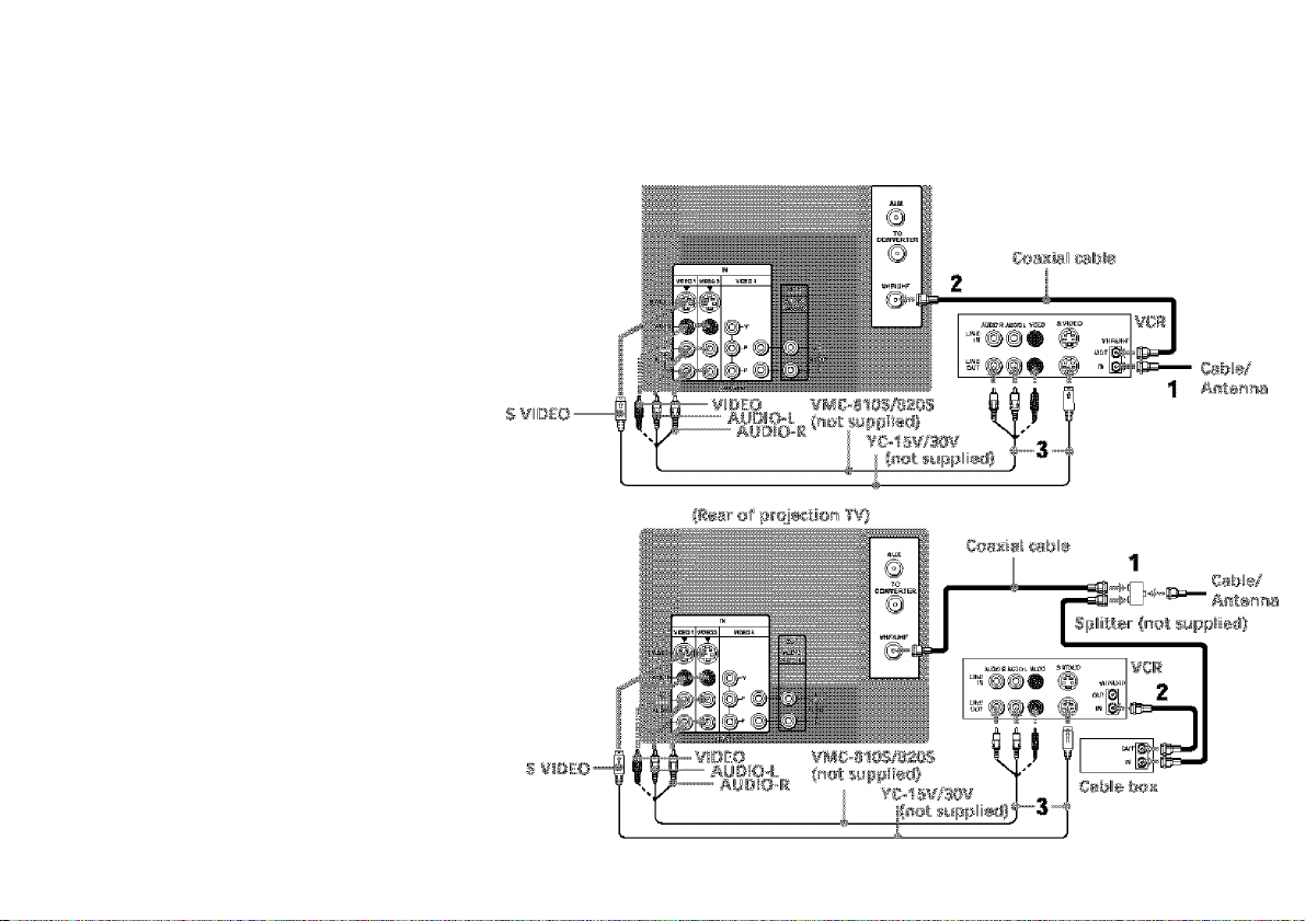
Connecting a cable TV systenV antenna to a VCR
1 Attach the coaxial cable from the
Incoming cable connection or antenna to
VHF/UHF IN on the VCR.
2 Using a coaxial cable, connect VHF/UHF
OUT on the VCR to VHF/UHF on the
projection TV.
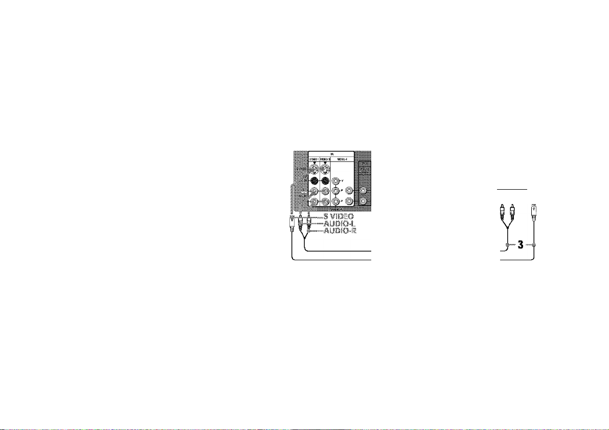
3 Using AUDIO and S VIDEO* cables,
connect AUDIO and S VIDEO OUT on the
VCR to AUDIO and S VIDEO IN on the
projection TV iWhlte-AUDIO Left, RedAUDIO Right”).
Connecting a VCR and projection
TV to a cable box
1 Connect the single (Input) jack of the
splitter to the Incoming cable connection,
and connect the other two (output) jacks
(using the coaxial cable) to IN on the cable
box and VHF/UHF on the projection TV.
2 Using a coaxial cable, connect OUT on the
cable box to VHF/UHF IN on the VCR.
3 Using AUDIO and S VIDEO* cables,
connect AUDIO and S VIDEO OUT on the
VCR to AUDIO and S VIDEO IN on the
projection TV (White-AUDIO Left, RedAUDIO Right**).
1i ®
Disconnect all power sources before making any connections.
pi»r of projection T¥J
Page 15

Note:
• To view scrambled channels through the
cable box, select the video Input which the
cable box Is connected to by pressing TV/
VIDEO.
* If your VCR is not equipped with S VIDEO, use
a VIDEO cable (yellow) instead of the S VIDEO
cable,
** If you are connecting a monaural VCR, connect
only the single audio output to flic left (MONO)
input on the projection TV.
11
Page 16
•f ImtaUing anti Connecting the Projectiof! ry (continuea)
Connecting a satellite receiver
(SAT)
1 Connect the cable from the satellite
antenna to the satellite receiver.
2 Attach the coaxial cable from the incoming
cable connection or antenna to VHF/UHF
on the projection TV.
3 Using AUDIO and S VIDEO cables,
connect AUDIO and S VIDEO OUT on the
satellite receiver to AUDIO and S VIDEO
IN on the projection TV (White-AUDIO
Left, Red-AUDIO Right).
Note:
• To view input from the satellite receiver,
select the video input which the satellite
receiver Is connected to by pressing TV/
VIDEO on the remote control.
Disconnect all power sources before making any connections.
pear ciif pi-'opciion T¥|
BK-Ï4II inol supplied)
¥C-1S¥/30¥ Cost supplieit
Cable/
AntBriina
Satellite antenna
I safe!«
1
SAT
JsiOhat; MiML w
1
12
Page 17
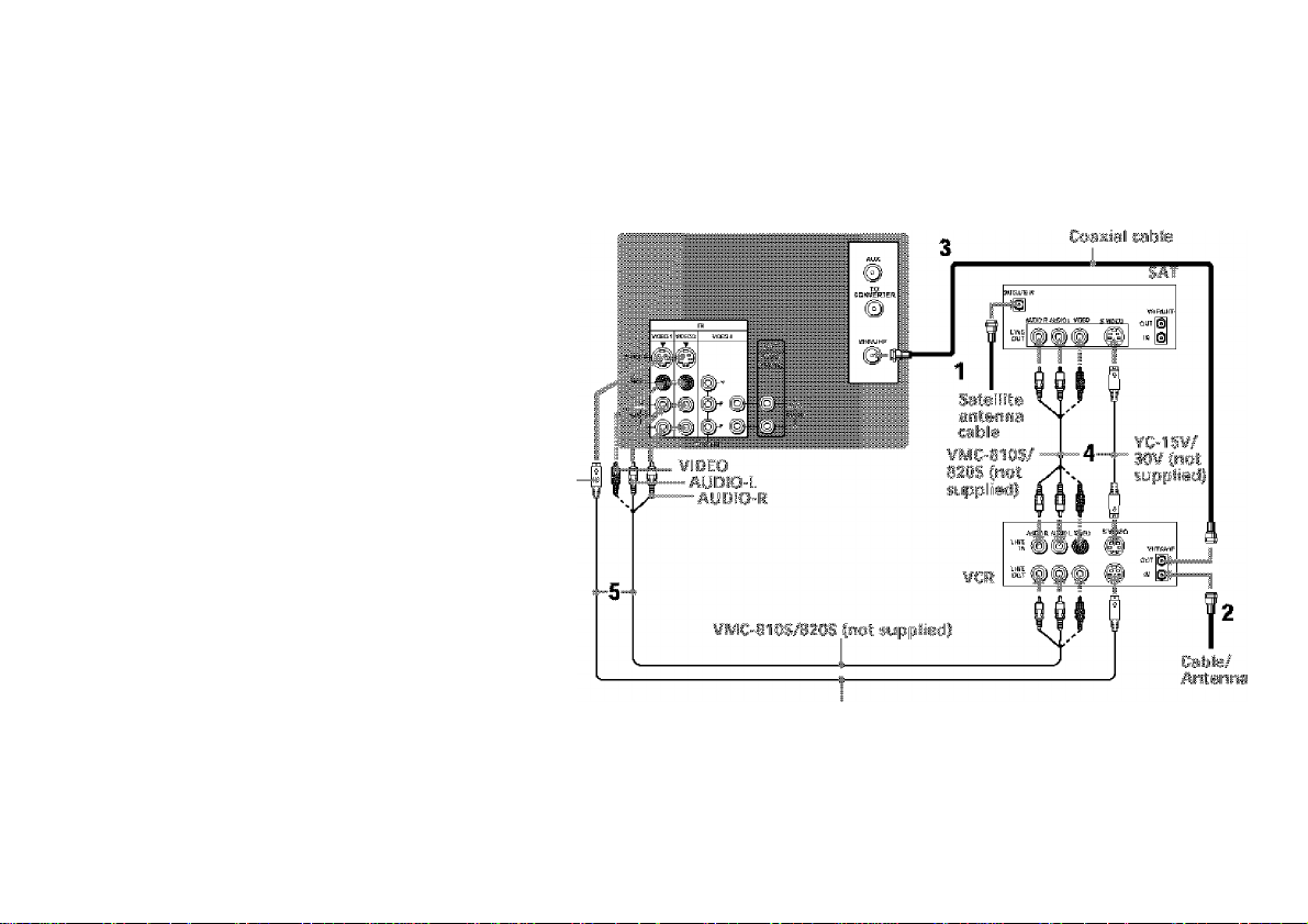
Connecting a satellite receiver
(SAT) and a VCR
1 Connect the cable from the satellite
antenna to the satellite receiver,
2 Attach the coaxial cable from the
incoming cable connection or antenna to
VHF/UHF IN on the VCR.
3 Using a coaxial cable, connect VHF/UHF
OUT on the VCR to VHF/UHF on the
projection TV.
4 Using AUDIO and S VIDEO* cables,
connect AUDIO and S VIDEO OUT on the
satellite receiver to AUDIO and S VIDEO
IN on the VCR.
5 Using AUDIO and S VIDEO* cables,
connect AUDIO and S VIDEO OUT on the
VCR to AUDIO and S VIDEO IN on the
projection TV (White-AUDIO Left, RedAUDIO Right).
*If your VCRis not equipped with S VIDEO, use a
VIDEO cable (yellosv) instead of the S VIDEO
cable.
Note:
• To view input from the satellite receiver or
VCR, select the video input which your
satellite receiver or VCR is connected to
by pressing TV/VIDEO on the remote
control.
Disconnect aff power sources before making any connections.
{Rear of projKtisn T¥|
S ¥lBEO
¥C-1S¥/30¥ Cost supplied!
13
Page 18

M ^ ImtaUing and Connecting the Projecti ontinued)
_ - - Disconnect all power sources before nmking any connections.
Connecting a DTV (digital television) r^eiver ^ ^
Before connecting, be sure to read the Operating
Instructions of the DTV receiver.
1 Attach the coaxial cable from the roof
antenna to VHF/UHF IN (DTV) on the DTV
receiver.
2 Using AUDIO and S VIDEO cables, connect
AUDIO and S VIDEO OUT on the DTV
receiver to AUDIO and S VIDEO IN on the
projection TV (White-AUDIO Left, RedAUDIO Right).
Notes:
• Your DTV receiver must be able to support
4801 video format output.
• If your DTV receiver supports 4801 signal
from YPbPh, you can connect Y, Pb and Ph of
VIDEO OUT on the DTV receiver to Y, Pb
and Pr of VIDEO 4 IN on the projection TV
using VIDEO cables.
Connecting a camcorder
Use this connection to view a picture directly
from your camcorder.
1 Using AUDIO and S VIDEO* cables, connect
AUD!o and S VIDEO OUT on the camcorder
to AUDIO and S VIDEO IN Inside the drop
down panel on the front of the projection TV
(White-AUDIO Left, Red-AUDIO Right**).
2 Press VIDEO 2 to select the video Inputs
from a camcorder.
• ir your camcorder is not equipped with S VIDEO,
use a VIDEO cable (yelkmj instead of the S VIDEO
cable,
** If you are connecting a monaural camcorder,
connect only the single audio output to the left
(MONO) input on the projection TV.
14
S ViOEO
{Rear of proieetion TV)
m
KK-
YC-lS¥/3li¥ fnsl »uppli^iii
BT¥ resesver
Koof antersiia
jpliedl
¥C"15¥/3{}¥ fsiol aippliedi
□
Page 19

Connecting a DVD Player (Upper illustration)
Using an AUDIO and S VIDEO cables,
connect AUDIO and S VIDEO IN on the
projection TV to AUDIO and S VIDEO OUT
on the DVD Player (White-AUDIO Left, Red-
AUDIO Right).
Connecting a DVD Player with
CK>mponent video output
connectors (Lower illustration)
1 Using an AUDIO cable, connect AUDIO of
LINE OUT on tlie DVD Player to AUDIO of
VIDEO 4 IN on the projection TV (WhiteAUDIO Left, Red-AUDIO Right).
2 Using three yellow VIDEO cables, connect
Y, Pa, and Piiof COMPONENT VIDEO
OUT on the DVD Player to Y, Pb. and Pr of
VIDEO 4 IN on the projection TV.
Notes:
• Since die high quality pictures an a DVD
disc contain a lot of information, picture
noise may appear. In diis case, adjust "Noise
Reduction” in the Video menu, (see "Noise
Reduction” on page 2fi)
• Some DVD Player terminals may be labeled
differently. If so. connect as follows;
Connect Y (green) to Y,
Connect Pb (blue) to Cb. Cb or B-Y,
Connect Pr (red) to Ch, Cr or R-Y.
• This projection TV <loes not support
progressive scan DVD players output, Please
use the interlaced output,
Disconnect all fx>wer sources before making any connections.
Page 20

•f ¡mtalling and Connect«n-liv. fayection T¥ {continued)
Connecting an audio system
For more dynamic sound, connect an audio
system to the projection TV.
1 Using an AUDIO cable, connect AUDIO
(VAR/FIX) OUT on the projection TV to
one of the unused Line Inputs (e.g. Tape2, AUXl, etc.) on the stereo.
2 Set the stereo to the chosen Line Input
and use the Audio menu to set the audio
output and switch the TV’s speakers off.
(see “Audio Out’ and “Speaker” on page
28)
Note:
• You can adjust VOLUME. "Bass,”
“Treble,” “Balance,” “MTS/SAP” and
“Effect” with the supplied remote control.
The control Items except VOLUME can be
adjusted only when “Audio Out” Is set to
“Variable” In the Audio menu, (see
“Audio Out” on page 28)
{Ii©lir of prqjsclion T¥|
Disconnect alt power sources before making any connections.
Starwo aimpiitiar
@
I
AUDfO-l.
(wsrliitsi)
AUOiO-R
iradj
©
etC-MA
{not SUppliKi)
----------------------
1
Line inputs
1i
Page 21

Connecting a Sony SAVA series speaker system
Use this connection to control the speaker’s
Dolby* Pro Logic surround system and
super woofer mode with the remote control,
(see “SAVA SP Control’ on page 28)
1 Using the AUDIO cable supplied with the
speaker to AUDIO (VAR/FIX) OUT on
the projection TV.
2 Using the CONTROL S cable, connect
CONTROL S IN on the speaker to
CONTROL S OUT on the projection TV.
’ Manufactured under license from Dolby
Laboratorie.s.
“Dolby”, “Pro Logic”, and the double-D symbol
are trademarks of Dolby Laboratories.
Confidential unpublished works. ©1902-1997
Dolby Laboratories. All rights reserved.
coat"
OUT
Disconnect all power sources before making any connections.
CR©ir of prqjitclion T¥|
j34, et®, {not supplii
1 № i
IK H
iludiiij cor'd siippliiti
with ths »peatere
COHTKOlSIM
SAìià. series
speaker sysitem
o o
w
1?
Page 22

Using the Remote Control
Inserting the batteries
Insert two size AA (R6) batteries (supplied)
by matching the + and
the diagram Inside the remote control’s
battery compartment.
Notes:
• Remove the batteries to avoid damage
from possible battery leakage whenever
you anticipate that the remote control
will not be used for an extended period.
• Handle the remote control with care.
Avoid dropping it, getting it wet, or
placing it in direct sunlight, near a heater
or where the humidity is high.
• Your remote control can be programmed to
operate most video equipment.
(see “Operating Video Equipment” on
page 47)
...
on the batteries to
Setting Up the Projection TV Automatically
The AUTO SET UP feature will allow you to
set the on-screen language and set all
receivable channels.
The AUTO SET UP feature does not apply for
installatiom that use a cable box for all channel
selection.
You can also set up the projection TV manually,
(see “Using the Channel Set Up menu" on pages
30 and 31)
Notes:
• Before you perform AUTO SET UP again,
make sure that the input from ANT (not
AUX) is selected by pressing ANT until
“ AUX" does not appear next to the
channel number.
• Perform this function during the day, with
the antenna and/or cable properly
connected, to ensure that all available
channels will be broadcasting and
receivable.
• When you perform AUTO SET UP, all the
settings In the Video, and Audio menus
are reset to the factory settings.
Using the buttons on the front panel of the
projection TV:
janFCísaTsííVIDEC "• VOUIME + “ CHANNEL + POWffiR TSffisrassBf
□ D D D D D Û “
1 Press POWER to turn on the protection
TV.
Press SET UP inside the drop-down panel
on the projection TV and the AUTO SET
UP screen appears.
POWER
Press CHANNEL + to select English,
CHANNEL.. to select Español or
VOLUME + to select Français.
The screen will change to reflect your
choice.
- VOLUME + — CHANNEL +
D D D 0
Engfisb :
Esupnpt ;
Français :
A(Jt.Q Silt up :
First piease ccnrrftts;
fhEi sntenna-
WHiW g sur UP] tüsxib
Entjiisb :
Esppbot :
Fiarigais :
Aillo Sili Up ;
Prim&iü rariíícái i±i
arrtena.
ÜpiÎTîiH [SETUP) paiB
salir.
IVOL*|
[vai-5
[CH 'i-i
ICH-Ï
[VOL'i-5
[VOL-Ì
Page 23

Press VOLUME
— VOLUME +
...
to continue.
Uurrt.inius
Auto Prograni ?
V6& :
Nw . ?CH-I
Press CHANNEL + to preset channels
automatically.
‘ CHANNEL+
To perform AUTO SET UP again
• o o o o
SETUP MENU
HJ«K Fcaa TVJVI DH>
a D
3
Press SET UP Inside the drop-down panel on
the projection TV and perform steps 2-4
above.
Press SET UP again to exit.
“Auto Program" appears and the
projection TV starts scanning and
presetting channels automatically. While
scanning, the received channel will be
displayed on the sub screen. When all the
receivable channels are stored, the lowest
numbered channel Is displayed.
Adjusting the Convergence Automatically (FLASH FOCUS)
The projection tube Image appears on the
screen In three layers (red, green and blue). If
they do not converge, the color Is poor and
the picture blurs.
Before you use your projection TV, be sure to
adjust the convergence.
The FLASH FOCUS feature allows you to
adjust the convergence automatically.
Tips
• It is recommended to perfonn FLASH FOCUS about
30 minutes after the projection TV is first turned on.
• You can also peribrin FLASH FOCUS using the Set
Up menu on page 35,
The cross pattern appears and FLASH
FOCUS begins to work. The adjustment Is
completed when the cross pattern becomes
white.
Note:
• FLASH FOCUS Is canceled if you
perform any other function while FLASH
FOCUS Is working.
Page 24

Usmg Ymr 1 /., /' , / ’
Watching the TV
Many TV features can be accessed directly
through the reniote control. The following
chart will explain the function of some
buttons found on your remote control.
TV (FUNCTION)
TV POWER
and ENTER
CH +/-
VOL +/-
MUTING
m
Activates the remote control for use with the projection TV.
Turns the projection TV on and off. If a video input indication (e,g., VIDEO 1,
VIDEO 2) appears on the screen, press TVA/IDEO until a channel number
appears.
Use for direct channel selection. Press 0-3 to select a channel (for example,
to select channel 10, press 1 and 0). The channel will change after 2
seconds, or you can press ENTER for immediate selection.
Press to scan through the channels {+ up or - down).
Spe0d Surf
1 Press and hold CH + or-to change the channel number rapidly.
2 Release to display the desired channel.
Press to adjust the volume {+ up or - down).
Press to mute the sound, “Muting" will appear on the screen and will dim
three seconds later. To restore sound, press again or press VOL +.
PICTURE MODE
Press PICTURE MODE repeatedly to directly
choose one of five different video modes that
best suits the program you are watching.
Vivid: Select for enhanced picture contrast and
sharpness.
Standard: Select to display a standard
picture for normal viewing environments.
Movie: Select to display a finely detailed
picture for low light environments.
Personal 1, Personal 2: Select to customize
the “Picture Adjustmenf of the Video menu
according to your personal preference.
When you select “Vivid" and “Standard," all
video control settings are fixed.
When you select “Movie," “Personal 1" and
“Persona! 2,“ you can also perform the “Picture
Adjustmenf {such as “Brightness," “Color," etc.)
to suit your taste. For details, see “Mode" on
page 26.
Page 25

U y I L ]l i 1 Buliu lo P Oj 1.1 1 Tv 0|j I t n 1
TVA/IDEO
Press repeatedly to scroll through available video inputs:
TV, VIDEO 1, VIDEO 2, VIDEO 3 and VIDEO 4.
If you select “Skip" as a “Video Label" In the Set Up menu, your projection
TV will skip the video input you seiected. (see “Video Label" on page 35)
REFER TO THE
ILLUSTRATION OF THE
REMOTE CONTROL ON THE
INSIDE FRONT COVER OF
THIS MANUAL AS YOU
REVIEW THIS CHART
JUMP
FREEZE
(ysSfjw íaéefecí
biiticm}
DISPLAY
Press to alternate or jump back and forth between two channels. The
projection TV will jump between the current channel and the last channel
selected using the 0-9 buttons.
This is useful when you need to copy down information that appears on the
TV’s screen.
Press to freeze the desired picture. The frozen picture is displayed in the
window picture while viewing the normal picture of the current channel in the
main picture.
Mormal mcstion
pietpi’e
Frozen picture
To change the location of the window picture, press +, * or+.
Press FREEZE again to display the normal picture.
Press to display the channel number, current time, channel caption (if set),
and MTS/SAP mode (if SAP is selected). The SAP indication disappears and
the other indications dim three seconds later.
To turn the display off, press DISPLAY again.
(continued)
t1
Page 26

il^f Using ¥oar Nem Prqeci ^ i(contmueU)
U iiK] IM Wim LiL) I dBiiUcii Ici PrOjCLliun Tv Op i ilinn
[cc]
SLEEP
ANT
(AUX. iiipui)
MTS/SAP
®
TVA/TR
Press repeatedly to scroll through available displays;
XDS (Extended Date Service)
Displays a network name, program name, program type, program length,
program description, call letters and time of the show If the broadcaster
offers this service.
Caption Vision
Displayed on the screen if the broadcaster offers this service, (see
“Caption Vision" on page 34)
No display
“Off* appears and the display is canceled.
Press repeatedly until the projection TV displays the approximate time in
minutes (30. 60, or 90) that you want the projection TV to remain on before
shutting off automatically.
Cancel by pressing until "Sleep Off' appears.
Press to change between the VHF/UHF Input and the AUX input, (for
detailed connection information, see "Cable and antenna" or “Cable box and
cable" on page 9)
Note: You cannot view this input in PIP mode.
Press to scroll through the Multi-channel TV Sound (MTS) options:
Stereo, SAP, Morro and Auto SAP. (see “MTS/SAP" on page 27)
Press to select an audio option;
Simulated, Surround, BBE and Effect Off. (see "Effect" on page 27)
Press when you are finished using a VCR and you want to switch to the TV
input. The VCR power will remain on.
REFER TO THE
ILLUSTRATION OF THE
REMOTE CONTROL ON THE
INSIDE FRONT CO VER OF
THIS MANUAL AS YOU
REVIEW THIS CHART
SYSTEM OFF
Press to turn off the projection TV and all other Sony equipment.
Page 27

Watchinq Two Proqrams at One Time — PIP
The Plcture-ln-Plcture (PIP) feature allows
you to view two channels simultaneously,
one In the full size “main” picture and one In
a smaller “window" picture.
You can move the window picture to any
location on the screen. (Free Layout PictureIn Picture)
The «iymtsoi or *+“
intiiCiles whish preture's
T¥ channei csr input
sourca «Г! be clhanged.
The symija!
irislisates which
piet«re=s sound is being
reeei¥»il.
T¥ shetinei or inputsotH'se mode tor the
■ mairj pietiire® ^eSSo«'-
greeifl~golof®ii}
T¥ than»! or input-
soiu't® motlis for the
leititlo* picture®
{white-coloredi
POSITION
PIP
0
0
ACTIVE
0
Press to display a window picture.
Each time you press this button, the picture size will change
(1/9 —*1/16 —*no display).
To close the window picture, press PIP repeatedly until it disappears.
Press POSITION repeatedly to change the location of the window picture
(counterclockwise) around the main picture.
You can also change the location by pressing the *, +, + or+ button.
The window picture moves in the direction of the arrow indicated on the
pressed button.
Press to select either the main or window picture in order to change the
TV channel or video source using the white labeled buttons below. The
symbol (or “+") will appear to indicate which picture’s channel or input
mode can be changed.
• It will dim in about 3 seconds;
Notes:
• The aux antenna input on the rear panel
will not be able to be selected In the PIP
window.
• If you use a cable box connection, you
will not be able to watch two different
programs at the same time.
TV/VIDEO
Q
isteimJ
ШШ)
Press repeatedly to scroll through the available video inputs for the
picture on which the symbol ‘V (or “+”) is displayed, (see “TV/VIDEO” on
page 21)
lip#
ffyou press RESET in PIP mock, the window picture will mow to the bottom right (factory-preset
location).
23
Page 28

Usmg Your Mem Pmjeetimi T¥ fc0#if#fiuetf|
^ ^ JUMP
or (0)-(9) or O
and ENTER
(mPMe isdeiisd tmiton)
ANT
Q
(mhite- isteimJ
btMfm)
AUDIO
0
FREEZE
0
SWAP
0
U I KJ ih Y lir> i L Itl d Bull 1 to PiP Op ni o iS
Press to select the TV channel on which the symbol ‘V is
displayed, (for details, see “Watching the TV' on page 20)
Speed Surf
1 Press and hold CH + or - to change the channel number rapidly.
2 Release to display the desired channel.
Press to change between the VHF/UHF input and the AUX input for the picture on
which the symboi (or “V) is displayed.
Press to alternate sound between the main picture and the window picture. The
symbol “ji” will appear for a few seconds to indicate which picture’s sound is being
received.
This is useful when you need to copy down information of the main picture.
Press to freeze the desired scene in the main picture. The frozen picture is displayed
in the window picture while viewing the normal picture in the main picture. The
window picture size is automatically changed to 1/9 if it was 1/16,
Press again to resume normal PIP viewing.
Press to switch the audio and video of the main picture and the window picture.
Each time you press SWAP, the picture and sound of the two will be exchanged.
REFER TO THE
ILLUSTRATION OF THE
REMOTE CONTROL ON THE
INSIDE FRONT COVER OF
THIS MANUAL AS YOU
REVIEW THIS CHART
Note:
If one of the pictures received through
PIP is snowy, the entire screen may
become unstable. In this case, erase the
snowy channel, (see "Channel Skip/
Add" on page 31)
m
Page 29

Jif A£§iistmg Voiji ' ; ' imms)
Learning Menu Selection
Use the MENU button to access a menu and
use the +,+,•*',■ ► and GD buttons to alter the
settings. Use the following example to learn
how to modify settings.
1 Press the MENU button.
The main menu appears.
0: Vivid
AdJUStrriftnt
MENU
2 Press + or to highlight the desired menu
and press (GU to activate it.
You may also press 4- to activate your
selection.
üalür TürTi(u ünai
M0ÍK<f ríESCfliCHtin; Off
Movfl »* SgiKá g P'nri NEffj
Kat Up
eg
Caption '
J
O
a
BíM. Niíw
lanfluagi r<j
Video La
H
.............
Fis&h Pu
ufi: Mt)
D
Snlñíde End SEÑ¡3
^ 3
Press + or + to highlight the desired
option.
Press QD.
Options for your selection (Pop-up menu
or Adjusting menu) will be displayed.
Pop"Up meny
Set. Up
f'iirontgi apnlro
CapHnn VÍ.S'
Video Lab
iy-K
AíiiBtirsg menu
' VIDEO?: \
S Press + or + to make your selection and
press GD to activate It.
The previous screen will reappear.
E?Ki !
IÜL01
IDEO?
lÜLOa
IDL04
Some adjustment menus may require
further operations. For details, see each
menu option.
To return to the previous screen (except
for the slider adjustment menus), choose
at the bottom of the menu and press
m or
Once you have completed all menu
corrections, press MENU to exit the menu
screens. ,
MENU
To exit from the menus at any
time
Press MENU.
lip#
You can aho nse ifee MENU, and buttons
inside the front drop-down panel of the projection TV
for the menu selection. gg
Page 30

Jif A£§iistmg Voiji ' ; ' imms) (contmueti)
B Using the Video Menu
vid aa
Model
V i 01 ! rfs ^ :
e
U
g
0
I» SBlect
For detailed information on using the remote
control to modify menu settings, refer to
“Learning Menu Selection” on page 25.
To select the Video B menu:
Disptey Highiight B Select
MENU
To restore the factory settings
Press RESET on the remote control while the
Video menu is selected. To restore each
"Mode” to the factory setting, press RESET
after selecting the mode to be reset.
Note:
“Picture Adjustment,“ “Color Temp“ and
“Noise Reduction" can only be changed In
“Movie,“ “Personal 1“ and “Personal 2“.
2S
Viviij
t ns ^ fi 1;
on ;&ff
Mode You can choose one of live different video modes that best suits the program you
Cusfefflii!®# are watching. You can also perform the “Picture Adjustment" {such as
liialzm “Brightness," “Color,” etc.) for “Movie," “Personal 1” or “Personal 2" to suit your
taste.
Vivid: Select for enhanced picture contrast and sharpness.
Standard; Select to display a standard picture for normal viewing
environments.
Movie: Select to display a finely detailed picture for low light environments.
Personal 1, Personal 2: Select to customize the “Picture Adjustment” of the
Video menu according to your personal preference.
Press PICTURE MODE on the remote control for direct selection of a "Modd'
setting.
Picture First select “Movie,” “Personal 1" or “Personal 2” from “Mode," then highlight the
Adjustment desired option using the ♦ or button and press GD to display the adjusting
Piciiiiv slider of the selected option.
Picture; Adjust slider right (up) to increase picture
contrast; left (down) to decrease it.
Brightness; Adjust slider right (up) to brighten the
Picture !
Co I Of i
picture; left (down) to darken it.
Color: Adjust slider right (up) to increase color
intensity: left (down) to decrease it
Hue; Adjust slider right (up) to increase the green
Mpy№ I» SBIfldt« tnú
tones; left (down) to increase the red tones.
Sharpness: Adjust slider right (up) to sharpen the
picture; left (down) to soften it.
Color Temp Cool: Select to give the white colors a blueish tint.
White mtemitif Neutral: Select to give the white colors a neutral tint.
aiJjimtmml: Warm: Select to give the white colors a reddish tint.
Noise Reduction Select On to reduce picture noise.
Noise m-diioiKxi Select Off to cancel the featu re.
“Noise Reduction’ can be set separatety from the “Mode’ settings of the Video
menu.
Page 31

Using the Audio Menu
Audio
m
Trsbie
Bass
H
Baiartcö
MTS/5AP;
©
Steady Sound: On
Effect: Surrou nd
a
Speaker: On
o
Audio Oui : Variable
SAVA SP
13
Move •• Sated e End BIJ
Control
For detailed information on using the remote
control to modify menu settings, refer to
"Learning Menu Selection” on page 25.
To select the Audio menu:
Disput
Highlight
To restore the factory settings
Press RESET on the remote control while the
Audio menu is selected.
* The BBE is manufactured by Sony Corporation
under license from BBE Sound, Inc. It is covered
by U.S, Patent No. 4,638.258 and No. 4.482,866.
Tire word "BBE" and the BBE symbol are the
trademarks of BBE Sound. Inc.
Ste rso
} '
Select
Treble
Sotifjcf sdfijsim&nt
Bass
Sotifjcf sdfijsim&nt
Balance
Sotifjcf sdfijsim&nt
MTS/SAP
Steady Sound
A0psi ftie soiiitti
Effect
Cuaiofnims
Hassiim ifis
p/vgmm'e aucl/e
iyi®.
Adjust slider right (up) to increase high pitched sounds.
Adjust slider left (down) to decrease high pitched sounds.
Adjust slider right (up) to increase low pitched sounds.
Adjust slider left (down) to decrease low pitched sounds.
Adjust slider right (up) to emphasize right speaker volume.
Adjust slider left (down) to emphasize left speaker volume.
When the sound is intermitlent due to poor reception conditions, select “Stereo"
or “SAP."
Stereo: Select for stereo reception when viewing a program broadcast in stereo.
SAP: Select to listen to a bilingual broadcast. (non-SAP programs will be muted
when this feature is selected)
Mono: Select for mono reception, (use to reduce noise during stereo broadcasts)
Auto SAP: Select to listen to SAP when a SAP program is broadcast and return
to stereo reception automatically for non-SAP programs.
Quick MTS access.' Press on the remote control to cycle through the
“MTS/SAP” options 3S follows: Stereo —* SAP —* Mono —* Auto SAP.
On: Sound output coming from TV speakers have the volume level equalized for all
channel audio inputs when broadcasts have different sound transmission levels.
Off: Sound output coming from the TV speakers varies according to the received
channel.
“Effecf can only be set when “Speaker" is set to “On” or “Off,"
Simulated: Adds a surround-like effect to mono programs.
Surround: Simulates sound with the atmosphere of a movie theater or a concert
hall for stereo programs,
BBE*; Centers the sound intensity to the front, creating an effect as if you were
seated in front of an orchestra.
Off: Normal stereo or mono reception.
Quick Effect access: Press (D on the remote control to cycle through the
“Effect' options as follows: Simulated -* Surround -+ BBE —* Effect Off.
(continued) 27
Page 32

Jif A£§iistmg ¥ош ' ; ' imms) (cmtkmeti)
Speaker
Cusfeffl $@lxSm
of aasSc outixi
SOtiTO
Audio Out
Emy Wfitei 6f
(•■tifcms acf/asteanf
SAVA SP Control
CeiitoS Soiiif
SA&I S(!ffijSS/‘S
moe!s.
On: Select to listen to the sound from the projection TV speakers alone.
Off: Select to turn off the projection TV speakers and listen to the
projection TV’s sound only through an external audio system’s speakers.
See “Connecting an audio system” on page 16.
SAVA SP: Select to turn off the projection TV speakers and listen to the projection
TV’s sound only through the Sony SAVA series speaker system. You can
adjust volume, muting, “Surround Mode,” and “Super Woofer Mode” with the
projection TV’s remote control, (see “SAVA SP Control” below)
See “Connecting a Sony SAVA series speaker system” on page 17.
“Audio Ouf can only be set when “Speaker” is set to “Off."
Fixed: Sound output Is held at a fixed level through the audio system.
Use the AV receiver’s remote control to adjust the volume.
Variable: Sound output varies according to the TV settings.
Useful when you want to use your remote control to control the output of a
separate audio system.
“SAVA SP Control” can only be set when Sony SAVA speaker system is
connected to the AUDIO (VAR/FIX) OUT connectors and “Speaker” is set to
“SAVA SP.” (see “Speaker” above)
You can also adjust the SAVA speaker’s volume using VOL +/- of the projection
TV's remote control.
Surround Mode: Select to activate the SAVA Speaker’s surround mode.
Super Woofer Mode: Select to activate the SAVA Speaker's super woofer mode.
28
Page 33

0 Using the Timer Menu
Dayifght Savings; On
ft Current Time
^ Timer
... . . : .. AM
Mdvs I* Selggfgi End B
After setting the dock you can use the timer
to turn the projection TV on and off.
For detailed Information on using the remote
control to modify menu settings, refer to
“Learning Menu Selection” on page 25.
To select the Timer 0 menu:
Display Highlight © Select
TIp-f
Set daylight saving time belbre setting the clock. Any
loss of power will cause these settings to be erased.
Daylight Savings
.AíííBí^aSaafly
gdjimtsi №ú firm.
Current Time
Msxmasry fee th9
Thmr.
Timer
WB'kS up cr
soñstyjísá vtswifis.
Spring: Select On to compensate for Daylight Saving Time.
The current time automatically moves ahead one hour.
Fall; Select Off at the end of Daylight Saving Time.
The current time moves back one hour.
1 lirrifi
1 Press QD, then press + or ♦ until the current day
(Sun^Sat) is displayed, and press GD.
2 Press * or + until the current hour (1-12) and
AM/PM is displayed, and press GD.
3 Press * or + until the current minute (00-58) is
displayed, and press (GG.
The clock has now started. Press MENU to exit.
1 Press + or + until the desired day or range of days
(Every Sun-Sat, Every Mon-Fil, Sunday, Monday,...
Saturday, Every Sunday,... Every Saturday) is
displayed, and press (GG.
2 Press + or + until the time (hours and minutes) that
you want the projection TV to remain on is displayed,
and then press (GG.
3 Press * or + to set the time duration (maximum of 6 hours) and press CS.
4 Press * or + to select the desired channel and press GD.
The timer is now set. The TIMER/STAND BY indicator on your projection TV
vi/ill be lit.
Press MENU to exit. To cancel yourtimer setting, press RESET while in the
Timer window. Performing Auto Program will erase all Timer settings.
□
ÜU rr*
..
: .AM
m
....
asiWK,® tr« 1^^
Sun
End
Page 34

Jif A£§iistmg Voiji ' ; ' imius) (cofìtkmeé)
0 Using the Channel Set Up
Menu
Channel Set Up
Channel Label
FavorltB CharnsI :AutD
Channel SkfpiAdd
Ai/fo Program
Cable; On
D
Move I* Sel^^. End I
For detailed information on using the remote
control to modify menu settings, refer to
“Learning Menu Selection” on page 25.
To select the Channel Set Up 9
menu:
Dispia: ''*'1^ liglilight & Ssiact
№ENU
Channel
Label
Easy/sscogi??*»?
of Sis chm'ins!
•¡m era matsting
Favorite
Channel
iissEa fei-wis
CÌÌSiìfJS/®
You can add a caption for up to 32 channels of VHF/
UHF input.
With the Channel Label window open:
1
Press GD and then press + or + to select the desired
channel. You can view the channei that is seiected
with the Channel Label menu In the sub screen.
Press GD.
Press + or + to display the first letter or number of the
label and press RG to select it.
Repeat until up to five digits are selected.
Press GD.
To erase a label, press RESET.
The Favorite Channel feature enables easy acsess to the eight channels that you
preset (or the last channel that you were watching).
(for details on how to set up this feature, see “Setting and Selecting Favorite
Channel" on page 32)
______________________
Note:
“Favorite Channel“ will not function with AUX input.
_
I ChsTiiitil lai2
:
....
E?!d
3i
Page 35

Channel
Skip/Add
Skips ««¡iscssserK
cMmisSs.
After AUTO SET UP, you can erase unnecessary
channels from the channel preset memory.
With the Channel Skip/Add window open:
1 Press + or + to select the desired channel. You can
view the channel that is selected with the Channel
Skip/Add menu in the sub screen. You can also use
_nei Sk
Cha
2
3 Adii
Adrf
3 A d rf
A d
7
A d li
Adii
e
▼ s
SolifCrf iWiannei
MoMfi ^ Salead g
CH +/- or 0-9 and ENTER buttons.
2 Press GD.
3 Press ♦ or + to select Skip, and press GD.
The selected channel will be erased.
If you want to re-enter the skipped channel, follow the steps above and select
Add.
ji.iAiid
Auto Program
AutomsSo
dwfiti^ pmssttiYi
Cable
Csfcis e^stsif?
ssSitig
Select Yes to signal the projection TV to automatically program all receivable
channels. When all the receivable channels are stored, the lowest numbered
channel is displayed.
Select No to cancel Auto Program.
Select On if your projection TV is connected to a cable system.
Select Off if your projection TV is connected to an antenna.
31
Page 36

M£§iistmg Your SET UP (mmms) (contiimeii}
Settinq and Selectinq
Favorite Channel
The Favorite Channel feature of your
projection TV enables easy access to the eight
channels that you preset (or the last channel
that you were watching).
Your Favorite Channel options can be set
automatically or manually.
The factory setting for “Favorite Channel" Is
“Auto."
When “Favorite Channel” is set to “Auto,”
the last eight channels selected with the 0.9
buttons will be set as Favorite Channel
options. If you want to input your own
selections as Favorite Channel settings, set to
“Manual."
Setting Favorite Channel manually
1 Select "Favorite Channel" from the
Channel Set Up menu, (see page 30)
Channfil SiM. Up
D
Chunnsi LsbBi
IFflvaritfi Chflitnai; psswsa
ilhflntio! ftkin,'AdrfiioiiLiai|
Ay}« I’raRrari!
Cabl«: an
@
m
Snlflide End
2 Press + or +1
to select "Manual” and press
C±D.
The Favorite Channel menu will appear.
If you set Channel Label names (e.g.
CNN, HBO), they will also be displayed,
(see "Channel Label" on page 30)
press GD.
Favorite Chgnnei
i. 2D
if.
5. iU
/. bU
6. -10«
4 Press *■ or + to select a channel and press
You have now selected a favorite channel.
Y&rlte Cbannei
H"
ao
«!<>
!j<>
10«
S Use + and + to program other favorite
channels. (Follow steps 3 and 4.)
8 Press MENU when you have finished.
Your favorite channels are now ready for
use.
32
Page 37

Changing Favorite Channel choices
You have the option of returning to the
Favorite Channel screen to adjust any of your
favorite channel choices.
Simply proceed as described In “Setting
Favorite Channel manually” (skip step 2 If
“Manual” Is already selected).
When you reach step 3, select the position
you want to change and press CS. Press + or
+ to select a new channel.
Press MENU w’hen you are done.
Using Favorite Channel
You can use the Favorite Channel feature to
directly select the channel you w'ant to watch,
1 Press C+') once.
The favorite channel menu and a window'
picture will be superimposed over the
current channel. The window picture
displays the channel selected from the
menu.
Press + or ♦ to select the channel that you
wish to view from the menu.
The picture of the selected channel will be
displayed in the window picture.
13 £'rr!! -
Press C±3 to select the channel.
The selected channel will be displayed for
normal viewing.
To cancel the favorite channel menu before
selecting a channel, press *■ or + to select
“End” at the bottom of the menu and press
GD.
Page 38

ШЁ Âàjmtmg Your Stì UP (mmms) (тШмше0)
I Using the Set Up Menu
Ssl Up
Parenia! Coniro!
Gaptfan Vision: IGCI1
Language; English
Video Label
Flash Focoe; No
D
Шув*|* Select S'y End
For detailed information on using the remote
control to modify menu settings, refer to
"Learning Menu Selection” on page 25.
To select the Set Up
Display Highlight A
Hí^EÑÜ
____
I
menu:
Select
Parental
Control
Bitiehs (лщгзш
ü«ssífe&fe- feí"
tíííísífefí.
Caption Vision
ТеШШт efœssf
csptbn ¡iísp¡sy
Language
Fisfsmé Шпдиа§й
Allows you to block TV programs that you feel are unsuitable for your
children.
(see "Using the Parental Control Feature" on page 36 for details)
Some programs are broadcast with Caption Vision.
To display "Caption Vision," select |CC|1, |CC|2,
|CCl3. |C^4, TEXT1. TEXT2, TEXTS or TEXT4 from
the menu. Then press the CCl button until “Caption
Vision" is displayed.
[^1,[G§2.[CC|3 or [GGl4 displays a printed
В
iCaotiO!! Viaian
Lanfluafis:
Vidoo Label
о
в
ТйлН
Texiï
Tüxia
Тйл14
McmíH StifentR fcfìd æ™]
version of the dialogue or sound effects of a
program, (The mode should be set to |CC|1 for most
programs.) TEXT1, TEXT2, TEXTS, or TEXT4
displays network/station information presented using
either half or the whole screen.
Notes:
• Poor reception of TV programs can cause errors in Caption Vision and XDS.
Captions may appear with a white box or other errors instead of the intended
text.
• XDS, Caption Vision, and the status display cannot be used at the same time.
Select from available languages (English. Español or Français) to display all
menus in your language of choice.
34
Page 39

Video Label
Easi'/ e&ìognilior, of
аятсШ
SijiBpmeni
fag. SAT VHS,
This feature allows you to label each input mode so
that you can easily identify the connected equipment
{e.g. you can iabei VÌDEO 1 iN as VHS).
With the Video Labei window open:
1 Press + or + to seiect the input mode you want to
iabei and press GD.
2 Press + or + to seiect the label and press QD.
Vidi
VrDE02; VIDEO?
VlCt03; VIDhOiS
VrDE04;
Z»
VidBO LaìJOi
IViDLOf
IDEO?
IOE03
I D L 0 4
I» Зв1йь1.®
VIDfcCM
VIDE04
End
SAT
UVD
HtCbl
DTV
Video Label Options:
VIDEO 1: VIDEO 1, VHS, 8mm, Beta. LD. SAT, DVD, RECEIVER, DTV,
Skip
VIDEO m: VIDEO 2A/IDEO 3, VHS. 8mm, Beta, LD, SAT, DVD, DTV. Skip
VIDEO 4; VIDEO 4, SAT, DVD. RECEIVER, DTV, Skip
If you seted “Skip," your projection TV will skip this connection when you scan
through video sources using the JVA/iDEO button.
Flash Focus
АШтгМ1с
coi5t®fjisf3sa
siiiiistmmt
Select Yes and press CT~) to start Flash Focus adjustment. When the
adjustment is completed, the cross pattern on the screen becomes white, {for
details, see page 19)
Select No to cancel Flash Focus.
3S
Page 40

iri
Using the Parental Control Feature
The TV programs and movies shown on TV
are given a rating signal based on the
following rating systems.
In U.S.A,; U.S. Television Parental
Guidelines to rate television programs (U.S.
TV ratings), and Motion Picture Association
of America (MPAA) Guidelines to rate
movies Including those shown on TV (movie
ratings)
In Canada; Canadian English Language
ratings to rate television programs in English,
and Canadian French Language ratings to
rate those in French.
To block programs you feel are unsuitable for
your children, you need to set the TV for the
desired rating systems. Sony’s predetermined
ratings are also available.
See pages 43 to 45 for a description of the
ratings.
The Parental Control feature of the TV
functions by receiving the rating signal from
your local ¡broadcasting station or cable
service provider.
ting tho Pafonti.ll Contiol
Select “Parental Control” from the Set Up
ige 34)
Ш
©
&
a
Enter a four digit password* using the 0
n 4js<st Msw
Coptit
Lungu
afl<|PBS9«pord
Lfll Щ
...............
VitJ^a
Hash
FotxiS; No
D
Мй¥йЧ* eslt»!*' irnd
..
9 buttons.
Sot Up
QD
Cgotion
Cortfi rni
LgnguBRPaKKword
©
Vidsb La
1
g
Flush F-0
D
.....
luS: NCr
Wavo't» KalEKti? End ИЁмЦ
* Do not enlei' "4x357'' corresponding to "HELP”
on a phone number pad. (see page 43)
To confirm the password, re-enter the
same password with the 0..9 buttons.
Your password is stored and the Parental
Control menu automatically appears.
If you want to change the password, see
page 42,
F^arantal C&ntrol
' 1 tsmsmsm^rn . s -a
Look; Qfi
Rating: Child
Chshije F'Bs&ward
Make sure that "Country ”ls highlighted,
and press C±).
I r?o’nu'
Parenliai 1у|Сзпц^й
liatlng; Child
i;hiin£|<t PilSSISfDri
Press *■ or ♦ to select your country
(U.S.A, or Canada), and press C±).
_______
ParQrtiiai Look. Cff
liiatrng: Child
Chanc)* Password
ntnjl
|U.S.A.
Press *■ or + to select "Parental Lock,'
and press СЮ.
I piarenta! Control
I Caunuy: IJxS.A.
Rat. ins;:
Chsngii Password
First, set a password, then select your dested
rating ¡тот Sony’s predetermined rating.
Movent’ SSaiflotg End ^
Page 41

Press + or + to select "On,” and press
GD.
listing: Chiiii
C>iaf!SB Password
Frifi
Press + or + to select "Rating,” and press
OD.
n F'flrifhtal
Carurtil
Country
LoBk: i>i
Paranta
IliStinfl:
Chattqel
Youny Adult
D
Agss up ti) a
MCrviH Stitoe trsd
[l.if.A.
Yo^th
Cy Slaw
Press + or ♦ to select a desired rating
("Child,” “Youth” and “Young Adult”),
and press Ci).
If you want to select the ratings from
“Custom,” go to step 4 of "Selecting a
Custom Rating in U.S.A." on page 38 or
“Selecting a Custom Rating in Canada”
on page 41, according to your “Country”
setting.
I Press MENU to exit the menu.
To deactivate the Parental Control feature
If you set "Parental Lock” in the Parental
Control menu to "Off,” the Parental Control
feature will not work and you can view all
TV programs and movies shown on TV.
1 Select “Parental Control” from the Set Up
menu, (see page 34)
ifet Un
a
Oupiioh ^Pflfisword
LunguafltI 1
©
fl)
O
Enter your four digit password using the
0-9 buttons.
The Parental Control menu appears.
I Parentai Gpntrql
UT'
.................
ViiJisa Laofii
f^lash Popus: No
Z>
MOVS'i’ ir?K) !№<OI
F'SffirUal Ladk: 0«
Fialrriq: Child
Chanyft Pasflwprcf
D
L).S A.
Press + or + to select "Parental Lock,’
and press QD.
I Psrflhiai Cantrc!
I Coirnlry: U-K-a..
I p 0 r 0 n u I I 11 paisa
ChsnyH Pfii5«urd
¿ysfspt^- End ^19
Cl Off
Press + or + to select "Off,” and press
QD.
i F'arsntal Cantrcl
i Oonniry. U-a-ft.
Rating: Child
Chanyii Password
ZJ
¿ysfsptg End 0
Off
Press MENU to exit the menu.
Page 42

Jif Ao)mtmg YoijrStl UP (mmm) fco#if#nued|
To unlock the Parental Control feature temporarily
When you select a Parental Control program,
no sound or picture except for a channel
number will appear. The fi Indicator Is
displayed. To view the program, follow the
steps below.
1 Press ENTER to display the “Password”
screen.
2 Enter your password using the 0
buttons. Parental Control will be canceled
(“Parental Lock" set to “Off”) until you
turn your projection TV off.
..
9
If you want to select the ratings to be blocked
from “Custom” once you have activated the
Parental Control feature (page 37), follow the
procedure below.
For a detailed description of each rating, see
“What the Ratings Mean” on pages 43 to 45.
1 Select “Parental Control” from the Set Up
menu, (see page 34)
S<M. Uy
g
CaptiOF! NPas3«ord
Lflrmuusil n
©
VidHo Lnbei
hiash Facus: Mo
&
ra
.........
Sfiluoty End
2 Enter your four digit password using the
0.9 buttons.
The Parental Control menu appears.
Make sure that “Country" is set to
"U.S.A.”
F'arsntgl Lock; Of!
F4glfnq: Chili
ChanHs F'asftword
D
Press + or + to select “Rating," and press
GD.
Parental
fcmJ Co y n Jfy U.S.A.
G CrCt.ro!
Porynifi
Lapk; Oh
IfUlicS:
C h B n q n Vyulh
ZJ
Agoa yo
Vagrti Aiuit
JO e
¿ifliHliti. fcnd
GufttCrrn
Press + or + to select “Custom," and
press CS.
i^0»i0
Zi
ij«i <s n t
idUVFSA
5'tat.inq
Fluting
Ucratod Via« am
datsgory
Ssieiit® fcnd
El
38
SgteCt.g Pod IMWd
Page 43

First, select a TV rating,
S Press + or + to select "TV Rating," and
press QD.
iV-V/
iV-il ...
'IV -fi'J ...
IV-u
O 1-...
IV IMA
So!*nt ral.if!S
blcWlH* Ii?Kl
Press *■ or + to select the TV rating to be
blocked, and press GD.
TV riaiing
■IV rf 1 -hv...
1 IV PGI 1 -.n L
IV-UII --U L
IV IMA... ; L
I>
Allp« Tilting
__
V
s>
V
s>
V
s>
trsd
Press *■ or ♦ to select "fi,” and press CD.
The |?1 indicator automatically appears
beside the selected rating and all “higher”
ratings, indicating that the programs that
match the ratings will be blocked.
TV.Y
TV'Y/...
'rv « ...
'rv PCi®
'rv iSi
Sslaki «atBfitify ^^
Some ratings have additional content
ratings called "extenders.” The extenders
are defined as follows: D (sexually
suggestive Dialog), FV (Fantasy
Violence). L (coarse Language), S (Sexual
situations) and V (Violence). By setting
the extenders, you can define additional
viewing limits. For more details of
extenders, see page 45.
All of the extenders included In the
selected ratings will be blocked. If you
wish to allow any of them to be viewed,
go to step 8.
Press +■ or + to select the extender to be
viewed, and press QD.
TV lisitiftfl
d-V...
iV-W I
ìv-ì>ina
'TV-14 È
"IV-W# ; L®S®y®
Blbiik n Oh tent
Press + or + to select “
__________
SafePtg fcnd
...
," and press Q3.
“.” appears beside the selected extender.
Indicating that the programs that match
the extender can be viewed.
If you select “fl," fl Is displayed to show
that the programs that match the
extender will be blocked again.
■IV -V
'IV -w
.DÈLSSfiy
.DÈLSSSVÈ
Spio«} i
(continved)
Page 44

Miijmtmg Your S£I UP (mmms) (mrnmmU)
18 Repeat steps 8 and 9 for other extenders.
All programs that match the ratings you
select and higher, except for the
extenders that were canceled, will be
blocked.
11 After setting of the TV rating Is complete,
press + or + to select "l^,” and press QD.
! Cusiarn Ustififl
M D «I s Fi a 1 i n q
iJnratBd^ Vifiw
SoittCt C3t.*i51Cir5> ________
Second, select a movie rating.
12
Press + or + to select "Movie Rating
and press GD.
13 Press + or + to select the movie rating to
be blocked, and press GD.
Bitinfc rsGriH
Satefitg Eitid
14 Press + or to select "ifi,” and press CSJ>.
The fi Indicator automatically appears
beside the selected rating and all “ higher"
ratings, indicating that the programs that
match the ratings will be blocked.
F>ii
F>ii...-!a '■
SslSki tiitinij
IS Press MENU to exit the menu.
To block TV programs and/or movi^ for which a rating signal is not given <NR and №A)
For a description of the NR and N/A ratings,
see page 44.
1 Perform steps 1
Rating in U.S.A.” on page 38.
2 Press *■ or + to select "Unrated,” and
press GD.
..
4 of “Selecting a Custom
;usi.am [«at!
TV Fiaiihij
FtUli
5]hratod.
zi IV
No b ii) PK
Vlt)«Ei*l iiSiRlit®. fcnd
Wovio
E5o}h
m
Page 45

Pi ess ♦ or to select the tj pe of
pi Dgi ams to be blocked and press ■
To block ..
No ];[a£'rdrn
([Ti \ iov\ an\ ufiiafod T\‘
[.j[i;>jrdm uirul uids ic)
L'liidicd T\ prourdui'-
L'tiidii’ci mr,\ i[K
L'liidicd T\ prourdui'-aikl Eoiii
liirjs ICK
•- Pi ess MENU to exit the menu
Select..
\ ii'v\ All
TV
Mrj\ 1!
linq a Custom R tinq n
If > DU \^’dnt to select the ratings to be blocked
from ' Custom' once ) ou ha\ e activated the
Parental Control feature fpage 371, follow the
pi Dceduie below.
For a detailed description of each i ating see
‘V\’hat the Ratings Niean" on pages 45 and
46
I Select “Parental Control' from the Set Up
menu (see page 34)
a .y.Ld
> T= tT”., r"
g Md r r„ U 1 -
□ ^
'Jw fl *» -Llli r ■ Zl ’ r
..................
Enter oui four digit password using the
0 9 buttons.
The Parental Control menu appeals
Make sui e that Country " is set to
Canada,'
Press * Di + to select ‘'Rating " and pi ess
'' Press * 01 + to select ‘ Custom " and
pi ess ' i '.
,
•'b
'iS
rt- I<n t]
ZJ *
r-v-r t-J l[Zhl
(continued)
Page 46

Miijmtmg Yom . r; ' /■'* (mmms) fc0#if#fiued|
5 Press + or to select the rating you want
to block, and press m.
The selected rating appears.
Eartadiari English Rating
1^
So!*nt ratios
Caiiadian Frsnelh iPtaiing
|T7J Frttnph Ftotlna
SnS'C
iSsns"- .
iOsns'ia sns'
SslSiii rstinjl
US. T¥ filing
pFj Lj.a.A.
TV V'/
TV-<; ...
TV-f>il
TV-14 ...
■ rV-MA ...
Ssiscf rstiny
Muwi> SBlfl(l.a End f
S Press + or ♦ to select the TV rating to be
blocked, and press QD.
E:*aniple: Catiatiian English Rating
I EngMsh «at.inci
rlr-y
rating
Stifecag bf«i I
Press *■ or ■ f to select "fl,” and press GD.
The fl indicator automatically appears
beside the selected rating and all
"higher” ratings, indicating that the
programs that match the ratings will be
blocked.
Some U.S. TV ratings have additional
content ratings called "extenders,” such
as D, FV, L. S and V. By setting the
extenders, see steps 7 to 10 of “Selecting a
Custom Rating in U.S.A." on pages 39
and 40. For more details of extenders, see
page 4S.
All of the extenders Included in the
selected ratings will be blocked. If you
wish to allow any of them to be viewed,
go to step 8.
Press MENU to exit the menu.
_ ^ Pdssword
1 Select “Parental Control” from the Set Up
menu, (see page 34)
2 Enter your four digit password using the
0.9 buttons.
The Parental Control menu appears.
Par<^n>si iiohti-pi
m
Parentfll LtiiiH; On
listing: Ghild
Ohengo PeiK«ard
D
3 Press + or + to select “Change
Password." and press GD.
I F»a ffirua! Control
CnorUfy: U.S.A
Paronjal Look: Qfr
rtatinq: i;hiid
UiH [O'9] to
no« four rfiy
passtwiicd
it
enti^r
Maw
m
End ^0
Page 47

Enter a new four digit password using
the 0..9 buttons.
ParcntSI Coturoî
O
Ctiurstry: [i.if.A
' I'arentfll Lcrck: Oti
GhUd
i;annr?iï oa&sword^_^
Enter the password set In step 4 again to
confirm.
If you entered it Incorrectly. "Password
incorrect” appears.
Re-enter the correct password.
Press MENU to exit the menu.
If you have forgotten your password
In step 2 of “Changing the Password” on
page 42, enter the master password “43S7”
(corresponding to “HELP” on a phone
number pad). You can then store a new
password.
Notes:
• If you entered "4357” as your password
the first time, you cannot store a new
password, (see step 2 of “Activating the
Parental Control Feature” on page 36)
• When you select a Parental Control
program and the fi Indicator Is displayed
on the screen, you cannot view that
program even If you enter “43S7.” (see
“To unlock the Parental Control feature
temporarily” on page 38)
What the Ratings Mean
Sony's predetermined ratings
These are original ratings that Sony
predetermined according to the viewer’s age.
Each rating allows you to view the certain
programs, as follows.
See pages 44 and 45 for a description of each
rating.
Child: Suitable for children under the age of
6.
Viewable U.S. movie ratings: G, NR. and N/A
Viewable U.S. TV ratings: TV-Y, TV-G. and
TV-NR
Youth; Suitable for children aged 7 and
older.
Viewable U.S. movie ratings: G. PG, NR, and
N/A
Viewable U.S. TV ratings: TV-Y, TV-Y7. TVG. TV-PG, and TV-NR
Young Adult: Suitable for children aged 13
and older.
Viewable U.S. movie ratings: G. PG, PG-13,
NR, and N/A
Viewable U.S. TV ratings: TV-Y, TV-Y7. TVG. TV-PG, TV-14, and TV-NR
Page 48

M i Your Sf i i (merms) (mntimietl)
U.S. movie ratings
U.S. movie ratings are for movies (including
those shown on TV) rated according to the
Motion Picture Association of America
(MPAA) Guidelines.
G (General Audiences—All Ages
Admitted); In G-rated films no strong words
are used, the violence is at a minimum,
nudity and sex scenes are not present, nor is
there any drug use.
PG (Parental Guidance Suggested, Some
Material May Not Be Suitable For
Children): This is a film which may need to
be monitored first by parents.
PG-13 (Parents Strongly Cautioned. Some
Material May Be Inappropriate For
Children Under 13): Parents are alerted to be
very careful about the attendance of their
under-teenage children when viewing.
R (Restricted, Under 17 Require
Accompanying Parent Or Adult Guardian);
This film Includes hard language, tough
violence, nudity, drug abuse or other
elements of concern.
NC-17 or X (No One 17 Or Under
Admitted.): This Is a film that most parents
would consider not suitable for children
aged 17 and under. There may be violence,
sex, abberratlonal behavior, drug abuse or
other elements of concern.
NR (Not Rated): This is a film that a
producer has not rated, Intending to have his
film widely released.
N/A (Not Applicable); This is a film that a
producer considers outside the scope of the
MPAA ratings.
Note:
• NR and N/A ratings are shown together
as “Unrated” in the menu.
U.S. TV ratings
U.S. TV ratings are for TV programs rated
according to the U.S. Television Parental
Guidelines.
TV-Y (All Children); This program is
designed for young children aged 2-6 and is
appropriate for all children.
TV-Y7 (Directed to Older Children): This
program is designed for children aged 7 and
above. Themes and elements In this program
may include mild fantasy violence or
slapstick violence, or may frighten children
under the age of 7.
TV-G {General Audience); Most parents
would find this program suitable for all ages.
It contains little or no violence, no strong
language and little or no sexual dialog or
situations.
TV-PG (Parental Guidance Suggested):
This program contains some material that
parents may find unsuitable for younger
children.
TV-14 (Parents Strongly Cautioned); This
program contains some material that many
parents would find unsuitable for children
under the age of 14.
TV-MA (Mature Audience Only); This
program is specifically designed to be
viewed by adults and therefore may be
unsuitable for children under the age of 17.
Page 49

TV-NR (Not Rated/Unrated) This is a
piogiam bioadcast without an\ latmg sticlt
as news news flashes oi spoits
Note:
Tlte T\'-NR lating IS shown as Umated in
the menu
About the extenders of Ü.S. TV ratings
T\'-Y7 TV-PG TV-HandTX'-MAiatings
ha\ e additional content latings called
extendeis' to define additional \ lewing
limits Tile extendeis aie defined as follows
D (sexually suggestive Dialog). Piogiams
containing suggestiv e dialog oi sexual
innuendo
FV (Fantasy Violence) Piogiams containing
caitoon violence occniiing in T\' Y7
piogiams onl\
L (coaise Language) Piogiams containing
coal se language
S (Sexual situations) Piogiams containing
sexual content
V (Violence) Pi ogi ams containing \ lolence
Theie may be some piofanity v lolence oi
biief nuclit\ in these piogiams
Ratings in Canada
Sony's predetermined ratings
Tliese aie oiiginal latings that Son\
piedetei mined accoiding to the viewei's age
Each lating allows \ou to view theceitain
piogiams as follows
See the light column and page 4G foi a
desciiption of each lating
Child Suitable foi childien nnclei the age of
7
X'lewable Canadian English Language
latings C and G
X'lewable Canadian f lench Language
latings G
X'lewable U S TX'iatings T\'-Y T\'-G and
T\’-NR
Youth. Suitable foi childien aged 8 and
oldei
X'lewable Canadian English Language
latings C G C8+and PG
X'lewable Canadian f lench Language
latings G and 8 ans+
X'lewable U S TX'iatings T\'-Y T\'-V7 T\'G TV-PG and T\'-NR
Young Adult Suitable foi childien aged 14
and oklei
X'lewable Canadian Lnghsli Language
latings C G C8+ PGandl4+
X'lewable Canadian f lench Language
latings G 8 ans-i- 13 ans+
X'lewableUS T\'latings TV-Y TV-Y7 T\'G TV-PG TV-14 anclT\'-NR
Canadian English Language ratings
The Canadian Enghsli Language Ratings aie
foi T\' piogiams in English bioadcast in
Canada
C (Piogratntning intended for childien
underage 8). Theie will be no lealistic
scenes of v lolence oi no offensiv e language
iiLidiu 01 sexual content Caieful attention is
paid to themes whidi could thi eaten
childien s sense of secuiity and well-being
G (General Audience). Will contain veiy
little V lolence eithei ph\ steal oi veibaloi
emotional Theie mas b\ some inoffensive
slang nopiofanitN and no nudiu
(continued I
45
Page 50

Adjusting Your SET UP (menus) (continued)
C8+ (Programming generally considered
acceptable for children 8 years and over to
watch on their own); Violence will not be
portrayed as the preferred, acceptable, or
only way to resolve conflict: or encourage
children to imitate dangerous acts which
they may see on television. There will be no
profanity, nudity or sexual content.
PG (Parental Guidance); Programming
intended for a general audience but which
may not be suitable for younger children.
Parents may consider some content
inappropriate for unsupervised viewing by
children aged 8-13.
14+ (Programming contains themes or
content which may not be suitable for
viewers under the age of 14); Parents are
strongly cautioned to exercise discretion in
permitting viewing by pre-teens and early
teens.
18+ (Adult); May contain violence integral
to the development of the plot, character or
theme, intended for adult audiences. May
contain graphic language and explicit
portrayals of nudity and/or sex.
E (Exempt); Exempt programming includes;
news, sports documentaries and other
information programming; talk shows,
music videos, and variety programming.
Note:
The E (Exempt) rating is not shown in the
menu.
Canadian French Language ratings
The Canadian French Language Ratings are
for TV programs in French broadcast in
Canada.
G (General); Programming intended for
audience of all ages. Contains no violence, or
the violence it contains is minimal or is
depicted appropriately with humor or
caricature or in an unrealistic manner.
8 ans+ (8+ General - Not recommended for
young children): Programming intended for
a broad audience but contains light or
occasional violence that could disturb young
children. Viewing with an adult is
recommended for young children (under the
age of 8).
13 ans+ (Programming may not suitable for
children under the age of 13); Viewing with
an adult is strongly recommended for
children under 13.
16 ans+ (Programming is not suitable for
children under the age of 16); Contains
frequent scenes of violence or intense
violence.
18 ans+ (Programming restricted to adults);
Contains constant violence or scenes of
extreme violence.
E (Exempt); Exempt programming.
Note:
The E (Exempt) rating is not shown in the
Page 51

operating Video Equipment
Setting the Manufacturer's Code
You can use the supplied remote control to
operate Sony or non-Sony video equipment
that has an Infrared sensor.
Press CODE SET. DVD/VTR (FUNCTION),
and the 0-9 buttons to enter the
manufacturer’s code number (see the
following chart), then press ENTER.
For example, to operate a Sony 8mm VCR:
core SET ovBvrs
If the remote control doesn't work
• See the tips on page 49.
VCR manufacturer code numbers
Manufacturer
Sony (VHS VCR)
Sony (8mnn VCR)
Sony (Beta, ED Beta. VCRs) 303
Aiwa
Admiral (M. Ward) 327
Audio Dynamic
Beil & Howeil (M. Ward) 330
Broksonic
Canon
Citizen 332
Craig
Curtis Mathis
Daewoo
DBX 314, 336, 337
Dimensia
Emerson 319.320.316.317.318,341
Fisher
Funai 338
General Electric
Go Video
Goldstar 332
Hitachi 306. 304, 305, 338
instant Replay 309, 308
JC Penney 309, 305,
JVC
Kenwood
LXI (Sears) 332, 305, 330, 335, 338
Magnavox
Marantz 314, 336, 337
Marta
Memorex 309, 335
304, 330. 314, 336, 337
314. 336, 332, 337
Code
301
302
338
314, 337
319, 317
309, 308
302,332
304, 338, 309
341,312, 309
304
330, 335
329, 304, 309
340, 339, 322
314, 336, 337
308, 309, 310
332
Minolta
Mitsubishl/MGA
Muititech
NEC
Olympic 309, 308
Optimus
Panasonic
Pentax
Phiico 308, 309
Philips 308, 309, 310
Pioneer
Quasar
RCA/PROSCAN
Realistic
Sansui
Samsung 322, 313, 321
Sanyo 330, 335
Scott 312, 313, 321,335, 323, 324, 325, 326
Sharp
Signature 2000 (M. Ward) 338, 327
Syivania
Symphonic 338
SV2000 338
Tashiro
Tatung
Teac
Technics 309, 308
Teknica 338
Toshiba
Wards
Yamaha 330, 314, 336, 337
Zenith
309, 330, 328, 335, 324, 338
323, 324, 325. 326
308, 309, 306, 307
304, 305, 308, 309, 311,
329, 312,313, 310
308. 309, 338, 310
314, 336, 338, 337
327, 328, 335, 331,332
305, 304
325, 338, 321
314, 336, 337
327
305, 304
308
308, 309, 306
314
327, 328
332
314, 336, 337
312, 311
331
47
Page 52

operating Video Equipment (continued)
MDP manufacturer code numbers
Manufacturer
Sony
Panasonic
Mistubishi 702
Code
701
704, 710
DVD Player manufacturer code
numbers
Manufacturer
Sony 751
Panasonic
Pioneer 752
RCA 755
Toshiba 754
Tips y'
• In some rare cases, you may not be able to operate
your non-Sony video equipment with the supplied
remote control. In this case, please use the
equipment's own remote control.
• When you remove the batteries, the code number may
revert to the factory setting.
Code
753
To operate video equipment
1 Press DVD/VTR (FUNCTION).
2 Use the VCR/DVD/MDP operation
buttons indicated in the following tables.
Operating a VCR using the remote control
To turn On/Off
To select a channel
To change channels
To record
To play Press ►.
To stop
To fast forward
To rewind the tape
To pause Press II. Press again to
To search the
picture forward or
backward
To change input
mode
Operating an MDP using the remote
control
To turn On/Off Press DVD/VTR (POWER).
To play
To stop
To pause
Press DVD/VTR (POWER).
[Green Button]
Press the 0 - 9 buttons.
Press CH +/■“.
Press while pressing #.
Press ■.
Press
Press
resume norma! playback.
Press ►► or during
playback. Release to
resume normal playback.
Press TVA/TR.
[Green Button]
Press ►.
Press ■.
Press II. Press again to
resume norma! playback.
To search the picture
forward or backward
To search a chapter
forward or backward
Operating a DVD Player using the remote
control
To turn On/Off
To play Press ►.
To stop
To pause Press II. Press again to
To step through
different tracks of
an audio disc
To step through
different chapters
of a video disc
To select tracks
directly
To display the
menu (Set up)
Press ►► or -<4 during
playback. Release to resume
norma! playback.
Press CH +/~.
Press DVDA/TR (POWER).
[Green Button]
Press ■.
resume normal playback.
Press ►► to step forward or
to step backward.
Press CH + to step forward
or CH - to step backward.
Press 0-9 buttons.
Press MENU.
48
Page 53

Operating a Cable Box or Satellite Receiver (SAT)
Setting the Manufacturer's Code
You can program the supplied remote control
to operate a cable box or satellite receiver.
Press CODE SET. SAT/CABLE
(FUNCTION), and the 0-9 buttons to enter
the manufacturer's code number (see the
following chart), then press ENTER.
For example, to operate a Sony satelli te receiver:
Manufacturer code numbers
(cable box)
Manufacturer Code
Hamlln/Regal
Jsrro!d/G.I
Oak
Panasonic
Pioneer
Scientific Atlanta
Tocom
Zenith
222, 223, 224, 225, 226
201, 202, 203, 204, 205,
222, 206, 207, 208, 218
227, 228, 229
219.220, 221
214,215
209, 210,211
216,217
212,213
Manufacturer code numbers
(satellite receiver)
Manufacturer
Sony
General Electric
Hitachi
Hughes
Panasonic 803
RCA/PROSCAN 802
Toshiba 806, 807
Code number
801 (preset code for
remote control)
802, 808
805
804
To operate the cable box or satellite receiver (SAT)
1 Press SAT/CABLE (POWER) [Green
Button] to turn on/off the cable box or
satellite receiver.
2 Press SAT/CABLE (FUNCTION).
3 For other operations, refer to the
operating instructions that come with the
equipment.
The GUIDE and INDEX (blue-labeled)
buttons can be used only with a satellite
receiver.
If the remote control doesn't work
• Try repeating the set up procedures using
the other codes listed for your equipment.
To operate the projection TV
Press TV (FUNCTION). Then use the
projection TV control buttons to control the
projection TV.
Tips
• If more than one cade number is listed, try entering
them one by one until you come to the correct code
foryour equipment.
• If you enter a new code number, the code number
you previously entered at that setting is erased.
• In some rare cases, you may not be able to operate
your equipment with the supplied remote control. In
this case, use the equipment’s own remote control
unit.
• Whenever you remove the batteries — to replace
them, for example — if too much time is taken, the
code numbers may revert to the factory setting and
must be reset.
49
Page 54

Troubleshooting
If, after reading the following instructions, you have additional questions related to the use of your Sony projection TV, piease call one of the foilowing
numbers (Engiish only).
Customers in the continenta! United States contact the Direct Response Center at: 1-800-222-SONY (7669)
Customers in Canada contact the Customer Relations Center at: (416) 499-SONY (7669)
I1w picture turns off and the
TiMER/STAND BY indicator on the
front panel fla^s (self-diagnosis
function)
No picture (screen not lit), no
sound
Remote control does not
operate
Dark, poor or no picture
(screen lit), good sound
Good picture, no sound
SO
■ The projection TV is equipped with a self-diagnosis function. If there is a problem with your projection TV, the TIMER/STAND BY indicator on the front
panel will flash repeatedly. Counting the number of flashes helps you inform qualified Sony personnel of the projection TV's condition.
■ Press POWER on the projection TV to turn it off, then inform qualified Sony personnel or the above Direct Response Center of the number of flashes.
■ Make sure the power cord is plugged in.
■ Operate with the buttons on both the projection TV and the remote control.
■ Check to see if the TVA/IDEO setting is correct: when watching TV, set to TV, and when watching video tapes, set to VIDEO 1,2, 3 or 4.
■ Try another channei. It could be station trouble.
■ Perform AUTO SET UP again using the SET UP button to return to the factory preset condition, (see "To perform AUTO SET UP again" on page 19)
■ The Parental Control feature is activated, (see "To deactivate the Parental Control feature" on page 37)
■ Batteries could be weak. Replace the batteries.
■ Press TV (FUNCTION) when operating your projection TV,
■ Make sure the ffojection TV's power cord is connected securely to the wall outlet.
■ Locate the projection TV at least 3-4 feet away from fluorescent lights.
■ Check the polarity of the batteries.
■ Adjust "Picture" in the Video menu, (see "Picture Adjustment" on page 26)
■ Adjust "Brightness" in the Video menu, (see "Picture Adjustment" on page 26)
■ Check antenna/cable connections.
■ Perform AUTO SET UP again using the SET UP button to return to the factory preset condition, (see "To perform AUTO SET UP again" on page 19)
■ Adjust the convergence again using the FLASH FOCUS button, (see "Adjusting the Convergence Automatically (FLASH FOCUS)" On page 19)
■ Press MUTING so that "Muting" disappears from the screen, (see "MUTING" on page 20)
■ Check the MTS/SAP setting in the Audio menu, (see "MTS/SAP" on page 27)
■ Make sure "Speaker" is set to "On" in the Audio menu, (see "Speaker" on page 28)
■ Perform AUTO SET UP again using the SET UP button to return to the factory preset condition, (see "To perform AUTO SET UP again" on page 19)
Page 55

Caniwi receive upper channels
(UHF) when using an antenna
No color
■ Make sure "Cable" is “Oif" in the Channel Set Up menu, (see "Cable" on page 31)
■ Use "Auto Program" to add receivable channels that are not presently in the TV's memory, (see "Auto Program" on page 31}
■ Adjust "Color" in the Video menu, (see "Picture Adjustment" on page 26)
■ Black and white programs cannot be seen in color,
■ Perform AUTO SET UP again using the SET UP button to return to the factory preset condition, (see "To perform AUTO SET UP again" on page 19)
Only snow and noise aj^ar on
the screen
■ Check the "Cable" setting in the Channel Set Up menu, (see "Cable" on page 31)
■ Check the antenna/cable connections.
■ Make sure the channel is broadcasting programs.
■ Press ANT to change the input mode, (see "ANT" on page 22)
Dotted lines or stripes ■ Adjust the antenna.
■ Keep the projection TV away from noise sources such as cars, neon signs or hair-dryers.
TV is fixed to one channel ■ Use "Auto Program" to add receivable channels that are not presently in TV's memory, (see "Auto Program" on page 31)
Double images or ghosts ■ Use a highly directional outdoor antenna or a cable (when the problem is caused by reflections from nearby mountains or tall buildings).
Cannot operate the menu ■ If the item you want to choose appears in gray, you cannot select it.
■ Press the projection TV's power button off and on again.
Cannot receive any channels
when using cable TV
Cannot gain enou^ volume when
using a cable box
Favorite Channel does not display
your choices
Some video sources do not
appear when you press TVA/IDEO
Cannot play footing games ■ Some shooting games which involve pointing a light bearn at the TV screen with an electronic gun or rifle cannot be used with this projection TV. For
■ Make sure "Cable" is "On" in the Channel Set Up menu, (see "Cable" on page 31)
■ Use "Auto Program" to add receivable channels that are not presently in the TV's memory, (see "Auto Program" on page 31}
■ Increase the volume at the cable box. Then press TV (FUNCTION) and adjust the projection TV's volume.
■ Verify that "Favorite Channei" is set to "Manual" in the Channel Set Up menu, (see "Setting Favorite Channel manually" on page 32)
■ Ensure that "Video Label" is not set to "Skip." (see "Video Label" on page 35)
details, see the instruction manual supplied with the video game software.
Cannot receive the AlIX input in
the window picture in PIP
■ The AUX input is not avaiiable in the window picture in PIP. To see the AUX input in PIP, press ANT button then press PIP button. The AUX Input appears
in the main picture and the other video source in the window picture.
Page 56

Specifications
Projection system
3 picture tubes, 3 lenses, horizontal in-line
system
Picture tube
7-inch high-brightness monochrome tubes {6,3
raster size), with optical coupling and lic|uid
cooling system
Projection lenses
High performance, large diameter hybrid lens
FI.05
Television system
American TV standard
Channel coverage
VHF: 2-13/UHF: 14 -69/CATV: 1 - 125
Antenna
75 ohm external terminal for VHF/UHF
Screen size (measured diagonally)
43 inches (KP-43T90)
48 inches (KP-48V90)
53 inches (KP-53V90)
61 inches (KP-61V90)
Inputs/outputs
VIDEO 1 IN
VIDEO 2 INPUT
VIDEO 3 IN
S VIDEO IN (4-pin mini DIN);
Y: 1 Vp-p, 75-ohms unbalanced, sync negative
C: 0.286 Vp-p (Burst signal), 75 ohms
VIDEO {phono jack): 1 Vp-p, 75-ohms
unbalanced, sync negative
AUDIO (phono jacks): 500 mVrms (100%
modulation). Impedance: 47 kilohms
VIDEO 4 IN
Y: I Vp-p, 75 ohms, sync negative
Pb; 0.7 Vp-p, 75 ohms
Pr: 0.7 Vp-p, 75 ohms
AUDIO (phono jacks): 500 mVrms (100%
modulation), Impedance: 47 kilohms
AUDIO (VAR/FIX) OUT (phono Jacks): 500
mVrms (100% modulation). Impedance: 470
ohms
CONTROL S OUT: minijack
Speaker
Tweeter: 66 mm (2 Vs”) x 2 (KP-61V90)
Woofer:
160 mm (6 Vs”) X 2 (KP-61V90)
100 mm (4") x 2 (KP-43T90/48V90/53V90/
61V90)
Speaker output
I7W X 2 (KP-43T90/48V90/53V90/61V90)
Power requirement
120 VAC, 60 Hz
Power consumption
In use (Max,): 160 W
In standby: 1 W
Dimensions (W/H/D)
965 X 1.058x570 mm (38 x 41 Vs x 22 Vs inches)
(KP-43T90)
1,105x1,338x579mm(43V2x52V8x22Vi
inches) (KP-48V90)
1,216 X 1,417 X 632 mm (47 Vs x 55 Vj x 24 Vs
inches) (KP-53V90)
1,370 X 1,560 X 670 mm (54 x 61 Vs x 26 Vs
inches) (KP-61V90)
Mass
53.2 kg (117 lbs) (KP-43T90)
64.4 kg (142 lbs) (KP-48V90)
66 kg (145 lbs) (KP-53V90)
92.6 kg (204 lbs 8 oz) (KP-61V90)
Supplied accessories
Remote control RM-Y906 (1)
Batteries (2) size AA (R6)
Optional accessories
Connecting cables
RK-G34, RK-74A, RK-G69HG, VMC-IOHG,
VMC-720M, VMC-810S/820S. YC-15V/30V
U/V mixer EAC-66
Design and specifications are subject to change
without notice.
Page 57

Index
A
Adjusting sliders
..................
.... 26, 27
ANT button............................... 22,24
..........
Antenna cable
.......................
Antenna connector...............
Audio (J) button
...................
..........
.........22
9
8
Audio menu operations Ji........ 27, 28
Audio Out
.............................
.........28
(Fixed/Variable)
Audio/Video cable
Auto Program
AUTO SET UP
AUX Hookup........................
...............
.......................
......................
..........
8
.... 19, 31
......... 18
.....
9, 24
B
Balance
...................................
Bass.........................................
Battery installation
...............
Brightness..............................
........
27
........
27
......... 18
.........26
C
Cable
......................................
.........31
Cable box
connection
........................
.....
9, 10
operation....................................49
Caption Vision ICC.................. 22, 34
CATV cable
...........................
..........
9
CH +/-..................................... .... 20, 24
CHANNEL +/-
Channel Label.......................
......................
.... 18, 19
........
30
Channel Set Up menu
operations 0............................... 30, 31
Channel Skip/Add
Coaxial cable
Color Temp
.......................
.....................
8, 9,10, 13
...................................
Connecting Projection TV to
antenna........................................8
audio system
...........................
cable.............................................8
cable box
cable box and VCR
camcorder
DTV receiver
.....................................
.................
.................................
...........................
DVD Player.............................. IS
satellite receiver (SATJ
..........
satellite receiver {SATJ and
VCR
........................................
Sony SAVA series speaker
system
.....................................
VCR
..........................................
CONTROLS OUT jack
Convergence
Current Time
D
................................
................................
Daylight Savings
DISPLAY button
..................
..........................
..........................
DVD
connection
................................
operation...................................48
DVD/VTR (FUNCTION)
E
Effect
..............................................
............
(BBE/Surround/Simulated/Off)
31
F, G
Factory settings..............................26, 27
26
Favorite Channel
Selecting
Setting
16
FLASH FOCUS
FREEZE button
9
H, i
10
Hook Ups
14
Hue.................................................26
14
J, K
JUMP button
12
L
13
Language.......................................34
....................................
......................................
.............................
.......................
........................................
................................
Learning menus
17
10
8
19
29
Audio.........................................27
Channel Set Up
Set Up
......................................
Timer
.........................................
Video
.........................................
........................
M
29
Manufacturer code numbers..47-49
21
M DP operation
MENU button
IS
Menu seiection
............................
...............................
.............................
Mode................................................20, 26
48
(Vivid/Standard/Movie/
Personal 1/Personal 2)
Movie rating................................. 40
27
33
32
21,24
21
30
34
29
26
48
25
25
MTS/SAP.........................................22, 27
(Stereo/SAP/Mono/Auto SAP)
MUTING button
N
Noise Reduction...........................26
19, 35
O
..........................
Operating video equipment
P.Q
8
Parental Control
............................
Parental Control menu
Change Password....................42
Country
Custom Rating
Parental Lock
Rating
Password
.....................................
..........................
.............................
........................................
.......................................
Picture............................................26
Picture Adjustment......................26
(Picture/Brightness / Color/Hue/
Sharpness)
Picture-in-Picture (PIP)
PICTURE MODE button.............20
PIP operations
ACTIVE ....................................23
AUDIO
......................................
CH4-/-........................................24
FREEZE.....................................24
PIP..............................................23
POSITION.................................23
SWAP
.......................................
........
...............
20
47
34, 36
36
38, 41
36, 37
37
36
23
24
24
Page 58

Index (continued)
TV/VIDEO.............................23
R
Remote control
.........................
18
Graphic Illustration ... (inside cover)
RESET button
S
...........................
26. 27
S Video cable...................................8
Safety................................................2
SAP ’
...........................................
SAT/CABLE (FUNCTION)
.....
27
49
Satellite receiver (SAT) operation... 49
SET UP button
Set Up menu operations ©
..........................
.....
19
34, 35
Setting Up the Projection TV
Automatically.......................18
Sharpness
...................................
26
Skip/Add....................................31
SLEEP button
Sliders
............................
........................................
22
26, 27
Speaker.......................................28
(On/Off/SAVA SP)
http://www.worlcl.sony.com/
Printed in U.S.A.
Specifications
........................
Splitter....................................
Steady Sound
Surround
SWAP button
SYSTEM OFF button
T.u
Timer
........................
...............................
........................
...........
......................................
Timer menu operations © ...
Treble
.....................................
Troubleshooting
TV (FUNCTION) button
TV POWER button
...................
.....
..............
TV rating................................
TV/VIDEO button
TV/VTR button
................
.....................
V, w
VCR
connection.........................
operation
...........................
.........
52
.........
10
.........
27
.........
27
.........
24
.........
22
.........
29
.........
29
........
27
.... 50. 51
........
20
........
20
........
39
.... 21. 23
........
22
.... 10, 13
........
48
Video Label
...........................
Video menu operations ^ ....
VOL +/VOLUME +/-
X
..................................
.........................
XDS.........................................
Y,Z
Y/Pb/Ps
................................
.........
35
........
26
.........
20
.... 18,19
.........
22
.... 14, 15
If, after reading this instruction manual, you
have additional questions related to the use of
your Sony projection TV, please call one of the
following numbers (English only).
Customers in the continental United States
contact the Direct Response Center at;
1-800-222-SONY (7669)
Customers in Canada contact the
Customer Relations Center at:
(416) 499»SONY (7669)
 Loading...