

Sony KP-51DS1U Service manual
SERVICE MANUAL
MODEL COMMANDER DEST. CHASSIS NO.
RE-2D
CHASSIS
KP-51DS1U RM-892 UK SCC-P26B-A
1
4
7
RM-892
∗ Please file according to model size. ...
3
2
6
5
9
8
0
OK
PROJECTION TV
51

KP-51DS1U
KRM-892
SPECIFICATIONS
TV system
I
Colour system
PAL
NTSC 3.58, 4.43 (only Video In)
Channel coverage
UHF: B21-B69
Projected picture size
51 inches
Approx. 130 cm measured diagonally
Rear Terminals
• Centre speaker input terminals (2
•
• :1/
• :2/q 2 21-pin Euro connector (CENELEC
• :3 21-pin Euro connector (CENELEC
• PCMCIA socket
• MODEM connection
Front Terminals
C
terminals)
(L,R) audio outputs (phono jacks)
21-pin Euro connector (CENELEC
standard) including audio/video input,
RGB input, TV audio/video output
standard) including audio/video input,
S video input, selectable audio/video
output
standard) including audio/video input,
selectable audio/video output (selectable
the same output source as :2/
connector)
video input - phono jack
2
audio inputs - phono jacks
2
s
S video input - 4 pin DIN
2
Headphones jack - minijack stereo
Sound output
2 x 30 W (music power)
2 x 15 W (RMS)
Centre SP input
30 W (RMS) (using as the centre speaker)
Power consumption
165 W
Standby Power consumption
0.7 W
Dimensions (w x h x d)
Approx. 1256 x 1264 x 650 mm
Weight
Approx. 63 kg
Accessories supplied
1 Remote Control (RM-892)
2 Batteries (IEC designated)
Other features
Digital Comb filter (High resolution)
TELETEXT, Fastext, EPG
NICAM
Sleep Timer
Smartlink
PCMCIA connection
MODEM connection
s
2
Digital terrestrial reception
Design and specifications are subject to change without notice.
CAUTION
SHORT CIRCUIT THE ANODE OF HTE PICTURE TUBE
AND THE ANODE CAP TO THE METAL CHASSIS, CRT
SHIELD, OR CARBON PAINTED ON THE CRT, AFTER
REMOVING THE ANODE.
COMPONENTS IDENTIFIED BY SHADING AND MARK
0 ON THE SCHEMATIC DIAGRAMS, EXPLODED
VIEWS AND IN THE PARTS LIST ARE CRITICAL TO
SAFE OPERATION. REPLACE THESE COMPONENTS
WITH SONY PARTS WHOSE PART NUMBERS APPEAR AS SHOWN IN THIS MANUAL OR IN SUPPLEMENTS PUBLISHED BY SONY.
– 2 –
SAFETY-RELATED COMPONENT WARNING!!

TABLE OF CONTENTS
Section Title PageSection Title Page
KP-51DS1U
KRM-892
1. SELF DIAGNOSIS FUNCTION ...................... 4
2. GENERAL ................................................................. 10
3. DISASSEMBLY
3-1. Rear Board Removal ......................................... 25
3-2. Main Bracket Block Removal ........................... 25
3-3. Service Position ................................................. 25
3-4. Control Panel Block and Resistor
Assembly (Focus Pack) Removal ..................... 26
3-5. Beznet Block Removal ...................................... 26
3-6. Chassis Block Removal ...................................... 27
3-7. Terminal Board Removal................................... 28
3-8. A3, U, A and D Boards Removal ...................... 28
3-9. N and A2 Boards Removal ................................ 29
3-10. E Board Removal ............................................... 29
3-11. G Board Removal ............................................... 30
3-12. High-Voltage Cable Removal and Installation.. 30
3-13. Picture Tube Removal ........................................ 30
4. SET-UP ADJUSTMENTS
4-1. Screen Voltage Adjustment
(Rough Alignment) ........................................... 31
4-2. Focus Adjustment .............................................. 31
4-3. Screen (G2) Adjustment .................................... 31
4-4. Deflection Yoke Tilt Adjustment ...................... 31
4-5. 2-Pole Magnet Adjustment ................................ 32
4-6. 4-Pole Magnet Adjustment ................................ 32
4-7. Defocus Adjustment (Blue) ............................... 32
4-8. Green and Red Focus Adjustment
4-8-1. Green and Red Lens Focus Adjustment ....... 32
4-8-2. Green and Red Electrical Focus
Adjustment .................................................... 32
6-3. Text Position Adjustment ................................... 45
6-4. White Balance Adjustment ................................ 45
6-5. Sub Bright Adjustment....................................... 45
7. DIAGRAMS
7-1. Block Diagrams.................................................. 47
7-2. Frame Schematic Diagram................................. 65
7-3. Circuit Boards Location ..................................... 68
7-4. Schematic Diagrams and Printed Wiring
Boards ................................................................. 68
(1) Schematic Diagram of A (1/3) Board ................ 71
(2) Schematic Diagram of A (2/3) Board ............... 74
(3) Schematic Diagram of A (3/3) Board ............... 77
(4) Schematic Diagram of A3 Board ....................... 80
(5) Schematic Diagram of A2 Board ...................... 83
(6) Schematic Diagram of D Board ......................... 86
(7) Schematic Diagram of E Board ......................... 95
(8) Schematic Diagrams of ZG and ZR Boards ...... 98
(9) Schematic Diagram of N (1/4) Board ................ 101
(10) Schematic Diagram of N (2/4) Board ................ 104
(11) Schematic Diagram of N (3/4) Board ................ 107
(12) Schematic Diagram of N (4/4) Board ................ 110
(13) Schematic Diagrams of CB, CG and
CR Boards .......................................................... 113
(14) Schematic Diagrams of G, H1, H2, H3
and U Boards ...................................................... 116
7-5. Semiconductors ................................................. 122
8. EXPLODED VIEWS
8-1. Screen and Cover Block ................................... 125
8-2. Control Panel and Cabinet Block ...................... 126
8-3. Main Bracket Block ........................................... 127
8-4. Picture Tube Block ............................................. 128
5. SAFETY RELATED ADJUSTMENT
5-1. HV Hold Down Adjustment ............................. 33
6. REGISTRATION ADJUSTMENTS
6-1. How to Enter the Service Mode
6-1-1. Adjustment Method with Commander .......... 34
6-1-2. Screen Display on the Test Menu .................. 34
6-1-3. Service List (Convergence) ........................... 36
6-2. PAL Registration Adjustment
6-2-1. Registration Adjustment Method .................. 39
6-2-2. Geometry Adjustment .................................... 39
6-2-3. Convergence Adjustment............................... 40
9. ELECTRICAL PARTS LIST ............................ 129
– 3 –

KP-51DS1U
KRM-892
SECTION 1
SELF DIAGNOSIS FUNCTION
Diagnostic Errors
The errors indicated below can be read using an Error Reader Display (Part Number S-188-900-10) connected to the service connector.
Once an error has been detected it will then be displayed on the two digit error reader.
During the power up procedure and during normal run time, the micro’s self diagnostic procedures monitor for various errors, as
described in the table below:
Error Number Error Description
00 No error (TV Error Reader shows 00 in normal condition)
01 Not allowed (may be confused with Sircs response flash on LED)
02 Protection circuit trip (OCP, OVP & No V-Sync)
03 Reserved for OVP (Included in error 2 for BE-3E)
04 Reserved for No V-Sync (Included in error 2 for BE-3E)
05 AKB
06 IIC Scl Low < Power Up Only >
07 IIC Sda Low < Power Up Only >
08 IIC Sda & Scl Low < Power Up Only >
09 Jungle controller no acknowledge < Power Up Only >
10 Video Switch (CXA2040) no acknowledge < Power Up Only >
11 Tuner no acknowledge
12 MSP no acknowledge
13 NVM no acknowledge
14 AV Switch (CXA2089) no acknowledge (DS10 & DX10)
15 Not Used
16 Port Expander (CXA1875) no acknowledge (DS10 & DX10)
17 Not Used
18 Dynamic Convergence (CXA8070) no acknowledge (Not used for RE-2D)
19 Cannot initialize jungle (after initial power on check OK) - < Chassis Initialization >
20 Jungle controller response failure after power up check (+9V test)
21 Video Switch (CXA2040) cannot power on reset - < Chassis Initialization >
22 Video Switch (CXA2040) response failure after power up check (+9V test)
23 NVM acknowledge fail after initialization (STBY +5V - same as micro!)
24 MSP run-time failure < May Not Be Fatal - Display On Error Reader >
25 DSP run-time failure < May Not Be Fatal - Display On Error Reader >
26 M3L bus Clock low time out after data send < Run-Time Failure >
27 M3L bus Clock low time out after data send < At Power Up Check >
28 M3L bus Clock low time out after data send < At Initialization >
29 M3L Txd Low < Power Up Only >
30 M3L Rxd Low < Power Up Only >
31 M3L Enable Low < Power Up Only >
32 Compact Text test fail < Power Up Only >
33 Compact Text does not respond (+5V test)
34 Compact text run-time failure < May Not Be Fatal - Display On Error Reader >
– 4 –
KP-51DS1U
KRM-892
Protection Error (Error 2):
Once every main loop (approximately 200ms OSD mode, 50ms text or menu mode), the micro checks the protection pin (pin 66). If the
protection pin is high 6 successive times, a protection error is diagnosed. The protection pin is not checked during the first 3-4 seconds
after AC on.
If this error is diagnosed, the respective NVM register will be updated and the set goes straight into diagnostic standby with 2 flashes
- no reset is attempted.
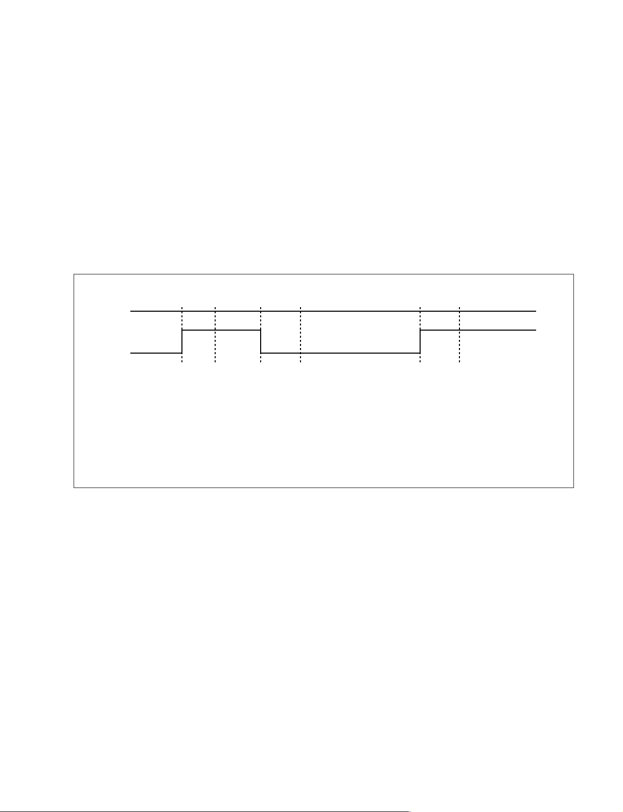
AKB Error (Error 5):
Once every main loop the micro checks the AKB stability by reading the IKR return from the jungle. IKR=1 means that AKB is stable,
IKR=0 means that AKB is unstable. If the AKB status is unstable for 10 seconds, an AKB error is diagnosed. AKB stability is not
checked during the first 20 seconds after AC on.
If this error is diagnosed, the respective NVM register will be updated and the response LED will flash 5 times continually, but the set
will not go into standby. If the AKB status becomes stable, and remains stable for 10 seconds, the LED will stop flashing.
Time/seconds
010
20 30 40 50 60 70 80 90 100
IKR
Return
AB C D E F
A. IKR Return first goes high after 12 seconds
B. Micro begins checking IKR Return status 20 seconds after power on
C. Micro detects IKR return=0
D. Micro detects that IKR has been 0 for 10 seconds; NVM counter is incremented and the LED starts flashing (flashes
5 times, off for 2 seconds, flashes 5 times, etc.)
E. Micro detects that IKR=1; LED continues to flash
F. Micro detects that IKR has been high for 10 seconds; LED stops flashing.
Startup Diagnostic Errors (Errors 6-18, 27, 29-32):
These errors are checked for during the power up sequence before attempting to retrieve data from the NVM.
6 - SCL pin low
7 - SDA pin low
8 - Both the SCL and the SDA pin are low
9 - No acknowledge from the jungle (CXA2076)
10 - No acknowledge from the video switch (CXA2040)
11 - No acknowledge from the tuner
12 - No acknowledge from the MSP
13 - No acknowledge from the NVM
14 - No acknowledge from the CXA2089 video switch (DS10 & DX10)
16 - No acknowledge from the CXA1875 Port Expander (DS10 & DX10)
18 - No acknowledge from the Dynamic Convergence (CXA8070) : Not used for RE-2D
27 - M3L_TXD pin low after Compact Text RAM test
29 - M3L_TXD pin low
30 - M3L_RXD pin low
31 - M3LEN pin low
32 - Compact Text RAM test fail
If any of these errors are detected, the respective NVM register will be incremented. The software will then carry on with the power up
sequence.
– 5 –
KP-51DS1U
KRM-892
General I2C Device Run-time Errors (Errors 19-23):
19 - No acknowledge from Jungle when attempting to initialize
20 - No acknowledge from Jungle when attempting to read registers
21 - AV Switch cannot complete reset during initialization
22 - No acknowledge from AV Switch when attempting to read registers
23 - No acknowledge from NVM when attempting to read or write
If any of these errors are detected, the respective NVM register will be incremented and the software will carry on.
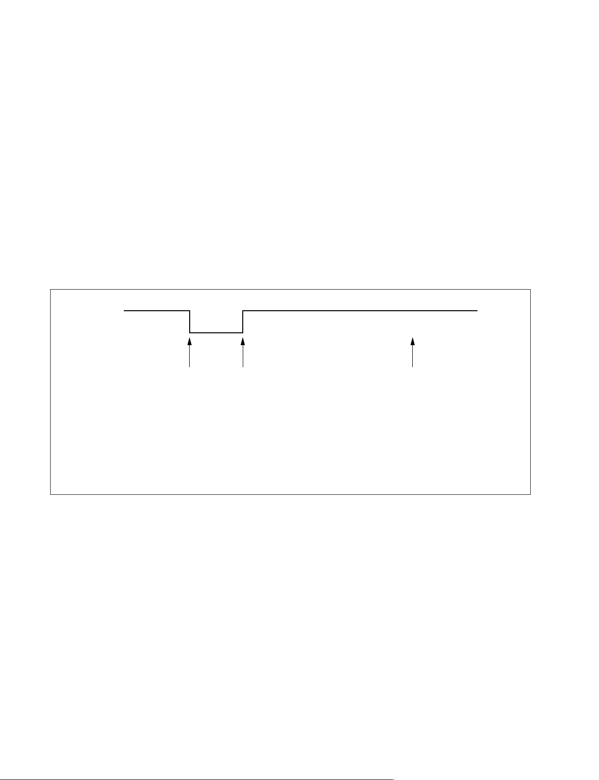
Compact Text Run-time Errors (Errors 26, 28, 33 & 34):
26 - M3L_TXD pin low when checking register 81 (implies that no communication was possible)
28 - M3L_TXD pin low when attempting to initialize (implies that no communication was possible)
33 - Compact Text RAM test fail during initialization of devices
In the case of these errors, the ‘device reset’ pin will be held low for 60ms, causing a hardware reset of Compact Text. Following this
reset, a longer timeout will be allowed for the M3L bus to recover. If the error still exists, the NVM register will be incremented and the
software will carry on.
Device
Rest Pin
AB
A. IKR Return first goes high after 12 seconds
B. Micro begins checking IKR Return status 20 seconds after power on
C. Micro detects IKR return=0
D. Micro detects that IKR has been 0 for 10 seconds; NVM counter is incremented and the LED starts flashing (flashes
5 times, off for 2 seconds, flashes 5 times, etc.)
E. Micro detects that IKR=1; LED continues to flash
F. Micro detects that IKR has been high for 10 seconds; LED stops flashing.
34 - Register 81 check fail, but M3L_TXD pin high (implies that Compact Text has either reset or
become corrupted).
In this case, the ‘device reset’ pin will be held low for 60ms, causing a hardware reset of Compact Text. Compact Text will then be reinitialized and the NVM counter updated. This is the same as for errors 26, 28 and 33 except that the M3L bus timeout is not changed.
Also, during the reset, Compact Text OSD will be disabled (using pin 59 of the micro). Only when the sync registers have been
refreshed twice, will the OSD be enabled.
C
MSP and DSP Run-time Errors (Errors 24 & 25):
Error 24 can be caused by any of the following:
- After MSP initialization, Scart Prescale Register check fail (implies that the MSP has either reset or become corrupted).
- MSP fails to acknowledge reset instruction
- Scart Prescale Register check fail (implies that the MSP has either reset or become corrupted).
Error 25 is caused by:
- DSP test byte corrupted (implies that the DSP has either reset or become corrupted).
For both of these errors, the software will refresh the MSP and DSP registers. If the errors still exist, the NVM counter will be
incremented, and the software will carry on.
– 6 –

KP-51DS1U
KRM-892
Error Display Mode
Error Display Mode is entered by the following sequence of commands:
Standby → Information → Digit 5 → Volume Down → TV
This mode will display a special menu, which will list all possible errors and the number of occurrences of each error (0 – 255, as stored
in the NVM). There will also be a display of the current error (00 if no error). This display mode will appear as follows:
ERROR DISPLAY MODE
Current Error Code = 00
Error Code Occurrences Error Code Occurrences
22 190
3 — 20 0
4 — 21 0
50 220
60 230
70 240
80 254
90 265
10 0 27 89
11 0 28 3
12 0 29 0
13 0 30 0
14 0 31 0
15 3 32 0
16 0 33 3
17 0 34 38
18 6
Whilst in this mode, the number of occurrences of each error can be reset to 0 by TT08.
Only AC off or standby off can exit this mode.
The Current Error Code can also be read by using a TV Error Reader (I2C slave address 42H). This device simply receives 1 data byte,
which is the error number in binary coded decimal form.
– 7 –

KP-51DS1U
KRM-892
TT command table
TT Mode is available by pressing the test key twice. It is exited by pressing 0 twice, or by pressing the Test key, or by pressing the TV
key or by switching the set into standby.
Pressing the Menu key when in TT mode enters in main Test Menu. Pressing the Menu key again enters in the User Menus.
TT Modes 40-49 require TV to be in program 59 before the command is accepted. Some Test models are dependant upon the model.
TT command Meaning
<Menu> Enter into service menu
00 Exit from TT mode
01 Set picture level to maximum
02 Set picture level to minimum
03 Set volume to 35%
04 Set volume to 50%
05 Set volume to 65%
06 Set volume to 80%
07 Ageing mode enable / disable
08 Shipping condition
09 Reset language select menu on power up
11 Sub Picture adjustment (use red / yellow)
12 Sub Colour adjustment (use red / yellow)
13 Sub Brightness adjustment (use red / yellow)
14 Text H-Position
16 Picture level 50 %
21 Destination A/D (East Menu / West Text)
22 Destination L (West Menu / West Text)
23 Destination E ( West Menu / West Text)
24 Destination U (West Menu / West Text)
25 Destination D (East Menu / Greek Text)
26 Destination B (East Menu / West Text)
27 Destination K (East Menu / East Text)
28 Destination R (Russian Menu / Russian Text)
32 Digital Status on/off
41 Re-initialize NVM
42 Re-initialize Geometry settings
43 Default programme info in NVM with Pencoed factory channel setup
44 Default favourite pages to 100, 101, 102, 103
45 Switch off all Channel Locks
46 Dealer commander mode (pending)
47 Default MSP Settings
48 Restore NVM test byte Undo TT49
49 Delete NVM test byte Sets virgin NVM
52 Noise on Left Speaker
53 Noise on Right Speaker Only
– 8 –

KP-51DS1U
KRM-892
54 Noise on Centre Speaker Only
55 Noise on Surround Speaker Only
56 Set Colour to minimum and Picture to maximum
57 Set Colour & Picture to minimum and adjust sub-brightness
68 Pre-Set AV Labels
69 Picture Blanking Pulse Enable/ Disable
72 Balance Left/ Right (Press RED Key for balance left, YELLOW for balance right, and GREEN for centre balance
73 Dual sound Headphones (GREEN key for A, BLUE key for B)
74 Dual sound Speakers (GREEN key for A, BLUE key for B)
77 Setup Trap Switch
78 Set Screen Size
79 Wide Setup
81 Velocity Modulation ON
82 Velocity Modulation OFF
83 Special Picture Mode - Personal mode, reset & brightness =0
84 Text Interlace Odd (Non Interlace mode = 3)
85 Text Interlace Even (Non interlace mode = 2)
86 Auto Cut Off ENABLE
87 Auto Cut Off DISABLE
88 Diagnostics OFF
89 Diagnostics ON
91 Clear & Disable OSD
92 Enable OSD
93 D / K Nicam Enable
94 D / K Nicam Disable
95 Reset language select menu on power up
96 Set all programme labels to default
97 MHEG mode on/off
– 9 –
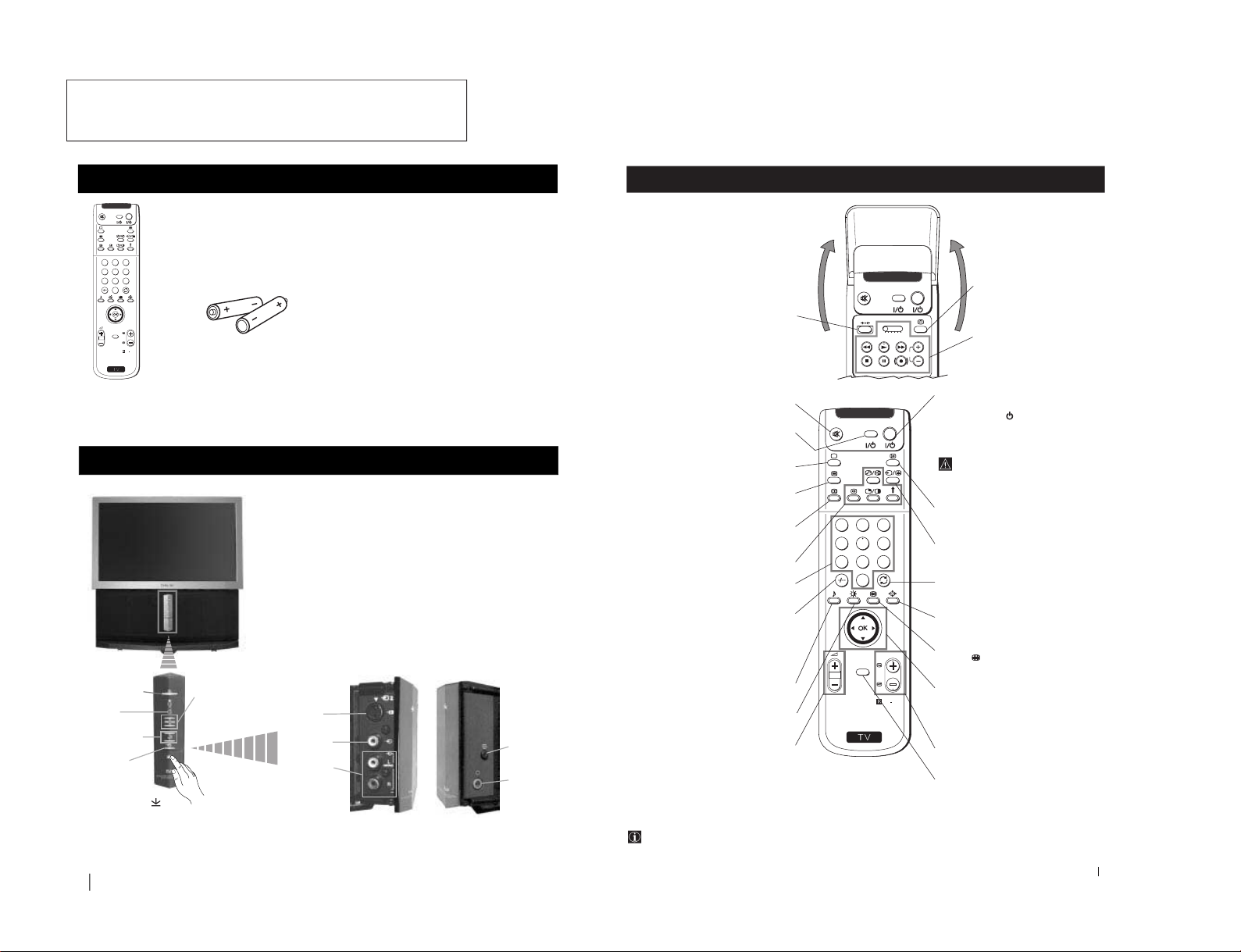
4
One Remote Control
(RM-892)
Overview of Projection TV Buttons
(conectores lado izquierdo) (conectores lado derecho)
Checking the Accessories Supplied
Overview
S
RM
892
PROGR
MENU
1
4
7
2
5
8
0
3
6
9
VIDEO TV
Two batteries (R6 type)
On/Off Switch
Standby
indicator
Volume control
buttons
Selecting
input source
S Video
Input jack
Video Input
jack
Audio Input
jacks
Auto
Convergence
button
Headphone
jack
(left side connectors)
(right side connectors)
Press on the mark , on
the front of the projection
TV to reveal the front
connectors.
Programme up
or down buttons
(selects TV channels)
Overview
s
The operating instructions mentioned here are partial abstracts
5
S
RM
892
PROGR
MENU
1
4
7
2
5
8
0
3
6
9
K
VIDEO TV
VIDEO TV
VTR 1 2 3 4 DVD
CH
Getting Started - Overview
Getting Started - Overview
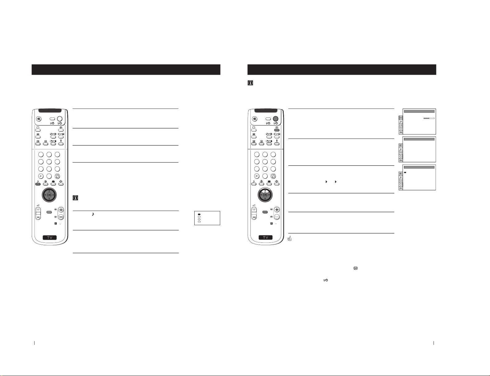
Overview of Remote Control Buttons
To Temporarily Switch Off projection
TV
Press to temporarily switch off TV (the
standby indicator
on projection TV lights
up). Press again to switch on TV from
standby mode.
To save energy we recommend switching off
completely when TV is not in use.
After 15-30 minutes without a
signal and without any button being
pressed, the projection TV switches
automatically into standby mode.
Displaying On Screen Information
Press to display all on-screen indications.
Press again to cancel.
Selecting Input source
Press repeatedly until the desired input
symbol of the source appears on the screen.
Back to the channel last watched
Press to watch the last channel selected
(watched for at least 5 seconds).
Selecting Screen format
Press repeteadly to change the format of the
screen.
This button only works in Teletext mode.
Function
associated to this button does not
work with this set.
Joystick for menu selection
4 Scroll Up
$ Scroll Down
Z Previous menu or selection
z Next menu or selection
OK Confirms your selection
Selecting channels
Press to select the next or previous channel.
Displaying the menu system
Press to display the menu on the screen.
Press again to remove the menu display
from the screen.
Muting the Sound
Press to mute TV sound.
Press again to restore the sound.
VCR on/off
Press to switch your VCR on or off.
Selecting TV mode
Press to switch off Teletext or video input.
Selecting Teletext
Press to switch on Teletext.
Displaying EPG
Press to display the Electronic Programme
Guide (EPG). Press again to switch off EPG.
These buttons do not work on this set.
Selecting channels
Press to select channels.
For double-digit programme numbers, e.g. 23,
press -/-- first, then the buttons 2 and 3.
If you enter an incorrect first digit, this should
be corrected by entering another digit (0-9)
and then selecting -/-- button again to enter
the programme number of your choice.
+++++++++++++++...
Selecting Sound mode
Press repeatedly to change the sound mode.
+++++++++++++++++...
Selecting Picture mode
Press repeatedly to change the picture mode.
+++++++++++++++++...
Adjusting TV Volume
Press to adjust the volume of the TV.
Besides TV functions, all coloured buttons as well as green
symbols are also used for Teletext operation. For more details,
please refer to the "Teletext" section of this instruction manual.
This button does not work on this set.
Displaying the time
Press to switch the time on or off
(available only when teletext is
broadcast).
VCR operation
For more details, please refer to
the section "Remote Control of
other Sony Equipment"
from the Operating Instruction Manual. The page numbers of
the Operating Instruction Manual remein as in the manual.
SECTION 2
GENERAL
– 10 –
6
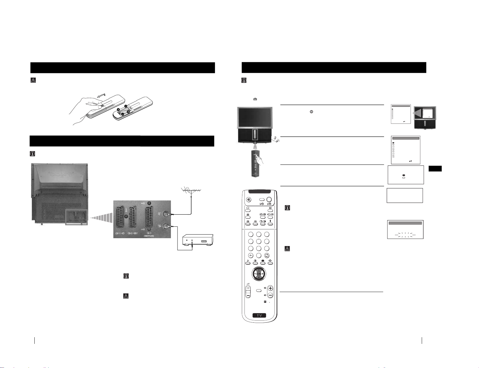
Installation
Make sure you insert the batteries using the correct polarities.
Always remember to dispose of used batteries in an environmental friendly way.
Inserting Batteries into the Remote Control
Connecting cables are not supplied.
Connecting the Aerial and VCR
OUT
IN
VCR
The Scart lead is optional.
If you use this optional connection
it can improve picture and sound quality
when using a VCR.
If you do not use a SCART lead, after
automatically tuning the projection TV
refer to the "Manually Tuning the TV"
section of this instruction manual, to tune
in the projection TV to the output of your
VCR. Also refer to your VCR instruction
manual to find out how to find the output
channel of your VCR.
Installation
7
GB
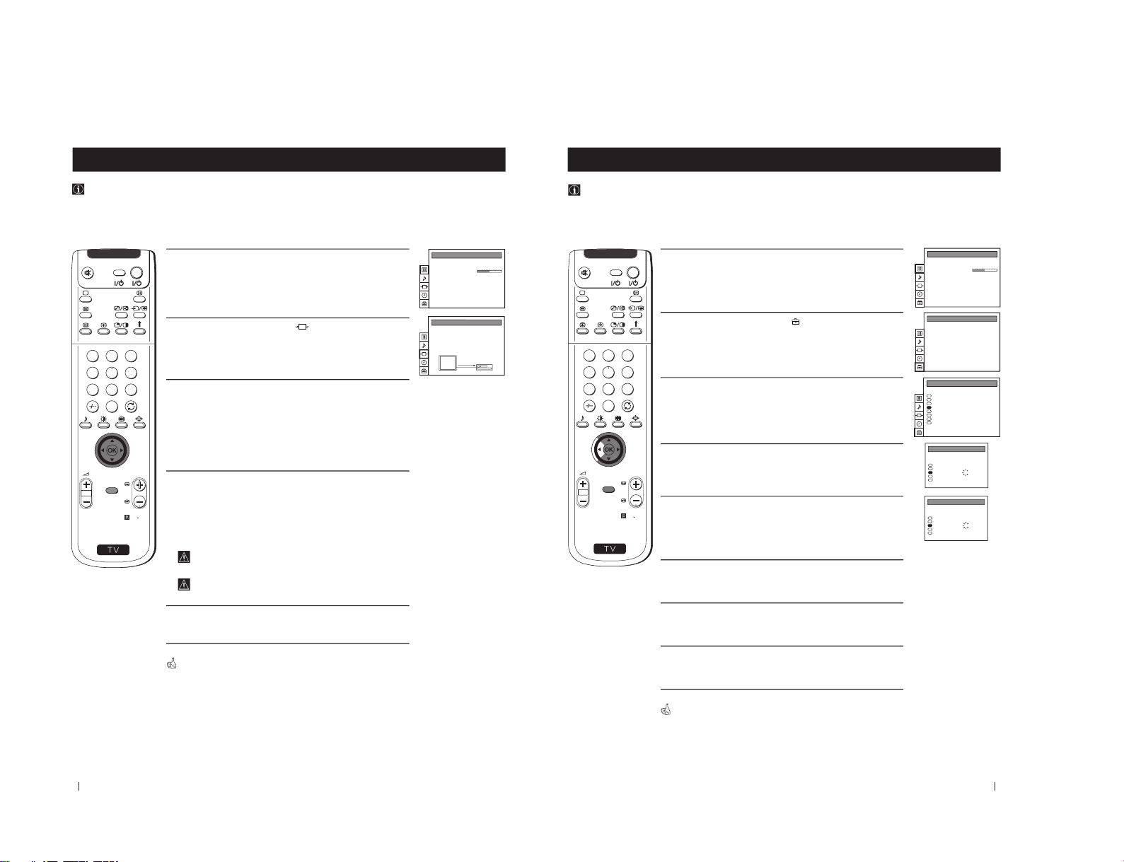
First Time Operation
The first time you switch on your TV, a sequence of menu screen appear on the TV enabling you to 1) choose the language
of the menu screen, 2) search and stores all available channels (TV Broadcast) and 3) change the order in which the channels
(TV Broadcast) appear on the screen.
However, if you need to change the language menu, change the country, change or repeat the tuning (e.g. when you move
house) or rearrange again the order of the channels afterwards, you can do that by selecting the appropriate menu in
the (PRESET)
.
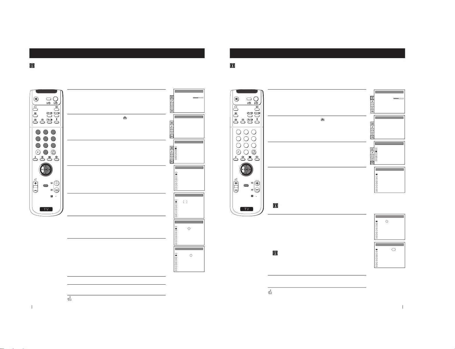
Switching on the Projection TV and Automatically Tuning
1
Connect the Projection TV plug to the mains socket (220-240V AC,
50 Hz). Press the on/off button on your projection TV set to
switch on. The first time you press this button the Language menu
displays automatically on the screen.
2
Push the joystick on the remote control to $ or 4 to select the
language, then press OK to confirm your selection. From now on all
the menus will appear in the selected language.
3
The Auto Tuning menu appears on the screen in the selected
language, then press the OK button on the remote control to select
YES.
4
A new menu appears automatically on the screen asking you to
check that the aerial is connected. Confirm that the aerial is connected
and then press the OK button to start the automatic tuning.
The TV starts to automatically search and store all available
channels (TV Broadcast) for you and the message “Searching”
flashes on the screen until all available channels will be stored.
If any analogue channel is tuned, it will be stored in
programme numbers 91 to 99 but only in the case that these
positions are free. However, if you wish to tune in any
analogue channel and store it in the programme number of
your choice, please refer to the section "Manually Tuning the
TV" of this instruction manual.
This procedure could take some minutes. Please, be patient and
do not press any button. Otherwise the automatic tuning will
not be completed.
continued...
First Time Operation
LANGUAGE
English
Deutsch
Français
Italiano
Nederlands
Polski
Česki
Magyar
Eλλnvιkά
Select Language:
Confirm: OK
LANGUAGE
English
Deutsch
Français
Italiano
Nederlands
Polski
Česki
Magyar
Eλλnvιkά
Select Language:
Confirm: OK
LANGUAGE
English
Deutsch
Français
Italiano
Nederlands
Polski
Česki
Magyar
Eλλnvιkά
Select Language:
Confirm: OK
Do you want to start
automatic tuning?
Yes
No
Confirm: OK
Please confirm that
antenna is connected
Confirm: OK
PROG
- -
Searching
AUTO PROGRAMME
SYS
DIG
CHAN
C 26
SERV
- -
LABEL
- - - - -
S
RM
892
PROGR
MENU
1
4
7
2
5
8
0
3
6
9
VIDEO TV
– 11 –
8
First Time Operation
S
RM
892
PROGR
MENU
1
4
7
2
5
8
0
3
6
9
VIDEOTV
PROG SYS CHAN LABEL
PROGRAMME SORTING
DIG
DIG
DIG
DIG
DIG
DIG
DIG
DIG
DIG
DIG
0
1
2
3
4
5
6
7
8
9
BBC-W
MV-CH
TVE-1
TVE-2
ANT-3
TELE 5
C PLUS
- - - - -
- - - - CNN -
C 28
C 40
C 41
C 31
C 34
C 27
C 47
C 44
C 23
C 35
Select PROG: + OK
Exit: MENU
DIG
DIG
DIG
DIG
DIG
DIG
DIG
DIG
DIG
DIG
0
1
2
3
4
5
6
7
8
9
MV-CH
TVE-1
TVE-2
ANT-3
TELE 5
C PLUS
- - - - -
- - - - CNN BBC-W
C 40
C 41
C 31
C 34
C 27
C 47
C 44
C 23
C 35
C 28
PROGRAMME SORTING
Select Position:
Confirm: OK
SYS CHAN LABELPROG
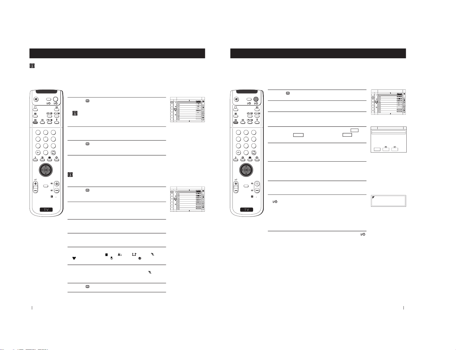
5
After all available channels are captured and stored, the
Programme Sorting menu appears automatically on the screen
enabling you to change the order in which the channels appear
on the screen.
a)
If you do not wish to change the channel order, go to step 6.
b)
If you wish to change the channel order:
1
Push the joystick on the remote control to
$
or
4
to select the
programme number with the channel (TV Broadcast) you wish to
rearrange, then push to
z
.
2
Push the joystick to
$
or
4
to select the new programme number
position for your selected channel (TV Broadcast), then press
OK
.
The selected channel now moves to its new programme
position and the other channels move accordingly.
3
Repeat steps b1) and b2) if you wish to change the order of the
other channels.
6
Press the
MENU
button to exit and return to the normal TV screen.
Your projection TV is now ready for use.
First Time Operation
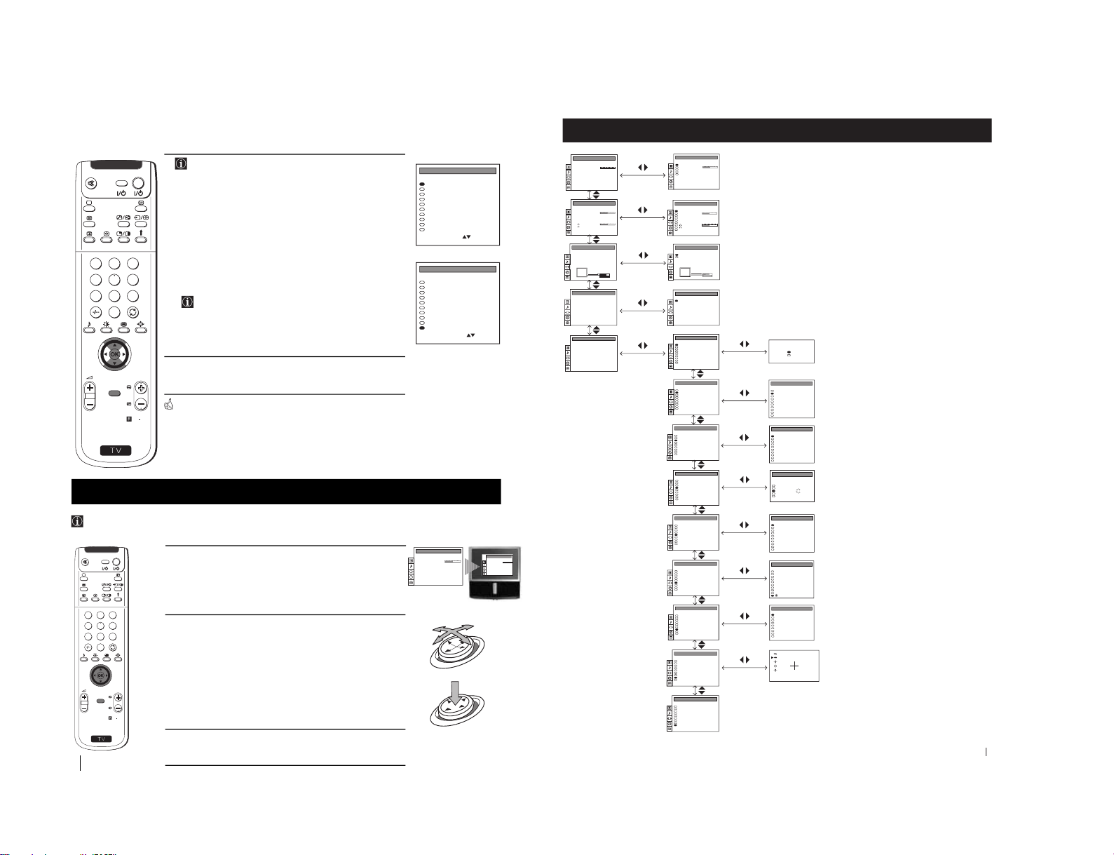
1
Press the
MENU
button to switch the first level menu on.
2
•To higlight the desired menu or option, push the joystick to
4
or
$
.
•To enter to the selected menu or option, push to
z
•To return to the last menu or option, push to
Z
.
•To alter settings of your selected option, push to
$
/
4
/
Z
or
z
.
•To confirm and store your selection, press
OK
.
3
Press the
MENU
button to remove the menu from the screen.
Your projection TV uses an on-screen menu system to guide you through the operations. Use the following buttons on the Remote
Control to operate the menu system:
Introducing the Menu system
S
RM
892
PROGR
MENU
1
4
7
2
5
8
0
3
6
9
VIDEO TV
OK
push to
$/4/Z or z
press OK
PICTURE CONTROL
Personal
Wide
Composite
Picture Mode
Contrast
Reset
Format
Digital Signal
PICTURE CONTROL
Personal
Wide
Composite
Picture Mode
Contrast
Reset
Format
Digital Signal
9
PICTURE CONTROL
Personal
Wide
Composite
Picture Mode
Contrast
Reset
Format
Digital Signal
Auto Programme
Manual Programme Preset
Further Programme Preset
AV Label Preset
Programme Sorting
Parental Lock
Language
Convergence
Digital Subtitles Off
PRESET
Menu System
Menu System
On Screen display Menus Guide
(For different adjustments, please refer to
the section "Adjusting the Picture")
(For different adjustments, please refer to
the section "Adjusting the Sound" )
(For more details, please refer to the
section "Selecting the output source for the
Euro AV connectors")
(For more details, please refer to the
section "Using the Sleep Timer")
(For more details, please refer to the
section "Switching on the projection TV
and automatically tuning")
(For more details, please refer to the
section "Manually Tuning the TV")
(For more details, please refer to the
section "Using the Further Programme
Preset function"
(For more details, please refer to the
section "Labelling the Input Sources")
(For more details, please refer to the
section "Switching on the projection TV
and automatically tuning")
(For more details, please refer to the
section "Locking Programmes").
(For more details, please refer to the
section "Switching on the projection TV
and automatically tuning")
(For more details, please refer to the
section "Adjusting Colour Registration
(Convergence)".
(For more details, please refer to the
section "Displaying subtitles for digital
channels".
PICTURE CONTROL
Personal
Wide
Composite
Picture Mode
Contrast
Reset
Format
Digital Signal
SOUND CONTROL
Personal
Off
Mono
0
Mono
Main
Sound Mode
Balance
Reset
Spatial
Dual Sound
Volume Offset
Volume
Dual Sound
Speaker
SOUND CONTROL
Personal
Off
Mono
0
Mono
Main
Sound Mode
Balance
Reset
Spatial
Dual Sound
Volume Offset
Volume
Dual Sound
Speaker
TIMER
1:00Sleep Timer
TIMER
OffSleep Timer
Do you want to start
automatic tuning?
Yes
No
Confirm: OK
Auto Programme
Manual Programme Preset
Further Programme Preset
AV Label Preset
Programme Sorting
Parental Lock
Language
Convergence
Digital Subtitles Off
PRESET
PROG SYS CHAN LABEL
PROGRAMME SORTING
I
DIG
I
DIG
I
I
DIG
DIG
DIG
DIG
0
1
2
3
4
5
6
7
8
9
BBC-W
MV-CH
TVE-1
TVE-2
ANT-3
TELE 5
C PLUS
- - - - -
- - - - CNN -
C 28
C 40
C 41
C 31
C 34
C 27
C 47
C 44
C 23
C 35
Auto Programme
Manual Programme Preset
Further Programme Preset
AV Label Preset
Programme Sorting
Parental Lock
Language
Convergence
Digital Subtitles Off
PRESET
0
1
2
3
4
5
6
7
8
9
PROG CHAN
MV-CH
TVE-1
TVE-2
ANT-3
TELE 5
C PLUS
- - - - -
- - - - CNN TWO
LABEL
C 40
C 41
C 31
C 34
C 27
C 47
C 44
C 23
C 23
C 23
MANUAL PROGRAMME PRESET
I
DIG
I
DIG
I
I
DIG
DIG
DIG
DIG
SYS
06
02
03
04
05
01
SERV
Auto Programme
Manual Programme Preset
Further Programme Preset
AV Label Preset
Programme Sorting
Parental Lock
Language
Convergence
Digital Subtitles Off
PRESET
VIDEO CONNECTION
[TV - - - - - - -]
[AV1 - - - - - - -]
TV Screen
Output
TV
AV1
VIDEO CONNECTION
[TV - - - - - - -]
[AV1 - - - - - - -]
TV Screen
Output
TV
AV1
Auto Programme
Manual Programme Preset
Further Programme Preset
AV Label Preset
Programme Sorting
Parental Lock
Language
Convergence
Digital Subtitles Off
PRESET
Off
Off
AV1
Off
AV2
Off
Off
Off
Off
Off
On
On
On
On
On
On
On
0
1
2
3
4
5
6
7
8
9
PROG AFT DECODER
FURTHER PROGRAMME PRESET
Auto Programme
Manual Programme Preset
Further Programme Preset
AV Label Preset
Programme Sorting
Parental Lock
Language
Convergence
Digital Subtitles Off
PRESET
Auto Programme
Manual Programme Preset
Further Programme Preset
AV Label Preset
Programme Sorting
Parental Lock
Language
Convergence
Digital Subtitles Off
PRESET
I
DIG
I
DIG
I
I
DIG
DIG
DIG
DIG
0
1
2
3
4
5
6
7
8
9
PROG
MV-CH
TVE-1
TVE-2
ANT-3
TELE 5
C PLUS
- - - - -
- - - - CNN -
- - - - -
C 40
C 41
C 31
C 34
C 27
C 47
C 44
C 23
C 35
C 28
SYS CHAN LABEL
PARENTAL LOCK
Auto Programme
Manual Programme Preset
Further Programme Preset
AV Label Preset
Programme Sorting
Parental Lock
Language
Convergence
Digital Subtitles Off
PRESET
AV LABEL PRESET
AV1
RGB
AV2
YC2
AV3
INPUT LABEL
- - - - -
- - - - -
- - - - -
- - - - -
- - - - -
Auto Programme
Manual Programme Preset
Further Programme Preset
AV Label Preset
Programme Sorting
Parental Lock
Language
Convergence
Digital Subtitles Off
PRESET
LANGUAGE
English
Deutsch
Français
Italiano
Nederlands
Polski
Česki
Magyar
Eλλnvιkά
Auto Programme
Manual Programme Preset
Further Programme Preset
AV Label Preset
Programme Sorting
Parental Lock
Language
Convergence
Digital Subtitles Off
PRESET
– 12 –
10
Menu System
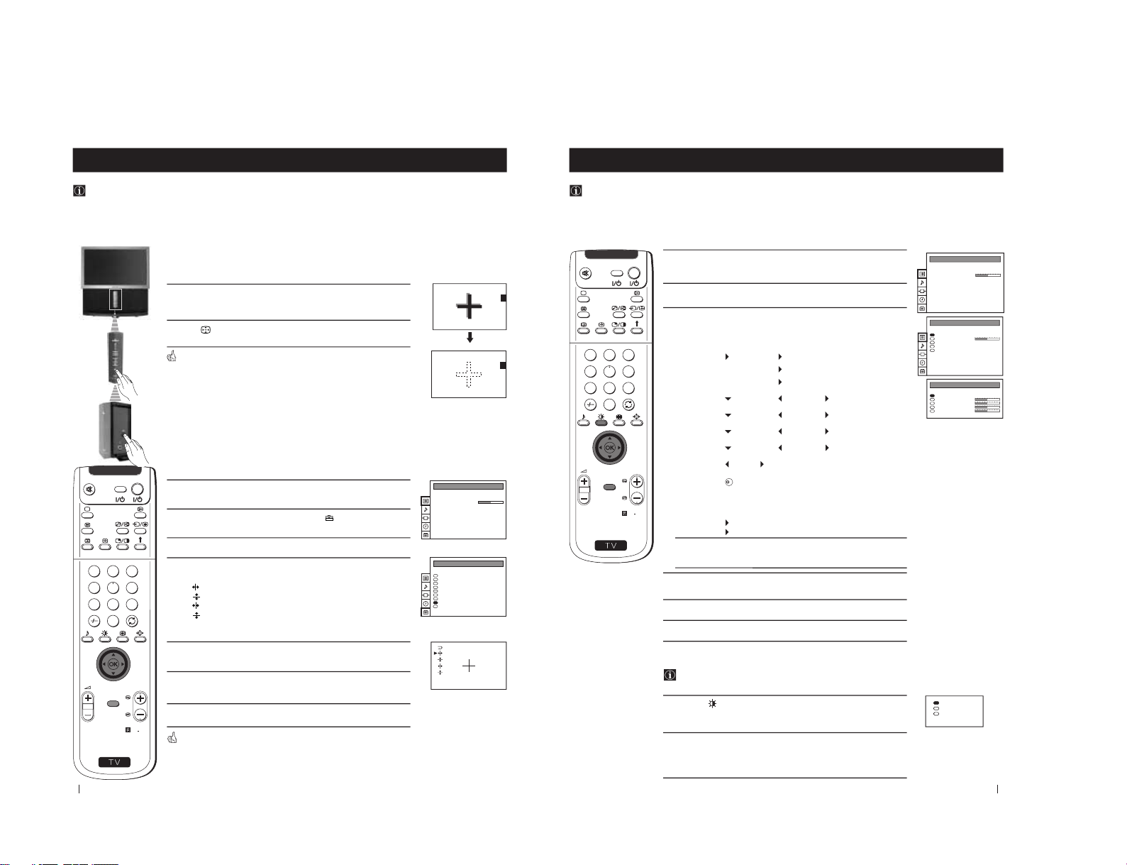
Adjusting Colour Registration (Convergence)
Due to the earth’s magnetism, the picture might become undefined and you could see different colours on the outlines of
the images. In that case, proceed as follows:
Auto converge the Red, Green, and Blue
Lines
1
Press on the mark , on the front of the projection TV to reveal the
front connectors.
2
Press
button on the projection TV.
The Auto Convergence function works for about 30 seconds. When the
white cross disappears from the screen, your projection TV is ready for use.
Notes:
The Auto Convergence function does not work:
• when no signal is input.
• when the input signal is weak.
• when the screen is exposed to spotlights or direct sunlight.
• when you watch the teletext broadcast.
If you wish a more accurate convergence
adjustment
1
Press the MENU button on the remote control to display the menu
on the screen.
2
Push the joystick to $ to select the symbol
, then push to z to
enter to the PRESET menu.
3
Push the joystick to $ or 4 to select Convergence, then push to z.
4
Push the joystick to $ or 4 to select “the line” (vertical and
horizontal lines in red and blue) you want to adjust.
: red vertical line (left/right adjustment)
: red horizonta line (up/down adjustment)
: blue vertical line (left/right adjustment)
: blue horizontal line (up/down adjustment)
Then press the OK button.
5
Push the joystick repeatedly to $, 4, Z or z to converge the selected
line with the green line in the centre, then press OK to confirm.
6
Repeat steps 4 and 5 to adjust the other lines, until all the lines have
overlapped to form a white cross.
7
Press the MENU button to exit and return to the normal TV screen.
Your projection TV is ready for use.
Menu System
PICTURE CONTROL
Personal
Wide
Composite
Picture Mode
Contrast
Reset
Format
Digital Signal
Auto Programme
Manual Programme Preset
Further Programme Preset
AV Label Preset
Programme Sorting
Parental Lock
Language
Convergence
Digital Subtitles Off
PRESET
S
RM
892
PROGR
MENU
1
4
7
2
5
8
0
3
6
9
VIDEO TV
11
S
RM
892
PROGR
MENU
1
4
7
2
5
8
0
3
6
9
VIDEO TV
1
Press the MENU button on the remote control to display the menu
on the screen.
2
Push the joystick to z to enter the PICTURE CONTROL menu.
3
Push the joystick to $ or 4 to select the item you wish to change,
then push to z.
Refer to the table below to chose the item and for the effect of each
control:
4
Push the joystick to Z or z to alter the selected item, then press the
OK button to store the new adjustment.
5
Repeat steps 3 and 4 to alter the other items.
6
Press the MENU button to exit and return to the normal TV screen.
Picture Mode
Picture Mode
Personal (for individual settings)
Movie (for films)
Live (for live broadcast programmes)
Brightness
*
Darker
Brighter
Colour
*
Less
More
Sharpness
*
Softer
Sharper
Hue
**
Greenish
Reddish
Contrast
Less
More
Reset Resets picture to the factory preset levels.
Format (for detalis refer to the section "Changing the
Screen Mode")
Digital Signal
Composite (standard picture quality)
RGB
***
(improves the picture quality)
*
Can only be altered if Personal Mode is selected.
**
Only avalaible for NTSC colour signal (e.g: USA video tapes).
***
Not available in 4:3 format screen mode.
Adjusting the Picture
Although the picture is adjusted at the factory, you can modify it to suit your own taste.
Menu System
Changing the Picture Mode Quickly
You can quickly change the Picture Mode without entering the
Picture Control menu screen.
1
Press the
button on the remote control to directly access the
Picture Mode.
2
Push the joystick to $ or 4 to select your desired picture mode
(Personal, Movie or Live), then press the OK button to remove the
display from the screen.
PICTURE CONTROL
Personal
Wide
Composite
Picture Mode
Contrast
Reset
Format
Digital Signal
PICTURE CONTROL
Personal
Wide
Composite
Picture Mode
Contrast
Reset
Format
Digital Signal
PICTURE MODE
Personal
Picture Mode
Brightness
Colour
Sharpness
Hue
K
Personal
Movie
Live
Menu System
– 13 –
12
S
RM
892
PROGR
MENU
1
4
7
2
5
8
0
3
6
9
VIDEO TV
1
Press the MENU button on the remote control to display the menu
on the screen.
2
Push the joystick to z button to enter the PICTURE CONTROL
menu.
3
Push the joystick to $ to select Format, then push to z.
4
Push the joystick to $ or 4 to select Format, Scroll or Auto 16:9.
5
Format
Push the joystick to z to enter to the menu, then push to Z or z
repeatedly to select one of the following modes:
• Smart: imitation of wide screen effect (16:9) for 4:3 broadcasts.
• 4:3: conventional 4:3 picture.
• Zoom: imitation of wide screen effect (16:9) for movies broadcast
in cinemascopic format.
• Wide: for 16:9 broadcasts.
Press the OK button.
6
Scroll
You can use Scroll to move the screen up- or downwards in
order to see the cut-off parts. This function only works if you
selected Zoom mode or Smart mode in step 5.
Push the joystick to z to enter to the menu, then push to Z or z to
adjust the screen position over a range of -5 to +5. Press the OK
button.
7
Auto 16:9
Push the joystick to z to enter to the menu, then push to Z or z to
select:
On: if you wish the TV set to switch automatically to wide format if
a 16:9 broadcast is detected or
Off: for normal mode.
Press the OK button.
8
Press the MENU button to exit and return to the normal TV screen.
Changing the screen mode
Using this Screen Mode feature you can change the aspect ratio of the screen.
Menu System
Changing the Format Screen Quickly
You can quickly change the format screen without entering the
Picture Control menu screen.
1
Press the button on the remote control repeatedly to select your
desired format screen mode (Smart, 4:3, Zoom or Wide).
PICTURE CONTROL
Personal
Wide
Composite
Picture Mode
Contrast
Reset
Format
Digital Signal
PICTURE CONTROL
Personal
Wide
Composite
Picture Mode
Contrast
Reset
Format
Digital Signal
FORMAT
Wide
0
On
Format
Scroll
Auto 16:9
Smart
4:3
Zoom
Wide
Menu System
13
1
Press the MENU button on the remote control to display the menu
on the screen.
2
Push the joystick to $ to select the
symbol, then push to z to enter
to the SOUND CONTROL menu.
3
Push the joystick to $ or 4 to select the item you wish to change,
then push to z.
Refer to the table below to chose the item and for the effect of each
control.
Sound Mode
Mode
Personal (for individual settings)
Rock
Jazz
Pop
Treble
*
Less
More
Bass
*
Less
More
Balance
Left
Right
Reset Resets picture to the factory preset levels.
Spatial
On: acoustic sound effect
Off: normal
Dual Sound • For a stereo broadcast:
Mono
Stereo
• For a bilingual broadcast:
Mono (for mono channel if available)
A (for channel 1)
B (for channel 2)
Volume Offset
-12 ..........
+12
The channel volume level can be adjusted over a
range of -12 to +12.
Headphones:
ll
ll
l Volu me
Less
More
ll
ll
l Dual Sound • For a stereo broadcast:
Mono
Stereo
• For a bilingual broadcast:
Mono (for mono channel if available)
A (for channel 1)
B (for channel 2)
Speaker
Main: sound from projection TV set
Centre in: sound from external amplifier
*
Can be only altered if "Personal" mode is selected.
Adjusting the Sound
Although the sound is adjusted at the factory, you can modify it to suit your own taste.
Menu System
S
RM
892
PROGR
MENU
1
4
7
2
5
8
0
3
6
9
VIDEO TV
PICTURE CONTROL
Personal
Wide
Composite
Picture Mode
Contrast
Reset
Format
Digital Signal
SOUND CONTROL
Personal
Off
Mono
0
Mono
Main
Sound Mode
Balance
Reset
Spatial
Dual Sound
Volume Offset
Volume
Dual Sound
Speaker
SOUND MODE
Personal
Mode
Treble
Bass
K
Continued...
Menu System
– 14 –
14
S
RM
892
PROGR
MENU
1
4
7
2
5
8
0
3
6
9
VIDEO TV
4
Push the joystick to Z or z to alter the selected item, then press the
OK button to store the new adjustment.
5
Repeat steps 3 and 4 to alter the other items.
6
Press the MENU button to exit and return to the normal TV screen.
Changing Sound Mode Quickly
You can quickly change Sound mode without entering the Sound
Control menu screen.
1
Press the
button on the remote control to directly access to the
Sound Mode.
2
Push the joystick to $ or 4 to select your desired sound mode
(Personal, Rock, Jazz or Pop), then press the OK button to remove
the display from the screen.
Menu System
Personal
Rock
Jazz
Pop
Menu System
15
S
RM
892
PROGR
MENU
1
4
7
2
5
8
0
3
6
9
VIDEO TV
Using the Sleep Timer
You can select a time period for the TV to switch itself automatically into the standby mode.
1
Press the MENU button on the remote control to display the menu
on the screen.
2
Push the joystick to $ button to select the t symbol, then push to z
to enter to the TIMER menu.
3
Push the joystick to z, then push to Z or z repeatedly to set the
time period delay
Off
0:30
1:00..... 4:00 hours
4
Press the OK button.
5
Press the MENU button to exit and return to the normal TV screen.
One minute before the projection TV switches into standby mode, the
indication 0:01 is displayed on the screen automatically.
Notes: • When watching the TV, press the
button on the remote
control to display the time remaining.
• To return to normal operation from standby mode,
press the TV
button on the remote control.
Menu System
PICTURE CONTROL
Personal
Wide
Composite
Picture Mode
Contrast
Reset
Format
Digital Signal
TIMER
OffSleep Timer
TIMER
1:00Sleep Timer
Menu System
– 15 –
16
S
RM
892
PROGR
MENU
1
4
7
2
5
8
0
3
6
9
VIDEO TV
Menu System
Menu System
Manually Tuning the TV
Use this function to preset channels or a video input source one by one to the programme order of your choice.
1
Press the MENU button on the remote control to display the
menu on the screen.
2
Push the joystick to $ to select the
symbol, then push to z to
enter to the PRESET menu.
3
Push the joystick to $ or 4 to select Manual Programme Preset,
then push to z.
4
Push the joystick to $ or 4 to select on which programme number
you want to preset a channel, then push to z.
5
Push the joystick to $ or 4 to select the TV Broadcast system (I for
analogue channels or DIG for digital channels) or a video input
source (AV1, AV2...), then push to z to highlight the number digit
of CHAN column.
6
Press the number buttons to enter the channel number of the TV
Broadcast or push the joystick to 4 or $ to search for the next
available channel.
If you do not wish to store this channel, push the joystick to 4 or
$ to continue searching for the desired channel.
7
a) For analogue channels or video input source:
If this is the desired channel you wish to store, press the OK
button.
b) For digital channels:
Push the joystick to z to enter to the SERV column, then press
the number buttons or push to 4 or $ to select the service
number of your selected channel.
Press the OK button to store.
8
Repeat steps 4 to 7 if you wish to store more channels.
9
Press the MENU button to exit and return to the normal TV
screen.
Your projection TV is now ready for use.
PICTURE CONTROL
Personal
Wide
Composite
Picture Mode
Contrast
Reset
Format
Digital Signal
Auto Programme
Manual Programme Preset
Further Programme Preset
AV Label Preset
Programme Sorting
Parental Lock
Language
Convergence
Digital Subtitles Off
PRESET
Auto Programme
Manual Programme Preset
Further Programme Preset
AV Label Preset
Programme Sorting
Parental Lock
Language
Convergence
Digital Subtitles Off
PRESET
0
1
2
3
4
5
6
7
8
9
PROG CHAN
MV-CH
TVE-1
TVE-2
ANT-3
TELE 5
C PLUS
- - - - -
- - - - CNN BBC-TWO
LABEL
C 40
C 41
C 31
C 34
C 27
C 47
C 44
C 23
C 23
C 23
MANUAL PROGRAMME PRESET
I
DIG
I
DIG
I
I
DIG
DIG
DIG
DIG
SYS
06
02
03
04
05
01
SERV
0
1
2
3
4
5
6
7
8
9
PROG CHAN
MV-CH
TVE-1
TVE-2
ANT-3
TELE 5
C PLUS
- - - - -
- - - - CNN BBC-TWO
LABEL
C 40
C 41
C 31
C 34
C 27
C 47
C 44
C 23
C 23
C 23
MANUAL PROGRAMME PRESET
I
DIG
I
DIG
I
I
DIG
DIG
DIG
DIG
SYS
06
02
03
04
05
01
SERV
0
1
2
3
4
5
6
7
8
9
PROG CHAN
MV-CH
TVE-1
TVE-2
ANT-3
TELE 5
C PLUS
- - - - -
- - - - CNN BBC-TWO
LABEL
C 40
C 41
C 31
C 34
C 27
C 47
C 44
C 23
C 23
C 23
MANUAL PROGRAMME PRESET
I
DIG
I
DIG
I
I
DIG
DIG
DIG
DIG
SYS
06
02
03
04
05
01
SERV
0
1
2
3
4
5
6
7
8
9
PROG CHAN
MV-CH
TVE-1
TVE-2
ANT-3
TELE 5
C PLUS
- - - - -
- - - - CNN TWO
LABEL
C 40
C 41
C 31
C 34
C 27
C 47
C 44
C 23
C 23
C 23
MANUAL PROGRAMME PRESET
I
DIG
I
DIG
I
I
DIG
DIG
DIG
DIG
SYS
06
02
03
04
05
01
SERV
17
PICTURE CONTROL
Personal
Wide
Composite
Picture Mode
Contrast
Reset
Format
Digital Signal
Menu System
Menu System
Using the "Further Programme Preset" function
With this feature you can:
a) Even normally the automatic fine tuning (AFT) is operating, however you can manually fine-tune the TV (only available
on analogue channels) to obtain a better picture reception if the picture is distorted or
b) preset the AV3 output for the programme positions of channels with scrambled signals (eg from a pay TV decoder). In
this way a connected VCR records the unscrambled signal.
1
Press the MENU button on the remote control to display the menu
on the screen.
2
Push the joystick to $ to select the
symbol, then push to z to
enter to the PRESET menu.
3
Push the joystick to $ or 4 to select Further Programme Preset,
then push to z.
4
Push the joystick to $ or 4 to select the relevant programme
number, then push to z repeatedly to select:
a) AFT or
b) DECODER.
The selected item changes colour.
AFT will only be available on analogue channels.
5
a) AFT
Push the joystick to $ or 4 to fine tune the channel frequency over a
range of -15 to +15, then press the OK button.
Repeat steps 4 and 5a) if you wish to fine tune other channels.
b) DECODER
Push the joystick to $ or 4 to select AV
3
, then press the OK button.
The picture from the decoder connected to the Euro AV :3 on
the back of the projection TV will appear on this programme
number.
Repeat steps 4 and 5b) to preset the AV3 output for other
programme positions.
6
Press the MENU button to exit and return to the normal TV screen.
Your projection TV is now ready for use.
S
RM
892
PROGR
MENU
1
4
7
2
5
8
0
3
6
9
VIDEO TV
Auto Programme
Manual Programme Preset
Further Programme Preset
AV Label Preset
Programme Sorting
Parental Lock
Language
Convergence
Digital Subtitles Off
PRESET
Auto Programme
Manual Programme Preset
Further Programme Preset
AV Label Preset
Programme Sorting
Parental Lock
Language
Convergence
Digital Subtitles Off
PRESET
Off
Off
AV1
Off
AV2
Off
Off
Off
Off
Off
On
On
On
On
On
On
On
0
1
2
3
4
5
6
7
8
9
PROG AFT DECODER
FURTHER PROGRAMME PRESET
Off
Off
Off
Off
Off
Off
Off
Off
Off
Off
2
On
On
On
On
On
On
0
1
2
3
4
5
6
7
8
9
PROG AFT DECODER
FURTHER PROGRAMME PRESET
AV3
Off
Off
Off
Off
Off
Off
Off
Off
Off
On
On
On
On
On
On
On
0
1
2
3
4
5
6
7
8
9
PROG AFT DECODER
FURTHER PROGRAMME PRESET
– 16 –
18
Menu System
Menu System
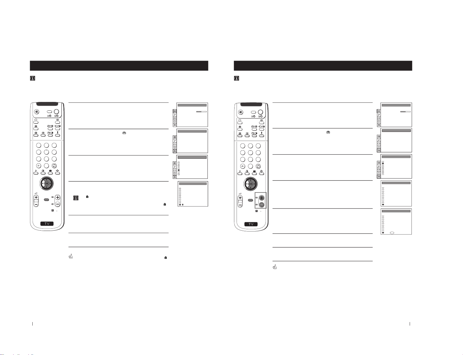
Locking Programmes
This feature enables you to prevent undesirable broadcasts appearing on the screen. We suggest you use this function to
prevent children from watching programmes you consider unsuitable.
1
Press the MENU button on the remote control to display the menu
on the screen.
2
Push the joystick to $ to select the
symbol, then push to z to
enter to the PRESET menu.
3
Push the joystick to $ or 4 to select Parental Lock, then push to z.
4
Push the joystick to $ or 4 to select the programme number with
the channel you wish to block, then press the OK button.
The
symbol appears before the programme position to
indicate this programme is now blocked.
To unblock the programme, press the OK button again. The
symbol disappears.
5
Repeat step 4 if you wish to block other channels.
6
Press the MENU button to exit and return to the normal TV screen.
When you select a blocked programme the screen appears in black, with
symbol.
S
RM
892
PROGR
MENU
1
4
7
2
5
8
0
3
6
9
VIDEO TV
Auto Programme
Manual Programme Preset
Further Programme Preset
AV Label Preset
Programme Sorting
Parental Lock
Language
Convergence
Digital Subtitles Off
PRESET
Auto Programme
Manual Programme Preset
Further Programme Preset
AV Label Preset
Programme Sorting
Parental Lock
Language
Convergence
Digital Subtitles Off
PRESET
I
DIG
I
DIG
I
I
DIG
DIG
DIG
DIG
0
1
2
3
4
5
6
7
8
9
PROG
MV-CH
TVE-1
TVE-2
ANT-3
TELE 5
C PLUS
- - - - -
- - - - CNN -
- - - - -
C 40
C 41
C 31
C 34
C 27
C 47
C 44
C 23
C 35
C 28
SYS CHAN LABEL
PARENTAL LOCK
PICTURE CONTROL
Personal
Wide
Composite
Picture Mode
Contrast
Reset
Format
Digital Signal
19
S
RM
892
PROGR
MENU
1
4
7
2
5
8
0
3
6
9
VIDEO TV
Menu System
Menu System
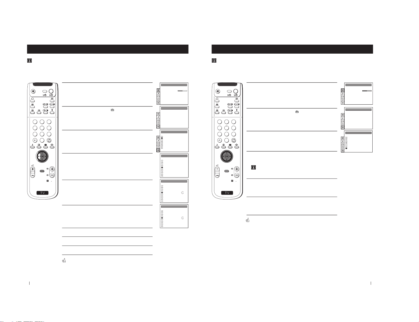
Skipping Programme positions
You can programme this projection TV to skip any unwanted programme numbers when they are selected with the
PROGR +/- buttons. To cancel this function afterwards, proceed in the same way as described below by selecting the
appropriate TV system (I or DIG) instead of "- - -" in step 5.
1
Press the MENU button on the remote control to display the menu
on the screen.
2
Push the joystick to $ to select the
symbol, then push to z to
enter to the PRESET menu.
3
Push the joystick to $ or 4 to select Manual Programme Preset,
then push to z.
4
Push the joystick to $ or 4 to select the programme position you
want to skip, then push to z to enter to the SYS column.
5
Push the joystick to $ to select “- - -”, then press the OK button to
store.
6
Repeat steps 4 and 5 to skip other unused programme positions.
7
Press the MENU button to exit and return to the normal TV screen.
When changing channels (TV Broadcasts) with the PROGR +/- buttons,
the skipped programme positions do not appear. You can, however, still
select them using the number buttons.
Auto Programme
Manual Programme Preset
Further Programme Preset
AV Label Preset
Programme Sorting
Parental Lock
Language
Convergence
Digital Subtitles Off
PRESET
Auto Programme
Manual Programme Preset
Further Programme Preset
AV Label Preset
Programme Sorting
Parental Lock
Language
Convergence
Digital Subtitles Off
PRESET
0
1
2
3
4
5
6
7
8
9
PROG
MANUAL PROGRAMME PRESET
CHAN
MV-CH
TVE-1
TVE-2
ANT-3
TELE 5
C PLUS
- - - - -
- - - - CNN BBC-TWO
LABEL
C 40
C 41
C 31
C 34
C 27
C 47
C 44
C 23
C 23
C 23
I
DIG
I
DIG
I
I
DIG
DIG
DIG
DIG
SYS
06
02
03
04
05
01
SERV
0
1
2
3
4
5
6
7
8
9
PROG
MANUAL PROGRAMME PRESET
CHAN
MV-CH
TVE-1
TVE-2
ANT-3
TELE 5
C PLUS
- - - - -
- - - - CNN BBC-TWO
LABEL
C 40
C 41
C 31
C 34
C 27
C 47
C 44
C 23
C 23
C 23
I
DIG
I
DIG
I
I
DIG
DIG
DIG
- - -
SYS
06
02
03
04
05
01
SERV
PICTURE CONTROL
Personal
Wide
Composite
Picture Mode
Contrast
Reset
Format
Digital Signal
– 17 –
20
S
RM
892
PROGR
MENU
1
4
7
2
5
8
0
3
6
9
VIDEO TV
Menu System
Menu System
Labelling a channel (analogue channels only)
Names for analogue channels (TV Broadcasts) are usually taken automatically from Teletext if available. You can however
name a channel or an input video source using up to five characters (letters or numbers). Using this function, you can
easily identify which channel (TV Broadcasts) or video source you are watching.
1
Press the MENU button on the remote control to display the menu
on the screen.
2
Push the joystick to $ to select the
symbol, then push to z to
enter to the PRESET menu.
3
Push the joystick to $ or 4 to select Manual Programme Preset,
then push to z.
4
Push the joystick to $ or 4 to select the programme number with
the analogue channel you wish to name.
5
Push the joystick to z repeatedly until the first element of the
LABEL column is highlighted.
6
Push the joystick to $ or 4 to select a letter or number (select
“-” for
a blank), then push to z to confirm this character. Select the other
four characters in the same way.
7
After selecting all the characters, press the OK button.
8
Repeat steps 4 to 7 if you wish to label other channels.
9
Press the MENU button to exit and return to the normal TV screen.
When you select a named channel, the name appears for a few seconds on
the screen.
Auto Programme
Manual Programme Preset
Further Programme Preset
AV Label Preset
Programme Sorting
Parental Lock
Language
Convergence
Digital Subtitles Off
PRESET
Auto Programme
Manual Programme Preset
Further Programme Preset
AV Label Preset
Programme Sorting
Parental Lock
Language
Convergence
Digital Subtitles Off
PRESET
PROG
MANUAL PROGRAMME PRESET
0
1
2
3
4
5
6
7
8
9
- - - - -
- - - - -
- - - - -
- - - - -
- - - - -
- - - - -
- - - - -
- - - - -
- - - - -
- - - - -
LABELCHAN
C 40
C 41
C 31
C 34
C 27
C 47
C 44
C 23
C 23
C 23
I
DIG
I
DIG
I
I
DIG
DIG
DIG
DIG
SYS
06
02
03
04
05
01
SERV
PROG
MANUAL PROGRAMME PRESET
0
1
2
3
4
5
6
7
8
9
LABEL
- - - - -
- - - - -
- - - - -
- - - - -
- - - - -
- - - - -
- - - - -
- - - - -
- - - - -
- - - - -
CHAN
C 40
C 41
C 31
C 34
C 27
C 47
C 44
C 23
C 23
C 23
I
DIG
I
DIG
I
I
DIG
DIG
DIG
DIG
SYS
06
02
03
04
05
01
SERV
PROG
MANUAL PROGRAMME PRESET
0
1
2
3
4
5
6
7
8
9
LABEL
- - - - -
- - - - -
- - - - -
- - - - A- - - -
- - - - -
- - - - -
- - - - -
- - - - -
- - - - -
CHAN
C 40
C 41
C 31
C 34
C 27
C 47
C 44
C 23
C 23
C 23
I
DIG
I
DIG
I
I
DIG
DIG
DIG
DIG
SYS
06
02
03
04
05
01
SERV
PICTURE CONTROL
Personal
Wide
Composite
Picture Mode
Contrast
Reset
Format
Digital Signal
21
Menu System
Displaying subtitles for digital channels
With this feature you can view subtitles (if available) on the TV screen when watching digital channels. When watching
analogue channels you can view subtitles via teletext.
1
Press the MENU button on the remote control to display the menu
on the screen.
2
Push the joystick to $ to select the
symbol, then push to z to
enter to the PRESET menu.
3
Push the joystick to $ or 4 to select Digital Subtitles, then push to
z .
4
Push the joystick to Z or z to select the language in which you wish
the subtitles to appear. You can choose from English, Welsh or
Gaelic.
When you wish to cancel subtitles, set to Off.
5
Press the OK button to confirm your selection.
6
Press the MENU button to exit and return to the normal TV screen.
When you select a digital channel which broadcasts subtitles, the subtitles
appear on the bottom of the screen in the chosen language.
Menu System
S
RM
892
PROGR
MENU
1
4
7
2
5
8
0
3
6
9
VIDEO TV
PICTURE CONTROL
Personal
Wide
Composite
Picture Mode
Contrast
Reset
Format
Digital Signal
Auto Programme
Manual Programme Preset
Further Programme Preset
AV Label Preset
Programme Sorting
Parental Lock
Language
Convergence
Digital Subtitles Off
PRESET
Auto Programme
Manual Programme Preset
Further Programme Preset
AV Label Preset
Programme Sorting
Parental Lock
Language
Convergence
Digital Subtitles Off
PRESET
– 18 –
22
S
RM
892
PROGR
MENU
1
4
7
2
5
8
0
3
6
9
VIDEO TV
Menu System
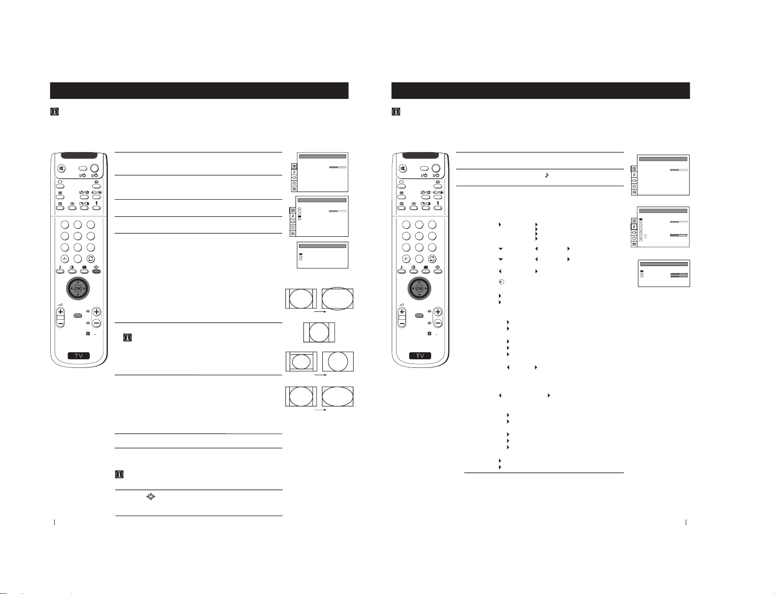
Selecting the Output Source for the Euro AV connectors
1
Press the MENU button on the remote control to display the menu
on the screen.
2
Push the joystick to $ to select the
symbol, then push to z
button to enter to the VIDEO CONNECTION menu screen.
3
Push the joystick to $ or 4 button to highlight:
TV Screen (input source for the TV screen) or
Output (output source available for :2 and :3 Euro AV
connectors).
Push the joystick to z to confirm.
4
Push the joystick to Z or z repeteadly to select the desired source:
TV Screen TV, AV1, RGB, AV2, YC2 or AV3
Output TV, AV1, AV2, YC2, AV3 or AUTO
Then press the OK button to confirm.
If you select "AUTO", the output signal will always be the same
one that is displayed on the screen.
If you have connected a decoder, please remember to change
back the Output to "TV" for correct unscrambling.
5
Press the MENU button to exit and return to the normal TV screen.
The selected signal is available for your optional equipment connected to
the appropriate Euro AV connector.
Menu System
Using this function you can record on your VCR any signal coming from an external equipment connected to the Euro AV
connectors :2 or :3 placed on the rear of the projection TV.
In that case you have to select the output source as described below (if your VCR support Smartlink, this procedure is not
necessary).
PICTURE CONTROL
Personal
Wide
Composite
Picture Mode
Contrast
Reset
Format
Digital Signal
VIDEO CONNECTION
[TV - - - - - - -]
[AV1 - - - - - - -]
TV Screen
Output
TV
AV1
23
Menu System
Labelling of Input Sources
1
Press the MENU button on the remote control to display the menu
on the screen.
2
Push the joystick to $ to select the
symbol, then push to z to
enter to the PRESET menu screen.
3
Push the joystick to $ or 4 to select AV Label Preset, then push
to z.
4
Push the joystick to $ or 4 to select the input source you wish to
name (eg AV2), then push to z to highlight the first element of the
LABEL column.
5
Push the joystick to $ or 4 to select a letter or number (select
“-” for
a blank) then push to z to confirm this character. Select the other
four characters in the same way.
6
After selecting all the characters, press the OK button.
7
Repeat steps 4 to 6 if you wish to label other input sources.
8
Press the MENU button to exit and return to the normal TV screen.
Whenever the equipment with the labeled input is selected for use, the
name appears for a few seconds on the screen.
Menu System
This function enables you to designate a name to the optional equipment you have connected to the sockets of this
projection TV. This name can be up to 5 characters (letters or numbers).
S
RM
892
PROGR
MENU
1
4
7
2
5
8
0
3
6
9
VIDEO TV
PICTURE CONTROL
Personal
Wide
Composite
Picture Mode
Contrast
Reset
Format
Digital Signal
Auto Programme
Manual Programme Preset
Further Programme Preset
AV Label Preset
Programme Sorting
Parental Lock
Language
Convergence
PRESET
Auto Programme
Manual Programme Preset
Further Programme Preset
AV Label Preset
Programme Sorting
Parental Lock
Language
Convergence
PRESET
AV LABEL PRESET
AV1
RGB
AV2
YC2
AV3
INPUT LABEL
- - - - -
- - - - -
- - - - -
- - - - -
- - - - -
AV LABEL PRESET
AV1
RGB
AV2
YC2
AV3
INPUT LABEL
- - - - -
- - - - A- - - -
- - - - -
- - - - -
– 19 –
24
Displaying the EPG
1
Press the
button on the remote control to display the electronic
programme guide (EPG) on the screen.
You may see the message "EPG INFORMATION IS
TEMPORARILY UNAVAILABLE" whilst waiting for the EPG
to appear on screen.
2
Push the joystick to $, 4, Z or z to move the on-screen cursor
around the guide.
3
Press the
button again to exit and return to the normal TV
screen.
Viewing Information on the EPG
You can alter the type of information presented on the EPG by
changing data in each of the EPG columns. You can for example
display information for all sports programmes being shown
tomorrow from 5.00pm onward.
1
Press the
button on the remote control to display the EPG on the
TV screen.
2
Push the joystick to Z or z to highlight the date column, then push
to 4 or $ to select your chosen date.
3
Push the joystick to Z or z to highlight the time column, then push
to 4 or $ to select your chosen time.
4
Press the OK button. The EPG will display programme information
according to the date and time you selected.
5
Push the joystick to z to highlight programme type column, then
push to 4 or $ to select
Films,
News,
Lifestyle,
Sport,
Children Programmes,
Entertainment or
Education.
6
Push the joystick to Z or z to update the programme information
accordingly. If you selected tomorrow's date, 17:00 and
Sport,
you should now be able to view all the sports programmes being
shown tomorrow from 5.00 pm onwards.
7
Press the
button to exit and return to the normal TV screen.
Electronic Programme Guide (EPG)
Displaying and Viewing EPG
The electronic Programme Guide (EPG) is a guide which provides programme information for all digital channels
supporting EPG. When looking for information you can search by theme (sports, art, etc.), date or time (e.g. broadcasts
between 8 and 9 pm). When you have found a programme you can go directly to this programme, use the timer to remind
you of it or preset your VCR with Smartlink.
Electronic Programme Guide (EPG)
S
RM
892
PROGR
MENU
1
4
7
2
5
8
0
3
6
9
VIDEO TV
22
Tues
23
Wed
24
Thu
25
26
Sat
27
Sun
28
Mon
6
9
12
16:00
18
21
24
3
Tue 22 DEC
15:20:40
Press O.K. to view data for all available channels
Press to return to programme list.
2
4
5
1
3
1
1
3
4
BBC 2
International Cricket – – –
Channel 4
Racing From Epsom –– –
C 5
Film: Rachel And The –– –
BBC 1
The Little Pet Shop –– –
HTV
Bernards Watch
BBC 1
Boger And Badger N
BBC 1
Bailey Kippers Prov S – – –
HTV
Sabrina The Teenage –– –
BBC 1
Vets in Practice
12
12h
13:35 - 18:25
14:00 - 16:30
15:30 - 17:10
15:50 - 16:00
15:55 - 16:15
16:00 - 16:15
16:15 - 16:35
16:15 - 16:40
16:30 - 17:30
ALL
12
- 1h
NOW
25
Electronic Programme Guide (EPG)
Recording Programmes using EPG
1
Press the
button on the remote control to display the programme
guide on the screen.
2
Push the joystick to Z or z to highlight the programme column,
then push to 4 or $ to select your desired programme.
3
Press the OK button. If the programme is currently being broadcast,
it will be displayed on your TV. If not, the TIMER menu will be
displayed on the TV screen.
4
At the bottom of the timer page you can see the symbols
(back to EPG), (to record a programme) or (to set the
programme to switch on automatically).
5
Push the joystick to Z or z to select one of these symbols then press
the OK button to confirm your selection. The EPG appears on
screen with the relevant icon appearing next to the programme you
selected in step 2.
6
If you wish to cancel a recording, select the relevant programme and
press the OK button. A menu is displayed on screen requesting you
to select Return if you wish to continue to record the programme or
Delete if you wish to cancel the recording request.
7
After making your selection, press the OK button to confirm. The
record icon disappears from the EPG if Delete was selected in step
6.
8
If you have finished viewing programmes on your TV, press the TV
button before the timer recording starts to leave your projection
TV in standby mode for the timer settings to be activated. If,
however, you wish to continue watching other programmes after
setting the timer, you can do so by changing programmes in the
normal way. If you are watching another programme when the
timer is due to start, a display will appear on screen advising you
that, if you change channels, you automatically cancel the
recording.
9
If you do not wish to cancel or view the recording, press the TV
button whilst one of the displays are still on screen to leave your
projection TV in standby mode. The standby indicator on the front
of the set will flash to show that the timer record operation is active.
If, however, you choose to change programmes, you automatically
cancel the recording.
Notes: • If your video recorder (VCR) is not Smartlink-compatible,
you will need to set your VCR to switch on and off
automatically after setting the timer on the EPG.
• If you want to change channel once a digital programme has
started recording, select the channel by using the remote
control buttons as normal. The message "STOP
RECORDING" will be displayed on screen. Either do nothing
to allow the recording to continue or select the required
channel once more while the message is still displayed on
screen. The recording will then be cancelled.
Electronic Programme Guide (EPG)
S
RM
892
PROGR
MENU
1
4
7
2
5
8
0
3
6
9
VIDEO TV
Return
Event Rec
Wake up
22
Tues
23
Wed
24
Thu
25
26
Sat
27
Sun
28
Mon
6
9
12
17:00
18
21
24
3
Tue 22 DEC
15:20:40
Press O.K. to view data for all available channels
Press to return to programme list.
2
4
5
1
3
1
1
3
4
BBC 2
International Cricket – – –
Channel 4
Racing From Epsom –– –
C 5
International Boxing – – –
BBC 1
Tennis –– –
HTV
Motor Cross
BBC 2
International Athletics – – –
BBC 1
Speedway – – –
HTV
Swimming–– –
BBC 1
Match of the day
12
12h
13:35 - 18:25
14:00 - 16:30
15:30 - 17:10
15:45 - 16:45
15:55 - 16:25
19:00 - 21:15
16:15 - 16:40
16:15 - 16:40
16:30 - 17:30
ALL
12
- 1h
NOW
Tue 22 DEC
15:20:40
12
Vets in Practice
10 British Broadcasting Opera 16:30 - 17:30 Tue 22 Dec
Documentary series which follows veterinary graduates
as they embark on their careers.
Julie Richards has to deal with a terrier with behavioural
problems and Steve Leonard encounters problems
when he has to treat a golden labrador.
Continues on Friday
Return Event Rec
Wake Up
Tue 22 DEC
15:20:40
12
Timer Recording Event will begin soon.
During this event you cannot select the
channel
– 20 –
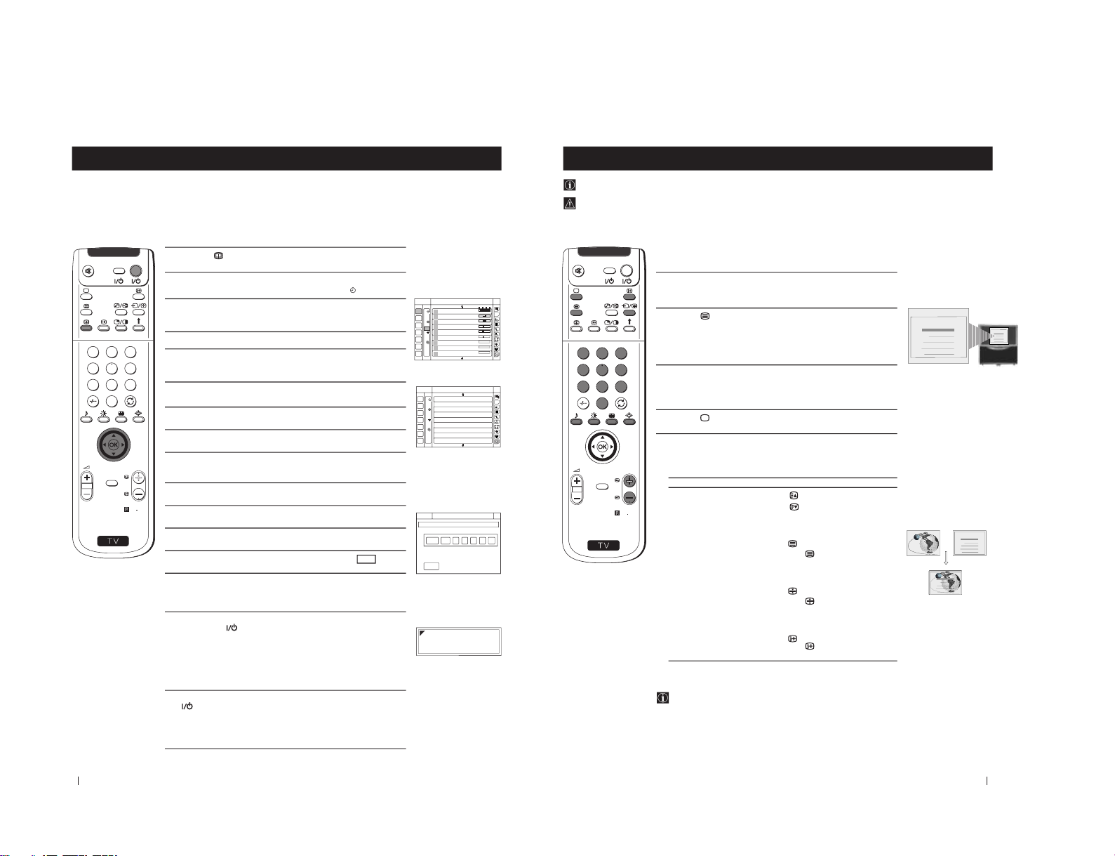
26
S
RM
892
PROGR
MENU
1
4
7
2
5
8
0
3
6
9
VIDEO TV
Electronic Programme Guide (EPG)
Setting The Manual Timer
11
Press the
button on the remote control to display the EPG on
the screen.
12
Push the joystick to Z or z to highlight the programme type
column, then push to $ to select the timer symbol
.
13
Press the OK button to display a screen of 9 programme slots, each
one indicating that it is either free for programming, or that it has
a programme already stored in it.
14
Push the joystick to Z to enter the programme column.
15
Push the joystick to $ or 4 to select a free row then press the OK
button to display the Set Timer screen. This screen asks you to
confirm the date, programme number, start time and end time.
16
Push the joystick to 4 to select the date area then push to 4 or $ to
select the date.
17
Push the joystick to z to confirm the date then push to $ or 4 to
select the month.
18
Push the joystick to z to confirm the month and to enter the start
time.
19
Push the joystick to 4 or $ to select the time when you want the
timer to switch on, preferably several minutes before you set your
video recorder to start recording.
10
Push the joystick to z to confirm the entry and to enter the switchoff time.
11
Push the joystick to 4 or $ to select the time you want the timer to
switch off, preferably after your video has stopped recording.
12
Push the joystick to z to confirm the entry and to enter the
programme number.
13
Press the OK button to save the settings, then select and
press OK button to return to the Manual Timer Setup menu.
14
Select another available slot if you wish to record a further
programme. Otherwise, push the joystick to z to enter the
programme type column, then press the OK button to return to
the EPG.
15
If you have finished viewing programmes on your projection TV,
press the TV
button before the timer recording starts to leave
your projection TV in standby mode for the timer settings to be
activated. If, however, you wish to continue watching other
programmes after setting a timer, you can do so by changing
programmes in the normal way. If you are watching another
programme when the timer is due to start a display will appear on
screen advising you that, if you change channels now, you
automatically cancel the recording.
16
If you do not wish to cancel or view the recording, press the TV
button whilst the display is still on screen to leave your
projection TV in standby mode. The standby indicator on the front
of the set will flash to show that the timer record operation is
active. If, however, you choose to change programmes, you
automatically cancel the recording.
Electronic Programme Guide (EPG)
Return
22
Tues
23
Wed
24
Thu
25
26
Sat
27
Sun
28
Mon
6
9
12
18:00
18
21
24
3
Tue 22 DEC
15:20:40
Press O.K. to view data for all available channels
Press to return to programme list.
2
4
5
1
3
1
1
3
4
BBC 2
International Cricket – – –
Channel 4
Racing From Epsom –– –
C 5
Film: Rachel And The –– –
BBC 1
The Little Pet Shop –– –
HTV
Bernards Watch
BBC 1
Boger And Badger N
BBC 1
Bailey Kippers Prov S – – –
HTV
Sabrina The Teenage –– –
BBC 1
Vets in Practice
12
12h
13:35 - 18:25
14:00 - 16:30
15:30 - 17:10
15:50 - 16:00
15:55 - 16:15
16:00 - 16:15
16:15 - 16:35
16:15 - 16:40
16:30 - 17:30
ALL
12
- 1h
NOW
22
Tues
23
Wed
24
Thu
25
26
Sat
27
Sun
28
Mon
6
9
12
18
21
24
3
Tue 22 DEC
15:20:40
Timer event list. Press OK to view
12
ALL
12
Manual Timer Setup
Manual Timer Setup
Manual Timer Setup
Manual Timer Setup
Manual Timer Setup
Manual Timer Setup
Manual Timer Setup
Manual Timer Setup
Manual Timer Setup
Manual Timer Setup
Tue 22 DEC
15:20:40
12
Manual Timer Setup
Return
Tue 22 DEC
15:20:40
12
THU 24
DEC
16
00
:
:
DATE START STOP PROG No
Timer Recording Event will begin soon.
During this event you cannot select the
channel
27
S
RM
892
PROGR
MENU
1
4
7
2
5
8
0
3
6
9
VIDEO TV
Teletext
Teletext
Viewing Teletext (analogue channels only)
Using Fastext
Fastext lets you access pages with one button stroke.
When Fastext is broadcast, a colour coded menu appears at the
bottom of the teletext page. Press the colour button (red, green,
yellow or blue) on the remote control to access the corresponding
page.
Index
TELETEXT
Programme
News
Sport
Weather
25
153
101
98
Index
TELETEXTTELETEXT
Programme
News
Sport
Weather
25
153
101
98
Index
TELETEXTTELETEXT
Programme
News
Sport
Weather
25
153
101
98
Index
TELETEXTTELETEXT
Programme
News
Sport
Weather
25
153
101
98
Selecting Teletext
1
Select the TV channel which carries the teletext service you wish to
view.
2
Press the
button on the remote control to switch on the teletext.
3
Input three digits for the page number, using the numbered buttons
on the remote control. (if you have made a mistake, type in any
three digits and then, re-enter the correct page number).
4
Press the
button to switch off teletext.
Using other Teletext functions
TO PRESS THE BUTTON
Access the next or preceding page
for next page or
for the preceding page
Superimpose teletext on to the TV
Press
again to cancel teletext
mode.
Freeze a teletext page
Press
again to cancel the
freeze.
Reveal concealed information
(e.g.: answer to a quiz) Press
again to cancel.
Teletext is an information service transmitted by most TV stations.
Make sure to use a TV channel with a strong signal, otherwise teletext errors may occur.
– 21 –
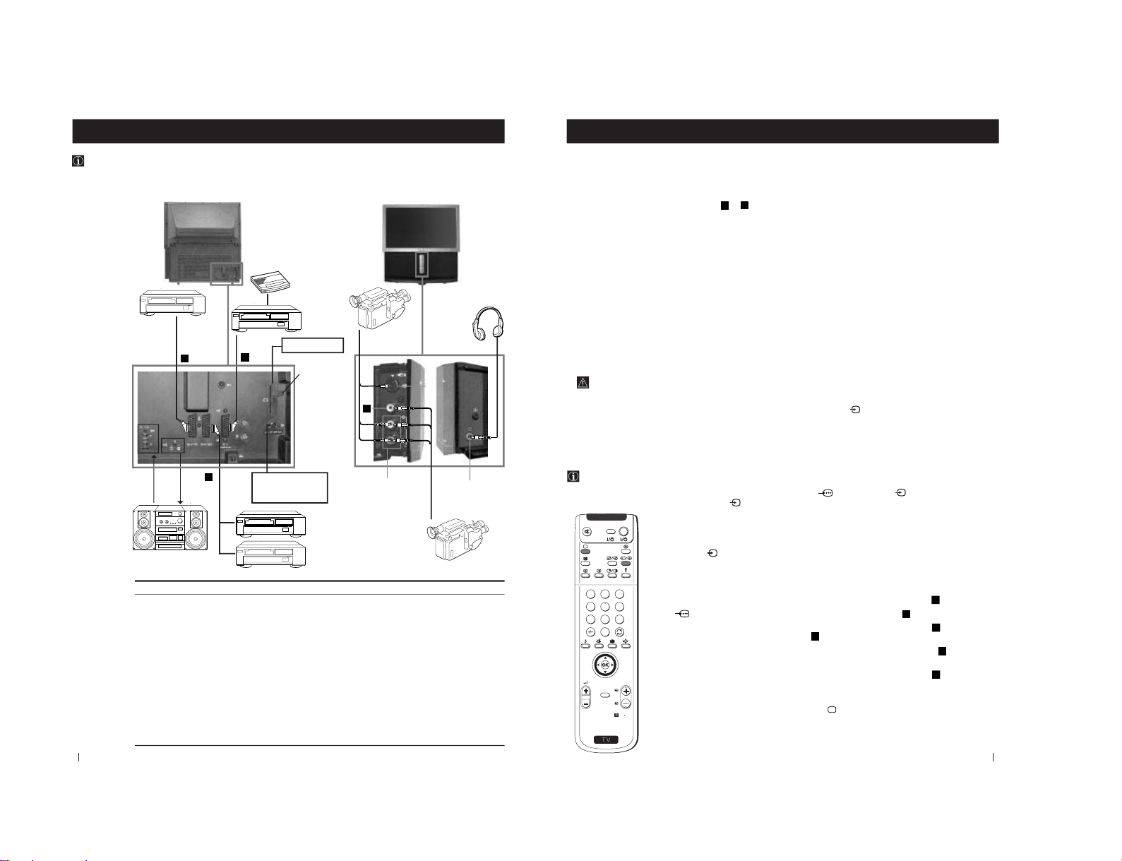
28
Available output signal
No outputs
Audio signal
Video/audio from TV tuner
Video/audio from selected source
Video/audio from selected source (the same output source as
the :2/ q 2 connector)
No output
No output
No output
Audio signal to headphones
To avoid
picture
distortion:
• Do not
connect
equipment to
F and G
connectors at
the same
time.
• Do not
connect any
equipment on
the front
connectors
together with
D connector.
If you want to
record signals
from any
external
equipment:
connect the
recording
device to the E
socket.
Using the following instructions, you can connect a wide range of optional equipment to your projection TV.
Optional Connections
Connecting Optional Equipment
Optional Connections
8mm/Hi8
camcorder
S.VHS/Hi8
camcorder
G
F
HI
A
B
C
D
E
F
Acceptable input signal
Centre speaker input
Set “Speaker” on the SOUND
CONTROL menu to
“Centre in”.
No inputs
Audio/video and RGB signal
Audio/video and S video signal
Audio/video signal
S Video signal
Video signal
Audio signal
No input
G
H
I
VCR
Hi-Fi
Decoder
VCR
DVD
E
D
C
A
B
DVD
PCMCIA socket
MODEM connection
(connect to the
Modem)
(unscrew and
remove the
cover. After
inserting the
PCMCIA card,
screw the cover
again)
Rear of projection TV Front of projection TV
29
Optional Connections
Using Optional Equipment
Optional Connections
Additional Information when connecting equipment
Connecting a VCR
We recommend you connect your VCR to the
D
or
E
socket using a scart lead. If you do not have a scart lead, use
the “Manually Tuning the TV
” section of this instruction manual to tune in the VCR signal to TV programme
number “0”. Also refer to your VCR instruction manual to get the VCR test signal.
If your video supports Smartlink please refer the "Smartlink" section of this instruction manual.
Connecting to External Audio Equipment
1 To listen to the audio of your projection TV on the Hi-Fi equipment:
Plug in your Hi-Fi equipment to the B sockets on the rear of the projection TV if you wish to amplify the audio
output from the TV.
The output level from B sockets can be varied by adjusting the volume of the headphones. Refer to the
“Adjusting the sound
” section of this instruction manual to adjust the volume of the headphones.
2 To listen to the Dolby Prologic system sound on the projection TV speakers:
Plug in your Dolby Prologic system decoder amplifier to the A socket on the rear of the projection TV if you
wish to listen to the audio output from your equipment on the projection TV speaker. If you have a Dolby
amplifier, connect the centre output from your amplifier to the A socket to use the projection TV as a centre
speaker. Refer to the
“Adjusting the Sound
” section of this instruction manual and set the option
“Speaker” to
“Centre in”.
Remember that the maximum input level of this input is 30 W. Be careful never to over this limit.
For mono equipment
Connect the phono plug to the L/G/S/I socket on the front of the TV and select the
2 input signal using the
instructions on this page below. Finally, refer to the
“Adjusting the Sound
” section of this manual and select
“A” on
the sound menu screen.
Select and View the Input Signal
In order to get the input signal of a connected equipment onto the TV screen, you need to select the symbol of
the connector to which you have connected the device.
e. g. : Your VCR is connected to the connector with the symbol Y1/
. Press the button
on the remote
control repeatedly until you see the symbol
1 on the screen.
2
S
RM
892
PROGR
MENU
1
4
7
2
5
8
0
3
6
9
VIDEO TV
1
Connect your equipment to the designated projection TV socket, as it is indicated on the
previous page.
2
Press
the
button repeatedly on your remote control until the correct input symbol
appears on the screen.
Symbol Input signals
k
• Audio/video input signal through the Euro AV connector
C
• RGB input signal through the Euro AV connector
C
K
• Audio/Video input signal through the Euro AV connector
D
or the
phono sockets H and
G
.
q
• Audio/S Video input signal through the Euro AV connector
D
or the
sockets H and F.
K
• Audio/Video input signal through the Euro AV connector
E
3
Switch on the connected equipment.
4
To return to the normal TV picture, press the
button on the remote control.
3
– 22 –
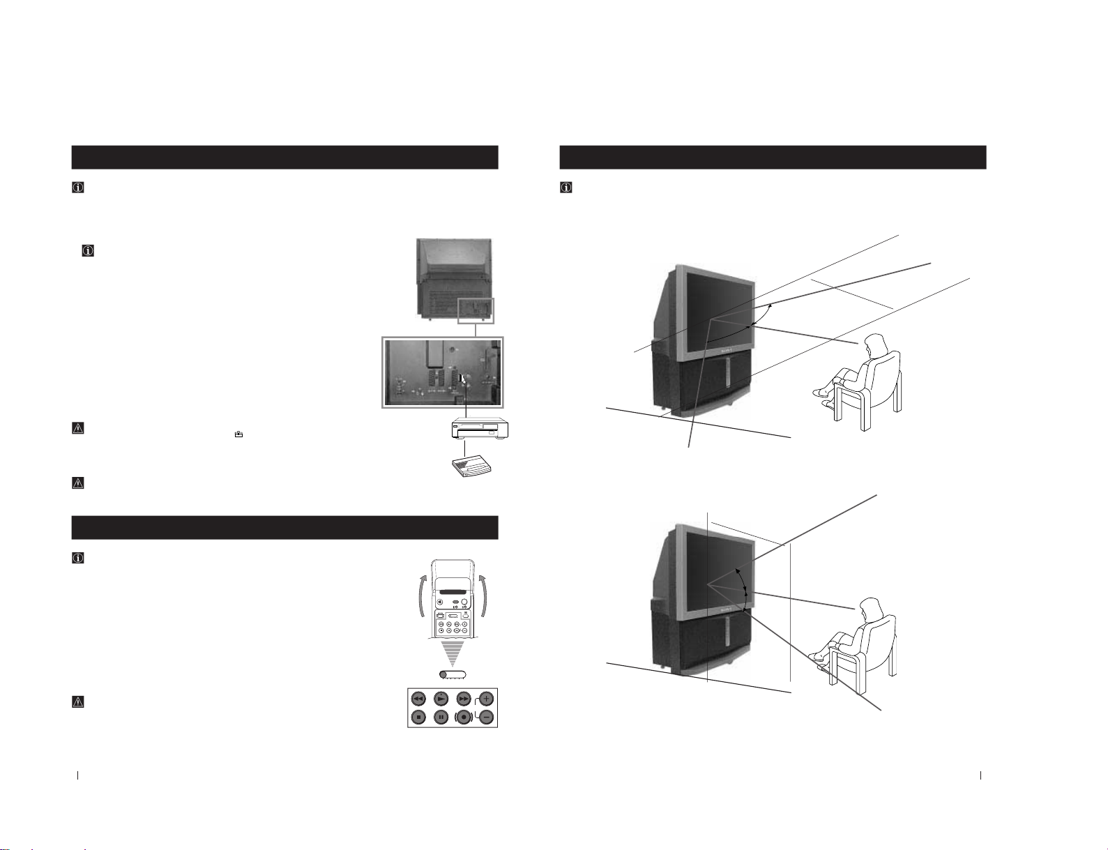
30
Optional Connections
Smartlink
Smartlink is a direct link between your projection TV set and a VCR.
For Smartlink you need:
• A VCR which supports Smartlink, NextView Link, Easy Link or Megalogic.
Megalogic is a trademark of Grundig Corporation.
EasyLink is a trademark of Philips Corporation.
• A fully-wired 21 pin SCART cable to connect your VCR to the Euro AV connector :3
(SMARTLINK)on the rear of the Projection TV.
The features of Smartlink are:
• Tuning information such as the channel overview are downloaded from the projection
TV set to the VCR.
• Direct projection TV recording: While watching TV you need to press just one button on
the VCR to record this programme.
• Projection TV in standby mode: Press the "Play z" button on your VCR to switch the TV
automatically on.
If you have connected a decoder to a VCR which supports Smartlink feature, select
the menu Further Programme Preset in the
(PRESET) menu and select DECODER
AV
3
to each codified channel. For more details, please refer to the section "Using the
Further Programme Preset function" of this instruction manual.
For more information on Smartlink, please refer to the Instruction Manual of your
VCR.
Optional Connections
VCR
Remote Control of other Sony Equipment
Using the buttons underneath the cover of the remote control you can
control other Sony equipment.
1
Open the cover of the Remote Control.
2
Set the selector VTR 1234 DVD according to the equipment you want to control:
VTR 1 Beta VCR
VTR 2 8 mm VCR
VTR 3 VHS VCR
VTR 4 Digital Video (DCR-VX 1000/9000 E, VHR-1000)
DVD Digital Video Disk
3
Use the buttons underneath the cover on the remote control to operate the
equipment.
• If your video equipment has a COMMAND MODE selector, set this
selector to the same position as the VTR 1234 DVD selector on the
TV Remote Control.
• If the equipment does not have a certain function, the corresponding
button on the remote control does not work.
Decoder
VIDEO TV
VTR 1 2 3 4 DVD
CH
CH
VTR 1 2 3 4 DVD
Rear of projection TV
31
Additional Information
Optimum Viewing Area
For the best picture quality, try to position the projection TV so that you can view the screen from within the areas
shown below.
Additional Information
Horizontal viewing area
Vertical viewing area
(Optimum viewing position)
60˚
60˚
1.9 m
(Minimum optimum
distance)
1.9m
(Minimum optimum
distance)
(Optimum viewing position)
4
4
4
4
20˚
20˚
– 23 –
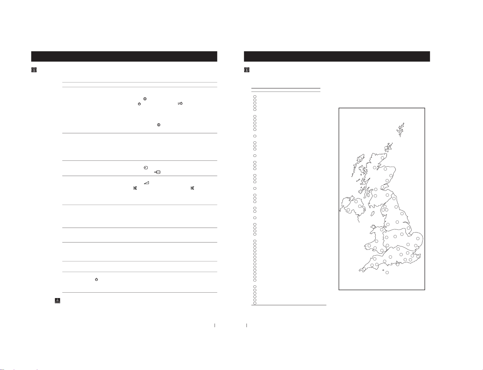
33
Additional Information
Troubleshooting
Here are some simple solutions to the problems which may affect the picture and sound.
Problem Solution
No picture (screen is dark), no sound
• Plug the projection TV in.
• Press the
button on the front of the projection TV.
• If the
indicator
is on, press TV
button or a
programme number
button on the remote control.
• Check the aerial connection.
• Check that the selected video source is on.
• Turn the projection TV off for 3 or 4 seconds and then turn it
on again using the
button on the front of the projection
TV.
Poor or no picture (screen is dark),
• Using the MENU system, select the Picture Adjustment
but good sound display.
Adjust the brightness, picture and colour balance levels.
• From the Picture Adjustment display select Reset to return
to the factory settings.
Poor picture quality when watching a
• Press the
button repeatedly on the remote control until
RGB video source. the RGB symbol
is displayed on the screen.
Good picture, no sound
• Press the
+/– button on the remote control.
• If
is displayed on the screen, press the
button on the
remote control.
• Check that "Main" speaker is selected on the SOUND
CONTROL menu.
No colour on colour programmes
• Using the MENU system, select the Picture Adjustment
display. Adjust the colour balance.
• From the Picture Adjustment display select Reset to return
to the factory settings.
Distorted picture when changing
• Turn off any equipment connected to the 21 pin Euro
programmes or selecting teletext connector on the rear of the TV.
Noisy picture when viewing TV
• Adjust Fine Tuning (AFT) to obtain better picture reception.
channel For details, please refer to the section "Using the Further
Programme Preset function"
Remote control does not function
• Replace the batteries.
The standby indicator
on the TV • Contact your nearest Sony service centre.
flashes even though the EPG is not
programmed to record.
• If you continue to have these problems, have your TV serviced by qualified personnel.
• NEVER open the casing yourself.
Additional Information
34
Additional Information
Additional Information
Television Channel Number Guide for analogue channels
Only the main transmitters are listed. Information regarding the regional sub-relay channel numbers can be obtained by
contacting The BBC Engineering Information Dept., Telephone Number 020 7852 5040.
44
41
40
25
24
23
43
42
39
33
37
34
45
38
31
32
35
30
36
28
49
27
48
46
50
47
51
21
20
19
5
9
7
6
8
10
11
15
14
12
13
1
4
2
3
29
22
18
17
16
26
MAIN TRANSMITTERS BBC1 BBC2 ITV CH4 CH5
London & South East
Bluebell Hill 40 46 43 65
–
Crystal Palace 26 33 23 30
–
Dover 50 56 66 53 –
Heathfield 49 52 64 67
–
Oxford 57 63 60 53 49
South-West
Beacon Hill 57 63 60 53
–
Caradon Hill 22 28 25 32
–
Huntshaw Cross 55 62 59 65 67
Redruth 51 44 41 47 37
Stockland Hill 33 26 23 29
–
Channel Islands
Fremont Point 51 44 41 47
–
South
Hannington 39 45 42 66
–
Midhurst 61 55 58 68
–
Rowridge 31 24 27 21
–
West
Mendip 58 64 61 54 37
East
Sandy Heath 31 27 24 21 39
Sudbury 51 44 41 47
–
Tacolneston 62 55 59 65 52
Midlands (West)
Ridge Hill 22 28 25 32
–
Sutton Coldfield 46 40 43 50
–
The Wrekin 26 33 23 29
–
Midlands (East)
Waltham 58 64 61 54
–
Northern Ireland
Brougher Mountain 22 28 25 32
–
Divis 31 27 24 21 –
Limavady 55 62 59 65
–
North
Belmont 22 28 25 32 56
Emley Moor 44 51 47 41 37
North-West
Winter Hill 55 62 59 65 48
North-East
Bilsdale West Moor 33 26 29 23
–
Caldbeck 30 34 28 32 56
Chatton 39 45 49 42
–
Pontop Pike 58 64 61 54
–
Scotland
Angus 57 63 60 53 –
Black Hill 40 46 43 50 37
Sandale 22 67 –––
Caldbeck _ _ 28 32 56
Craigkelly 31 27 24 21 48
Darvel 33 26 23 29 –
Durris 22 28 25 32 67
Eitshal (Lewis) 33 26 23 29
–
Keelylang Hill 40 46 43 50
–
Knock More 33 26 23 29
–
Rosemarkie 39 45 49 42
–
Rumster Forest 31 27 24 21
–
Selkirk 55 62 59 65 52
Wales
Blaenplwyf 31 27 24 21 56
Carmel 57 63 60 53 –
Llanddona 57 63 60 53
–
Moel-y-Parc 52 45 49 42
–
Presely 46 40 43 50 37
Wenvoe 44 51 41 47
–
1
2
3
4
5
6
7
8
9
10
11
12
14
13
15
16
17
18
19
20
21
22
23
24
25
26
27
28
29
30
31
32
33
34
35
36
37
38
39
40
41
42
43
49
50
51
44
45
46
47
48
– 24 –
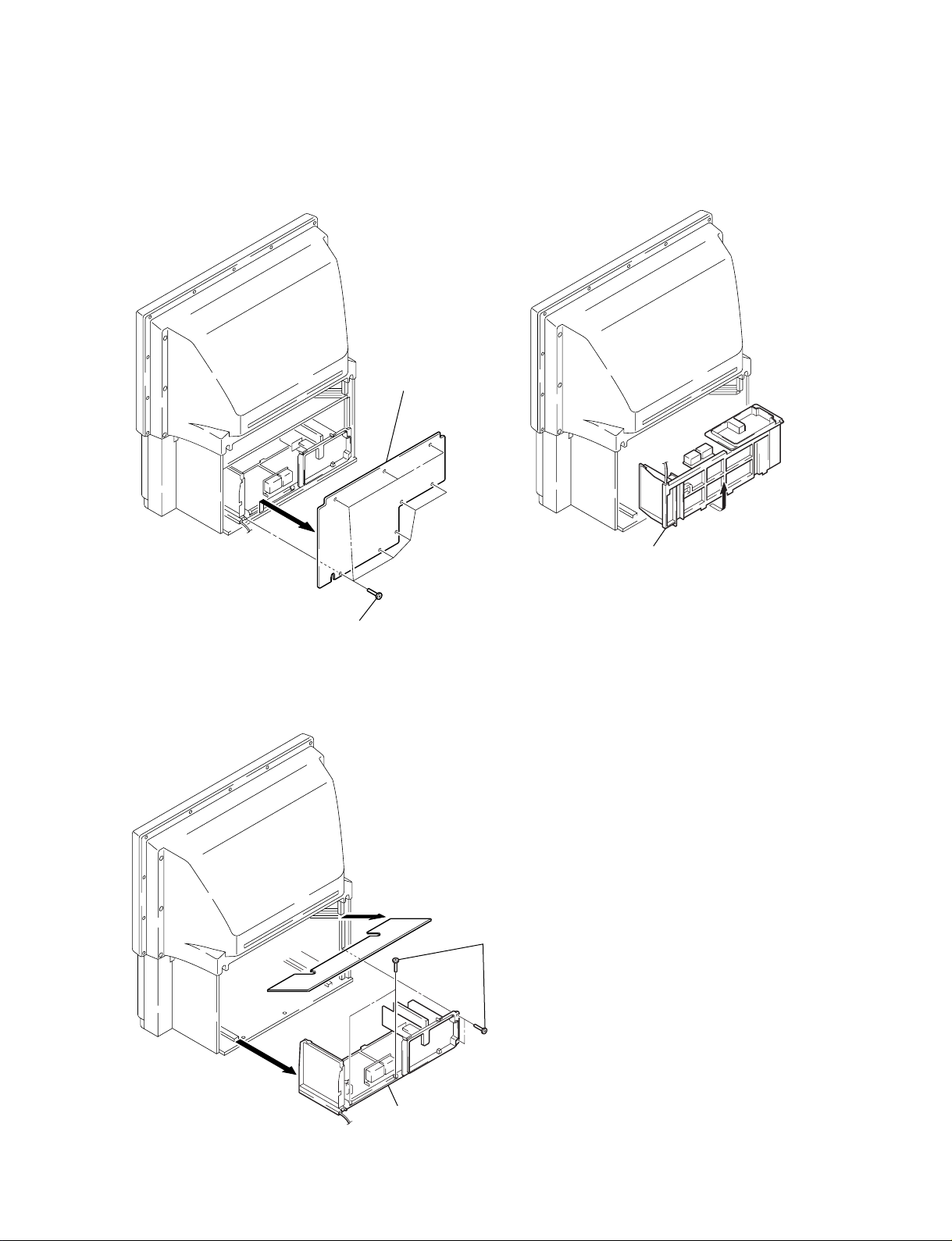
SECTION 3
DISASSEMBLY
KP-51DS1U
KRM-892
3-1. REAR BOARD REMOVAL
1 Eight screws
(Hexagon head)
3-3. SERVICE POSITION
2 Rear board
Main bracket block
3-2. MAIN BRACKET BLOCK REMOVAL
2 Main bracket block
1 Four screws
(Hexagon head)
– 25 –

KP-51DS1U
KRM-892
3-4. CONTROL PANEL BLOCK AND RESISTOR
ASSEMBLY (FOCUS PACK) REMOVAL
5 Control panel block
4 Two screws
(Hexagon head)
3 Front board
2 Nine screws
(Hexagon head)
1 Speaker grille assembly
3-5. BEZNET BLOCK REMOVAL
5 Beznet block
1 Eleven screws
3 Mirror cover block
6 Screw
(+BVTP4 × 16)
(+BVTP4 × 16)
7 Resistor assembly
(Focus Pack)
2 Four screws
(Hexagon head)
4 Four screws
(Hexagon head)
– 26 –
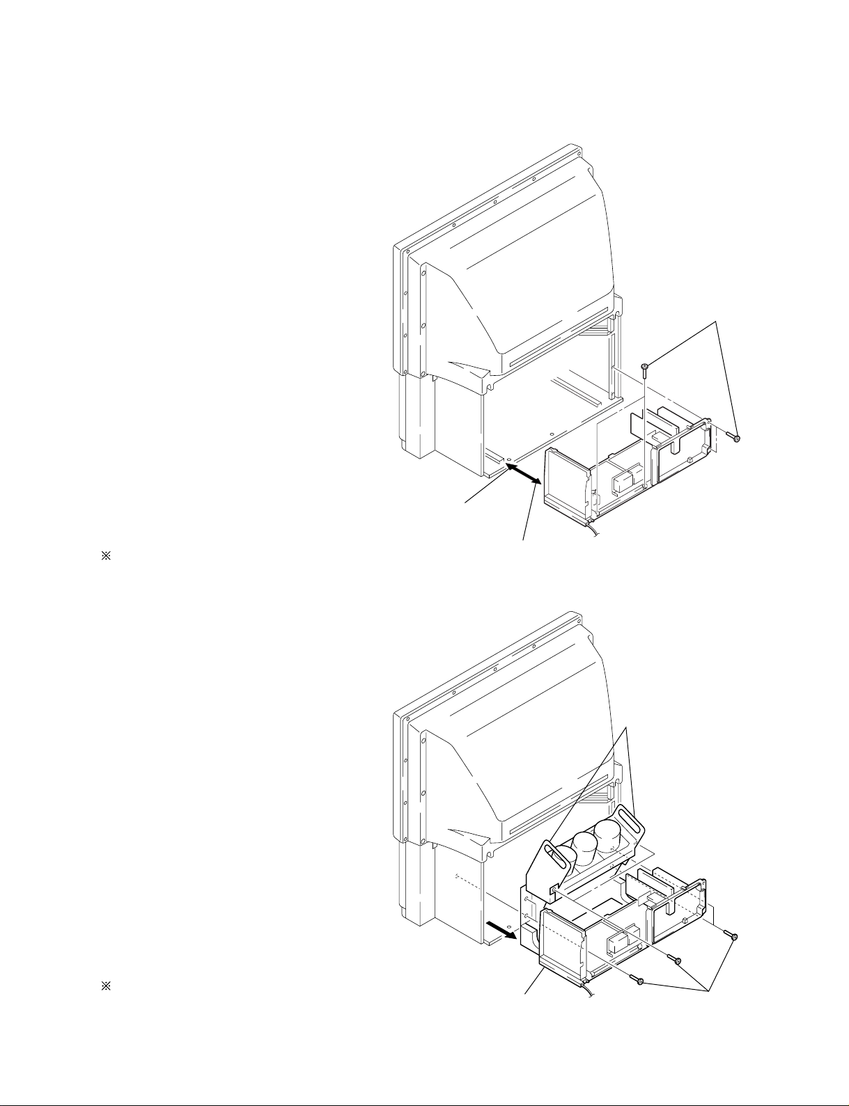
3-6. CHASSIS BLOCK REMOVAL
(1) MAIN BRACKET REMOVAL
KP-51DS1U
KRM-892
1 Four screws
(Hexagon head)
Pay particular attention to the wires of each Printed circuit
boards when puling out the main bracket.
(2) CHASSIS BLOCK REMOVAL
3 Set the main
bracket.
2 Pull the main bracket, and
remove each connections
on main bracket.
Handles
Pull out the chassis block by gripping the handles as shown in
the diagram.
At this time, pay particular attention to the components
removed in (1).
– 27 –
2 Pull out the chassis
block.
1 Six screws
(Hexagon head)
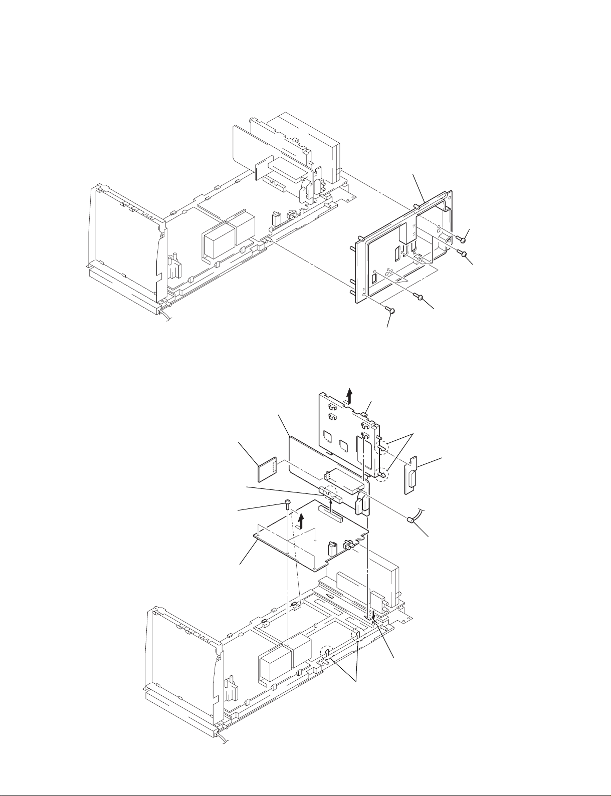
KP-51DS1U
KRM-892
3-7. TERMINAL BOARD REMOVAL
3 Terminal board
1 Two screws
(+BVTP 4 x 16)
2 Screw
(+BVTP 3 x 12)
1 Four screws
(+BVTP 4 x 16)
2 Two screws
(+BVTP 3 x 12)
3-8. A3, U, A AND D BOARDS REMOVAL
8 A board
1 A3 board
7 Claw
9 Four screws
(+BVTP 3 x 12)
qa D board
3 Bracket (A)
4 Two claws
5 U board
6 Pin cable
2 Claw
– 28 –
0 Two claws
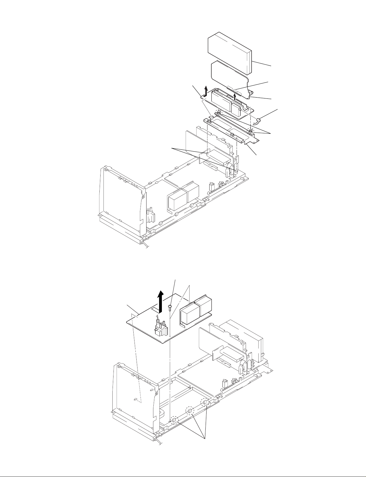
3-9. N AND A2 BOARDS REMOVAL
KP-51DS1U
KRM-892
3 N shield
1 Two bosses
8 A2 board
4 Claw
5 N board
6 Pin cable
7 Two claws
2 A2 bracket
3-10. E BOARD REMOVAL
3 E board
1 Two screws
(+BVTP 3 x 12)
– 29 –
2 Three claws
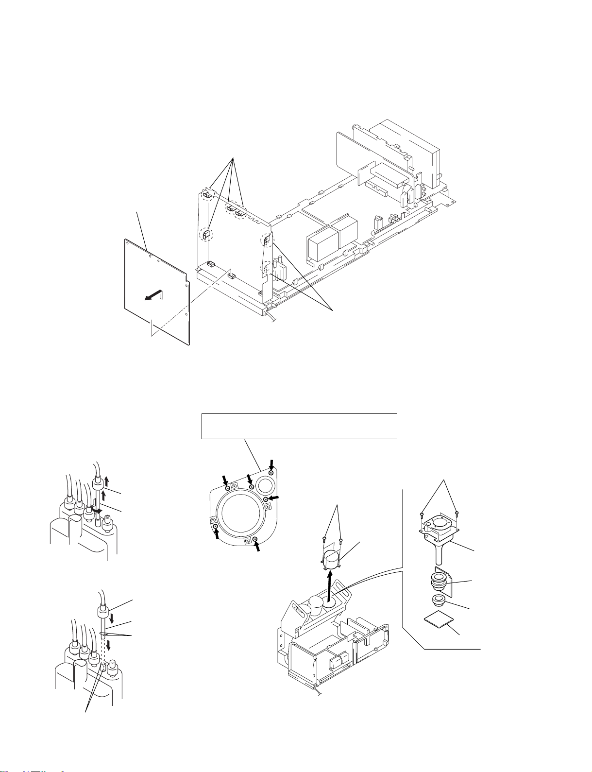
KP-51DS1U
KRM-892
3-11. G BOARD REMOVAL
2 G board
1 Four claws
1 Two claws
CABLE REMOVAL
AND INSTALLATION
(1) Removal
1 Rubber cap
2 HV cable
turn 90°
(2) Installation
2 Rubber cap
1 HV cable
Hook
3-13. PICTURE TUBE REMOVAL3-12. HIGH-VOLTAGE
Removing the arrow-marked screw is strictly inhibited.
If removed, it may cause liquid spill.
6 Four screws
(+BVTP 4 x 16)
1 Four screws
(+BVTP 4 x 16)
2 Lens
7 Picture
tube
5 Deflection
yoke
4 Neck
assembly
3 CR board
Gutter
– 30 –
 Loading...