

Sony klv46v400 schematic
REVISION HISTORY
EG1L(GA)
CHASSIS
MODEL
KLV-40V400A
KLV-46V400A
NO. SUFFIX DATE SUPP / CORR DESCRIPTION
1 -01 2008/6 _ _ 1st Issue
PA RT NO.: 9-872-997-02
2 -02 2008/7 Supp-1 New model addition KLV-40V400A/1 (Pg 34)

SERVICE MANUAL
EG1L(GA)
CHASSIS
MODEL COMMANDER DEST.
KLV-40V400A
KLV-46V400A
RM-GA011 E, EA, Egypt, India,
Iran, ME, Thailand,
Phillipines,
Saudi Arabia,
South Africa, Vietnam
RM-GA011 E, EA, India, Iran, ME,
Thailand, Phillipines,
Saudi Arabia,
South Africa, Vietnam
MODEL COMMANDER DEST.
KLV-40V400A
KLV-46V400A
RM-GA011
LCD COLOR TV

KLV-40,46V400A
RM-GA011
TABLE OF CONTENTS
Section Title Page
1. SAFETY NOTES
1-1. Caution Handling of LCD Panel ..................................... 3
1-2. Safety Check Out ............................................................. 3
1-3. Leakage Test .................................................................... 3
1-4. WARNING ! .................................................................... 3
1-5. LED Free Information ..................................................... 4
1-6. Caution ............................................................................. 5
2. SELF DIAGNOSTIC FUNCTION
2-1. Overview of Control Buttons .......................................... 6
2-2. LED Display Specification.............................................. 6
2-3. LED Display Control ....................................................... 6
2-4. LED Pattern ..................................................................... 6
2-5. Standby LED Error Displays .......................................... 7
3. DISASSEMBLY
3-1. Rear Cover Removal........................................................ 8
3-2. Stand Assy Removal ........................................................ 8
3-3. Switch Unit Removal ...................................................... 8
3-4. BG1 Board Removal ....................................................... 9
3-5. IP5 Board Removal ......................................................... 9
3-6. Vesa Frame Removal ....................................................... 9
3-7. H4, H3 and Speaker Removal ....................................... 10
3-8. LCD Panel and Assy Removal ...................................... 10
Section Title Page
6. DIAGRAMS
6-1. Block Diagram ............................................................... 20
6-2. Circuit Board Location .................................................. 20
6-3. Schematic Diagram ....................................................... 21
6-4. Printed Wiring Boards ................................................... 21
6-5. Semiconductor ............................................................... 21
7. EXPLODED VIEWS
7-1. KLV-40V400A ............................................................... 22
7-1-1. Rear Cabinet and Stand Assy ............................ 22
7-1-2. Frame and Cover ............................................... 23
7-1-3. Chassis-1 ............................................................ 24
7-1-4. H3E & H4 Board and Speaker ..........................25
7-1-5. Bezel Assy and LCD Panel ............................... 26
7-2. KLV-46V400A ............................................................... 27
7-2-1. Rear Cabinet and Stand Assy ............................ 27
7-2-2. Frame and Cover ............................................... 28
7-2-3. Chassis-1 ............................................................ 29
7-2-4. H3E & H4 Board and Speaker ..........................30
7-2-5. Bezel Assy and LCD Panel ............................... 31
8. ELECTRICAL PARTS LIST .............................................. 32
OPERATING INSTRUCTIONS
4. WIRE DRESSING
4-1. KLV-40V400A ......................................................... 11-13
4-2. KLV-46V400A ......................................................... 14-17
5. SERVICE ADJUSTMENTS
5-1. Accessing Diagnostic Menu .......................................... 18
5-2. Aging ............................................................................ 18
5-3. Resetting the User Menu- Factory Reset ...................... 18
5-4. White Balance Adjustment............................................ 19
5-5. Board and Panel Replacement ...................................... 19
– 2 –

SECTION 1
SAFETY NOTES
KLV-40,46V400A
RM-GA011
1-1. Caution Handling of LCD Panel
When installing the LCD Panel, make sure you are grounded
with a wrist band.
When installing the LCD Panel on the wall, the panel must be
secured using the 4 mounting holes on the rear cover.
1) Do not press the panel or frame edge to avoid the risk of
electric shock.
2) Do not scratch or press on the panel with any sharp
objects.
3) Do not leave the module in high temperature or in areas of
high humidity for an extended period of time.
4) Do not expose the LCD panel to direct sunlight.
5) Avoid contact with water. It may cause short circuit within
the module.
6) Disconnect the AC adapter when replacing the backlight
(CCFL) or inverter circuit. (High voltage occurs at the inverter
circuit at 650Vrms)
7) Always clean the LCD panel with a soft cloth material.
8) Use care when handling the wires or connectors of the
inverter circuit. Damaging the wires may cause a short circuit.
9) Protect the panel from ESD to avoid damaging the
electronic circuit (C-MOS).
1-2. Safety Check-Out
After correcting the original service problem, perform the
following safety checks before releasing the set to the
customer:-
1-3. Leakage Test
The AC leakage from any exposed metal part to earth
ground and from all exposed metal parts to any exposed
metal part having a return to chassis must not exceed 0.5mA
(500 microamperes). Leakage current can be measured by
any one of the three methods:-
1. A commercial leakage tester such as the SIMPSON 229
or RCA WT-540A. Follow the manufacturers instructions to
use those instructions.
2. A battery-operated AC milliampmeter. The DATA
PRECISION 245 digital multimeter is suitable for this job.
3. Measuring the voltage drop across a resistor by means
of a VOM or battery operated AC voltmeter. The 'limit' indication is 0.75V so analog meters must have an accurate low
voltage scale. The SIMPSON'S 250 and SANWA SH-63TRD
are examples of passive VOMs that are suitable. Nearly all
battery operated digital multimeters that have a 2 VAC range
are suitable. (see FIGURE 1)
To Exposed Metal
Parts on Set
0.15 µF
1.5 k
Ω
AC
Voltmeter
(0.75 V)
1) Check the area of your repair for unsoldered or poorly
soldered connections. Check the entire board surface for
solder splashes and bridges.
2) Check the interboard wiring to ensure that no wires are
"pinched" or contact high-wattage resistors.
3)Check all control knobs, shields, covers, ground straps and
mounting hardware have been replaced. Be absolutely certain
you have replaced all the insulators.
4) Look for unauthorized replacement parts, particularly
transistors that were installed during a previous repair. Point
them out to the customer and recommend their replacement.
5) Look for parts which, though functioning show obvious
signs of deterioration. Point them out to the customer and
recommend their replacement.
6) Check the line cords for cracks and abrasion.
Recommend the replacement of any such line cord to the
customer.
7) Check the antenna terminals, metal trim, "metallized"
knobs, screws and all other exposed metal parts for AC
leakage. Check leakage test as described next.
Earth Ground
Figure 1. AC voltmeter to check AC leakage
1-4. WARNING !
SAFETY-RELATED COMPONENT WARNING!
COMPONENTS IDENTIFIED BY SHADING AND MARK
!
ON THE EXPLODED VIEWS ARE CRITICAL FOR SAFE
OPERATION. REPLACE THESE COMPONENTS WITH
SONY PARTS WHOSE PART NUMBERS APPEAR AS
SHOWN IN THIS MANUAL OR IN SUPPLEMENTS
PUBLISHED BY SONY. CIRCUIT ADJUSTMENTS THAT ARE
CRITICAL FOR SAFE OPERATION ARE IDENTIFIED IN
THIS MANUAL. FOLLOW THESE PROCEDURES
WHENEVER CRITICAL COMPONENTS ARE REPLACED
OR IMPROPER OPERATION IS SUSPECTED.
– 3 –

KLV-40,46V400A
RM-GA011
1-5. LED Free Information
The circuit boards used in these models have been processed
using Lead Free Solder. The boards are identified by the LF
logo located close to the board designation.
Figure 2: LF logo
Figure 3: LF logo on circuit board
The servicing of these boards requires special precautions. It
is strongly recommended to use Lead Free Solder material in
order to guarantee optimal quality of new solder joints. Lead
Free Solder is available under the following part numbers:-
rebmuntraP retemaiD skrameR
7
91-500-046-mm
02-500-046-7m4.0Kg05.0
12-500-046-7m5.0Kg05.0
22-500-046-7m6.0Kg52.0
32-500-046-7m8.0Kg00.1
42-500-046-7m0.1Kg00.1
52-500-046-7m2.1Kg00.1
62-500-046-7m6.1Kg00.1
3.0Kg52.0
m
m
m
m
m
m
m
Due to high melting point of Lead Free Solder, the soldering
iron tip temperature needs to be set to 370 degrees
centigrade. This requires soldering equipment capable of
accurate temperature control coupled with a good heat
recovery characteristics.
For more information on the use of Lead Free Solder,
please refer to http://www.sony-training.com
– 4 –
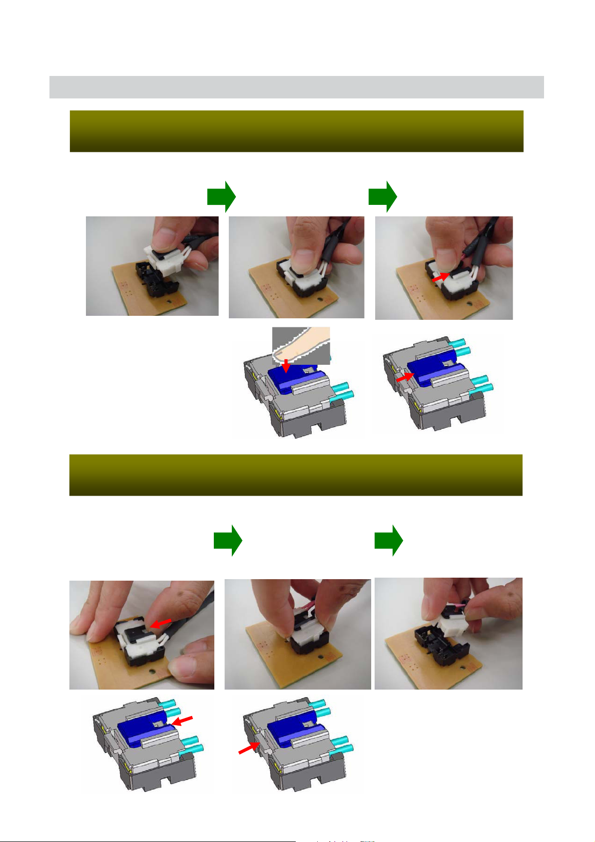
1-6. Cauton
Attachment of HIROSE MDF 61 connector
1. Insertion
(1) Hold the center
of a connector
CAUTION
(2) Press the center of
the connector to insert
it
KLV-40,46V400A
RM-GA011
(3) Slide the
slider to lock the
connector
Detachment of HIROSE MDF61 connector
2. Detachment
(1) Slide the slider to
release the slider lock
Lock
(2) Press the center
lock tab to release
the lock and pull the
connector up
Unlock
– 5 –

KLV-40,46V400A
RM-GA011
SECTION 2
SELF DIAGNOSTIC FUNCTION
2-1. Overview of Control Buttons
MENU TV/VIDEO VOLUME PROG POWER
2-4. LED Pattern
When safety shutdown occurs, Standby LED display reports the
cause by using the lightning patterns as indicated below.
0.3 sec
0.3 sec
2.0 sec 2.0 sec
Example:
The figure above shows LED display when
SHUTDOWN is caused by DC_ALERT 2. It repeats
flashing for a specified number of times in 0.3sec/
cycle and has a 2 seconds interval of lighting off.
Please note that a 2 seconds interval of lighting off
is fixed regardless of abnormal state types.
LIGHT
SENSOR
PICTURE
OFF/TIMER
INDICATOR
STANDBY
INDICATOR
POWER
REMOTE
SENSOR
2-2. LED Display Specification
LED Typ e Description
POWER Green: LED
Remark
Green lights at power ON.
STANDBY Red: One LED Red lights during standby.
Green lights during Picture
OFF and amber lights
Timer
Green/Amber
: Two LEDs
during Timer activation.
2-3. LED Display Control
Status
Power LED
Display
Standby LED
POWER ON Green lights OFF
STANDBY
OFF Red lights
Failure
Remark
Microcomputer is
in a normal state.
Microcomputer is
in a sleep state.
Classify the
trouble causes by
the no. of red.
– 6 –
2-5. Standby LED Error Display
Perform below countermeasures according to Standby LED blinking times.
Blinking times Error Countermeasure
2 DC_DET (12V Main Voltage) Replace either/both z BG1 board
z IP5 board
3 DC_ALERT 1 Replace BG1 board.
4 DC_ALERT 2 Replace BG1 board.
5 DC_ALERT 3 Replace BG1 board.
6BACKLIGHT/ Replace BG1 board.
INVERTER ERROR
KLV-40,46V400A
RM-GA011
7 INTERNAL TEMP Replace IP5 board
ERROR
8AUDIO ERROR Replace either/both z BG1 board
z IP5 board
z Speaker
9 Not used for GA —
10 Not used for GA —
11 NVM ERROR Replace either/both z BG1 board
z IP5 board
12 IIC ERROR Replace BG1 board.
13 BALANCER ERROR Replace BG1 board.
14 HDMI ERROR —
Note: Each of the above blinking repeats every 2 seconds.
– 7 –

KLV-40,46V400A
RM-GA011
3-1. Rear Cover Removal
SECTION 3
DISASSEMBLY
(KLV-46V400A)(KLV-40V400A)
3 Two screws
(+PSW M3 X 5)
1 Nineteen screws
(BVTP2 4 X 16)
2 Two screws
(+BVTP 3 X 12)
4 Two screws
(PSW 5 X 8)
5 Four screws
(+PSW 5 X 16)
6 Lift to remove
Rear Cover
1 Twenty one screws
(BVTP2 4 X 16)
2 Two screws
(+BVTP 3 X 12)
3 Two screws
(+PSW M3 X 5)
3-2. Stand Assy Removal
(KLV-40V400A) (KLV-46V400A)
1 Three screws
(+PSW 5 X 16)
2 Stand assy
4 Two screws
(PSW 5 X 8)
5 Four screws
(+PSW 5 X 16)
6 Lift to remove
Rear Cover
1 Four screws
(+PSW 5 X 16)
2 Stand assy
3 Two screws
(BVTP2 4 X 16)
4 Under Bar (M) Assy
3-3. Switch Unit Removal
(KLV-40V400A) (KLV-46V400A)
3 Switch unit
2 Lift tabs to
1
remove board
3 Switch unit
3 Two screws
(BVTP2 4 X 16)
4 Under Bar Assy
Lift tabs to
2
remove board
1
– 8 –
3-4. BG1 Board Removal
KLV-40,46V400A
RM-GA011
(KLV-46V400A)(KLV-40V400A)
2 One connector
1 Six screws
(+PSW 3SG)
3 One connector
4 IP5 board
1 Six screws
(+PSW 3SG)
2 One connector
3-5. IP5 Board Removal
(KLV-40V400A) (KLV-46V400A)
1 One screw
(+BVST 3 X 5)
3 Eight connectors
5 Side Jack Bracket Assy
2 Nine screws
(+BVST 3 X 8)
4 BG1 board
6 Two screws
(+BVST 3 X 8)
7 Main Bracket
1 One screw
(+BVST 3 X 5)
3 Eight connectors
3 One connector
4 IP5 board
5 Side Jack Bracket Assy
2 Nine screws
(+BVST 3 X 8)
4 BG1 board
6 Two screws
(+BVST 3 X 8)
7 Main Bracket
3-6. Vesa Frame Removal
(KLV-40V400A) (KLV-46V400A)
1 One screw
(+PSW M4 X 8)
2 Under Cover (M)
8 Two screws
(+PSW M4 X 8)
4 Two screws
(PSW 5 X 8)
qa Two screws
(+PSW M4 X 8)
qs Frame Spine (R)
qd One screw
(+PSW M4 X 8)
qf Four screws
(BVTP2 4 X 16)
qg Frame Bottom
3 Two screws
(+PSW M5 X 8)
4 Two screws
(+PSW M5 X 8)
5 Two screws
(PSW 5 X 8)
q; Two screws
(+PSW M5 X 8)
qa One screw
(+PSW M5 X 8)
qs Frame, spine (L)
6 Two screws
(+PSW M5 X 8)
qf Two screws
(+PSW M5 X 8)
qg One screw
(+PSW M5 X 8)
qk One screw
(+PSW M5 X 8)
5 Two screws
(PSW 5 X 8)
7 One screws
(BVTP2 4 X 16)
9 Frame, spine (L)
6 Two screws
(+PSW M4 X 8)
q; One screw
(BVTP2 4 X 16)
3 Two screws
(PSW 5 X 8)
– 9 –
1 One screw
(+PSW M5 X 8)
2 Under Cover
8 Three screws
(+PSW M5 X 8)
7 Two screws
(PSW 5 X 8)
qd Three screws
(+PSW M5 X 8)
qh Frame Spine (R)
qj One screw
(+PSW M5 X 8)
ql
One screw
(+PSW M5 X 8)
w;
Four screws
(BVTP2 4 X 16)
wa Frame Bottom

KLV-40,46V400A
RM-GA011
3-7. H4, H3 and Speaker Removal
(KLV-46V400A)(KLV-40V400A)
1 Four screws
(+BVTP 3 X 12)
4 One screw
(+BVTP 3 X 12)
5 H3E board
6 H4 board
7 One screw
(+BVTP 3 X 12)
8 Guide Light
qa Bezel assy
3 Loudspeaker (5.5 X 12cm)
2 Four screws
(+BVTP 3 X 12)
9 One screw
(+BVTP 3 X 12)
q; Clear panel
1 Four screws
(+BVTP 4 X 12)
4 One screw
(+BVTP 3 X 12)
5 H3E board
6 H4 board
7 One screw
(+BVTP 3 X 12)
8 Guide Light
qa Bezel assy
3-8. LCD Panel and Bezel Assy Removal
(KLV-40V400A) (KLV-46V400A)
2 Harness
with connector
1 Two screws
(BVTP2 4 X 16)
3 Loudspeaker (5.5 X 12cm)
2 Four screws
(+BVTP 3 X 12)
9 One screw
(+BVTP 3 X 12)
q; Clear panel
2 Harness
with connector
1 Two screws
(BVTP2 4 X 16)
4 Bezel assy
3 LCD panel
3 LCD panel
4 Bezel assy
– 10 –
KLV-40,46V400A
SECTION 4
WIRE DRESSING
Legend
HookSlide Clamp
CAUTION :
1. Do not overpull the wires during dressing
--> avoid disconnection of wires.
2. Make sure wires are kept away from
sharp edges, heatsinks & other
high-temperature parts.
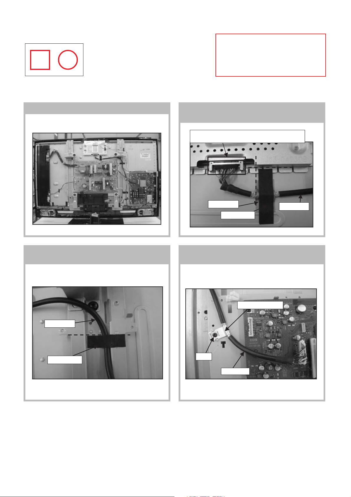
4-1.(KLV-40V400A)
4-1-1. Wire dressing overview 4-1-2. Dress LVDS cable with Sheet Core C &
Shield Tape as shown
Make sure LVDS connector fully inserted with correct
direction as shown.
Datum
Datum
RM-GA011
4-1-3. Dress LVDS cable with Sheet Core C on
spine frame as shown
LVDS cable
Datum
Sheet Core C
Shield Tape
Sheet Core C
LVDS cable
4-1-4. Screw LVDS cable's clamp on main bracket
as shown
LVDS cable's clamp
Screw
LVDS cable
– 11 –

KLV-40,46V400A
RM-GA011
4-1-5. Dress Connector Assy 14P+20P & Speaker
Wire with sheet core C(2X) as shown
Sheet Core C
Datum
Datum
Connector assy
14P+20P
Speaker Wire
Follow White
UL tape
as guide to
apply tape
4-1-6. Dress Connector Assy 14P+20P & Speaker wire with sheet core C(3X) as shown.
Datum
Datum
Sheet Core C
Connector assy
14P+20P
Datum
Connector assy
14P+20P
Sheet Core C
Dress wire along panel edge
4-1-7. 1) Connector Assy 40P+20P
2) Dress Connector Assy 14P+20P with
slide clamp(2X) as shown.
Connector assy 14P+20P
Connector assy 13P
Speaker Wire
Dress wire along panel edge
4-1-8. 1) Dress Connector Assy 14P+20P on top
of Connector Assy 13P as shown.
2) Dress Connector Assy 14P+20P with
LCD tape as shown.
Connector assy 14P+20P
Datum
LCD Tape
– 12 –

4-1-9. 1) Ground Wire and Speaker Wire
2) Screw Gound wire and dress underneath speaker wire as shown.
Speaker Wire
4-6-2. Dress speaker wire with LCD tape as
shown
Ground Wire
Ground Wire
KLV-40,46V400A
RM-GA011
Ground Wire
~90
~45
Speaker Wire
4-1-10. 1) Inverter Wire and Connector Assy 7P
2) Dress Inverter wire with clamp(2X) as
shown.
Clamp
Inverter wire
Lock the
connector
after install
Clamp
Lock the
connector
after install
LCD Tape
Datum
4-1-11. 1) Dress Connector assy 7P with LCD
tape as shown.
Connector assy 7P
LCD Tape
Datum
4-1-12. 1)
2)
AC Inlet Wire and Connector Assy 14P+20P
Dress AC Inlet wire with Sheet Core
C(2X) as shown.
Sheet Core C
Datum
AC Inlet wire
– 13 –
4-1-13. 1) Dress Connector assy 14P+20P with
LCD tape(2X) as shown.
Datum
Connector assy 14P+20P
Datum
LCD tape

KLV-40,46V400A
RM-GA011
4-2.(KLV-46V400A)
4-2-1. OVERALL VIEW
4-2-2. Dress LVDS
1) Dress LVDS cable with Sheet Core C(2X) & Shield Tape as shown in figure A.
2) Dress LVDS cable with Sheet Core C on spine frame as shown in figure B.
3) Screw LVDS cable's clamp on main bracket as shown in figure C.
Make sure LVDS connector fully inserted
with correct direction as shown.
Datum
LVDS cable
Shield Tape
Sheet Core C
Figure A
Datum
Datum
Sheet Core C
LVDS cable
Figure B
LVDS cable's clamp
– 14 –
Screw
LVDS cable
Figure C

4-2-3. Dress Connector Assy 4-2-4. Dress Connector Assy
Dress Connector Assy 14P+20P
& Speaker Wire with sheet core C(2X) as shown in figure D.
Dress Connector Assy 14P+20P & Speaker wire with sheet
core C(4X) as shown in figure E & F.
KLV-40,46V400A
RM-GA011
Datum
Sheet Core C
Datum
Follow White UL tape
as guide to apply tape
Connector assy 14P+20P
Speaker Wire
Figure D
Speaker
Wire
4-2-5. Dress Connector Assy
1) Dress Connector Assy 14P+20P with slide clamp(2X) as shown in figure G.
2) Dress Connector Assy 14P+20P on top of Connector Assy 13P as shown in figure G.
3) Dress Connector Assy 14P+20P with LCD tape as shown in figure H.
Datum
Sheet Core C
Connector assy 14P+20P
Dress wire along panel edge
Sheet Core C
Datum
Connector assy 14P+20P
Dress wire along panel edge
Figure E
Datum
Speaker Wire
Datum
Figure F
Connector assy 14P+20P
Connector assy 13P
Figure G
Connector assy 14P+20P
Datum
LCD Tape
Figure H
– 15 –

KLV-40,46V400A
K
RM-GA011
4-2-6. Speaker Wire
1) Screw Ground wire and dress underneath speaker wire as shown in figure I,J&K.
2) Dress speaker wire with LCD tape as shown in figure K.
Speaker Wire
Ground Wire
Ground Wire
Figure I
Figure J
Ground Wire
~45
Speaker Wire
4-2-7. Connector Assy at Speaker Bracket
Dress Connector assy 14P+20P at speaker bracket's hook as shown in figure L&M.
Connector assy 14P+20P
Figure L Figure M
LCD Tape
Datum
Figure
Connector assy 14P+20P
Dress H3E connector assy with speaker bracket's hook
at the area without UL tape
– 16 –

4-2-8. Dress Inverter Wire and Dress Connector Assy
1) Dress inverter wire with Sheet Core E as shown in figure N.
2) Dress Connector assy 7P with LCD tape as shown in figure O
Caution:
Keep Inverter wire away from
spine frame's sharp edge area
KLV-40,46V400A
RM-GA011
Inverter wire
Lock the connector
after install
Lock the connector
after install
Datum
Sheet Core E
Datum
Figure N Figure O
4-2-9. Dress AC Inlet Wire and Dress Connector Assy
1) Dress AC inlet wire with Sheet Core C(2X) as shown in figure P.
2) Dress Connector assy 14P+20P with LCD tape(2X) as shown in figure Q.
LCD Tape
Connector assy 7P
Sheet Core C
AC Inlet wire
Datum
Figure P
Datum
LCD tape
Connector assy 14P+20P
Datum
Figure Q
– 17 –

KLV-40,46V400A
ERROR
DC_DET
DC_ALERT1
DC_ALERT2
DC_ALERT3
BACKLIGHT
INTERNAL TEMP ERROR
AUDIO ERROR
NVM ERROR
IIC ERROR
BALANCER ERROR
HDMI ERROR
0
0
0
0
0
0
0
0
0
0
0
RESET
0
RM-GA011
SECTION 5
SERVICE ADJUSTMENTS
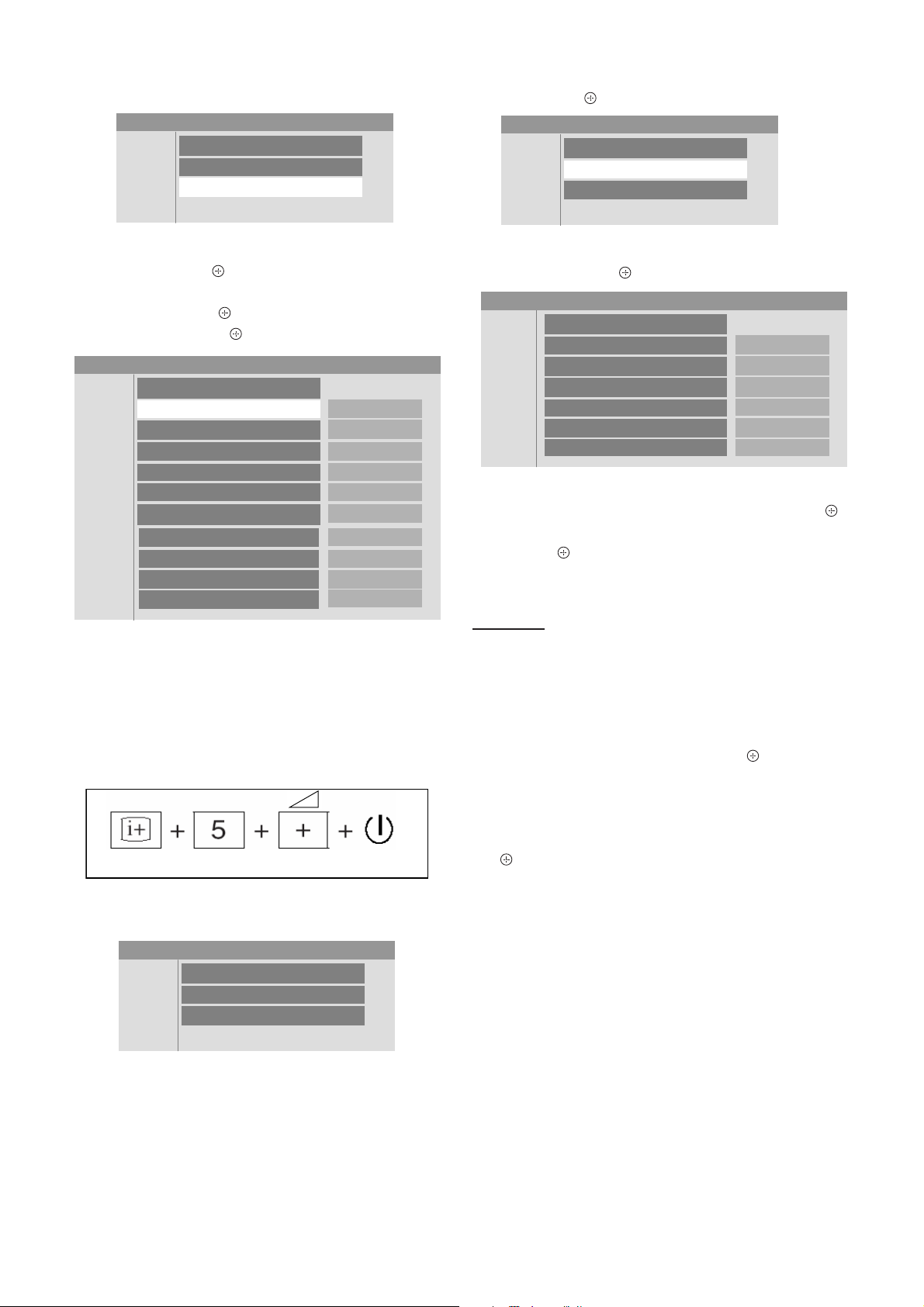
5-1. Accessing Diagnostic Menu
1. While TV set on standby, press the following sequence on
the remote commander (RM-GA011).
On screen
display
Channel 5
Volume (-)
POWER
2. The following menu will appear on the screen:
Figure 1
3. To reset, select ‘RESET’ using remote commander and
press
to execute RESET.
4. To quit the diagnostic menu, turn off and on the TV set.
5-2. Aging
1. While TV set on standby, press the following sequence on
the remote commander (RM-GA011).
3. Press V/v to select ‘Service’.
Service Menu
Status
W/B
Service
Figure 4
4. Press B/b or
to view ‘Service’ category items.
Press V/v to select ‘PATTERN’. Then press B/b then V/v
to select ‘WHITE PATTERN’ and .
Service Menu
Service
TEST RESET
PATTERN
PRODUCTION
APC
OVER MODULATION
OPTIONS
AUTOSET FACTORY
SERIAL NUMBER EDIT
ETI1 CLEAR
No Signal Mute
Cancel
WHITE PATTERN
11111111
Normal
Off
OPT 1
DEFAULT
Cancel
Off
Figure 5
5. The aging Condition is as the following:
a) Supply voltage : Rating
b) Time : 20 minutes or over
c) Ambient Temp : 22~28 degrees
5-3. Resetting the User Menu - Factory Reset
On screen
display
Channel 5 Volume (+)
Figure 2
2. The following menu will appear on the screen.
Service Menu
Status
W/B
Service
Figure 3
POWER
Note: THE TEST RESET option resets all the customer
adjustable data back to factory defaults.
1. While TV set on standby, press the following sequence on
the remote commander (RM-GA011).
On screen
display
Channel 5
Volume (-)
POWER
Figure 6
2. The following menu will appear on the screen:
Service Menu
Status
W/B
Service
Figure 7
– 18 –
KLV-40,46V400A
RM-GA011
3. Press V/v to select ‘Service’.
Service Menu
Status
W/B
Service
Figure 8
4. Then press B/b or
to view ‘Service’ category items.
Next select ‘TEST RESET’ by pressing V/v .
5. Finally press B/b or then V/v to select ‘OK’ and confirm
selection by pressing .
Service Menu
Service
TEST RESET
PATTERN
PRODUCTION
APC
OVER MODULATION
OPTIONS
AUTOSET FACTORY
SERIAL NUMBER EDIT
ETI1 CLEAR
No Signal Mute
Cancel
Off
11111111
Normal
Off
OPT1
DEFAULT
Cancel
Off
Figure 9
5-4. White Balance Adjustment
Note: The white balance need to be adjusted when BG1 board
and Panel is replaced.
1. While TV set on standby, press the following sequence on
the remote commander (RM-GA011).
3. Press B/b or
to view ‘W/B’.
Service Menu
Status
W/B
Service
Figure 12
4. Then press B/b or to view ‘W/B’ category items.
Service Menu
W/B
INITIALIZE
LEVEL
R_DRIVE
G_DRIVE
B_DRIVE 0
COLOR_SAVE
INIT START
0
0
0
Cancel
Figure 13
5. Press V/v to select ‘INITIALIZE’. Then press B/b or
then V/v to select ‘INIT START’ and execute selection by
pressing .
6. W/B need to be adjusted for all LEVEL (0~4).
For Level 0
7. Select 'LEVEL' using V/v and choose ‘0’.Then do
adjustment for R_Drive, G_Drive and B_Drive. To increase/
decrease data value, press V/v .
8. Once adjustment has completed for R_Drive, G_Drive and
B_Drive, press V/v to select ‘COLOR SAVE’. Next press
B/b then V/v to choose ‘OK’ and press
.
9. Repeat step 7 and 8 for level 1~4.
On screen
display
Channel 5
Volume (-)
POWER
Figure 10
2. The following menu will appear on the screen:
Service Menu
Status
W/B
Service
Figure 11
10. Once W/B adjustment has been completed for all levels
(0~4), select ‘INITIALIZE’, choose ‘INT END’ and press
.
5-5. Board & Panel Replacement
When replacing the BG1 board and Panel, make sure to readjust
the W/B.
– 19 –

KLV-40,46V400A
RM-GA011
6-1. BLOCK DIAGRAM
SECTION 6
DIAGRAMS
Due to complexity of the board, performing
component level field repairs are not recommended.
Complete board replacement is required if service is
necessary.
6-2. CIRCUIT BOARD LOCATION
BG1 Board
KLV-40V400A KLV-46V400A
Switch Unit
IP5 Board
H4 Board
H3E Board
Switch Unit
IP5 Board
BG1 Board
H4 Board
H3E Board
– 20 –

6-3. SCHEMATIC DIAGRAM 6-4. PRINTED WIRING BOARDS
Board Function Note
KLV-40,46V400A
RM-GA011
BG1 I/O/Audio/VCTP/DDR/HDMI/ Due to complexity of the board, performing
IP5 Power Supply necessary.
H3E LED/Optical Sensor printed wiring boards are not included.
H4 SIRCS Exploded View or Electrical Parts List
6-5. SEMICONDUCTOR
DC-DC Converter/Tuner/Sub component level field repairs are not
Croma/STBY Micro recommended. Complete board
replacement is required if service is
Therefore schematic diagrams and
For part number information, refer to
section in this manual.
Due to complexity of the board, performing
component level field repairs are not recommended.
Complete board replacement is required if service is
necessary.
– 21 –

KLV-40,46V400A
RM-GA011
SECTION 7
EXPLODED VIEWS
• Components not identified by a part
number or description are not stocked
because they are not required for routine
service.
NOTE: The components identified by shading and ! mark are
critical for safety. Replace only with part number specified.
Note: The components identified by mark contain
confidential information. Strictly follow the instructions
whenever the components are repaired and /or replaced.
• The component parts of an assembly
are indicated by the reference numbers
in the far right column of the part list and
within the dotted lines of the diagram.
7-1. (KLV-40V400A)
7-1-1. REAR CABINET AND STAND ASSY
f
l
k
f
a
f
• Item marked with an asterisk (*) are not
stocked since they are seldom required
for routine service. Some delay should
be anticipated when ordering these
components.
a 2-580-591-01 SCREW, +PSW M3X5
b 2-580-600-01 SCREW, +PSW M4X8
c 2-580-606-01 SCREW, +PSW M5X8
d 2-580-626-01 SCREW, SP 4-4O UNC
e 2-580-629-01 SCREW, +BVST 3X8
f 2-580-640-01 SCREW, +BVTP2 4X16
g 2-580-644-01 SCREW, +KTP2 3X8
h 2-674-965-31 SCREW, +PSW 3SG
i 3-873-012-01 SCREW, +PWH M5X16
j 3-873-013-01 SCREW, +PWH M5X10
k 7-685-648-79 SCREW, +BVTP 3X12 TYPE2 IT-3
l 2-580-608-01 SCREW +PSW M5X16
m 2-596-649-01 +KTT 3X10 (5 TYPE)
n 2-580-607-01 SCREW, +PSW M5X12
1
f
j
3
12
j
g
2
REF. NO. PART NO. DESCRIPTION REMARK
1*3-106-086-01 COVER, ECS
2 X-2189-410-2 STAND(ML)ASSY
3 4-103-642-21 EMBLEM, SONY NO.8
i
– 22 –
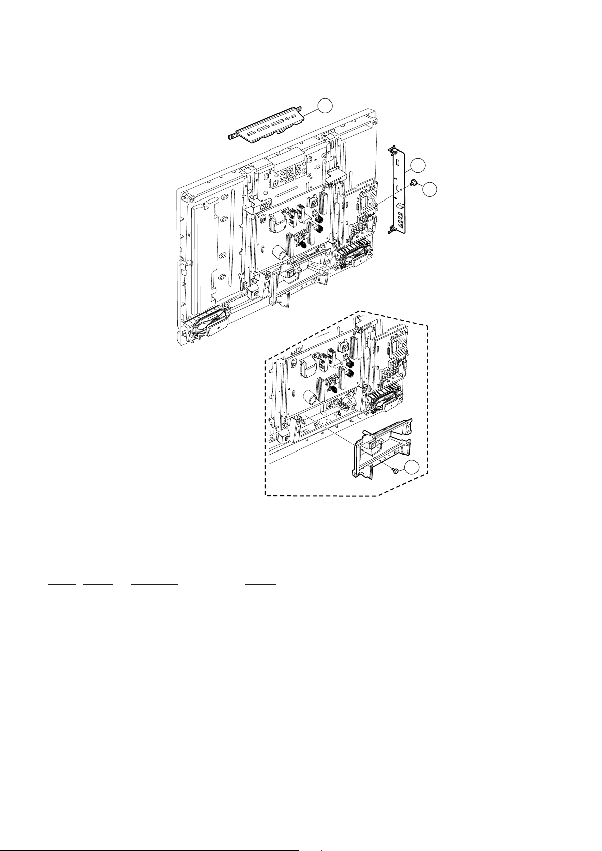
7-1-2. FRAME AND COVER
KLV-40,46V400A
RM-GA011
51
52
a
REF. NO. PART NO. DESCRIPTION REMARK
51 1-480-709-11 SWITCH UNIT
52 X-2318-678-1 BRACKET SIDE JACK ASSY (PF1)
k
– 23 –

KLV-40,46V400A
RM-GA011
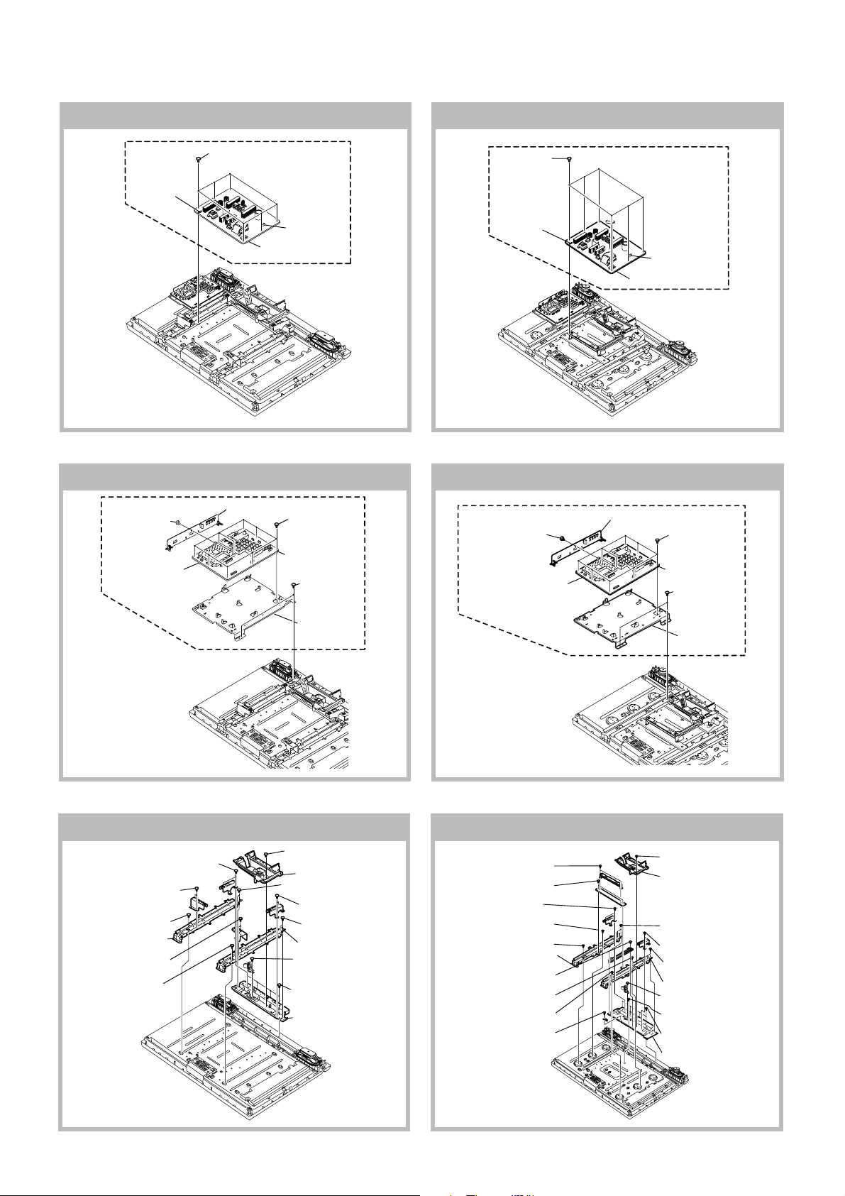
7-1-3. CHASSIS-1
102
103
c
104
m
n n
101
c
e
c
a
n
n
e
c
e
n
n
REF. NO. PART NO. DESCRIPTION REMARK
101 A-1511-380-D IP5-40S COMPL (STT)
(ME, Phillipines, South Africa, Thailand)
A-1511-388-D IP5-40S COMPL (SOEM)
(except ME, Phillipines, South Africa, Thailand)
102 A-1543-889-A BG1 MOUNT (SERVICE)
103 1-821-909-11 AC INLET
104 3-293-964-01 BRACKET, AC INLET
– 24 –

7-1-4. H3E & H4 BOARDS AND SPEAKER
KLV-40,46V400A
RM-GA011
154
151
k
k
152
154
k
153
REF. NO. PART NO. DESCRIPTION REMARK
151 * A-1530-492-A H4 MOUNT
152 * A-535-202-A H3E MOUNT
153 1-826-889-12 LOUDSPEAKER (5.8X12.6CM)
154 1-826-889-22 LOUDSPEAKER (5.8X12.6CM)
155 * 3-290-361-02 GUIDE, LIGHT
k
– 25 –
 Loading...