

Page 1

Hard Disk
Recording Unit
2-898-341-11(1)
Operating Instructions
Owner’s record
The model number and the serial number are located at the name plate on the left of the
unit. Record the serial number in the space provided below. Refer to these numbers
whenever you call upon your Sony dealer regarding this product.
Model No. HVR- Serial No. ______________________
HVR-DR60
2006 Sony Corporation
Page 2
WARNING
To reduce fire or shock hazard, do not
expose the unit to rain or moisture.
If you have any questions about this product, you may
call: Sony’s Business Information Center (BIC) at 1-800686-SONY (7669)
Declaration of Conformity
CAUTION
Replace the battery with the specified type
only. Otherwise, fire or injury may result.
PRECAUTION
• Even if this unit is turned off, AC power (house current) is
still supplied to it while connected to the wall outlet via the
AC Adaptor.
For the customers in the U.S.A.
This symbol is intended to alert the user to the
presence of uninsulated “dangerous voltage”
within the product’s enclosure that may be of
sufficient magnitude to constitute a risk of
electric shock to persons.
This symbol is intended to alert the user to the
presence of important operating and
maintenance (servicing) instructions in the
literature accompanying the appliance.
Trade Name: SONY
Model: HVR-DR60
Responsible Party: Sony Electronics Inc.
Address: 16530 Via Esprillo, San Diego,
CA 92127 U.S.A.
Telephone Number: 858-942-2230
This device complies with Part 15 of the FCC Rules.
Operation is subject to the following two conditions:
(1) This device may not cause harmful interference, and (2)
this device must accept any interference received,
including interference that may cause undesired operation.
CAUTION
You are cautioned that any changes or modifications not
expressly approved in this manual could void your authority
to operate this equipment.
NOTE:
This equipment has been tested and found to comply with
the limits for Class B digital device, pursuant to Part 15 of the
FCC Rules.
These limits are designed to provide reasonable protection
against harmful interference in a residential installation.
This equipment generates, uses, and can radiate radio
frequency energy and, if not installed and used in accordance
with the instructions, may cause harmful interference to radio
communications.
However, there is no guarantee that interference will not
occur in a particular installation. If this equipment does cause
harmful interference to radio or television reception, which
can be determined by turning the equipment off and on, the
user is encouraged to try to correct the interference by one or
more of the following measures:
– Reorient or relocate the receiving antenna.
– Increase the separation between the equipment and
receiver.
– Connect the equipment into an outlet on a circuit different
from that to which the receiver is connected.
– Consult the dealer or an experienced radio/TV technician
for help.
The supplied interface cable must be used with the
equipment in order to comply with the limits for a digital
device pursuant to Subpart B of Part 15 of FCC Rules.
2
Page 3

For the customers in Europe
This product with the CE marking complies with both the
EMC Directive (89/336/EEC) issued by the Commission of
the European Community.
Compliance with these directives implies conformity to the
following European standards:
• EN55103-1 :Electromagnetic Interference (Emission)
• EN55103-2 :Electromagnetic Susceptibility (Immunity)
This product is intended for use in the following
Electromagnetic Environment(s):
E1 (residential), E2 (commercial and light industrial), E3
(urban outdoors) and E4 (controlled EMC environment ex.
TV studio).
ATTENTION
The electromagnetic fields at the specific frequencies may
influence the picture and sound of this unit.
This product has been tested and found to comply with EMC
regulations when the cable connected to the i.LINK jack does
not exceed 1 m in length. Please connect a cable that does not
exceed 1 m to the i.LINK jack.
Disposal of Waste Electrical and Electronic
Equipment for business use (Applicable in
the European Union and other European
countries with separate collection systems)
This symbol on the product or on its packaging
indicates that this product shall not be treated as
household waste. Instead it shall be handed over
to the applicable take-back scheme for the
recycling of electrical and electronic equipment.
By ensuring this product is disposed of correctly,
you will help prevent potential negative
consequences for the environment and human health, which
could otherwise be caused by inappropriate waste handling
of this product. The recycling of materials will help to
conserve natural resources. For more detailed information
about recycling of this product, please contact your local
Sony office or visit Sony Europe’s web site for business
customers:
http://www.sonybiz.net/environment
Caution
Television programs, films, video tapes and other materials
may be copyrighted. Unauthorized recording of such
material may be contrary to the provisions of the copyright
laws. Also, use of this recorder with cable television
transmission may require authorization from the cable
television transmission and/or program owner.
3
Page 4

Table of contents
Overview ........................................................ 5
Features ................................................................................ 5
Names of parts............................................... 6
Hard Disk Recording Unit................................................. 6
LCD screen display............................................................. 7
Getting prepared ........................................... 8
Preparing the power supply ............................................. 8
Using in VIDEO mode .................................. 10
Connecting this unit to a camcorder .............................. 10
Menu settings .................................................................... 10
Menu organization ...................................... 11
Recording images from the camcorder to this
unit ............................................................... 13
Recording images
(POWER switch at the VIDEO side) .............................. 13
On trademarks
• “InfoLITHIUM” is a trademark of Sony Corporation.
• i.LINK and
• HDV and the HDV logo are trademarks of Sony
Corporation and Victor Company of Japan, Ltd.
• Microsoft, Windows, and Windows Media are either
registered trademarks or trademarks of Microsoft
Corporation in the United States and/or other countries.
• Macintosh is a trademark of Apple Computer, Inc. in the
U.S. and other countries.
• Pentium is a trademark or registered trademark of Intel
Corporation.
All other product names mentioned herein may be the
trademarks or registered trademarks of their respective
companies. Furthermore, ™ and “®” are not mentioned in
each case in this manual.
Notes on the License
ANY USE OF THIS PRODUCT OTHER THAN CONSUMER
PERSONAL USE IN ANY MANNER THAT COMPLIES
WITH THE MPEG-2 STANDARD FOR ENCODING VIDEO
INFORMATION FOR PACKAGED MEDIA IS EXPRESSLY
PROHIBITED WITHOUT A LICENSE UNDER APPLICABLE
PATENTS IN THE MPEG-2 PATENT PORTFOLIO, WHICH
LICENSE IS AVAILABLE FROM MPEG LA, L.L.C., 250
STEELE STREET, SUITE 300, DENVER, COLORADO 80206.
are trademarks of Sony Corporation.
Playback the image from the camcorder ... 15
Playback (POWER switch to VIDEO) ............................ 15
Useful functions in combination with HVR- V1U/V1N/
V1E/V1P ............................................................................ 16
Using in COMPUTER mode.......................... 19
Folder saving format ................................... 20
Folder organization .......................................................... 20
HDD organization ............................................................ 21
Trouble shooting.......................................... 22
Warning indicators ...................................... 24
Notes on using the hard disk drive ............ 25
About i.LINK ................................................. 26
Specifications ............................................... 27
Precautions................................................... 28
Getting the best performance from the
battery pack ................................................. 29
4
Page 5

Overview
Features
• Long recording time, small and light body
The 1.8-inch internal HDD provides a large 60 GB capacity.
Although the HVR-DR60 only weighs about 230 g, it
enables about 4.5 hours of recording of an HDV/DVCAM/
DV stream.
Using the supplied shoe adaptor lets you mount the drive
onto an HVR-V1U/V1N/V1E/V1P, where it will not affect
the mobility of the camcorder. Using high capacity
InfoLITHIUM L series battery packs, the HVR-DR60
operating time for continuous recording is approximately
18 hours.
• Two types of operating mode
The HVR-DR60 offers two types of operating mode, VIDEO
mode and COMPUTER mode.
VIDEO mode
VIDEO mode is for recording an HDV/DVCAM/DV
stream via the i.LINK jack on a camcorder. When
connecting to a camcorder that has an external REC control
function, you can control this unit from the camcorder
using “SYNCHRO mode,” in which video and audio
material is recorded simultaneously to the HVR-DR60 and
tape. When connecting to a camcorder that does not have
an external REC control function, you can select “FOLLOW
mode,” in which HVR-DR60 regularly checks the status of
the camcorder and follows the camcorder operation.
COMPUTER mode
In COMPUTER mode, the HVR-DR60 is recognized as a
standard external drive when connected to a computer via
an i.LINK cable. The HVR-DR60 enables efficient operation
with a transfer speed three times faster than real time.
• HDD smart protection
The “HDD smart protection” function has three
components: a shock absorber, which uses shock absorbing
material to envelope the HDD and protect it from physical
shock; a 3G sensor, which automatically retracts the
recording head when it detects gravitational acceleration
exceeding a certain level; and a buffer memory, which
continues recording to the memory for up to 14 seconds
when the recording head is retracted. This function protects
recorded video and audio data from the impact of a drop of
up to about 100 cm.
• Useful function with the HVR-V1U/V1N/V1E/V1P
The combination of this unit and the HVR-V1U/V1N/
V1E/V1P offers more useful functions.
Tapeless external REC control
When used with this unit, the HVR-V1U/V1N/V1E/V1P
can output the record command without a tape, so the unit
is synchronized to the REC/STOP operation of the HVRV1U/V1N/V1E/V1P enabling video to be recorded on the
unit only.
Displaying the operational status of this unit on the
HVR-V1U/V1N/V1E/V1P LCD screen
You can check the current condition of this unit and its
operational status (remaining recording time, battery level,
recording format etc.) on the LCD screen of the HVR-V1U/
V1N/V1E/V1P. Not having to check the unit itself means
you can concentrate more on what you are shooting.
Supported models
The HVR-DR60 can be used connected to the camcorder/
VTR.
For details of supported models, refer to the supplied “Guide
to supported models and their functions.”
5
Page 6
Names of parts
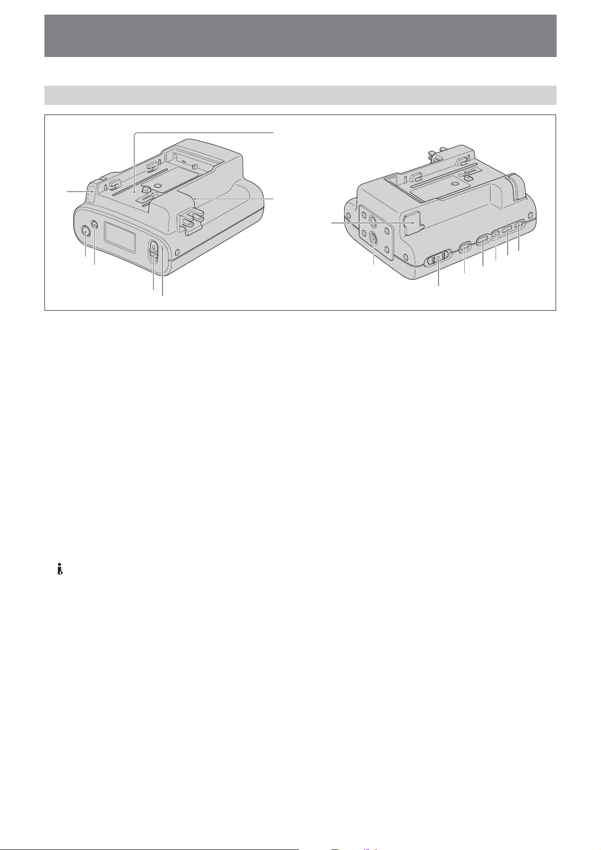
Hard Disk Recording Unit
7
1
2
3
4
5
1 BATT RELEASE button
Remove the battery pack from this unit by pressing the
BATT RELEASE button.
2 STOP button
Return to the VIDEO mode screen.
Stop recording or playback.
When a menu is selected, cancel it by pressing the STOP
button.
3 MENU/LCD BACK LIGHT button
Display the menu screen on the LCD screen.
Press the MENU/LCD BACK LIGHT button long enough
for the backlight of the LCD screen to come on or off.
4 REC switch
Start recording by sliding the REC switch.
5 REC lamp/Access lamp
REC lamp/Access lamp comes on during recording in
VIDEO mode.
REC lamp/Access lamp blinks while accessing the
computer in COMPUTER mode.
6 HDV/DV jack (6-pin)
Connect to a camcorder, computer etc. using the i.LINK
cable.
7 Battery slot
8 DC IN jack
Connect the power supply from an AC adaptor, etc.
9 Screw holes
You can use the supplied shoe adaptor to attach this unit
to a camcorder with a cold shoe or directly to a tripod.
q; POWER switch
Turn the power of this unit on or off.
Slide the POWER switch back and forth to select VIDEO,
COMPUTER or OFF.
6
8
qg
qf
9
qa
qs
qd
q;
qa CAM LINK button
Switch to CAM LINK [ON] (FOLLOW/SYNCHRO) to
record video in conjunction with the recording operation
of the camcorder, or to CAM LINK [OFF] to record with
this unit alone.
* Default setting is CAM LINK [ON].
qs REPEAT button
This changes the auto repeat mode.
Each time you press the button, the mode changes as
follows.
REPEAT1 (Repeatedly plays back the selected folder
only)/ ALL REPEAT (Repeatedly plays back all folders)/
OFF
qd PREVIOUS/REW button
Go back to the previous folder by pressing this button
during standby.
Press this button to stop playback and restart playback
from the beginning of the current file.
Keep this button pressed down during playback to play
the current file backwards at triple the normal speed.
When the menu screen is displayed on the LCD screen,
press this button to move the cursor.
qf PLAY/EXEC button
Play recorded files by pressing this button.
Pause playback by pressing this button.
When the menu screen is displayed on the LCD screen,
press this button to execute the selected menu item.
qg NEXT/FF button
Go to the next folder by pressing this button during
standby.
Press this button to stop playback and restart playback
from the beginning of the next file.
Keep this button pressed down during playback to play
the current file forwards at triple the normal speed.
When the menu screen is displayed on the LCD screen,
press this button to move the cursor.
6
Page 7
LCD screen display
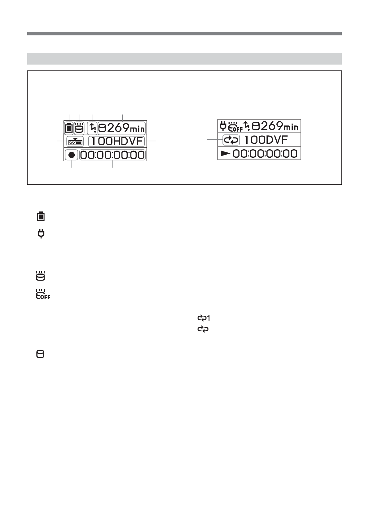
VIDEO mode
During recording During playback
12 3 4
56
78
1 Power supply display
Display the power supply icons.
Battery pack in use
Display the remaining battery capacity.
AC adapter connected
2 Drop detection mode display (3G sensor)
Display the operating state of the drop detection.
3G sensor ON
No icon Drop detection is not operating.
blinking Drop detection is operating.
3G sensor OFF
(Menu setting) lit Drop detection function is set to
OFF.
3 CAM LINK mode display
When the CAM LINK is set to ON, this icon is on.
When the CAM LINK is set to OFF, this icon is off.
4 Remaining hard disk capacity display
Display the remaining recording time (in minutes).
starts blinking in the following situations.
• When the remaining recording time is less than 5
minutes
• When the folder number is 999
• When using in a high temperature environment
9
6 Folder name display
Display the folder name in which the recording/playback
data is saved.
7 Status display
Display the status with an icon.
x Power is on and playback/recording is stopped
z Recording
N Playback
u Pausing playback
M Go to next file/fast-forward
m Back to the previous file/rewind
8 TC (time code) display
Display the time code.
9 Repeat mode display
Display the repeat status during playback.
REPEAT 1
REPEAT ALL
5 Cache recording mode display
Display the operating state of the cache recording mode
during recording.
When the cache recording mode is set to ON, this icon is
on.
When the cache recording mode is set to OFF, this icon is
off.
7
Page 8
Getting prepared
Preparing the power supply
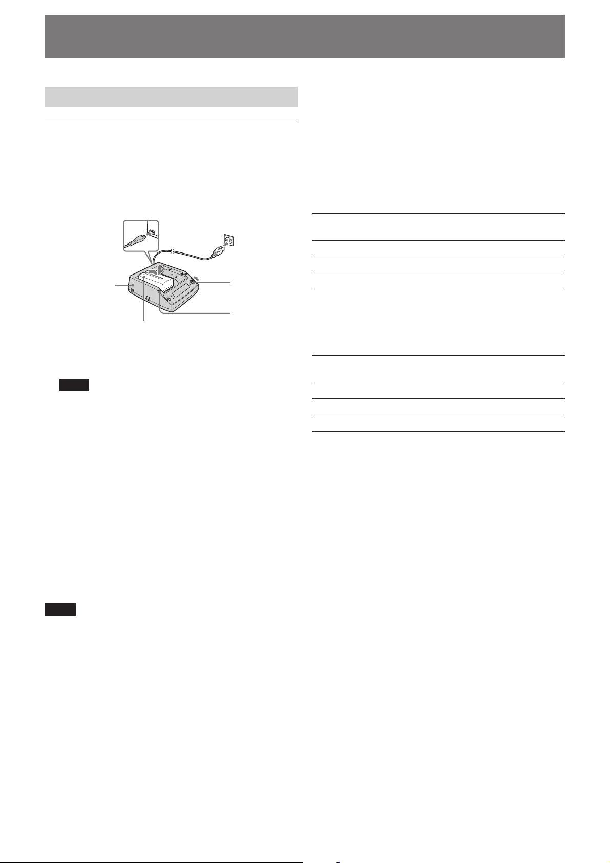
To charge the battery pack
When using an InfoLITHIUM battery pack (L-series,
optional) as the power supply for this unit, charge the battery
back as follows before use.
When charging the battery pack, refer to the operating
instructions supplied with the AC adaptor/charger
(optional).
2
3
44
1
AC adaptor/
charger ACVQ1050B
(optional)
Battery pack
Mode change
switch
CHARGE lamp
1 Set the mode change switch of the AC adaptor/
charger to CHARGE.
Note
You cannot charge when the mode change switch is set to
VCR/CAMERA.
2 Connect the AC power cord to the AC adaptor/
charger.
3 Connect the AC power cord to a wall outlet.
4 When installing the battery pack, press it down while
sliding it in the direction of the arrow.
Charging begins and the CHARGE lamp on the AC
adaptor/charger comes on.
When charging is completed, all of the segments of the
battery life indicator appear in the display window
(normal charge).
The CHARGE lamp goes off, but if you continue charging
until the “FULL” battery life indicator appears, the battery
capacity will be slightly longer (full charge).
5 When charging is completed, remove the battery pack
from the AC adaptor/charger.
Remaining battery time indication in the AC
adaptor/charger display window
This indication is provided by data communications between
the AC adaptor/charger and the InfoLITHIUM battery pack.
This unit does not have a data communications function, so
the displayed time may differ from the actual remaining time.
This is not a malfunction.
Charging time
Charging times for a completely exhausted InfoLITHIUM
battery pack (NP-F570, NP-F770, NP-F970) are as follows.
Battery pack Time for full (Time for normal
charge charge)
NP-F570 Approx. 145 minutes (Approx. 85 minutes)
NP-F770 Approx. 230 minutes (Approx. 170 minutes)
NP-F970 Approx. 310 minutes (Approx. 250 minutes)
Operating times for continuous recording
Operating times for continuous recording using an
InfoLITHIUM battery pack (NP-F570, NP-F770, NP-F970) are
as follows.
Battery pack Operating time (Operating time
from full charge from normal charge)
NP-F570 Approx. 330 minutes (Approx. 300 minutes)
NP-F770 Approx. 750 minutes (Approx. 680 minutes)
NP-F970 Approx. 1,080 minutes (Approx. 970 minutes)
Battery pack
Before changing the battery pack, slide the POWER switch to
OFF (CHG).
Charging/recording/playback time
• Times measured with the camcorder at 25°C (77°F)
(Recommended range is 10°C to 30°C (50°F to 86°F)).
• Recording and playback times are shorter at lower
temperatures.
• Recording and playback times are shorter depending on
the conditions of use of this unit.
• Except for the NP-F570/F770/F970, operating time is not
ensured.
Notes
• This unit can be used with an InfoLITHIUM battery pack
(L-series), but does not support the battery info function.
• This unit cannot be used to charge the battery pack
installed.
8
Page 9
AC adaptor/charger
Do not short-circuit the DC plug of the AC adaptor/charger
or battery terminal with any metallic objects. This may cause
a malfunction.
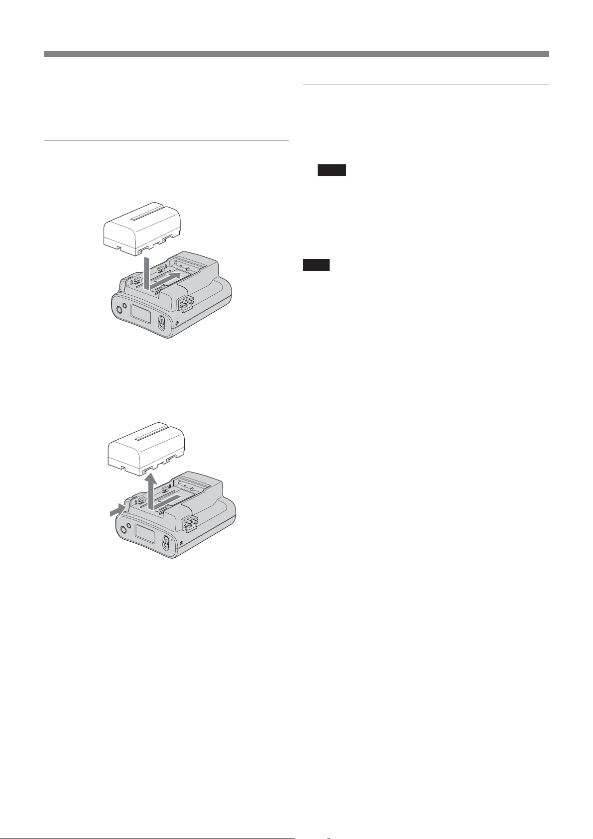
To install the battery pack to this unit
Slide the battery pack in the direction of the b mark on
the battery pack.
To remove the battery pack from this unit
Press the BATT RELEASE button of this unit and slide the
battery pack in the direction of the arrow.
To connect this unit to a wall outlet
For prolonged operation, such as playing the recorded
images, you can operate this unit from a domestic wall outlet
without worrying about battery life.
1 Set the mode change switch of the AC adaptor/
charger to VCR/CAMERA.
Note
When the mode change switch is set to CHARGE, there is
no power supply.
2 Connect the DK cable to the DC IN jack on this unit.
3 Connect the DK cable to the AC adaptor/charger.
4 With the power cord, connect the AC adaptor/charger
to a wall outlet.
Note
You can leave the battery pack installed while operating from
AC power. The power supply to the DC IN jack has priority.
To use the AC adaptor/charger from a vehicle
power supply
For details, refer to the operating instructions supplied with
the AC adaptor/charger.
9
Page 10

Using in VIDEO mode
2
Connecting this unit to a camcorder
As an example, the following steps and illustration show how
to connect this unit to an HVR-V1U/V1N/V1E/V1P digital
HD camcorder.
1 Attach the supplied shoe adaptor to this unit.
2 Attach this unit to the accessory shoe of the HVR-V1U/
V1N/V1E/V1P.
3 Connect the supplied i.LINK cable to the HDV/DV
jack on this unit and the
V1U/V1N/V1E/V1P.
4 Attach an optional battery pack (NP-F570/F770/F970)
to this unit.
HDV/DV jack on the HVR-
3
4
3
Menu settings
Check the individual settings and change them if necessary.
For details, see page 11.
1 Display the menu screen on the LCD screen by
pressing the MENU button.
2 Select the desired setting by pressing the PREVIOUS/
REW button or the NEXT/FF button and press the
PLAY/EXEC button.
3 Select the desired item by pressing the PREVIOUS/REW
button or the NEXT/FF button and press the PLAY/
EXEC button.
4 Return to the VIDEO mode screen by pressing the
STOP button.
1
2
2
Note
You cannot record or play back movies while the menu
screen is displayed on the LCD screen. Also, you cannot
change to the menu screen on the LCD screen during
recording or playback.
10
Page 11

Menu organization
PLAY MODE AUTO
CAM LINK SEL FOLLOW
CACHE REC OFF
DELETE LAST SHOT
TC FORMAT AUTO
DV FILE TYPE AVI
SLEEP MODE OFF
3G SENSOR ON
ALL RESET
* Boldface settings are default settings.
HDV
DV
SYNCHRO
ON
ALL
FORMAT
NDF
DF
RAW DV
ON
OFF
1 PLAY MODE
You can switch the playback format.
• AUTO ........Automatically switch the playback format
to the camcorder playback format.
• HDV...........Only play back the part recorded in HDV
format.
•DV..............Only play back the part recorded in
DVCAM (DV) format.
2 CAM LINK SEL
When CAM LINK is set to [ON], select the type of
camcorder-linked operation.
• FOLLOW......... Use this setting when connecting to a
camcorder that has no “external REC
control” function. The unit follows the
camcorder operation.
• SYNCHRO ...... Use this setting when connecting to a
camcorder that has an “external REC
control” function. The unit operates
simultaneously with the camcorder.
3 CACHE REC
You can set the cache recording mode to ON or OFF.
•ON.............Cache recording is enabled.
• OFF ............Cache recording is disabled.
4DELETE
You can delete recorded data or format this unit.
• LAST SHOT..... Delete the most recently recorded
folder.
• ALL ................... Deletes all folders recorded on this
unit.
Data in the user area is not deleted.
• FORMAT.......... Returns the hard disk to its default
state.
Data in the user area is deleted.
5 TC FORMAT
Follows the DF/NDF of the time code from the camcorder
connected to this unit.
• AUTO ........Follow the time code format of the
camcorder.
• NDF ...........Record the time code in NDF format.
•DF............... Record the time code in DF format.
Note
The default [AUTO] setting is NDF. If time code
information from the camcorder is not obtained, this unit
is set to the most recent recording setting.
11
Page 12

6 DV FILE TYPE
Changes the DV recording format.
• AVI.............Records video in AVI format.
• RAW DV ...Records video in DV format.
7 SLEEP MODE
You can set the sleep mode to ON or OFF.
•ON............. Sleep mode is set to ON.
• OFF ............Sleep mode is set to OFF.
When SLEEP MODE is set to [ON], if the i.LINK cable is
disconnected and nothing is displayed for 5 minutes or
more, this unit automatically switches to SLEEP status.
To return to normal status, reconnect the i.LINK cable to
this unit or turn the POWER switch off and then back on.
Note
In SLEEP MODE, this unit is not completely switched off
but continues to run using low power consumption.
8 3G SENSOR
You can set the drop sensor to ON or OFF.
•ON............. The 3G sensor of this unit tries to detect any
drop, and protects the hard disk if it detects
a drop. In this case, the icon will blink.
• OFF ............The 3G sensor does not operate so drop
detection is not performed.
Use this setting for recording in conditions
of continuous dropping such as on a roller
coaster or during sky diving.
Notes
• If a constant vibration is applied to this unit, recording
may stop. Recording data is therefore not guaranteed.
• When 3G SENSOR is set to OFF, the recording head is
not retracted. This may lead to damage.
• The 3G SENSOR is always set to ON when the power is
turned on.
9 ALL RESET
Restores all default settings.
12
Page 13

Recording images from the camcorder to this unit
Images recorded by the camcorder can be recorded onto this
unit.
Recording images (POWER switch at the VIDEO side)
The different methods of recording are as follows:
x Recording video simultaneously on this unit and
a camcorder
x Recording video on this unit while changing the
tape of the camcorder
x Recording video from this unit
x Operating cache recording
x Recording video simultaneously on this unit and
a camcorder
– Connecting to a camcorder with an “external REC
control” function (SYNCHRO mode)
When connected to a camcorder that has an external REC
control function, this unit can be controlled by the
camcorder to record video data simultaneously to the
camcorder recording on tape.
Camcorder
This unit
STANDBY REC STANDBY
REC
STANDBY REC STANDBY
STOP
1 Press the CAM LINK button of this unit and set it to
ON.
2 Set the [CAM LINK SEL] setting of this unit to
[SYNCHRO].
3 Set the [EXT REC CTRL] setting of the camcorder to
[SYNCHRONOUS].
4 Connect the camcorder to this unit via an i.LINK cable.
5 Press the REC START/STOP button of the camcorder to
start recording.
• The above Step 3 is for the HVR-V1U/V1N/V1E/V1P only.
For details on another camcorder you want to connect to
this unit, refer to the operating instructions supplied with
that camcorder.
• For details on the types of camcorder that have an “external
REC control” function and on motion detection, refer to the
“Guide to supported models and their functions” supplied
with this unit.
– Connecting to a camcorder without an “external
REC control” function (FOLLOW mode)
When connected to a camcorder that has no external REC
control function, this unit regularly checks the status of
the camcorder and follows its recording operation.
Camcorder
This unit
STANDBY REC STANDBY
STANDBY REC STANDBY
1 Press the CAM LINK button of this unit and set it to
ON.
2 Set the [CAM LINK SEL] setting of this unit to
[FOLLOW].
3 Connect the camcorder to this unit via an i.LINK cable.
4 Press the REC START/STOP button of the camcorder to
start recording.
Note
• This unit may lag up to two seconds behind the tape
recording/stopping point of the camcorder.
• For details on camcorders that have been tested in
FOLLOW mode, refer to “Guide to supported models
and their functions” supplied with this unit.
13
Page 14

x Recording video on this unit while changing the
tape of the camcorder
When connected to a camcorder that has an external REC
control function, you can record video on this unit only
while changing the tape or the camcorder, so that you do
not miss any important scenes.
5 minutes before end of tape
Camcorder
This unit
REC
STANDBY REC STANDBY
Changing the tape
REC
REC
STANDBY
STOP
1 Press the CAM LINK button of this unit and set it to
ON.
2 Set the [CAM LINK SEL] setting of this unit to
[SYNCHRO].
3 Set the [EXT REC CTRL] setting of the camcorder to
[RELAY].
4 Connect the camcorder to this unit via an i.LINK cable.
5 Press the REC START/STOP button of the camcorder to
start recording.
• When the remaining time of the tape is less than 5 minutes,
the camcorder sends a command to this unit to start
recording.
• The recording by this unit can be stopped from the
camcorder after changing the tape or by pressing the STOP
button of this unit.
• The noise of the tape change is recorded.
• The above Step 3 is for the HVR-V1U/V1N/V1E/V1P only.
For details on another camcorderyou want to connect to
this unit, refer to the operating instructions supplied with
that camcorder.
• For details on camcorders that have an external REC
control function and on motion detection, refer to the
“Guide to supported models and their functions” supplied
with this unit.
Cache recording mode
The most recent approximately maximum 14 seconds of
video and audio captured by the camcorder are held in a
buffer memory and automatically recorded on the hard disk
when the recording button is pressed. During this operation,
the time code of this unit is recorded.
To set the cache recording ON or OFF
Select CACHE REC on the menu screen and select the
desired setting ON or OFF.
• Any data of less than one frame is discarded.
• When CAM LINK [ON] is set, the data in the buffer
memory and the data recorded after starting recording are
recorded as separate files (in the same folder). In this case,
the time code of this unit is saved in the file recorded by
cache recording, and the time code of the camcorder is
saved in the file after cache recording.
• When you start recording by sliding the REC switch, the
data in the buffer memory and the data recorded after
starting recording are recorded as the same file. In this case,
the time code of this unit is saved in the file.
Notes
• If the i.LINK cable is disconnected or the power of the
connecting device turned off during recording, recording
stops but the data recorded until that point is recorded.
• If the power of this unit is turned off by battery exhaustion
or mistakenly sliding the POWER switch, the data recorded
until the power off is detected is recorded on this unit.
• If the battery pack is removed or the jack of the AC adaptor
disconnected during recording, the folder information at
the moment the power goes off may not be written
correctly.
x Recording video from this unit
You can use this unit to start or stop recording a video
input signal from an i.LINK without linked operation to a
device connected via i.LINK.
Camcorder
This unit
STANDBY REC STANDBY
STANDBY
REC REC REC STANDBY
REC
REC REC
STANDBY
1 Press the CAM LINK button of this unit and set it to
OFF.
2 Slide the REC switch to start recording.
14
Page 15

Playback the image from the camcorder
To play back video data recorded on this unit, you need to
connect this unit to a playback device via an i.LINK cable.
Playback (POWER switch to VIDEO)
The playback method is as follows.
• Standard playback
• Trick playback
• Repeat playback
To select the playback format
Select PLAY MODE on the menu screen and select the
desired setting, AUTO, HDV or DV.
For details on selecting the menu, see page 10.
– AUTO
Automatically switch the HDV/DV format signal during
playback.
– HDV
Only play back the part recorded in HDV format.
–DV
Only play back the part recorded in DVCAM (DV) format.
Standard playback
In this mode, the recorded file in this unit is output to the
i.LINK depending on the type of file.
To play back normally
Display the desired folder name on the LCD screen by
pressing . or >.
Play back the image by pressing the H button on this
unit.
Trick playback
When the playback file is output to i.LINK, the file is played
at triple the normal speed.
To play back at triple the normal speed
Keep pressing the . or > button during playback.
To play back in the forward direction, hold the > button
down. To play back in the backward direction, hold the .
button down.
Repeat playback
This unit can automatically repeat playback of all or one
folder in this unit.
To set repeat mode
Display or on the LCD screen by pressing the
REPEAT button on this unit.
– REPEAT 1
The recorded image in the desired folder is repeatedly
playback.
– ALL REPEAT
ALL REPEAT plays back all recorded images in this unit
to the last folder then goes back to the first folder and
repeats playback.
– OFF
When recorded images in the desired folder are played
back to the end, playback stops.
REPEAT mode
Folder name File name OFF REPEAT 1
Folder-A File A-1
File A-2
REPEAT ALL
File A-3
Folder-B File B-1
File B-2
File B-3
Folder-C File C-1
File C-2
File C-3
15
Page 16

Useful functions in combination
with HVR- V1U/V1N/V1E/V1P
Tapeless external REC control
You can start or stop recording video data on this unit by
pressing the REC START/STOP button of the HVR-V1U/
V1N/V1E/V1P without a tape in the HVR-V1U/V1N/V1E/
V1P.
Set the EXT REC CTRL setting of the HVR-V1U/V1N/
V1E/V1P as follows.
• REC CTL MODE ........ SYNCHRONUS or RELAY
• STBY COMMAND..... Desired setting
* For details, refer to the operating instructions for the
external REC control of the HVR-V1U/V1N/V1E/V1P.
You can record the time code of the HVR-V1U/V1N/V1E/
V1P without a tape in the HVR-V1U/V1N/V1E/V1P.
If you want to record video using the time code of
the HVR- V1U/V1N/V1E/V1P, set the time code
setting of the HVR- V1U/V1N/V1E/V1P as follows.
Time code value always advances.
• TC MAKE........ PRESET
• TC RUN........... FREE RUN
Time code value only advances during recording.
• TC MAKE........ PRESET
• TC RUN........... REC RUN
In combination with the time code settings of the HVR-V1U/
V1N/V1E/V1P, this unit operates as follows.
Set this unit as follows
• CAM LINK SEL.......... SYNCHRO
• Press the CAM LINK button to set to CAM LINK [ON].
TC MAKE
REGENERATE
PRESET
TC RUN
–
REC RUN
FREE RUN
Time code of this
unit with a tape in
the HVR-V1U/
V1N/V1E/V1P
When starting
recording on a tape,
video is recorded
using the time code
of the tape base.
If the time code of
the tape base can not
be read, the time
code starts from
00:00:00:00.
When starting
recording on a tape
or this unit, the time
code value advances
from the preset time
code of the HVRV1U/V1N/V1E/
V1P.
The preset time code
value advances
constantly and data
is recorded using the
data code.
Time code of this
unit without a tape
in the HVR-V1U/
V1N/V1E/V1P
The internal time
code of this unit
runs automatically.
When starting
recording on this
unit, the time code
value advances
from the preset time
code of the HVRV1U/V1N/V1E/
V1P.
The preset time
code value
advances constantly
and data is recorded
using the data code.
16
Page 17

Display the operational status of this unit on the HVR-V1U/V1N/V1E/V1P LCD screen
CAMERA mode
– Indicators
• The following information can be displayed on the LCD
screen of the HVR-V1U/V1N/V1E/V1P.
1
2
3
1 HDD connecting status
This icon is displayed when connecting this unit to the
HVR-V1U/V1N/V1E/V1P.
This icon blinks when an error occurs in this unit.
2 HDD mode
The same icon as the mode icon of this unit is displayed.
HDD mode Mode icon
STANDBY x
PLAY N
FF M
REW m
– Status check indicator
• The following information can be displayed on the status
check indicator (CAMERA mode) of the HVR-V1U/V1N/
V1E/V1P.
REC FORMAT
Displays the recording format of this unit.
STATUS
Displays the status (recording, playback etc.)
TIME CODE
Displays the time code during recording.
FOLDER
Displays the folder name during recording.
CAM LINK
Displays the CAM LINK status of this unit.
(When CAM LINK [OFF] is set, you cannot record from the
HVR-V1U/V1N/V1E/V1P.)
PLAY PAUSE u
REC z
3 3G sensor status
The following icon is displayed depending on the status
of the 3G sensor of this unit.
When drop detection is not operating: Icon is off.
During drop detection:
When drop detection function is OFF:
icon blinks.
icon is
displayed.
HDD REMAIN
Displays the HDD remaining recording time.
REMAIN
Displays the battery level.
(When connected to an AC adaptor/charger, “AC” is
displayed.)
17
Page 18

VCR mode
– Indicators
• The following information can be displayed on the LCD
screen of the HVR-V1U/V1N/V1E/V1P.
23
1
4
5
– Status check indicator
• The following information can be displayed on the status
check indicator (VCR mode) of the HVR-V1U/V1N/V1E/
V1P.
1 HDD connecting status
This icon is displayed when this unit is connected to the
HVR-V1U/V1N/V1E/V1P.
This icon blinks when an error occurs in this unit.
2 HDD mode
The same icon as the mode icon of this unit is displayed.
HDD mode Mode icon
STANDBY x
PLAY N
FF M
REW m
PLAY PAUSE u
REC z
3 3G sensor status
The following icon is displayed depending on the status
of the 3G sensor of this unit.
When drop detection is not operating: Icon is off.
During drop detection:
When drop detection function is OFF:
4 Time code of the playback signal of this unit
This time code is displayed during playback of a video
recorded by this unit.
5 Data code
This data code is displayed during playback of a video
recorded by this unit.
icon blinks.
icon is
displayed.
PB FORMAT
Displays the playback format of this unit.
STATUS
Displays the status (recording, playback etc.)
FOLDER
Displays the folder name during playback.
REPEAT MODE
Displays the playback mode. (“1” means “repeat 1 folder,”
“ALL” means “repeat all folders.”)
HDD REMAIN
Displays the HDD remaining recording time.
REMAIN
Displays the battery level.
(When this unit is connected to an AC adaptor/charger,
“AC” is displayed.)
18
Page 19

Using in COMPUTER mode
Connecting to a computer
You can transfer recorded images on this unit as a file in
HDV or DV format to a nonlinear editing system or
computer.
1 Attach the AC adaptor to this unit.
For extended use, using the AC adaptor is recommended.
This unit can still be operated even with the battery pack
attached.
2 Slide the POWER switch of this unit to COMPUTER.
3 Connect this unit to the computer via the supplied
i.LINK cable.
Note
This unit cannot receive power from the computer.
1
2
When this unit is set to COMPUTER mode, the following
screen is displayed on the LCD screen.
3
Computer requirements
For Windows users
• OS: Windows 2000 Professional (Service Pack 4 or later)/
Windows XP Home Edition (Service Pack 2 or later)/
Windows XP Professional (Service Pack 2 or later)
Standard installation is required.
Operation is not assured if the above OS has been
upgraded.
• CPU: MMX Pentium 200MHz or faster
For Macintosh users
• OS: Mac OS X (v10.3 or later)
19
Page 20

Folder saving format
Folder organization
The file/folder organization on the HDD of this unit is as follows.
USER
DVFVIDEO
DV
HDVF
HDV
100DVF
101DVF
999DVF
100HDVF
101HDVF
999HDVF
100DVF.IDX
DVS10001.AVI
100DVF.IDX
DVS10002.AVI
999DVF.IDX
DVS99901.DV
100HDVF.IDX
HDV10001.M2T
HDV10001.TS
100HDVF.IDX
HDV10002.M2T
HDV10002.TS
999HDVF.IDX
HDV99901.M2T
HDV99901.TS
Format
File number
01 - 99
HDV xxx xx .M2T
Folder number
100 - 999
Extension
When cache recording, a file of maximum 14 seconds is created at the top of the folder.
Files
The maximum file size is 4 GB. If a file size exceeds 4 GB, that file is automatically divided.
The last number of a new file name is automatically moved up one. When the last number of a file name exceeds 99, a new
folder is automatically created and the new file is saved in that folder.
HDVxxxxx.M2T
Data recorded in HDV format
When playback, HDV compatible playback software is
needed.
HDVxxxxx.TS
Ancillary data for the data recorded in HDV format
This data is needed for playback with this unit.
After this data is copied to a computer, it is not needed.
DVSxxxxx.AVI
DV format data recorded when DV FILE TYPE is set to
AVI
DVSxxxxx.DV
DV format data recorded when DV FILE TYPE is set to
RAW DV
For playback on Windows, Raw DV compatible playback
software is needed.
xxxHDVF.IDV or xxx.DVF.IDX
Information files of recording data in folders
(number of files, number of frames, starting time code,
etc.)
20
Page 21

HDD organization
Video area
• Up to 4.5 hours of video data can be recorded.
• Do not save the file.
Video area
User area
Notes
• Due to the limitations of Windows, this unit may not be detected when normal computer operation is restored after standby
or hibernation. For this reason, hibernation is not supported by this unit.
• Due to the specifications of Mac OS X, to disconnect this unit from a Mac with Mac OS X and connect it again, perform the
following steps.
• Do not transfer data from a computer to this unit in
COMPUTER mode.
Write back the data in VIDEO mode.
• Even if you delete or move files in COMPUTER mode, the
capacity of the HDD is not increased.
Delete data using this unit or format this unit.
User area
You can use up to about 1 GB of data freely in the user area.
To use a partition again
1 To use all the partitions of this unit, restart the computer or use Disk Utility. To use Disk Utility, follow the steps.
2 Start Disk Utility (/Applications/Utilities/).
3 Click the triangle mark on the left of the hard disk icon to display the hard disk volume and partition name.
4 Select one of the two grayed out partition names (“VIDEO” or “USER”). You do not need to select multiple grayed
out partition names.
5 Select [Mount] from the [Option] menu. The selected name “VIDEO” or “USER” is displayed on the desktop again.
(If it is still unmounted, select [Unmount] and then select [Mount] again.)
6 Exit Disk Utility.
21
Page 22

Trouble shooting
Please check the following before contacting your Sony dealer.
Note in case of repairs
• Some kinds of repair work may require that the hard disk be formatted or replaced. In either case, all data on the hard disk
will de deleted. Back-up your data from the hard disk before sending it for repairs. Sony does not guarantee against data
being deleted during repair work.
• During repair work, Sony may perform a minimal check of the data on a hard disk in order to verify improvements or the
occurrence of defective symptoms. However, Sony never copies or saves the data.
Power sources
Symptom Cause/Remedy
The camcorder gets warm.
The remaining battery time indicator
does not indicate the correct time.
The battery pack discharges too
quickly.
• This unit may get warmer while you use it. This is not a malfunction.
• The ambient temperature is too high or too low, or the battery pack has not been
charged enough. This is not a malfunction.
t Fully charge the battery pack again. If the problem persists, the battery pack
may be worn out. Replace it with a new one (p. 8).
• The indicated time may not be correct in certain circumstances.
• The ambient temperature is too high or too low, or the battery pack has not been
charged enough. This is not a malfunction.
t Fully charge the battery pack again. If the problem persists, the battery pack
may be worn out. Replace it with a new one (p. 8).
Recording
Symptom Cause/Remedy
Sliding the REC switch does not
record images.
• The POWER switch is set to COMPUTER.
t Slide the POWER switch to VIDEO (p. 6).
• This unit is recording the image you have just shot.
t Leave this unit for a while and then slide the REC switch.
• This unit is full.
t Delete unrequired images.
t Format this unit by selecting DELETE and then FORMAT.
• The temperature of this unit is extremely high.
t Turn off this unit and leave it for a while in a cool place.
• The temperature of this unit is extremely low.
t Leave this unit for a while with the POWER switch turned on. If you still
cannot operate this unit, turn it off and move it to a warm place. Leave this
unit there for a while and then turn it back on.
• The folder number shows 999 and the file number shows 9999.
t Delete unrequired images (p. 11) or format this unit by selecting DELETE and
then FORMAT.
• You may be unable to record images during drop detection.
22
Page 23

Symptom Cause/Remedy
The ACCESS lamp remains on even
when you stop recording.
Recording stops.
• This unit is recording the image you just shot.
t Do not remove the AC adaptor or the battery pack while the lamp is turned on.
• The temperature of this unit is extremely high.
t Turn off this unit and leave it for a while in a cool place.
• The temperature of this unit is extremely low.
t Turn off the unit and take it to a warm place. Leave it there for a while and then
turn it back on.
• The maximum continuous recordable time is approximately 4,5 hours.
• If you keep applying vibration to this unit, recording may stop.
• Fragmentation has occurred.
t Format this unit by selecting DELETE and then FORMAT.
Connecting a computer
Symptom Cause/Remedy
An error message appears when you
place the supplied CD-ROM in your
computer.
The image or sound on this unit
cannot be played back correctly.
The extension of a file is not
displayed on your computer.
t Set the computer display as follows:
– 1024 × 768 dots or more, high color (16 bits, 65,000 colors) or more.
• Depending on the computer you are using, the played back image or sound may
stop temporarily, but this does not affect the images or sound copied to your
computer.
• Playback software is not installed on your computer.
t Install playback software on your computer.
t To display the extension, follow the steps below.
1 In the window folder, click [Tools] t [Folder option...] t [View] tab.
2 Under Advanced Settings, uncheck [Hide file extensions for known file types].
3 Click [OK].
23
Page 24

Warning indicators
Self-diagnosis display
When an error occurs the following warning indicators may appear on the LCD screen.
Message Cause/Corrective Action
A:ss:ss/I:ss:ss/M:ss:ss/
X:ss:ss/F:ss:ss
(Self-diagnosis display)
If an error recurs after you repeat corrective action several times, contact Sony
Customer Service or the place of purchase.
A:11:ss
• Cannot read or write to the HDD.
t Turn this unit off and then back on.
A:19:ss
• Internal error has occurred.
t Turn this unit off and then back on.
I:11:ss
• i.LINK communication error has occurred.
t Turn this unit off and then back on.
I:92:ss
• Internal error has occurred.
t Turn this unit off and then back on.
M:11:ss
• The recorded image cannot be manipulated.
t Turn this unit off and then back on.
X:ss:ss
• Internal error has occurred.
t Turn this unit off and then back on.
F:12:ss
• There is a conflict in the HDD logic structure.
t Format this unit by selecting DELETE and then FORMAT.
If you still cannot operate the unit, contact Sony Customer Service.
F:29:ss
• There is an internal malfunction.
t Contact Sony Customer Service.
24
Page 25

Notes on using the hard disk drive
Save all your recorded image data
• In the case of your image data being damaged, save all
your recorded images. It is recommended that you use this
unit or your computer to save the image data on a tape or
DVD etc.
• It is recommended that you save your image data
periodically after recording.
Do not apply shock or vibration to this unit
• The hard disk of this unit may not be recognized, or
recording or playback may become disabled.
• In particular, do not apply shock during recording or
playback.
After recording, do not apply vibration or shock to this unit
while the ACCESS lamp is lit.
Drop detection
This unit has a drop detection function in order to protect the
internal hard disk from shock by dropping. If the unit is
dropped or enters a non-gravity state, a blocking noise to
protect this unit may also be recorded. If the drop detection
repeatedly detects dropping, recording/playback may be
stopped.
Notes on battery pack/AC adaptor
• Avoid the following while the ACCESS lamp is lit. Failure
to do so may cause malfunction.
– Removing the battery pack
– Removing the AC adaptor (while charging with the AC
adaptor)
• Always turn off the POWER switch before removing the
battery pack or the AC adaptor.
Note on operational temperature
If the temperature of this unit becomes extremely high or
extremely low, recording or playback may be disabled in
order to protect the unit. In such a case, a message appears on
the LCD screen.
Note on using this unit at altitude
Do not turn on this unit in a low-pressure environment (at an
altitude of 3,000 m (9,800 feet) or more).
Doing so may damage the hard disk drive of this unit.
Note on disposal/transfer
Even if you format this unit, the data may not be completely
deleted from the hard disk. Before transferring this unit to
another person, it is recommended that you make it difficult
to recover data by, for example, recording all black images on
this unit with the lens of the camcorder covered. Before
throwing this unit away, it is recommended that you destroy
the actual body in order to prevent data recovery from the
hard disk.
If you cannot record or play back images, format
this unit (FORMAT)
Repeated recording and deleting of images over a long period
of time can cause file fragmentation leading to incorrect
recording or saving of images.
25
Page 26

About i.LINK
The HDV/DV jack provided on this unit is an i.LINKcompliant jack. This section describes the i.LINK standard
and its features.
What is i.LINK?
i.LINK is a digital serial interface for sending and receiving
digital video, digital audio, and other data between this unit
and other equipment equipped with an i.LINK terminal. You
can also control other equipment using i.LINK.
i.LINK-compatible equipment can be connected using an
i.LINK cable. Possible applications are operations and data
exchange with various digital AV equipment.
When two or more i.LINK-compatible equipment are
connected to this unit, operations and data exchange are
possible with equipment directly connected to this unit and
also with equipment connected to this unit via other
equipment.
Note, however, that the method of operation may vary
depending on the characteristics and specifications of the
equipment to be connected. Also, there are cases where
operations and data exchange may not be possible even if the
connection is made.
Notes
• Normally, only one device can be connected to this unit
using i.LINK cable. When you connect this unit to HDV/
DVCAM (DV)-compliant equipment that allows multiple
connections, refer to the operating instructions of the
equipment to be connected.
• i.LINK is an easy-to-remember term for the IEEE 1394
proposed by Sony, and is a trademark approved by many
corporations in Japan and overseas.
• IEEE 1394 is an international standard standardized by the
Institute of Electrical and Electronics Engineers.
About the i.LINK baud rate
The maximum baud rate of i.LINK varies depending on the
equipment. There are three types.
S100 (Approximately 100 Mbps*)
S200 (Approximately 200 Mbps)
S400 (Approximately 400 Mbps)
The baud rate is listed under “Specifications” in the operating
instructions of individual equipment. It may be indicated
near the i.LINK interface on some equipment.
The baud rate may vary from the indicated value when this
unit is connected to equipment with a different maximum
baud rate.
To use i.LINK functions of this unit
For details on how to record data when this unit is connected
to a camcorder that has an i.LINK jack, see page 10.
This unit can also be connected to Sony i.LINK-compatible
devices other than camcorders (e.g. VAIO computers).
This unit may not be compatible with certain i.LINK video
devices such as digital televisions, DVD recorders/players
and MICROMV recorders/players even if they are equipped
with an i.LINK jack. Before connecting to another device,
confirm whether it is HDV/DVCAM (DV) compatible.
For precautions on connecting and the availability of
compatible software applications, refer to the operating
instructions of the device to be connected.
Notes
• When connecting an i.LINK cable to this unit or a
computer, check the direction of the jack. Forcibly inserting
the jack may damage the terminal or cause a malfunction.
Align the v mark on the i.LINK cable with the V mark next
HDV/DV jack before inserting the i.LINK cable.
to the
• Always connect the i.LINK cable to the computer first and
then to this unit. Connecting the i.LINK cable to this unit
first may cause this unit to malfunction because of static
electricity.
• When using an i.LINK cable to connect this unit to a device
equipped with an i.LINK jack, switch off the device and
remove the power cord from the AC outlet before
connecting or disconnecting the i.LINK cable. If the i.LINK
cable is connected or disconnected while the power cord of
the device is connected to the AC outlet, a high-voltage
current (8 to 40 V) output from the i.LINK jack of the device
will flow into this unit and damage it.
Required i.LINK cable
Use a Sony i.LINK cable.
i.LINK and
are trademarks of Sony Corporation.
* What is Mbps?
Mbps stands for “megabits per second,” or the volume of
data that can be sent or received in 1 second. For example, a
baud rate of 100 Mbps means that 100 megabits of data can
be sent in 1 second.
26
Page 27

Specifications
System
File system FAT32
Hard disk 60 GB
The capacity is the value when 1
GB equals 1 billion bytes.
The actual usable capacity may
be slightly less because
administrative files etc. are
included.
File format HDV recording MPEG-2TS
(.m2t)
DVCAM/DV recording
AVI-Type1
(.AVI)
RAW DV (.DV)
Input signal
HDV recording/playback Video: MPEG-2TS
Audio: MPEG1 Audio
Layer2 Stereo
DVCAM/DV recording/playback
Video: DV embedded
Audio: PCM digital
(12/16 bit, 32k, 48k)
Recording/playback time Approx. 270 minutes
General
Power requirement DC 7.2 V (battery pack)
DC 8.4 V (AC adaptor)
Power consumption 2.7 W
Operating temperature 0 °C to 40 °C (32 °F to 104 °F)
Storage temperature –20 °C to +60 °C (–4 °F to +140 °F)
Operating humidity 20 % (20 °C) to 90 % (35 °C)
(no condensation)
Operating altitude Maximum 3,000 m (9,843 feet)
Dimensions Approx. 81 × 45 × 100 mm
(w × h × d) (3 1/4 × 1 3/4 × 4 in.)
Mass Approx. 230 g (8 oz.)
Input/output jack i.LINK
(IEEE1394 6-pin connector S400)
Included items i.LINK cable (6-pin – 4-pin) 70 cm (1)
Operating Instructions (1)
Guide to supported models and
their functions(1)
CD-ROM manual (1)
Shoe adaptor (1)
Optional accessories AC adaptor/charger AC-VQ1050B
Battery pack NP-F570/F770/F970
Design and specifications are subject to change without
notice.
27
Page 28

Precautions
On use and care
• Do not use or store this unit and accessories in the
following locations.
– Anywhere extremely hot or cold. Never leave them
exposed to temperatures above 60 °C (140 °F), such as
under direct sunlight, near heaters or in a car parked in
the sun. They may malfunction or become deformed.
– Near strong magnetic fields or mechanical vibration. This
unit may malfunction.
– Near strong radio waves or radiation. This unit may not
be able to record properly.
– Near AM receivers and video equipment. Noise may
occur.
– On a sandy beach or anywhere dusty. If sand or dust gets
in this unit, it may malfunction. Sometimes this
malfunction cannot be repaired.
– Near windows or outdoors, where the LCD screen may
be exposed to direct sunlight. This damages the LCD
screen.
– Anywhere very humid.
• Operate this unit on DC 7.2 V (battery pack) or DC 8.4 V
(AC Adaptor).
• For DC or AC operation, use the accessories recommended
in these operating instructions.
• Do not let this unit get wet, for example, from rain or sea
water. If this unit gets wet, it may malfunction. Sometimes
this malfunction cannot be repaired.
• If any solid object or liquid gets inside the casing, unplug
this unit and have it checked by a Sony dealer before
operating it any further.
• Avoid rough handling, disassembling, modifying, physical
shock, or impact such as hammering, dropping or stepping
on this unit.
• Keep the POWER switch setting to OFF when you are not
using this unit.
• Do not wrap this unit with a towel, for example, and
operate it. Doing so might cause heat to build up inside.
• When disconnecting the mains lead, pull it by the plug and
not the lead.
• Do not damage the mains lead such as by placing anything
heavy on it.
• Keep metal contacts clean.
• If the battery electrolytic liquid has leaked,
– consult your local authorized Sony service facility.
– wash off any liquid that may have contacted your skin.
– if any liquid gets in your eyes, wash with plenty of water
and consult a doctor.
x To clean the LCD screen
If fingerprints or dust make the LCD screen dirty, it is
recommended you use a soft cloth to clean it. When you use
the LCD Cleaning Kit (optional), do not apply the cleaning
liquid directly to the LCD screen. Use cleaning paper
moistened with the liquid.
On handling the casing
• If the casing is soiled, clean this unit body with a soft cloth
lightly moistened with water, and then wipe the casing
with a dry soft cloth.
• Avoid the following to avoid damage to the finish.
– Using chemicals such as thinner, benzine, alcohol,
chemical cloths, repellent, insecticide and sunscreen.
– Handling with above substances on your hands.
– Leaving the casing in contact with rubber or vinyl objects
for a long period of time.
Note on use at high altitude
• Do not switch on this unit in a place which is at low
pressure (3,000 m or more above sea-level). Doing so may
damage the unit.
x When not using this unit for a long time
• Use up the battery pack completely before storing it.
LCD screen
• Do not exert excessive pressure on the LCD screen, as it
may cause damage.
• If this unit is used in a cold place, a residual image may
appear on the LCD screen. This is not a malfunction.
• While using this unit, the back of the LCD screen may heat
up. This is not a malfunction.
28
Page 29

Getting the best performance from the battery pack
• If the ambient temperature is low, the battery pack
performance deteriorates, reducing the operating time. To
maximize the operating time, the following techniques are
recommended.
– Keep the battery pack warm in a pocket, and load it into
the unit immediately before shooting.
• During recording or playback, power off whenever this
unit is not operating.
• Have enough batteries pack ready to last two or three times
the expected shooting duration, and test shoot with them
before the session.
• The battery pack is not waterproof. Be careful not to allow
it to get wet.
Indication of remaining battery pack capacity
If the battery pack fails even though the indication suggests
there is adequate capacity, fully recharge the battery pack.
This will correct the remaining capacity indication. However,
if the battery pack is used for a long time at high temperature,
is left fully charged, or has been very heavily used, the
indication may not be correctly restored. In this case, use the
indication time as a rough guideline to estimate the
remaining capacity.
Battery pack storage
• If the battery pack is not used for a long time, to maintain
its performance, it should be fully charged and then fully
discharged with this unit about once a year. Remove the
battery pack from this unit, and store in a cool dry place.
• To fully discharge the battery pack with this unit, leave it
powered on until the battery pack is exhausted.
Battery pack lifetime
• The battery pack has a limited lifetime. As it is repeatedly
used over a long time interval, the capacity gradually
reduces. When the operating time is much less than the
original value, it is time to replace the battery pack.
• The lifetime varies from one individual battery pack to
another, depending on the pattern of use, and how it has
been stored.
29
Page 30

Additional information on this product and answers to
frequently asked questions can be found at our Customer
Support Website.
 Loading...