

Sony hd1000j, hd1000u, hd1000n, hd1000e, hd1000p Service Manual
...
HVR-HD1000J/HD1000U/HD1000N/
HD1000E/HD1000P/HD1000C
SERVICE MANUAL
Ver. 1.3 2008.12
Revision History
Revision History
Revised-2
Replace the previously issued
SERVICE MANUAL 9-852-240-12
with this manual.
US Model
Canadian Model
AEP Model
E Model
Chinese Model
Japanese Model
N MECHANISM (MDX-N220)
Link
Link
SPECIFICATIONS
MODEL INFORMATION TABLE
SERVICE NOTE
DISASSEMBLY PRINTED WIRING BOARDS
The components identified by
mark 0 or dotted line with
mark 0 are critical for safety.
Replace only with part number specified.
Les composants identifiés par une
marque 0 sont critiques pour la
sécurité.
Ne les remplacer que par une pièce
portant le numéro spécifié.
BLOCK DIAGRAMS
FRAME SCHEMATIC DIAGRAMS
SCHEMATIC DIAGRAMS
REPAIR PARTS LIST
ADJUSTMENTS
INSTRUCTION MANUAL
HVR-HD1000J/HD1000U/HD1000N/HD1000E/HD1000P/HD1000C
DIGITAL HD VIDEO CAMERA RECORDER
2008L0500-1
Sony EMCS Co.
Published by Kohda TEC9-852-240-13
© 2008.12

These specifications are extracted
System
Video recording system (HDV)
2 rotary heads, Helical scanning system
Video recording system (DV)
2 rotary heads, Helical scanning system
Still image recording system
Exif Ver. 2.2*
1
Audio recording system (HDV)
Rotary heads, MPEG-1 Audio Layer -2 ,
Quantization: 16 bits (Fs 48 kHz, stereo)
transfer rate: 384 kbps
Audio recording system (DV)
Rotary heads, PCM system
Quantization: 12 bits (Fs 32 kHz, stereo 1,
stereo 2), 16 bits (Fs 48 kHz, stereo)
Video signal
PAL color, CCIR standards
1080/50i specification
Usable cassette
Mini DV cassette with the mark
printed
Tape speed (HDV)
Approx. 18.81 mm/s
Tape speed (DV)
SP: Approx. 18.81 mm/s
LP: Approx. 12.56 mm/s
Recording/playback time (HDV)
60 min (using a DVM60 cassette)
Recording/playback time (DV)
SP: 60 min (using a DVM60 cassette)
LP: 90 min (using a DVM60 cassette)
Fast forward/rewind time
Approx. 2 min 40 s (using a DVM60
cassette and rechargeable battery pack)
Approx. 1 min 45 s (using a DVM60
cassette and AC Adaptor)
Viewfinder
Electric viewfinder (color)
Image device
6.3 mm (1/2.9 type) CMOS sensor
Recording pixels (still, 4:3):
Max. 6.1 mega (2 848 × 2 136) pixels *
2
Gross: Approx. 3 200 000 pixels
Effective (movie, 16:9):
Approx. 2 280 000 pixels
Effective (movie, 4:3):
Approx. 1 710 000 pixels
Effective (still, 16:9):
Approx. 2 280 000 pixels
Effective (still, 4:3):
Approx. 3 040 000 pixels
Lens
Carl Zeiss Vario-Sonnar T
10 × (Optical), 20 × (Digital)
Focal length
f=5.4 ~ 54 mm (7/32 ~ 2 1/4 in.)
When converted to a 35 mm still camera
In TAPE: 40 ~ 400 mm (1 5/8 ~ 15 3/4 in.)
(16:9), 49 ~ 490 mm (1 15/16 ~ 19 3/8 in.)
(4:3)
In MEMORY: 40 ~ 400 mm (1 5/8 ~
15 3/4 in.) (16:9), 37 ~ 370 mm (1 1/2 ~
14 5/8 in.) (4:3)
F1.8 ~ 2.9
Filter diameter: 37 mm (1 1/2 in.)
Color temperature
[AUTO], [ONE PUSH], [INDOOR]
(3 200 K),
[OUTDOOR] (5 800 K)
Minimum illumination
5 lx (lux) ([AUTOSLW SHTR] [ON],
Shutter speed 1/25 sec)
0 lx (lux) (during NightShot function)
*1“Exif” is a file format for still images,
established by the JEITA (Japan Electronics
and Information Technology Industries
Association). Files in this format can have
additional information such as your
camcorder’s setting information at the time of
recording.
*2The unique pixel array of Sony’s ClearVid
CMOS sensor and image processing system
(new Enhanced Imaging Processor) allows
for still image resolution equivalent to the
sizes described.
Input/Output connectors
VIDEO OUT jack
Pin jack
1 Vp-p, 75 Ω (ohms)
S VIDEO OUT jack
4pin mini DIN
Luminance signal: 1 Vp-p, 75 Ω (ohms)
Chrominance signal: 0.3 Vp-p, 75 Ω (ohms)
AUDIO OUT jack
Pin jack
Audio signal: 327 mV (at load impedance
47 kΩ (kilohms)), Output impedance with
less than 2.2 kΩ (kilohms)
COMPONENT OUT jack
Y: 1 Vp-p, 75 Ω (ohms)
P
B/PR
, CB/CR: ± 350 mV, 75 Ω (ohms)
HDMI OUT jack
Type A (19-pin)
Headphone jack
Stereo minijack (Ø 3.5 mm)
LANC jack
Stereo mini-minijack (Ø 2.5 mm)
USB jack
B
MIC (PLUG IN POWER) jack
Stereo minijack (Ø 3.5 mm)
HDV/DV jack
i.LINK Interface (IEEE1394, 4-pin
connector S100)
LCD screen
Picture
6.7 cm (2.7 type, aspect ratio 16:9)
Total dot number
211 200 (960 × 220)
General
Power requirements
DC 7.2 V (battery pack)
DC 8.4 V (AC Adaptor)
Average power consumption
During camera recording using the
viewfinder with normal brightness:
HDV recording 4.4 W
DV recording 4.2 W
During camera recording using the LCD &
viewfinder with normal brightness:
HDV recording 4.8 W
DV recording 4.6 W
Operating temperature
0 °C to + 40 °C (32 °F to 104 °F)
Storage temperature
-20 °C to + 60 °C (-4 °F to + 140 °F)
Dimensions (approx.)
265 × 231 × 460 mm
(10 4/8 × 9 1/8 × 18 1/8 in.) (w/h/d)
including the projecting parts
265 × 231 × 460 mm
(10 4/8 × 9 1/8 × 18 1/8 in.) (w/h/d)
including the projecting parts with the
supplied battery pack NP-F570 attached
Mass (approx.)
2.7 kg (6 lb 0 oz) main unit only
3.0 kg (6 lb 10 oz) including the NP-F570
rechargeable battery pack and cassette
(PHDVM-63DM), and lens hood with lens
cover, microphone.
Supplied accessories
See page 5-35.
AC Adaptor AC-L100
Power requirements
AC 100 V - 240 V, 50/60 Hz
Current consumption
0.35 - 0.18 A
Power consumption
18 W
Output voltage
DC 8.4 V*
Operating temperature
0 °C to + 40 °C (32 °F to 104 °F)
Storage temperature
-20 °C to + 60 °C (-4 °F to + 140 °F)
Dimensions (approx.)
48 × 29 × 81 mm (1 15/16 × 1 3/16 ×
3 1/4 in.) (w/h/d) excluding the projecting
parts
Mass (approx.)
170 g (6.0 oz ) excluding the power cord
(mains lead)
* See the label on the AC Adaptor for other
specifications.
Rechargeable battery pack (NP-F570)
Maximum output voltage
DC 8.4 V
Output voltage
DC 7.2 V
Capacity
15.8 Wh (2 200 mAh)
Dimensions (approx.)
38.4 × 20.6 × 70.8 mm
(1 9/16 × 13/16 × 2 7/8 in.)
Mass (approx.)
100 g (3.5 oz)
Operating temperature
0 °C to + 40 °C (32 °F to 104 °F)
Type
Lithium ion
Design and specifications are subject to change
without notice.
from instruction manual of HVR-HD1000E/HD1000P.
SPECIFICATIONS
ENGLISH JAPANESE
ENGLISH JAPANESE
HVR-HD1000J/HD1000U/HD1000N/HD1000E/HD1000P/HD1000C
— 2 —

These specifications are extracted
System
Video recording system (HDV)
2 rotary heads, Helical scanning system
Video recording system (DV)
2 rotary heads, Helical scanning system
Still image recording system
Exif Ver. 2.2*
1
Audio recording system (HDV)
Rotary he ads, MPEG-1 Audio Layer -2 ,
Quantization: 16 bits (Fs 48 kHz, stereo)
transfer rate: 384 kbps
Audio recording system (DV)
Rotary heads, PCM system
Quantization: 12 bits (Fs 32 kHz, stereo 1,
stereo 2), 16 bits (Fs 48 kHz, stereo)
Video signal
NTSC color, EIA standards
1080/60i specification
Usable cassette
Mini DV cassette with the mark
printed
Tape speed (HDV)
Approx. 18.81 mm/s
Tape speed (DV)
SP: Approx. 18.81 mm/s
LP: Approx. 12.56 mm/s
Recording/playback time (HDV)
60 min (using a DVM60 cassette)
Recording/playback time (DV)
SP: 60 min (using a DVM60 cassette)
LP: 90 min (using a DVM60 cassette)
Fast forward/rewind time
Approx. 2 min 40 s (using a DVM60
cassette and rechargeable battery pack)
Approx. 1 min 45 s (using a DVM60
cassette and AC Adaptor)
Viewfinder
Electric viewfinder (color)
Image device
6.3 mm (1/2.9 type) CMOS sensor
Recording pixels (still, 4:3):
Max. 6.1 mega (2 848 × 2 136) pixels*
2
Gross: Approx. 3 200 000 pixels
Effective (movie, 16:9):
Approx. 2 280 000 pixels
Effective (movie, 4:3):
Approx. 1 710 000 pixels
Effective (still, 16:9):
Approx. 2 280 000 pixels
Effective (still, 4:3):
Approx. 3 040 000 pixels
Lens
Carl Zeiss Vario-Sonnar T
10 × (Optical), 20 × (Digital)
Focal length
f=5.4 ~ 54 mm (7/32 ~ 2 1/4 in.)
When converted to a 35 mm still camera
In TAPE: 40 ~ 400 mm (1 5/8 ~ 15 3/4 in.)
(16:9), 49 ~ 490 mm (1 15/16 ~ 19 3/8 in.)
(4:3)
In MEMORY: 40 ~ 400 mm (1 5/8 ~
15 3/4 in.) (16:9), 37 ~ 370 mm (1 1/2 ~
14 5/8 in.) (4:3)
F1.8 ~ 2.9
Filter diameter: 37 mm (1 1/2 in.)
Color temperature
[AUTO], [ONE PUSH], [INDOOR]
(3 200 K),
[OUTDOOR] (5 800 K)
Minimum illumination
5 lx (lux) ([AUTOSLW SHTR] [ON],
Shutter speed 1/30 sec)
0 lx (lux) (during NightShot function)
*1“Exif” is a file format for still images,
established by the JEITA (Japan
Electronics and Information Technology
Industries Association). Files in this format
can have additional information such as your
camcorder’s setting information at the time of
recording.
*2The unique pixel array of Sony’s ClearVid
CMOS sensor and image processing system
(new Enhanced Imaging Processor) allows for
still image resolution equivalent to the sizes
described.
Input/Output connectors
VIDEO OUT jack
Pin jack
1 Vp-p, 75 Ω (ohms)
S VIDEO OUT jack
4pin mini DIN
Luminance signal: 1 Vp-p, 75 Ω (ohms)
Chrominance signal: 0.286 Vp-p, 75 Ω
(ohms)
AUDIO OUT jack
Pin jack
Audio signal: 327 mV (at load impedance
47 kΩ (kilohms)), Output impedance with
less than 2.2 kΩ (kilohms)
COMPONENT OUT jack
Y: 1 Vp-p, 75 Ω (ohms)
P
B/PR
, CB/CR: ± 350 mV, 75 Ω (ohms)
HDMI OUT jack
Type A (19-pin)
Headphone jack
Stereo minijack (Ø 3.5 mm)
LANC jack
Stereo mini-minijack (Ø 2.5 mm)
USB jack
B
MIC (PLUG IN POWER) jack
Stereo minijack (Ø 3.5 mm)
HDV/DV jack
i.LINK Interface (IEEE1394, 4-pin connector
S100)
LCD screen
Picture
6.7 cm (2.7 type, aspect ratio 16:9)
Total dot number
211 200 (960 × 220)
General
Power requirements
DC 7.2 V (battery pack)
DC 8.4 V (AC Adaptor)
Average power consumption
During camera recording using the
viewfinder with normal brightness:
HDV recording 4.6 W
DV recording 4.4 W
During camera recording using the LCD &
viewfinder with normal brightness:
HDV recording 5.0 W
DV recording 4.8 W
Operating temperature
0 °C to + 40 °C (32 °F to 104 °F)
Storage temperature
-20 °C to + 60 °C (-4 °F to + 140 °F)
Dimensions (approx.)
265 × 231 × 460 mm
(10 4/8 × 9 1/8 × 18 1/8 in.) (w/h/d)
including the projecting parts
265 × 231 × 460 mm
(10 4/8 × 9 1/8 × 18 1/8 in.) (w/h/d)
including the projecting parts with the
supplied battery pack NP-F570 attached
Mass (approx.)
2.7 kg (6 lb 0 oz) main unit only
3.0 kg (6 lb 10 oz) including the NP-F570
rechargeable battery pack and cassette
(PHDVM-63DM), and lens hood with lens
cover, microphone.
Supplied accessories
See page 5-35.
AC Adaptor AC-L100
Power requirements
AC 100 V - 240 V, 50/60 Hz
Current consumption
0.35 - 0.18 A
Power consumption
18 W
Output voltage
DC 8.4 V*
Operating temperature
0 °C to + 40 °C (32 °F to 104 °F)
Storage temperature
-20 °C to + 60 °C (-4 °F to + 140 °F)
Dimensions (approx.)
48 × 29 × 81 mm (1 15/16 × 1 3/16 ×
3 1/4 in.) (w/h/d) excluding the projecting
parts
Mass (approx.)
170 g (6.0 oz ) excluding the power cord
(mains lead)
* See the label on the AC Adaptor for other
specifications.
Rechargeable battery pack (NP-F570)
Maximum output voltage
DC 8.4 V
Output voltage
DC 7.2 V
Capacity
15.8 Wh (2 200 mAh)
Dimensions (approx.)
38.4 × 20.6 × 70.8 mm
(1 9/16 × 13/16 × 2 7/8 in.) (w/h/d)
Mass (approx.)
100 g (3.5 oz)
Operating temperature
0 °C to + 40 °C (32 °F to 104 °F)
Type
Lithium ion
Design and specifications are subject to change
without notice.
from instruction manual of HVR-HD1000U/HD1000N.
SPECIFICATIONS
ENGLISH JAPANESE
ENGLISH JAPANESE
HVR-HD1000J/HD1000U/HD1000N/HD1000E/HD1000P/HD1000C
— 3 —

Ver. 1.3 2008.12
システム
録画方式
(
)
HDV
録画方式
)
(
DV
静止画記録方
式
録音方式
)
(
HDV
録音方式
(
)
DV
映像信号
使用可能カ
セット
テープ速度
)
(
HDV
テープ速度
)
(
DV
再生時
録画
/
間(
HDV
録画
再生時
/
間(
)
DV
早送り、
巻き戻し時間
ファインダー 電子ファインダー:カラー
撮像素子
ヘッドヘリカルスキャン
回転
2
回転
ヘッドヘリカルスキャン
2
Exif Ver.2.2*
回転ヘッド
MPEG-1 Audio Layer2
ビット
16
48kHz
転送レート
回転ヘッド
ビット
12
32kHz
(ステレオ1、ステレオ2)
ビット
16
48kHz
カラー、
NTSC
方式
1080/60i
マークのついたミニ
セット
約
18.812mm/
SP:約18.812mm/
LP:約12.555mm/
60分(DVM60
)
SP:60分(DVM60
LP:90分(DVM60
バッテリー使用時:
約
2分40秒(DVM60
アダプター使用時:
AC
約
1分45秒(DVM60
6.3mm(1/2.9型)CMOS
サー
記録画素数:静止画時最大
2
(
画素相当
*
モード)
3
総画素数:約
動画時有効画素数(
ド):約
228
動画時有効画素数(
万画素
約
171
静止画時有効画素数(
ド):約
228
静止画時有効画素数(
ド):約
304
1
384kbps
2848 × 2136)(4
320
万画素
万画素
万画素
(ステレオ)
(ステレオ)
標準方式
EIA
秒
秒
秒
使用時)
使用時)
使用時)
使用時)
使用時)
万画素
16:9
モード):
4:3
16:9
4:3
モー
モー
セン
610
DV
モー
ズームレンズ カール ツァイス バリオゾナー
色温度切り換え[
最低被写体照
度
カ
1
*
(社)電子情報技術産業協会(
2
*
T
倍(光学)、20倍(デジタル)
10
f=5.4〜54mm
カメラ換算では
35mm
」時:
「
TAP E
40〜400mm(16:9
(
モードでは49〜
4:3
「
MEMORY
40〜400mm(16:9
(
モードでは37〜
4:3
F1.8〜2.9
フィルター径
[、]
AUTO
[
INDOOR](3 200K
[
OUTDOOR](5 800K
5 lx
][ON[、]
SHTR
]
SPEED
1/30
0 lx
された、撮影情報などの付帯情報を追加する
ことができる静止画用のファイルフォーマッ
ト。
ソニー独自のクリアビッド
画素配列と画像処理システムエンハンスドイ
メージングプロセッサーにより、静止画は表
記の記載サイズを実現しています。
入/出力端子
VIDEO OUT
端子
S VIDEO
OUT
AUDIO
万
OUT
:
COMPONE
NT OUT
HDMI OUT
端子
ヘッドフォン端子ステレオミニジャック(
LANC
USB
ピン端子
1Vp-p、75
ピンミニ
4
端子
輝度信号:
色信号:
0.286Vp-p、75
ピンジャック
端子
音声:
327mV(47k
出力インピーダンス
Y:1Vp-p、75
端子
PB/PR. CB/C
コネクター
HDMI
端子 ステレオミニミニジャック
(
)
ø 2.5
端子 タイプ
B
」時:
37mm
ONE PUSH
[()スクル(
AUTOSLW
SHUTTR
秒)
()スクル(
NightShot
JEITA
CMOS
ǡ
DIN
1Vp-p、75
ǡ
:±
R
350mV、75
概略仕様
モード)
490mm
モード)
mm)
370
]、
)、
)
時)
)にて制定
センサーの
ǡ
ǡ
ǡ負荷時)、
ǡ以下
2.2k
ø 3.5
ステレオミニジャック(
)
端
i.LINK(IEEE1394 4
クター
6.7cm(2.7
)
16:9
211 200
横
960×縦220
)
MIC (PLUG
IN POWER
端子
HDV/DV
子
液晶画面
画面サイズ
総ドット数
電源部、その他
電源電圧 バッテリー端子入力
消費電力 ファインダー使用時、明るさ標
動作温度0℃〜40℃
保存温度 −
外形寸法
本体質量 約
撮影時総質量 約
付属品 5-36ページをご覧ください。
ǡ
)
端子入力
DC
準:
HDV
記録時
DV
液晶画面とファインダー使用時、
明るさ標準:
HDV
記録時
DV
20℃〜+60
265×231×460mm
奥行き)
265×231×460mm
(突起部含む、付属バッテリー
パック
2.7kg
3.0kg
テープ(
S100
型、アスペクト比
ドット
8.4V
記録時
4.6W
4.4W
記録時
5.0W
4.8W
NP-F570
(本体のみ)
(バッテリー
DVM60
)
℃
装着状態)
)含む。)
ENGLISH JAPANESE
ENGLISH JAPANESE
)
ø 3.5
ピンコネ
7.2V
NP-F570
アダプター
AC
電源
消費電力
定格出力
動作温度0℃〜40℃
保存温度 −
外形寸法 約
質量 約
その他の仕様についてはACアダプターのラ
*
ベルをご覧ください。
リチャージャブルバッテリーパック
NP-F570
最大電圧
公称電圧
容量
最大外形寸法 約
質量 約
使用温度0℃〜40℃
使用電池
本機の仕様および外観は、改良のため予告なく変
×さ高×幅()む含を部起突大最(
更することがありますが、ご了承ください。
、
AC100V〜240V、50Hz/60Hz
18W
DC8.4V *
20℃〜+60
48×29×81mm
をのぞく)(幅×高さ×奥行き)
170g
DC8.4V
DC7.2V
15.8Wh(2200mAh
38.4×20.6×70.8mm
(幅×高さ×奥行き)
100g
Li-ion
AC-L1 00
℃
(最大突起部
(本体のみ)
)
HVR-HD1000J/HD1000U/HD1000N/HD1000E/HD1000P/HD1000C
— 4 —

Ver. 1.3 2008.12
The changed portions from
Ver. 1.2 are shown in blue.
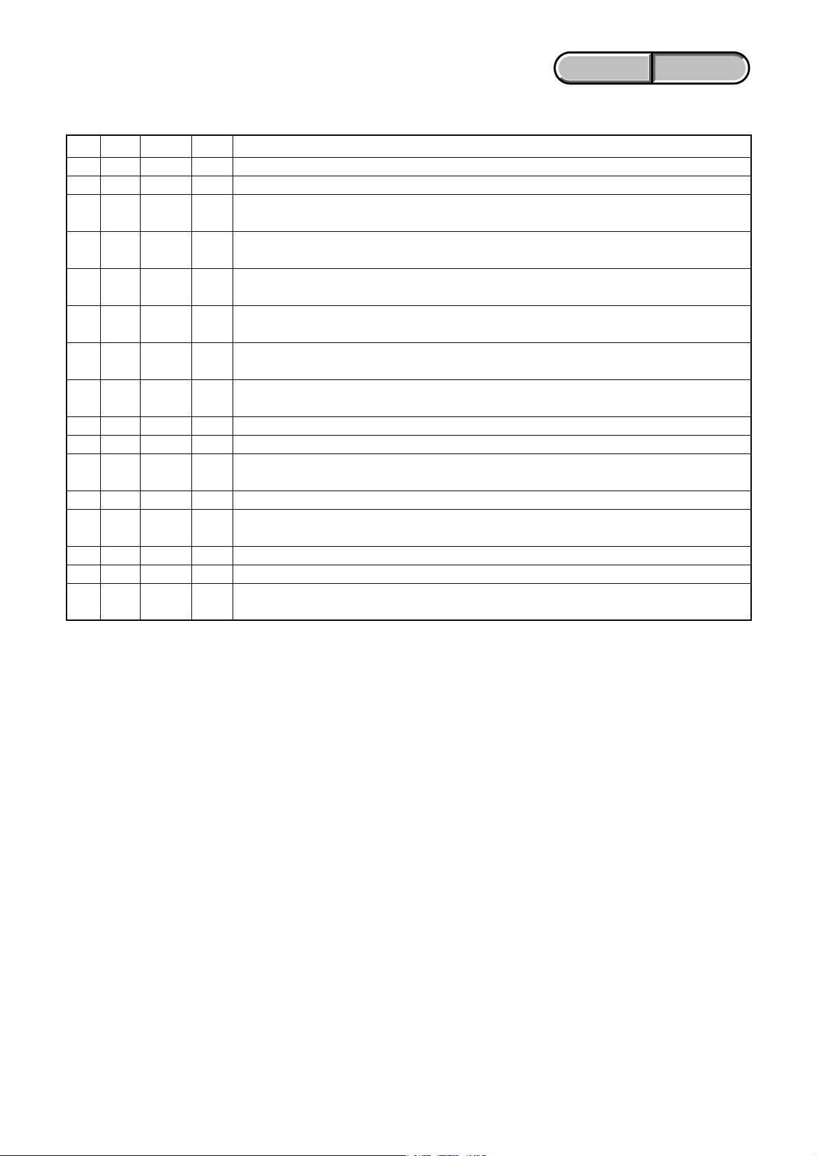
Model information table
Model HVR-HD1000J HVR-HD1000U HVR-HD1000N HVR-HD1000E HVR-HD1000P HVR-HD1000C
Destination J US, CND E AEP E CH
Color system NTSC NTSC NTSC PAL PAL PAL
•Abbreviation
AR : Argentine model
AUS: Australian model
BR : Brazilian model
CH : Chinese model
CND : Canadian model
EE : East European model
HK : Hong Kong model
J: Japanese model
JE : Tourist model
KR : Korea model
NE : North European model
HVR-HD1000J/HD1000U/HD1000N/HD1000E/HD1000P/HD1000C
— 5 —

ENGLISH JAPANESE
ENGLISH JAPANESE
Danger of explosion if battery is incorrectly replaced.
CAUTION
Replace only with the same or equivalent type.
SAFETY-RELATED COMPONENT WARNING!!
COMPONENTS IDENTIFIED BY MARK 0 OR DOTTED LINE WITH
MARK 0 ON THE SCHEMATIC DIAGRAMS AND IN THE PARTS
LIST ARE CRITICAL TO SAFE OPERATION. REPLACE THESE
COMPONENTS WITH SONY PARTS WHOSE PART NUMBERS
APPEAR AS SHOWN IN THIS MANUAL OR IN SUPPLEMENTS
PUBLISHED BY SONY.
SAFETY CHECK-OUT
After correcting the original service problem, perform the following
safety checks before releasing the set to the customer.
1. Check the area of your repair for unsoldered or poorly-soldered
connections. Check the entire board surface for solder splashes
and bridges.
2. Check the interboard wiring to ensure that no wires are
"pinched" or contact high-wattage resistors.
3. Look for unauthorized replacement parts, particularly
transistors, that were installed during a previous repair. Point
them out to the customer and recommend their replacement.
4. Look for parts which, through functioning, show obvious signs
of deterioration. Point them out to the customer and
recommend their replacement.
5. Check the B+ voltage to see it is at the values specified.
6. Flexible Circuit Board Repairing
•Keep the temperature of the soldering iron around 270˚C
during repairing.
• Do not touch the soldering iron on the same conductor of the
circuit board (within 3 times).
• Be careful not to apply force on the conductor when soldering
or unsoldering.
ATTENTION AU COMPOSANT AYANT RAPPORT
À LA SÉCURITÉ!
LES COMPOSANTS IDENTIFÉS PAR UNE MARQUE 0 SUR LES
DIAGRAMMES SCHÉMATIQUES ET LA LISTE DES PIÈCES SONT
CRITIQUES POUR LA SÉCURITÉ DE FONCTIONNEMENT. NE
REMPLACER CES COMPOSANTS QUE PAR DES PIÈSES SONY
DONT LES NUMÉROS SONT DONNÉS DANS CE MANUEL OU
DANS LES SUPPÉMENTS PUBLIÉS PAR SONY.
Unleaded solder
Boards requiring use of unleaded solder are printed with the leadfree mark (LF) indicating the solder contains no lead.
(Caution: Some printed circuit boards may not come printed with
the lead free mark due to their particular size.)
: LEAD FREE MARK
Unleaded solder has the following characteristics.
• Unleaded solder melts at a temperature about 40°C higher than
ordinary solder.
Ordinary soldering irons can be used but the iron tip has to be
applied to the solder joint for a slightly longer time.
Soldering irons using a temperature regulator should be set to
about 350°C.
Caution: The printed pattern (copper foil) may peel away if the
heated tip is applied for too long, so be careful!
• Strong viscosity
Unleaded solder is more viscous (sticky, less prone to flow) than
ordinary solder so use caution not to let solder bridges occur such
as on IC pins, etc.
•Usable with ordinary solder
It is best to use only unleaded solder but unleaded solder may
also be added to ordinary solder.
HVR-HD1000J/HD1000U/HD1000N/HD1000E/HD1000P/HD1000C
— 6 —
Ver. 1.3 2008.12
ENGLISH JAPANESE
ENGLISH JAPANESE
電池の交換は,正しく行わないと破裂する恐れがあり
注意
ます。電池を交換する場合には必ず同じ型名の電池
又は同等品と交換してください。
サービス,点検時には次のことにご注意下さい。
1. 注意事項をお守りください。
サービスのとき特に注意を要する個所については,
キャビネット,シャーシ,部品などにラベルや捺印で
注意事項を表示しています。これらの注意書き及び取
扱説明書等の注意事項を必ずお守り下さい。
2. 指定部品のご使用を
セットの部品は難燃性や耐電圧など安全上の特性を
持ったものとなっています。従って交換部品は,使用
されていたものと同じ特性の部品を使用して下さい。
特に回路図,部品表に0印で指定されている安全上重要
な部品は必ず指定のものをご使用下さい。
3. 部品の取付けや配線の引きまわしはもとどおりに
安全上,チューブやテープなどの絶縁材料を使用した
り,プリント基板から浮かして取付けた部品がありま
す。また内部配線は引きまわしやクランパによって発
熱部品や高圧部品に接近しないよう配慮されています
ので,これらは必ずもとどおりにして下さい。
4. サービス後は安全点検を
サービスのために取外したネジ,部品,配線がもとど
おりになっているか,またサービスした個所の周辺を
劣化させてしまったところがないかなどを点検し,安
全性が確保されていることを確認して下さい。
5. チップ部品交換時の注意
• 取外した部品は再使用しないで下さい。
• タンタルコンデンサのマイナス側は熱に弱いため交
換時は注意して下さい。
6. フレキシブルプリント基板の取扱いについて
• コテ先温度を270℃前後にして行なって下さい。
• 同一パターンに何度もコテ先を当てないで下さい。
(3回以内)
• パターンに力が加わらないよう注意して下さい。
7. 無鉛半田について
無鉛半田を使用している基板には,無鉛(LeadFree)を意
味するレッドフリーマークがプリントされています。
(注意:基板サイズによっては,無鉛半田を使用して
いてもレッドフリーマークがプリントされて
いないものがあります)
:レッドフリーマーク
無鉛半田には,以下の特性があります。
• 融点が従来の半田よりも約40℃高い。
従来の半田こてをそのまま使用することは可能です
が,少し長めにこてを当てる必要があります。
温度調節機能のついた半田こてを使用する場合,約
350℃に設定して下さい。
注意: 半田こてを長く当てすぎると,基板のパター
ン(銅箔)がはがれてしまうことがあります
ので,注意して下さい。
• 粘性が強い
従来の半田よりも粘性が強いため,IC端子などが半田
ブリッジしないように注意して下さい。
• 従来の半田と混ぜて使用可能
無鉛半田には無鉛半田を追加するのが最適ですが,
従来の半田を追加しても構いません。
HVR-HD1000J/HD1000U/HD1000N/HD1000E/HD1000P/HD1000C
— 7 —
y
ENGLISH JAPANESE
1. SERVICE NOTE
ENGLISH JAPANESE
1-1. POWER SUPPLY DURING REPAIRS
In this unit, about 10 seconds after power is supplied to the battery terminal using the regulated power supply (8.4 V), the power is shut off so
that the unit cannot operate.
These following method is available to prevent this.
Method:
Use the AC power adaptor (AC-L100).
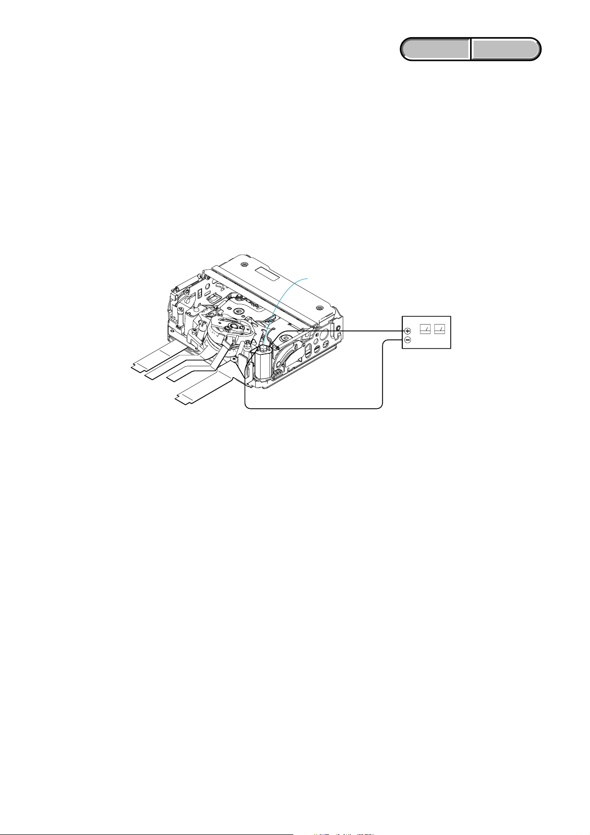
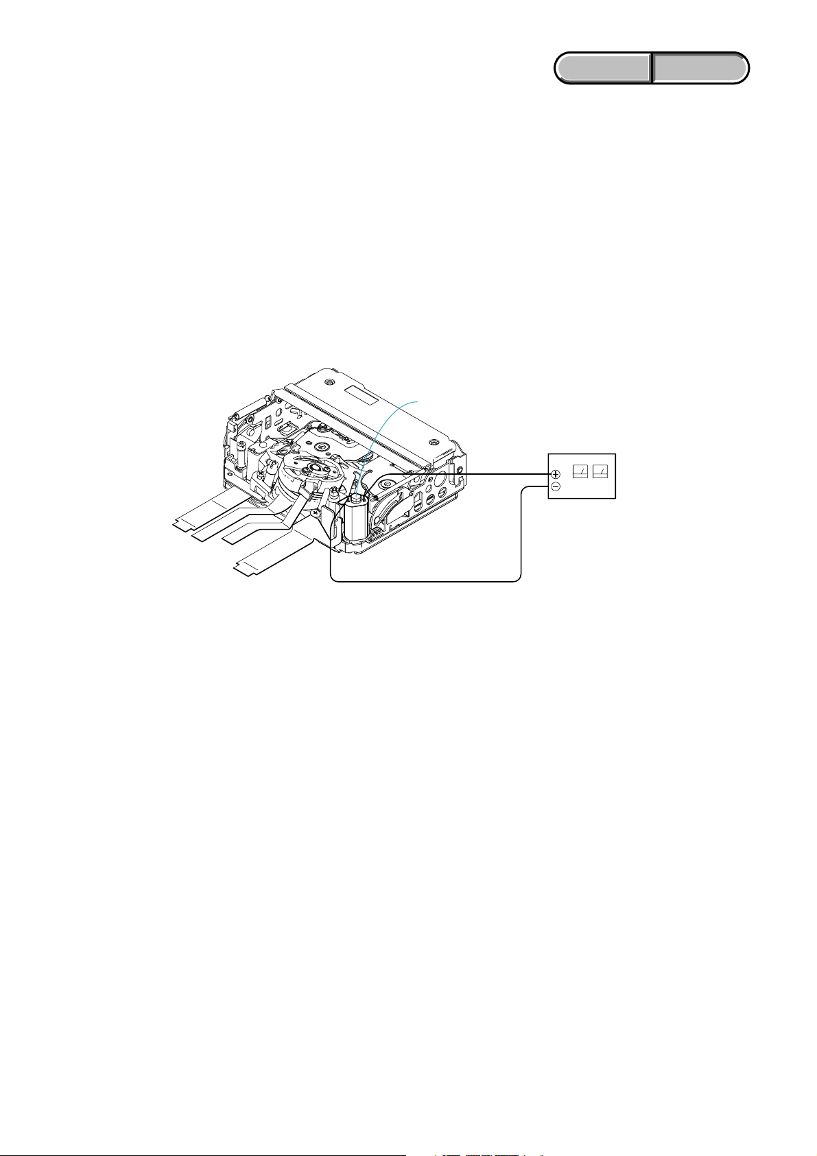
1-2. TO TAKE OUT A CASSETTE WHEN NOT EJECT (FORCE EJECT)
1 Refer to “2. DISASSEMBLY” to remove the mechanism deck block.
2 Supply +4.5 V from the DC power supply to the loading motor and unload with a pressing the cassette compartment.
Loading motor
DC power suppl
(+ 4.5 Vdc)
1-3. SETTING THE “FORCED POWER ON” MODE
It is possible to turn on power by adjustment remote commander (RM-95 or NEW LANC JIG).
Operate the VTR function using the adjustment remote commander.
1-3-1. Setting the “Forced Camera Power ON” Mode
1) Select page: 0, address: 01, and set data: 01.
2) Select page: A, address: 10, set data: 01 and press the “PAUSE (Write) ” button of the adjustment remote commander.
1-3-2. Setting the “Forced VTR Power ON” Mode
1) Select page: 0, address: 01, and set data: 01.
2) Select page: A, address: 10, set data: 02 and press the “PAUSE (Write) ” button of the adjustment remote commander.
1-3-3. Exiting the “Forced Power ON” Mode
1) Select page: 0, address: 01, and set data: 01.
2) Select page: A, address: 10, set data: 00 and press the “PAUSE (Write) ” button of the adjustment remote commander.
3) Select page: 0, address: 01, and set data: 00.
HVR-HD1000J/HD1000U/HD1000N/HD1000E/HD1000P/HD1000C
1-1
ENGLISH JAPANESE
ENGLISH JAPANESE
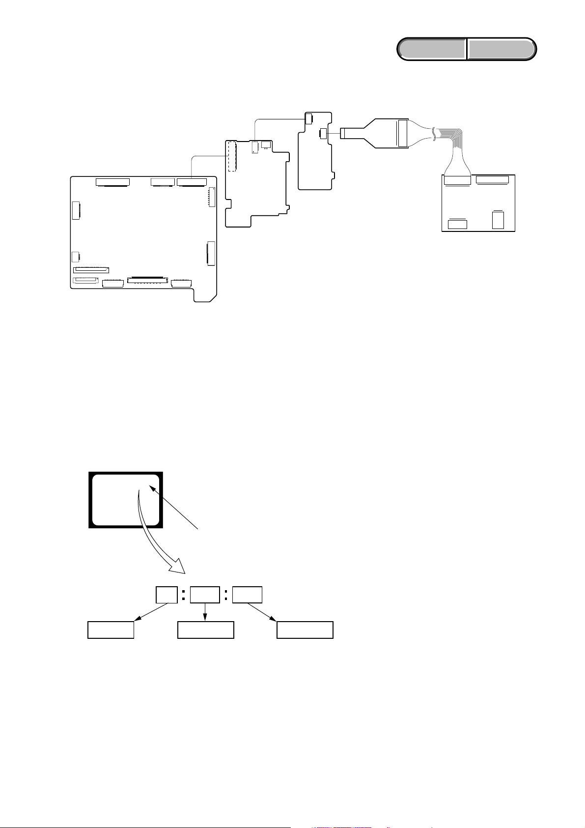
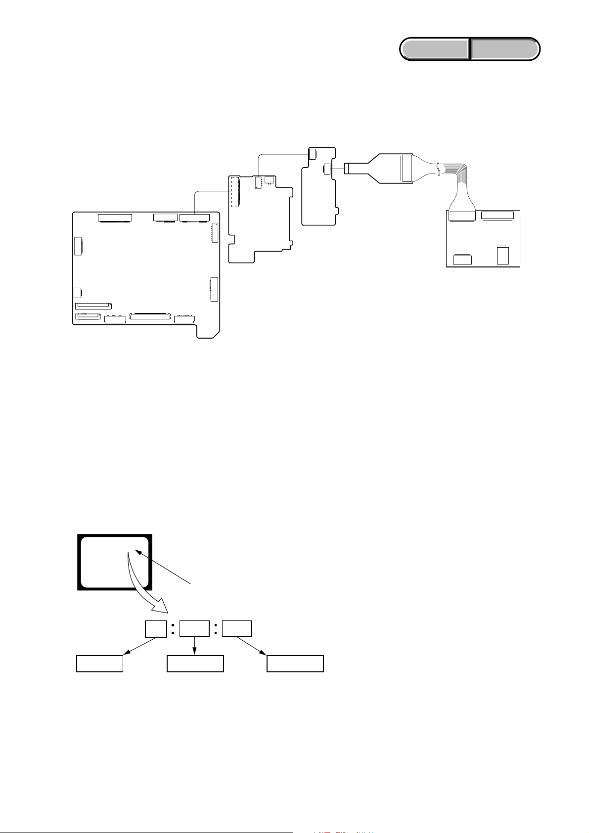
1-4. USING SERVICE JIG
Connect the CPC-15 jig connector (J-6082-564-A) and I/F unit for LANC control (J-6082-521-A) to the CN8102 on the US-014 board.
CPC-15
(J-6082-564-A)
8
1
I/F unit for LANC control
(J-6082-521-A)
VC-500 BOARD
(SIDE A)
CN1012
FP-786 Flexible
FLexible Flat Cable (FFC-107)
CN8003
CN8001 (SIDE B)
MS-379 BOARD
(SIDE A)
CN8101
8
1
CN8102
US-014 BOARD
(SIDE A)
1-5. SELF-DIAGNOSIS FUNCTION
1-5-1. Self-diagnosis Function
When problems occur while the unit is operating, the self-diagnosis
function starts working, and displays on the viewfinder or LCD
screen what to do.
Details of the self-diagnosis functions are provided in the Instruction
manual.
Viewfinder or LCD screen
C : 3 1 : 1 1
Blinks at 3.2Hz
1 1
Refer to “1-5-3. Self-diagnosis Code Table”.
Repaired by:
C : Corrected by customer
H : Corrected by dealer
E : Corrected by service
engineer
3 1C
Block
Indicates the appropriate
step to be taken.
E.g.
31 ....Reload the tape.
32 ....Turn on power again.
1-5-2. Self-diagnosis Display
When problems occur while the unit is operating, the counter of the
viewfinder or LCD screen shows a 4-digit display consisting of an
alphabet and numbers, which blinks at 3.2 Hz. This 5-character
display indicates the “repaired by:”, “block” in which the problem
occurred, and “detailed code” of the problem.
Detailed Code
HVR-HD1000J/HD1000U/HD1000N/HD1000E/HD1000P/HD1000C
1-2
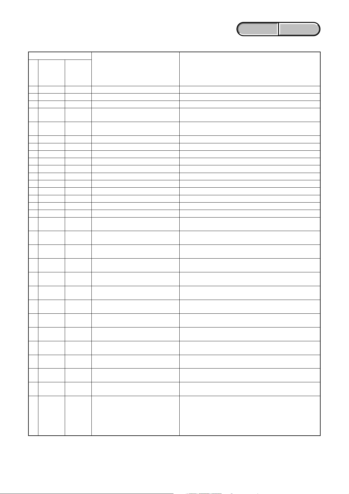
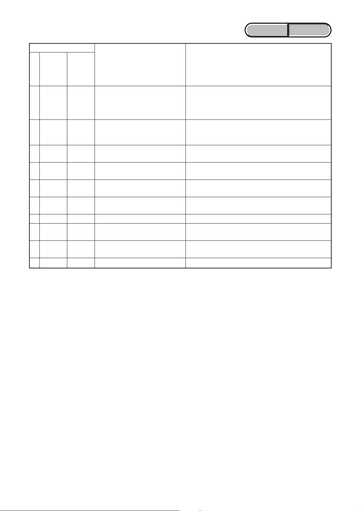
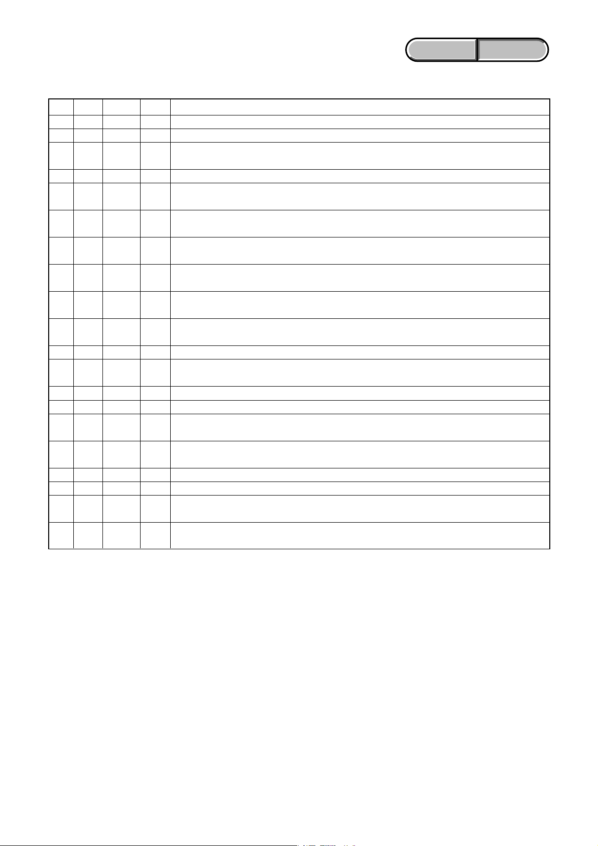
1-5-3. Self-diagnosis Code Table
Self-diagnosis Code
ENGLISH JAPANESE
ENGLISH JAPANESE
Repaired by:
C
C
C
C
C
C
C
C
C
C
C
C
C
C
C
C
C
C
C
C
C
C
C
C
C
C
C
C
C
C
Block
Function
04
21
22
31
31
31
31
31
31
31
31
31
31
31
31
31
32
32
32
32
32
32
32
32
32
32
32
32
32
32
Detailed
Code
00
00
00
10
11
20
21
22
23
30
31
40
41
42
43
44
10
11
20
21
22
23
30
31
40
41
42
43
44
60
Symptom/State
Non-standard battery is used.
Condensation.
Video head is dirty.
LOAD direction. Loading does not
complete within specified time
UNLOAD direction. Loading does not
complete within specified time
T reel side tape slacking when unloading
S reel
side tape slacking when unloading
T reel fault.
S reel fault.
FG fault when starting capstan.
FG fault during normal capstan operations.
FG fault when starting drum.
PG fault when starting drum.
FG fault during normal drum operations.
PG fault during normal drum operations.
Phase fault during normal drum operations.
LOAD direction loading motor time-
out.
UNLOAD direction loading motor
time-out.
T reel side tape slacking when
unloading.
S reel side tape slacking when
unloading.
T reel fault.
S reel fault.
FG fault when starting capstan.
FG fault during normal capstan
operations.
FG fault when starting drum.
PG fault when starting drum.
FG fault during normal drum
operations.
PG fault during normal drum
operations.
Phase fault during normal drum
operations.
Difficult to adjust focus.
(Cannot initialize focus.)
.
Correction
Use the InfoLITHIUM battery.
Remove the cassette, and insert it again after one hour.
Clean with the optional cleaning cassette.
Load the tape again, and perform operations from the beginning.
Load the tape again, and perform operations from the beginning.
Load the tape again, and perform operations from the beginning.
.
Load the tape again, and perform operations from the beginning.
Load the tape again, and perform operations from the beginning.
Load the tape again, and perform operations from the beginning.
Load the tape again, and perform operations from the beginning.
Load the tape again, and perform operations from the beginning.
Load the tape again, and perform operations from the beginning.
Load the tape again, and perform operations from the beginning.
Load the tape again, and perform operations from the beginning.
Load the tape again, and perform operations from the beginning.
Load the tape again, and perform operations from the beginning.
Remove the battery or power cable, connect, and perform
operations from the beginning.
Remove the battery or power cable, connect, and perform
operations from the beginning.
Remove the battery or power cable, connect, and perform
operations from the beginning.
Remove the battery or power cable, connect, and perform
operations from the beginning.
Remove the battery or power cable, connect, and perform
operations from the beginning.
Remove the battery or power cable, connect, and perform
operations from the beginning.
Remove the battery or power cable, connect, and perform
operations from the beginning.
Remove the battery or power cable, connect, and perform
operations from the beginning.
Remove the battery or power cable, connect, and perform
operations from the beginning.
Remove the battery or power cable, connect, and perform
operations from the beginning.
Remove the battery or power cable, connect, and perform
operations from the beginning.
Remove the battery or power cable, connect, and perform
operations from the beginning.
Remove the battery or power cable, connect, and perform
operations from the beginning.
Remove the battery or power cable, connect, and perform
operations from the beginning.
If it does not recover, inspect the focus MR sensor of lens block
(Pin qh, qk of CN5301 on the LD-229 board).
If not faulty, inspect the focus motor drive circuit
(IC5404 on the LD-229 board).
HVR-HD1000J/HD1000U/HD1000N/HD1000E/HD1000P/HD1000C
1-3
Ver. 1.3 2008.12
The changed portions from
Ver. 1.2 are shown in blue.
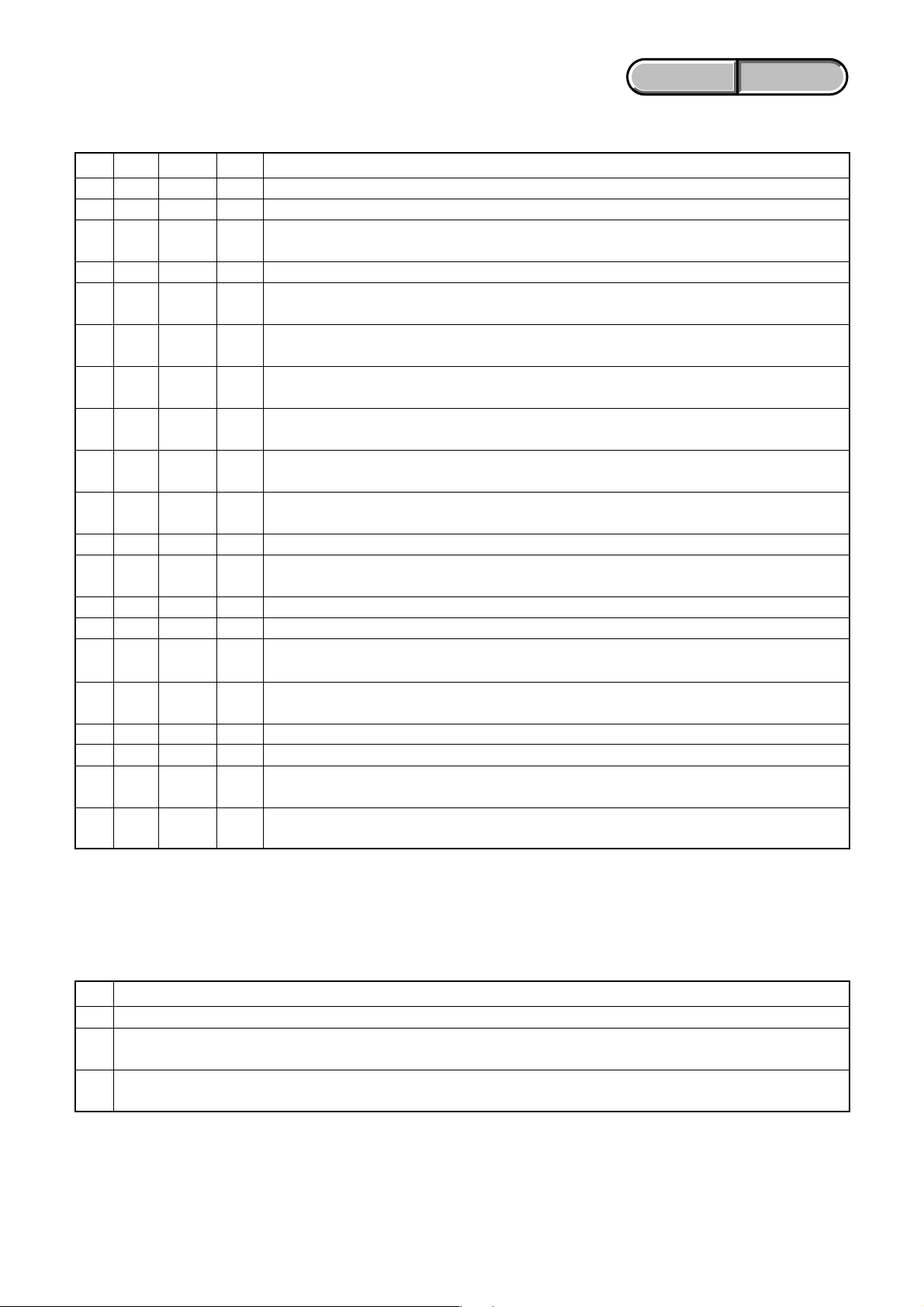
Self-diagnosis Code
ENGLISH JAPANESE
ENGLISH JAPANESE
Repaired by:
E
E
E
E
E
E
E
E
E
E
Block
Function
61
61
62
62
62
62
62
62
62
62
Detailed
Code
10
11
00
01
02
03
10
11
12
20
Symptom/State
Zoom operations fault.
(Cannot initialize zoom lens.)
Focus lens initializing failure and zoom
lens initializing failure occur
simultaneously.
Steadyshot function does not work well.
(With pitch angular velocity sensor output
stopped.)
Steadyshot function does not work well.
(With yaw angular velocity sensor output
stopped.)
Abnormality of IC for steadyshot.
IC for steadyshot and micro controller
communication abnormality among.
Shift lens initializing failure.
Shift lens overheating (Pitch).
Shift lens overheating (Yaw).
Abnormality of thermistor.
Correction
Inspect the zoom MR sensor of lens block (Pin w;, wa of CN5301
on the LD-229 board) when zooming is performed when the zoom
switch is operated and the zoom motor drive circuit (IC5404 on
the LD-229 board) when zooming is not performed.
Check both C: 32: 60 and E: 61: 10 of the self-diagnosis code.
Inspect pitch angular velocity sensor (SE7202 on the CM-077
board) peripheral circuits.
Inspect yaw angular velocity sensor (SE7201 on the CM-077
board) peripheral circuits.
Refer to [1-6-1. E : 62 : 02 (Abnormality of IC for Steadyshot)
Occurred].
Inspect the steadyshot circuit (IC5703 on the LD-229 board).
Refer to [1-6-2. E : 62 : 10 (Shift Lens Initializing Failure)
Occurred].
Refer to [1-6-3. E : 62 : 11 (Shift Lens Overheating (Pitch))
Occurred].
Refer to [1-6-4. E : 62 : 12 (Shift Lens Overheating (Yaw))
Occurred].
Refer to [1-6-5. E : 62 : 20 (Abnormality of Thermistor)
Occurred].
HVR-HD1000J/HD1000U/HD1000N/HD1000E/HD1000P/HD1000C
1-4
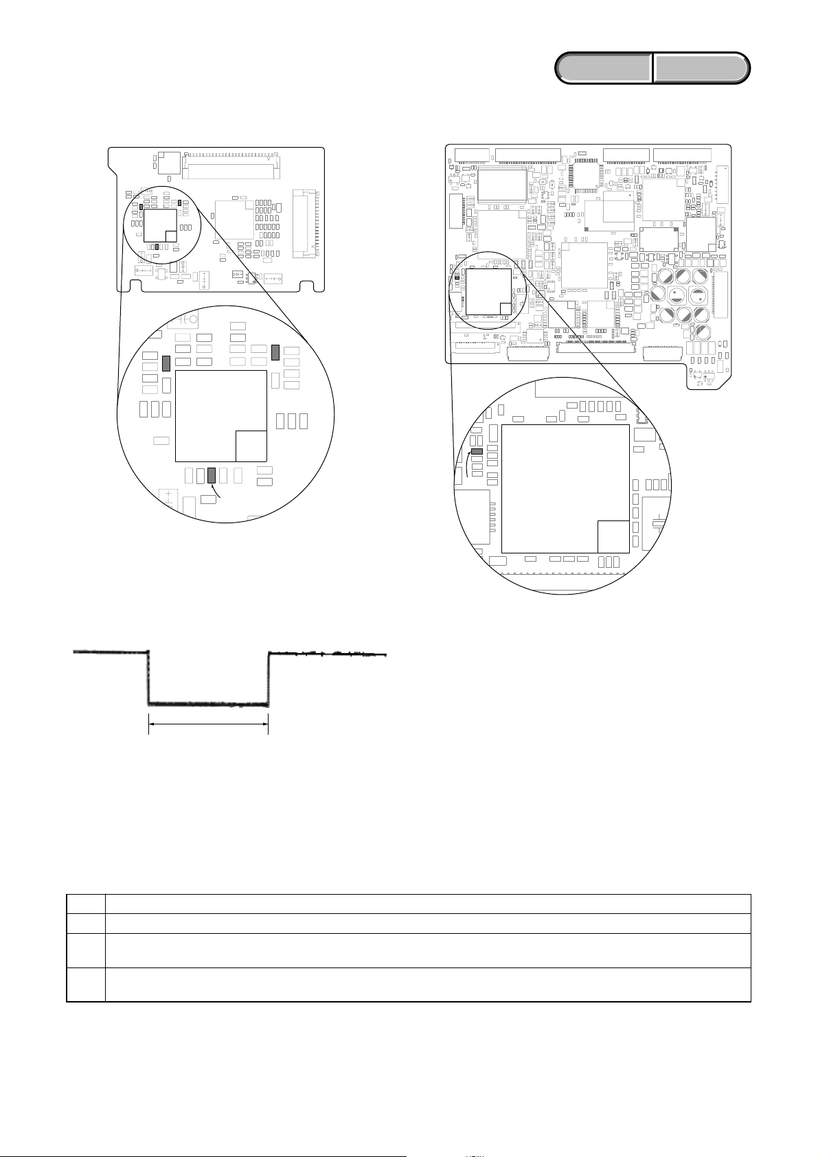
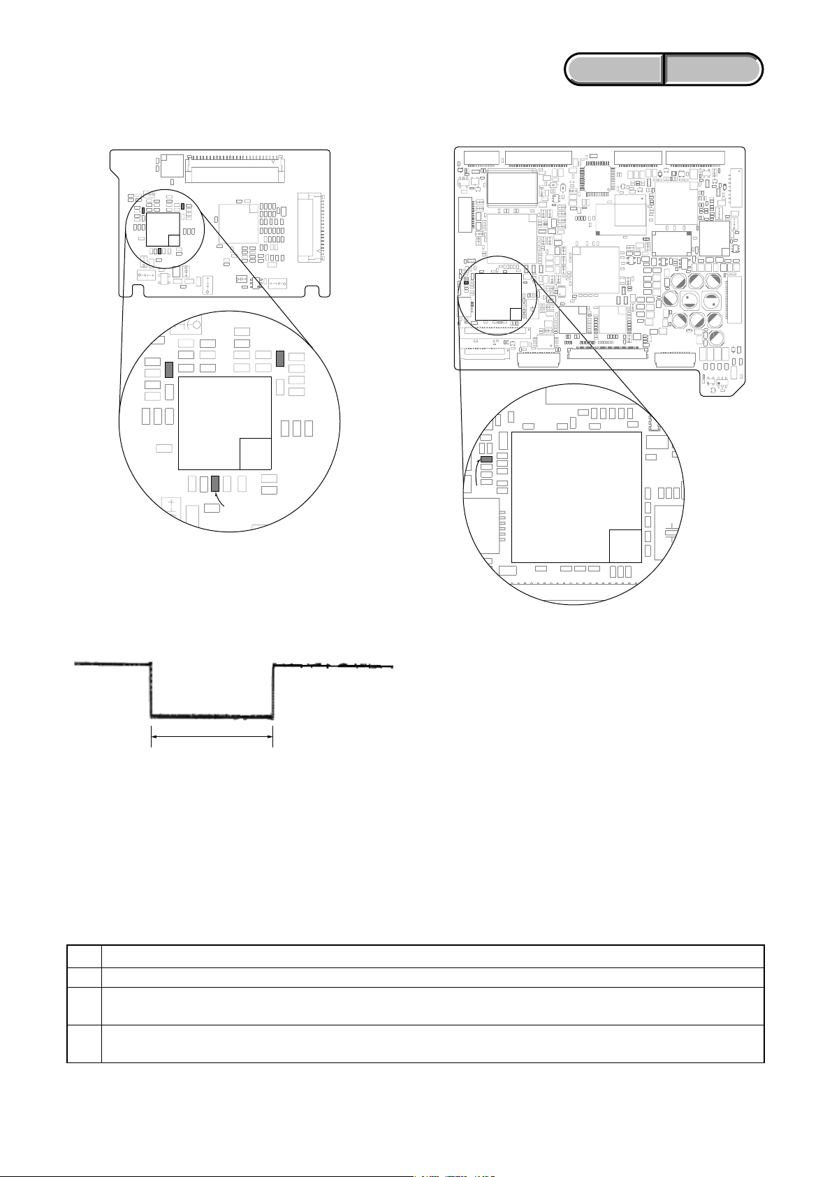
1-6. METHOD OF COPING WITH SHIFT LENS ERROR
R5792
IC5703
R5721
R5737
IC1801
R1823
IC1801
R1823
ENGLISH JAPANESE
ENGLISH JAPANESE
LD-229 BOARD (SIDE A)
VC-500 BOARD (SIDE A)
Fig. 1
Measurement points on the LD-229 board
Fig. 3
Measurement point on the VC-500 board
about 330 msec
Note: The length of low section will vary a little depending on the
conditions.
Fig. 2
Change in output voltage of R5792 on the LD-229 board
1-6-1. E : 62 : 02 [Abnormality of IC for Steadyshot] Occurred
Order Procedure
1Turn the power OFF.
While measuring with an oscilloscope the output voltage of R5792 in the periphery of IC5703 on the LD-229 board, turn the
2
power ON to check that the output voltage immediately after the power on change as shown in Fig. 2.
If the output voltage change as shown in Fig. 2, replace the lens block (Note). If it does not change as shown in Fig. 2, inspect
3
the camera control circuit (IC1801 of VC-500 board) periphery.
Note: When the lens block was replaced, execute a necessary adjustment items referring to “6. ADJUSTMENTS”.
HVR-HD1000J/HD1000U/HD1000N/HD1000E/HD1000P/HD1000C
After the adjustment, make sure with the STEADYSHOT turned ON that the steadyshot functions appropriately in the
handheld operation.
1-5
ENGLISH JAPANESE
ENGLISH JAPANESE
1-6-2. E : 62 : 10 [Shift Lens Initializing Failure] Occurred
Connect the adjustment remote commander (RM-95 or NEW LANC JIG) and perform the following process.
Order Page Address Data Procedure
10 0101
20 1007
F
3
(7F)
F
4
(7F)
F
5
(7F)
06 Read the data value and assume it as D
06
06 D
Change the data and check that it has been changed. If no value changes or if value is 00 or FF, inspect
the EEPROM (IC1802 of VC-500 board). If value changes, proceed to the order 5.
06 Press PAUSE (Write) button.
06.
F
6
(7F)
F
7
(7F)
F
8
(7F)
07 Read the data value and assume it as D
07
07 D
Change the data and check that it has been changed. If no value changes or if value is 00 or FF, inspect
the EEPROM (IC1802 of VC-500 board). If value changes, proceed to the order 8.
07 Press PAUSE (Write) button.
07.
90 1000
10 0 01 00
Perform “Hall Adjustment”. (Note 1)
11 If the lens does not move at all when adjusting it, proceed to the order 12. When the adjustment ends,
proceed to the order 16. (Note 1)
12 2 01 2D Press PAUSE (Write) button.
13 2 02
Read the data value. If value is not 01, inspect the EEPROM (IC1802 of VC-500 board). When value is
01, proceed to the order 14.
14 2 01 00 Press PAUSE (Write) button.
15 Turn the power OFF and ON again.
16 Check that no error occurs. If an error occurs, replace the lens block (Note 2).
Note 1: Perform adjustment by referring to “Hall Adjustment” in “6. ADJUSTMENTS”. After the adjustment, be sure to perform
“Angular Velocity Sensor Sensitivity Adjustment”.
Note 2: When the lens block was replaced, execute the necessary adjustment items referring to “6. ADJUSTMENTS”.
After the adjustment, make sure with the STEADYSHOT turned ON that the steadyshot functions appropriately in the
handheld operation.
HVR-HD1000J/HD1000U/HD1000N/HD1000E/HD1000P/HD1000C
1-6
ENGLISH JAPANESE
ENGLISH JAPANESE
1-6-3. E : 62 : 11 [Shift Lens Overheating (Pitch)] Occurred
Connect the adjustment remote commander (RM-95 or NEW LANC JIG) and perform the following process.
Order Page Address Data Procedure
10 0101
20 1006
B
3
(6B)
40 1007
D
5
(7D)
D
6
(7D)
D
7
(7D)
D
8
(7D)
D
9
(7D)
B2 01 Press PAUSE (Write) button.
46 F0 Press PAUSE (Write) button.
48 01 Press PAUSE (Write) button. (Note 1)
48 00 Press PAUSE (Write) button.
46 10 Press PAUSE (Write) button.
48 01 Press PAUSE (Write) button. (Note 1)
10
11 0 10 06
12
13 0 10 00
14 0 01 00
15
16
17
18 Turn the power OFF.
19
20
Note 1: Finish this operation within 10 seconds. If it is likely to take more than 10 seconds, set page: D (7D), address: 48, data:
Note 2: When the lens block was replaced, execute the necessary adjustment items referring to “6. ADJUSTMENTS”.
D
(7D)
B
(6B)
00, and then retry.
After the adjustment, make sure with the STEADYSHOT turned ON that the steadyshot functions appropriately in the
handheld operation.
48 00 Press PAUSE (Write) button.
B2 00 Press PAUSE (Write) button.
Check if the shift lens moves while setting the order 5 to 10. If the shift lens does not move, replace the
lens block (Note 2). When the shift lens moved, proceed to the order 16.
While setting the order 5 to 10, measure with an oscilloscope the output voltage of R5721 in the periphery
of IC5703 on the LD-229 board to check the output voltage varies.
If the output voltage does not vary, replace the lens block (Note 2). When the output voltage varied,
proceed to the order 18.
While measuring with an oscilloscope the output voltage of R5792 in the periphery of IC5703 on the
LD-229 board, turn the power ON to check that the output voltage immediately after the power on
change as shown in Fig. 2.
If the output voltage change as shown in Fig. 2, replace the lens block (Note 2). If it does not change as
shown in Fig. 2, inspect the camera control circuit (IC1801 of VC-500 board) periphery.
HVR-HD1000J/HD1000U/HD1000N/HD1000E/HD1000P/HD1000C
1-7
ENGLISH JAPANESE
ENGLISH JAPANESE
1-6-4. E : 62 : 12 [Shift Lens Overheating (Yaw)] Occurred
Connect the adjustment remote commander (RM-95 or NEW LANC JIG) and perform the following process.
Order Page Address Data Procedure
10 0101
20 1006
B
3
(6B)
40 1007
D
5
(7D)
D
6
(7D)
D
7
(7D)
D
8
(7D)
D
9
(7D)
B2 01 Press PAUSE (Write) button.
47 F0 Press PAUSE (Write) button.
49 01 Press PAUSE (Write) button. (Note 1)
49 00 Press PAUSE (Write) button.
47 10 Press PAUSE (Write) button.
49 01 Press PAUSE (Write) button. (Note 1)
10
11 0 10 06
12
13 0 10 00
14 0 01 00
15
16
17
18 Turn the power OFF.
19
20
Note 1: Finish this operation within 10 seconds. If it is likely to take more than 10 seconds, set page: D (7D), address: 49, data:
Note 2: When the lens block was replaced, execute the necessary adjustment items referring to “6. ADJUSTMENTS”.
D
(7D)
B
(6B)
00, and then retry.
After the adjustment, make sure with the STEADYSHOT turned ON that the steadyshot functions appropriately in the
handheld operation.
49 00 Press PAUSE (Write) button.
B2 00 Press PAUSE (Write) button.
Check if the shift lens moves while setting the order 5 to 10. If the shift lens does not move, replace the
lens block (Note 2). When the shift lens moved, proceed to the order 16.
While setting the order 5 to 10, measure with an oscilloscope the output voltage of R5737 in the periphery
of IC5703 on the LD-229 board to check the output voltage varies.
If the output voltage does not vary, replace the lens block (Note 2). When the output voltage varied,
proceed to the order 18.
While measuring with an oscilloscope the output voltage of R5792 in the periphery of IC5703 on the
LD-229 board, turn the power ON to check that the output voltage immediately after the power on
change as shown in Fig. 2.
If the output voltage change as shown in Fig. 2, replace the lens block (Note 2). If it does not change as
shown in Fig. 2, inspect the camera control circuit (IC1801 of VC-500 board) periphery.
1-6-5. E : 62 : 20 [Abnormality of Thermistor] Occurred
Order Procedure
1Turn the power ON.
Check that R1823 in the periphery of IC1801 on the VC-500 board is 0 Ω and energizes. If it is not energizes, replace the R1823.
2
When R1823 is 0 Ω and energizes, replace the lens block (Note).
Check that no error occurs, after replacing the lens block and performing the necessary adjustment. If an error occurs, inspect
3
the camera control circuit (IC1801 of VC-500 board) periphery.
Note: When the lens block was replaced, execute the necessary adjustment items referring to “6. ADJUSTMENTS”.
After the adjustment, make sure with the STEADYSHOT turned ON that the steadyshot functions appropriately in the
handheld operation.
HVR-HD1000J/HD1000U/HD1000N/HD1000E/HD1000P/HD1000C
1-8
Ver. 1.3 2008.12
ENGLISH JAPANESE
1. SERVICE NOTE
ENGLISH JAPANESE
1-1. 修理時の電源供給について
本機では,安定化電源(8.4Vdc)からバッテリ端子に電源を供給した場合,約10秒後にシャットオフし,動作しなくなります。
これを避けるため,下記の方法を用いてください。
方法:
ACアダプタ(AC-L100)を使用する。
1-2. イジェクトしない時のカセット取出し方法(強制イジェクト)
1 「2.DISASSEMBRY」を参照し,メカデッキブロックを外す。
2 カセコン組立を押さえながら,安定化電源より+4.5Vをローディングモータに加え,アンローディングさせる。
ローディングモータ
安定化電源(+4.5Vdc)
1-3. 強制電源ONモードの設定
調整リモコン(RM-95またはNEWLANCJIG)を使用して,電源を入れることが出来ます。
VTR操作は調整リモコンで行えます。
1-3-1. 強制カメラ電源ONモードの設定
1) ページ:0,アドレス:01にデータ:01をセット。
2) ページ:A,アドレス:10にデータ:01をセットしPAUSE(Write)ボタンを押す。
1-3-2. 強制VTR電源ONモードの設定
1) ページ:0,アドレス:01にデータ:01をセット。
2) ページ:A,アドレス:10にデータ:02をセットしPAUSE(Write)ボタンを押す。
1-3-3. 強制電源ONモードの解除
1) ページ:0,アドレス:01にデータ:01をセット。
2) ページ:A,アドレス:10にデータ:00をセットしPAUSE(Write)ボタンを押す。
3) ページ:0,アドレス:01にデータ:00をセット。
HVR-HD1000J/HD1000U/HD1000N/HD1000E/HD1000P/HD1000C
1-9
Ver. 1.3 2008.12
ENGLISH JAPANESE
ENGLISH JAPANESE
1-4. 使用サービス治具
CPC-15治具コネクタ(J-6082-564-A)およびLANC変換用I/F(J-6082-521-A)をUS-014基板CN8102に接続します。
CPC-15
(J-6082-564-A)
8
1
LANC変換用I/F
(J-6082-521-A)
VC-500 BOARD
(SIDE A)
CN1012
FP-786 Flexible
FLexible Flat Cable (FFC-107)
CN8003
CN8001 (SIDE B)
MS-379 BOARD
(SIDE A)
CN8101
8
1
CN8102
US-014 BOARD
(SIDE A)
1-5. 自己診断機能
1-5-1. 自己診断機能について
本機の動作に不具合が生じたとき,自己診断機能が働き,
ビューファインダまたはL C D 画面に,どう処置したらよい
か判断できる表示を行います。自己診断機能については取扱
説明書にも掲載されています。
ビューファインダまたはLCD画面
C : 3 1 : 1 1
3.2Hz点滅
1 1
詳細コード
「1-5 -3 .自己診断コード表」
を参照
対応者分類
C :お客さま自身で対応
H :販売店で対応
E :サービスエンジニア
で対応
3 1C
ブロック分類
対応方法の違いにより分類
例 31 ・・・テープを入れ直す
32 ・・・電源を入れ直す
1-5-2. 自己診断表示
本機の動作に不具合が生じたとき,ビューファインダまたは
LCD画面のカウンタ表示部分がアルファベットと数字の4桁
表示になり,3.2Hzで点滅します。この5文字の表示によっ
て対応者分類および不具合の生じたブロックの分類,不具合
の詳細コードを示します。
HVR-HD1000J/HD1000U/HD1000N/HD1000E/HD1000P/HD1000C
1-10

Ver. 1.3 2008.12
1-5-3. 自己診断コード表
自己診断コード
対
応
者
C
C
C
C
C
C
C
C
C
C
C
C
C
C
C
C
C
C
C
C
C
C
C
C
C
C
C
C
C
C
ブロック
機能
04
21
22
31
31
31
31
31
31
31
31
31
31
31
31
31
32
32
32
32
32
32
32
32
32
32
32
32
32
32
詳細
コード
00
00
00
10
11
20
21
22
23
30
31
40
41
42
43
44
10
11
20
21
22
23
30
31
40
41
42
43
44
60
症状/状態
標準でないバッテリを使用している
結露している
ビデオヘッドが汚れている
LOAD方向,ローディング所定時間
内終了せず
UNLOAD方向,ローディング所定時
間内終了せず
UNLOAD時,Tリール側テープ弛み
UNLOAD時,Sリール側テープ弛み
Tリール異常
Sリール異常
キャプスタン起動時FG異常
キャプスタン定常時FG異常
ドラム起動時FG異常
ドラム起動時PG異常
ドラム定常時FG異常
ドラム定常時PG異常
ドラム定常時位相異常
LOAD方向,ローディング所定時間
内終了せず
UNLOAD方向,ローディング所定時
間内終了せず
UNLOAD時,Tリール側テープ弛み
UNLOAD時,Sリール側テープ弛み
Tリール異常
Sリール異常
キャプスタン起動時FG異常
キャプスタン定常時FG異常
ドラム起動時FG異常
ドラム起動時PG異常
ドラム定常時FG異常
ドラム定常時PG異常
ドラム定常時位相異常
フォーカスが合いにくい
(フォーカスの初期化ができない)
ENGLISH JAPANESE
ENGLISH JAPANESE
対応/方法
インフォリチウムバッテリを使用する。
カセットを取り出して,約1時間してからもう一度入れ直す。
別売のクリーニングカセットできれいにする。
テープを入れ直し,再度操作し直す。
テープを入れ直し,再度操作し直す。
テープを入れ直し,再度操作し直す。
テープを入れ直し,再度操作し直す。
テープを入れ直し,再度操作し直す。
テープを入れ直し,再度操作し直す。
テープを入れ直し,再度操作し直す。
テープを入れ直し,再度操作し直す。
テープを入れ直し,再度操作し直す。
テープを入れ直し,再度操作し直す。
テープを入れ直し,再度操作し直す。
テープを入れ直し,再度操作し直す。
テープを入れ直し,再度操作し直す。
バッテリまたは電源ケーブルを外して付け直し,再度操作し直す。
バッテリまたは電源ケーブルを外して付け直し,再度操作し直す。
バッテリまたは電源ケーブルを外して付け直し,再度操作し直す。
バッテリまたは電源ケーブルを外して付け直し,再度操作し直す。
バッテリまたは電源ケーブルを外して付け直し,再度操作し直す。
バッテリまたは電源ケーブルを外して付け直し,再度操作し直す。
バッテリまたは電源ケーブルを外して付け直し,再度操作し直す。
バッテリまたは電源ケーブルを外して付け直し,再度操作し直す。
バッテリまたは電源ケーブルを外して付け直し,再度操作し直す。
バッテリまたは電源ケーブルを外して付け直し,再度操作し直す。
バッテリまたは電源ケーブルを外して付け直し,再度操作し直す。
バッテリまたは電源ケーブルを外して付け直し,再度操作し直す。
バッテリまたは電源ケーブルを外して付け直し,再度操作し直す。
バッテリまたは電源ケーブルを外して付け直し,再度操作し直す。
復帰しない場合,レンズブロックのフォーカスMR センサ(LD-229
基板CN5301qh,qkピン)を点検。問題がなければフォーカスモータ
ドライブ回路(LD-229基板IC5404)を点検。
HVR-HD1000J/HD1000U/HD1000N/HD1000E/HD1000P/HD1000C
1-11
Ver. 1.3 2008.12
自己診断コード
対
ブロック
応
機能
者
E
61
詳細
コード
10
症状/状態
ズーム動作の異常(ズームレンズの
初期化ができない)
ENGLISH JAPANESE
ENGLISH JAPANESE
対応/方法
ズームレバーを操作した時,ズーム動作をすればレンズブ
ロックのズームMRセンサ(LD-229基板CN5301w;,waピン)
を点検。ズーム動作をしなければズームモータドライブ回路
(LD-229基板IC5404)を点検。
E
E
E
E
E
E
E
E
E
61
62
62
62
62
62
62
62
62
11
00
01
02
03
10
11
12
20
(PITCH角速度センサ出力張り付き)
(YAW角速度センサ出力張り付き)
フォーカスレンズ初期化異常,ズー
ムレンズ初期化異常の同時発生
手振れ補正が効きにくい
手振れ補正が効きにくい
手振れ補正用ICの異常
手振れ補正用ICとマイクロコント
ローラーとの通信異常
シフトレンズ初期化異常
シフトレンズオーバーヒート
(PITCH)
シフトレンズオーバーヒート
(YAW)
サーミスタの異常
自己診断コードC:32:60とE:61:10の両方を点検。
PITCH角速度センサ(CM-077基板SE7202)周辺回路を点検。
YAW角速度センサ(CM-077基板SE7201)周辺回路を点検。
「1-6-1.E:62:02(手振れ補正用ICの異常)が出た場合」を参照。
手振れ補正回路(LD-229基板IC5703)を点検。
「1-6-2.E:62:10(シフトレンズ初期化異常)が出た場合」を参照。
「1-6-3.E:62:11(シフトレンズオーバーヒート(PITCH))が出
た場合」を参照。
「1-6-4.E:6 2:1 2(シフトレンズオーバーヒート(YAW))が出
た場合」を参照。
「1-6-5.E:62:20(サーミスタの異常)が出た場合」を参照。
HVR-HD1000J/HD1000U/HD1000N/HD1000E/HD1000P/HD1000C
1-12
R5792
IC5703
R5721
R5737
IC1801
R1823
IC1801
R1823
Ver. 1.3 2008.12
1-6. シフトレンズエラーの対処方法
ENGLISH JAPANESE
ENGLISH JAPANESE
LD-229 BOARD (SIDE A)
VC-500 BOARD (SIDE A)
図1.LD-229基板測定箇所
図3.VC-500基板測定箇所
約330msec
注: LOWの区間の長さは場合によって多少異なる。
図2.LD-229基板R5792の出力電圧の変化
1-6-1. E:62:02(手振れ補正用ICの異常)が出た場合
順序 作業内容
1 電源を切る。
LD-229基板IC5703の周辺にあるR5792の出力電圧をオシロスコープで測定しながら電源を入れる。電源投入直後の
2
出力電圧が図2の様に変化することを確認する。
出力電圧が図2の様に変化するときはレンズブロックを交換する(注)。図2の様に変化しないときはカメラコント
3
ロール回路(VC-500基板IC1801)周辺を点検する。
注: レンズブロックを交換した場合は,「6. ADJUSTMENTS」を参照して必要な調整項目を実施すること。調整後は手振
れ補正ONの状態にして,手持ち動作で手振れ補正が適切に動作していることを確認する。
HVR-HD1000J/HD1000U/HD1000N/HD1000E/HD1000P/HD1000C
1-13
Ver. 1.3 2008.12
1-6-2. E:62:10(シフトレンズ初期化異常)が出た場合
調整用リモコン(RM-95またはNEWLANCJIG)を接続し、次の手順を行う。
順序 ページ アドレスデータ 作業内容
10 0101
20 1007
F
3
(7F)
F
4
(7F)
F
5
(7F)
F
6
(7F)
F
7
(7F)
F
8
(7F)
06 データ値を読み取り,その値をD
06
06 D
データを変更し値が変わることを確認する。値が変化しない,もしくは値が00またはFFに
なっている場合はEEPROM(VC-500基板IC1802)を点検。値が変化する場合は順序5に進む。
06 PAUSE(Write)ボタンを押す。
07 データ値を読み取り,その値をD
07
07 D
データを変更し値が変わることを確認する。値が変化しない,もしくは値が00またはFFに
なっている場合はEEPROM(VC-500基板IC1802)を点検。値が変化する場合は順序8に進む。
07 PAUSE(Write)ボタンを押す。
90 1000
10 0 01 00
11
「HallAdjustment」を実行してください(注1)。調整をするときにレンズが全く動かない場合
は順序12に進む。調整が終わる場合は順序16に進む(注1)。
12 2 01 2D PAUSE(Write)ボタンを押す。
13 2 02
データ値を読み取り,値が01になっていない場合はEEPROM(VC-500基板IC1802)を点検。
値が01になってる場合は順序14に進む。
14 2 01 00 PAUSE(Write)ボタンを押す。
15 電源を切り,再び電源を入れる。
16
エラーが発生しないことを確認する。もしエラーが発生する場合はレンズブロックを交換
する(注2)。
06とする。
07とする。
ENGLISH JAPANESE
ENGLISH JAPANESE
注1:「6.ADJUSTMENTS」の「HallAdjustment」を参照して調整を実施すること。調整後は,「AngularVelocitySensor
SensitivityAdjustment」を必ず実施すること。
注2:レンズブロックを交換した場合は,「6.ADJUSTMENTS」を参照して必要な調整項目を実施すること。調整後は手振
れ補正ONの状態にして,手持ち動作で手振れ補正が適切に動作していることを確認する。
HVR-HD1000J/HD1000U/HD1000N/HD1000E/HD1000P/HD1000C
1-14
Ver. 1.3 2008.12
1-6-3. E:62:11(シフトレンズオーバーヒート(PITCH))が出た場合
調整用リモコン(RM-95またはNEWLANCJIG)を接続し、次の手順を行う。
順序 ページ アドレスデータ 作業内容
10 0101
20 1006
B
3
(6B)
40 1007
D
5
(7D)
D
6
(7D)
D
7
(7D)
D
8
(7D)
D
9
(7D)
D
10
(7D)
11 0 10 06
B
12
(6B)
13 0 10 00
14 0 01 00
15
16
17
18 電源を切る。
19
20
B2 01 PAUSE(Write)ボタンを押す。
46 F0 PAUSE(Write)ボタンを押す。
48 01 PAUSE(Write)ボタンを押す。(注1)
48 00 PAUSE(Write)ボタンを押す。
46 10 PAUSE(Write)ボタンを押す。
48 01 PAUSE(Write)ボタンを押す。(注1)
48 00 PAUSE(Write)ボタンを押す。
B2 00 PAUSE(Write)ボタンを押す。
順序5〜10を設定している間にシフトレンズが動いたか確認する。もしシフトレンズが動か
ない場合はレンズブロックを交換する(注2)。動く場合は順序16に進む。
LD-229基板IC5703の周辺にあるR5721の出力電圧をオシロスコープで測定しながら,順序5〜
10
を設定したときに出力電圧が変化することを確認する。
出力電圧が変化しないときはレンズブロックを交換する(注2)。変化するときは順序18に進む。
LD-229基板IC5703の周辺にあるR5792の出力電圧をオシロスコープで測定しながら電源を入
れる。電源投入直後の出力電圧が図2の様に変化することを確認する。
出力電圧が図2の様に変化するときはレンズブロックを交換する(注2)。図2の様に変化しな
いときはカメラコントロール回路(VC-500基板IC1801)周辺を点検する。
ENGLISH JAPANESE
ENGLISH JAPANESE
注1:この操作は10秒以内に終了してください。もし10秒以上経過しそうな場合は,ページ:D(7D),アドレス:48,デー
タ:00に設定しなおしてから再度実行してください。
注2:レンズブロックを交換した場合は,「6.ADJUSTMENTS」を参照して必要な調整項目を実施すること。調整後は手振
れ補正ONの状態にして,手持ち動作で手振れ補正が適切に動作していることを確認する。
HVR-HD1000J/HD1000U/HD1000N/HD1000E/HD1000P/HD1000C
1-15
Ver. 1.3 2008.12
ENGLISH JAPANESE
ENGLISH JAPANESE
1-6-4. E:62:12(シフトレンズオーバーヒート(YAW))が出た場合
調整用リモコン(RM-95またはNEWLANCJIG)を接続し、次の手順を行う。
順序 ページ アドレスデータ 作業内容
10 0101
20 1006
B
3
(6B)
40 1007
D
5
(7D)
D
6
(7D)
D
7
(7D)
D
8
(7D)
D
9
(7D)
D
10
(7D)
11 0 10 06
B
12
(6B)
13 0 10 00
14 0 01 00
15
16
17 出力電圧が変化しないときはレンズブロックを交換する(注2)。変化するときは順序18に進む。
18 電源を切る。
19
20
B2 01 PAUSE(Write)ボタンを押す。
47 F0 PAUSE(Write)ボタンを押す。
49 01 PAUSE(Write)ボタンを押す。(注1)
49 00 PAUSE(Write)ボタンを押す。
47 10 PAUSE(Write)ボタンを押す。
49 01 PAUSE(Write)ボタンを押す。(注1)
49 00 PAUSE(Write)ボタンを押す。
B2 00 PAUSE(Write)ボタンを押す。
順序5〜10を設定している間にシフトレンズが動いたか確認する。もしシフトレンズが動か
ない場合はレンズブロックを交換する(注2)。動く場合は順序16に進む。
LD-229基板IC5703の周辺にあるR5737の出力電圧をオシロスコープで測定しながら,順序5〜
10
を設定したときに出力電圧が変化することを確認する。
LD-229基板IC5703の周辺にあるR5792の出力電圧をオシロスコープで測定しながら電源を入
れる。電源投入直後の出力電圧が図2の様に変化することを確認する。
出力電圧が図2の様に変化するときはレンズブロックを交換する(注2)。図2の様に変化しな
いときはカメラコントロール回路(VC-500基板IC1801)周辺を点検する。
注1:この操作は10秒以内に終了してください。もし10秒以上経過しそうな場合は,ページ:D(7D),アドレス:49,デー
タ:00に設定しなおしてから再度実行してください。
注2:レンズブロックを交換した場合は,「6.ADJUSTMENTS」を参照して必要な調整項目を実施すること。調整後は手振
れ補正ONの状態にして,手持ち動作で手振れ補正が適切に動作していることを確認する。
1-6-5. E:62:20(サーミスタの異常)が出た場合
順序 作業内容
1 電源を入れる。
VC-500基板IC1801の周辺にあるR1823が0 Ωであり,かつ通電していることを確認する。通電していない場合は
2
R1823を交換する。R1823が0 Ωであり,かつ通電している場合は
レンズブロックを交換し必要な調整を行った後,エラーが発生しないことを確認する。もしエラーが発生する場
3
合はカメラコントロール回路(VC-500基板IC1801)周辺を点検する。
注: レンズブロックを交換した場合は,「6.ADJUSTMENTS」を参照して必要な調整項目を実施すること。調整後は手振れ
補正ONの状態にして,手持ち動作で手振れ補正が適切に動作していることを確認する。
HVR-HD1000J/HD1000U/HD1000N/HD1000E/HD1000P/HD1000C
レンズブロックを交換する(注)。
1-16E
2. DISASSEMBLY
Cut and remove the part of gilt
which comes off at the point.
(Be careful or some
pieces of gilt may be left inside)
NOTE FOR REPAIR
• Make sure that the flat cable and flexible board are not cracked of bent at the terminal.
Do not insert the cable insufficiently nor crookedly.
• When remove a connector, don’t pull at wire of connector. It is possible that a wire is snapped.
• When installing a connector, don’t press down at wire of connector.
It is possible that a wire is snapped.
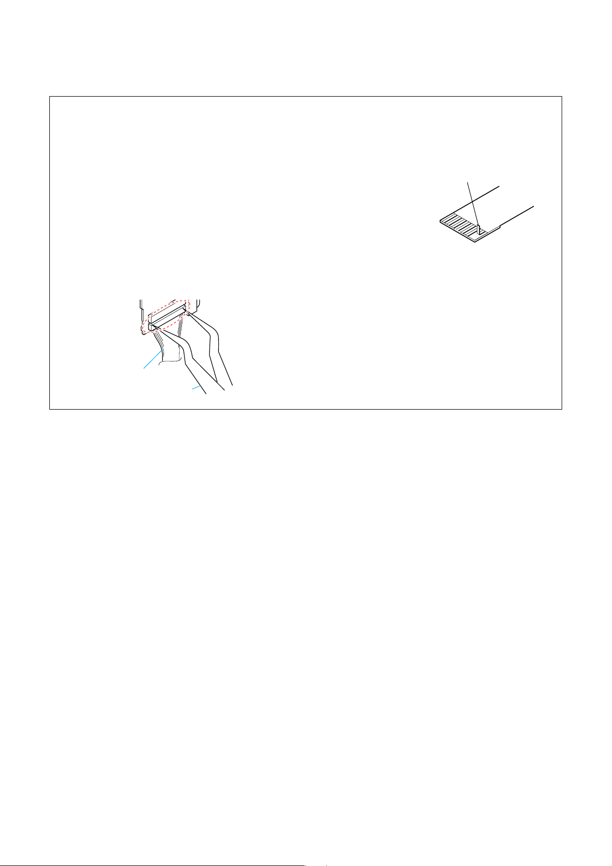
NOTE FOR DISCONNECTING THE HARNESS (HN-047)
When disconnecting the harness (HN-047), do not pull the
harness part but pull off the connector body with tweezers etc.
Harness (HN-047)
Tw eezers etc.
HVR-HD1000J/HD1000U/HD1000N/HD1000E/HD1000P/HD1000C
2-1
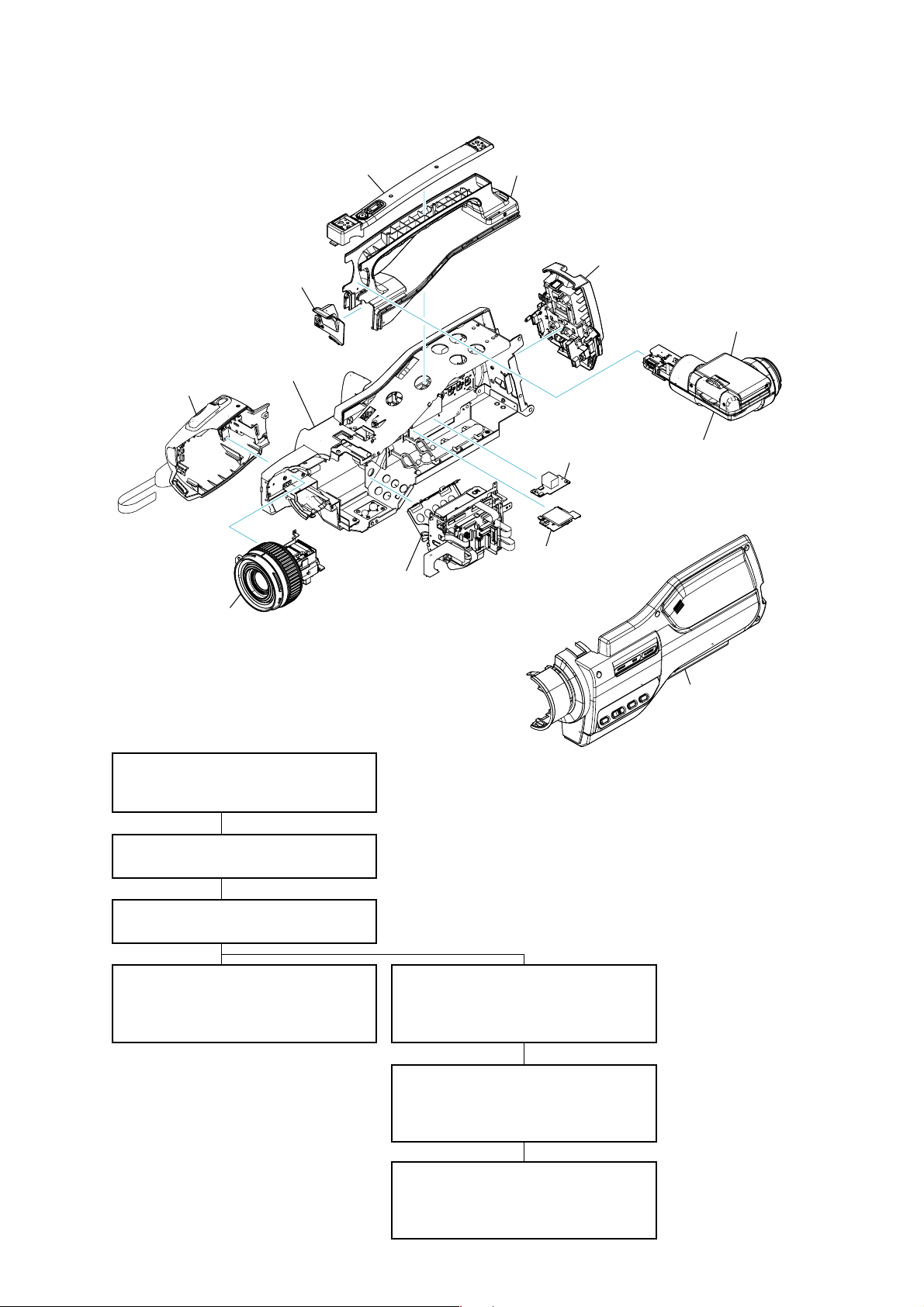
2-1. IDENTIFYING PARTS
Handle Cover
⋅ FP-793 Flexible Board
Handle Lower Cover
⋅ MC-188 Board
Cabinet (L)
⋅ JK-355 Board
Grip
⋅ NS-022 Board
⋅ JS-033 Board
Handle Assy
Battery Panel
⋅ BA-008 Board
⋅ DC-110 Board
⋅ HP-150 Board
LCD Panel
⋅ PD-342 Board
⋅ RE-038 Board
Lens
⋅ CM-077 Board
⋅ EC-001 Board
⋅ LD-229 Board
- DISASSEMBLY FLOW -
2-2-1. OVERALL SECTION-1
⋅ Grip
⋅ Cabinet (R)
2-2-2. OVERALL SECTION-2
⋅ Lens
G Block
⋅ FP-785 Flexible Board
⋅ FP-786 Flexible Board
⋅ FP-787 Flexible Board
⋅ FP-788 Flexible Board
⋅ FP-789 Flexible Board
⋅ FP-867 Flexible Board
⋅ IF-155 Board
⋅ VC-500 Board
⋅ Mechanism Deck
US-014 Board
MS-379 Board
View Finder
⋅ BL-015 Board
⋅ BH-001 Board
⋅ FP-784 Flexible Board
⋅ HI-078 Board
Cabinet (R)
⋅ MO-027 Board
⋅ SP-048 Board
2-2-3. HANDLE (TALLY) SECTION
⋅ View Finder
2-2-4. VIEW FINDER SECTION
⋅ LCD Panel
⋅ VF Hinge
⋅ EVF Panel
HVR-HD1000J/HD1000U/HD1000N/HD1000E/HD1000P/HD1000C
2-2-5. HANDLE (COVER) SECTION
⋅ Handle Cover
⋅ Handle Lower Cover
⋅ Handle Assy
2-2-6. OVERALL SECTION-3
⋅ Battery Panel
⋅ G Block
⋅ Cabinet (L)
2-2-7. G BLOCK SECTION
⋅ IF-155 Board
⋅ VC-500 Board
⋅ Mechanism Deck
2-2
HELP
EXPLODED VIEW
HELP
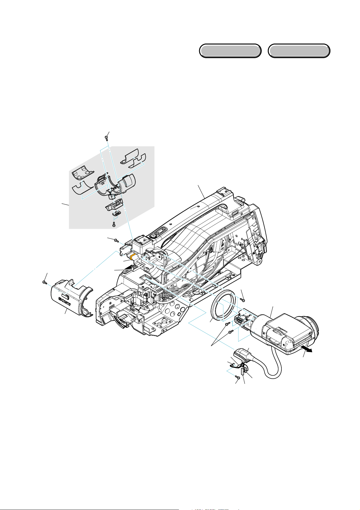
2-2. DISASSEMBLY
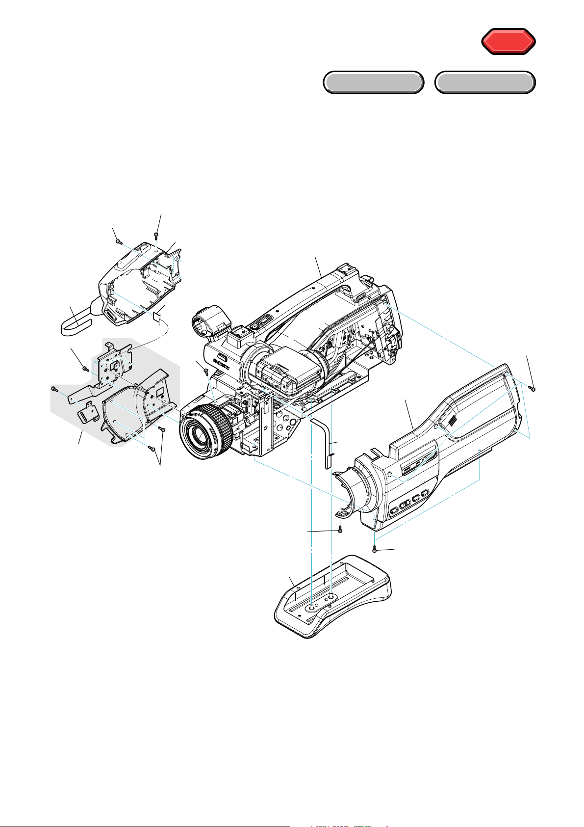
2-2-1. OVERALL SECTION-1
Follow the disassembly in the numerical order given.
1 Grip (1-1 to 1-7)
2 Cabinet (R) (2-1 to 2-6)
1-3 (#100)
1-4 (#100)
1 Grip
1-1
1-6 (#103)
1-5
2-2
(#100)
HARDWARE LIST
Overall Section-2
(See Page 2-4)
2-5
(#104)
1-7
2 Cabinet (R)
2-6
1-2 (#37)
2-3 (#100)
2-4 (#49)
2-1
HVR-HD1000J/HD1000U/HD1000N/HD1000E/HD1000P/HD1000C
2-3
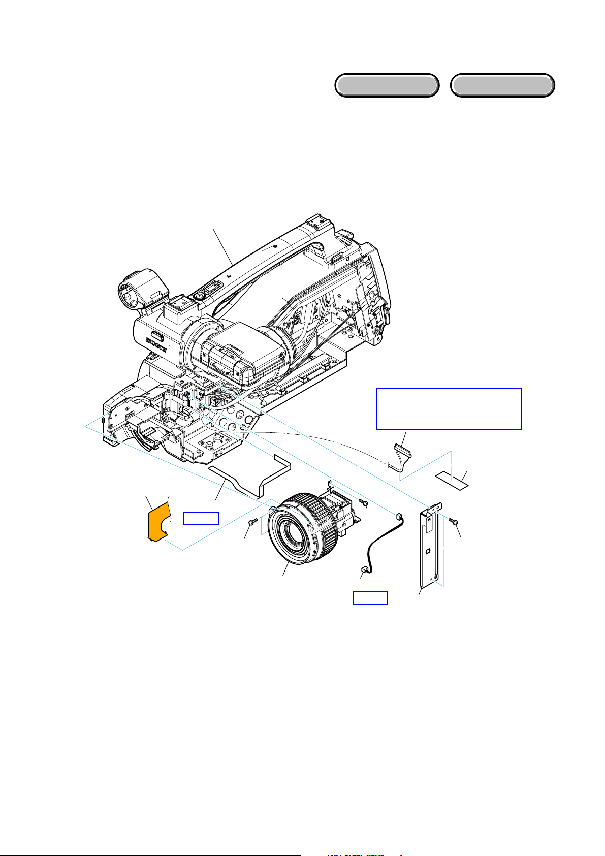
2-2-2. OVERALL SECTION-2
EXPLODED VIEW
Follow the disassembly in the numerical order given.
1 Lens (1-1 to 1-9)
Handle (Tally) Section
(See Page 2-5)
HARDWARE LIST
1-9
1-4
HELP 1
1-7 (#49)
1 Lens
1-8
Note: Refer to page 2-1 “Note
for disconnecting the
harness (HN-047)”.
1-6
(#49)
1-3
HELP 1
1-2
1-5
1-1 (#49)
HVR-HD1000J/HD1000U/HD1000N/HD1000E/HD1000P/HD1000C
2-4
2-2-3. HANDLE (TALLY) SECTION
EXPLODED VIEW
Follow the disassembly in the numerical order given.
1 View Finder (1-1 to 1-17)
1-7 (#102)
1-8
HARDWARE LIST
Handle (Cover) Section
(See Page 2-7)
1-12 (#49)
1-13
1-11 (#49)
1-14
1-15
1-17
1-16 (#49)
1-10 (#23)
1-5
1-2
1-1 (#37)
1 View Finder
(See Page 2-6)
1-6
1-9 (Slide)
1-4
1-3
HVR-HD1000J/HD1000U/HD1000N/HD1000E/HD1000P/HD1000C
2-5
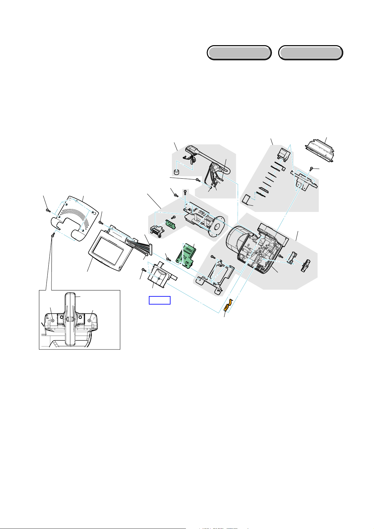
2-2-4. VIEW FINDER SECTION
EXPLODED VIEW
Follow the disassembly in the numerical order given.
1 LCD Panel (1-1 to 1-20)
2 VF Hinge (2-1 to 2-2)
3 EVF Panel (3-1 to 3-3)
HARDWARE LIST
1-4 (#37)
1-3
(#49)
1-5
2 VF Hinge
1-6 (#37)
1 LCD Panel
1-1 (Rotate)
1-2 (#49)
1-18
1-19
1-7
(#37)
1-10
(#105)
2-2 (#37)
1-17
(#105)
1-8
HELP 2
1-15
1-11
1-20
1-14
1-12
1-13
3 EVF Panel
1-16
2-1
(Rotate)
3-1
3-2
(#37)
3-3
1-9
HVR-HD1000J/HD1000U/HD1000N/HD1000E/HD1000P/HD1000C
2-6
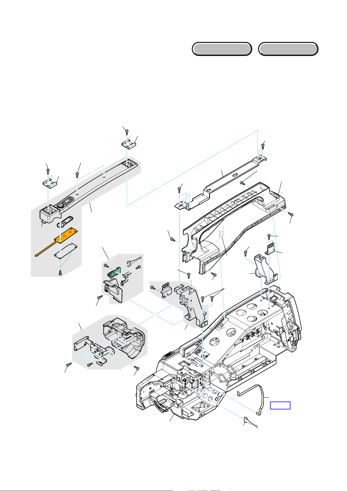
EXPLODED VIEW
2-2-5. HANDLE (COVER) SECTION
Follow the disassembly in the numerical order given.
1 Handle Cover (1-1 to 1-6)
2 Handle Lower Cover (2-1 to 2-6)
3 Handle Assy (3-1 to 3-15)
1-3 (#107)
HARDWARE LIST
1-4
3-2 (#49)
1-1 (#107)
1-6
(Claw)
1-2
1-5 (#37)
2-6 (#49)
2-3
1 Handle Cover
2 Handle Lower
Cover
3-4 (#49)
3-9 (#49)
3-1 (#49)
3-6 (#49)
3-3
3-8
(Claw)
3-10 (#49)
3-15
3-5 (#49)
3 Handle Assy
3-14
(#100)
3-12 (#100)
3-7 (#49)
3-13
2-1 (#106)
2-2 (#106)
Overall Section-3
(See Page 2-8)
HVR-HD1000J/HD1000U/HD1000N/HD1000E/HD1000P/HD1000C
3-11
2-4
HELP 3
2-5
2-7
 Loading...