

Sony HCD-RV222D, HCD-RV222DL, HCD-RV333D, HCD-RV555D, HCD-RV333DL Service Manual
HCD-RV222D/RV222DL/RV333D/
RV333DL/RV555D
SERVICE MANUAL
Ver. 1.3 2011.01
• HCD-RV222D/RV222DL/RV333D/RV333DL/
RV555D are the tuner, deck, DVD and amplifi er
section in MHC-RV222D/RV222DL/RV333D/
RV333DL/RV555D.
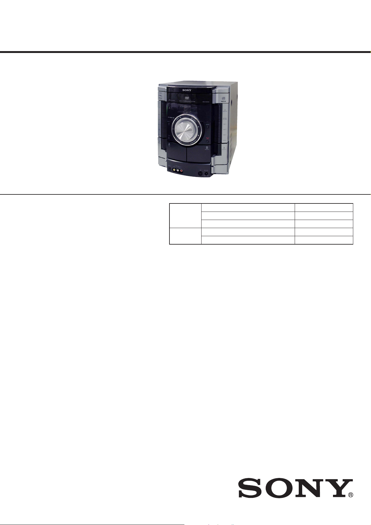
Photo: HCD-RV555D
DVD
Section
Tape Deck
Section
E Model
HCD-RV222D/RV333D/RV555D
Russian Model
HCD-RV222D/RV222DL/RV333D/RV333DL
Model Name Using Similar Mechanism New
DVD Mechanism Type CDM74HFV-DVBU101
Optical Pick-up Name KHM-313CAB
Model Name Using Similar Mechanism New
Tape Transport Mechanism Type CWP42FF603
Amplifi er section
The following measured at AC 230 V,
50/60 Hz (Russian model)
The following measured at AC 240 V,
50/60 Hz (South African model)
The following measured at AC 127, 240 V,
50/60 Hz (Saudi Arabian model)
The following measured at AC 120, 220,
240 V, 50/60 Hz (Other models)
MHC-RV555D (models with Karaoke
function only)
Power output (rated):
85 W + 85 W (6 Ω at 1 kHz, 1% THD,
at LINK MODE)
RMS output power (reference)
Front speaker:
130 W + 130 W (per channel at 8 Ω,
1 kHz, 10% THD)
Satellite speaker:
50 W + 50 W (per channel at 24 Ω,
1 kHz, 10% THD)
SPECIFICATIONS
MHC-RV555D (models without
Karaoke function only)
Power output (rated):
105 W + 105 W (6 Ω at 1 kHz, 1%
THD, at LINK MODE)
RMS output power (reference)
Front speaker:
150 W + 150 W (per channel at 8 Ω,
1 kHz, 10% THD)
Satellite speaker:
60 W + 60 W (per channel at 24 Ω,
1 kHz, 10% THD)
MHC-RV333D/RV333DL
(Russian and African models only)
Power output (rated):
70 W + 70 W (6 Ω at 1 kHz, 1%
THD)
RMS output power (reference)
Front speaker:
120 W + 120 W (per channel at 6 Ω,
1 kHz, 10% THD)
Subwoofer:
120 W (at 6 Ω, 80 Hz, 10% THD)
MHC-RV333D (Saudi Arabian and
South African models only)
Power output (rated):
55 W + 55 W (6 Ω at 1 kHz, 1%
THD)
RMS output power (reference)
Front speaker:
100 W + 100 W (per channel at 6 Ω,
1 kHz, 10% THD)
Subwoofer:
100 W (at 6 Ω, 80 Hz, 10% THD)
MHC-RV222D/RV222DL
Power output (rated):
65 W + 65 W (6 Ω at 1 kHz, 1%
THD)
RMS output power (reference):
120 W+ 120 W (per channel at 6 Ω,
1 kHz, 10% THD)
– Continued on next page –
9-889-516-04
2011A04-1
2011.01
©
DVD DECK RECEIVER
Sony Corporation
Published by Sony Techno Create Corporation

HCD-RV222D/RV222DL/RV333D/RV333DL/RV555D
Ver. 1.3
Inputs
VIDEO INPUT VIDEO (phono jack):
1 Vp-p, 75 ohms
VIDEO (SAT) INPUT AUDIO L/R (phono
jacks):
voltage 250 (450) mV, impedance
47 kilohms
MIC (phone jacks) (EA, PH, RU, SAF, SP
model only):
sensitivity 2 mV, impedance
10 kilohms
Outputs
VIDEO OUT (phono jack):
max. output level 1 Vp-p, unbalanced,
Sync negative, load impedance
75 ohms
DVD DIGITAL OUT (Square optical
connector jack, rear panel):
Wavelength 650 nm
PHONES (stereo mini jack):
accepts headphones of 8 ohms or
more
FRONT SPEAKER:
MHC-RV555D:
Use only the supplied speaker SS-RV555D.
MHC-RV333D/RV333DL:
Use only the supplied speaker SS-RV222D.
MHC-RV222D/RV222DL:
Use only the supplied speaker SS-RV222D.
SATELLITE SPEAKER (MHC-RV555D only):
Use only the supplied speaker SS-RSX555D.
SUBWOOFER (MHC-RV333D/RV333DL only):
Use only the supplied subwoofer
SS-WG333D.
Disc player section
System:
Compact disc and digital audio and
video system
Laser Diode Properties
Emission duration: Continuous
Laser Output*: Less than 44.6μW
* This output is the value measurement
at a distance of 200mm from the
objective lens surface on the Optical
Pick-up Block with 7mm aperture.
Frequency response
DVD (PCM 48 kHz): 2 Hz ‒ 22 kHz
(±1 dB)
CD: 2 Hz ‒ 20 kHz (±0.5 dB)
Video color system format
Russian model: PAL
Other models: NTSC and PAL
Tuner section
FM stereo, FM/AM superheterodyne tuner
Antenna:
FM lead antenna
AM loop antenna
FM tuner section:
Tuning range:
87.5 ‒ 108.0 MHz (50 kHz step)
Intermediate frequency: 225 kHz
AM tuner section:
Tuning range:
Russian and Saudi Arabian models:
531 ‒ 1,602 kHz (9 kHz step)
Other models:
531 ‒ 1,602 kHz (9 kHz)
530 ‒ 1,610 kHz (10 kHz)
Intermediate frequency: 53 kHz
General
Power requirements
Russian model:
AC 230 V, 50/60 Hz
South African model:
AC 220 ‒ 240 V, 50/60 Hz
Saudi Arabian model:
AC 120 ‒ 127, 220 ‒ 240 V,
50/60 Hz, adjustable with voltage selector
Other models:
AC 120, 220, 230 ‒ 240 V, 50/60 Hz,
adjustable with voltage selector
Power consumption
MHC-RV555D (models with Karaoke
function only): 185 W
MHC-RV555D (models without Karaoke
function only): 215 W
MHC-RV333D/RV333DL (Russian model only):
200 W (0.5 W at the Power Saving Mode)
MHC-RV333D (African model only):
210 W
MHC-RV333D (South African model
only): 175 W
MHC-RV333D (Saudi Arabian model
only): 180 W
MHC-RV222D/RV222DL: 160 W
(Russian model: 0.5 W at the Power
Saving Mode)
Dimensions (w/h/d) (excl. speakers)
Approx. 280 × 325 × 375 mm
Mass (excl. speakers)
MHC-RV555D: Approx. 9.8 kg
MHC-RV333D/RV333DL: Approx. 9.3 kg
MHC-RV222D/RV222DL: Approx. 8.5 kg
Tape deck section
Recording system:
4-track 2-channel, stereo
2
Design and specifi cations are subject to
change without notice.
• Abbreviation
EA : Saudi Arabia model
PH : Philippines model
RU : Russian model
SAF : South African model
SP : Singapore model
SAFETY-RELATED COMPONENT WARNING!
COMPONENTS IDENTIFIED BY MARK 0 OR DOTTED LINE
WITH MARK 0 ON THE SCHEMATIC DIAGRAMS AND IN
THE PARTS LIST ARE CRITICAL TO SAFE OPERATION.
REPLACE THESE COMPONENTS WITH SONY PARTS
WHOSE PART NUMBERS APPEAR AS SHOWN IN THIS
MANUAL OR IN SUPPLEMENTS PUBLISHED BY SONY.
HCD-RV222D/RV222DL/RV333D/RV333DL/RV555D
NOTES ON CHIP COMPONENT REPLACEMENT
• Never reuse a disconnected chip component.
• Notice that the minus side of a tantalum capacitor may be damaged by heat.
FLEXIBLE CIRCUIT BOARD REPAIRING
• Keep the temperature of soldering iron around 270 °C during
repairing.
• Do not touch the soldering iron on the same conductor of the
circuit board (within 3 times).
• Be careful not to apply force on the conductor when soldering
or unsoldering.
UNLEADED SOLDER
Boards requiring use of unleaded solder are printed with the leadfree mark (LF) indicating the solder contains no lead.
(Caution: Some printed circuit boards may not come printed with
the lead free mark due to their particular size)
: LEAD FREE MARK
Unleaded solder has the following characteristics.
• Unleaded solder melts at a temperature about 40 °C higher
than ordinary solder.
Ordinary soldering irons can be used but the iron tip has to be
applied to the solder joint for a slightly longer time.
Soldering irons using a temperature regulator should be set to
about 350 °C.
Caution: The printed pattern (copper foil) may peel away if
the heated tip is applied for too long, so be careful!
• Strong viscosity
Unleaded solder is more viscous (sticky, less prone to fl ow)
than ordinary solder so use caution not to let solder bridges
occur such as on IC pins, etc.
• Usable with ordinary solder
It is best to use only unleaded solder but unleaded solder may
also be added to ordinary solder.
NOTES ON LASER DIODE EMISSION CHECK
The laser beam on this model is concentrated so as to be focused
on the disc refl ective surface by the objective lens in the optical
pickup block. Therefore, when checking the laser diode emission,
observe from more than 30 cm away from the objective lens.
Laser component in this product is capable of emitting radiation
exceeding the limit for Class 1.
This appliance is classifi ed as
a CLASS 1 LASER product.
This marking is located on the
rear or bottom exterior.
CAUTION
Use of controls or adjustments or performance of procedures
other than those specifi ed herein may result in hazardous radia-
tion exposure.
NOTES ON HANDLING THE OPTICAL PICK-UP
BLOCK OR BASE UNIT
The laser diode in the optical pick-up block may suffer electrostatic break-down because of the potential difference generated by
the charged electrostatic load, etc. on clothing and the human body.
During repair, pay attention to electrostatic break-down and also
use the procedure in the printed matter which is included in the
repair parts.
The fl exible board is easily damaged and should be handled with
care.
3
HCD-RV222D/RV222DL/RV333D/RV333DL/RV555D
Ver. 1.3
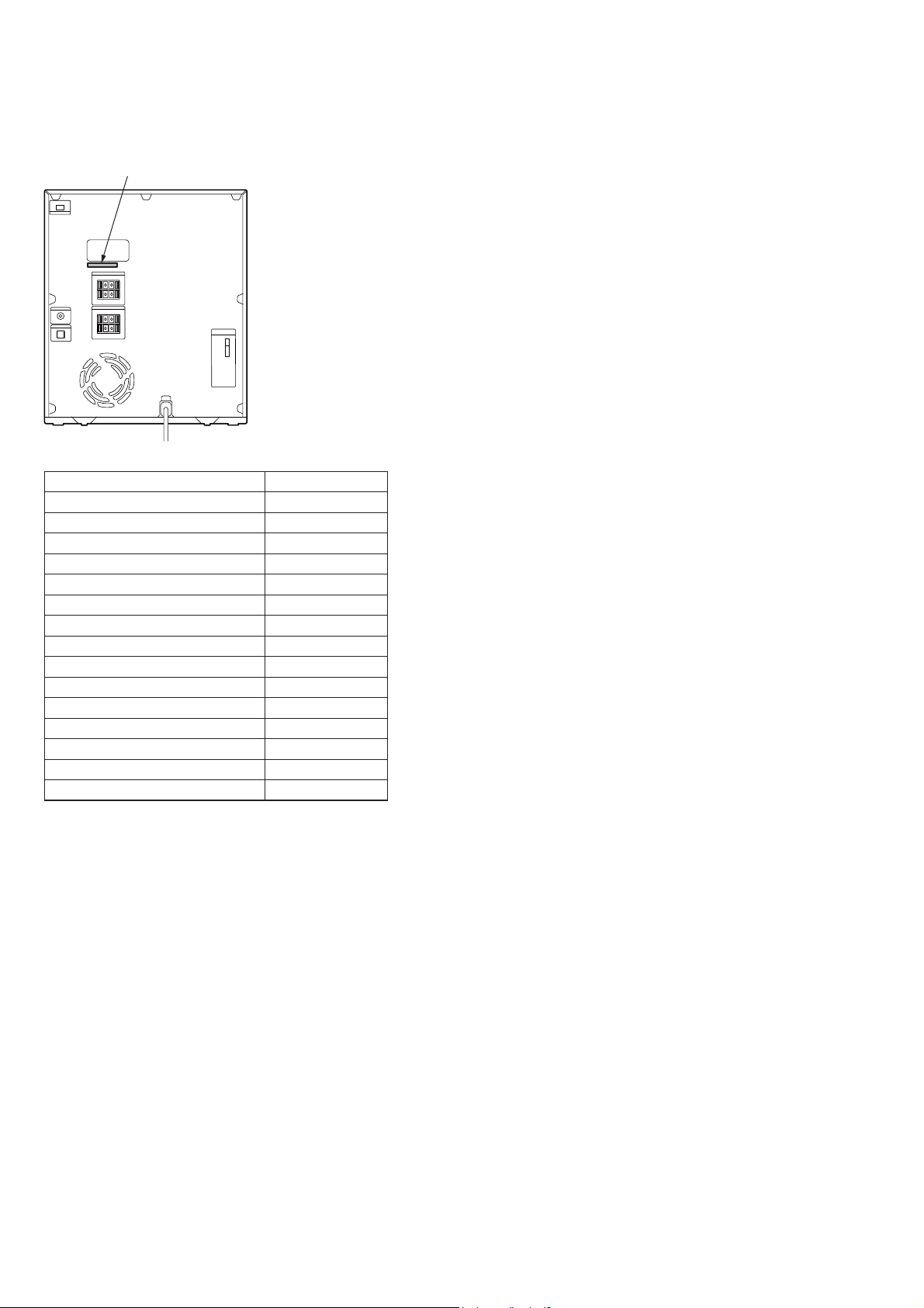
MODEL IDENTIFICATION
– Back Panel or Model Number Label –
Parts No.
Model Part No.
RV222D: E3, E15 model
RV222D: E4 model
RV222D: PH model
RV222D: SP model
RV222D: RU model
RV222D: EA model
RV555D: E3, E15 model
RV555D: E4 model
RV555D: SP model
RV333D: SAF model
RV333D: RU model
RV333D: EA model
RV333D: E4 model
RV222DL: RU model
RV333DL: RU model
4-128-091-0[]
4-128-091-1[]
4-128-091-2[]
4-128-091-3[]
4-128-091-5[]
4-128-091-6[]
4-131-194-0[]
4-131-194-1[]
4-131-194-2[]
4-131-195-0[]
4-131-195-1[]
4-131-195-2[]
4-131-195-3[]
4-278-386-0[]
4-278-387-0[]
• Abbreviation
E3 : 240V AC area in E model
E4 : 220 – 240V AC area in E model
E15 : Iranian model
EA : Saudi Arabia model
PH : Philippines model
RU : Russian model
SAF : South African model
SP : Singapore model
4

HCD-RV222D/RV222DL/RV333D/RV333DL/RV555D
Ver. 1.3
TABLE OF CONTENTS
1. SERVICING NOTES ............................................. 6
2. DISASSEMBLY
2-1. Case ................................................................................. 9
2-2. VOL-LED Board ............................................................ 9
2-3. Tuner Assy ...................................................................... 10
2-4. Loading Panel ................................................................. 10
2-5. DVD Block ..................................................................... 11
2-6. Front Panel Section ......................................................... 11
2-7. Back Panel Section ......................................................... 12
2-8. MAIN Board ................................................................... 12
2-9. 2CH-AMP Board (RV222D/RV222DL/RV555D),
3CH-AMP Board (RV333D/RV333DL) ......................... 13
2-10. Tape Mechanism Block................................................... 13
2-11. JACK-MIC AMP Board ................................................. 14
2-12. Lid (TC-L), Lid (TC-R) .................................................. 14
2-13. TC AMP Board ............................................................... 15
2-14. PANEL Board ................................................................. 15
2-15. KEY-RIGHT Board ........................................................ 16
2-16. KEY-LEFT Board ........................................................... 16
2-17. DMB19 Board ................................................................. 17
2-18. Base Unit ......................................................................... 17
2-19. Optical Pick-up ............................................................... 18
2-20. DRIVER Board, SW Board ............................................ 18
2-21. SENSOR Board .............................................................. 19
2-22. MOTOR (TB) Board....................................................... 19
2-23. MOTOR (LD) Board ...................................................... 20
3. TEST MODE ............................................................ 21
4. ELECTRICAL ADJUSTMENTS ........................ 26
5. DIAGRAMS
5-1. Block Diagram –RF Section– ......................................... 28
5-2. Block Diagram –DVD Out Section– .............................. 29
5-3. Block Diagram –Audio Section– .................................... 30
5-4. Block Diagram –Tape Section– ...................................... 31
5-5. Block Diagram –AMP Section– ..................................... 32
5-6. Block Diagram –Power Section– .................................... 33
5-7. Printed Wiring Boards –Driver Section– ........................ 35
5-8. Schematic Diagram –Driver Section– ............................ 36
5-9. Printed Wiring Board –DMB19 Section (1/2)– .............. 37
5-10. Printed Wiring Board –DMB19 Section (2/2)– .............. 38
5-11. Schematic Diagram –DMB19 Section (1/4)– ................. 39
5-12. Schematic Diagram –DMB19 Section (2/4)– ................. 40
5-13. Schematic Diagram –DMB19 Section (3/4)– ................. 41
5-14. Schematic Diagram –DMB19 Section (4/4)– ................. 42
5-15. Printed Wiring Boards –REG/Tuner Section– ................ 43
5-16. Schematic Diagram –REG Section– ............................... 44
5-17. Schematic Diagram –Tuner Section– ............................. 45
5-18. Printed Wiring Board –Main Section– ............................ 46
5-19. Schematic Diagram –Main Section (1/3)– ...................... 47
5-20. Schematic Diagram –Main Section (2/3)– ...................... 48
5-21. Schematic Diagram –Main Section (3/3)– ...................... 49
5-22. Printed Wiring Board –Jack-MIC AMP Section– ........... 50
5-23. Schematic Diagram –Jack-MIC AMP Section–.............. 51
5-24. Printed Wiring Board –TC AMP Section– ...................... 52
5-25. Schematic Diagram –TC AMP Section– ........................ 53
5-26. Printed Wiring Boards –Panel Section– .......................... 54
5-27. Printed Wiring Boards –Key-Left/Key-Right Section– ... 55
5-28. Schematic Diagram –Panel Section– .............................. 56
5-29. Printed Wiring Board
–2CH-AMP Section (RV222D/RV222DL/RV555D)– ... 57
5-30. Schematic Diagram
–2CH-AMP Section (RV222D/RV222DL/RV555D)– ... 58
5-31. Printed Wiring Board
–3CH-AMP Section (RV333D/RV333DL)– ................... 59
5-32. Schematic Diagram
–3CH-AMP Section (RV333D/RV333DL)– ................... 60
5-33. Printed Wiring Board
–Power Section (RV222D/RV222DL)– .......................... 61
5-34. Schematic Diagram
–Power Section (RV222D/RV222DL)– .......................... 62
5-35. Printed Wiring Board
–Power Section (RV333D/RV333DL/RV555D)–........... 63
5-36. Schematic Diagram
–Power Section (RV333D/RV333DL/RV555D)–........... 64
6. EXPLODED VIEWS
6-1. Overall Section ............................................................... 74
6-2. Front Panel Section-1 ...................................................... 75
6-3. Front Panel Section-2 ...................................................... 76
6-4. Chassis Section ............................................................... 77
6-5. DVD Section ................................................................... 78
6-6. DVD Mechanism Deck Section-1 .................................. 79
6-7. DVD Mechanism Deck Section-2 .................................. 80
7. ELECTRICAL PARTS LIST .............................. 81
5
HCD-RV222D/RV222DL/RV333D/RV333DL/RV555D
SECTION 1
SERVICING NOTES
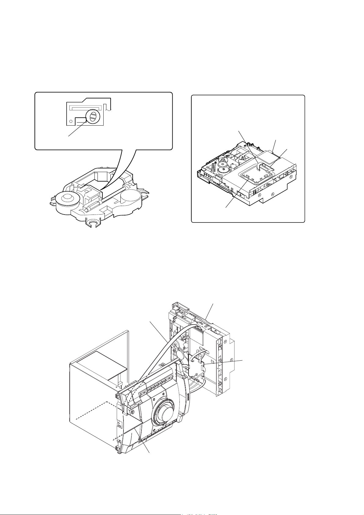
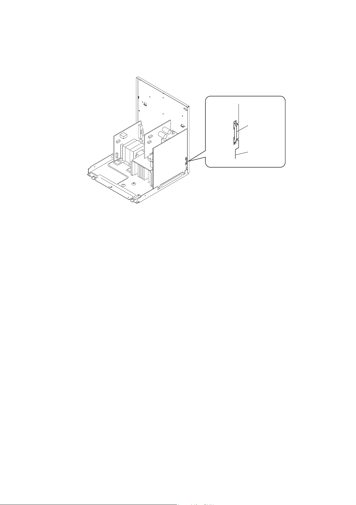
Notes on Disconnecting Between the OP Section (DVBU101) and the DMB19 Board
Note: When disconnecting between the OP section (DVBU101) and the DMB19 board, be sure to make a solder bridge for electrostatic prevention as il-
lustrated in the fi gure (before disconnection).
On the contrary, when installing the OP section, never remove the solder bride until the OP section and the DMB19 board are connected.
Be sure to remove the solder bridge after the OP section and the DMB19 board have been connected.
Lead the flat cable through the hole in the
sub chassis and connect it to the connector
CN101 on the DMB19 board.
flat cable
Perform solder bridging to prevent damage by electrostatic
discharge when handling the BU as a single unit.
sub chassis
hole
Service Position for the DVD Mechanism Deck Section
Refer to the fi gure given below when disassembling the DVD mechanism deck section.
Use the extension cable J-2501-077-A (1.25mm/13P/300L) as illustrated below.
DVD mechanism deck section
J-2501-077-A
DMB19 board
DMB19 board
MAIN board
6
HCD-RV222D/RV222DL/RV333D/RV333DL/RV555D
Arranging the Wire from the Fan
Arrange the wire as illustrated below in order to prevent contact with the heat sink.
wire
MAIN board
7
HCD-RV222D/RV222DL/RV333D/RV333DL/RV555D
Ver. 1.3
SECTION 2
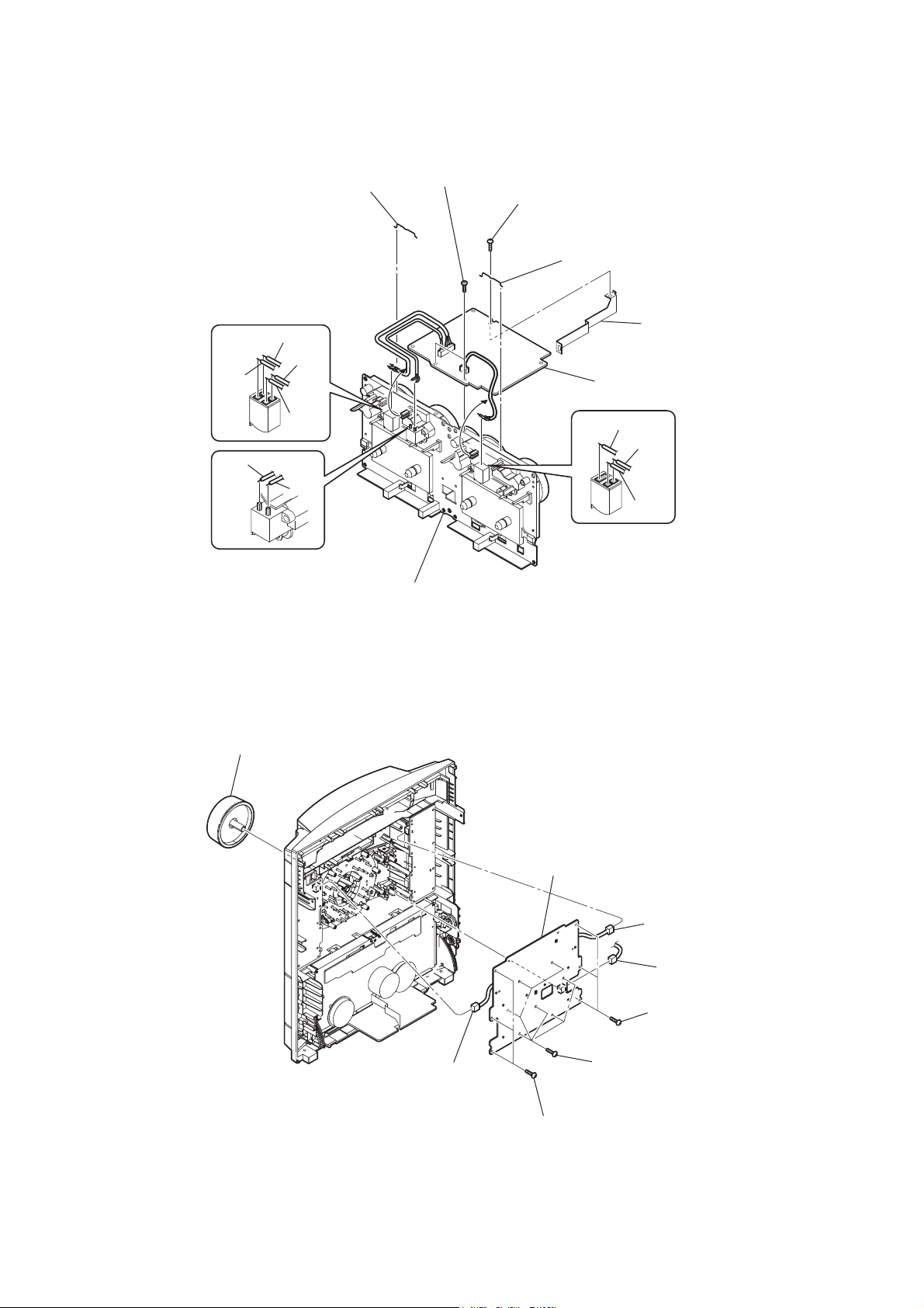
DISASSEMBLY
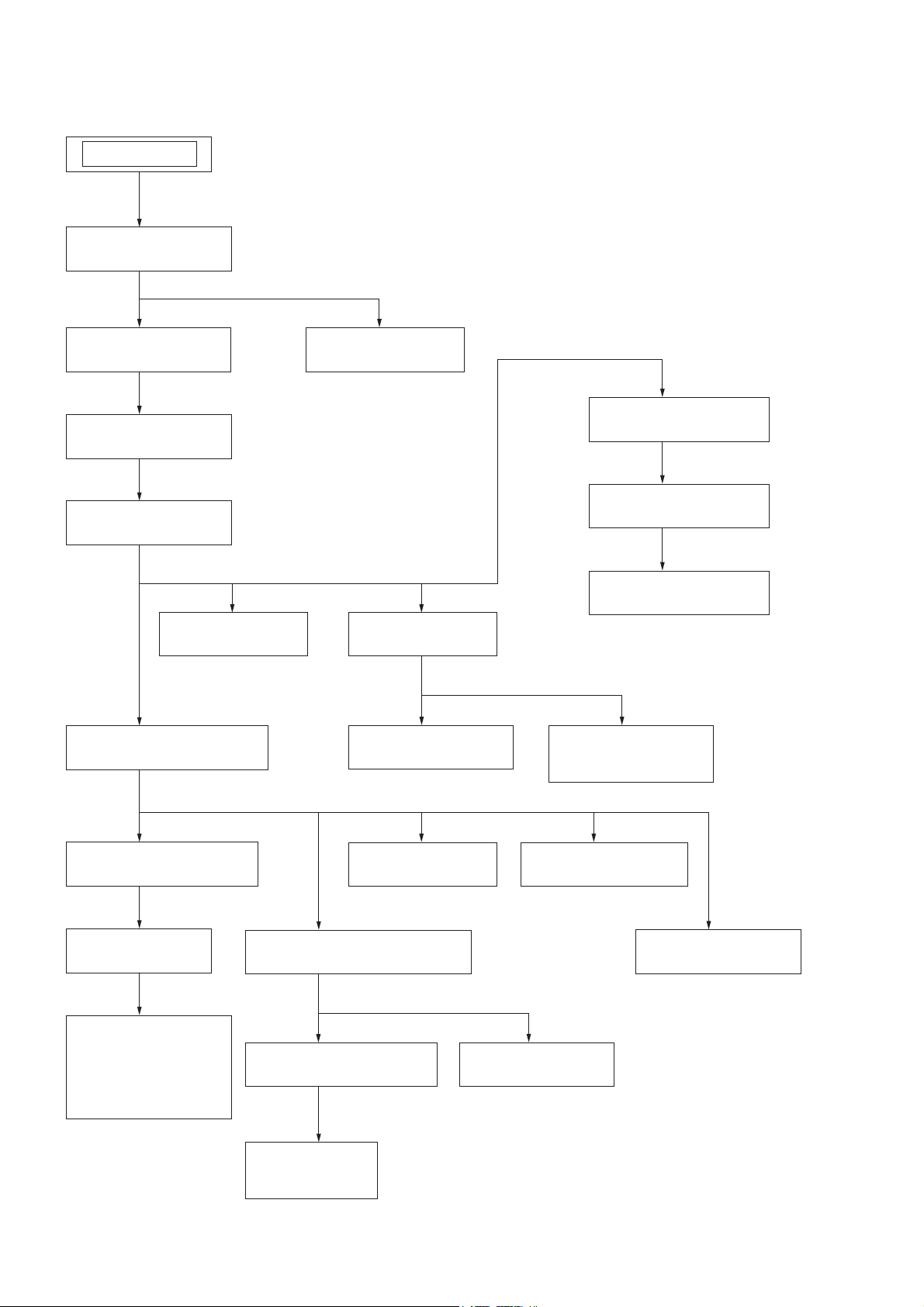
• This set can be disassembled in the order shown below.
SET
2-1. CASE
(Page 9)
2-3. TUNER ASSY
(Page 10)
2-4. LOADING PANEL
(Page 10)
2-5. DVD BLOCK
(Page 11)
2-17. DMB19 BOARD
(Page 17)
2-6. FRONT PANEL SECTION
(Page 11)
2-2. VOL-LED BOARD
(Page 9)
2-18. BASE UNIT
(Page 17)
2-19. OPTICAL PICK-UP
(Page 18)
2-21. SENSOR BOARD
(Page 19)
2-22. MOTOR (TB) BOARD
(Page 19)
2-23. MOTOR (LD) BOARD
(Page 20)
2-20. DRIVER BOARD,
SW BOARD
(Page 18)
2-7. BACK PANEL SECTION
(Page 12)
2-8. MAIN BOARD
(Page 12)
2-9. 2CH-AMP BOARD
(RV222D/RV222DL/
RV555D),
3CH-AMP BOARD
(RV333D/RV333DL)
(Page 13)
8
2-14. PANEL BOARD
(Page 15)
2-10. TAPE MECHANISM BLOCK
(Page 13)
2-11. JACK-MIC AMP BOARD
(Page 14)
2-12. LID (TC-L),
LID (TC-R)
(Page 14)
2-15. KEY-RIGHT BOARD
(Page 16)
2-16. KEY-LEFT BOARD
(Page 16)
2-13. TC AMP BOARD
(Page 15)
HCD-RV222D/RV222DL/RV333D/RV333DL/RV555D
Note: Follow the disassembly procedure in the numerical order given.
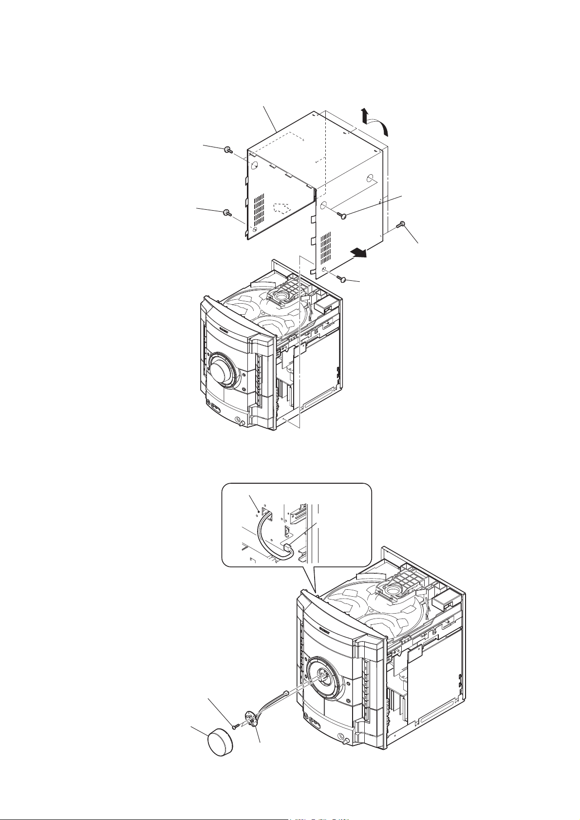
2-1. CASE
4 two screws
(case 3 TP2)
3 screw
(case 3 TP2)
9 case
7
8
2 two screws
(case 3 TP2)
6
1 screw
(case 3 TP2)
5 seven screws
(+BVTP 3 u8)
2-2. VOL-LED BOARD
1 knob (VOL) assy
PANEL board
3 CN302 (2P)
2 two screws
(+BVTP 2.6 (3-CR))
4 VOL-LED board
9
HCD-RV222D/RV222DL/RV333D/RV333DL/RV555D
2-3. TUNER ASSY
3 tuner assy
1 two screws
(+BVTT 3 u6)
2 wire (flat type) (9 core)
(CN081)
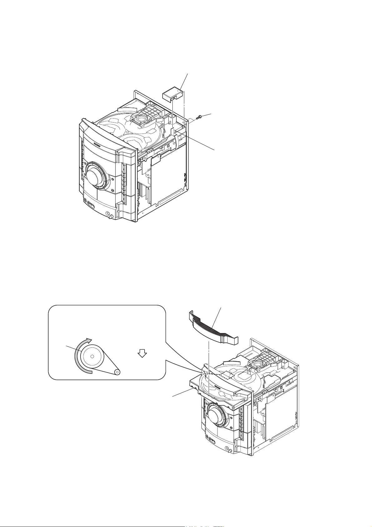
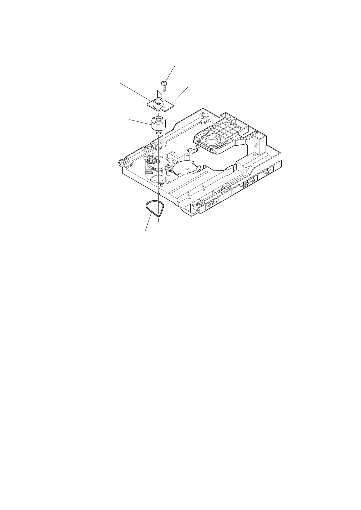
2-4. LOADING PANEL
CD mechanism deck (CDM74)
1
Turn the pulley to the direction of the arrow.
pulley
Front panel side
2
Pull-out the disc tray.
3
loading panel
10
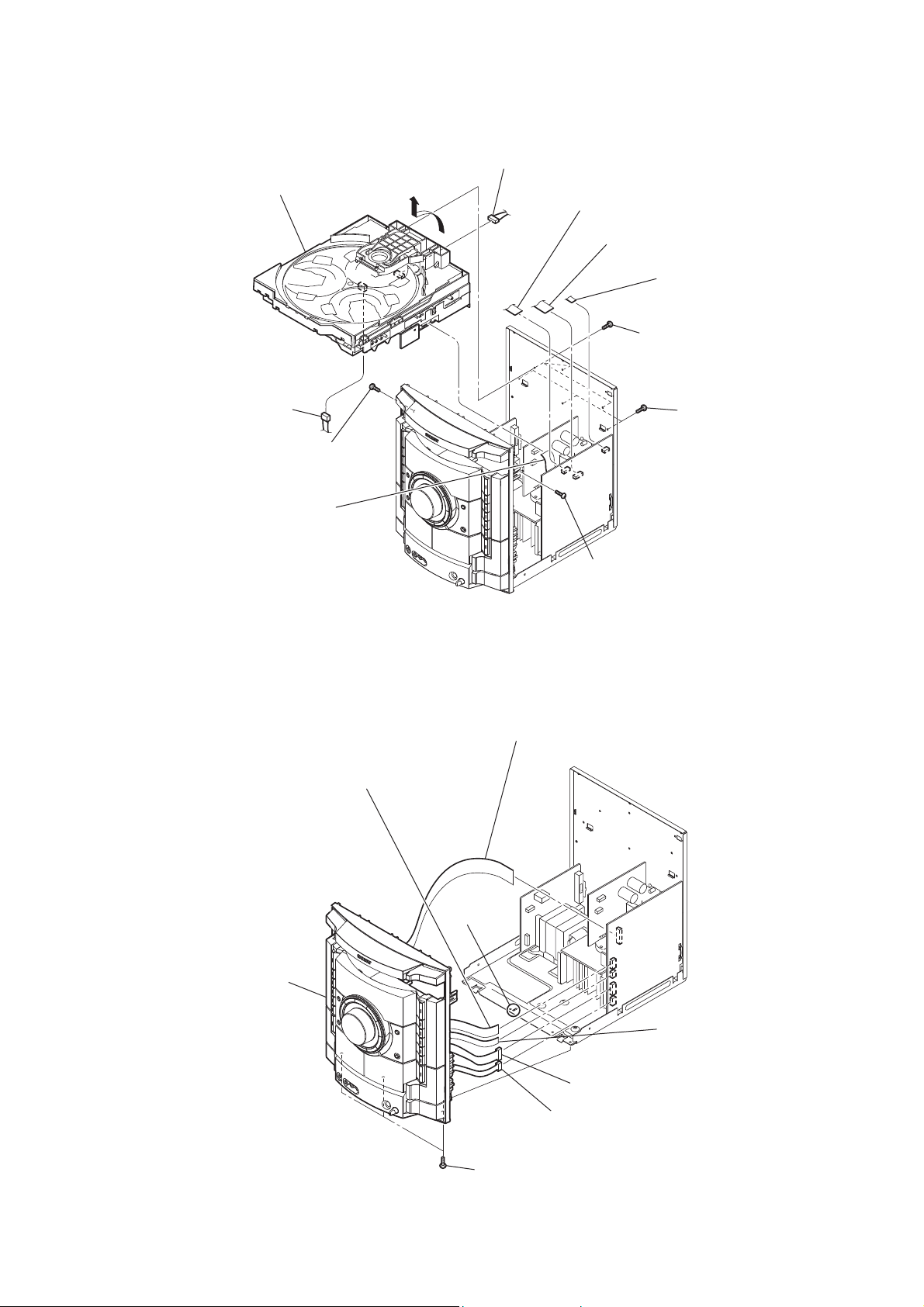
2-5. DVD BLOCK
qs DVD block
HCD-RV222D/RV222DL/RV333D/RV333DL/RV555D
7 CN601 (9P)
5
0 wire (flat type) (7 core)
(CN803)
9 wire (flat type) (9 core)
(CN605)
8 wire (flat type) (5 core)
(CN805)
4 three screws
(+BVTP 3 u8)
6 CN1103 (3P)
2 screw
(+BVTP 3 u8)
qa wire (flat type) (13 core)
(CN701)
2-6. FRONT PANEL SECTION
3 wire (flat type) (11 core)
(CN604)
3 three screws
(+BVTP 3 u8)
1 screw
(+BVTP 3 u8)
2 wire (flat type) (17 core)
(CN601)
8 front panel section
7 claw
4 wire (flat type) (11 core)
(CN802)
5 CN801 (11P)
6 CN603 (6P)
(EA, PH, RU, SP, SAF model)
1 three screws
(+BVTP 3 u6)
11
HCD-RV222D/RV222DL/RV333D/RV333DL/RV555D
d
Ver. 1.3
2-7. BACK PANEL SECTION
6 back panel section
5 CN960 (3P)
Arrange the wire as illustrated below in order to
prevent contact with the heat sink.
4 two screws
(+BVTP 3 u8)
(RV333D/RV333DL/RV555D)
3 two screws
(+BVTP 3 u8)
2 two screws
(+BVTP 3 u8)
1 four screws
(+BVTP 3 u8)
2-8. MAIN BOARD
1 CN002 (9P)
2 CN503 (8P) (RV222D/RV222DL/RV555D)
CN503 (9P) (RV333D/RV333DL)
5 REG board
4 screw
(+BVTP 3 u8)
7 CN958 (3P)
8 MAIN boar
6 two screws
(+BVTP 3 u8)
12
3 CN501 (6P) (RV222D/RV222DL/RV555D)
CN501 (8P) (RV333D/RV333DL)
HCD-RV222D/RV222DL/RV333D/RV333DL/RV555D
2-9. 2CH-AMP BOARD (RV222D/RV222DL/RV555D), 3CH-AMP BOARD (RV333D/RV333DL)
5 bracket (AMP)
2 two screws
3 screw
(+BVTP 3 u8)
(transistor)
6 2CH-AMP board (RV222D/RV222DL/RV555D)
3CH-AMP board (RV333D/RV333DL)
Ver. 1.3
1 CN001 (9P)
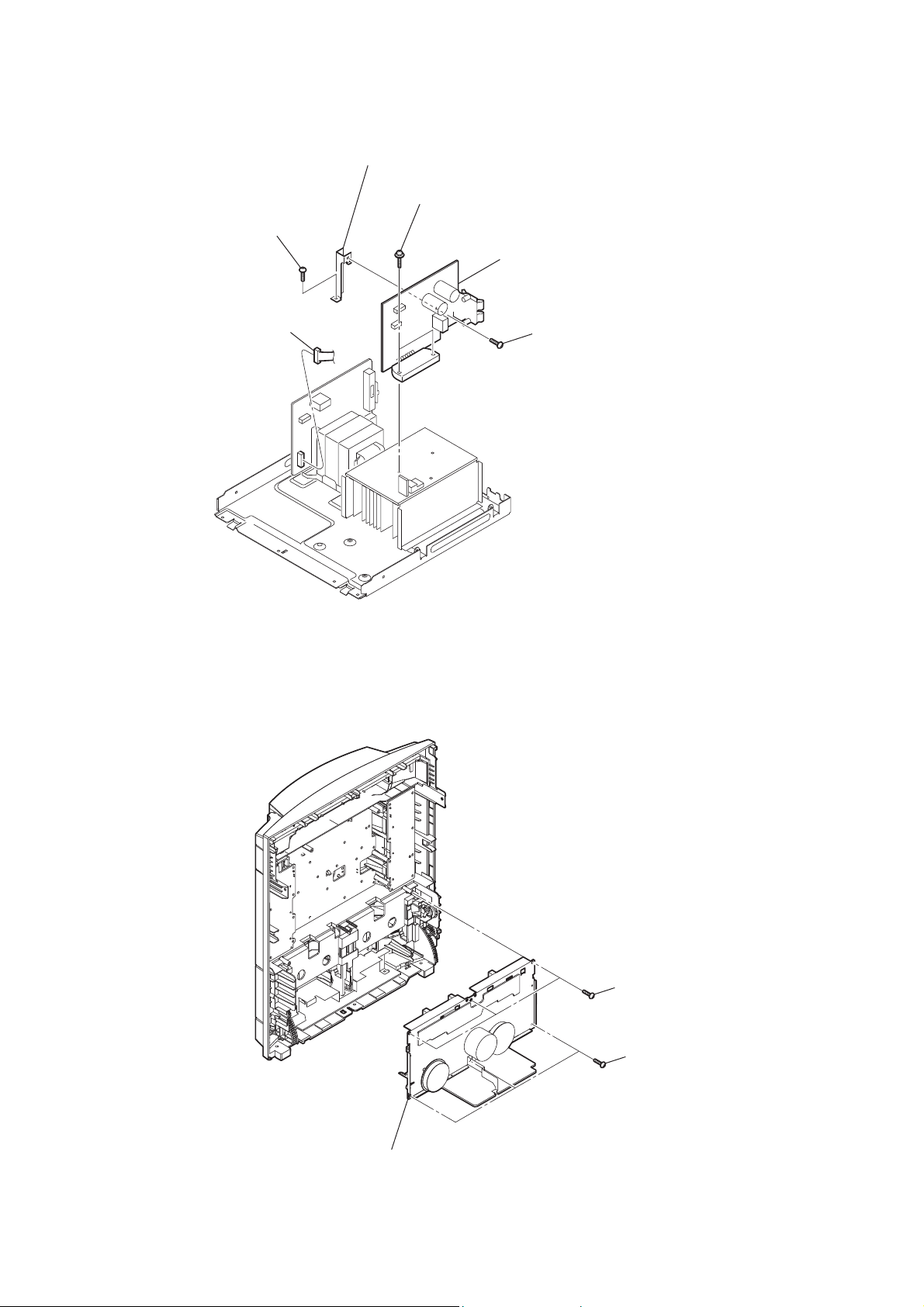
2-10. TAPE MECHANISM BLOCK
4 screw
(+BVTP 3 u8)
3 tape mechanism block
1 three screws
(+BV3 (3-CR))
2 three screws
(+BV3 (3-CR))
13
HCD-RV222D/RV222DL/RV333D/RV333DL/RV555D
2-11. JACK-MIC AMP BOARD
1 knob (MIC)
5 holder (JACK PWB)
2 screw
(+BV3 (3-CR))
7 JACK-MIC AMP board
2-12. LID (TC-L), LID (TC-R)
3 lid (TC-L)
3 screw
(+BV3 (3-CR))
6 sheet jack PWB
(Russian, South African model)
4 three screws
(+BVTP 3 u8)
1 damper
14
2 spring (TC-L)
6 lid (TC-R)
4 damper
front panel assy
5 spring (TC-R)
2-13. TC AMP BOARD
4 head lead fixed spring
HCD-RV222D/RV222DL/RV333D/RV333DL/RV555D
6 two screws
(+BTP 2 u6)
7 screw
(+BVTP 3 u8)
5 head lead fixed spring
3 Remove the four solders.
white
black
2 Remove the two solders.
2-14. PANEL BOARD
1 knob (VOL) assy
blue
red
8 bracket (PWB TCM)
yellow
9 TC AMP board
black
white
white
red
1 Remove the three solders.
tape mechanism deck
2 CN361 (2P)
8 PANEL board
3 CN351 (3P)
4 CN302 (2P)
5 three screws
(+BVTP 2.6 (3CR))
6 seven screws
(+BVTP 2.6 (3CR))
7 three screws
(+BVTP 2.6 (3CR))
15
HCD-RV222D/RV222DL/RV333D/RV333DL/RV555D
2-15. KEY-RIGHT BOARD
1 CN361 (2P)
2-16. KEY-LEFT BOARD
4 KEY-RIGHT board
1 CN351 (3P)
2 three screws
(+BVTP 2.6 (3CR))
3 four screws
(+BVTP 2.6 (3CR))
2 four screws
(+BVTP 2.6 (3CR))
16
3 three screws
(+BVTP 2.6 (3CR))
4 KEY-LEFT board

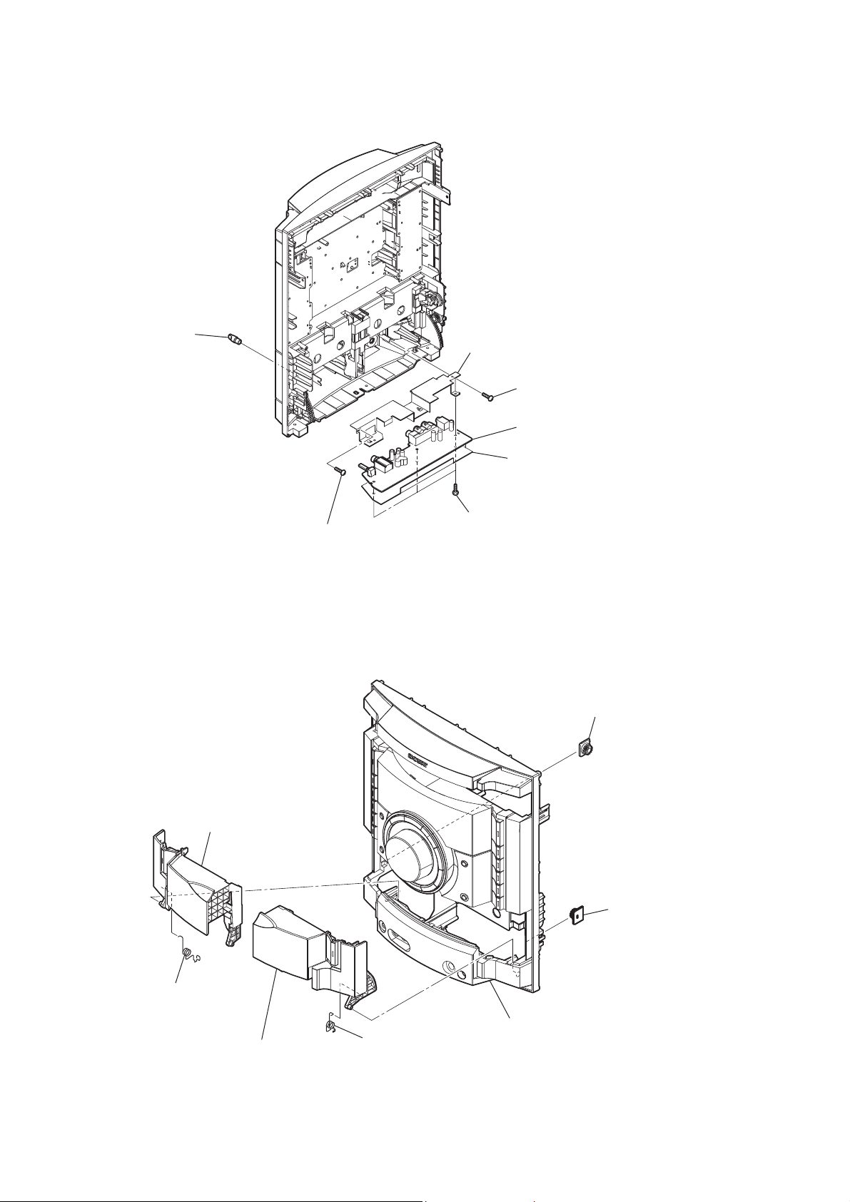
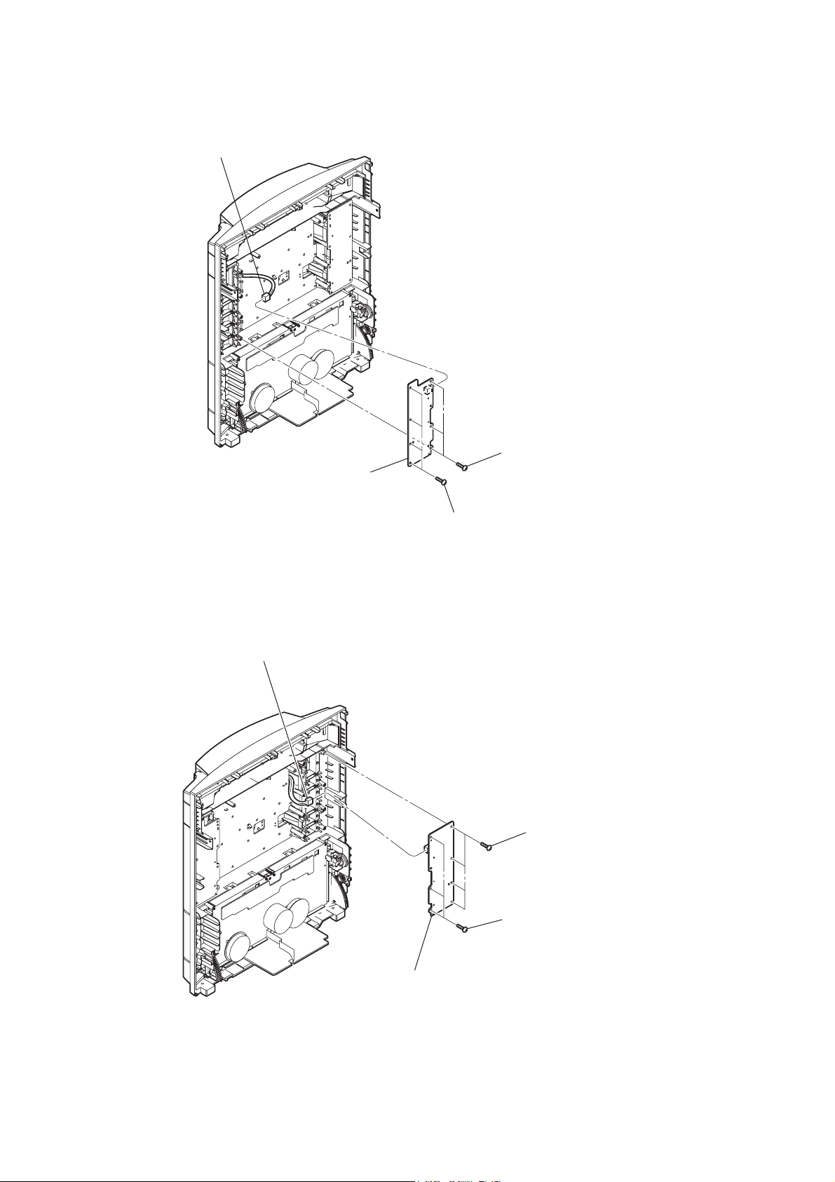
2-17. DMB19 BOARD
HCD-RV222D/RV222DL/RV333D/RV333DL/RV555D
3 two screws
(+BVTP 3 u8)
7 DMB19 board
5 wire (flat type) (24 core)
(CN101)
4 two screws
(+BVTP 3 u8)
6 CN201 (6P)
2 HOLD board
1 screw
(+BVTP 3 u8)
2-18. BASE UNIT
8 sub chassis
4 screw
(+BVTP 3 u8)
5 screw
(+BVTP 3 u8)
1 wire (flat type) (24 core)
(CN101)
6 screw
(+BVTP 3 u8)
7 clip
2 CN201 (6P)
3 screw
(+BVTP 3 u8)
9 floating screw
(+PTPWH M2.6)
0 base unit
DVD mechanism section
17
HCD-RV222D/RV222DL/RV333D/RV333DL/RV555D
2-19. OPTICAL PICK-UP
4 two insulators
2 two insulator screws
5
optical pick-up
6
holder (310)
1 two insulator screws
3 two insulators
2-20. DRIVER BOARD, SW BOARD
2 SW board
7 CN702 (5 core)
4 CN703 (4P)
6 DRIVER board
3 CN704 (2P)
18
1
screw
(+BTTP (M2.6))
5 two
screws
(+BTTP (M2.6))
2-21. SENSOR BOARD
HCD-RV222D/RV222DL/RV333D/RV333DL/RV555D
tray
floating
(+PTPWH M2.6)
floating
(+PTPWH M2.6)
gear (geneva)
screw
screw
(+BTTP (M2.6))
screw
SENSOR board
CN731
(3P)
belt (table)
floating
(+PTPWH M2.6)
screw
pulley (table)
2-22. MOTOR (TB) BOARD
table assy
2
stopper
1
4
5
3 two
screws
(+BTTP (M2.6))
2
stopper
6
table motor assy (M741)
MOTOR (TB) board
Remove the two solders of motor.
19
HCD-RV222D/RV222DL/RV333D/RV333DL/RV555D
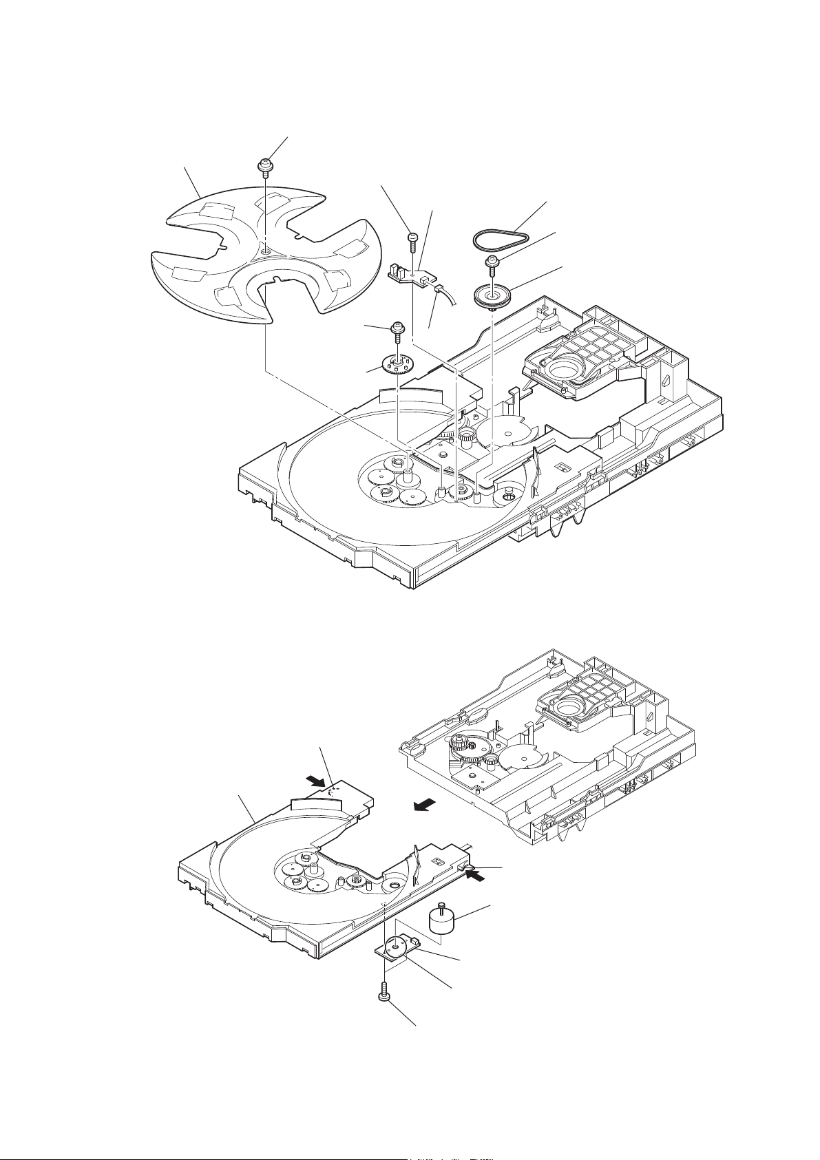
2-23. MOTOR (LD) BOARD
2 two
screws
(+BTTP (M2.6))
4
Remove the two solders of motor.
3
MOTOR (LD) board
5
loading motor assy (M751)
1
belt (loading)
20

HCD-RV222D/RV222DL/RV333D/RV333DL/RV555D
SECTION 3
TEST MODE
[COLD RESET]
The cold reset clears all data including preset data stored in the
RAM to initial conditions. Execute this mode when returning the
set to the customer.
Procedure:
1. Press the [
2. Press three buttons of [
multaneously.
3. The message “RESET” is displayed on the LCD display momentarily, then becomes standby states.
[TUNING STEP CHANGE] (E3, PH, SP models)
A step of AM tuning interval can be changed over between 9 kHz
and 10 kHz.
Procedure:
1. Press the [
2. Press the [TUNER/BAND] button to select “AM”.
3. Press the [
in the ECO mode at that time, any later operations are invalid.
These operations should be performed either in the DEMO
mode or while the clock is displayed.
4. Press the [
button.
5. The message “AM 9K STEP” or “AM 10K STEP” is displayed
on the LCD display, and thus the channel step is changed over.
[DVD SHIP MODE]
This mode moves the optical pick-up to the position durable to
vibration. Use this mode when returning the set to the customer
after repair.
Procedure:
1. Ensure that no disc is placed in the DVD tray.
2. Press the [
3. Press the [DVD] button to select “DVD”.
4. Press two buttons of [N] and [
5. The message “LOCK” is displayed on the LCD display, and
the DVD ship mode is set.
6. To release from the mode, disconnect the AC plug to turn the
power off.
] button to turn the power ON.
?/1
], [PRESET EQ] and [DISC 3] si-
?/1
] button to turn the power on.
?/1
] button to turn the power off. When the set is
?/1
] button while pressing the [y M/TUNING +]
?/1
] button to turn the power on.
?/1
] simultaneously.
?/1
[CHANGE-OVER FUNCTION OF SAT/VIDEO]
This mode is used to enable function of external input to change
over between SAT and VIDEO.
Procedure:
1. Press the [
2. Press two buttons of [VIDEO/SAT] and [
3. The message “SAT” or “VIDEO” is displayed on the LCD display, and the function of external input is changed over.
[DVD COLOR SYSTEM CHANGE]
(E3, PH, SP, EA models)
Color system change to video signal format (NTSC/PAL).
Procedure:
1. Press the [
2. Press the [FUNCTION] button to set the function “DVD”.
3. Press the [
in the ECO mode at that time, any later operations are invalid.
These operations should be performed either in the DEMO
mode or while the clock is displayed.
4. Press the [
5. The display of LCD display changes to “COLOR PAL” or
“COLOR NTSC”.
[DVD TRAY LOCK MODE]
This mode is used to unable to take sample disc out of tray in the
shop.
Procedure:
1. Press the [
2. Press the [DVD] button to select “DVD”.
3. Set disc on the DVD tray, press two buttons of [x] and [Z] for
5 seconds.
4. The message “LOCKED” is displayed on the LCD display and
the DVD tray is locked. (Even if pressing the [Z] button, the
message “LOCKED” is displayed on the LCD display and the
DVD tray is locked)
5. To release from this mode, press two buttons of [x] and [Z]
for 5 seconds.
6. The message “UNLOCKED” is displayed on the LCD display
and the DVD tray is unlocked.
] button to turn the power on.
?/1
] simultaneously.
?/1
] button to turn the power on.
?/1
] button to turn the power off. When the set is
?/1
] button while pressing the [X] button.
?/1
] button to turn the power on.
?/1
[DVD SHIP MODE & COLD RESET]
This mode is used to perform DVD ship (lock) mode and cold reset
simultaneously.
Procedure:
1. Ensure that no disc is placed in the DVD tray.
2. Press the [
3. Press the [DVD] button to select “DVD”.
4. Press three buttons of [x], [ENTER] and [
ously.
5. The message “RESET” is displayed on the LCD display momentarily, then becomes standby states.
6. To release from the mode, disconnect the AC plug to turn the
power off.
] button to turn the power on.
?/1
] simultane-
?/1
21
HCD-RV222D/RV222DL/RV333D/RV333DL/RV555D
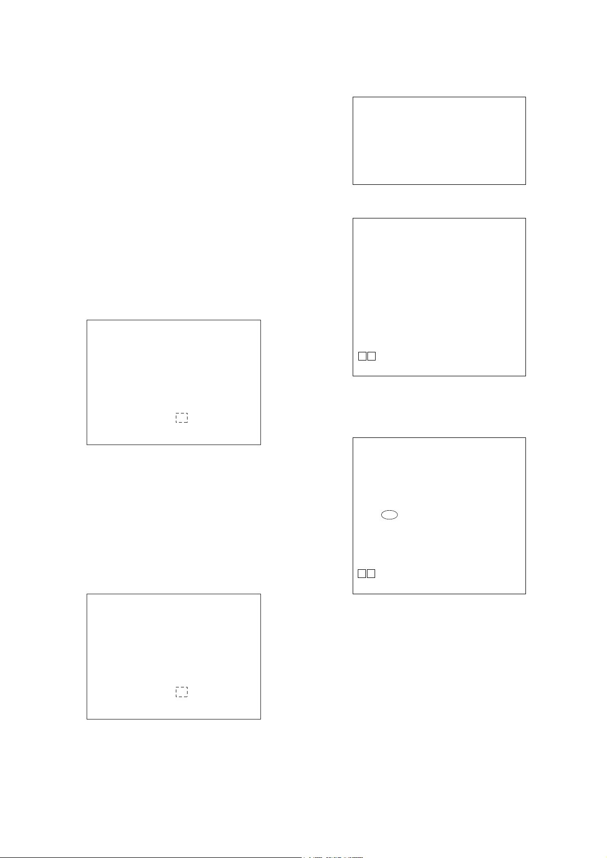
[PANEL TEST MODE]
This mode is used to check the LCD display, LEDs, keys, [MASTER VOLUME] jog, model, destination and software version.
Procedure:
1. Press [
] button to turn on the system.
?/1
2. Press [x] button, [ENTER] button and [DISPLAY] button simultaneously.
3. All LEDs and segments in LCD display are lighted up. All
LEDs are lighted.
4. Pressing the [DISC 1] button gets the date/version and DVD
Lib version shown on the LCD display.
G0100A0303
Version of the MC
G0044A0302
Version of the DVD-lib
included in the MC
Release date
Press [DISC 1] button.
Release date
Press [DISC 1] button.
5. Pressing the [DISC 2] button gets the destination shown on the
LCD display.
6. Pressing the [DISC 3] button causes the KEY TEST mode to
be entered with the Key Test display appearing on the LCD
display.
Key Test display
KEY 0 0 0
KEY 1
KEY 2
KEY 3
KEY 1 KEY 2 KEY 3
Count Button name Count Button name Count Button name
0—0—0—
1 ?/1 1 PRESET EQ 1 N
2 DISPLAY 2 ECHO 2 X
3 DVD 3
4 TAPE A/B 4
5 TUNER/BAND 5
6 VIDEO/SAT 6 REC TO TAPE 6 DISC 2
7
8
./
PRESET –
>/
PRESET +
m
TUNING –
BUSWOOFER
(RV333D only)
y M
TUNING +
7 x 7 DISC 3
8 GROOVE 8 ENTER
3
4
5 DISC 1
Z
OPEN/CLOSE
DISC SKIP/
EX-CHANGE
[COMMON TEST MODE]
This mode is used to check operations of the respective sections of
Amplifi er and VACS.
Procedure:
1. Press the [
] button to turn on the system.
?/1
2. Press [Z] button, [DISPLAY] button and [PRESET EQ] button simultaneously. The message “VACS0” appears on the
LCD display.
• Releasing from the mode:
3. Press the [
] button. “COLD RESET” is executed and then
?/1
the power is tuned off.
• Switching the EQ mode of Amplifi er:
4. Each time the [PRESET EQ] button is pressed, the EQ mode is
switched as follows:
ALL EQ MIN
ALL EQ MAX
ALL EQ FL
• Changing the GAIN of Amplifi er:
5. Pressing the [ECHO] button causes the LCD display to show
the message “VOLUME MIN” and the GAIN of Amplifi er to
be set to the minimum.
6. Pressing the [GROOVE] button causes the LCD display to
show the message “VOLUME MAX” and the GAIN of Amplifi er to be set to the maximum.
• Setting the VACS to ON or OFF:
7 Each time the [REC TO TAPE] button is pressed, the message
on the LCD display changes between “VACS ON” and “VACS
OFF” and the VACS is set to ON or OFF.
[VACS DISPLAY]
This mode is used to check the VACS level.
Procedure:
1. Press [
] button to turn on the system.
?/1
2. Press [DISPLAY] button, [PRESET EQ] button and [ENTER]
button simultaneously.
3. The message “V$ % #” appears on the LCD display.
“$” is the Conventional VACS level.
“%” is the present value of the input.
“#” is the peak value of the input.
7. To release from this mode, press three buttons in the same
manner as step 2, or disconnect the power cord.
22
HCD-RV222D/RV222DL/RV333D/RV333DL/RV555D
Ver. 1.3
[DVD SERVICE MODE]
1. GENERAL DESCRIPTION
The IOP measurement allows you to make diagnosis and adjustment simply by using the remote commander and monitor TV. The
instructions, diagnosis results, etc. are given on the on-screen display (OSD).
Be sure to execute the IOP measurement when a BU (Base Unit)
is replaced.
2. HOW TO ENTER TEST MODE
While pressing the [x] and [Z] buttons simultaneously, turn
[VOLUME] control in the direction of (+) with the DVD player
in power on.
The Test Mode starts, displayed “SERVICE IN” on this model
display then the menu shown below will be displayed on the TV
screen.
* The display of the “Model Name” of the “Remocon Diagnosis
Menu” change with the model and the destination. Refer to
below on the model name.
RV222D/RV222DL : RV0D
RV333D/RV333DL : RV2DS
RV555D : RV1D
Remocon Diagnosis Menu
0. External Chip Check
1. Servo Parameter Check
2. Drive Manual Operation
3. Emergency History
4. Version Information
1
Model Name
IF-con : Ver. XX.XX (XXXX)
Syscon : Ver. X.XXX
*1: Changes depending on destination
: RV2DS_XX
*
The menu above is the Remocon Diagnosis Menu screen which
consists of fi ve main functions. At the bottom of the menu screen,
the model name and IF-con version. To exit from the Test Mode,
press the [
] button on the remote commander.
?/1
3. EXECUTING IOP MEASUREMENT
In order to execute IOP measurement, the following standard procedures must be followed.
(2) Select “2. Drive Manual Operation” by pressing the [2] button
on the remote commander. The screen will appear as shown.
Drive Manual Operation
1. Servo Control
2. Track/Layer Jump
3. Manual Adjustment
4. Tray Aging Mode
5. MIRR time adjust
0. Return to Top Menu
(3) Select “3. Manual Adjustment” by pressing the [3] button on
the remote commander. The screen will appear as shown.
Manual Adjust
1. Track Balance Adjust:
2. Track Gain Adjust:
3. Focus Balance Adjust:
4. Focus Gain Adjust:
5. Eq Boost Adjust:
6. Iop:
7. TRV. Level:
8. S curve(FE) Level:
9. RFL(PI) Level:
0. MIRR Time:
Oo Change Value
[RETURN] Return to previous menu
(4) Select “6. IOP” by pressing the [6] button on the remote com-
mander.
(5) Wait until a hexadecimal number appear.
Manual Adjust
1. Track Balance Adjust:
2. Track Gain Adjust:
3. Focus Balance Adjust:
4. Focus Gain Adjust:
5. Eq Boost Adjust:
6. Iop. 4C:
7. TRV. Level:
8. S curve(FE) Level:
9. RFL(PI) Level:
0. MIRR Time:
(1) In power on, while pressing the [x] and [Z] buttons simulta-
neously, turn the [VOLUME] control in the direction of (+).
Remocon Diagnosis Menu
0. External Chip Check
1. Servo Parameter Check
2. Drive Manual Operation
3. Emergency History
4. Version Information
1
Model Name
IF-con : Ver. XX.XX (XXXX)
Syscon : Ver. X.XXX
*1: Changes depending on destination
: RV2DS_XX
*
Oo Change Value
[RETURN] Return to previous menu
(6) Convert each data from hexadecimal to decimal using conver-
sion table.
(7) Please fi nd the label on the rear of the BU (Base Unit).
The default IOP value is written in the label.
(8) Subtract between these two values.
(9) If the remainder is smaller than 93 (decimal), then it is OK.
However if the value is higher than 93, then the BU is defective and need to be change.
(10) Press the [RETURN] button on the remote commander to re-
turn back to previous menu.
(11) Press the [0] button on the remote commander to return to Top
Menu.
23
HCD-RV222D/RV222DL/RV333D/RV333DL/RV555D
4. EMERGENCY HISTORY
To check the emergency history, please follow the following procedure.
(1) From the Top Menu of Remocon Diagnosis Menu, select “3.
Emergency History Check” by pressing the [3] button on the
remote commander. The following screen appears on the onscreen display.
Emg. History Check
Laser Hours CD 999h 59min
01. 01 05 04 04
00 00 00 00 00 00 23 45
02. 02 02 01 01 00 A9 4B 00
00 00 00 00 00 00 23 45
[Next] Next Page [Prev] Prev Page
[O] Return to Top Menu
DVD 999h 59min
00 92 46 00
(2) You can check the total time when the laser is turned on during
playback of DVD and CD from the above menu. The maximum time, which can be displayed are 999h 59min.
(3) You can check the error code of latest 10 emergency history
from the above menu. To view the previous or next page of
emergency history, press [
] or [>] button on the remote
.
commander. The error code consists of the following three
blocks. The fi rst block indicates the error code. The second
block indicates the parameter and the third block indicates the
time of error code as shown below.
• Error Code
Emg. History Check
52: Open kick spindle error
60: Focus on error
61: Seek fail error
62: Read Q data/ID error
70: Lead in data read fail
71: TOC read time out (CD)
80: Can’t buffering
81: Unknown media type
4-1. Clear the Laser Hour
Press [
DISPLAY] button and then press [CLEAR] button on the
remote commander. The data for both CD and DVD data are reset.
Emg. History Check
Laser Hours CD 0h 0min
01. 01 05 04 04
00 00 00 00 00 00 23 45
02. 02 02 01 01 00 A9 4B 00
00 00 00 00 00 00 23 45
[Next] Next Page [Prev] Prev Page
[O] Return to Top Menu
DVD 0h 0min
00 92 46 00
4-2. Clear the Emergency History
Press [DVD TOP MENU] button and then press [CLEAR] button
on the remote commander. The error code for all emergency history would be reset.
Emg. History Check
Laser Hours CD 999h 59min
DVD 999h 59min
Laser Hours CD 999h 59min
*1 *2
01. 01 05 04 04
00 00 00 00 00 00 23 45
02. 02 02 01 01 00 A9 4B 00
00 00 00 00 00 00 23 45
[Next] Next Page [Prev] Prev Page
[O] Return to Top Menu
DVD 999h 59min
00 92 46 00
*3
*1 : Error Code
*2 : Parameter of error code
*3 : Time of error code
The meaning of error code is as below:
01: Communication error (No reply from syscon)
02: Syscon hung up
03: Power OFF request when syscon hung up
19: Thermal shutdown
24: MoveSledHome error
25: Mechanical move error (5 Changer)
26: Mechanical move stack error
30: DC motor adjustment error
31: DPD offset adjustment error
32: TE balance adjustment error
33: TE sensor adjustment error
34: TE loop gain adjustment error
35: FE loop gain adjustment error
36: Bad jitter after adjustment
40: Focus NG
42: Focus layer jump NG
51: Spindle stop error
01. 00 00 00 00
00 00 00 00 00 00 00 00
02. 00 00 00 00 00 00 00 00
00 00 00 00 00 00 00 00
[Next] Next Page [Prev] Prev Page
[O] Return to Top Menu
00 00 00 00
4-3. Clear the Initialize Setup Data
Press [DVD MENU] button and then press [CLEAR] button on the
remote commander.
Emg. History Check
Laser Hours CD 999h 59min
[Next] Next Page [Prev] Prev Page
[O] Return to Top Menu
DVD 999h 59min
initialize setup data...
24

HCD-RV222D/RV222DL/RV333D/RV333DL/RV555D
4-4. Return to the Top Menu of Remocon Diagnosis
Menu
Press [0] button on the remote commander.
5. CHECK VERSION INFORMATION
To check the version information, please follow the following procedure.
(1) From the Top Menu of Remocon Diagnosis Menu, select “4.
Version Information” by pressing the [4] button on the remote
commander. The following screen appears on the on-screen
display.
Version information
Firm (Main) : Ver. xxxxx
Firm (Sub) : xxxxx
RISC : xxxxx
8032 : xxxxx
Audio DSP : xxxxx
Servo DSP : xxxxx
[O] Return to Top Menu
To return to the Top Menu of Remocon Diagnosis Menu, press
[0] button on the remote commander.
[TCM OFF LINE]
With the TC mechanism offl ine, the power can be turned on.
Procedure:
1. Press the [
2. Press three buttons of [REC TO TAPE], [DISC 3] and [
] button to turn the set off.
?/1
?/1
simultaneously.
3. The message “TC OFFLINE” appears on the LCD display for
a moment and the system power is turned on.
4. To exit from this mode, press the [
] button to turn the set
?/1
off.
[DVD OFF LINE]
With the CDM offl ine, the power can be turned on.
Procedure:
1. Press the [
2. Press three buttons of [GROOVE], [DISC 1] and [
] button to turn the set off.
?/1
?/1
] simul-
taneously.
3. The message “DVD OFFLINE” appears on the LCD display
for a moment and the system power is turned on.
4. To exit from this mode, press the [
] button to turn the set
?/1
off.
]
25
HCD-RV222D/RV222DL/RV333D/RV333DL/RV555D
SECTION 4
ELECTRICAL ADJUSTMENTS
TUNER SECTION
0 dB = 1 μV
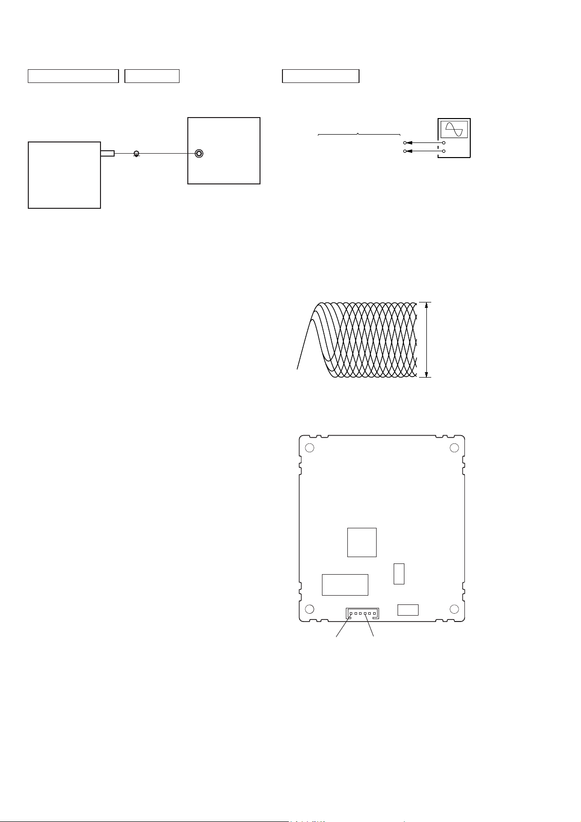
[FM TUNE LEVEL CHECK]
FM signal generator
SET
OUT (75 :)
Procedure:
1. Turn the power on.
2. Input the following signal from Signal Generator to FM antenna input directly.
* Carrier Freq : A = 87.5 MHz, B = 98 MHz, C = 108 MHz
Deviation : 75 kHz
Modulation : 1 kHz
ANT input : 35 dBu (EMF)
Note: Please use 75 ohm “coaxial cable” to connect SG and the set. You
cannot use video cable for checking.
Please use SG whose output impedance is 75 ohm.
DVD SECTION
[RF LEVEL CHECK]
oscilloscope
DMB19 board
CN105 pin 6 (RFMON)
CN105 pin 3 (GND)
Procedure:
1. Connect an oscilloscope to CN105 pin 6 (RFMON) and
CN105 pin 3 (GND) on the DMB19 board.
2. Turn the power on.
3. Load a disc (HLX-503 (J-6090-069-A)) and playback.
4. Confi rm that oscilloscope waveform is clear and check if RF
signal level is correct or not.
Note: Clear RF signal waveform means that the shape “◊” can be clearly
distinguished at the center of the waveform.
RFMON signal waveform
+
–
VOLT/DIV: 100 mV
TIME/DIV: 500 ns
level: 0.5 ± 0.3 Vp-p
3. Set to FM tuner function and tune A, B and C signals.
4. Confi rm “TUNED” is lit on the display for A, B and C signals.
The mark of “TUNED” means “The selected station signal is received in good condition.”
Connecting Location: DMB19 board
– DMB19 BOARD (SIDE A) –
IC101
IC104
CN105 pin 6
(RFMON)
CN105
CN105 pin 3
(GND)
CN1103
CN1104
26
• Circuit Boards Location
SECTION 5
DIAGRAMS
HCD-RV222D/RV222DL/RV333D/RV333DL/RV555D
Ver. 1.3
PT-0D board (RV222D/RV222DL)
PT-1D/2D board (RV333D/RV333DL/RV555D)
KEY-LEFT board
PANEL board
VOL-LED board
KEY-RIGHT board
2CH-AMP board (RV222D/RV222DL/RV555D)
3CH-AMP board (RV333D/RV333DL)
TUNER board
MAIN board
REG2 board
REG board
SW board
MOTOR (LD) board
MOTOR (TB) board
SENSOR board
DMB19 board
DRIVER board
TC AMP board
JACK-MIC AMP board
HCD-RV222D/RV222DL/RV333D/RV333DL/RV555D
2727
HCD-RV222D/RV222DL/RV333D/RV333DL/RV555D
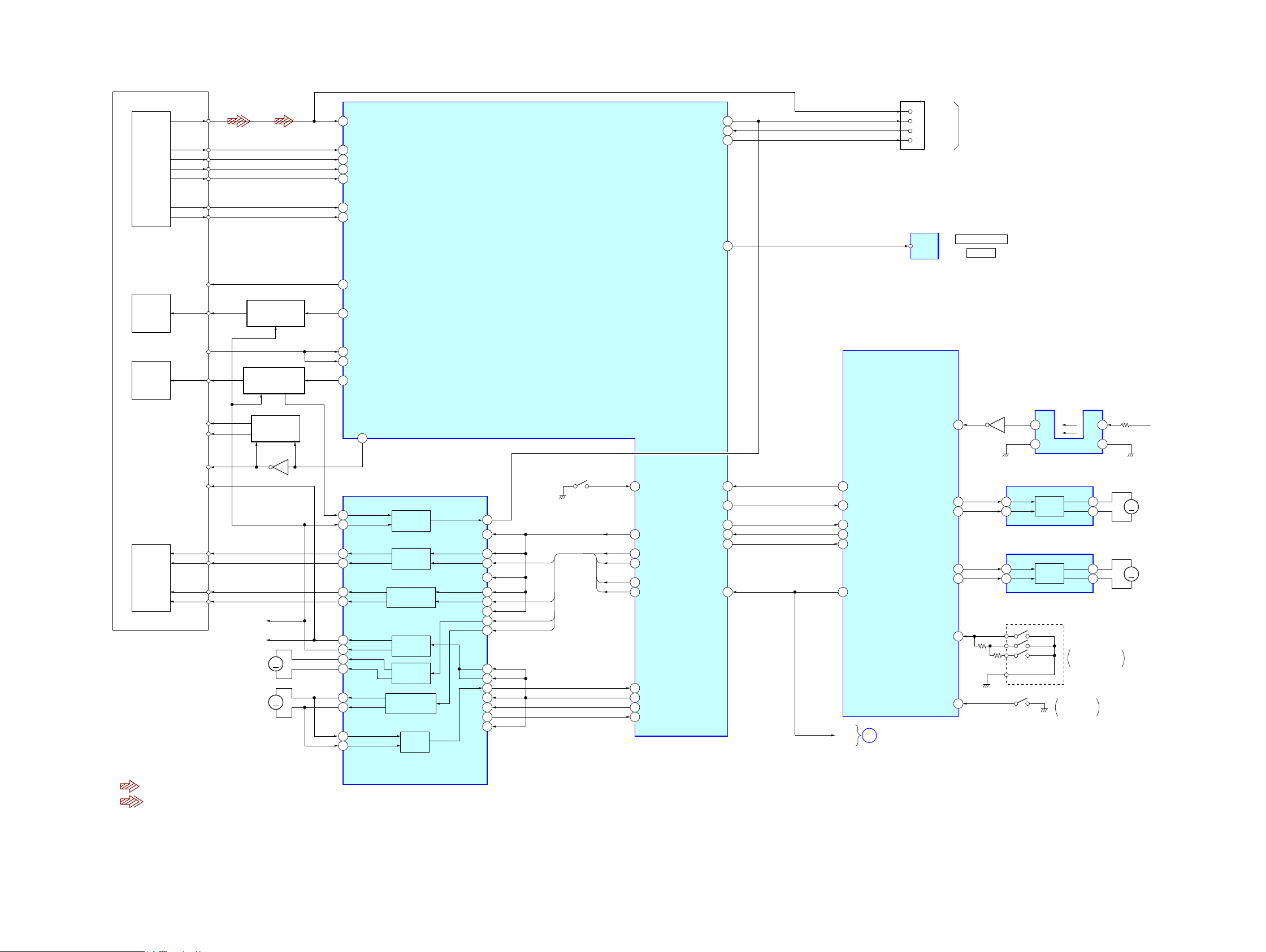
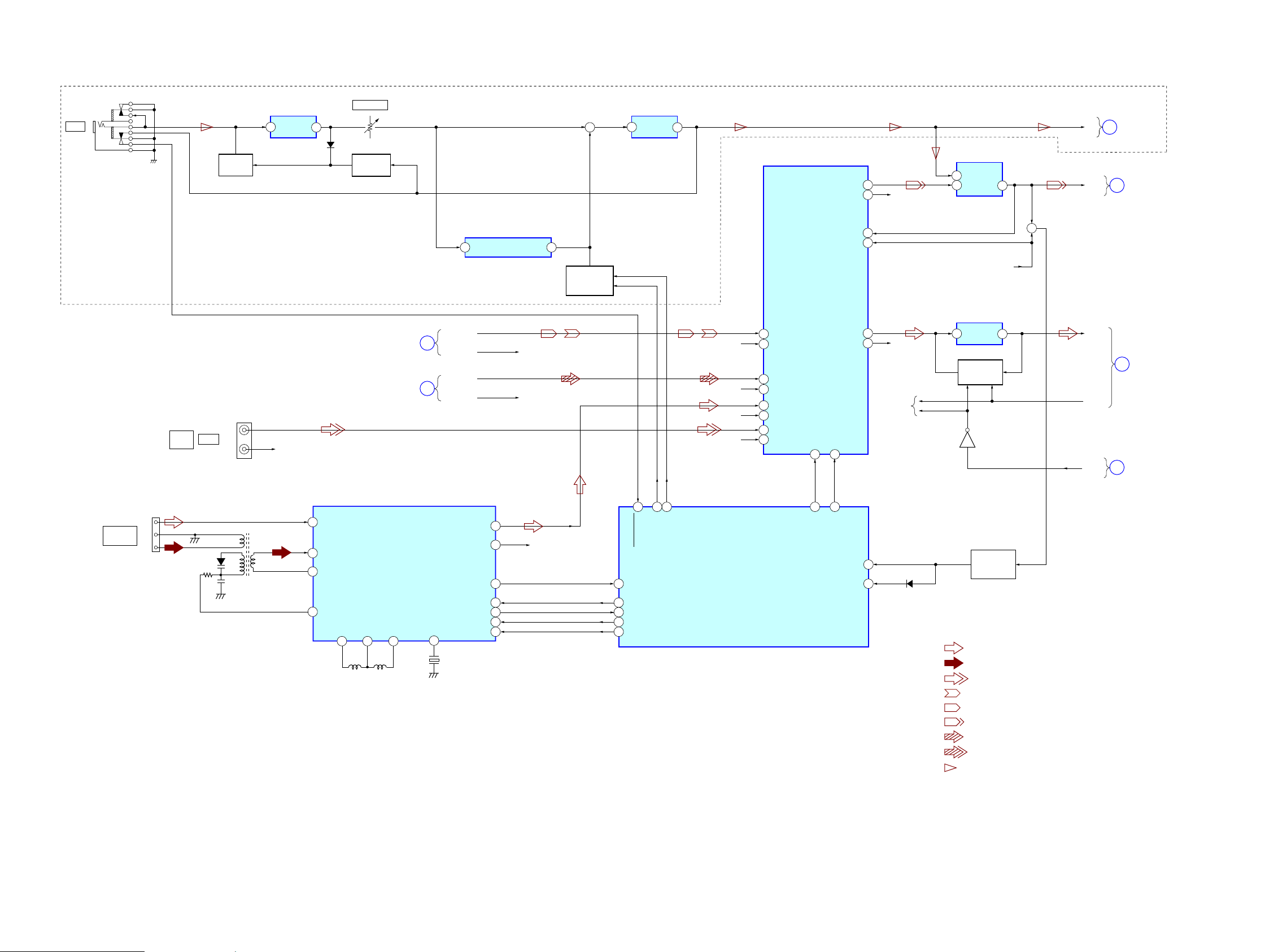
5-1. BLOCK DIAGRAM – RF Section –
DETECTOR
RF
VOA/A
VOB/B
VOC/C
VOD/D
RFIP IOPMON/OPINP
125
RF-A
1
RF-B
2
RF-C
3
RF-D
4
CN105
6
RFMON
127
RX
89
TX
91
5
2
1
V2REFO
RXD
TXD
(SERVICE JIG)
VOE/E+G
VOF/F+H
OPTICAL PICK-UP
BLOCK
VC
LASER
DIODE
(FOR CD)
LASER
DIODE
(FOR DVD)
2AXIS
DEVICE
FOCUS/
TRACKING
COIL
LD (780)
LD (650)
VR (650)
VR (780)
MSW
(LO: DVD, HI:CD)
VCC
FCS+
FCS-
TRK+
TRK-
PD
(SLED MOTOR)
(SPINDLE MOTOR)
x R-ch is omitted due to same as L-ch.
x SIGNAL PATH
: CD/DVD PLAY (AUDIO)
: DVD PLAY/VIDEO IN (VIDEO)
Q102 (1/2)
LD DRIVE
CONTROL (FOR CD)
Q102 (2/2)
LD DRIVE
CONTROL (FOR DVD)
Q1101
PD VOLUME
CONTROL
Q103
REG02
REG01
MM
MM
SP+
SP-
SLSL+
IOP
RF-E
5
RF-F
6
V20
12
LD01
17
MDI1
15
MDI2
16
LD02
18
MSW
54
FOCUS/TRACKING DRIVER,
SPINDLE/SLED MOTOR DRIVER
42
41
36
37
35
34
32
31
30
29
27
28
46
47
IC201
BUFFER
FOCUS COIL
DRIVE
TRACKING COIL
DRIVE
BUFFER
SLED MOTOR
DRIVE
SPINDLE MOTOR
DRIVE
BUFFER
CD/DVD RF AMP,
FOCUS/TRACKING ERROR AMP,
DVD SYSTEM PROCESSOR,
DIGITAL SERVO PROCESSOR
IC101 (1/2)
40
43
48
1
12
3
4
9
10
13
6
7
45
19
20
22
21
VREFO
FOO
TRO
FMO
DMO
SPFG
(LIMITSW)
FMO
FOO
DMO
TRO
GPIO
118
V14/VREFO
13
FMO
21
FOO
25
DMO
20
TRO
24
128
SPFG/OPINN
GPIO
116
MUTE4
22
94
GPIO
93
SPDIF IN
SYSTEM CONTROL
PRST#
IFSCK
IFSDO
IFSDI
IFCS#
IFBSY
43
40
41
35
89
87
XSYSRST
IFSCK
IFSDO
IFSDI
XIFCS
XIBSY
O-MTK-MTRST
38
I-MTK-CLK
46
I-MTK-DATA
45
O-MTK-DATA
44
I-DVD-XIFCS
39
O-MTK-IFBSY
37
BB-ON
A
(Page 30)
OPTICAL
TRANSMITTER
IC803
DVD DIGITAL OUT
OPTICAL
IC601 (1/6)
TABLE ADDRESS SENSOR
3
4
MOTOR
MOTOR
IC701
DRIVE
IC712
DRIVE
IC731
OUT2
2
OUT1
4
OUT2
2
OUT1
4
RE701
ROTARY ENCODER
DISC TRAY
ADDRESS DETECT
S751
OPEN/CLOSE
DETECT
1
2
Q731
I-CDM_ENC
48
LD MOTOR DRIVER
40
43
42
41
59
49
FIN
7
RIN
9
TBL MOTOR DRIVER
FIN
7
RIN
9
I-CDM-TBL-ADR-SW M+9V
O-CDM_LM-F
O-CDM_LM-R
O-CDM_TM-F
O-CDM_TM-R
I-CDM-OPEN-SW
AUDIO
SECTION
MM
MM
M751
(LOADING)
M741
(TABLE)
HCD-RV222D/RV222DL/RV333D/RV333DL/RV555D
2828
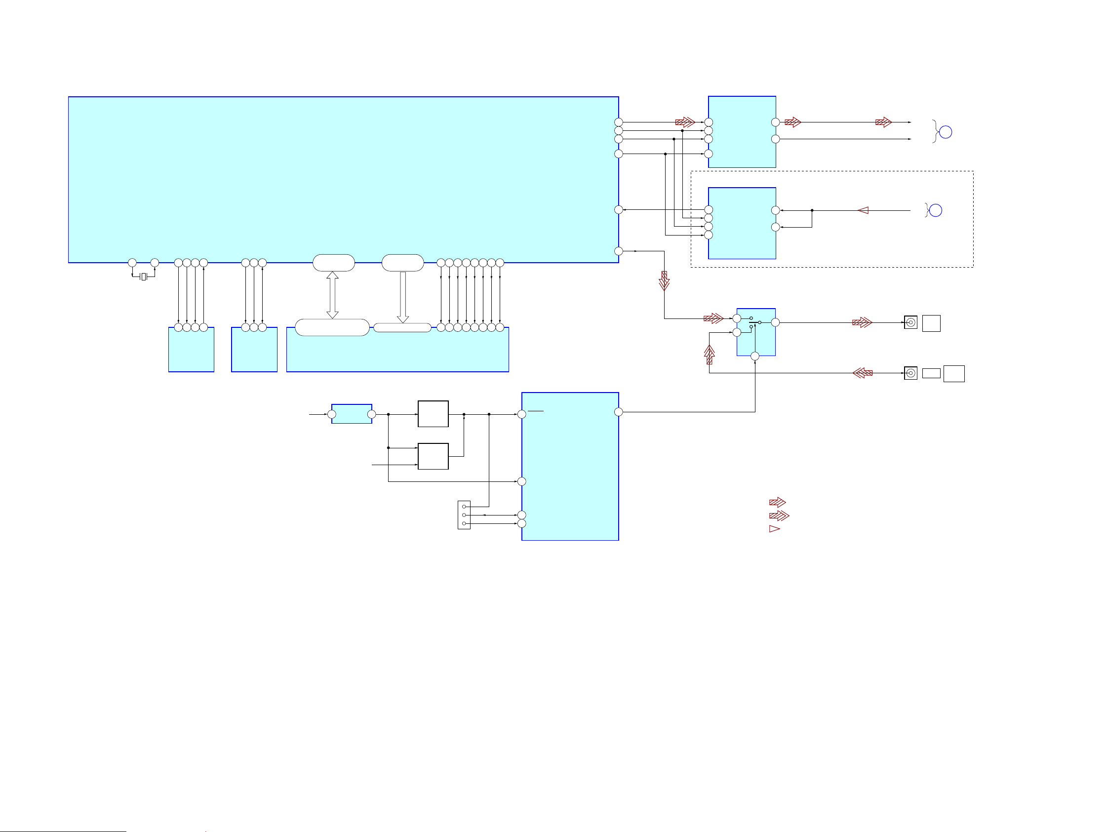
5-2. BLOCK DIAGRAM – DVD OUT Section –
D/A CONVERTER
IC4602
HCD-RV222D/RV222DL/RV333D/RV333DL/RV555D
XTALO
X101
0+]
910
XTALI
6)B&6
6)B',
6)B&.
36 38 39 14
5
1 6
SI
SCK
_CS
6)520
IC102
6)B'2
2
SO
EEWP
SCL
26 33 34
7
6
WE
SCL
EEPROM
IC103
GPIO
GPIO
GPIO
GPIO
DVD SYSTEM PROCESSOR
IC101 (2/2)
GPIO19
SDA
5
SDA
RD0–RD15
±±
±±
DQ0 – DQ15
+3.3V
VDD OUT
RESET
IC701
RA0–RA11
±
íí
A0 – A11
64M SDRAM
IC104
12
RWE#
75 77 76
16 17 20
WE
RESET
DRIVE
Q706
RAS#
18
RAS
CAS#
BA0
RCLK
66 78 55 65
38 15
BA0
CLK
CAS
DQM0
39
LDQM
DQM1
80
21
UDQM
BA1
BA1
90
RESET
SYSTEM CONTROL
IC601 (2/6)
O-VIDEO-SW
CVBS
ABCK
115
ALRCK
119
ACLK
114
ADIN
106
99
84
ASDATA0
120
1
2
3
4
9
8
7
6
SDATA
SCLK
LRCK
MCLK
DOUT
BCK
LRCK
SCKI
AOUT_L
AOUT_R
A/D CONVERTER
IC4601
9,'(26:,7&+
DRIVER
IC891
6
4
1
VINL
VINR
8
5
13
14
2
DVD_L
C
B
(Page 30)
AUDIO
SECTION
DVD_R
($3+586$)6302'(/
MIC
(Page 30)
J801
VIDEO
OUT
J251 (1/2)
VIDEO
VIDEO
INPUT
AUDIO
SECTION
VSTBY
INITIAL
RESET
4
RESET
SI-SO
)/0'
CN602
4
5
1
10
89
93
I-AC-CUT
SI/SO
)/0'
x R-ch is omitted due to same as L-ch.
x6,*1$/3$7+
: CD/DVD PLAY (AUDIO)
: DVD PLAY/VIDEO IN (VIDEO)
: MIC
x Abbreviation
EA : Saudi Arabia model
3+ 3KLOLSSLQHVPRGHO
RU : Russian model
6$)6RXWK$IULFDQPRGHO
63 6LQJDSRUHPRGHO
HCD-RV222D/RV222DL/RV333D/RV333DL/RV555D
2929
HCD-RV222D/RV222DL/RV333D/RV333DL/RV555D
5-3. BLOCK DIAGRAM – AUDIO Section –
VR261
MIC LEVEL
MIC DETECT
Q262
J261
MIC
MIC_SW
MUTING
Q261
5
+IN
MIC AMP
IC261 (1/2)
OUT
7
D263
EA, PH, RU, SAF, SP MODEL
MIC AMP
IC261 (2/2)
2
-IN
OUT
+
1
INPUT SELECT, TONE CONTROL,
ELECTRICAL VOLUME
IC801
SEL-L
SEL-R
10
9
R-CH
MIC-LINE MIX
IC871
-IN
2
3
+IN
OUT
1
MIC
REC-L
C
(Page 29)
E
DVD OUT
SECTION
TAPE
SECTION
(Page 31)
ANTENNA
FM/AM
GND
FM
AM
CN082
VIDEO
IN
AUDIO
D081
J251 (2/2)
L
R
L081
R-CH
30
1
2
3
ANT1
AM ANT
AM REF
AMVT
L1
L097
TAPE
SECTION
(Page 31)
DVD OUT
SECTION
(Page 29)
FM/AM FRONT-END
IF AMP, DET, FM MPX
IC081
VREF2
L2
262524
L098
D
B
16
DIGITAL ECHO
IC262
LPF1IN
2
TAPE_L
TAPE_R
DVD_L
DVD_R
L-OUT
9
10
R-OUT R-CH
13 31
SD OUT I-SD
DI
20
DO
21
CL
CLK IN
X081
32.768kHz
19
CE
18
LPF2OUT
R-CH
R-CH
9
ECHO GAIN
CONTROL
Q264–269
28
26
27
29
76
I-MIC-DETECT
O-TU-DO
I-TU-DI
O-TU-CLK
O-TU-CE
2
1
ECHO-G2
ECH-G1
R-CH
R-CH
R-CH
R-CH
SYSTEM CONTROL
IC601 (3/6)
1
2
5
6
3
4
7
8
TAPE-L
TAPE-R
CD-L
CD-R
TUNER-L
TUNER-R
AUDIO-L
AUDIO-R
SDATA
26 25
34 36
O-VOL-DATA
ECO-LEVEL
I-AUDIO-LEVEL
VOL-L
VOL-R
OUT-L
OUT-R
SCLK
O-VOL-CLK
R-CH
+
OUT-L
AMP
F
SECTION
(Page 32)
HP-LR
A
RF
SECTION
BB-ON
11
12
EQ AMP
IC802
23
R-CH
19
R-CH
31
+IN OUT
EQ SWITCH
Q829,831
Q833
(Page 28)
63
57
D885
AUDIO LEVEL,
DETECT AMP
Q885,886
x R-ch is omitted due to same as L-ch.
x SIGNAL PATH
: FM
: AM
: AUDIO IN
: TAPE PLAY (DECK A)
: TAPE PLAY (DECK B)
: TAPE REC
: CD/DVD PLAY (AUDIO)
: DVD PLAY/VIDEO IN (VIDEO)
: MIC
x Abbreviation
EA : Saudi Arabia model
PH : Philippines model
RU : Russian model
SAF : South African model
SP : Singapore model
HCD-RV222D/RV222DL/RV333D/RV333DL/RV555D
3030
 Loading...