

Sony 85P, 80P, 70P, 70AP, HVR-1500 User Manual
...
DIGITAL HD VIDEOCASSETTE
RECORDER
HVR-1500
HVR-1500A
DIGITAL VIDEOCASSETTE
RECORDER
DIGITAL VIDEOCASSETTE PLAYER
DSR-60/60P
DSR-1600/1600P
DSR-1600A/1600AP
VIDEO DISK RECORDER
DSR-70/70P
DSR-70A/70AP
DSR-DR1000/DR1000P
DSR-DR1000A/DR1000AP
DSR-80/80P
DSR-85/85P
DSR-1500/1500P
DSR-1500A/1500AP
DSR-1800/1800P
DSR-1800A/1800AP
DSR-2000/2000P
DSR-2000A/2000AP
PROTOCOL MANUAL
1st Edition (Revised 8)

COPYRIGHT NOTICE
Copyright © by Sony Corporation.
All rights reserved. The copyright on all matters
described in this manual belongs to Sony Corporation,
and the contents are intended for use by purchasers of
subject equipment.
Furthermore, Sony Corporation reserves the right to
revise this publication and to make changes from time to
time in the content hereof without obligation of Sony
Corporation to notify any person or organization of such
revision or changes.
DSR Series

Table of Contents
1. Summary ................................................... 1
2. Interface System Overview ...................... 1
3. Command Block Format (CMD Block) .... 2
3-1. VTP Command .................................................................. 2
3-2. DSR-DR1000/A DISK Command ..................................... 3
4. Connector Pin Assignment ..................... 7
5. Communication Protocol ......................... 8
6. Command .................................................. 9
6-1. Command Table (for Cassette Recorder/Player) ............... 9
6-2. Command Table (for Disk Recorder) .............................. 15
6-3.
Command Table (for DSR-DR1000/A Disk Command) ....
20
7. Protocol Command ................................ 21
7-1. VTR Command ................................................................ 21
7-2. DSR-DR1000/A Disk Command (Ver 1.10 or later) ...... 54
7-3. Items supported from DSR-DR1000/A disk command
V2.00 ............................................................................... 72
7-4. Special Commands for HVR Series ................................ 75
7-4-1. Command Table ..................................................... 75
7-4-2. Detailed Description of Commands ....................... 75
8. Time Data Format ................................... 77
9. Appendix-1 .............................................. 77
10. Appendix-2 .............................................. 78
11. Appendix-3 .............................................. 79
DSR series
1


1. Summary
The DSR series VTR, Remote Control Connector Panel, incorporate with a 9-pin D-Subminiature
connectors for REMOTE.
This connector is utilized for a serial control system.
The definition of CONTROLLER and DEVICE is shown in the follows,
“CONTROLLER” means the unit which controls VTR.
“DEVICE” means the unit (VTR) which is controlled.
Example 1)
When the DSR series VTR is connected by REMOTE (9-pin) connector, the VTR as the recorder
means CONTROLLER and the VTR as the player means DEVICE.
Example 2)
When the editing controller is connected with one or plural DSR series VTR (s), this editing controller is CONTROLLER and all VTRs are DEVICEs.
2. Interface System Overview
. Conforming to EIA RS-422A.
. Full duplex communications channel is utilized.
. Data is transmitted asynchronously, bit serial, word serial with data exchange between devices.
. Standard transmission rate on the interface bus is 38.4 kilobits per second (kb/s).
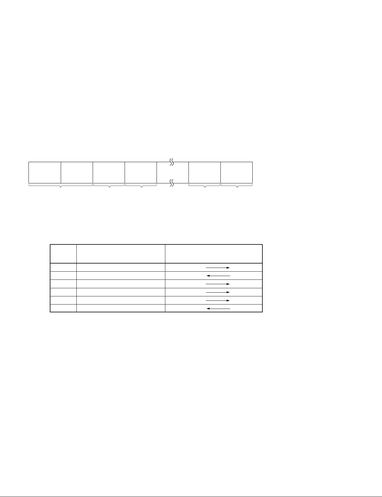
. The data word utilized by the interface system is as follows :
START
BIT
D0
(LSB)
D1 D2 D3 D4 D5 D6 D7
(MSB)
PARITY STOP
BIT
. 1 START BIT + 8 DATA BITs + 1 PARITY BIT + 1 STOP BIT.
ODD parity : The total of D0 + D1 +..... D7 + Parity bit equals an odd number.
(MARK)
(SPACE)
DSR Series
1
3. Command Block Format (CMD Block)
3-1. VTP Command
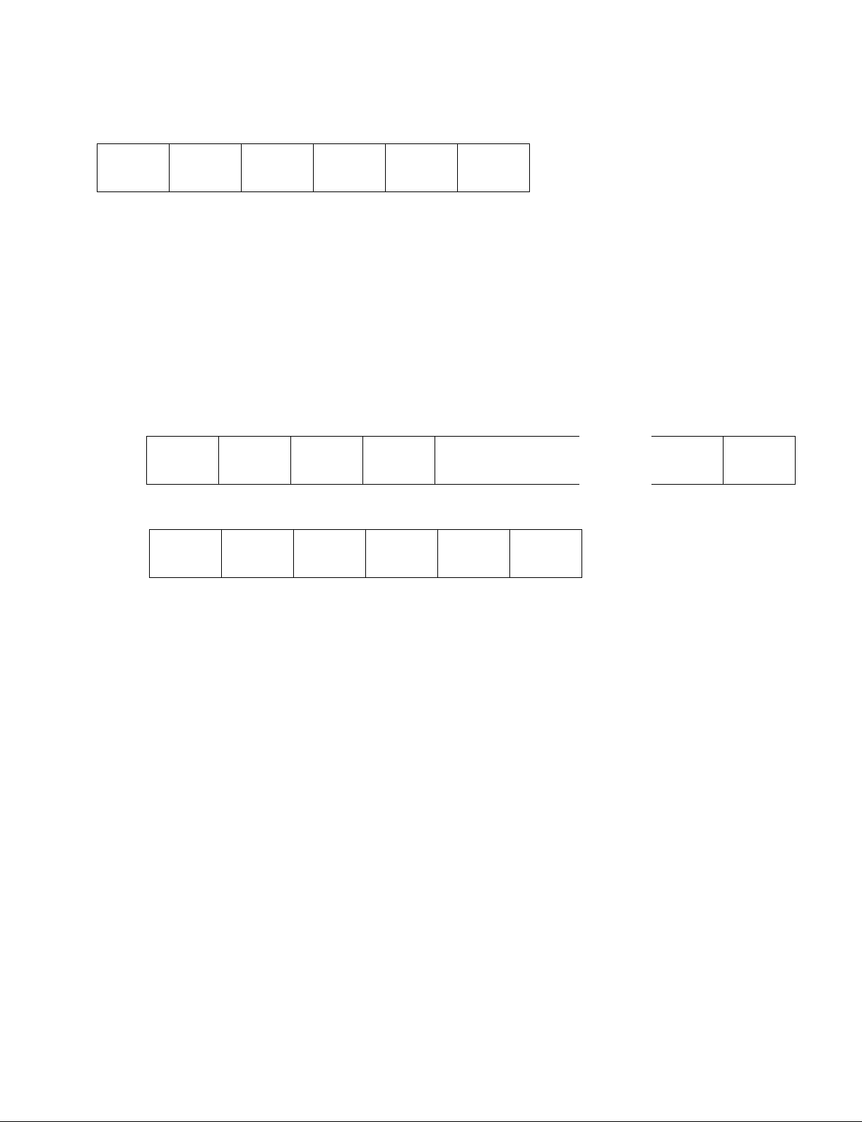
The communication between the CONTROLLER and the DEVICE is composed of CMD-1 + DATA
COUNT, CMD-2 + DATA and CHECKSUM, and is transmitted from CMD-1 + DATA COUNT in
order.
When the DATA COUNT is zero, the DATA is not transmitted.
When it is not zero, the DATA corresponded with the value is inserted between CMD-2 and CHECKSUM.
The command block can be illustrated as shown.
MSD LSD
CMD-1 CMD-2 DATA-1 CHECKSUM
DATA
COUNT
1 BYTE 1 BYTE 1 BYTE 1 BYTE 1 BYTE
DATA-n
(MAX.15)
CMD-1 : CMD-1 classifies the command into the main groups which indicates the function and direction
of the data words to follow.
Contents of CMD-1
CMD-1 Function
0 SYSTEM CONTROL
1 SYSTEM CONTROL RETURN
2 TRANSPORT CONTROL
4 PRESET & SELECT CONTROL
6 SENSE REQUEST
7 SENSE RETURN
Controller Device
Direction
DATA COUNT : DATA COUNT indicates the number of data bytes that are added to the
command. (0 to FH)
CMD-2 : Specifies the respective commands.
DATA : The number of data bytes and their contents are defined by the respective
commands.
CHECKSUM : The CHECKSUM is the lower eight value of the sum of the data bytes from
the first byte to the last byte immediately before CHECKSUM. It is used to
check the errors that are incurred by the data communication.
2
DSR Series
0x31
^^^^
CMD1 CMD20xFF
BYTE1 BYTE254
CSDATA
BYTE0
......
3-2. DSR-DR1000/A DISK Command
ID CMD1 CMD2DC CSDATA
1byte 1byte 1byte 1byte 0 to 255byte 1byte
a. ID : Code undefined as CMD1 of Sony VTR 9PIN PROTOCOL.
0x30 and 0x31 are designated as an ID of the extension command for DISK.
ID:0x30 : Indicates that it is a single block with less than 256-byte DATA length. Or it indicates
that it is the last block when transmitting a command by dividing into multiple blocks.
ID:0x31 : Indicates that there is a continuous block when transmitting a command by dividing it
into multiple blocks.
Example: When transmitting a command with data consisting of 256-byte DATA length
First block
Second block
0x30
^^^^
CMD1 CMD20xFF CSDATA
b. DC : Number of bytes of DATA (0 to 255)
BYTE255
DSR Series
3

c. CMD1: Specifies the categories of commands.
Contents of CMD-1
CMD1 FUNCTION DIRECTION
0x00 VTR SYSTEM CONTROL T → R
0x01 VTR SYSTEM CONTROL RETURN T ← R
0x02 VTR TRANSPORT CONTROL T → R
0x04 VTR PRESET & SELECT CONTROL T → R
0x06 VTR SENSE REQUEST T → R
0x07 VTR SENSE RETURN T ← R
0x10 SYSTEM PRESET T → R
0x11 SYSTEM STATUS SENSE T → R
0x12 SYSTEM STATUS T ← R
0x13 DRIVE CONTROL/PRESET T → R
0x14 DRIVE STATUS SENSE T → R
0x15 DRIVE STATUS T ← R
0x16 PORT CONTROL/PRESET T → R
0x17 PORT STATUS SENSE T → R
0x18 PORT STATUS T ← R
0x19 FILE CONTROL/PRESET T → R
0x1A FILE STATUS SENSE T → R
0x1B FILE STATUS T ← R
0xFx DEVICE DEPENDENT COMMAND T → R
T ← R
T:CONTROLLING DEVICE
R:CONTROLLED DEVICE
4
DSR Series

[System related commands]
0x00 to 0x07 are the ones that the upper four bits of CMD1 of the Sony VTR 9PIN PROTOCOL is
shifted to four bits rightward. The content is the same as that of the Sony VTR 9PIN PROTOCOL.
0x10 to 0x12 are in a category related to parameter settings and requests unique to the device.
[Drive related commands]
0x13 to 0x15 are in a category related to controls or parameter settings and requests for the DISK DEVICE that the device has. Drive ID is added to all the commands in the category, and the drive ID
specifies a target DISK DEVICE.
[Port related commands]
0x16 to 0x18 are in a category related to controls or parameter settings and requests for the logical port
that the device has. Port ID is added to all the commands in the category, and the port ID specifies a
target port.
[File related commands]
0x19 to 0x1B are in a category related to controls or parameter settings and requests for the opened file.
File handle is added to all the commands in this category, and the file handle specifies a target file.
[Device dependent commands]
0xFx (0xF0 to 0xFF) is in a category that allows defining the commands that depends on the device.
However, some commands do not fall into these categories.
DSR Series
5

d. CMD2 : Assigns individual commands according to the following code category list.
. CMD2 code category list
CMD2 (0x00 to 0xFF)
|
+----- Operation related codes (0x00 to 0x7F)
| |
| +-----Basic operation, open operation (0x00 to 0x3F)
| |
| +-----AUTO/MACRO operation (0x40 to 0x5F)
| |
| +-----Machine, maintenance, and service related codes (0x60 to 0x6F)
| |
| +-----Other, special operation (0x70 to 0x7F)
+----- Preset related codes (0x80 to 0xFF)
|
+-----FILE related codes (0x80 to 0x8F)
|
+-----AUTO/MACRO MODE setting (0x90 to 0x9F)
|
+-----VIDEO related codes (0xA0 to 0xAF)
|
+-----AUDIO related codes (0xB0 to 0xBF)
|
+-----TC related codes (0xC0 to 0xCF)
|
+----- System parameter setting (0xD0 to 0xDF)
|
+----- Maintenance and service related codes (0xE0 to 0xEF)
|
+-----Other, special mode setting (0xF0 to 0xFF)
Individual codes are categorized as follows according to whether they are odd and even:
However, some codes do not fall into these categories depending on the content of commands.
Even (LSB=0) **** OFF, playback Odd (LSB=1) **** ON, recording
e. DATA : Additional data of individual commands (total of 255 bytes at maximum).
f. CS (CHECKSUM) : CS is the lower eight value of the sum of the data bytes from the first byte (ID) to
the last byte immediately before CS.
6
DSR Series
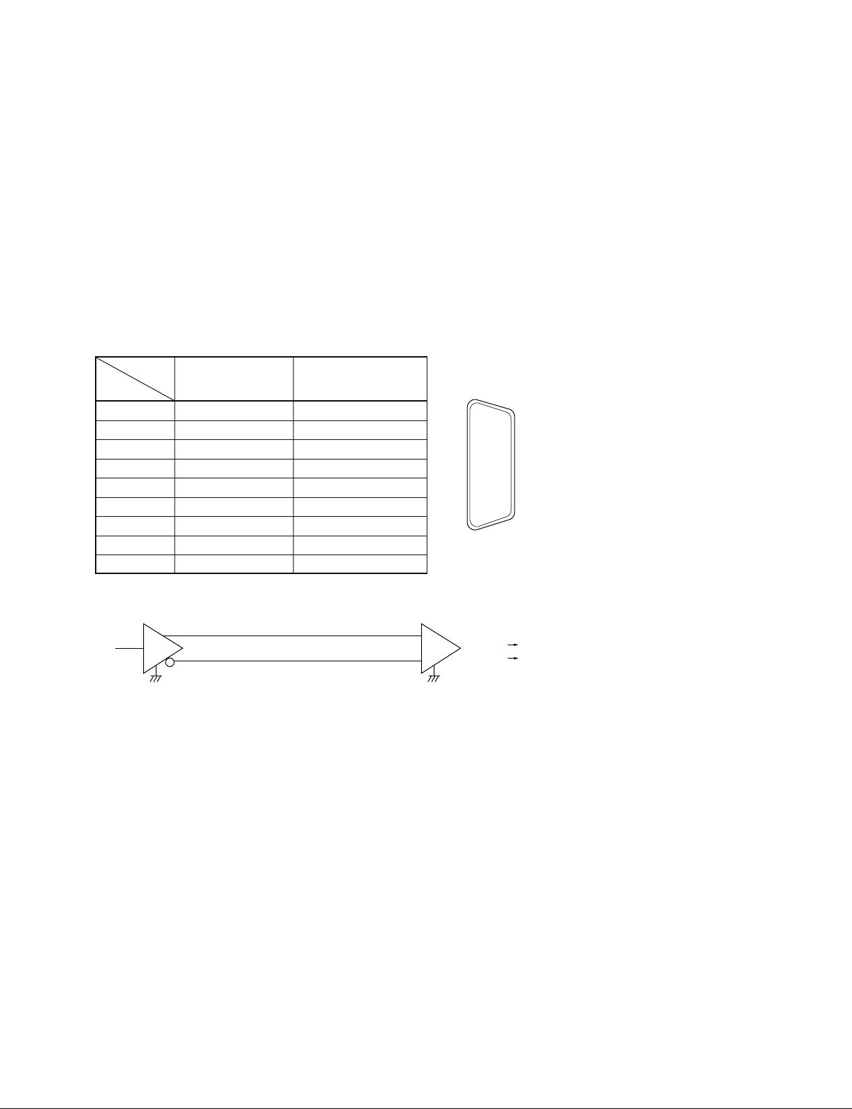
4. Connector Pin Assignment
Interface connector : 9 pin D-subminiature female (D-9S)
The pin assignment for the CONTROLLER and the DEVICE is as shown in the following table.
Among the DSR series VTRs, the VTRs (DSR-85/85P) that have the built-in CONTROLLER function,
obtain the following CONTROLLER pin assignment when they execute the QSDI dubbing and also
when the RECORDER lamp or the PLAYER lamp turns on the control panel.
Except for that, it’s become pin assignment of DEVICE.
The VTR not had the function as CONTROLLER (DSR-60/60P) is always become pin assignment of
DEVICE.
Signal
Pin
1 Frame Ground Frame Ground
2 Receive A Transmit A
3 Transmit B Receive B
4 Transmit Common Receive Common
5 Spare Spare
6 Receive Common Transmit Common
7 Receive B Transmit B
8 Transmit A Receive A
9 Frame Ground Frame Ground
Controller Device
A and B are defined as shown below.
B
T R
T : Transmit R : Receive
A
+
_
1
6
2
7
3
8
4
9
5
External view
A < B “1” (MARK)
A > B “0” (SPACE)
DSR Series
7

5. Communication Protocol
1) All communication between the CONTROLLER and the DEVICE will be under the direct supervision of the CONTROLLER.
When the DEVICE receives the COMMAND sent from CONTROLLER, the following COMMAND
is returned.
. In the case that the DEVICE receives the COMMAND not required the data
..................... ACK
. In the case that the DEVICE receives the COMMAND required the data
..................... COMMAND + DATA
. In the case that the error communication is detected or the undefined COMMAND is received
..................... NAK + ERROR DATA
2) The CONTROLLER is not transmit additional COMMAND blocks to a DEVICE prior to receivers
an appropriate response to a previous COMMAND block.
3) The CONTROLLER is not interrupt transmission of a byte in a COMMAND block for more than 10
ms. A DEVICE detecting an interruption of a byte in a COMMAND block that exceeds 10 ms.
CONTROLLER execute a TIME-OUT error sequence.
A DEVICE will void the receiving COMMAND block and transmit a NAK (TIME OUT).
4) The DEVICE, following receipt of a COMMAND block from the CONTROLLER will transmit a
response within 9 ms.
Therefore if the CONTROLLER cannot receive the appropriate response from the DEVICE within
10 ms. After performing the COMMAND block transmission, it will execute as the communication
is not performed under the normal condition, and it will process as necessary.
5) The DEVICE, upon detection of an error, it will immediately transmit a NAK to the CONTROLLER.
(The contents of an error is shown on the COMMAND tables.)
The CONTROLLER, upon receipt of NAK, it will immediately stop transmission of the COMMAND block. The DEVICE, following transmission of NAK, it will receive a subsequent COMMAND block within 10 ms. (except NAK UNDEFINED COMMAND) and will process as necessary.
8
DSR Series

6. Command
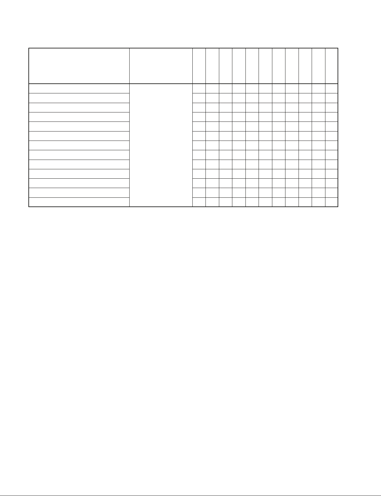
The marks shown in the tables mean the following contents.
1) O marked COMMAND’s model can correspond. If the contents are in the RETURN column,
RETURN + DATA will be returned.
If the contents are not in the RETURN column, “10.01 : ACK” will be returned.
2) T marked COMMAND returns ACK as RETURN, but does not operate.
3) X marked COMMAND does not correspond and returns “11.12.01 : NAK UNDEFINED
COMMAND.
4) For details of the commands for disk recorders such as DSR-DR1000/A, refer to Section 6-2. Command Table (for Disk Recorder).
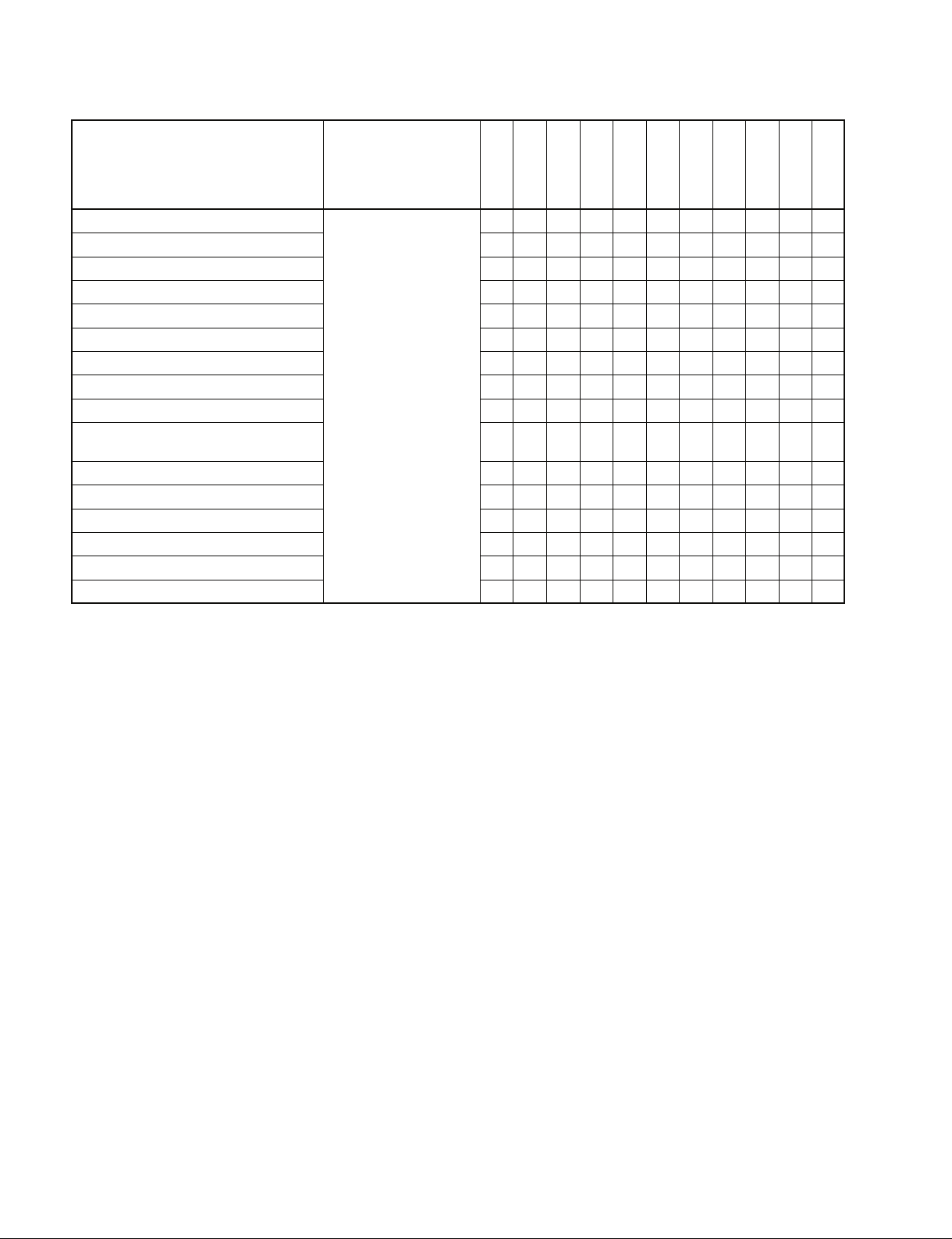
6-1. Command Table (for Cassette Recorder/Player)
Command
00.0C : LOCAL DISABLE
00.11 : DEVICE TYPE REQUEST
00.1D : LOCAL ENABLE
20.00 : STOP
20.01 : PLAY
20.02 : REC
20.04 : STANDBY OFF
20.05 : STANDBY ON
20.0D : DMC START
20.0F : EJECT
20.10 : FAST FWD
2X.11 : JOG FWD
2X.12 : VAR FWD
2X.13 : SHUTTLE FWD
20.20 : REWIND
2X.21 : JOG REV
2X.22 : VAR REV
2X.23 : SHUTTLE REV
20.30 : PREROLL
24.31 : CUE UP WITH DATA
24.32 : SYNC POINT PREROLL
24.34 : SYNC PLAY
21.38 : PROGRAM PLAY +
21.39 : PROGRAM PLAY _
20.3C : DMC PREROLL
20.40 : PREVIEW
20.41 : REVIEW
Return
O → ACK
X → NAK
12.11 : DEVICE TYPE
O → ACK
X → NAK
O/T → ACK
X → NAK
HVR-1500/A
(DVCAM)
HVR-1500
(HDV)
HVR-1500A
(HDV)
DSR-2000/A
DSR-1800/A
DSR-1600/A
DSR-1500/A
DSR-85/80
DSR-70A
DSR-70
DSR-60
OOOOOOOOOOO
OOOOOOOOOOO
OOOOOOOOOOO
OOOOOOOOOOO
OOOOOOOOOOO
OOOOOTOOOOT
OOOOOOOOOOO
OOOOOOOOOOO
XXXOXXXXOXX
OOOOOOOOOOO
OOOOOOOOOOO
OOOOOOOOOOO
OOOOOOOOOOO
OOOOOOOOOOO
OOOOOOOOOOO
OOOOOOOOOOO
OOOOOOOOOOO
OOOOOOOOOOO
OOOOOOOOOOO
OOOOOOOOOOO
OOOOOOOOOOO
OOOOOOOOOOO
XXXOXXXXOXX
XXXOXXXXOXX
XXXOXXXXOXX
OTTOOTOOOOT
OTTOOTOOOOT
DSR Series
9
Command
20.42 : AUTO EDIT
20.4B : DMC RUN
20.4C : DMC PREVIEW
20.52 : TENSION RELEASE
20.54 :
ANTI-CLOG TIMER DISABLE
20.55 : ANTI-CLOG TIMER ENABLE
2X.5C: DMC SET FWD
2X.5D: DMC SET REV
20.60 : FULL EE OFF
20.61 : FULL EE ON
20.63 : SELECT EE ON
20.64 : EDIT OFF
20.65 : EDIT ON
Return
O/T → ACK
X → NAK
HVR-1500/A
(DVCAM)
HVR-1500
(HDV)
HVR-1500A
(HDV)
DSR-2000/A
DSR-1800/A
DSR-1600/A
DSR-1500/A
DSR-85/80
DSR-70A
DSR-70
DSR-60
OTTOOTOOOOT
XXXOXXXXOXX
XXXOXXXXOXX
OOOOOOOOOOO
OOOOOOOOOOO
OOOOOOOOOOO
XXXOXXXXOXX
XXXOXXXXOXX
OOOOOTOOOOT
OOOOOTOOOOT
OTTOOTOOOOT
OTTOOTOOOOT
OTTOOTOOOOT
10
DSR Series

Command
44.00 : TIMER-1 PRESET
44.04 : TIME CODE PRESET
4X.05 : USER’S BIT PRESET
40.08 : TIMER-1 RESET
40.10 : IN ENTRY
40.11 : OUT ENTRY
40.12 : A IN ENTRY
40.13 : A OUT ENTRY
44.14 : IN DATA PRESET
44.15 : OUT DATA PRESET
44.16 : A IN DATA PRESET
44.17 : A OUT DATA PRESET
40.18 : IN SHIFT +
40.19 : IN SHIFT _
40.1A : OUT SHIFT +
40.1B : OUT SHIFT _
40.1C : A IN SHIFT +
40.1D : A IN SHIFT _
40.1E : A OUT SHIFT +
40.1F : A OUT SHIFT _
40.20 : IN RESET
40.21 : OUT RESET
40.22 : A IN RESET
40.23 : A OUT RESET
40.24 : IN RECALL
40.25 : OUT RECALL
40.26 : A IN RECALL
40.27 : A OUT RECALL
40.2D : LOST LOCK RESET
4X.30 : EDIT PRESET
44.31 : PREROLL TIME PRESET
41.32 : TAPE/AUTO SELECT
41.36 : TIMER MODE SELECT
41.37 : INPUT CHECK
41.3D : PREREAD MODE SELECT
43.3F : Δ t REC/PLAY PRESET
40.40 : AUTO MODE OFF
40.41 : AUTO MODE ON
40.44 : AUDIO SPLIT OFF
40.45 : AUDIO SPLIT ON
Return
O/T → ACK
X → NAK
HVR-1500/A
(DVCAM)
HVR-1500
(HDV)
HVR-1500A
(HDV)
DSR-2000/A
DSR-1800/A
DSR-1600/A
DSR-1500/A
DSR-85/80
DSR-70A
DSR-70
DSR-60
OOOOOOOOOOO
OOOOOTOOOOT
OOOOOTOOOOT
OOOOOOOOOOO
OOOOOOOOOOO
OOOOOOOOOOO
OOOOOOOOOOO
OOOOOOOOOOO
OOOOOOOOOOO
OOOOOOOOOOO
OOOOOOOOOOO
OOOOOOOOOOO
OOOOOOOOOOO
OOOOOOOOOOO
OOOOOOOOOOO
OOOOOOOOOOO
OOOOOOOOOOO
OOOOOOOOOOO
OOOOOOOOOOO
OOOOOOOOOOO
OOOOOOOOOOO
OOOOOOOOOOO
OOOOOOOOOOO
OOOOOOOOOOO
OOOOOOOOOOO
OOOOOOOOOOO
OOOOOOOOOOO
OOOOOOOOOOO
OOOOOOOOOOO
OTTOOTOOOOT
OOOOOOOOOOO
OOOOOTOOOOT
OOOOOOOOOOO
OOOOOTOOOOT
XXXOXXXXOXX
TTTTTTT
OOOOOOOOOOO
OOOOOOOOOOO
OTTOOOOOOOO
OTTOOOOOOOO
85 : O
OTT
80 : T
DSR Series
11
Command
40.46 : VARIABLE MEMORY OFF
40.47 : VARIABLE MEMORY ON
42.50 : DA INPUT SELECT
4X.54 : EXTENDED DA INPUT SELECT
41.58 : DA SAMPLING FREQ PRESET
41.60 : VITC BYPASS
42.61 : TCG MODE SELECT
42.70 : VIDEO INPUT SELECT
41.9E : SUPERIMPOSE
4X.AE: AUDIO MONITOR CHANNEL
SELECT
40.C0 : TIMELINE STOP
40.C1 : TIMELINE RUN
44.C3 : TIMELINE PRESET
4X.C4: DEFINE EVENT
42.C5 : CLEAR EVENT
41.CB : BREAK
Return
O/T → ACK
X → NAK
HVR-1500/A
(DVCAM)
HVR-1500
(HDV)
HVR-1500A
(HDV)
DSR-2000/A
DSR-1800/A
DSR-1600/A
DSR-1500/A
DSR-85/80
DSR-70A
DSR-70
DSR-60
XXXOXXXXTXX
XXXOXXXXTXX
OOOOOTOOOOT
OOOOOTOOOOT
OTTOOTOOOOT
OTTOOTOXOXX
OOOOOTOOOOT
OOTOOTOOOOT
OOOOOOOOOOO
OOOOOOOXOXX
OOOOOOOOOOO
OOOOOOOOOOO
OOOOOOOOOOO
OOOOOOOOOOO
OOOOOOOOOOO
OOOOOOOOOOO
12
DSR Series
Command
61.0A : TC GEN DATA
SENSE
61.0C : CURRENT TIME
SENSE
60.10 : IN DATA SENSE
60.11 : OUT DATA SENSE
60.12 : A IN DATA SENSE
60.13 : A OUT DATA SENSE
60.20 : STATUS SENSE
60.2E : COMMAND SPEED
SENSE
60.2F : VAR MEM SPEED
SENSE
6X.30 : EDIT PRESET SENSE
60.31 : PREROLL TIME
SENSE
60.32 : TAPE/AUTO SENSE
60.36 : TIMER MODE SENSE
60.3F : Δ t REC/PLAY
PRESET SENSE
60.50 : DA INPUT SENSE
6X.54 : EXTENDED DA INPUT
SENSE
60.58 : DA SAMPLING FREQ
SENSE
60.60 : VITC BYPASS SENSE
60.61 : TCG MODE SENSE
Return
74.08 : GEN TIME DATA
74.09 : GEN UB DATA
78.08 : GEN TC & UB DATA
74.00 : TIMER-1 DATA
74.01 : TIMER-2 DATA
74.04 : LTC TIME DATA
78.04 : LTC TIME & UB DATA
74.05 : LTC UB DATA
74.06 : VITC TIME DATA
78.06 :
74.07 : VITC UB DATA
74.14 : LTC INTERPOLATED
78.14 : LTC INTERPOLATED
74.16 :
78.16 : VITC HOLD TIME &
70.0D : REQUEST TIME
74.10 : IN DATA
74.11 : OUT DATA
74.12 : A IN DATA
74.13 : A OUT DATA
7X.20 : STATUS DATA
71.2E : COMMAND SPEED
71.2F : VAR MEM SPEED
7X.30 : EDIT PRESET DATA
74.31 : PREROLL TIME
71.32 : TAPE/AUTO STATUS
71.36 : TIMER MODE DATA
73.3F : Δ t REC/PLAY\
71.50 : DA INPUT STATUS
7X.54 : EXTENDED DA
71.58 : DA SAMPLING FREQ
71.60 :
72.61 : TCG MODE
VITC TIME & UB DATA
TIME DATA
TIME & UB DATA
VITC HOLD TIME DATA
UB DATA
DATA MISSING
DATA
DATA
DATA
DATA
PRESET DATA
INPUT STATUS
STATUS
VITC BYPASS STATUS
HVR-1500/A
(DVCAM)
HVR-1500
(HDV)
HVR-1500A
(HDV)
DSR-2000/A
DSR-1800/A
DSR-1600/A
DSR-1500/A
DSR-85/80
DSR-70A
DSR-70
DSR-60
OOOOOXOOOOX
OOOOOXOOOOX
OOOOOXOOOOX
OOOOOOOOOOO
OOOOOOOOOOO
OOOOOOOOOOO
OOOOOOOOOOO
OOOOOOOOOOO
OXXOOOOXOXX
OXXOOOOXOXX
OXXOOOOXOXX
OOOOOOOOOOO
OOOOOOOOOOO
OXXOOOOXOXX
OXXOOOOXOXX
OOOOOOOOOOO
OOOOOOOOOOO
OOOOOOOOOOO
OOOOOOOOOOO
OOOOOOOOOOO
OOOOOOOOOOO
OOOOOOOOOOO
XXXOXXXXOXX
OOOOOOOOOOO
OOOOOOOOOOO
OOOOOOOOOOO
OOOOOOOOOOO
OOOOOOOOOOO
OOOOOXOOOOX
OOOOOXOOOOX
OOOOOXOOOOX
OOOOOOOXOXX
OOOOOXOOOOX
DSR Series
13
Command
60.70 : VIDEO INPUT SENSE
60.9E : SUPERIMPOSE
SENSE
60.AE : AUDIO MONITOR
60.C2 :
TIMELINE SOURCE
SENSE
60.C3 : TIMELINE TIME
SENSE
62.C4 : EVENT DATA SENSE
60.C6 :
TIMELINE STATUS
SENSE
61.C7 : EVENT QUEUE
SENSE
61.C8 : UNSUCCESSFUL
EVENT SENSE
Return
72.70 :
71.9E : SUPERIMPOSE
74.AE : AUDIO MONITOR
71.C2 : TIMELINE SOURCE
75.C3 : TIMELINE TIME
7X.C4 : EVENT DATA
75.C6 : TIMELINE STATUS
7X.C7 : EVENT QUEUE
7X.C8 : UNSUCCESSFUL
VIDEO INPUT STATUS
STATUS
CHANNEL STATUS
EVENT
HVR-1500/A
(DVCAM)
HVR-1500
(HDV)
HVR-1500A
(HDV)
DSR-2000/A
DSR-1800/A
DSR-1600/A
DSR-1500/A
DSR-85/80
DSR-70A
DSR-70
DSR-60
OOOOOXOOOOX
OOOOOOOOOOO
OOOOOOOXOXX
OOOOOOOOOOO
OOOOOOOOOOO
OOOOOOOOOOO
OOOOOOOOOOO
OOOOOOOOOOO
OOOOOOOOOOO
14
DSR Series

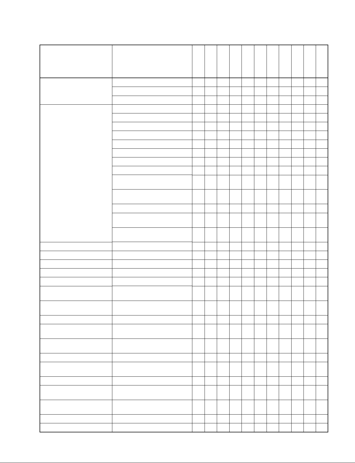
6-2. Command Table (for Disk Recorder)
“IN (R)” of DSR-DR1000/A indicates the RECORDER side during the simultaneous record/playback
(REMOTE I/F of INTERFACE SELECT is set to “9PIN (DUAL))”.
In the same way, “OUT (P)” of DSR-DR1000/A indicates the PLAYER side.
n
The IN points and the OUT points of the program playback that are set using the “← (IN)” or “→ (OUT)” of the
front panel are different from the IN points and the OUT points that are set from the 9-pin remote control unit.
When the IN DATA SENSE command and the OUT DATA SENSE command that are issued from the 9-pin
remote control unit are sent to the DSR-DR1000/A, the IN points and the OUT points that are by this operation will not be returned.
Command
00.0C : LOCAL DISABLE
00.11 : DEVICE TYPE REQUEST
00.1D : LOCAL ENABLE
20.00 : STOP
20.01 : PLAY
20.02 : REC
20.04 : STANDBY OFF
20.05 : STANDBY ON
20.0D : DMC START
20.0F : EJECT
20.10 : FAST FWD
2X.11 : JOG FWD
2X.12 : VAR FWD
2X.13 : SHUTTLE FWD
20.20 : REWIND
2X.21 : JOG REV
2X.22 : VAR REV
2X.23 : SHUTTLE REV
20.30 : PREROLL
24.31 : CUE UP WITH DATA
24.32 : SYNC POINT PREROLL
24.34 : SYNC PLAY
21.38 : PROGRAM PLAY +
21.39 : PROGRAM PLAY _
20.3C : DMC PREROLL
20.40 : PREVIEW
20.41 : REVIEW
20.42 : AUTO EDIT
20.4B : DMC RUN
20.4C : DMC PREVIEW
20.52 : TENSION RELEASE
20.54 :
ANTI-CLOG TIMER DISABLE
*1 : Both of the RECORDER and the PLAYER side can be set to Disable independently.
DSR Series
O → ACK
X → NAK
12.11 : DEVICE TYPE
O → ACK
X → NAK
O/T → ACK
X → NAK
Return
DSR-DR1000/A DSR-DR1000/A DSR-DR1000/A
IN (R) OUT (P)
OO*1O
OOO
OOO
OOO
OTO
OOT
OOO
OOO
OTO
TTT
OTO
OTO
OTO
OTO
OTO
OTO
OTO
OTO
OTO
OTO
OTO
OTO
OTO
OTO
OTO
TTT
TTT
TTT
OTO
OTO
OOO
TTT
*1
15
Command
Return
DSR-DR1000/A DSR-DR1000/A DSR-DR1000/A
IN (R) OUT (P)
20.55 : ANTI-CLOG TIMER ENABLE
2X.5C: DMC SET FWD
2X.5D: DMC SET REV
20.60 : FULL EE OFF
20.61 : FULL EE ON
O/T → ACK
X → NAK
20.63 : SELECT EE ON
20.64 : EDIT OFF
20.65 : EDIT ON
*2 : When both of the R and P indicators of the LINE OUT SELECT on the front panel light, output can be selected from the (P) side port.
TTT
OTO
OTO
OTO
OTO
TTO
TTT
TTT
*2
*2
*2
16
DSR Series
Command
44.00 : TIMER-1 PRESET
44.04 : TIME CODE PRESET
4X.05 : USER’S BIT PRESET
40.08 : TIMER-1 RESET
40.10 : IN ENTRY
40.11 : OUT ENTRY
40.12 : A IN ENTRY
40.13 : A OUT ENTRY
44.14 : IN DATA PRESET
44.15 : OUT DATA PRESET
44.16 : A IN DATA PRESET
44.17 : A OUT DATA PRESET
40.18 : IN SHIFT +
40.19 : IN SHIFT _
40.1A : OUT SHIFT +
40.1B : OUT SHIFT _
40.1C : A IN SHIFT +
40.1D : A IN SHIFT _
40.1E : A OUT SHIFT +
40.1F : A OUT SHIFT _
40.20 : IN RESET
40.21 : OUT RESET
40.22 : A IN RESET
40.23 : A OUT RESET
40.24 : IN RECALL
40.25 : OUT RECALL
40.26 : A IN RECALL
40.27 : A OUT RECALL
40.2D : LOST LOCK RESET
4X.30 : EDIT PRESET
44.31 : PREROLL TIME PRESET
41.32 : TAPE/AUTO SELECT
41.33 : SERVO REFERENCE SELECT
41.36 : TIMER MODE SELECT
41.37 : INPUT CHECK
41.3D : PREREAD MODE SELECT
43.3F : Δ t REC/PLAY PRESET
40.40 : AUTO MODE OFF
40.41 : AUTO MODE ON
40.44 : AUDIO SPLIT OFF
Return
O/T → ACK
X → NAK
DSR-DR1000/A DSR-DR1000/A DSR-DR1000/A
IN (R) OUT (P)
OO*3O
*3
OOT
OOT
OO*3O
OO*4O
OO*4O
OO*4O
OO*4O
OO*4O
OO*4O
OO*4O
OO*4O
OO*4O
OO*4O
OO*4O
OO*4O
OO*4O
OO*4O
OO*4O
OO*4O
OO*4O
OO*4O
OO*4O
OO*4O
OO*4O
OO*4O
OO*4O
OO*4O
*3
*4
*4
*4
*4
*4
*4
*4
*4
*4
*4
*4
*4
*4
*4
*4
*4
*4
*4
*4
*4
*4
*4
*4
*4
OOO
TTT
OO*3O
*3
OOO
TTT
OOO
OT*5T
*5
XXX
TTT
OOO
OOO
OOO
*3 : The (R) side and the (P) side can be set to PRESET independently.
*4 : The (P) side can be set to the same setting as in the ordinary VTR. It jumps to these points at the event of Preroll.
The (R) side can only save the set data, and cannot perform the Preroll operation. It returns the set data to SENSE.
*5 : When both of the R and P indicators of the LINE OUT SELECT on the front panel light, the forced EE mode can be set from the (P) side.
DSR Series
17
Command
40.45 : AUDIO SPLIT ON
40.46 : VARIABLE MEMORY OFF
40.47 : VARIABLE MEMORY ON
42.50 : DA INPUT SELECT
4X.54 : EXTENDED DA INPUT SELECT
41.58 : DA SAMPLING FREQ PRESET
41.60 : VITC BYPASS
42.61 : TCG MODE SELECT
42.70 : VIDEO INPUT SELECT
41.9E : SUPERIMPOSE
4X.AE: AUDIO MONITOR CHANNEL
SELECT
40.C0 : TIMELINE STOP
40.C1 : TIMELINE RUN
44.C3 : TIMELINE PRESET
4X.C4: DEFINE EVENT
42.C5 : CLEAR EVENT
41.CB : BREAK
Return
O/T → ACK
X → NAK
DSR-DR1000/A DSR-DR1000/A DSR-DR1000/A
IN (R) OUT (P)
OOO
OTT
OTT
OOO
OOO
OOO
OOO
OOO
OOO
OOO
OOO
OOO
OOO
OOO
OOO
OOO
OOO
18
DSR Series
Command
61.0A : TC GEN DATA
SENSE
61.0C : CURRENT TIME
SENSE
60.10 : IN DATA SENSE
60.11 : OUT DATA SENSE
60.12 : A IN DATA SENSE
60.13 : A OUT DATA SENSE
60.20 : STATUS SENSE
60.2E : COMMAND SPEED
SENSE
60.2F : VAR MEM SPEED
SENSE
6X.30 : EDIT PRESET SENSE
60.31 : PREROLL TIME
SENSE
60.32 : TAPE/AUTO SENSE
60.36 : TIMER MODE SENSE
60.3F : Δ t REC/PLAY
PRESET SENSE
60.50 : DA INPUT SENSE
6X.54 : EXTENDED DA INPUT
SENSE
60.58 : DA SAMPLING FREQ
SENSE
60.60 : VITC BYPASS SENSE
60.61 : TCG MODE SENSE
Return
74.08 : GEN TIME DATA
74.09 : GEN UB DATA
78.08 : GEN TC & UB DATA
74.00 : TIMER-1 DATA
74.01 : TIMER-2 DATA
74.04 : LTC TIME DATA
78.04 : LTC TIME & UB DATA
74.05 : LTC UB DATA
74.06 : VITC TIME DATA
78.06 :
VITC TIME & UB DATA
74.07 : VITC UB DATA
74.14 : LTC INTERPOLATED
TIME DATA
78.14 : LTC INTERPOLATED
TIME & UB DATA
74.16 :
VITC HOLD TIME DATA
78.16 : VITC HOLD TIME &
UB DATA
70.0D : REQUEST TIME
DATA MISSING
74.10 : IN DATA
74.11 : OUT DATA
74.12 : A IN DATA
74.13 : A OUT DATA
7X.20 : STATUS DATA
71.2E : COMMAND SPEED
DATA
71.2F : VAR MEM SPEED
DATA
7X.30 : EDIT PRESET DATA
74.31 : PREROLL TIME
DATA
71.32 : TAPE/AUTO STATUS
DATA
71.36 : TIMER MODE DATA
73.3F : Δ t REC/PLAY\
PRESET DATA
71.50 : DA INPUT STATUS
7X.54 : EXTENDED DA
INPUT STATUS
71.58 : DA SAMPLING FREQ
STATUS
71.60 :
VITC BYPASS STATUS
72.61 : TCG MODE
DSR-DR1000/A DSR-DR1000/A DSR-DR1000/A
IN (R) OUT (P)
OOO
OOO
OOO
OO*6O
OO*6O
OO*6O
OO*6O
OO*6O
OO*6O
OO*6O
OO*6O
OO*6O
OO*6O
OO*6O
OO*6O
OO*6O
*6
*6
*6
*6
*6
*6
*6
*6
*6
*6
*6
*6
*6
OOO
OOO
OOO
OOO
OOO
OO*6O
*6
OOO
OOO
OOO
OOO
OOO
OOO
OOO
OOO
OOO
OOO
OOO
*6 : The respective values of the (R) side and the (P) side are returned respectively.
DSR Series
19
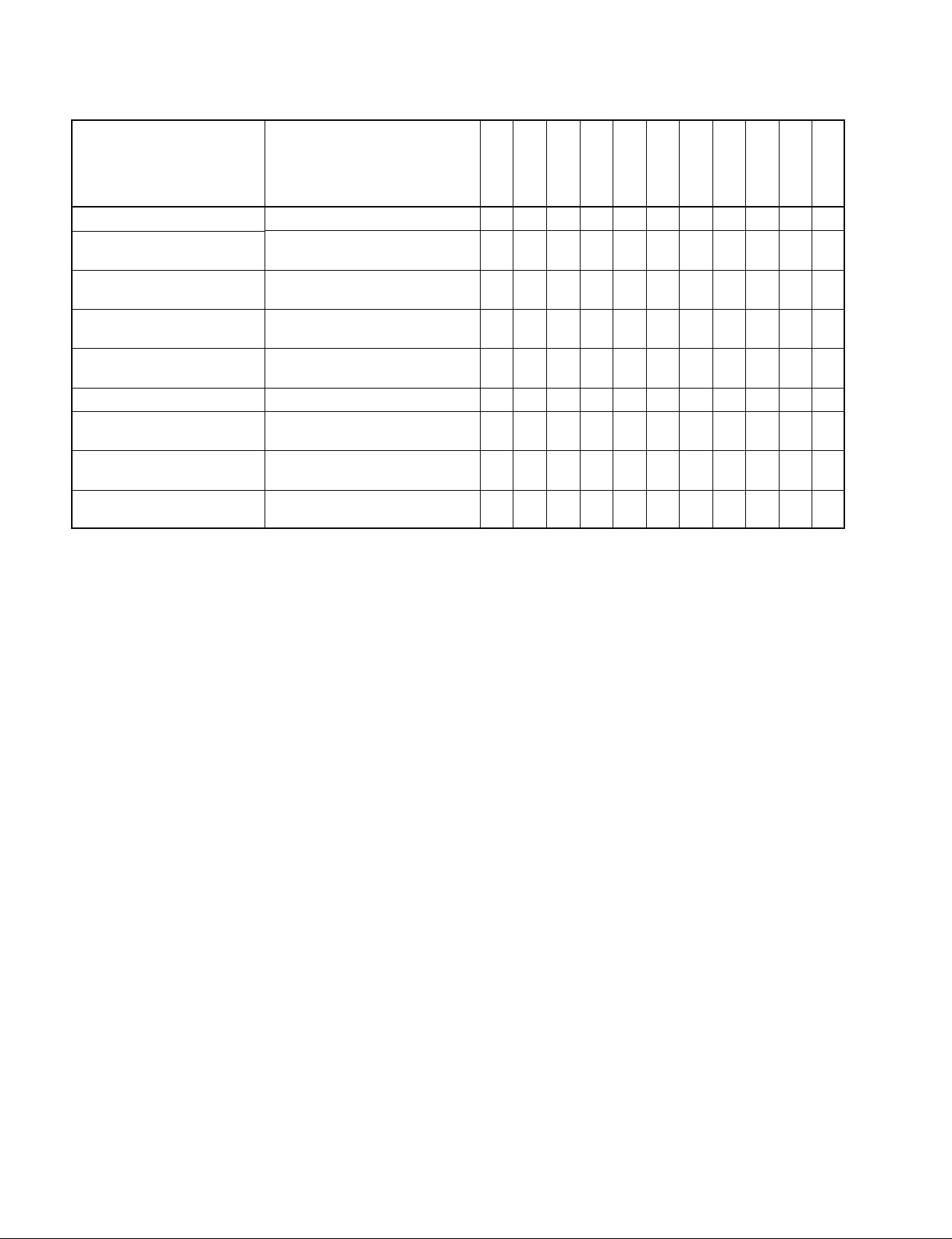
Command
60.70 : VIDEO INPUT SENSE
60.9E : SUPERIMPOSE
SENSE
60.AE : AUDIO MONITOR
60.C2 :
TIMELINE SOURCE
SENSE
60.C3 : TIMELINE TIME
SENSE
62.C4 : EVENT DATA SENSE
60.C6 :
TIMELINE STATUS
SENSE
61.C7 : EVENT QUEUE
SENSE
61.C8 : UNSUCCESSFUL
EVENT SENSE
72.70 :
71.9E : SUPERIMPOSE
74.AE : AUDIO MONITOR
71.C2 : TIMELINE SOURCE
75.C3 : TIMELINE TIME
7X.C4 : EVENT DATA
75.C6 : TIMELINE STATUS
7X.C7 : EVENT QUEUE
7X.C8 : UNSUCCESSFUL
Return
VIDEO INPUT STATUS
STATUS
CHANNEL STATUS
EVENT
DSR-DR1000/A DSR-DR1000/A DSR-DR1000/A
OOO
OOO
OOO
OOO
OOO
OOO
OOO
OOO
OOO
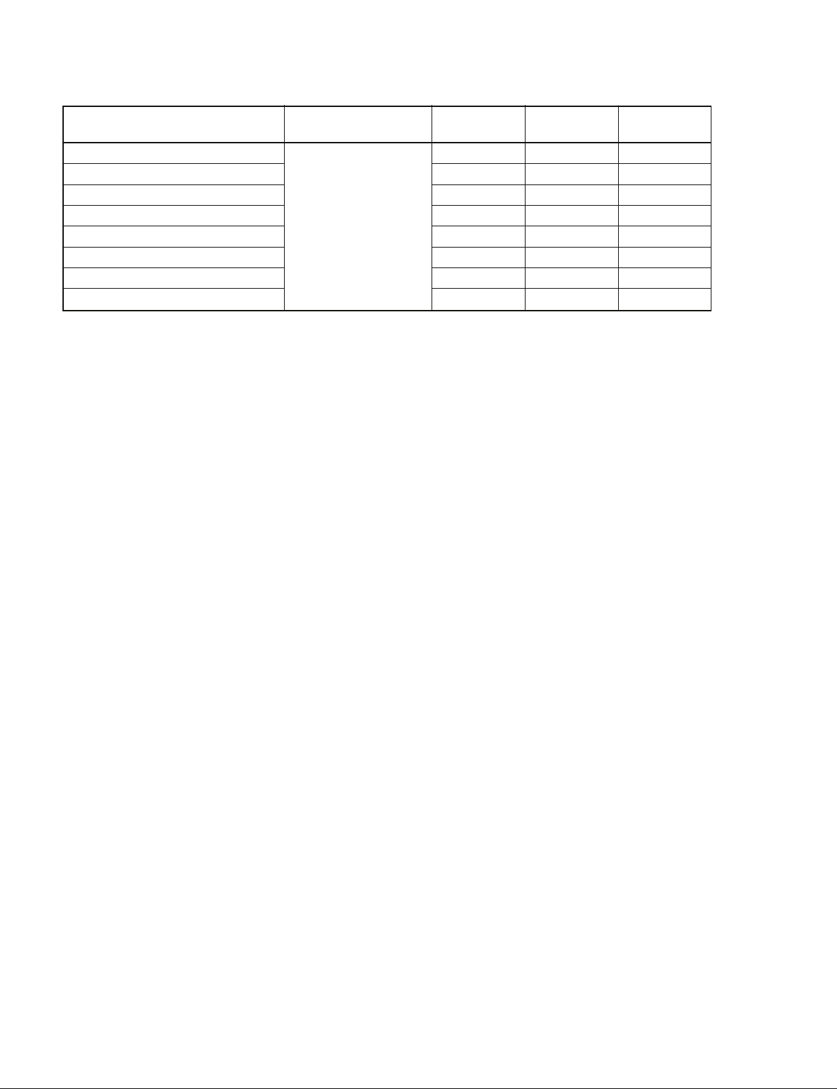
6-3. Command Table (for DSR-DR1000/A Disk Command)
COMMAND RETURN
DC C1 C2 D1
System Command
00 10 40
XX 10 41
00 10 42
00 10 43
04 11 D0
Drive Command
XX 13 03
0X 14 81
03 14 D0
Port Command
XX 16 00
01 17 00
File Command
01 19 01
03 1A 82
02 1A C0
VFL DOWNLOAD ENABLE
VFL DOWNLOAD DATA SET
VFL DOWNLOAD DATA WRITE
VFL DOWNLOAD DATA CLEAR
SYSTEM STATUS SENSE
DELETE
FILE SYSTEM DATA SENSE
DRIVE STATUS SENSE
OPEN PLAY
FILE OPEN STATUS SENSE
CLOSE
FILE ENTRY DATA SENSE
CURRENT TIME SENSE
IN (R) OUT (P)
DC C1 C2 D1
10 01
10 01
10 01
10 01
XX 12 D0
10 01
XX 15 81
XX 15 D0
10 01
0X 18 00
10 01
XX 1B 82
XX 1B C0
Both DSR-DR1000/A IN (R) and DSR-DR1000/A OUT (P) have the same function (receiving the same command).
20
DSR Series
7. Protocol Command
7-1. VTR Command
00.0C : LOCAL DISABLE
When receiving this command, all functions of the DEVICE will be disabled.
00.11 : DEVICE TYPE REQUEST
12.11 : DEVICE TYPE
The “00.11 : DEVICE TYPE REQUEST” command is used to ask the model of the DEVICE to
be connected, and if the DEVICE receives this command, the “12.11 : DEVICE TYPE” with 2
bytes data will be sent back as a response.
Model DATA-1 DATA-2
DSR-2000/2000P/2000A/2000AP 8X 14
DSR-1800/1800P/1800A/1800AP 8X 15
DSR-1600/1600P/1600A/1600AP 8X 16
DSR-1500/1500P/1500A/1500AP 8X 17
DSR-DR1000/DR1000P/DR1000A/DR1000AP 8X 18
DSR-85/85P 8X 10
DSR-80/80P 8X 11
DSR-70A/70AP 8X 13
DSR-70/70P 8X 13
DSR-60/60P 8X 12
NTSC Model : X=0
PAL Model : X=1
00.1D : LOCAL ENABLE
When receiving this command, the control panel operation will be enabled according to the
DEVICE setting.
When the power of the DEVICE is turned on, it will be set to the LOCAL ENABLE state.
10.01 : ACK
When receiving this command, the DEVICE will send back this command as acknowledgement.
11.12 : NAK
When detecting the communication errors or receiving the undefined COMMAND, the
CONTROLLER will send back this command as not-acknowledgement.
BIT-7 to BIT-0 of DATA-1 will be set in accordance with the contents.
[DATA-1]
BIT-7 BIT-6 BIT-5 BIT-4 BIT-3 BIT-2 BIT-1 BIT-0
TIME OUT
FRAMING
ERROR
20.00 : STOP
20.01 : PLAY
20.02 : REC
20.04 : STANDBY OFF
20.05 : STANDBY ON
When receiving one of the above commands, the DEVICE will be in the specified mode.
The “20.04 : STANDBY OFF” command is available only when the DEVICE is in STOP mode.
OVERRUN
ERROR
PARITY
ERROR
CHECKSUM
ERROR
SOFTWARE
OVERRUN
UNDEFINED
COMMAND
DSR Series
21

20.0D : DMC START : DMC=Dynamic Motion Control (=VAR MEMORY)
This command is used to run the DEVICE from the present tape position at the speed that is
stored by the “20.4B : DMC RUN” command.
20.0F : EJECT
When receiving this command, the DEVICE ejects the cassette.
20.10 : FAST FWD
20.20 : REWIND
When receiving this command, the DEVICE will become the specified mode.
2X.11 : JOG FWD
2X.12 : VAR FWD
2X.13 : SHUTTLE FWD
2X.21 : JOG REV
2X.22 : VAR REV
2X.23 : SHUTTLE REV
When receiving one of the above commands, the DEVICE will start running in accordance with
speed data defined by the DATA-1 and the DATA-2.
When only DATA-1 is given, (X=1) and the tape speed will be defined as follows.
TAPE SPEED=10
Example)
TAPE SPEED SPEED DATA
STILL 0 (0H)
0.1 times normal speed 32 (20H)
1.0 times normal speed 64 (40H)
About 2.9 times normal speed 79 (4FH)
When setting more precise value than the tape speed defined by DATA-1, DATA-2 will be
added, however, the precise value is a linear approximate value. (X=2)
When both DATA-1 and DATA-2 are given, the tape speed will be defined as follows.
TAPE SPEED=10
N : SPEED DATA OF DATA-1 (DECIMAL)
N’: SPEED DATA OF DATA-2 (DECIMAL)
20.30 : PREROLL
When receiving this command, the DEVICE will be prerolled to the tape position, that is, the
value obtained by subtracting the time defined by the “44.31 : PREROLL TIME PRESET”
command from the IN POINT data equivalent to the TIMER DATA or TIME CODE stored in
the IN ENTRY memory by the “40.10 : IN ENTRY” command.
(N/32-2)
, N : SPEED DATA (DECIMAL)
(N/32-2)
+ N’/256 {10
[ (N+1)/32-2]
_ 10
(N/32-2)
}
24.31 : CUE UP WITH DATA
This command is used for cueing up the DEVICE to the position assigned by the time data of
DATA-1 through DATA-4.
A unit of respective data are as follows :
DATA-1
1
Frame
22
10
Frame
MSD LSD MSD LSD MSD LSD MSD LSD
10
Second
DATA-2
1
Second
10
Minute
DATA-3
1
Minute
10
Hour
DATA-4
1
Hour
DSR Series
 Loading...