

Page 1

DSR-500WSL/500WSPL
3-866-520-13(1)
Digital Camcor der
Operating Instructions
Before operating the unit, please read this manual
thoroughly and retain it for future reference.
DSR-500WSL/500WSPL
2000 Sony Corporation
Page 2

WARNING
To prevent fire or shock hazar d, do not
expose the unit to rain or moisture.
To avoid electrical shock, do not open
the cabinet. Refer servicing to qualified
personnel only.
Owner’s Record
VARNING
Explosionsfara vid felaktigt batteribyte.
Använd samma batterityp eller en likvärdig typ som
rekommenderas av apparattillverkaren.
Kassera använt batteri enligt gällande föreskrifter.
VAROITUS
Paristo voi räjähtää jos se on virheellisesti asennettu.
Vaihda paristo ainoastaan laitevalmistajan suosittelemaan
tyyppiin.
Hävitä käytetty paristo valmistajan ohjeiden mukaisesti.
The model and serial numbers are located on the top.
Record these numbers in the spaces provided below. Refer
to them whenever you call upon your Sony dealer regarding
this product.
Model No.
LITHIUM BATTERY
Replace the battery with a Sony CR2032 lithium battery. Use
of another battery may present a risk of fire or explosion.
WARNING
Battery may explode if mistreated.
Do not recharge, disassemble or dispose of in fire.
Note
Keep the lithium battery out of the reach of children.
Should the battery be swallowed, consult a doctor
immediately.
Udskiftning må kun ske med batteri af samme fabrikat og
Serial No.
ADVARSEL!
Lithiumbatteri - Eksplosionsfare ved fejlagtig håndtering.
type.
Levér det brugte batteri tilbage til laverandøren.
ADVARSEL
Lithiumbatteri - Eksplosjonsfare.
Ved utskifting benyttes kun batteri som anbefalt av
apparatfabrikanten.
Brukt batteri returneres apparatleverandøren.
For customers in the USA (DSR-500WSL only)
This equipment has been tested and found to comply with
the limits for a Class A digital device, pursuant to Part 15 of
the FCC Rules. These limits are designed to provide
reasonable protection against harmful interference when the
equipment is operated in a commercial environment. This
equipment generates, uses, and can radiate radio frequency
energy and, if not installed and used in accordance with the
instruction manual, may cause harmful interference to radio
communications. Operation of this equipment in a
residential area is likely to cause harmful interference in
which case the user will be required to correct the
interference at his own expense.
You are cautioned that any changes or modifications not
expressly approved in this manual could void your authority
to operate this equipment.
The shielded interface cable recommended in this manual
must be used with this equipment in order to comply with the
limits for a digital device pursuant to Subpart B of Part 15 of
FCC Rules.
For customers in Europe (DSR-500WSPL only)
This product with the CE marking complies with the EMC
Directive (89/336/EEC) issued by the Commission of the
European Community.
Compliance with this directive implies conformity to the
following European standards:
• EN55103-1: Electromagnetic Interference (Emission)
• EN55103-2: Electromagnetic Susceptibility (Immunity)
This product is inteded for use in the following
Electromagnetic Environment (s):
E1 (residential), E2 (commercial and light industrial), E3
(urban outdoors) and E4 (controlled EMC environment, ex.
TV studio)
2
Page 3

Table of Contents
Chapter 1
Overview
Chapter 2
Fitting and
Connections
Product Configurations ....................................................7
Features .............................................................................8
Features on Camera Section ................................................ 8
Features on VCR Section .................................................. 10
Location and Function of Parts .....................................12
Front V iew ......................................................................... 12
Right Side V iew................................................................. 13
Left and Upper V iew ......................................................... 23
Rear and Bottom................................................................ 25
VCL-918BY Zoom Lens (not supplied) ........................... 27
DXF-801/801CE V iewfinder............................................. 29
Inserting and Replacing the Lithium Battery ...............31
Fitting the Lens ...............................................................32
Using Accessories ..........................................................34
Using the Viewfinder......................................................... 34
Fitting the 4-inch/5-inch Electronic Viewfinder ............... 35
Fitting to a Tripod.............................................................. 35
Using an Optional Microphone ......................................... 36
Using a Video Light .......................................................... 37
Fitting the Shoulder Strap ................................................. 38
Connecting to Audio System............................................. 39
Using the Optional RM-VJ1 Remote Control Unit
(Equipped With Microphone And Monitor)................. 41
Using the RM-LG1 Remote Control Unit......................... 42
Using the Optional LC-DS500 Carrying Case .................. 43
Using the Optional LC-DS300SFT Soft Carrying Case ... 43
Connections ....................................................................44
Connecting a Number of Camcorders ............................... 44
Connecting the DSR-70/70P Digital Videocassette
Recorder (Optional DSBK-140 Is Required) ............... 45
Connecting an External VCR ............................................ 45
Power Supply...................................................................46
Using a BP-L40/L40A/L60/L60A/L90/L90A Battery
Pack .............................................................................. 46
Table of Contents 3
Page 4

Table of Contents
Chapter 3
Using an AC Adaptor ........................................................ 48
Using the Anton Bauer Intelligent Battery System ........... 48
Shooting
Table of Contents
Basic Procedure for Shooting........................................49
Using DynaLatitude Function ........................................... 50
Recording ........................................................................51
Cassettes for the DSR-500WSL/500WSPL ...................... 51
Recording on the Internal VCR......................................... 52
Recording an External Video Signals................................ 56
Recording on an External VCR Using the VTR Connector
(26-pin)......................................................................... 56
Recording on an External VCR Using the DV OUT
Connector ..................................................................... 57
Back Space Editing.........................................................58
Starting Back Space Editing at Any Tape Position ........... 58
Using the Edit Search Function While Back Space
Editing .......................................................................... 59
Using the Freeze Mix Function......................................... 60
Playback — Checking Recorded Contents ...................61
Checking the Recorded Contents Immediately After
Shooting — Recording Review ................................... 61
Chapter 4
Viewfinder Screen
Indications and
Menus
Viewing Monochrome Playback in the Viewfinder .......... 61
Viewing Color Playback.................................................... 61
Setting Time Values.........................................................62
Setting the User Bit Value ................................................. 63
Setting the Time Code Value ............................................. 64
Synchronization With External Time Code Signals
— Gen-Lock................................................................. 66
ClipLink Shooting ...........................................................68
Setting Editing Points While Shooting.............................. 70
Resuming Recording in ClipLink Mode ........................... 72
Viewfinder Screen Indications .......................................75
Changing the V iewfinder Display ..................................... 75
4 Table of Contents
Page 5

Viewfinder Normal Indications.......................................76
Status Indications .............................................................. 79
Viewfinder Basic Menu ...................................................80
Basic Menu Operations ..................................................... 80
Contents and Settings of Each Menu Page........................ 80
Viewfinder Advanced Menu............................................86
Advanced Menu Operations.............................................. 86
Contents and Settings of Each Menu Page........................ 87
Video Output and Viewfinder Picture ............................... 93
Setup Files .......................................................................94
Calling up a Setup File ...................................................... 94
Changing File Settings ...................................................... 96
Saving File Settings........................................................... 96
Using SetupNavi and SetupLog.....................................99
Setting Up the Camera Using Data Recorded on Tape ..... 99
Recording the Menu Settings Onto a Tape...................... 100
Viewing SetupLog Data .................................................. 101
Chapter 5
Adjustments and
Settings
Setting on the VCR Section — VCR Menu...................103
VCR Menu Operation ....................................................104
Basic Operation ............................................................... 104
Menu 101 Setting the Real Time Clock and Calendar... 105
Menu 201 Checking the Total Operating (Power-On)
Hours .......................................................................... 105
Menu 204 Selecting Frame Mode (DF/NDF) for Time
Code (for DSR-500WSL Only) ................................. 105
Menu 206 Selecting Battery Capacity Indication .......... 106
Menu 207 Setting Standby-On Period ........................... 106
Menu 210 Using Auto-Check Function .......................... 107
Menu 211 Selecting ClipLink Function ......................... 109
Menu 212 Selecting Audio Recording Mode................. 109
Menu 213 Selecting Audio Reference Level.................. 110
Menu 214 Setting Fade-In/Fade-Out for the Audio
Recording Start and Stop Points ................................ 110
Menu 220 Using Setup Add (for DSR-500WSL
Only) .......................................................................... 111
Table of Contents 5
Page 6

Table of Contents
Menu 221 Using Setup Remove (for DSR-500WSL
Only) .......................................................................... 111
White Balance Adjustment...........................................112
Saving an Appropriate White Balance Value in
Memory ...................................................................... 112
Using the Preset White Balance Settings ........................ 113
Light Sources and Color Temperature............................. 114
Using the ATW (Auto Tracing White Balance)
Function...................................................................... 114
Black Balance Adjustment ...........................................115
Shutter Settings ............................................................116
Viewfinder Screen Adjustments ..................................118
Adjusting the Lens........................................................119
Flange Focal Length Adjustment .................................... 119
Appendix
Iris Adjustments............................................................... 120
Adjusting the Iris Sensitivity........................................... 121
Macrophotography .......................................................... 121
Settings for Special Cases ...........................................122
Skin Detail Correction..................................................... 123
Adjusting Color in the Specified Area ............................ 123
Important Notes on Operation .....................................125
Characteristics of CCD Sensors ...................................... 125
Cleaning the Video Heads ............................................126
Warning System ............................................................127
Condensation................................................................... 128
Troubleshooting ............................................................129
Specifications................................................................131
Related Products.............................................................. 133
6 Table of Contents
Measuring Horizontal Resolution ................................... 134
Chart of Optional Components and Accessories ......135
What is ClipLink? ..........................................................136
How ClipLink Changes Video Production Techniques ... 136
ClipLink Operation Flow...............................................137
Example System Configuration ...................................... 137
Data Generated When Shooting...................................... 138
Glossary.........................................................................141
Page 7
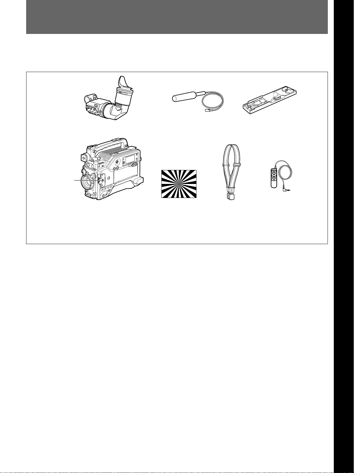
Product Configurations
The DSR-500WSL/500WSPL consists of the following items:
Chapter 1 Overview
Chapter 1 Overview
DXF-801/801CE Viewfinder
Switch guard*
DSR-500WS/500WSP
Camcorder
• Lens mount cap
• Binding tie
• Operating instructions
* The switch guard can be removed. (See page 12.)
Microphone (with the
wind screen attached)
Test chart for flange
focal length
adjustment
Shoulder strap
VCT-U14 Tripod
Adaptor
RM-LG1 Remote
Control Unit
Chapter 1 Overview 7
Page 8

Features
Features on Camera Section
2
/3-inch IT type Power HAD WS CCD
Chapter 1 Overview
The DSR-500WSL/500WSPL Digital Camcorder uses
a newly developed 520,000-pixel Power HAD WS
(wide screen) CCD, for outstanding sensitivity and
picture quality.
•Sensitivity: F11.0 (at 3200 K, 2000 lux)
•S/N: 63 dB
•Smear: –120 dB
Switchable between 16:9 and 4:3 aspect
ratios
A simple menu operation provides instant switching
between the 16:9 and 4:3 aspect ratios. In 4:3 mode, a
screen equivalent to a 4:3 screen is obtained through
digital processing of the 16:9 video signals produced
by the WS CCD. (See page 92.)
Wide-aspect ID signals
A menu setting is available to add wide-aspect ID
signals
Automatic aspect ratio switching in
viewfinder
When the supplied DXF-801/801CE viewfinder is
used, the viewfinder scan size automatically switches
in accordance with the aspect ratio (16:9 or 4:3)
selected for the camera. (See page 92.)
1)
to 16:9-mode video signals.
2)
(See page 92.)
Sophisticated image processing
TruEye™ processing makes possible the following
performance features. This digital signal processing
has brought reproduction of natural colors to the level
achieved by the human eye.
DynaLatitude™
Enables detailed adjustment of contrast control in each
pixel in accordance with a histogram of luminance
signal levels. (See pages 50, 81 and 88.)
DCC+ (dynamic contrast control plus)
Prevents white breakup when shooting a high intensity
subject, and also prevents color faults in high intensity
subject.
Black stretch and compress
Enables control of luminance signal levels in black
areas without changing the hue.
Variety of detail corrections
•Skin detail function: this function gives a slightly
softer appearance to the subject’s face. The target
skin color can be automatically set.
•Black halo correction
•Red/green vertical detail correction: this function
performs vertical detail compensation for both red
and green signals.
•Horizontal detail frequency control
Recording and managing setup data
In addition to the setup menu that is displayed in the
viewfinder screen, the DSR-500WSL/500WSPL is
equipped with the following functions to facilitate
camcorder setup.
Setup file system
You can use setup files when making adjustments or
settings. The DSR-500WSL/500WSPL comes with
factory preset files that contain shipped settings and
you can freely create user files as well. (See page 94.)
..........................................................................................................................................................................................................
1) ID signals complying with EIAJ CPR-1204 (DSR500WSL) or complying with ETS WSS (DSR500WSPL).
2) Video signals refer to the following:
• Video signals output from the VIDEO OUT connector
and MONITOR OUT connector.
• The Y component of Y/C separate signals and the Y
component of component signals output from the VTR
connector.
8 Chapter 1 Overview
Page 9

Automatic recording of setup data (page 99)
SetupLog™: Shooting-related environment settings
are recorded onto the tape at intervals of a few
seconds. This recorded data can be used to
reproduce the same shooting conditions in
subsequent shots. It also makes it easier to identify
the causes of problems in previous shots.
SetupNavi™: The setup conditions selected with the
setup menu and setup files are recorded onto the
tape. The recorded setup data can be copied to
other camcorders so that the same setup can be
shared among several camcorders.
Hyper gain
Hyper gain (36 dB or 42 dB, i.e. about 60 times or 120
times greater than 0 dB) can be easily set via one
switch setting. This can also be done from remote
equipment. (See pages 21, 22 and 88.)
Auto tracing white balance (ATW)
This function automatically traces the white balance,
which constantly changes as lighting conditions
change. Auto tracing white balance is especially useful
when there is no time to manually adjust the white
balance or when shooting moves between indoor and
outdoor locations. (See pages 13, 14 and 114.)
Chapter 1 Overview
Functions boost operability
Controlling with the RM-VJ1 Remote Control
Unit
You can control this unit while watching the image
with the optional RM-VJ1 Remote Control Unit
(equipped with the microphone and monitor). (See
page 41.)
EZ (easy) mode function
When there is no time to check the camcorder settings,
simply press the EZ MODE button to start the auto
adjustment function using standard settings. There is
no need to lose a shot for lack of setup time. (See
pages 13, 14, 90 and 91.)
EZ (easy) focus
Press the EZ FOCUS button before shooting to ensure
a quick and accurate focus. (See page 13.)
1)
Dual pixel readout (DPR
When the gain is set to either 18 dB or 24 dB, the gain
setting can be doubled (6 dB up) without increasing
the noise level.
Programmable gain
The amount of gain relative to the GAIN switch setting
(H, M, or L) can be programmed as –3 dB, 0 dB, 3 dB,
6 dB, 9 dB, 12 dB, 18 dB, 18 dB+DPR, 24 dB,
24 dB+DPR, and hyper gain. (See page 88.)
)
Total level control system (TLCS)
Even if the incoming light exceeds the range in which
the standard auto iris can control exposure, the auto
gain control (AGC) or auto exposure (AE) backs up to
ensure proper exposure. (See pages 14 and 90.)
Recording time (REC TIME) display
Recording time can be displayed in either of the
following modes. (See pages 21 and 82.)
2)
•Total recording time for all cuts (TTL
•Total recording time for current cut (DUR
)
3)
)
Viewfinder super detail
Video signals for the viewfinder are mixed with DTL
signals to make focusing easier.
Dual zebra pattern display
Two types of zebra patterns, zebra 1 and zebra 2 can
be displayed simultaneously or independently. The
zebra 1 can be set to the levels ranging from 70 to 90
IRE on the DSR-500WSL (or from 70 to 90% on the
DSR-500WSPL) and the zebra 2 indicates the levels of
100 IRE or more for the DSR-500WSL (or the levels
of 100% or more for the DSR-500WSPL). (See pages
13, 14 and 89.)
Color temperature display
When reading the white balance, the color temperature
is displayed on the viewfinder screen. (See page 112.)
..........................................................................................................................................................................................................
1) DPR = Dual Pixel Readout
2) TTL = Total
3) DUR = Duration
Chapter 1 Overview 9
Page 10

Features
Switching the color temperatures for the
preset white balance
You can select the preset white balance at 3200 K
(default) or 5600 K (default) by setting the FILTER
control. The preset white balance can be changed to
Chapter 1 Overview
other value through menu setting (See page 81).
Video monitor output with text
The video signal with text superimposed that is shown
in the viewfinder can also be output to an external
video monitor. (See pages 19 and 20.)
1-kHz reference signal output
Along with a color bar, a 1-kHz reference signal can
also be output. (See page 88.)
Freeze mix function
The freeze mix function superimposes any previously
recorded still picture on the viewfinder screen to
facilitate framing the subject when reshooting the
scene. (See page 60.)
Edit Search Function
Pressing the EDIT SEARCH buttons allows the tape to
play back in search mode. Set either of two playback
speeds. (See pages 13 and 59.)
Video light control
A video light connector and control switch are
equipped. You can turn the light on and off
automatically as you start and stop VCR operation.
(See page 13.)
Features on VCR Section
The DSR-500WSL/500WSPL uses the DVCAM
recording format. The internal signal processing is
digitalized to provide more stable output signals and
higher reliability.
Compatible with consumer DV
A DV cassette recorded on a DV-format VCR can be
played back on the DSR-500WSL/500WSPL.
(Cassettes recorded in LP mode cannot be played
back.) (See page 51.)
DVCAM cassettes (page 51)
•The DSR-500WSL/500WSPL can use both standardsize and mini-size DVCAM cassettes. According to
cassette size, the DSR-500WSL/500WSPL
automatically corrects reel position.
•The maximum recording/playback times are 184
minutes for standard size cassettes and 40 minutes for
mini cassettes.
•DVCAM cassettes include a cassette memory.
Information about the editing points (ClipLink™ log
data) that is specified while shooting is recorded into
this cassette memory.
Recordable the external video signals
High-performance DXF-801/801CE
Viewfinder (page 118)
•Switching the aspect ratio automatically between
16:9 and 4:3
•High resolution (600 TV lines of horizontal
resolution)
•Large-diameter eye cup for easier viewing and
focusing
•PEAKING potentiometer for vertical and horizontal
detail control
•Three indicators can be used as TALLY indicators
•Tough die-cast aluminum body
•DISPLAY switch that can turn the character display
on and off
•Light that can light the lens control elements
10 Chapter 1 Overview
Fitting the optional DSBK-501/501P Analog
Composite Input Board enables the camcorder to
record the external analog video signals. (See pages
24, 56 and 81.)
Page 11

ClipLink™ function
Color playback
The ClipLink function links all stages from shooting to
editing. Once editing points have been set with this
function during shooting, they can be used to boost the
efficiency of editing work.
However, this function does not work when using the
DV OUT connector. (See pages 68, 109 and 136.)
Creation of clips
Using the ClipLink function, the camcorder operator
can create clips to be used during editing.
The images captured at the Mark IN points are
recorded in a compressed format onto the tape as
“Index Pictures.” In addition, editing point-related data
(scene number, time code for Mark IN/OUT points,
etc.) is recorded in the cassette memory.
ClipLink mode
To use the ClipLink function, select the menu setting
to set the DSR-500WSL/500WSPL into ClipLink
mode. There is also a ClipLink continue function that
enables clips to be continued even after a break in
recording.
PCM digital audio
Connect an external video monitor for color playback
(playback adaptor not required). The DSR-500WSL/
500WSPL is equipped with two video monitor
connectors: one for composite video output and the
other for S-video output. (See page 24.)
VCR data display
The DSR-500WSL/500WSPL is able to display the
following data on the viewfinder screen. (See pages
76, 89 and 90.)
•Time values (counter, time code, or user bit values)
•Audio recording levels
•Remaining tape time
•Operation mode of the VCR section
•Remaining battery capacity
•ClipLink information
Recording on external VCRs
Betacam or S-VHS VCRs can be connected to the
VTR connector (26-pin) on the rear panel. (See pages
25, 26, 45 and 56.)
Chapter 1 Overview
Recording/playback can be set to audio lock mode.
Selectable between two-channel recording (with a
sampling frequency of 48 kHz) mode or four-channel
recording (with a sampling frequency of 32 kHz) mode
(CH-1 and CH-2 only). (See pages 16, 17, 55 and
109.)
Equipped with the DV OUT connector
The DV OUT connector is i.LINK
can connect with the Sony equipment which has the
DV input connector.
1)
compatible. You
You can do cut editing and digital dubbing if you
connect the DSR-70/70P Digital Videocassette
Equipped with audio output connectors
Recorder (with the DSBK-140 is fitted) to the DV
OUT connector on the camcorder, using an i.LINK
During recording or playback, audio output can be
monitored via a built-in speaker, a connected earphone
cable (DV connecting cable). (See pages 25, 26, 45
and 57.)
or via (two-channel) audio output connectors. (See
pages 24 and 25.)
..........................................................................................................................................................................................................
1) is a trademark of Sony Corporation and indicates that
this product is in agreement with IEEE 1394-1995
specifications and their revisions.
Chapter 1 Overview 11
Page 12

Location and Function of Parts
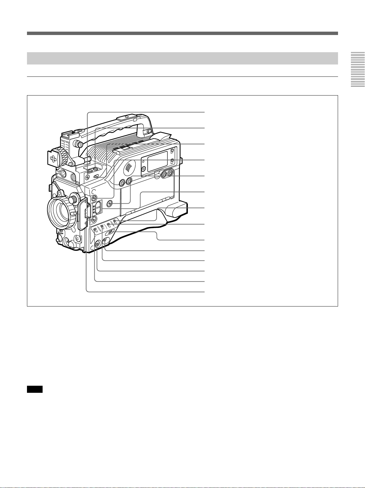
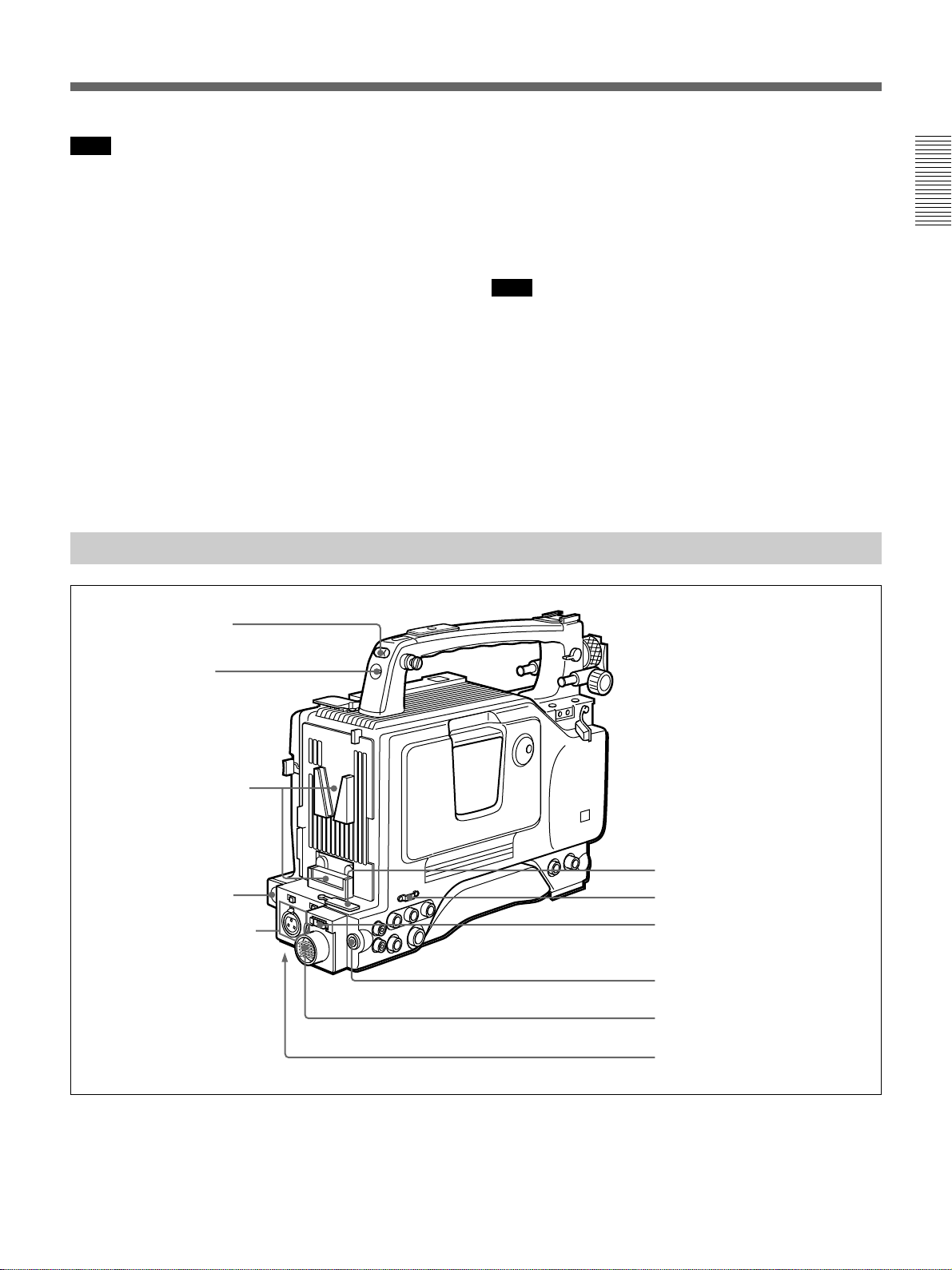
Front View
Chapter 1 Overview
0 Switch guard
How to remove the switch guard
1. Detach the two screws (M3).
2. Remove the switch guard, and replace the
screws detached in step 1.
1 MIC IN +48 V connector
2 VF connector
3 FILTER control
4 Lens mount
5 SHUTTER switch
Switch guard
1 MIC (microphone) IN +48 V connector (XLR 3pin, female)
Connect the supplied microphone or an optional
microphone (operable with a 48 V supply).
2 VF (viewfinder) connector (20-pin)
This is the connector for the DXF-801/801CE
viewfinder.
3 FILTER control
Select the color temperature conversion filter
appropriate to the lighting conditions.(See page 49.)
4 Lens mount
Attach the optional zoom lens here.
5 SHUTTER switch
Use this switch to set the shutter speed, CLS (clear
scan), or EVS setting (see page 116).Usually, set this
switch to OFF.
6 TAKE button
7 AUDIO LEVEL knob
8 WHT/BLK switch
9 VTR button
6 TAKE button
Press this button to specify an editing point (Mark IN/
OUT or Cue point) at the current tape position during
shooting.(See pages 70 and 71.)
7 AUDIO LEVEL knob
You can use this knob to manually adjust the channel 1
audio recording level.
8 WHT/BLK (white/black) switch
This switch is used for automatic adjustment of the
white balance and black balance.(See pages 112 to
115.)
9 VTR button
Pressing this button starts and stops recording on the
VCR.
0 Switch guard
Avoids miss-operation of the EZ MODE button (4 on
page 14), A.IRIS MODE switch (6 on page 14), and
ATW button (qf on page 14). When using these
buttons and switch, open the guard.
12 Chapter 1 Overview
Page 13
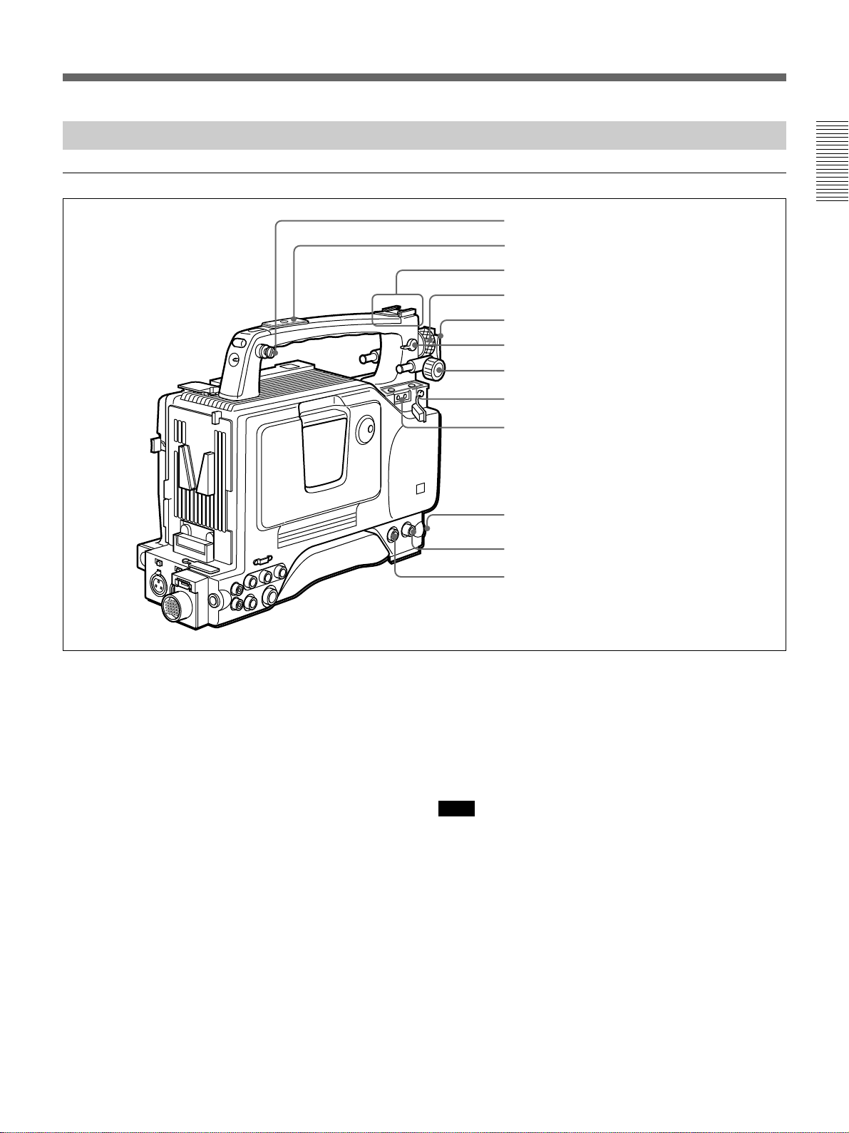
Right Side View
Front section
Chapter 1 Overview
1 EZ FOCUS button
2 EDIT SEARCH buttons
3 LIGHT switch
4 EZ MODE button and indicator
5 ZEBRA button and indicator
6 A.IRIS MODE switch and indicator
7 MENU switch
8 W. BAL switch
1 EZ FOCUS button
Press this button to turn the “easy focus” function on.
This opens the iris, to make it easier to focus before
beginning shooting. The indication “EZ FOCUS”
appears in the viewfinder while the function is on; to
turn it off, press the EZ FOCUS button again. If left
on, the function automatically turns off after about ten
seconds.
Note
If the “easy focus” function is still on when you press
the VTR button on the camcorder or the lens, it turns
off automatically and recording starts about one
second later.
9 MENU dial
0 POWER switch
qa OUTPUT/DL/DCC+ switch
qs NG button
qd GAIN switch
qf ATW button and indicator
2 EDIT SEARCH buttons
You can see the search playback while pressing either
of these buttons at recording pause mode to quickly
find the next recording start point. Two playback
speeds are available, and press either of the buttons to
the inner position to increase the speed.
3 LIGHT (video light) switch
Controls the video light connected as follows.
AUTO: turns on the video light at recording if the
power switch on the light is set on.
MAN (manual): allows the power switch on the
video light to turn the light on and off.
Chapter 1 Overview 13
Page 14

Location and Function of Parts
4 EZ (“easy”) MODE button and indicator
Press this button (EZ mode on) when you want to be
able to shoot immediately, with automatic adjustment
of the camcorder settings to standard values. (See page
91 for EZ mode settings.) When this function is used,
Chapter 1 Overview
the iris and the white balance are adjusted
automatically. (The total level control system
functions.) Press this button again to return the
camcorder to the previous settings (EZ mode off).
Note
When the RM-M7G Remote Control Unit is connected
or external analog signals are input, the “easy mode”
function is disabled.
5 ZEBRA button and indicator
Depress this button to display a zebra pattern (diagonal
stripes) in the viewfinder.
Depending on the zebra setting in advanced menu page
4 (see page 89), the zebra 1 for video levels between
70 to 90 IRE (or 70 to 90%) and the zebra 2 for video
levels 100 IRE or more (or 100% or more) can be
displayed independently or simultaneously.
0 POWER switch
Powers the camcorder on or off.
OUTPUT/DL/DCC+ (Color bar output/
qa
DynaLatitude/dynamic contrast control plus) switch
Use this switch to select the DCC+ function, the
DynaLatitude function, or color bar output.
Select the CAM/DCC+ position in most cases.
CAM/DCC+: This activates the DCC+ function.
This prevents color faults when shooting highintensity subjects.
CAM/DL: This setting uses the DynaLatitude
function, which finely adjusts the contrast of each
pixel according to a histogram of luminance signal
levels. Access advanced menu page 2 to set the
DynaLatitude function ON or OFF. The
DynaLatitude effect can be set to any of three
levels, Low, STD (standard), and High with basic
menu page 2.
BARS: This setting displays color bars.
For details of menu operation, see Chapter 4 “Viewfinder
Screen Indications and Menus”.
6 A.IRIS (auto iris) MODE switch and indicator
When you use the auto iris function (by setting the
IRIS selector on the lens to A), set this switch to suit
the shooting conditions. Selecting BACK L gives more
light to back-lit subjects, and selecting SPOT L adjusts
for high contrast in spot-lit subjects. For normal
shooting, set this switch to STD.
7 MENU switch
When you press this switch to the ON position, the
basic menu is displayed. Keep pressing it to the ON
position to cycle through the various menu displays.
When you press the switch to the STATUS position,
the camcorder’s status (of current settings) is
displayed.
8 W. BAL (white balance) switch
This selects the white balance setting from the preset
value, the value in memory A or the value in memory
B. (See page 113.) You can select the preset white
balance at 3200 K or 5600 K using the FILTER
control (3 on page 12). You can change the preset
color temperature on basic menu page 2. (See page
81.)
qs NG button
When using the ClipLink function during shooting,
you can designate a particular scene as “NG” (No
Good) by pressing this button before shooting the next
scene. Press the button again to cancel the NG setting.
qd GAIN switch
This selects one of the three gain settings, high,
medium or low. You can choose the gain values
assigned to the H, M and L settings from values from
–3 dB to 24 dB + DPR, and hyper gain. (See page 88.)
The factory default selections are 18 dB (H), 9 dB (M)
and 0 dB (L).
Note
When the HYPER GAIN switch (7 on page 22) is in
the ON position, the GAIN switch has no effect.
qf ATW (auto tracing white balance) button and
indicator
Press this button, turning the indicator on, when you
want the white balance to be adjusted automatically to
follow changes in lighting conditions. (See page 114.)
9 MENU dial
Use this dial to change menu pages or settings.
14 Chapter 1 Overview
Page 15
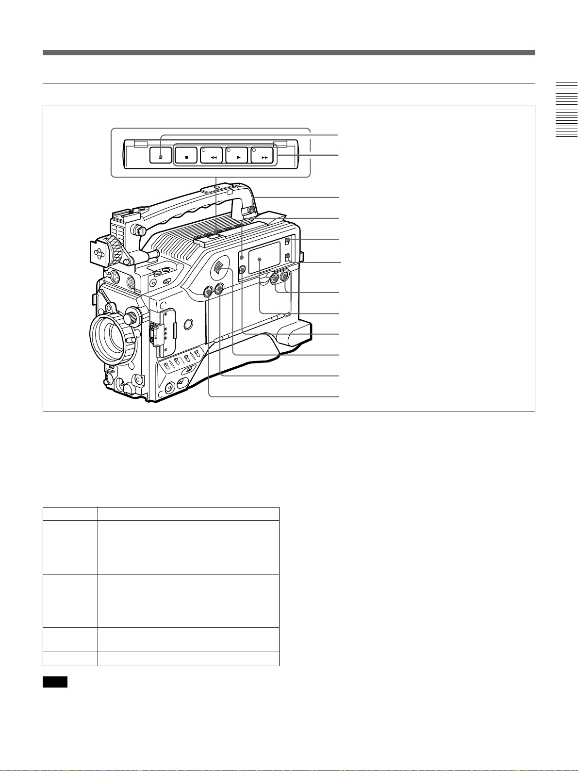
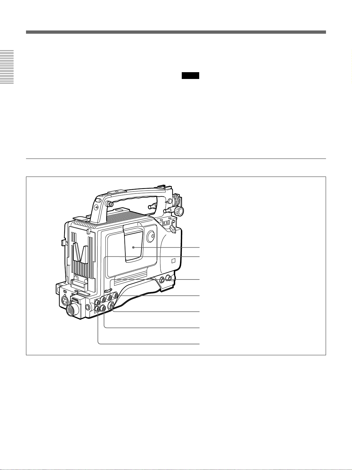
Rear section
EJECT
STOP
1 EJECT button
F FWD
PLAYREW
2 Tape transport buttons and indicators
3 EARPHONE connector
4 WARNING indicator
5 LIGHT switch
6 DISPLAY switch
7 AUDIO LEVEL (CH-1/CH-2) knobs
8 Display window
9 RESET/(MENU SET) button
0 Speaker
qa ALARM knob
qs MONITOR knob
Chapter 1 Overview
1 EJECT Z button
Press to open the cassette holder (1 on page 24) when
the camcorder is powered.
2 Tape transport buttons and indicators
These buttons transport the tape as shown below.
Buttons
REW m
F FWD M Fast forwards the tape. The indicator lights
PLAY N Plays back the recorded video. The indicator
STOP x
Note
Operation
Rewinds the tape. The indicator lights while
the tape is being rewound.
Press while the tape is being rewound or
during playback to view reverse search
playback.
while the tape is being fast forwarded.
Press while the tape is being fast forwarded
or during playback to view forward search
playback.
lights during playback.
Stops the tape.
During recording, none of these buttons operates.
3 EARPHONE connector (mini-jack)
Connect an earphone or headphones. This outputs the
sound which was output to the speaker (0 on page
18), but mutes the speaker.
4 WARNING indicator
This lights or blinks when an abnormality occurs.
For details, see “Warning System” on page 127.
5 LIGHT switch
This switches the display window (8 on page 16)
light on or off.
6 DISPLAY switch
Switches time value indication shown in the display
window (8 on page 16).
COUNTER: Shows the tape transport time in
HH:MM:SS (hours, minutes and seconds).
TC: Shows the time code value.
U-BIT: Shows the user bit data in the time code.
Chapter 1 Overview 15
Page 16
Location and Function of Parts
7 AUDIO LEVEL (CH-1/CH-2) (audio recording
level adjustments for channels 1 and 2) knobs
When the AUDIO SELECT (CH-1/CH-2) switches
(4 on page 20) are set to MAN, these knobs adjust
the audio levels being recorded on channels 1 and 2.
Chapter 1 Overview
A Playback indication
PB DATE NDF EXT-LK HOLD
S Time value
indication
R Clip remaining
indication
Q Tape remaining
indication
P Battery capacity
indication
O Service indication
1) When the optional DSBK-301A is fitted.
CLIP
TAPE
BATT
DIAG
The audio levels are indicated in the display window 8.
For details, see “8 Display window” below.
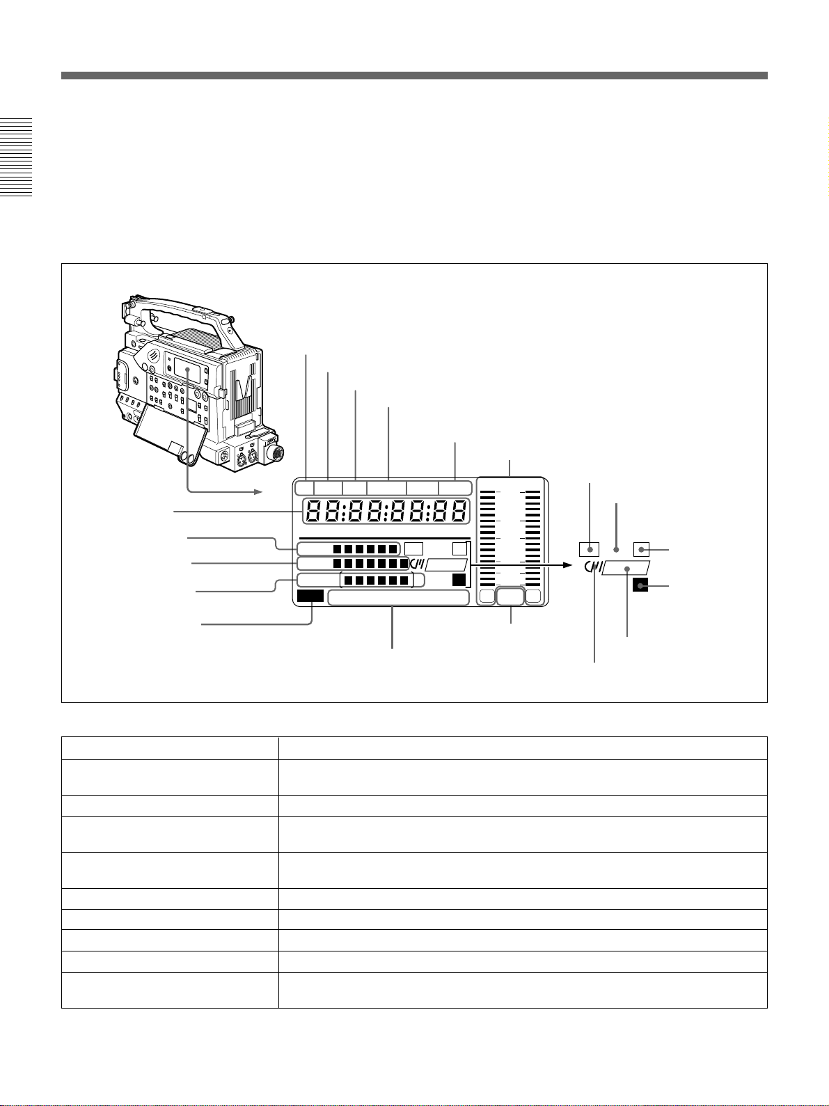
8 Display window
Shows the following items. Use the LIGHT switch (5
on page 15) to light up the display window.
B DATE indication
C Non-drop frame indication (DSR-500WSL only)
D External synchronization lock indication
E Hold indication
F Audio level indicators
dB
OVER OVER
0
H MIN SEC FRM
CONT
DVCAM
IP
Li
CL
EF
RF SERVO HUMID SLACK
M Audio mode indications
N Warning indications
-12
-20
-30
-40
∞
-
F
s 32k
1
F
s 48k
G ClipLink log data indication
H ClipLink continue
indication
CL
CONT
IP
I IP indication
1)
DVCAM
Li
2
K DVCAM indication
L Cassette memory indication
J Lithium backup
battery warning
Indications in the display window
Indication
Description
A Playback indication Appears during playback, fast forward or rewind with the time data display showing a
time code or user bit value.
B DATE indication Appears when the date or time is displayed in the time value indication S area.
C Non drop-frame indication (DSR-
Appears when non-drop frame mode is selected.
500WSL only)
D External synchronization
indication
Appears when the internal time code generator is locked to an external signal input to
the TC IN connector (3 on page 24).
E Hold indication Appears when the internal time code generator is stopped.
F Audio level indicators These show the audio recording or playback levels of channel 1 and channel 2.
G ClipLink log data indication
H ClipLink continue indication
Appears when using a cassette with cassette memory containing ClipLink log data.
Appears when back space editing using ClipLink function is possible.
I IP(Index Picture) indication Appears when the ClipLink function is set to on in the VCR menu and Index Picture
recording is allowed. (The optional DSBK-301A is required.)
16 Chapter 1 Overview
Page 17

Indication Description
J Lithium backup battery warning Appears when the voltage of the internal lithium backup battery (CR2032) is low. If this
indication appears, replace the lithium backup battery immediately.
For further information about replacing lithium battery, see “Inserting and Replacing
the Lithium Battery” (page 31).
K DVCAM indication Disappears when the cassette being played back is not for DVCAM format.
L Cassette memory indication Appears when using a cassette with cassette memory.
M Audio mode indications These show audio recording/playback mode.
Fs32k: 4-channel mode (32kHz sampling frequency)
Fs48k: 2-channel mode (48kHz sampling frequency)
For further information about selecting audio recording mode, see “Menu 212
Selecting Audio Recording Mode” (page 109).
N Warning indications Include the following.
RF: Appears when the video heads are clogged, or when there is a fault in the
recording system.
SERVO: Appears when the servo lock is not functioning.
HUMID: Appears when there is condensation on the drum.
SLACK: Appears when there is a tape winding fault.
For measures against warning indications, see “Warning System” (page 127).
O Service indication Appears during maintenance or VCR menu operations (page 103). It does not appear
during normal operation.
P Battery capacity indication
This indicates the battery capacity and voltage as shown below.
Change menu setting for the battery you are using.
Chapter 1 Overview
For menu settings, see “Menu 206 Selecting Battery Capacity Indication” (page 106).
Battery voltage
Indication BP-L40/L40A/L60/ NP-1B/BP-90A
L60A/L90/L90A
BATT E[xxxxxx]F 15.0 V or more 12.5 V or more
BATT E[xxxxxp]F 14.0 to 15.0 V 12.0 to 12.5 V
BATT E[xxxxpp]F 13.0 to 14.0 V 11.75 to 12.0 V
BATT E[xxxppp]F 12.0 to 13.0 V 11.5 to 11.75 V
BATT E[xxpppp]F 11.3 to 12.0 V 11.3 to 11.5 V
1)
BATT E[xxpppp]F (blinking)
BATT E[xppppp]F (blinking) 11.0 to 11.25 V 11.0 to 11.25 V
BATT E[pppppp]F (blinking) 11.0 V or less 11.0 V or less
1)Replace the battery pack when this indication appears.
11.25 to 11.3 V 11.25 to 11.3 V
(Continued)
Chapter 1 Overview 17
Page 18

Location and Function of Parts
Indication Description
Q Tape remaining indication During recording or pause mode, this indication shows the remaining tape time as
shown below. It is not displayed when no cassette is loaded.
Indication Tape time remaining
Chapter 1 Overview
R Clip remaining indication This shows how many clip shots or Cue points can be recorded
TAPExxxxxxx 30 minutes or more
TAPExxxxxx 25 to 30 minutes
TAPExxxxx 20 to 25 minutes
TAPExxxx 15 to 20 minutes
TAPExxx 10 to 15 minutes
TAPExx 5 to 10 minutes
TAPEx 2 to 5 minutes
TAPEx (blinking) 0 to 2 minutes
TAPE (blinking) End of tape
1)
.
Indication Clip shots Cue point
CLIPxxxxxx 51 or more 101 points or more
CLIPxxxxx 41 to 50 81 to 100 points
CLIPxxxx 31 to 40 61 to 80 points
CLIPxxx 21 to 30 41 to 60 points
CLIPxx 11 to 20 21 to 40 points
CLIPx 1 to 10 1 to 20 points
CLIPx (blinking)
CLIP Cannot record
CLIP (blinking)
2)
2)
1 to 3 1 to 6 points
Cannot record
1) The optional DSBK-301A is required for Index Picture recording.
2) When back space editing using ClipLink function is possible (when CONT is
displayed).
S Time value indication Depending onthe DISPLAY switch (6 on page 15) setting, this shows a counter value,
9 RESET/(MENU SET) (counter reset/VCR
menu) button
Resets the time value shown in the display window.
This button operates differently depending on settings
of the DISPLAY switch (6 on page 15), and the TC
mode switches 1 (9 on page 20) and 2 (8 on page
20).
Switch setting RESET button operation
DISPLAY: COUNTER Resets counter value to
DISPLAY: TC
TC mode switch 1: PRESET
TC mode switch 2: SET
DISPLAY: U-BIT
TC mode switch 1: PRESET
TC mode switch 2: SET
time code value or user bit value. Press the MENU button (1 on page 19) to display
the VCR menu.
a) Bits of time code recorded on tape, in which users can
record necessary information.
Also, this button is used to change VCR menu settings.
For details on the VCR menu, see “Setting on the VCR
Section VCR Menu” (page 103).
0 Speaker
Outputs the recorded or playback audio. When a
0:00:00.
Resets time code to
00:00:00:00.
warning indicator appears in the viewfinder or display
window, the speaker sounds a warning tone.
The speaker is muted (does not output a warning tone)
when an earphone is connected to the EARPHONE
Resets user bit
00 00 00 00.
a)
to
connector (3 on page 15).
For details on the warning tone, see “Warning System”
(page 127).
18 Chapter 1 Overview
Page 19
qa ALARM (alarm tone volume adjustment) knob
Controls the volume of the warning tone that is output
via the speaker (0 on page 18) or the EARPHONE
connector (3 on page 15). Turning this knob to the
minimum setting mutes the alarm tone.
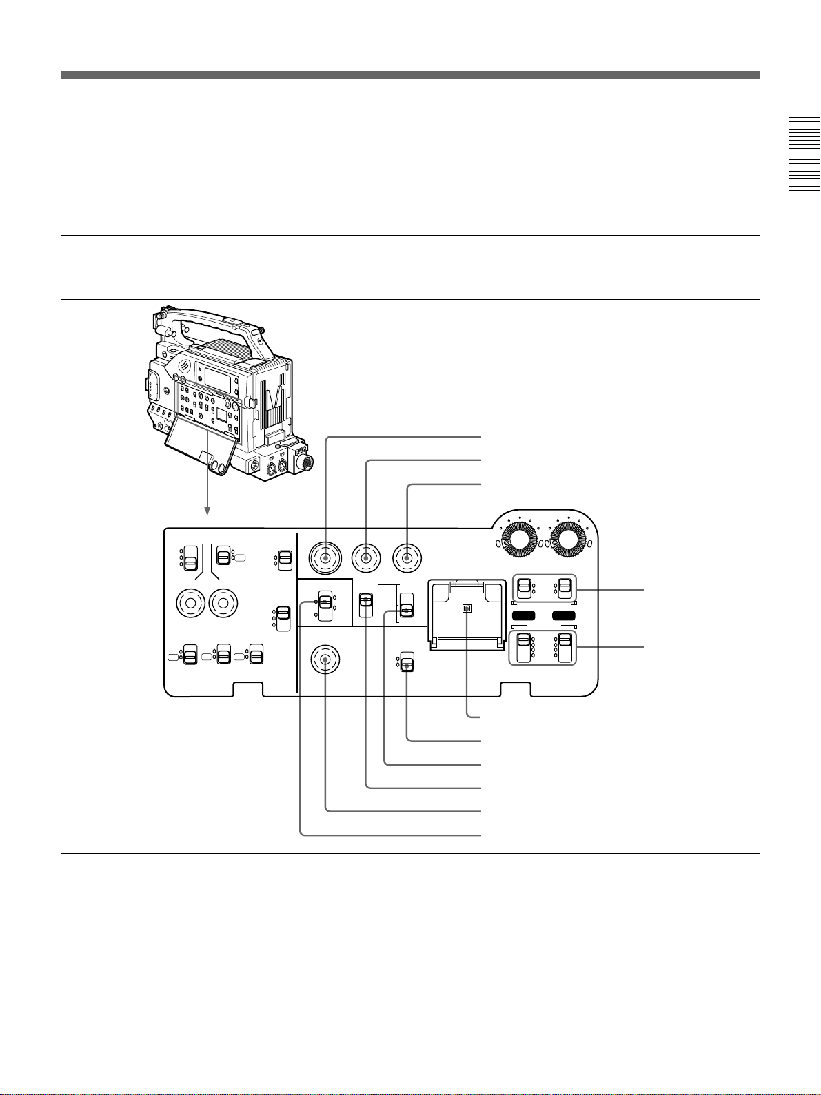
Operation panel under the cover
Right side
qs MONITOR (monitor volume adjustment) knob
Controls the volume of the sound other than the
warning tone that is output via the speaker (0 on page
18) or the EARPHONE connector (3 on page 15).
Turning this knob to the minimum setting mutes the
audio output.
1 MENU button
2 ADVANCE button
3 SHIFT button
Chapter 1 Overview
MENU
ClipLink
ADVANCE SHIFT
PRESET
CH-1
CH-2
DATE/TIME
REC TIME SKIN DTL EXT VTR
TTL
DUR
OFF
TTL RESET
ON
OFF
HYPER
GAIN
SET
SETUP
FILE
STD
ON
COMPONENT.
OFF
PARALLEL
INT ONLY
EXT ONLY
FRONT MIC
LOW CUT
ON
OFF
OUTPUT
VBS
Y/C
VTR
TRIGGER
MONITOR SELECT
MIX
EXT
CONTINUE
1 MENU button
Press this button to display the VCR menu in the
display window.
For details about the VCR menu, see “Setting on the VCR
Section —VCR Menu” (page 103).
REGEN
ON
OFF
AUDIO LEVEL
F-RUN
F-RUN
R-RUN
MONITOR OUT
CHARACTER
SET
LITHIUM BATT
AUTO
MAN
AUDIO SELECT
CH-1
AUDIO IN
FRONT
VJ MIC
WRR
REAR
CH-2
4 AUDIO SELECT
(CH-1/CH-2)
switches
5 AUDIO IN (CH-1/
CH-2) switches
6 Lithium battery compartment
7 MONITOR OUT CHARACTER switch
8 TC mode switch 2
9 TC mode switch 1
0 ClipLink CONTINUE button
qa MONITOR SELECT switch
been selected with the SHIFT button (3 on page 20).
In other case, keep pressing this button to show the
clip remaining indication instead of time value.
(Example: CLIP 045)
For time code and user bit settings, see pages 62 to 65.
2 ADVANCE button
When setting time code and user bit values, or at menu
setting, press this button to increment the digit that has
On how to use the ADVANCE button for menu settings, see
“Setting on the VCR Section —VCR Menu” (page 103).
Chapter 1 Overview 19
Page 20

Location and Function of Parts
3 SHIFT button
When setting time code and user bit values, or at menu
setting, keep pressing this button to select a digit. The
selected digit will start blinking.
In other case, keep pressing this button to show the
Chapter 1 Overview
date (when the DISPLAY switch (6 on page 15) is
set to U-BIT) and time (when the DISPLAY switch is
set to TC) instead of time value.
For time code and user bit settings, see pages 62 to 65.
On how to use the SHIFT button for menu settings, see
“Setting on the VCR Section —VCR Menu” (page 103).
4 AUDIO SELECT (CH-1/CH-2) (audio recording
level adjustments manual/auto selection for
channels 1 and 2) switches
These select the audio recording level adjustment
method.
AUTO: Use the AGC (automatic gain control) circuit
to automatically adjust the audio level.
MAN(MANUAL): Enables users to manually adjust
the AUDIO LEVEL (CH-1/CH-2) knobs (7 on
page 16) for each channel. Select AUTO if excess
input levels are likely to occur.
5 AUDIO IN (CH-1/CH-2) (audio input selection
for channels 1 and 2) switches
These select the input signals to channels 1 and 2.
FRONT: Signals from the microphone connected to
the MIC IN +48 V connector (1 on page 12).
VJ MIC: Signals from the remote control unit with
microphone connected to the REMOTE connector
2 (qa on page 24).
WRR: Signals from the WRR-855A synthesized
tuner connected to the WRR connector (6 on
page 26) via the CA-WR855 Camera Adaptor.
REAR: Signals from a microphone or external
equipment connected to the AUDIO IN (CH-1/
CH-2) connectors (5 on page 26).
6 Lithium battery compartment
Insert the supplied CR2032 Lithium Battery.
On how to fit the lithium battery, see page 31.
Note
Set this switch ON when using the freeze mix
function.
8 TC (time code) mode switch 2
Sets the mode for advancing time code values when
the TC mode switch 1 9 has been set to PRESET.
F-RUN: The time code advances continuously
whether or not the camcorder is recording. Use
this setting to align the time code value with real
time.
SET: Use this setting to set the time code or user bit
value.
R-RUN: The time code value advances only during
recording. Use this setting to have consecutive
recordings on the tape.
Note for the DSR-500WSL
There are two time code frame modes: drop-frame
(DF) mode and non drop-frame (NDF) mode. This
product is shipped with drop-frame mode selected.
For details on switching between drop-frame mode and non
drop-frame mode, see “Selecting Frame Mode (DF/NDF)
for Time Code (for DSR-500WSL Only) —Menu 204” (page
105).
For details on drop-frame mode and non drop-frame mode,
see “Drop-frame mode (for DSR-500WSL only)” on page
65.
9 TC (time code) mode switch 1
Selects between resetting the time code value or
continuing from the time code value at the end of the
previous recording.
PRESET: This starts recording time code values on
the tape from the currently set value.
REGEN: During back space editing, this reads the
tape’s current time code value and sets the time
code to record starting from that value. The time
code value is advanced in R-RUN mode
regardless of the setting on TC mode switch 2 8.
DATE/TIME: This synchronizes the time code to
the real time clock set in the VCR menu (see page
105). In this case the time code of the DSR500WSL is recorded in DF (drop-frame mode).
7 MONITOR OUT (monitor output)
CHARACTER switch
Set ON to superimpose text information on the
monitor output.
20 Chapter 1 Overview
Page 21
Note
If the ClipLink function is set to on (meaning ClipLink
shooting is allowed) in menu 211 and CONT is
displayed in the display window, regardless of the
setting of this switch, the time code generator
automatically enters the REGEN mode at recording.
(The ClipLink function is set to OFF at factory.) When
you will not perform ClipLink shooting, set the
ClipLink function to oFF (see page 109).
0 ClipLink CONTINUE button
When restart ClipLink shooting, press this button to
add the new clip at the end of the recorded clips.
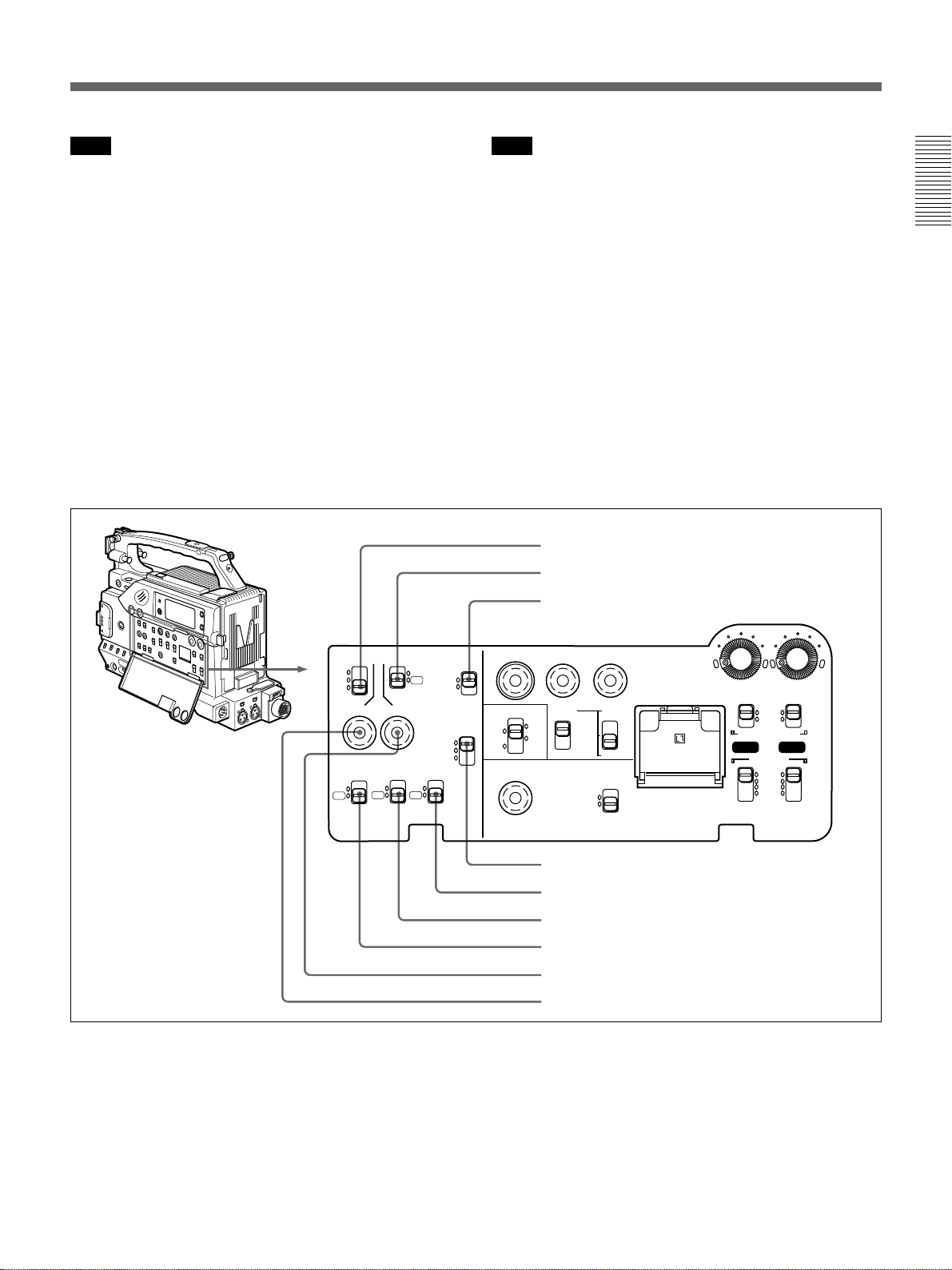
Left side
Note
When restart recording without pressing this button,
the pre-recorded ClipLink log data and Index Pictures
are deleted.
Chapter 1 Overview
For details , see “ClipLink Shooting” (page 68).
qa MONITOR SELECT (audio monitor selection)
switch
Selects audio output via the speaker (0 on page 18) or
earphone.
CH-1: Channel 1 audio
MIX: Mixed audio (channels 1 and 2)
CH-2: Channel 2 audio
EXT: The sound selected by an external VCR
connected to the VTR connector (0 on page 26)
1 REC TIME switch
2 SKIN DTL switch
3 EXT VTR OUTPUT switch
REC TIME SKIN DTL EXT VTR
TTL
DUR
OFF
TTL RESET
ON
OFF
HYPER
GAIN
SET
SETUP
FILE
STD
ON
COMPONENT.
OFF
PARALLEL
INT ONLY
EXT ONLY
FRONT MIC
LOW CUT
ON
OFF
OUTPUT
VBS
TRIGGER
1 REC (recording) TIME switch
Selects the recording time indication in the viewfinder.
TTL (TOTAL): Displays the total recording time.
The total recording time is not reset even when
you stop the VCR and power off the camcorder,
for example, to replace the battery pack.
DUR (DURATION): Displays the recording time of
the current cut.
Y/C
VTR
MENU
ADVANCE SHIFT
AUDIO LEVEL
MONITOR SELECT
CH-1
MIX
CH-2
EXT
ClipLink
CONTINUE
PRESET
DATE/TIME
REGEN
OFF
F-RUN
F-RUN
R-RUN
MONITOR OUT
CHARACTER
ON
SET
LITHIUM BATT
AUTO
MAN
AUDIO SELECT
CH-1
AUDIO IN
FRONT
VJ MIC
WRR
REAR
CH-2
4 VTR TRIGGER switch
5 FRONT MIC LOW CUT switch
6 SETUP switch
7 HYPER GAIN switch
8 SKIN DTL SET button
9 TTL RESET button
OFF: Switches off the recording time display.
If, however, in advanced menu page 6 you set the
time code display item (TC IND) to ON (see page
90), then the VCR time data (time code, counter,
or user bit value) is displayed.
(Continued)
Chapter 1 Overview 21
Page 22

Location and Function of Parts
Note
The recording time displayed when this switch is set to
TTL or DUR is obtained by counting the duration of
the internal reference signal input to the camcorder.
The value may not agree exactly with the value
Chapter 1 Overview
derived from the time code values. Furthermore, the
value displayed may not be correct when another
manufacture’s VCR is connected to the camcorder.
2 SKIN DTL (skin detail) switch
Set this switch ON to use the skin detail correction
function.
For details, see “Skin Detail Correction” (page 123).
3 EXT VTR OUTPUT switch
Depending on the external VCR connected to the VTR
connector (0 on page 26), this switches the video
signal output to the VCR.
COMPONENT/VBS: Component/composite video
signal
Y/C: S-video signal
7 HYPER GAIN switch
Setting this switch to the ON position increases the
gain by a factor of about 60 or 120 with respect to 0
dB (a 30 or 36 dB increase by electronic amplification
and a 6 dB increase for DPR, bringing about a total
gain increase of 36 or 42 dB).
When this switch is in ON position, the indication
“HYPER” appears in the viewfinder, and the GAIN
UP indicator in the viewfinder also lights.
When finished shooting, return this switch to OFF
position. The HYPER indication disappears and the
GAIN UP indicator goes out.
Note
Increasing the gain with this switch reduces the
horizontal resolution by approx. 50%.
8 SKIN DTL (skin detail ) SET button
Press this button with the SKIN DTL switch 2 has
been set to ON to display the area detect cursor on
viewfinder screen. Place the cursor on the target and
press this button to perform skin detail correction.
4 VTR TRIGGER switch
Sets the function of the VTR button on the camcorder
or lens when a VCR is connected to the VTR
connector (0 on page 26).
PARALLEL: Operates both internal and external
VCRs.
INT ONLY: Operates the internal VCR only.
External VCR operation is performed locally.
EXT ONLY: Operates the external VCR only.
5 FRONT MIC LOW CUT switch
Set this switch to ON to insert a high-pass filter in the
microphone circuit, reducing wind noise.
Normally leave the switch in the OFF position.
6 SETUP switch
Use this switch to select the camcorder setup method.
FILE: Set up using setup files and the setup menu.
STD: Set up using the setup menu.Setup file data is
not displayed.
For details, see “Skin Detail Correction” (page 123).
9 TTL (total) RESET button
Pressing this button resets the total recording time
(TTL selection) to 0.
22 Chapter 1 Overview
Page 23
Left and Upper View
Front section
1 Shoulder strap fitting
Chapter 1 Overview
2 Attachment shoe for large viewfinder
3 Accessory fitting shoe and screw hole
4 Viewfinder left-to-right positioning ring
5 Viewfinder fitting shoe
6 REMOTE connector 1
7 Viewfinder front-to-back position locking knob
8 Fitting for optional microphone holder
9 Video light connector
0 LENS connector
qa VIDEO OUT connector
1 Shoulder strap fitting
To use the supplied shoulder strap, fix one end here
and the other end to the right side.(See page 38.)
2 Attachment shoe for large viewfinder
This allows you to attach the optional electronic
viewfinder. (See page 35.)
3 Accessory fitting shoe and screw hole
Attach optional video lights or other accessories here.
(See page 37.)
4 Viewfinder left-to-right position fixing ring
Loosen this ring to adjust the left-to-right position of
the viewfinder. (See page 34.)
5 Viewfinder fitting shoe
Fix the DXF-801/801CE Viewfinder here. (See page
34.)
6 REMOTE connector 1 (mini-jack)
Connect the RM-LG1 Remote Control Unit to enable
remote operation of the ClipLink function.
qs REMOTE connector 2
If you connect the optional cable (Sony part number:
1-790-779-11) to this connector, you can control the
zoom using the optional RM-VJ1 Remote Control Unit
(equipped with microphone and monitor), even if you
use the conventional lens.
For details, consult your Sony dealer.
Note
The RM-81 cannot be connected.
7 Viewfinder front-to-back position locking knob
Loosen this knob to adjust the front-to-back position of
the viewfinder. (See page 34.)
8 Fitting for optional microphone holder
You can fit an optional CAC-12 Microphone Holder
here. (See page 36.)
9 Video light connector
A video light with a maximum power consumption of
30 W such as the Anton Bauer Ultralight 2 or
equivalent can be connected. (See page 37.)
Chapter 1 Overview 23
Page 24
Location and Function of Parts
0 LENS connector (12-pin)
Connect the lens cable.
qa VIDEO OUT connector (BNC)
This outputs the video signal captured by the
Chapter 1 Overview
camcorder.
qs REMOTE connector 2 (10-pin)
Connect the optional RM-M7G Remote Control Unit
to this connector. Set the CAMERA SELECT switch
on the bottom of RM-M7G to 1.
Rear section
You can also connect the RM-VJ1 Remote Control
Unit (equipped with microphone and monitor.)
Notes
•EZ mode cannot be used if the RM-M7G is
connected to the camcorder.
•Be sure to turn off the power of the camcorder before
connecting the RM-M7G/VJ1.
•Be sure to turn off the power of the camcorder before
disconnecting the equipment connected to this
connector. Otherwise, the camcorder will not work
properly.
1 Cassette holder
Power the camcorder and press the EJECT button to
open the lid. Insert the cassette and close the lid by
pressing the indication “PUSH”.
2 GEN LOCK IN (gen lock video input)/VIDEO
IN (video input) connector (When the optional
DSBK-501/501P is fitted) (BNC)
GEN LOCK IN: When synchronizing the camcorder
to an external signal, input a reference video
signal (VBS or BS). (See page 81.)
1 Cassette holder
2 GEN LOCK IN/VIDEO IN connector (When
the optional DSBK-501/501P is fitted)
3 TC IN connector
4 TC OUT connector
5 S VIDEO OUT connector
6 MONITOR OUT connector
7 AUDIO OUT CH-1/CH-2 connectors
VIDEO IN: When the optional DSBK-501/501P
Analog Composite Input Board is fitted to the
camcorder, you can input the analog video signals
(VBS) to this connector.
3 TC IN (time code input) connector (BNC)
Input an external signal for synchronizing the built-in
time code generator.Use an SMPTE (DSR-500WSL)
or EBU (DSR-500WSPL) time code signal.
24 Chapter 1 Overview
Page 25
Note
Use a jitterless LTC signal.Using an LTC signal
reproduced by other equipment may cause the
camcorder to malfunction.
4 TC OUT (time code output) connector (BNC)
This outputs time code signals from the built-in time
code generator.When a time code signal is input to the
TC IN connector (3 on page 24), this output signal is
synchronized to it.
For details about time code, see “Setting Time Values” on
page 62.
5 S VIDEO OUT (S-video output) connector (DIN
4-pin)
This outputs the image being shot or played back as Svideo signals.Connect to the S-video input connector
Rear and Bottom
on an external VCR or video monitor.
6 MONITOR OUT (output) connector
Outputs the image being shot or played back as
composite video signals.Connect to the video input
connector on an external VCR or video monitor.
Note
The output signal from this connector may discontinue
when switching the operation between recording and
playback.Do not use as a reference video signal for
external equipment.
7 AUDIO OUT CH-1/CH-2 (audio output channel
1 and 2) connectors (phono jacks)
These output the sound being recorded or played back.
Connect to a stereo amplifier or video monitor’s audio
input connectors.
Chapter 1 Overview
1 TALLY indicator
2 TALLY switch
3 Battery attachment
interface
4 DC IN connector
5 AUDIO IN CH-1/CH-2
connectors and input
selection switches
6 WRR connector
7 Cable clamp
8 DV OUT connector
9 DC OUT connector
0 VTR connector
qa BREAKER button
1 TALLY (back tally)indicator (red)
This indicator lights during recording.It will not light if
the TALLY switch 2 is set to OFF.This indicator also
blinks to indicate warnings in the same manner as the
REC/TALLY indicator in the viewfinder.
2 TALLY switch
Set this switch to ON to activate the TALLY indicator
1 function.
For details, see “Warning System” on page 127.
Chapter 1 Overview 25
Page 26

Location and Function of Parts
3 Battery attachment interface
Attach a battery pack or an AC-DN1/DN2A, AC
Adaptor.When using the WRR-855A synthesized tuner
(for wireless microphones), attach the CA-WR855
Camera Adaptor here.
Chapter 1 Overview
For information about fitting a battery pack or an AC
adaptor, see “Power Supply” (page 46). For information
about attaching a synthesized tuner, see “Connecting to
Audio System” (page 39).
i.LINK
cable (DV
connecting
cable)
Binding
tie
4 DC IN (DC power input) connector (XLR 4-pin,
male)
To use the camcorder with an AC power supply,
connect an optional AC-550/550CE or CMA-8A/
8ACE AC Adaptor.
5 AUDIO IN CH-1/CH-2 (audio input channel 1
and 2) connectors (XLR 3-pin, female) and input
selection switches
Connect a microphone or other external audio
equipment.Set the input selection switches as
shown below according to the microphone or
equipment.
MIC+48V ON (right position): For connecting to a
48-V microphone
Note
If this position is selected for a microphone other than
48-V microphone, the microphone may be damaged.
MIC (center position): For connecting any
microphone other than 48-V microphone
LINE (left position): For connecting an external
audio signal source such as a stereo amplifier.
6 WRR (synthesized tuner) connector (7-pin)
Insert the WRR-855A synthesized tuner into the CAWR855 Camera Adaptor and connect the CA-WR855
here.
8 DV OUT connector (6-pin)
Connect to the DV input connector of an external
VCR.
Notes
• This connector will not work as an input connector.
• When an external equipment, such as VCR, is
connected to this connector, the ClipLink and the
audio fade-in/fade-out function during recording will
not work.
9 DC OUT (DC power output) connector (4-pin,
female)
This connector supplies power for a WRR-810A/860A
UHF Portable Tuner.
0 VTR connector (26-pin, male)
Connect an external VCR.
Notes
• This connector always outputs the signals from the
camera. It is impossible to output the playback video
of the internal VCR.
• A camera control unit (CCU) cannot be connected to
this connector.
• The image size on the viewfinder or on the screen of
the RM-VJ1 will not switched automatically, even if
the aspect ratio (16:9/4:3) of the return signal, input
from an external VCR, is switched.
For information about attaching a synthesized tuner, see
“Connecting to Audio System” (page 39)
7 Cable clamp
Fasten an i.LINK cable (DV connecting cable) to the
clamp using the supplied binding tie so that the plug is
not pulled out.
26 Chapter 1 Overview
qa BREAKER (breaker reset) button
If an excessive current flows in the internal circuits,
the internal circuit breaker shuts off the power
supply.Push this button after eliminating the cause of
the excessive current.
Page 27
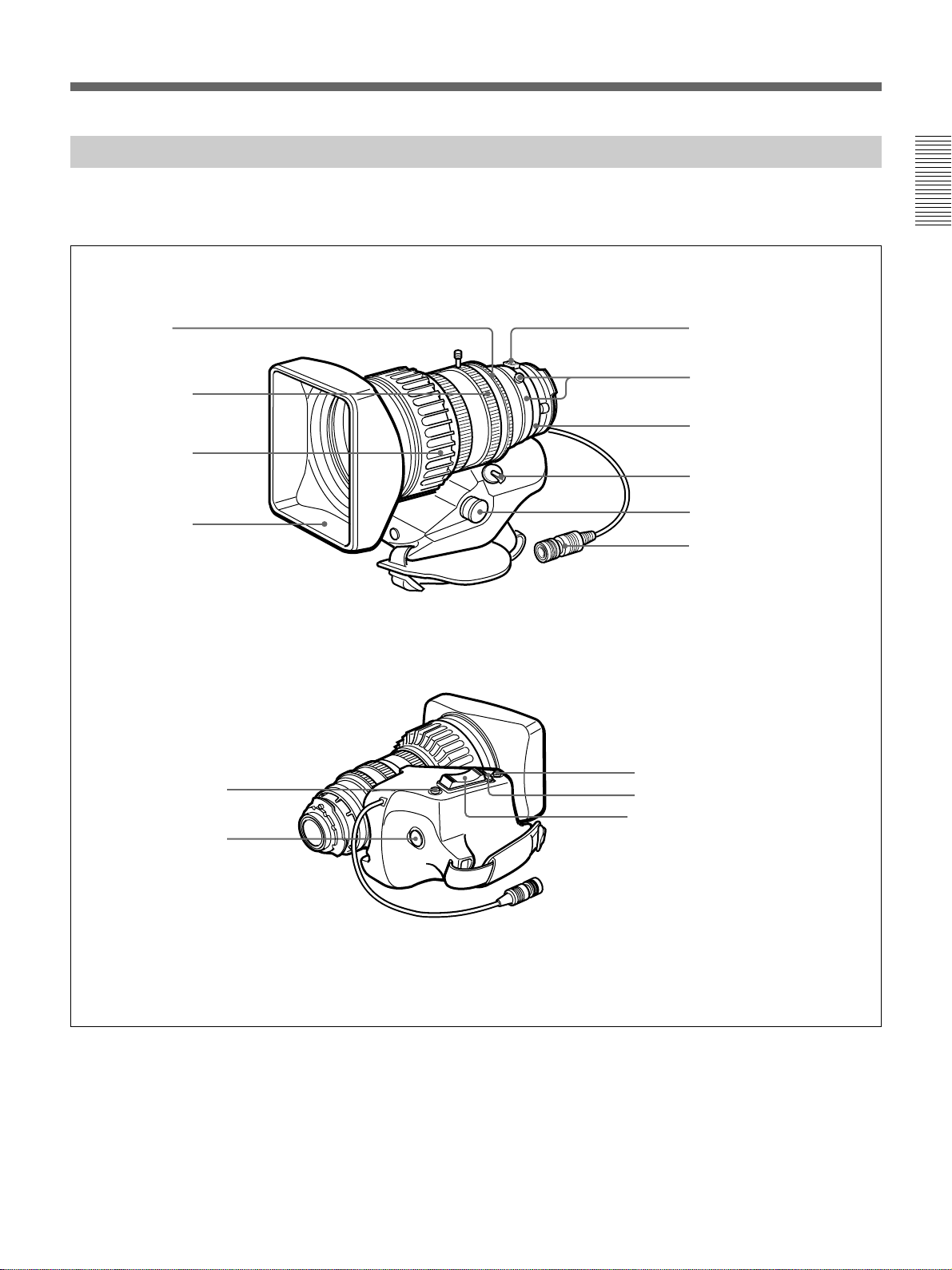
VCL-918BY Zoom Lens (not supplied)
When using a lens other than VCL-918BY, see page 121
(“Designating the lens”).
Chapter 1 Overview
1 Iris ring
2 Zoom ring
3 Focus ring
4 Lens hood
qa RET button
qs VTR button
!™
!£
5 M button
6 F.B adjustment ring
and F.B fixing screw
7 MACRO ring
8 ZOOM selector
9 Zoom remote control
connector
0 Lens connector
qd Instant automatic iris adjustment
!¢
button
!∞
qf IRIS selector
!§
qg Motorized zoom lever
Chapter 1 Overview 27
Page 28

Location and Function of Parts
1 Iris ring
For manual iris control, set the IRIS selector to the
“M” position, and turn this ring.
2 Zoom ring
Chapter 1 Overview
For direct manual zoom control, set the ZOOM
selector to the “MANU.” position, and turn this ring.
3 Focus ring
Turn this ring to focus the lens on the subject.
4 Lens hood
5 M (close-up) button
For close-up work, turn the MACRO ring while
holding this button down. (See page 121.)
6 F.B (flange focal length) adjustment ring and
F.B (flange focal length) fixing knob
F.B (flange focal length) adjustment ring : To
adjust the flange focal length, loosen the F.B
fixing knob, then turn the ring.(See page 119.)
F.B (flange focal length) fixing knob: Fixes the F.B
adjustment ring.
7 MACRO (close-up) ring
For close-up, turn this ring while holding the M button
down. (See page 121.)
8 ZOOM selector
This selects the mode of zoom operation.
SERVO: power zoom
MANU. (manual): manual zoom
9 Zoom remote control connector (8-pin)
Connect the optional LO-26 lens remote control unit
for remote control of zooming.
When connecting the optional lens cable (Sony
product number: 1-790-779-11) to this connector, you
can control the zoom from the RM-VJ1 Remote
Control Unit (equipped with microphone and monitor).
(See page 41.)
0 Lens connector (12-pin)
Connect to the LENS connector (9 on page 24) of the
camcorder.
qa RET (return) button
This allows you to check the video signal as follows.
When the internal VCR is in recording pause mode,
press this button to review the last few seconds of the
recording in the viewfinder (recording review). When
an external VCR is connected, pressing this button
1)
connects the E-E video signal
from the external VCR
to the viewfinder while the internal VCR is recording
or no tape is inserted in the internal VCR.
For details, see “Playback — Checking Recorded Contents”
(page 61).
qs VTR button
This button starts and stops recording on the
VCR.Press it once to start recording, and once more to
stop.
qd Instant automatic iris adjustment button
While using manual iris control, press this button to
switch temporarily to the automatic iris control
setting.The automatic setting is maintained as long as
you hold the button down.
qf IRIS selector
This selects the mode of iris operation.(See page 14.)
A (automatic): automatic iris
M (manual): manual iris
qg Motorized zoom lever
Use this to carry out a power zoom. Pressing the lever
harder increases the zoom speed.
W end: zoom toward wide angle
T end: zoom toward telephoto
..........................................................................................................................................................................................................
1) E-E video signal: “electric-to-electric” video
signal.This is the input video signal which has passed
through internal electrical circuits, but has not been
converted to a magnetic signal.
28 Chapter 1 Overview
Page 29
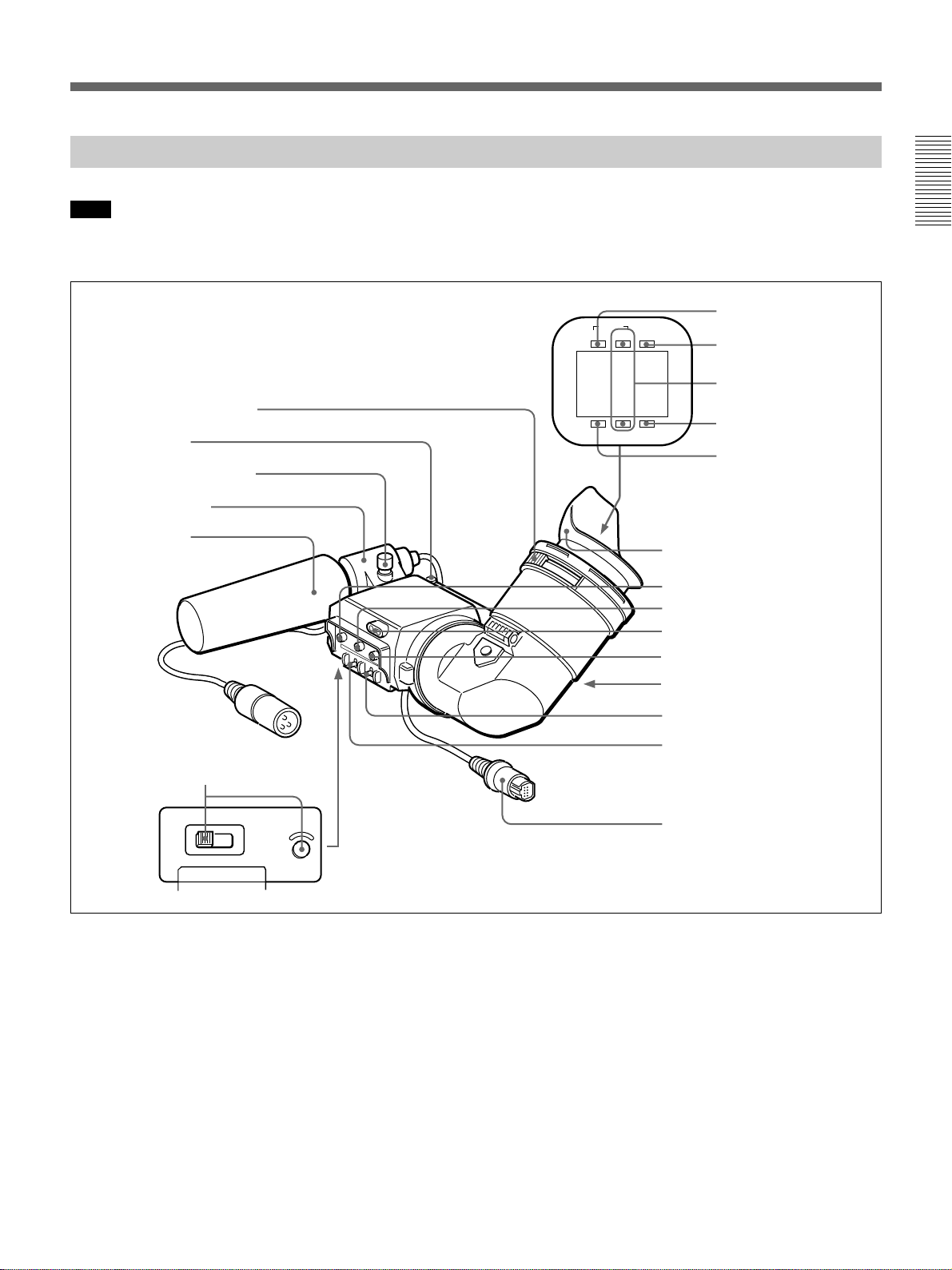
DXF-801/801CE Viewfinder
Note
You can switch the scan size of the DXF-801/801CE
1 Eyepiece focusing knob
2 Stopper
Microphone holding screw
Microphone holder
Microphone
in accordance with the aspect ratio selected on the
camera or camcorder.
TALLY
TAKE BATTREC
SHUTTER GAIN UP
9 PEAKING control
0 CONTRAST control
qa Tally lamp
qs BRIGHT control
4 TAKE/TALLY indicator
5 BATT indicator
6 REC/TALLY indicators
7 GAIN UP indicator
8 SHUTTER indicator
Eye cup
Chapter 1 Overview
3 LIGHT switch and light
HIGH LOW OFF
LIGHT
1 Eyepiece focusing knob
Turn this to adjust the viewfinder focus to match your
eyesight. (See page 118.)
2 Stopper
Lift up when detaching the viewfinder (See page 34).
3 LIGHT switch and light
The light lights the lens and the switch controls the
light as follows.
HIGH/LOW: Turn the light on and control the
brightness.
OFF: Turns the light off.
qd Eyepiece release catch
qf TALLY switch
qg DISPLAY switch
qh Viewfinder connector
4 TAKE/TALLY indicator (orange)
When using the ClipLink function while shooting, this
indicator lights when the TAKE button (6 on page
12) has been pressed to set a Mark IN point and goes
out when a Mark OUT point is set.
5 BATT (battery) indicator (red)
This indicates when the battery capacity is low.
Chapter 1 Overview 29
Page 30

Location and Function of Parts
6 REC/TALLY (recording/tally) indicators (red)
•From the time when you press the VTR button (9 on
page 12 and qs on page 28) on the lens (not
supplied) or camcorder, this flashes until recording
Chapter 1 Overview
starts, then stays on continuously during recording.
•This is also used to indicate a fault. (See page 127.)
•The lower indicator can be disabled by menu setting.
(See page 89.)
7 GAIN UP indicator (orange)
This lights when the gain is 3 dB or more.
8 SHUTTER indicator (red)
This lights when the SHUTTER switch (5 on page
12) is in the ON position. (If the EVS is selected, the
indicator will not light.)
9 PEAKING control
This adjusts the outline intensity of the viewfinder
image. (See page 118.)
0 CONTRAST control
This adjusts the contrast of the viewfinder image. (See
page 118.)
qg DISPLAY switch
Set this switch to OFF when you want to remove the
character data from the viewfinder and the monitor
connected to the MONITOR OUT connector.
However, items which are set to OFF in advanced
menu page 5 and page 6 are not displayed even when
this switch is set to ON.
qh Viewfinder connector (20-pin)
2
Connect this to the VF connector (
on page 12).
qa Tally lamp
When the TALLY switch qf is in the HIGH or LOW
position, this operates in the same way as the REC/
TALLY indicators 6.
qs BRIGHT (brightness) control
This adjusts the brightness of the viewfinder image.
(See page 118.)
qd Eyepiece release catch
To view the viewfinder screen directly, press this
catch, and hinge up the eyepiece.
qf TALLY switch
When using the Tally lamp qa, this switch controls it
as follows.
HIGH/LOW: Turn the light on and control the
brightness.
OFF: Turns the light off.
30 Chapter 1 Overview
Page 31

Inserting and Replacing the Lithium Battery
Chapter 2 Fitting and Connections
The camcorder uses a lithium battery to retain stored
data. When using the camcorder for the first time, be
sure to insert the supplied lithium battery
(CR2032). The camcorder will not operate correctly
without this lithium battery.
Lifetime of the lithium battery
When the lithium battery’s voltage falls, the lithium
backup battery warning
window. If this warning appears, replace the lithium
battery (CR2032) within three or four days.
The lithium battery has an average service life of about
two years, however operation with the optional DSBK-
301A in ClipLink mode will shorten the lifetime until
about one year.
appears in the display
Li
1 Turn the POWER switch on.
2 Press down the catch at the top
of the battery cover and open
the cover.
Inserting or replacing the lithium battery
Notes
•Carefully read the instructions for inserting and
replacing the lithium battery. Lithium batteries may
explode if misused.
•Use only CR2032 Lithium Batteries. Other types of
lithium batteries may come loose when the camcorder
is moved. If you have difficulty finding CR2032
Lithium Batteries, contact your Sony dealer.
2
Catch
Press and pull forward.
Chapter 2 Fitting and Connections
3 Take out the lithium battery.
4 Reverse step 3 to insert a
replacement lithium battery.
Make sure that the + symbol
on the battery is facing you.
5 Close the battery cover.
1 POWER switch
Press down and pull out toward you.
Lithium battery
LI
LITHIUM BATT
Battery cover
Chapter 2 Fitting and Connections 31
Page 32

Fitting the Lens
Note
Be sure to turn off the power before fitting the lens.
1 Remove the retaining rubber
which prevents the lens mount
from coming loose, then raise
the lens fixing lever, and
remove the lens mount cap.
Chapter 2 Fitting and Connections
Retaining rubber
2 With the lens fixing lever
turned fully counterclockwise,
push in the lens, aligning the
projection on the lens with the
cutout on the camcorder.
3 Supporting the lens, turn the
lens fixing lever fully
clockwise. Replace the
retaining rubber on the lens
mount.
Lens mount cap
Lens fixing lever
Align and push in.
32 Chapter 2 Fitting and Connections
Page 33

Fitting optional filters
Loosen the lens hood fixing knob to remove the lens
hood, then attach the filter.
Remove lens hood
Lens hood fixing
Filter (optional)
knob
Chapter 2 Fitting and Connections
Chapter 2 Fitting and Connections 33
Page 34

Using Accessories
Using the Viewfinder
Removing the viewfinder
1 Pull the viewfinder plug out of
the VF connector on the front.
Chapter 2 Fitting and Connections
2 Loosen the viewfinder left-to-
right position fixing ring, then
pulling up the retaining catch,
slide the viewfinder out.
VF connector
Retaining catch
Viewfinder left-to-right
position fixing ring
To fit the viewfinder
Reverse the removal procedure. (You need not hold
the retaining catch up.)
Left eye adaptor
By fitting a left eye adaptor, you can use the
camcorder with your left eye to the viewfinder.
Note
You cannot stow the camcorder with a left eye adaptor
attached in the carrying case.
For details, consult your Sony dealer.
34 Chapter 2 Fitting and Connections
Adjusting the viewfinder position
To adjust the viewfinder left-to-right position, loosen
the viewfinder left-to-right fixing ring, and to adjust
the front-to-back position loosen the viewfinder frontto-back position locking knob.
Viewfinder front-to-back
position locking knob
Viewfinder left-to-right
position fixing ring
Page 35

Fitting the 4-inch/5-inch Electronic Viewfinder
You can fit the optional DXF-51 (5-inch)/DXF-41 (4-inch) Electronic Viewfinder. To fit, the following parts are
required.
Required parts to fit
Name Part No.
Accessory Shoe Kit A-8274-968-B
Adaptor cable (8-pin y 20-pin) 1-783-665-11
(DXF-41 only)
Shoe*
Stopper
screw*
VF Cable
Fixing ring
Guide
For details, consult your Sony dealer.
How to fit
Remove the cover of the grip and attach the shoe and
stopper screw (accessory shoe kit).
Adaptor cable (8-pin y 20-pin)
• Supplied with the Accessory Shoe Kit
20-pin
Fitting to a Tripod
First fit the VCT-U14 Tripod Adaptor to the tripod, then mount the camcorder on the tripod adaptor.
Note
After removing the camcorder, if the tripod adaptor pin
has not returned to its original position, hold down the
red button and move the lever in the direction of the
arrow to return the pin to its original position. It is not
possible to mount a camcorder with the pin left out.
8-pin
Chapter 2 Fitting and Connections
VCT-U14 Tripod Adaptor
Side the camcorder forward
along the slot, until it clicks
firmly into place.
Removal
Pin
Tripod
Hold down the red button
and pull the lever in the
direction of the arrow.
Chapter 2 Fitting and Connections 35
Page 36

Using Accessories
Using an Optional Microphone
To use a long microphone such as the optional ECM-670/672, fit an optional CAC-12 Microphone Holder to the
camcorder, then mount the microphone in this holder.
Fitting the optional CAC-12 Microphone Holder
Remove the two retaining screws (M3 × 8) for the
optional microphone holder, then use these screws to
Chapter 2 Fitting and Connections
CAC-12
Fitting an optional microphone
Use the following procedure to attach an optional
ECM-670 Microphone.
attach the CAC-12 Microphone Holder.
Screws removed from the
camcorder
Loosen the screw of the CAC-12
Microphone Holder, then open the
holder and replace the microphone
adaptor with the one supplied with
the ECM-670 Microphone.
Fitting optional microphones (operable with a
48 V supply) other than the ECM-670
Use the same fitting procedure as for the ECM-670,
but note the following differences with respect to the
microphone adaptor.
36 Chapter 2 Fitting and Connections
Microphone adaptor
ECM-672: no microphone adaptor required.
Slender microphones (19 mm (
3
/4 inch) diameter):
use the microphone adaptor supplied with the
CAC-12.
Page 37

Using a Video Light
For the DSR-500WSL/500WSPL, you can use the
Anton Bauer Ultralight 2 or equivalent. Use a video
light powered by 12 V with maximum power
consumption of 30 W.
•If you connect the video light to the video light
connector on the DSR-500WSL/500WSPL (page 23)
and set the LIGHT switch to AUTO (page 13), you
can turn the light on and off automatically as you
start and stop VCR operation.
•The output of the video light connector on the DSR500WSL/500WSPL is controlled to 12 V even when
the camcorder is supplied with 12 V or more power
(through the DC IN connector or battery pack). The
brightness or color temperature of the light will not
change according to voltage increase.
Notes
•Do not use the video light with power consumption of
over 30 W.
•The brightness or color temperature of the light will
change when the supplied voltage is under 12 V
(through the DC IN connector or the battery pack).
To fit the video light
Fit the video light to the camcorder grip and connect
the video light cable to the video light connector.
When using a video light with a long cable
You can pass a part of the cable through the camcorder
grip.
Chapter 2 Fitting and Connections
1 Remove the cover of the camcorder
grip and break off projection A (see
the figure).
2 Pass the cable through the grip as
shown in the figure and replace the
cover.
When using equipment other than the
camcorder for power supply
Break off projections A and B on the camcorder. (See
step 1 of the previous section “When using a video
light with a long cable”.) Insert the cable into the grip
from the front hole and take out from the rear hole as
shown in the figure.
Projection B
Projection A
Chapter 2 Fitting and Connections 37
Page 38

Using Accessories
Fitting the Shoulder Strap
This section describes the procedure for fitting the supplied shoulder strap to the camcorder.
1 Fit one of the clips to a
shoulder strap fitting.
Pull up the strap to
lock the fitting.
Chapter 2 Fitting and Connections
2 Fit the other clip to the
shoulder strap fitting on the
other side of the grip in the
same way.
Removing the shoulder strap
Open the cover of the clip and move
the clip downwards to release it
from the fitting.
38 Chapter 2 Fitting and Connections
Page 39

Connecting to Audio System
The DSR-500WSL/500WSPL is able to record sound not only from the microphone attached but also from a
wireless microphone or an external audio system.
Using a wireless microphone system
You can use the wireless microphone system
including a WRT-810A/830A UHF Wireless
Microphone and a WRR-810A/855A/860A UHF
synthesized tuner to record sound.
To connect a WRR-855A
1 Open the cover of the WRR
connector.
2 Insert the WRP-855A into the
CA-WR855.
For details on using the wireless microphone system, see the
operating instructions for the microphone and tuner.
Chapter 2 Fitting and Connections
WRR connector
WRR
Fasten the screws (supplied with
the WRR-855A).
3 Fit the attachment plate on the
rear side of the CA-WR855 to
the V-groove on the battery
attachment interface, and then
slide the CA-WR855 down
until it connects to the WRR
connector.
4 Set one of the AUDIO IN (CH-
1/CH-2) switches to WRR.
CA-WR855
Chapter 2 Fitting and Connections 39
Page 40

Using Accessories
To connect a WRR-810A/860A
Attach the WRR tuner fitting (not supplied) (Part No.
A-8278-057-A) to the rear of the camcorder as shown
in the following figure.
2,3
4
Chapter 2 Fitting and Connections
1 Pass a screwdriver through the holes and tighten
the screws.
2 Loosen the adjustment screws.
3 Adjust the metal fitting position for a battery
pack to be attached, and tighten the adjustment
screws to fix its position.
Using an external audio system
Connect an audio mixer or other external audio system
component to the AUDIO IN CH-1/CH-2 connector as
shown below.
5
14
WRR-810A/860A
4 Attach the holder kit (two fittings and four screws,
supplied with the tuner) to the WRR tuner fitting
(one for the upper position and the other for the
lower position).
5 Mount the tuner on the WRR tuner fitting.
For details about the WRR tuner fitting (Part No. A-8278057-A), contact your Sony dealer.
40 Chapter 2 Fitting and Connections
AUDIO IN (CH-1/CH-2) switches: Set to REAR.
CH-1
Input selection switch: Set to LINE.
LINE MIC
AUDIO IN
CH-1/CH-2
AUDIO IN
FRONT
VJ MIC
WRR
REAR
CH-2
+48V ON
To audio mixer, etc.
Page 41

Using the Optional RM-VJ1 Remote Control Unit (Equipped With Microphone And Monitor)
You can control the camcorder while watching the
image on the LCD screen of the Remote Control Unit
if you connect the RM-VJ1 Remote Control Unit to the
camcorder.
RM-VJ1 Remote
DSR-500WSL/500WSPL
control unit (equipped
with microphone and
monitor)
When using conventional lens
When using conventional lens, such as VCL-918BY,
you can control the zoom if you use the optional lens
cable (Sony product number: 1-790-779-11). For
details on the cable, consult your Sony dealer.
The connection for controlling the zoom when using conventional lens
REMOTE1
Lens cable
(1-790-779-11)
Chapter 2 Fitting and Connections
REMOTE 2
CCA-7-7A cable
Note
Be sure to use the CCA-7-7A Cable only when
connecting the RM-VJ1.
When using lens designed for the power
zoom and focus
Use the following lens when controlling the zoom and
focus from the RM-VJ1:
Fujinon: A19X8.7 BRD-S28
A19X8.7 BERD-S28 (with the extender)
A19X8.7 BRRD-S28 (with the ratio
converter)
Canon: YJ18X9B KAS-SS12
YJ18X9B IAS-SS12 (with the extender)
RM-VJ1
Remote
control unit
(equipped
with
microphone
and monitor)
REMOTE2
Remote control connector
(8-pin) for controlling the
zoom on the bottom of the
lens grip
For details on these lens or other lens designated for
the power zoom and focus, consult Fujinon or Canon
dealer.
Chapter 2 Fitting and Connections 41
Page 42

Using Accessories
Using the RM-LG1 Remote Control Unit
You can control the camcorder using the supplied RM-LG1 Remote Control Unit.
Location and Function of Parts
1 Cable with mini-plug
Chapter 2 Fitting and Connections
1
2
1 Cable with mini-plug
Connect to the REMOTE connector 1 (5 on page 23)
on the DSR-500WSL/500WSPL.
2 Switches 1 and 2
3 Switch name
displays
5 Cable clamp
4 Velcro
groove
4 Velcro
When using the unit on the panning rod of the tripod,
this is used to attach the unit to the panning rod
mounting bracket (supplied with RM-LG1).
5 Cable clamp groove
When the cable 1 is passed underneath the unit, the
cable can be placed in this groove.
Attaching the RM-LG1
Use the binding ties and panning rod mounting bracket
to attach the unit to a panning rod.
Panning rod mounting bracket
Velcro
2 Switches 1 and 2
You can assign functions to these switches using the
advanced menu page 3 (see page 88) of the DSR500WSL/500WSPL.
Each can be used as the following types of switch:
VTR switch, MARK switch, CUE switch, or NG
switch.
At the shipping of the DSR-500WSL/500WSPL,
switch 1 is set as the VTR switch and switch 2 is set as
the MARK switch.
For information about the advanced menu and function of
each switch, see “Location and Function of Parts” on page
12 and “Viewfinder Advanced Menu” on page 86.
3 Switch name displays
Stickers (supplied with RM-LG1) can be attached here
to indicate which functions are assigned to the
switches 1 and 2 2.
Binding ties
Panning rod
Removing the RM-LG1
Lift up the tab to loosen the binding ties.
42 Chapter 2 Fitting and Connections
Page 43

Using the Optional LC-DS500 Carrying Case
For details on using the carrying case, refer to the instruction manual supplied with the carrying case.
For detail on the time that the carrying case will appear on the market, consult your Sony dealer.
Using the Optional LC-DS300SFT Soft Carrying Case
For details on using the soft carrying case, refer to the instruction manual supplied with the soft carrying case.
Chapter 2 Fitting and Connections
Chapter 2 Fitting and Connections 43
Page 44

Connections
Connecting a Number of Camcorders
When using two or more synchronized camcorders,
connect an external sync signal to the GEN LOCK IN
connector, supplying a VBS or BS signal. The
camcorder will then operate synchronized to this
signal.
You can adjust the synchronization using the basic
menu. (See page 81.)
Chapter 2 Fitting and Connections
Example 1: Camcorder 2 synchronized
to the signal from camcorder 1
DSR-500WSL/500WSPL
Camcorder 1
VTR
VIDEO OUT
CCZ-A Camera Cable
To camera
connector
Note
When you fit the optional DSBK-501/501P, set the
VIDEO IN to CAM using the basic menu page 4. (See
page 81.)
BNC cable
Camcorder 2
Portable VCR
GEN LOCK IN
To video input
connector
BNC cable
DSR-500WSL/500WSPL
VIDEO OUT
Example 2: Camcorders 1 and 2 synchronized to the signal from a special effects unit or similar
Camcorder 1
Video input connector
Sync signal output
connector
Special effects
unit or similar
Video input connector BNC cable
Sync signal output
connector
BNC cable
BNC cable
BNC cable
VIDEO OUT
GEN LOCK IN
Camcorder 2
VIDEO OUT
GEN LOCK IN
DSR-500WSL/500WSPL
DSR-500WSL/500WSPL
44 Chapter 2 Fitting and Connections
Page 45

Connecting the DSR-70/70P Digital Videocassette Recorder (Optional DSBK-140 Is Required)
You can do cut editing and digital dubbing when connecting the DSR-70/70P with fitting the optional DSBK-140,
using an i.LINK cable (DV connecting cable).
DSR-70/70P Digital
Videocassette Recorder
DSR-500WSL/500WSPL
Chapter 2 Fitting and Connections
DV OUT
i.LINK cable (DV connecting cable)
Notes
•The camcorder does not support the noiseless
function of the various speed playback.
•The slow playback will be automatically released to
protect the tape if the slow playback lasts for about
one minute.
Connecting an External VCR
You can use a following external VCR connected to
the VTR connector (26-pin) or the DV OUT connector
for recording.
Connector
VTR connector
VTR connector
DV OUT
connector
VCR
BVW-50/50P/35/
35P (portable)
VO-8800/6800
(U-matic)
Digital
Videocassette
Recorder DSR20/20P/70/70P/
2000/2000P, etc.
Connecting cable
CCZ-A Camera
cable (max. length
10 m (33 ft.))
CCZQ-A Camera
cable (max. length
10 m (33 ft.))
i.LINK cable (DV
connecting cable)
(max. length
4.5 m (14 ft.))
DV IN
•When dubbing tapes using the DSR-70/70P, a
continuous recorded section of approximately five
seconds is required before the recording start point. It
is recommended to record beforehand color bars or a
similar signal at the start point of the source tape to
be dubbed on this unit.
Notes
•There is no power supply connection between the
camcorder and VCR. Provide separate power
supplies.
•The VTR connector always outputs the signals from
the camera (impossible to output the playback video
of the internal VCR), and disallows the CCU
connection.
•When no VCR is connected to the VTR connector
(26-pin), it does not supply signals.
Chapter 2 Fitting and Connections 45
Page 46

Power Supply
The following power supplies can be used with the
camcorder.
•BP-L40/L40A/L60/L60A/L90/L90A lithium-ion
battery pack
•NP-1B Ni-Cd Battery Pack (The DC-L1Battery
Adaptor is required.)
•BP-90A Ni-Cd Battery Pack (The DC-L90 Battery
Adaptor is required.)
Chapter 2 Fitting and Connections
Using a BP-L40/L40A/L60/L60A/L90/L90A Battery Pack
With a battery pack, the camcorder will operate
continuously for the time shown below.
BP-L40/L40A: Approx. 70 minutes
BP-L60A: Approx. 140 minutes
BP-L90A: Approx. 230 minutes
Before use, charge the battery pack with a BC-L50/
L100/L100CE Battery Charger.
Notes on using the battery pack
•A warm battery pack may not be able to be fully
recharged.
•Even when fully charged, battery packs gradually
lose their charge naturally. Use the battery packs as
soon as possible after recharging.
•To prolong the life of battery packs, store them in a
cool place (about 20°C (68°F)), and charge in a place
with an ambient temperature between 10°C and 30°C
(50°F to 86°F).
•Before long-term storage, discharge the battery fully.
This extends the battery’s life.
•It is recommended that the BP-L40/L40A be used at
30 W or less. The specified capacity may not be
obtained if it is connected to the camcorder with
accessories which is operated at 30 W or higher,
especially when the ambient temperature is low.
•AC power (The AC-550/550CE, AC-DN1/DN2A or
CMA-8A/8ACE AC Adaptor is required.)
Alternatively, you can make combined use of internal
and external batteries, by mounting one of the above
batteries as an internal battery and connecting an
external battery that can be a BP-90A contained in a
DC-210 Battery Adaptor and connected to the DC IN
connector of the camcorder.
•At low temperatures, the usable time of battery packs
decreases. When the ambient temperature is 0°C
(32°F), usable time decreases by about 10%.
(However, the usable time is affected by the power
consumption of the connected camcorder and the
usage status of the battery packs.) The usable time of
battery packs increases if they are warmed to the
room temperature (about 20°C (68°F)) before use at
low temperatures.
•If you use the BP-L40/L40A at temperatures of 0°C
(32°F) or below, when power consumption of the
camcorder and accessories is 40 W or higher (due to
using a video light, for example), power may break
after a short time (a few minutes). To increase the
usable time, store the BP-L40/L40A in a warm place
and power on the connected camcorder before the
BP-L40/L40A cools down.
•Compared to the BP-L40/L40A, the BP-L60/L60A/
L90/L90A offer better performance at low
temperatures. The BP-L60/L60A/L90/L90A are
recommended for use at low temperatures.
•Carrying a spare battery pack is recommended.
The BP-L40/L40A/L60/L60A/L90/L90A is free from
memory effect. There is no need to discharge it fully
before recharging.
Attaching the battery pack
1 Press the battery pack against
the rear of the camcorder,
aligning the side line of the
battery pack with the line on
the camcorder.
46 Chapter 2 Fitting and Connections
LOCK
BP-L40/L40A/L60/L60A/L90/L90A
Align these lines.
Page 47

2 Slide the battery pack down
until its “LOCK” arrow points
at the matching line on the
camcorder.
Detaching the battery pack
Holding the button in, pull the
LOCK
battery pack up.
Avoiding breaks in operation due to dead
batteries
Matching line on the
camcorder
LOCK
“LOCK” arrow
Continuous operation when operating with
only an internal battery pack
First, connect a fully charged external battery to the
DC IN connector, then change the internal battery.
Notes
•Whenever an internal battery pack is loaded and an
external battery is connected to the DC IN connector,
the external battery is always used as the power
source.
•There may be some noise on the video or audio signal
at the instant the power sources are switched.
Chapter 2 Fitting and Connections
If you use both an internal battery pack and an external
battery connected to the DC IN connector at the same
time, you can avoid breaks in operation due to the dead
batteries.
When the external battery begins to fail and
an internal battery pack is also used
Remove the DC output cable of the external battery
from the DC IN connector. The power source will
switch to the internal battery pack.
When the external battery begins to fail and
an internal battery pack is not used
First load the camcorder with a fully charged internal
battery pack, then remove the DC output cable of the
external battery from the DC IN connector. The power
source will switch to the internal battery pack. To use
an external battery again, connect a fully charged
external battery to the DC IN connector before
unloading the internal battery pack. The power source
will switch to the external battery.
Chapter 2 Fitting and Connections 47
Page 48

Power Supply
Using an AC Adaptor
Using a CMA-8A/8ACE AC Adaptor
Connect the camcorder to the AC power supply as
shown in the following figure, and turn the POWER
switch of the CMA-8A/8ACE to ON.
Chapter 2 Fitting and Connections
LOCK
DC IN
POWER switch: ON
CCQX-3 cable
To AC power source
CMA-8A/8ACE
AC Adaptor
Using the Anton Bauer Intelligent Battery System
You can equip the camcorder with a special battery
mount which the Anton Bauer Corporation has
developed for its Intelligent Battery System and
Ultralight System.
When the camcorder is used with an Anton Bauer
Digital Magnum series battery, the remaining battery
capacity is shown numerically in the viewfinder
display.
Contact your Sony dealer for more information.
CAMERA/CCU
Using an AC-DN1/DN2A AC Adaptor
Mount the AC-DN1/DN2A on the camcorder in the
same way as a battery, then connect to the AC power
source.
To AC power
source
Note
When power consumption of the camcorder and
accessories is 38 W or higher, use the AC-DN2A AC
adaptor (lower than 150 W).
48 Chapter 2 Fitting and Connections
Page 49

Basic Procedure for Shooting
RET button
Focusing ring
ZEBRA button
POWER switch
FILTER control
VTR button
Chapter 3 Shooting
Note
Noise may appear in the EZ mode if the FILTER
control is set to 2 or 4, and iris is set to fully open. In
such case: when the FILTER control is set to 4, set it
to 2; when set to 2, set it to 3.
3 Check the switch settings on the camcorder. (See
pages 12 to 26).
If there is not sufficient time to check the
camcorder settings, you can use “easy mode” by
setting the EZ MODE button ON. The camcorder
is automatically adjusted to standard settings, and
the iris and the white balance are adjusted
automatically. (See page 91.)
VTRET40.0.2corder se2.89 -12. 1 Tstmen1 118.)
4 Check the settings in the basic menu (page 80) and
advanced menu. (page 86.)
5 Check the lens settings (pages 32 and 33) and
flange focal length adjustment. (page 119.)
6 Adjust the eyepiece focus, and the contrast and
brightness of the viewfinder image. (page 118.)
Chapter 3 Shooting 49
Page 50

Basic Procedure for Shooting
7 Check the sound system settings.
•Microphone connections
•Settings on the VCR section
8 If required, switch on the center marker and/or
safety zone (basic menu page 6 and advanced
menu page 4) and zebra pattern (ZEBRA button) in
the viewfinder image.
9 Adjust the white balance (page 112) and black
balance (page 115).
10Turn the focusing ring so that the subject is
sharply in focus.
It may be convenient to use the EZ FOCUS button
for the “easy focus” function. (See page 13.)
Chapter 3 Shooting
11Set up the VCR section according to your shooting
objectives, then start recording with the VTR
button.
•During recording, the REC/TALLY indicator(s)
in the viewfinder light(s), and “REC” appears on
the viewfinder screen.
•Depending on the setting of the REC TIME
switch (see page 21), you can display the total
recording time or the length of the current cut on
the viewfinder screen.
•You can use the AUDIO LEVEL knob on the
right side to manually adjust the channel 1 audio
level. To do this, you must first set up the VCR
section to enable manual adjustment of the audio
recording level. (See page 20.)
Using DynaLatitude Function
This function enables detailed adjustment of contrast
control in each pixel in accordance with a histogram of
luminance signal levels.
If use this function, the camcorder automatically
adjusts contrast control by detecting luminance levels
of each subject.
DL OFF
However, if a subject moves in shooting, the
brightness of the subject may be changed; noise on the
black portion may increase depending on subjects.
For turning on/off the function, see page 88, and for
the effect level, see page 81.
DL ON
12To pause recording, press the VTR button again.
50 Chapter 3 Shooting
Page 51

Recording
Cassettes for the DSR-500WSL/ 500WSPL
The DSR-500WSL/500WSPL can use standard-size
and mini-size DVCAM and DV series metal tape
cassettes. (To ensure high-quality playback, editing,
and storage of recorded contents, we recommend using
highly reliable DVCAM cassettes).
The following table lists the cassettes that can be used
in the DSR-500WSL/500WSPL.
Model name Size
PDV-64ME/64MEM/94ME/124ME/ Standard size
124MEM/184ME/184MEM
PDVM-12ME/22ME/32ME/32MEM/ Mini size
40ME/40MEM
The numbers in the model names show maximum
recording/playback time (minutes) for each model. For
example, the maximum recording/playback time of the
PDV-184ME is 184 minutes.
Notes
•If you insert an incorrect type of cassette, it will be
automatically ejected.
•When using a DV cassette, the maximum recording
time is reduced to two-thirds of the time indicated on
the cassette. For example, up to 40 minutes of
recording can be done on a 60-minute DV cassette.
DVCAM cassettes
For details of ClipLink log data, see “ClipLink Shooting”
(page 68).
Notes on using cassettes
•Before storing the cassette, rewind the tape to the
beginning and be sure to put the cassette in its storage
case, preferably on end instead of flat on its side. The
storage case of a DVCAM cassette is specially
designed to eusure a long-period storage of the tape.
Storing a cassette in any other condition (not
rewound, out of its case, etc.) may cause the video
and audio contents to become damaged over time.
•If the cassette memory connector (contact point)
becomes dirty, connection problems may occur and
cause a loss of functions. Remove away any dust or
dirt from this area before using the cassette.
•If the cassette is dropped on the floor or otherwise
receives a hard impact, the tape may become
slackened and may not record and or play back
correctly. For instructions on removing tape slack,
see next page.
•Follow the instructions on page 53 to insert a
cassette, or the camcorder may be damaged.
Preventing accidental erasure
Set the REC/SAVE switch to SAVE to prevent
accidental erasure of recorded contents.
Chapter 3 Shooting
The following figure illustrates the DVCAM cassette’s
appearance.
Standard size
Mini size
Cassette memory
REC/SAVE switch
For ClipLink shooting, a DVCAM cassette including
“cassette memory” is necessary. In the cassette
memory, data required for editing the recorded video
(ClipLink log data) is stored. The DSR-500WSL/
500WSPL can record or play back the cassettes with
cassette memory of 16 Kbits or less.
REC/SAVE switch
Set to SAVE
REC
SAVE
If you insert a cassette into the camcorder when this
switch is set to SAVE, the camcorder will not record
when you press the VTR button.
To enable recording
Set the REC/SAVE switch back to REC.
Chapter 3 Shooting 51
Page 52

Recording
Checking the tape for slack
Turn the reel gently in the direction shown by the
arrow. If the reel does not move, there is no slack.
Insert the cassette into the cassette holder, close the
cassette holder, and after about 10 seconds take it out.
Recording on the Internal VCR
Chapter 3 Shooting
This section describes basic recording operations using
the internal VCR.
Notes
•When you will not perform ClipLink shooting, set the
ClipLink function to oFF in the VCR menu. (See
page 109 for menu setting and see page 68 for details
of ClipLink shooting.)
•Before shooting, mount or connect any required
equipment or accessories and check the power
supply. (See Chapter 2 “Fitting and Connections”.)
Also, it is desireable to make sure for problems in
camcorder’s internal operations using the auto-check
function. (See “Menu 210 Using Auto-Check
Function” on page 107.)
See page 53 on how to insert a cassette.
Paper clip, etc.
Reel
•When using a tape recorded by the DSR-500WSL/
500WSPL to transfer digital (video/audio/time code)
signals at four times normal speed from the DSR-85/
85P Digital Videocassette Recorder to the ES-7
EditStation for editing purposes, there must be about
at least 40 seconds of recording on the tape before the
IN point. To perform editing without problems, it is
recommended that you pre-record at least 40
seconds of color bar signals at the beginning of the
tape.
•When dubbing tapes using the DSR-70/70P, a
continuous recorded section of approximately five
seconds is required before the recording start point. It
is recommended to record beforehand color bars or a
similar signal at the start point of the source tape to
be dubbed on this unit.
1
52 Chapter 3 Shooting
4
31
2
Page 53

1 Set the POWER switch to ON and check the
following items in the display window.
Item to check
How is the battery? BATT E [xxxxxx] F: The battery is fully charged.
Has the lithium battery
been inserted and is it
charged?
Is there a condensation
problem?
2 Press the EJECT button to open the cassette
Indication and steps
If two or fewer marks x appear and the indication is blinking,
replace the battery.
Make sure that the
If it is shown, replace the lithium battery.
Make sure that the “HUMID” indication is not shown in the
display window. If it is shown, do not use the equipment until
the “HUMID” indication disappears.
is not shown in the display window.
Li
Inserting a mini-size cassette
holder, and insert the cassette.
Make sure that the cassette’s REC/SAVE switch is
set to REC, then check for tape slack before
loading the cassette.
For details on handling cassettes, see “Cassettes for the
DSR-500WSL/500WSPL” on page 51.
Inserting a standard-size cassette
See also
“8 Display window” (page 16)
“Inserting and Replacing the
Lithium Battery” (page 31)
“Condensation” (page 128)
Stage
Chapter 3 Shooting
PUSH
PUSH
Indication “PUSH”
Cassette holder window
Insert the cassette with the cassette window (on the front)
facing outward.
Indication “PUSH”
Cassette holder window
Guides
Mini-size cassette
match marks
Lock
Insert the cassette with the cassette window (on the front) facing
outward. Push the cassette between the both guides along the
stage until it goes under the lock.
Press on “PUSH” on the cassette holder solidly to
close the holder.
(Continued)
Chapter 3 Shooting 53
Page 54

Recording
Notes
•Turn the power on and then insert or eject the
cassette.
•When inserting a mini-size cassette, confirm the
cassette is under the lock (see the figure on the
previous page), and then close the cassette holder. If
the cassette is not inserted fully under the lock, a
stopper will prevent the cassette holder from closing
when you press down on it.
•Internal parts of the camcorder may become bent or
otherwise damaged if you attempt to close the
cassette holder after inserting a mini-size cassette in
the wrong direction (such as with the cassette turned
backside front so the reel holes face the cassette
holder window or with the cassette turned sideways
so that a short side enters first).
CL
•If
Chapter 3 Shooting
appears in the display window when the
cassette is loaded, it means that data has already been
recorded into the cassette memory. If you record
under this condition whether the ClipLink function is
available or not, the existing cassette memory data
will be overwritten. To avoid this, insert a new
cassette.
•After inserting the cassette, close the cassette holder
solidly by pressing on the “PUSH” indication on the
holder. Unless the cassette holder is closed solidly,
the tape will not be loaded and the tape operation
buttons will not function. If you find the tape
operation buttons inoperable, press on the “PUSH”
indication again to make sure that the cassette holder
is solidly closed.
PUSH
Do not insert cassette sideways.
3 Make the switch settings shown in the figure
below.
REC TIME SKIN DTL EXT VTR
TTL
DUR
OFF
TTL RESET
HYPER
GAIN
FILE
ON
STD
OFF
SET
SETUP
ON
COMPONENT.
OFF
PARALLEL
FRONT MIC
LOW CUT
ON
OFF
INT ONLY
EXT ONLY
OUTPUT
VBS
Y/C
VTR
TRIGGER
WARNING
RESET
(MENU SET)
MENU
MONITOR SELECT
MIX
EXT
ClipLink
CONTINUE
PB DATE NDF EXT-LK HOLD
H MIN SEC FRM
CLIP
TAPE
BATT
EF
DIAG
RF SERVO HUMID SLACK
ADVANCE SHIFT
PRESET
F-RUN
DATE/TIME
REGEN
F-RUN
R-RUN
MONITOR OUT
CHARACTER
ON
OFF
SET
CH-1
CH-2
TC mode switch 2: F-RUN or R-RUN
TC mode switch 1: PRESET
IP
CL
CONT
DVCAM
Li
LITHIUM BATT
OVER OVER
1dB2
0
-12
-20
-30
-40
∞
-
F
8
32k
F
8
48k
AUDIO LEVEL
AUDIO SELECT
CH-1
COUNTER
AUTO
MAN
AUDIO IN
FRONT
VJ MIC
WRR
REAR
U-BIT
b)
LIGHT
ON
OFF
DISPLAY
TC
CH-2
PUSH
Do not insert cassette backside front.
a) When one of these switches is set to MAN, the
recording volume can be manually adjusted. For
details, see “Manually adjusting audio recording
level” on page 55.
b) For details, see “Setting the Time Code Value” on
page 64.
AUDIO SELECT
(CH-1/CH-2)
switches: AUTO
b)
a)
54 Chapter 3 Shooting
Page 55

4 Display menu 212 and select the audio recording
mode (two-channel recording mode or fourchannel recording mode).
For menu operation, see “Menu 212 Selecting Audio
Recording Mode ” (page 109).
Recording begins when the TALLY indicator stays
lit after blinking for a moment.
During recording, the tape transport buttons
(EJECT, REW, F FWD, PLAY, and STOP) cannot
be used.
Note
One of the following warning indications appears
in the display area when you change the audio
mode setting during recording pause.
Warning indication
Fs 48k (flashes four
times per second)
Fs 32k (flashes four
times per second)
Status
Attempting to switch from 32-kHz
mode (four-channel mode) to 48-kHz
mode (two-channel mode).
Attempting to switch from 48-kHz
mode (two-channel mode) to 32-kHz
mode (four-channel mode).
The recordings at switching points prevent editing.
Avoid changing the audio mode once you have
started recording.
5 Set up the camcorder to suit your recording
objectives, and press the VTR button on the
camcorder or lens.
Operation Step
To view image
being shot
• Look into the viewfinder.
• Connect a video monitor to the
MONITOR OUT connector, VIDEO
OUT connector, or S VIDEO OUT
connector.
To listen to audio
track being shot
Connect an earphone to the
EARPHONE connector
or listen to the audio from the
speaker.
To pause recording Press the VTR button on the
camcorder or lens.
For instructions on continuing to
record after a pause, see “Back
Space Editing” (page 58).
To stop recording
To remove the
cassette
Press the VTR button on the
camcorder or lens, then press the
STOP button.
With this state, it is impossible to start
back space editing.
Check that the power is on, then
press the EJECT button to open the
cassette holder and remove the
cassette. Close the cassette holder.
Chapter 3 Shooting
Manually adjusting audio recording level
1 In step 3 above (“Recording on the Internal
VCR”), set the AUDIO SELECT (CH-1/CH-2)
switches to MAN (see page 54).
REC TIME SKIN DTL EXT VTR
TTL
DUR
OFF
TTL RESET
HYPER
GAIN
FILE
ON
STD
OFF
SET
SETUP
ON
COMPONENT.
OFF
PARALLEL
FRONT MIC
LOW CUT
ON
OFF
TRIGGER
INT ONLY
EXT ONLY
OUTPUT
VBS
Y/C
VTR
WARNING
RESET
(MENU SET)
MONITOR SELECT
MIX
EXT
ClipLink
CONTINUE
MENU
CH-1
CH-2
ADVANCE SHIFT
PRESET
DATE/TIME
PB DATE NDF EXT-LK HOLD
H MIN SEC FRM
CLIP
TAPE
BATT
EF
DIAG
RF SERVO HUMID SLACK
REGEN
MONITOR OUT
CHARACTER
ON
OFF
F-RUN
F-RUN
R-RUN
2 While checking the audio level in the display
window, turn the AUDIO LEVEL (CH-1/CH-2)
knobs for the channel being used for microphone
or wireless microphone system connection (CH-1
or CH-2) so that the maximum audio level is under
0 dB.
32k
48k
AUDIO LEVEL
AUTO
AUDIO SELECT
CH-1
AUDIO IN
FRONT
VJ MIC
COUNTER
MAN
WRR
REAR
ON
OFF
DISPLAY
TC
U-BIT
CH-2
LIGHT
Audio level
indications
AUDIO LEVEL
(CH-1/CH-2)
knobs
SET
IP
CL
CONT
DVCAM
Li
LITHIUM BATT
OVER OVER
0
-12
-20
-30
-40
∞
-
F
8
1dB2
F
8
Chapter 3 Shooting 55
Page 56

Recording
When the battery is getting exhausted
When the battery is getting exhausted, the BATT
indication in the display window blinks once a second.
(see page 17.) Replace the battery with a charged
battery immediately.
If you continue to use the low battery, the BATT
indication will blink four times a second, and the
operation will stop.
For description of how to replace batteries, see “Power
Supply” on page 46.
Notes
•Turn the POWER switch OFF before replacing the
battery.
•If using two NP-1B batteries, be sure to replace both
Chapter 3 Shooting
batteries at the same time.
Recording an External Video Signals
When the optional DSBK-501/501P Analog
Composite Input Board is fitted to this camcorder, you
can record the external video signals.
Recording on an External VCR
Using the VTR Connector
Set the VTR TRIGGER switch in the following way.
(You can change the setting during recording.)
Simultaneous recording on the external and
internal VCR: PARALLEL
Recording on the external VCR: EXT ONLY
When the VTR TRIGGER switch is set to INT ONLY,
the camcorder controls only the internal VCR even if
an external VCR is connected.
For information about connectable VCRs, see “Connecting
an External VCR” (page 45).
Recording on the internal and external
VCRs simultaneously
(26-pin)
1 Set the switches as shown in the table below.
Switch
VTR TRIGGER switch
EXT VTR OUTPUT switch
Audio input level setting switch
on the connected VCR
Setting
PARALLEL
Set depending on the
connected VCR.
–20 dB
1 Connect the external video signals to the GEN
LOCK IN/VIDEO IN connector.
2 Set VIDEO IN to EXT using the basic menu page
4.
For details, see “Viewfinder Basic Menu” on page 81 .
3 Press the EJECT switch to open the cassette
holder, and insert the cassette.
4 Press the VTR button on the camcorder or lens.
The camcorder starts recording.
Notes
•If the external video signals include noise, such as
jitter, the camcorder may not record signals properly.
•When recording the external analog video signals,
signals are not output from the S VIDEO OUT
connector.
•Setup log data is not displayed when external analog
video signal are being recorded (see page 101.).
2 Put the external VCR in the recording pause mode.
3 Press the VTR button on the camcorder or lens.
The both VCRs start recording simultaneously.
To pause recording, press the VTR button on the
camcorder or lens again.
The both VCRs go into the recording paused state.
If either VCR comes to the end of tape during
recording, one VCR stops at the end of the tape,
and the other will continue recording.
To restart simultaneous recording, perform the
following.
When the internal VCR has run out of the tape:
Change the cassette, and press the VTR
button on the camcorder or lens.
When the external VCR has run out of the tape:
Change the cassette, and start recording with
the controls on the external VCR.
56 Chapter 3 Shooting
Page 57

Note
After replacing the cassette on the external VCR,
do not press the VTR button on the camcorder or
lens, as this will pause the internal VCR.
To operate either VCR during recording,
change the VTR TRIGGER switch setting. Both
VCRs continue recording at the time of switching.
Setting to INT ONLY: The camcorder can
operate only the internal VCR.
Setting to EXT ONLY: The camcorder can
operate only the external VCR. If you set
REC TIME to EXT in the advanced menu
page 4, you can change the total recording
time (TTL) from of the internal VCR to the
one of the external VCR.
Recording on the external VCR only
1 Set the VTR TRIGGER switch to EXT ONLY.
2 Use the controls on the external VCR to put it in
the recording paused state.
Recording on an External VCR Using the DV OUT Connector
You can record digital audio and video signals in the
DV format on an external VCR, using the DV OUT
connector.
For information about connectable VCR, see “Connecting
an External VCR” on page 45.
Note
When an external equipment, such as VCR, is
connected to the DV OUT connector, the ClipLink and
the audio fade-in/fade-out function during recording
will not work.
Chapter 3 Shooting
3 Press the VTR button on the camcorder or lens.
The external VCR starts recording.
To pause recording
Press the VTR button on the camcorder or lens again.
Using the viewfinder to see playback
pictures
For the internal VCR: Press the PLAY button.
For the external VCR: Press the RET button on the
lens when the internal VCR is in recording or no
cassette is inserted in the internal VCR. While
holding it down, you can see the return video from
the external VCR.
Chapter 3 Shooting 57
Page 58

Back Space Editing
This section describes the steps for recording several
scenes continuously.
1 Follow steps 1 to 5 (pages 53 to 55) in the
procedure “Recording on the Internal VCR” to
begin recording.
To continue the time code that has been recorded
on the tape, set the TC mode switch 2 to R-RUN in
step 3 (page 54).
For details of time codes, see “Setting the Time Code
Value” on page 64.
2 When you have finished recording a scene, press
the VTR button on the camcorder or lens.
This pauses the recording operation.
Chapter 3 Shooting
Note
Do not do any of the following before the next
scene is shot as it will interrupt the recording (the
recording will not be continuous).
•Remove the cassette.
•Transport the tape (play, rewind, fast forward).
•Press the STOP button.
•Replace the battery when the camcorder is
powered.
If there is a long period before shooting
the next scene
Once put the camcorder into recording pause mode, it
waits a certain (user-definable) period of time and then
automatically switches to standby-off mode. When the
camcorder is in standby-off mode, it takes time for the
recording to start after pressing the VTR button.
For details on setting the timeout value for automatic
switching to standby-off mode, see “Menu 207 Setting
Standby-On Period” on page 106.
Starting Back Space Editing at Any T ape Position
This section describes the steps for insert a new scene
at any desired position on the tape.
The following steps can also be used to restart
recording after an interruption has occurred.
1 Perform step 1 (page 53) in “Recording on the
Internal VCR”.
2 Insert the cassette containing the previous
recording.
3 When you are ready to shoot the next scene, press
the VTR button on the camcorder or lens again.
This restarts the recording operation.
4 Repeat steps 2 and 3 for each scene to be shot.
Operation Step
Restart an
interrupted recording
(see step 2 above)
Check the recorded
contents
Stop recording Press the VTR button on the
See next section “Starting Back
Space Editing at Any Tape Position”.
See “Checking the Recorded
Contents Immediately After Shooting
—Recording Review” on page 61.
camcorder or lens, then press the
STOP button.
3 Perform steps 3 and 4 (pages 54 and 55) in
“Recording on the Internal VCR”.
To continue from the last time code of the previous
recording, set TC mode switch 1 to REGEN.
For details about time codes, see “Setting the Time
Code Value” on page 64.
4 Press the PLAY button.
The recorded contents are displayed on the
viewfinder screen.
Operation at playback Step
Fast forward the tape Press the F FWD button.
Rewind the tape Press the REW button.
58 Chapter 3 Shooting
Page 59

STOP button
REW button
PLAY button
F FWD button
F FWD
EJECT
STOP
PLAYREW
5 Press the STOP button when the tape reaches the
position where the new recording will start (see the
figure above).
This stops the tape.
6 Press the RET button
on the lens.
•If the camcorder is left powered off for several hours.
•If the camcorder is subject to severe vibration while
powered off.
•If for any other reason the automatic recording
continuity function is unable to operate correctly.
•If the lithium battery (CR2032) is exhausted, or if no
lithium battery has been fitted.
Using the Edit Search Function While Back Space Editing
You can use the edit search function to find the desired
tape location when continuing to record from any other
location on the tape. Press and hold one of the EDIT
SEARCH buttons to activate the search playback
function for as long as you hold down it.
1 Turn on the power, then insert a cassette into the
VCR.
2 Perform steps 2 to 12 in “Basic Procedure for
Shooting” (pages 49 and 50).
Chapter 3 Shooting
This rewinds the tape slightly and runs it until the
continue point (specified by step 5), then sets the
camcorder to recording pause state.
7 Press the VTR button on the camcorder or lens.
This starts recording.
The edit search function enables you to search for the
continue position. For details, see next section.
Note
If you turn the POWER switch off during recording, or
when recording is paused, the camcorder automatically
goes through its shut-down sequence, then powers off.
When you next turn the POWER switch on, the
camcorder automatically finds the point at which
recording ended, and sets itself up so that you can
carry in with continuous recording. Note that this
operation takes several seconds: do not turn the
POWER switch off or replace the battery during this
interval, as the automatic recording continuity will be
lost.
Note also that the recording continuity is lost in the
following cases.
•If the POWER switch is turned on and off repeatedly.
3 Press and hold either of the EDIT SEARCH
buttons (REV or FWD).
REV button
FWD button
The tape is moved in reverse or forward search
mode for as long as you hold down the REV or
FWD button, and the image is shown in the
viewfinder.
(Continued)
Chapter 3 Shooting 59
Page 60

Back Space Editing
To change the playback speed
Press the REV or FWD button down firmly into
the inner position to make the tape move at the
faster speed. Press the button down lightly to
make the tape move at the slower speed.
Note
Do not shut off the power while using the edit
search function. The VCR may not be able to find
the continue point.
4 Release the REV or FWD button when you find
the tape location where you wish to continue
shooting.
The VCR enters recording pause mode.
5 Press the VTR button on the camcorder or the lens.
Chapter 3 Shooting
The VCR starts recording.
Using the Freeze Mix Function
The freeze mix function superimposes a freeze-frame
image of a previously recorded shot on the shooting
image displayed on the viewfinder screen.
You can use this function to easily frame a subject
within the same framework from a previous shot.
The following indication appears on the screen.
PLAY
m
FREEZE MIX(ONmPUSH)
EXIT MENU (YES
For details of the playback operation, see page 61.
m
PUSH)
4 Press the MENU dial when you see the image you
want to freeze.
The frozen playback image is displayed, mixed
with the shooting image, in monochrome. The
indication “FREEZE MIX ON” appears on the
screen.
FREEZE MIX ON
MIX OFF (YES
To release the freeze mix mode, press the MENU
dial again.
m
PUSH)
Note
When the camcorder is in EZ mode, the freeze mix
function is disabled. Press the EZ MODE button to
release the EZ mode beforehand. (See page 14.)
1 Connect a color monitor to the MONITOR OUT
connector and set the MONITOR OUT
CHARACTER switch to ON. (It is not necessary
to set the MONITOR OUT CHARACTER switch
to ON when using only the viewfinder for freeze
mix operation.)
2 Perform steps 2 to 10 from “Basic Procedure for
Shooting” (pages 49 and 50).
3 Play back the tape on which the image to be used
for framework alignment has been recorded, and
press the MENU switch to ON position.
60 Chapter 3 Shooting
To change the freeze-frame image
Press the PLAY button.
Use the tape transport buttons to find the desired
image and then perform step 4 again.
5 Once you have framed your subject, press the
MENU dial to cancel the freeze mix function.
6 Find the recording start point or insert a new
cassette for recording, then begin recording.
Notes
•If you use the tape transport buttons during back
space editing, the back space editing mode will be
stopped. When you were using the ClipLink function
at shooting, if you simply restart the recording you
will lose any ClipLink data that was recorded.
To avoid this, press the ClipLink CONTINUE button
before restarting recording.
•The signal is not output from the DV OUT connector
while using the freeze mix function.
Page 61

Playback — Checking Recorded Contents
Checking the Recorded Contents
Immediately After Shooting
— Recording Review
Immediately after shooting, you can use the recording
review function to automatically rewind and play back
the last 2 to 10 seconds of the recording to check the
recorded contents.
Performing recording review
With recording paused, press the RET button on the
lens.
Depending on how long you hold down the button, the
tape is automatically rewound over the last 2 to 10
seconds of the recording, and then this last part of the
recording is shown in the viewfinder. You can also
listen to the recorded sound via an earphone or the
speaker. After the recorded part is played back, the
camcorder is automatically returns to the pause state.
Notes
•During recording review, do not turn the POWER
switch off. The camcorder may not be able to find the
continue point.
•If you press the VTR button on the camcorder or lens
during recording review, the camcorder stops the
recording review and starts recording. In this case
(when ClipLink mode is oFF), it is impossible to start
back space editing.
Operation Step
Fast forward the tape Press the F FWD button.
Rewind the tape Press the REW button.
Stop the tape Press the STOP button.
Note
If two or more series of Index Pictures are recorded
separately on the tape, they may be played back at
back space editing points.
For details about Index Pictures, see “ClipLink Shooting”
(page 68).
EJECT
STOP button
REW button
STOP
PLAY button
F FWD button
F FWD
PLAYREW
Chapter 3 Shooting
Viewing Monochrome Playback in the Viewfinder
You can view a monochrome playback of the
recording in the viewfinder.
1 Turn the power on.
2 Load a cassette.
3 Press the PLAY button.
This starts playback, during which a monochrome
playback of the recording is shown in the
viewfinder.
Viewing Color Playback
Using a color television or color video monitor, you
can view a color playback (with no playback adaptors).
Connect a color television or color video monitor to
the MONITOR OUT connector or the S VIDEO OUT
connector.
See the previous section “Viewing Monochrome
Playback in the Viewfinder” for playback operation.
Chapter 3 Shooting 61
Page 62

Setting Time Values
The camcorder uses three types of time values: counter
values, time code values, and user bits.
The time value is displayed in the viewfinder screen
and in the display window.
Time value
indication
WARNING
RESET
(MENU SET)
PB DATE NDF EXT-LK HOLD
H MIN SEC FRM
CLIP
TAPE
BATT
EF
DIAG
RF SERVO HUMID SLACK
OVER OVER
0
-12
-20
IP
CL
CONT
-30
DVCAM
-40
Li
∞
-
F
8
32k
1dB2
F
8
48k
Use the DISPLAY switch to switch time value
indications.
Type of time value DISPLAY switch setting
Chapter 3 Shooting
Counter of tape transport time COUNTER
Time code TC
User bits U-BIT
Note
The time code and user bits cannot be displayed
properly if the tape does not have time code and/or
user bits recordings or if the time code was recorded
using a non-compatible method.
For details of the time value indication in the viewfinder, see
page 76.
LIGHT
ON
OFF
DISPLAY
COUNTER
TC
U-BIT
DISPLAY
switch
2 Press the RESET/(MENU SET) button.
This resets the counter shown in the viewfinder
and display window as “0:00:00”.
The counter value starts advancing as the tape is
transported. It shows negative values if the tape is
rewound past the point where the counter was
reset.
Note
Discontinuous recording in the tape may cause the
counter to malfunction during playback.
Displaying the date/time
The camcorder automatically records the real time of
the built-in clock on the tape in addition to time codes
and video/audio signals.
Perform the following steps to display the date or time
instead of the time value.
1 Confirm the following.
Parts to confirm
Display window The VCR menu is not displayed.
TC mode switch
1/2
State
Set to the position other than
PRESET/SET.
2 Set the DISPLAY switch to TC or U-BIT.
Resetting the counter
The counter value shows the tape’s running time in
hours, minutes, and seconds format. Before starting a
tape, perform the following steps to reset the counter.
Counter
LIGHT
ON
0
OFF
DISPLAY
COUNTER
TC
∞
U-BIT
1
2
WARNING
RESET
(MENU SET)
PB DATE NDF EXT-LK HOLD
H MIN SEC
CL
CLIP
TAPE
BATT
EF
DIAG
RF SERVO HUMID SLACK
CONT
DVCAM
IP
Li
OVER OVER
-12
-20
-30
-40
-
F
8 32k
1dB2
F
8 48k
1 Set the DISPLAY switch to COUNTER.
The time value indication in the display window
shows the current counter value.
62 Chapter 3 Shooting
3 Press the SHIFT button.
While pressing the SHIFT button, the date or time
is displayed at the location of the time value
indication.
DISPLAY switch setting Indication
TC Time
U-BIT Date
For description of how to set the built-in clock, see
“Menu 101 Setting the Real Time Clock and Calendar”
on page 105.
Page 63

Setting the User Bit Value
You can set the user bits as eight-digit hexadecimal
values (base 16) to have the date, time, scene number,
and other information inserted into the time code.
When using both the time code and user bits, set up
the user bits first. If you set the time code first, the
internal time code generator will remain stopped while
you set the user bits, which will set the time value off
from the original setting.
4
REC TIME SKIN DTL EXT VTR
TTL
DUR
OFF
TTL RESET
HYPER
GAIN
FILE
ON
STD
OFF
SET
SETUP
ON
COMPONENT.
OFF
PARALLEL
EXT ONLY
FRONT MIC
LOW CUT
ON
OFF
TRIGGER
INT ONLY
OUTPUT
VBS
Y/C
VTR
WARNING
RESET
(MENU SET)
MONITOR SELECT
MIX
EXT
ClipLink
CONTINUE
MENU
ADVANCE SHIFT
PRESET
CH-1
CH-2
DATE/TIME
PB DATE NDF EXT-LK HOLD
CLIP
TAPE
BATT
DIAG
REGEN
Note
Setting the user bit value may be disallowed in some
cases at ClipLink shooting. For details, see step 4 on
page 69 in “ClipLink Shooting”.
32k
48k
AUDIO LEVEL
AUTO
MAN
AUDIO SELECT
CH-1
AUDIO IN
FRONT
VJ MIC
WRR
REAR
COUNTER
U-BIT
LIGHT
ON
OFF
DISPLAY
TC
CH-2
1
H MIN SEC FRM
EF
RF SERVO HUMID SLACK
F-RUN
F-RUN
SET
R-RUN
MONITOR OUT
CHARACTER
ON
OFF
IP
CL
CONT
DVCAM
Li
LITHIUM BATT
OVER OVER
0
-12
-20
-30
-40
∞
-
F
8
1dB2
F
8
Chapter 3 Shooting
1 Set the DISPLAY switch to U-BIT.
The user bits indication appears.
2 Set the TC mode switch 1 to PRESET.
3 Set the TC mode switch 2 to SET.
This causes the leftmost digit in the user bits
indication to start blinking.
4 Set the user bits.
23
Operation Step
Select a
digit
Press the SHIFT button.
Each time you press the SHIFT button,
the next digit to the right starts blinking.
Change a
value
Press the ADVANCE button.
Each time you press the ADVANCE
button, the displayed value is
incremented to F and returns to 0.
Reset Press the RESET/(MENU SET) button.
The display returns to “00 00 00 00”.
Hexadecimal digits A to F are displayed as
follows.
Hexadecimal digit ABCDEF
Display AbCdEF
5 Perform step 6 in “Setting the Time Code Value”
on page 65.
Chapter 3 Shooting 63
Page 64

Setting Time Values
Setting the Time Code Value
This section describes the steps for setting time code
recording methods for particular shooting conditions
and setting initial values.
When using both the time code and user bits, set up
the user bits first. If you set the time code first, the
internal time code generator will remain stopped while
you set the user bits, which will set the time value off
from the original setting.
Chapter 3 Shooting
REC TIME SKIN DTL EXT VTR
TTL
DUR
OFF
TTL RESET
HYPER
GAIN
FILE
ON
STD
OFF
SET
SETUP
ON
COMPONENT.
OFF
FRONT MIC
LOW CUT
ON
OFF
PARALLEL
INT ONLY
EXT ONLY
OUTPUT
VBS
Y/C
VTR
TRIGGER
WARNING
RESET
(MENU SET)
MENU
MONITOR SELECT
MIX
EXT
ClipLink
CONTINUE
45
PB DATE NDF EXT-LK HOLD
H MIN SEC FRM
CLIP
TAPE
BATT
EF
DIAG
RF SERVO HUMID SLACK
ADVANCE SHIFT
PRESET
F-RUN
DATE/TIME
REGEN
F-RUN
R-RUN
MONITOR OUT
CHARACTER
ON
OFF
CH-1
CH-2
For details of setting user bits, see “Setting the User Bit
Value” on previous page.
Note
Setting the time code value may be disallowed in some
cases at ClipLink shooting. For details, see step 4 on
page 69 in “ClipLink Shooting”.
32k
48k
AUDIO LEVEL
AUTO
MAN
AUDIO SELECT
CH-1
AUDIO IN
FRONT
VJ MIC
WRR
REAR
COUNTER
U-BIT
LIGHT
ON
OFF
DISPLAY
TC
CH-2
1
SET
IP
CL
CONT
DVCAM
Li
LITHIUM BATT
OVER OVER
0
-12
-20
-30
-40
∞
-
F
8
1dB2
F
8
1 Set the DISPLAY switch to TC.
2 Set the TC mode switch 1 to PRESET.
3 Set the TC mode switch 2 to SET.
This causes the leftmost digit in the time code
display to start blinking.
4 Set the time code initial value.
Operation Step
Select a
digit
Change a
value
Reset Press the RESET/(MENU SET) button.
Press the SHIFT button.
Each time you press the SHIFT button,
the next digit to the right starts blinking.
Press the ADVANCE button.
Each time you press the ADVANCE
button, the displayed value increases.
The display returns to “00:00:00:00”.
2 3,6
The time code value can be set anywhere in the
range of “00:00:00:00” to “23:59:59:29” (DSR500WSL) or “23:59:59:24” (DSR-500WSPL).
5 For the DSR-500WSL, use menu 204 to select the
frame mode.
Operation Step
Adjust the discrepancy bestrewn
time code value and real time
Need not adjust the discrepancy
between time code value and real
time
For more information about the drop-frame/non-dropframe mode, see “Drop-frame mode (for DSR-500WSL
Only)” on next page.
For details of menu operations, see page 105.
Select the dropframe mode.
Select the nondrop-frame mode.
64 Chapter 3 Shooting
Page 65

6 Use the TC mode switch 2 to set the desired
running mode.
Operation Setting
Time code advances freely regardless of
the VCR’s current operation mode.
Time code value advances only while
recording.
If you select F-RUN, the time code starts
advancing immediately.
F-RUN
R-RUN
Restarting an interrupted recording
Perform the following steps to make the time code
continuous when the recording has been interrupted or
when the cassette tape has been removed from the
camcorder between shootings.
1 Set the TC mode switch 1 to REGEN.
Time code advance is automatically set to R-RUN
even if the TC mode switch 2 has been set to FRUN.
Drop-frame mode (for DSR-500WSL only)
In the NTSC standard, the time code value is based on
30 frames per second, but the exact video frame
frequency is in fact 29.97 frames per second and the
real time, or 18 frames per 10 minutes.
Drop-frame mode corrects for this by skipping two
frame counts at the beginning of every minute which is
not a multiple of ten.
Example: When the minute value is changing from
11 to 12
00:05:11:29
/
00:05:12:02
In non-drop-frame mode, however, no frame counts
are omitted, and there is a gradual deviation of the time
code from real time.
00:05:12:00 and
00:05:12:01
These two are dropped.
2 Perform steps 1 to 6 of “Starting Back Space
Editing at Any Tape Position” on pages 58 and 59.
When the camcorder is at the recording pause
state, the recorded time code is read from the tape
and synchronized to the internal time code
generator.
3 Press the VTR button on the camcorder or lens to
restart back space editing.
Setting the time code to the real time
clock bU calendar
Set the TC mode switch 1 to DATE/TIME.
You can record the real time set in menu 101 as the
time cord, and the calendar set in menu 101 as the user
bits.
Once you set this switch to DATE/TIME position, it is
not possible to retrieve the previous value (user bits
and time code) in the time code generator.
Chapter 3 Shooting
Making the time code continuous at back
space editing
Set the TC mode switch 2 to R-RUN and start back
space editing.
For operation of back space editing, see “Back Space
Editing” on page 58.
For how to set the real time clock and calendar, see “Menu
101 Setting the Real Time Clock and Calendar” on page
105.
Chapter 3 Shooting 65
Page 66

Setting Time Values
Synchronization With External Time Code Signals — Gen-Lock
To edit and compile a recording that is shot using
multiple camcorders, it is necessary to synchronize the
video and time code of the various camcorders (by
gen-lock).
Note
Synchronization with external time code signals (by
gen-lock) may be disallowed in some cases at
ClipLink shooting. For details, see step 4 on page 69
in “ClipLink Shooting”
Connection for gen-lock
Connect the reference video and time code signals to the camcorder as shown below.
Locking the video and time code signals to an external reference signal
Chapter 3 Shooting
GEN LOCK IN
TC IN
Reference video signal
Reference time code signal
Locking the video and time code signals to
another camcorder’s video and time code
signals
Using one camcorder as reference, to its video and
time code signals, lock the other camcorders’ video
Reference camcorder
Locked camcorder
and time code signals.
If the reference camcorder is gen-locked to an external
reference signal, any other connected camcorders are
gen-locked to the same reference signal.
VIDEO OUT
TC OUT
TC IN
GEN LOCK IN
TC OUT
VIDEO OUT
Composite video signal (used as reference video signal)
Time code signal (used as reference time code signal)
a)
a)
a) The output signal from the MONITOR OUT connector on the DSR-500WSL/500WSPL may discontinue when
switching the operation between recording and playback. Use the output signal from the VIDEO OUT connector.
66 Chapter 3 Shooting
Page 67

Locking the internal time code generator
to the reference time code
Perform the following steps to synchronize the
camcorder’s internal time code generator to an external
time code.
1 Set the TC mode switch 1 to PRESET.
2 Set the TC mode switch 2 to F-RUN.
3 Connect a reference time code and video signal to
the camcorder.
For connections, see the previous section “Connection
for gen-lock”.
“EXT-LK” will be displayed in the display
window. The internal time code generator will
maintain its externally synchronized state even
after you disconnect the reference time code signal.
The precision of this synchronization (phase
alignment) of time codes depends on the precision
of the camcorder’s sync signal generator.
Notes
•After setting up external synchronization, allow a few
seconds for the camcorder’s sync signal generator to
stabilize before recording.
•Only the time code can be externally synchronized.
User bits cannot be externally synchronized.
•If you turn the POWER switch on or off while the
camcorder is operating under external
synchronization, synchronization precision will be
reduced.
Chapter 3 Shooting
Chapter 3 Shooting 67
Page 68

ClipLink Shooting
The ClipLink function is intended to be used at various
stages from recording to editing. When you record
using this function, Index Pictures are automatically
recorded along with the time code, scene number, and
other data, all of which make for more efficient
editing.
For an overview of the ClipLink function, see “What Is
ClipLink?” on page 136.
To record Index Picture, the optional DSBK-301A
Index Picture Board is required.
For detail of fitting the optional DSBK-301A, refer to the
instruction manual supplied with it.
Chapter 3 Shooting
REC TIME SKIN DTL EXT VTR
2
TTL
DUR
OFF
TTL RESET
HYPER
ON
OFF
GAIN
ON
COMPONENT.
OFF
SET
TRIGGER
PARALLEL
INT ONLY
EXT ONLY
FRONT MIC
SETUP
LOW CUT
ON
FILE
OFF
STD
OUTPUT
VBS
Y/C
VTR
WARNING
RESET
(MENU SET)
MENU
MONITOR SELECT
MIX
EXT
ClipLink
CONTINUE
PB DATE NDF EXT-LK HOLD
H MIN SEC FRM
CLIP
TAPE
BATT
EF
DIAG
RF SERVO HUMID SLACK
ADVANCE SHIFT
PRESET
F-RUN
DATE/TIME
REGEN
OFF
F-RUN
R-RUN
MONITOR OUT
CHARACTER
ON
CH-1
CH-2
Notes
•When an external equipment, such as VCR, is
connected to the DV OUT connector, you cannot
shoot with ClipLink.
•On the DSR-500WSL/500WSPL, you can also use
the ClipLink function without recording Index
Pictures. However, if you perform ClipLink shooting
on the DSR-500WSL/500WSPL without fitting the
optional DSBK-301A, the recorded tape may cause
malfunction at ClipLink continue on the DSR-1/1P.
When you perform ClipLink shooting in a system
containing the DSR-1/1P and DSR-500WSL/
500WSPL, fit the optional DSBK-301A Index Picture
Board to the DSR-500WSL/500WSPL.
32k
48k
AUDIO LEVEL
AUTO
MAN
AUDIO SELECT
CH-1
AUDIO IN
FRONT
VJ MIC
WRR
REAR
COUNTER
U-BIT
LIGHT
ON
OFF
DISPLAY
TC
CH-2
2
3
SET
IP
CL
CONT
DVCAM
Li
LITHIUM BATT
OVER OVER
0
-12
-20
-30
-40
∞
-
F
8
1dB2
F
8
1 Turn the power on and perform steps 2 to 10 in
“Basic Procedure for Shooting” (pages 49 and 50).
2 Perform the first two steps (page 53) in “Recording
on the Internal VCR”. Check the following points.
Check point
Check the ClipLink
function is on (or set it to
on).
Check whether or not the
cassette includes cassette
memory. (The camcorder
supports cassettes with up
to 16 Kbits of cassette
memory.)
Make sure that the lithium
battery has been correctly
inserted and is not used
up.
68 Chapter 3 Shooting
Method
See “Menu 211 Selecting
the ClipLink Function”
under “VCR Menu
Operation” (page 109).
appears in the display
window when the loaded
cassette includes cassette
memory. (The ClipLink
function cannot be used
unless
appears in the
display window.)
appears in the display
Li
window if the lithium
battery has not been
inserted or is used up.
CLIP and
IP
appear in the display window.
Display Meaning
CLIP The camcorder is in ClipLink mode.
IP
The camcorder is in ClipLink mode and can
record Index Pictures (when the DSBK-301A
is fitted).
Page 69

The following display appears on the viewfinder
screen.
TCG 12:34:56:00
ClipLink mode
indication: CLIP
a)
M or C
Clip remaining
a) For details, see “Basic menu page 7” (page 82).
CLIPM
198
00 04 01
10:00:00
W:A
F5.6
56ND
AM
To record the cassette name/number
Access basic menu page 7 to specify a name or
number for the inserted cassette (see page 82).
Notes
•If you use a cassette that contains data recorded
via a different VCR, when you enter a cassette
name/number in the cassette memory, you may
lose any data that was previously written to the
cassette memory. Also, if you use a cassette that
contains data recorded in ClipLink mode on the
camcorder for recording on a different VCR, you
may lose any data that was previously written to
the cassette memory.
•When you power the camcorder or insert a
cassette, black squares (x) blink in the place of
the clip remaining indication in the display
window (during this, the cassette memory data is
being checked). Start recording after the blinking
ends, or the ClipLink function will be disabled.
•When
appears in the display window, it
CL
means that data has already been recorded into
the cassette memory. If you record under this
condition whether the ClipLink function is
available or not, the existing cassette memory
data will be overwritten. To avoid this, you can
either insert a new cassette or follow the
procedure for appending cassette memory data, as
described in the section “Resuming Recording in
ClipLink Mode” (page 72). If the
is flashing,
CL
it means abnormality of the cassette memory. In
this case, it is impossible to continue recording
from that data on ClipLink mode.
•The number of recordable clips varies with
cassette memory capacity. Up to 45 clips (Index
Pictures) can be recorded in a 4-Kbit cassette
memory and up to 198 clips (Index Pictures) can
be recorded in a 16-Kbit cassette memory.
3 Set the AUDIO SELECT (CH-1/CH-2) switch to
AUTO or MAN (see page 54).
4 Press the VTR button on the camcorder or the lens.
Recording begins when the TALLY indicator stays
lit after blinking for a moment.
The camcorder enters ClipLink continue mode (in
which back space editing is possible using
ClipLink function) and indication
CONT appears in
the display window.
During recording, the time code (HH:MM:SS
format) at the recording start (Rec IN) point is
recorded into the camcorder’s internal memory.
Index Pictures are also recorded if you use the
DSBK-301A.
Note
When CONT appears, regardless of the setting of the
TC mode switch 1, the time code generator
automatically enters REGEN mode. Consequently,
you cannot freely specify a time code nor can you
use the external synchronization (genlock)
function.
5 To stop recording, press the VTR button on the
camcorder or the lens.
This sets recording pause mode.
The time codes (HH:MM:SS) for the current clip
(contents between the Rec IN and Rec OUT
points) are recorded along with the scene number
(as scene 001) in the cassette memory. The last
Index Picture in the recorded scene is also recorded
when the DSBK-301A is fitted.
Note
While data is being recorded in the cassette
memory, cutting the power supply or opening the
cassette holder is disallowed. If you turn the
POWER switch off or press the EJECT button,
black squares (x) blink in the place of the clip
remaining indication in the display window. When
the data has been recorded, the power supply is cut
or the cassette is ejected.
(Continued)
Chapter 3 Shooting
Chapter 3 Shooting 69
Page 70

ClipLink Shooting
To continuously record the next scene
Repeat steps 4 and 5.
The scene number will be automatically incremented
from the previous number.
You can set or clear an “NG” designation for the
previously recorded scene before shooting the next
scene.
If you have stopped the recording, see “Resuming
Recording in ClipLink Mode” (page 72).
Notes
•During recording pause, pressing the STOP/PLAY/F
FWD/REW buttons, performing edit search, or
ejecting the cassette will interrupt the ClipLink
shooting. With this state, it is impossible to start back
Chapter 3 Shooting
space editing using ClipLink function. (The ClipLink
continue mode is canceled and indication
display window disappears.)
To perform back space editing at the recording stop
position, press the ClipLink CONTINUE button
before resuming recording. If you do resume
recording without pressing this button first, the
previous recorded data (and Index Pictures) will be
overwritten or otherwise invalidated.
•Each time you press the STOP button, the number of
remaining clips is decremented by one. If you
resume recording with the same VCR, the number of
remaining clips is automatically incremented by one.
CONT
in the
Setting Editing Points While Shooting
You can use the TAKE button to record a time code
for a Cue point or a Mark IN/OUT point.
Setting Mark IN/OUT points as you shoot
The following data is recorded onto the cassette when
you specify Mark IN/OUT points while shooting
continuously at length, instead of during linked
recording of each scene.
•Time codes (HH:MM:SS) for specified Mark IN/
OUT points
•Scene number: The scene number counter is
automatically incremented with each Mark IN point
specification.
•NG specification, cassette name/number
•Index Pictures for all Mark IN points (when the
DSBK-301A is fitted): these are recorded each time
recording is stopped.
Note
The time codes for Rec IN/OUT points are not
recorded.
Perform the following procedure.
For details, see “Resuming Recording in ClipLink Mode”
(page 72).
•Do not unplug the power supply connector
(connected to a battery pack or AC outlet) while the
POWER switch is still set to ON, as this may cause
the ClipLink function to operate abnormally. Be sure
to set the POWER switch to OFF before
disconnecting the power supply.
70 Chapter 3 Shooting
1 Perform steps 1 to 3 in “ClipLink Shooting”
(pages 68 and 69).
2 Access basic menu page 7 and perform the
following operations.
1) Set MARK/CUE to MARK.
The ClipLink mode indication “CLIP M”
appears on the viewfinder screen.
2) Set the cassette name or number if necessary.
For details of menu operations, see “Basic Menu
Operations” (page 80).
3 Press the VTR button on the camcorder or lens.
The camcorder starts recording, and the REC/
TALLY indicator(s) light(s) in the viewfinder.
Page 71

4 Press the TAKE button when you find a shot
where you would like to set a Mark IN point.
NG button
TAKE button
The TAKE/TALLY indicator (orange) lights in the
viewfinder and “TAKE” appears on the screen.
5 Press the TAKE button when you find a shot
where you would like to set a Mark OUT point.
The TAKE/TALLY indicator (orange) goes out in
the viewfinder and the “TAKE” disappears from
the screen.
At this time, the time code (HH:MM:SS) at the
Mark IN/OUT point for scene 001 is recorded to
the camcorder’s internal memory, and then
recorded to the cassette memory.
Setting Cue points as you shoot
The following data is recorded onto the cassette when
you specify a Cue point to highlight a scene.
•Time codes (HH:MM:SS) for Rec IN/OUT points
•Time codes (HH:MM:SS:frame) for Cue points
•Scene number: The scene number is automatically
incremented with each Rec IN point specification.
•NG designation, cassette name/number (if set from
the camcorder)
•Index Pictures for all Rec IN points (when the
DSBK-301A is fitted): these are recorded each time
recording is stopped.
Perform the following procedure.
1 Perform steps 1 to 3 in “ClipLink Shooting”
(pages 68 and 69).
2 Access basic menu page 7 and perform the
following operations.
1) Set MARK/CUE to CUE.
The ClipLink mode indication “CLIP C”
appears on the viewfinder screen.
2) Set the cassette name or number if necessary.
Chapter 3 Shooting
To set/clear NG
If you press the NG button before you set the next
Mark IN point, the previous scene will be
designated as “NG” (“NG” appears on the
viewfinder screen or the screen).
Once NG has been set, you can cancel it by
pressing the NG button again before you set the
next Mark IN point (the “NG” on the screen
disappears).
6 Repeat steps 4 and 5 as needed to record time
codes at Mark IN/OUT points, scene numbers, and
NG designations to cassette memory.
The scene number is automatically incremented
each time you specify a Mark IN point.
7 To finish shooting, press the VTR button on the
camcorder or the lens.
This stops the recording operation.
The Index Pictures of each Mark IN point are
recorded onto the tape (when the DSBK-301A is
fitted).
For details of menu operations, see “Basic Menu
Operations” (page 80).
3 Press the VTR button on the camcorder or the lens.
The camcorder starts recording, and the REC/
TALLY indicator lights in the viewfinder.
4 Press the TAKE button when you find a shot
where you would like to set a Cue point.
The “CUE” indication appears (for about 1 second)
on the viewfinder screen. At this point, the time
code (HH:MM:SS:frame) at the Cue point is
recorded into the cassette memory.
5 Repeat step 4 to specify more Cue points.
Chapter 3 Shooting 71
Page 72

ClipLink Shooting
6 To finish shooting, press the VTR button on the
camcorder or the lens.
This stops recording operation.
Resuming Recording in ClipLink Mode
During recording pause in ClipLink mode, pressing the
STOP/PLAY/F FWD/REW buttons, performing edit
search, or ejecting the cassette will interrupt the
ClipLink shooting. With this state, it is impossible to
start back space editing using ClipLink function. (The
ClipLink continue mode is canceled and indication
in the display window disappears.) If you resume
CONT
recording on the same cassette, the previously recorded
data will be overwritten.
Chapter 3 Shooting
31
Time codes (HH:MM:SS) of recording start/stop
points (Rec IN/OUT points) and scene number
(scene 001) are recorded to the cassette memory
and the Index Picture of the Rec IN point is
recorded onto the tape (when the DSBK-301A is
fitted).
You can avoid this and continue recording in ClipLink
mode from the previous recording stop point by
performing the following steps.
Note
If you stop recording during the first ten seconds of
recording, you may not be able to use these steps to
continue recording in ClipLink mode.
2
1
4
1 Perform steps 2 to 10 in “Basic Procedure for
Shooting” (pages 49 and 50) and step 1 (page 53)
in “Recording on the Internal VCR”.
2 Insert a cassette if one is not already loaded.
The
display window.
Note
If the CL is flashing, it means abnormality of the
cassette memory. In this case, it is impossible to
continue recording from that data on ClipLink
mode.
72 Chapter 3 Shooting
and indications should appear in the
CL
3 Check the following points.
Check point
CLIP and
(when the DSBK301A is fitted)
appear in the
display window
Remaining clips
IP
Result and response
If these indications do not appear in
the display window, access the
VCR menu and set ClipLink
function to on (see page 109).
Make sure there are enough
capacity for recording clips (see
page 18).
Page 73

4 Press the ClipLink CONTINUE button.
The tape remaining indication in the display
window flashes as the camcorder automatically
searches the recording stop point. When it finds the
recording stop point, it stops and enters recording
pause mode.
Once it has stopped, check that the
appears in the display window.
CONT indication
When all Index Pictures are recorded at the end
of the recordings
Index Pictures
ABCD
EFG
Recording stop
Recording
start
Recording restart
(ClipLink continue)
Recording
stop
To find the recording stop point efficiently
If you press the ClipLink CONTINUE button after
rewinding or fast forwarding the tape to the
position between the previous recording’s start
point and stop points, the recording stop point can
more efficiently be found via an automatic search
function.
If the recording stop point cannot be found, the
CONT indication flashes in the display window.
5 Press the VTR button on the camcorder or the lens.
This starts the recording function.
6 When the recording is finished, set recording pause
mode (or specify a Mark OUT point).
The time code (HH:MM:SS), scene number (serial
number of scene during which recording was
stopped) and other data for the current clip
(contents between the Rec IN and Rec OUT points
or between Mark IN and Mark OUT points) are
recorded into cassette memory. The Index Pictures
for the recorded scene are recorded after the
recorded scene when the DSBK-301A is fitted.
ABCDEFG
Clip
When two or more series of Index Pictures are
separately recorded
Two or more series of Index Pictures may be
recorded if ClipLink shooting is once interrupted
due to ejecting the cassette and resumed (in case of
changing the camcorder on resuming, for
example).
Index Pictures A
Recording
Recording
start
Clip
stop
Remove
cassette.
ABC DEFG
Camcorder A Camcorder B
Recording
restart
(ClipLink
continue)
Insert cassette in camcorder B.
Index Pictures B
DEF GABC
Recording
stop
Chapter 3 Shooting
Repeat steps 5 and 6 to start recording the next
scene.
The Index Pictures are recorded onto the tape as
described below when the DSBK-301A is fitted.
If there is no need for ClipLink continue
It is not necessary to press the ClipLink CONTINUE
button when restarting recording.
See step 4 in the previous section “Resuming
Recording in ClipLink Mode”.
The contents recorded on the cassette may differ in this
case depending on the settings when the recording is
restarted.
Chapter 3 Shooting 73
Page 74

ClipLink Shooting
When recording in ClipLink mode is started and
previous recording is overwritten
Previous
recording
Previous Index Pictures:
erased
ClipLink log data: overwritten by new data
New
recording
New Index Pictures are
recorded (when the
DSBK-301A is fitted).
When recording in ClipLink mode is started after a
previous recording
Chapter 3 Shooting
Previous
recording
ClipLink log data: overwritten by new data
Previous Index Pictures:
retained but invalid
New
recording
New Index Pictures are
recorded (when the
DSBK-301A is fitted).
74 Chapter 3 Shooting
Page 75

Viewfinder Screen Indications
Chapter 4 Viewfinder Screen Indications and Menus
There are four types of indication screen which appear
in the viewfinder, as follows.
•Normal indications
These show the operating state of the camcorder.
(See page 76.)
•Status indications
Pressing the MENU switch up while the normal
indications are present calls a display of current
settings. (See page 79.)
•Basic menu
This provides settings for the lens iris, shutter speed
and so forth, and also a titling screen. (See the
section “Viewfinder Basic Menu” on pages 80 to 85.)
•Advanced menu
This provides settings for the center marker, zebra
pattern, viewfinder screen indications, and so forth.
(See the section “Viewfinder Advanced Menu” on
pages 86 to 92.)
Changing the Viewfinder Display
Use the dial and switches shown in the following
figure to switch the viewfinder display among the
normal indications, basic menu pages and advanced
menu pages.
Display by holding the
MENU switch up while
the normal indications
are present.
Display by moving the
POWER switch to the
ON position.
Switch by pressing the
MENU switch down or
press and turn the
MENU dial downward.
Status indications
WHITE : A 3200K
A.IRIS: STD
FILE : STD
DCC+ : ON
SS :OFF
BATT:14.4V
Normal indications
REC
TAKE
TCG 12:34:56:00
NG
CLIPM
198
:LOW LIGHT 00 04 01
SS :1/100 10:00:00
30-25 BATT:14.4V
Page 1
m
A.IRIS : ± 0
DTL LEV: ± 0
M.BLACK: ± 0
STRETCH: ± 0
SHUTTER: OFF
AM
a)
Page 2
m
SKIN DTL: OFF
DL LEV : STD
PRE WHT : 3200
W:A
F5.6
0dB
3200
Chapter 4 Viewfinder Screen Indications and Menus
MENU dial
POWER switch
MENU switch
STATUS
ON OFF
MENU
Displaying the normal indications and
switching to the basic menu
To display the normal indications, move the POWER
switch to the ON position.
To switch to and from the basic menu, use the MENU
switch or MENU dial.
“CHECK DIAG” appears before basic menu page 1
when the self diagnostic function has detected an
abnormality. (see page 85.)
Basic menu
b)
Page 9
m
TITLE IND( YES m
PUSH
)
a) If you set MENU MODE to 2 on the advanced menu page 9,
the menu for selecting the 16:9/4:3 mode is added before the
basic menu page 1.
b) The menu configuration differs according to the camcorder’s
switch settings, the connected VCR, and the type of input
signal. A nine-page configuration results when all of the basic
menu pages are displayed.
Chapter 4 Viewfinder Screen Indications and Menus 75
Page 76

Viewfinder Normal Indications
During normal operation, the following items can be
indicated in the viewfinder.
1 VCR operation status indication
2 TAKE/CUE indication
3 Recording time or time data
indication
4 NG indication
5 Clip mode indication
6 Clip remaining indication
7 Status display area
8 EZ FOCUS indication
9 LOW LIGHT indication
0 Audio recording level indicators
qa Tape remaining indication
a) Whether or not to display can be selected by menu setting.
b) This is recorded over the picture being shot.
c) Displayed only when an external VCR is connected
Chapter 4 Viewfinder Screen Indications and Menus
The significance of each of the indications shown in
a)
a)
a)
a)
the figure is as follows.
1 VCR operation status indication
This indicates the VCR’s current operation status
(REC, PLAY, etc.).
2 TAKE/CUE indication
This displays a TAKE or CUE indication when using
the ClipLink function for recording.
TAKE: When recording in Mark mode, this
indication appears when a Mark IN point is set
and disappears when the next Mark OUT point is
set.
CUE: When recording in Cue mode, this indication
appears for about 1 second when a Cue point is
set.
3 Recording time or time data indication
This shows the following values.
•When the REC TIME switch is in the TTL position:
The total recording time. (When an external VCR is
connected, you can select whether to show the
recording time of the internal VCR or of the external
VCR using advanced menu page 4. See page 89 for
more information.)
REC TAPE NEAR END REC2
TAKE
TCG 12:34:56:00 PARA
NG AUTO BLACK
CLIPM
-OK-
198
EZ FOCUS
W:A
SKIN
EVS
F5.6
DRP 18dB
56ND
:LOW LIGHT 00 04 01
SS :1/100 10:00:00
AM
30-25 BATT:14.4V
•When the REC TIME switch is in the DUR position:
The duration of the current recording cut.
•When the REC TIME switch is in the OFF position
and the item TC IND in advanced menu page 6 is set
to “ON”: A time data value depending on the
DISPLAY switch settings as shown in the following
table.
DISPLAY switch
setting
COUNTER CNT: Tape transport time
TC TCG: a time code from the time code
U-BIT UBG: a user bit value from the time
Time data values appear during playback, fast forward,
rewind, or recording review.
4 NG indication
An “NG” (No Good) indication appears if you
designate a recorded scene as “NG” when using the
ClipLink function for recording.
Time data displayed
TCR: a time code from the time code
UBR: a user bit value from the time
qs VCR warning indication
qd External VCR status
indication
qf VCR recording mode
indication
qg White balance indication
qk Lens f-stop indication
ql Gain indication
w; Filter setting indication
wa Clock indication
ws Voltage/error indication
wd Shutter setting indication
generator
reader
code generator
code reader
c)
c)
qh SKIN DTL indication
qj EVS indication
a)
a)
a)
a), b)
a)
76 Chapter 4 Viewfinder Screen Indications and Menus
Page 77

5 Clip mode indication
A “CLIP M” or “CLIP C” indication appears when
you use the ClipLink function for recording.
CLIP M: Indicates shooting in Mark mode
CLIP C: Indicates shooting in Cue mode
6 Clip remaining indication
The number of available clips is displayed when you
use the ClipLink function for recording.
7 Status display area
One of the following values or messages is displayed
to indicate the camcorder’s current status or its
operation status.
•New values when changing camcorder’s settings
•Messages indicating progress or results of
adjustments
•The camcorder’s current settings
•SetupLog data recorded to a tape during shooting (see
page 101)
8 EZ FOCUS indication
This appears when the EZ FOCUS button is pressed,
enabling the “easy focus” function.
Note
The status indication is not shown while this indication
appears.
9 LOW LIGHT indication
This warning appears if the lighting level is
inadequate.
0 Audio recording level indicators
These show the recording levels of audio channels 1
and 2.
Channel 1
Channel 2
– ∞ 0 dB–2 dB
qa Tape remaining indication
This shows the tape remaining as follows.
Indication Tape remaining
F-30 At least 30 minutes
30-25 25 - 30 minutes
25-20 20 - 25 minutes
20-15 15 - 20 minutes
15-10 10 - 15 minutes
10-5 5 - 10 minutes
5-0 2 - 5 minutes
5-0 (flashing) 0 - 2 minutes
qs VCR warning indication
This shows warning indications about operation or
status of the VCR.
Indication Meaning
NO TAPE There is no tape loaded.
REC INHIBIT
LOW BATT
BATT END
TAPE NEAR END The tape is near the end.
TAPE END The tape is at the end.
SERVO The servo lock has been lost.
HUMID There is condensation.
RF The video heads are clogged, or there
SLACK
MP TAPE An incorrect type of cassette has been
CLIP DATA ERR Abnormality of ClipLink log data in the
AUDIO 48kHz?
(4 flashes/s)
AUDIO 32kHz?
(4 flashes/s)
ERROR:91-13F
The tape is in the recording inhibited
state.
The battery is almost exhausted.
The battery is exhausted.
is some other fault in the recording
system.
The tape is not wound properly.
loaded. (The cassette is automatically
ejected and the indication disappears
in about two seconds.)
cassette memory data.
At back space editing, you are
switching from 32 kHz audio recording
mode (4-channel mode) to 48 kHz
audio recording mode (2-channel
mode).
At back space editing, you are
switching from 48 kHz audio recording
mode (2-channel mode) to 32 kHz
audio recording mode (4-channel
mode).
Failure in loading or saving the
cassette memory data.
Chapter 4 Viewfinder Screen Indications and Menus
(Continued)
Chapter 4 Viewfinder Screen Indications and Menus 77
Page 78

Viewfinder Normal Indications
Indication Meaning
CLIP CONT? Asking whether you will continue
CLIP NEAR END
CLIP END
Note
shooting in ClipLink mode or not when
the cassette contains ClipLink data.
(The indication disappears when you
press the ClipLink CONTINUE button
or start the next shooting without
pressing it.)
At ClipLink shooting, capacity for only
1 to 3 clips remains.
Impossible to record any more clip
shots.
If the message appears other than above, contact your
Sony dealer.
qd External VCR (connected to the VTR connector
(26-pin)) status indication (when an external
VCR is connected)
Shows the external VCR operation status.
qf VCR (connected to the VTR connector
recording mode indication (when an external
Chapter 4 Viewfinder Screen Indications and Menus
VCR is connected)
Shows recording mode of the internal and external
VCRs set by the VTR TRIGGER switch.
Indication
PARA Simultaneous recording of the internal
INT Recording on the internal VCR
EXT
Meaning
and external VCRs
Recording on the external VCR
qg White balance indication
The following indications appear.
Indication Meaning
EZ Operating in EZ mode (The ATW function is
ATW The ATW function is selected (The ATW
W:A White balance memory A is selected.
W:B White balance memory B is selected.
W:P Preset white balance is selected.
W:M Manual adjustment is performed remotely.
selected.)
button was pressed and the indication is lit.)
qh SKIN DTL indication
This appears when the skin detail function is activated
(The SKIN DTL switch is set ON.)
(26-pin))
qj EVS indication
This appears when the EVS (Enhanced Vertical
definition System) function is enabled. (See page
116.)
qk Lens f-stop indication
This shows the f-stop of the lens.
Note
Depending on the lens being used, this indication may
differ slightly from the actual f-stop on the lens.
ql Gain indication
This shows the gain value, and the settings of the
HYPER GAIN switch (see page 88) and the DPR
(Dual Pixel Readout) function as shown in the
following table.
Example indication Meaning
18 dB Gain setting is 18 dB.
DPR 18 dB The DPR function is enabled.
In this case the DPR function
approximately doubles the gain (an
increase of 6 dB) over the current
gain setting (in this case 18 dB).
HYPER The HYPER GAIN switch is in the
ON position.
In this case, the hyper gain function
increases the gain about 60 times
(36 dB) for 0 dB regardless of the
current gain setting. You can also
increase the gain about 120 times
(42 dB) by switching the menu.
w; Filter setting indication
This shows the setting of the FILTER control.
Indication Filter setting
3200 1 (3200K)
56ND 2 (5600K + 1/8ND)
5600 3 (5600K)
1
56ND 4 (5600K +
/64ND)
wa Clock indication
The clock indication is shown in one of the following
ways (according to the CLOCK IND setting of OFF,
CAM, or BARS in advanced menu page 8). (See page
91.)
OFF: Not displayed.
CAM: Always displayed.
BARS: Displayed whenever color bars are
displayed.
If the clock indication is displayed during recording, it
is recorded onto the image.
78 Chapter 4 Viewfinder Screen Indications and Menus
Page 79

ws Voltage/error indication
The current voltage is displayed whenever the power
supply voltage dips below 11.3 V DC. However, you
can also display the current voltage at any time by
pressing and holding the MENU switch in the upward
position (the display is shown for as long as you hold
the switch upward).
Status Indications
If you set the MENU switch to STATUS while a menu
is being displayed, the camcorder’s current setting
status will be shown in this display area.
An error message is displayed when an abnormality
has been detected by the auto diagnostic function
(page 85). If there is a voltage drop below 11.3 V DC
and an error has been detected, the low voltage
indication alternates at one-second intervals with the
error indication.
If an error message appears, contact your Sony dealer.
If using an Anton Bauer Intelligent Battery System
The remaining battery capacity is shown as a
percentage.
wd Shutter setting indication
When the SHUTTER switch has been set to ON, the
basic menu page 1 setting for the item SHUTTER
(shutter speed, CLS frequency, EVS) is displayed here.
WHITE : A 3200K
A.IRIS: STD
FILE : STD
DCC+ : OFF
SS :OFF
BATT:14.4V
a) When both the DCC+ and DynaLatitude
functions are set to OFF
Display
WHITE White balance adjustment method
A.IRIS
SETUP FILE Setting of the SETUP switch (page
DCC+ or DL
Description
selection (PRE/A/B) and color
temperature during auto white
balance adjustment
Iris adjustment method selection
(STD/SPOT L/BACK L)
22)
For DCC+ indication: ON with the
OUTPUT/DL/DCC+ switch set to
CAM/DCC+ (DCC+ ON), and OFF
with the switch set to CAM/DL and DL
in advanced menu page 2 (page 88)
set to OFF (both DCC+ and
DynaLatitude OFF).
For DL indication: When setting the
OUTPUT/DL/DCC+ switch to DL and
DL in advanced menu page 2 to OFF
(DynaLatitude OFF), LOW, STD or
HIGH is displayed according to DL
LEV setting in basic menu page 2
(page 81).
a)
a)
Chapter 4 Viewfinder Screen Indications and Menus
Note
Status indicators will not be displayed during EZ
mode.
Chapter 4 Viewfinder Screen Indications and Menus 79
Page 80

Viewfinder Basic Menu
To display the basic menu pages, press the MENU
switch downward (to ON position) or press the MENU
dial while the normal indications are being shown in
the viewfinder. The basic menu configuration can
include up to nine pages. (The configuration depends
on the switch settings.)
Basic Menu Operations
The common operations on all basic menu pages are
described below.
To change the page or item
The cursor is moved downward each time you press
the MENU switch down. Once the cursor has reached
the last item on a page, press down the MENU switch
to go to the next page. When the last page is being
displayed, pressing down the MENU switch returns
the display to the normal indications.
The cursor is moved upward each time you press up
Chapter 4 Viewfinder Screen Indications and Menus
the MENU switch. Once the cursor has reached the
first item on a page, pressing up the MENU switch
returns the display to the normal indications.
The cursor starts blinking when you press the MENU
dial. In this state, you can change the page or item by
turning the MENU dial.
To change settings
Align the cursor to the desired item using the MENU
switch and turn the MENU dial.
You can change settings only with the MENU dial.
Press and turn the MENU dial to align the cursor to the
desired item and press the MENU dial.
To reset any item to its shipped settings, press the
MENU dial for 2 seconds.
Contents and Settings of Each Menu Page
Each page’s contents and settings are described below.
Basic menu page 1
m
DTL LEV: ± 0
M.BLACK: ± 0
STRETCH: ± 0
SHUTTER: OFF
Item
A. IRIS
Sets a base value
for auto adjustment
of lens iris.
DTL LEV
Sets the detail
(edge) emphasis.
M. BLACK
Sets the master
pedestal level.
STRETCH
Sets black stretch/
compress value.
SHUTTER
Sets shutter speed
or CLS/EVS
setting.
116.)
(see page
A.IRIS : ± 0
Settings
–1.0, –0.5, ±0 (normal value), +0.5,
+1.0
Negative adjustment values set a
narrower lens iris and positive values
set a wider lens iris.
–99 to ±0 (normal value) to +99
Negative adjustment values soften the
image’s edges and positive values
sharpen them.
–99 to ±0 (normal value) to +99
Negative adjustment values make
dark areas of the picture darker and
increase the contrast. Positive
adjustment values dark areas of the
picture lighter and reduce the
contrast.
–16 to ±0 (normal value) to +15
This function adjusts the intensity of
dark areas of the screen. Negative
values make these areas darker
(black compress) and positive values
make these areas brighter (black
stretch).
DSR-500WSL: 1/100 (normal
value), 1/250, 1/500, 1/1000,
1/2000, EVS, CLS (60.4 Hz to
200.3 Hz)
DSR-500WSPL
1/250, 1/500, 1/1000, 1/2000, EVS,
CLS (50.3 Hz to 201.4 Hz)
This selects either the shutter speed,
the scan frequency, or EVS for the
clear scan function. When the
SHUTTER switch is set to OFF, this
item cannot be set.
:
1/60 (normal value),
80 Chapter 4 Viewfinder Screen Indications and Menus
If you set MENU MODE to 2 on the advanced
menu page 9, the menu for selecting the 16:9/
4:3 mode is added before the basic menu
page 1.
Page 81

Basic menu page 2
m
DL LEV : STD
PRE WHT : 3200
SKIN DTL: OFF
Item Settings
SKIN DTL
Sets the amount of
0.0 to 0.5 (normal value) to 1.0
Smaller values set a softer skin detail.
skin detail
correction.
DL LEV
Sets the
DynaLatitude level.
LOW, STD (normal value), HIGH
Set the amount of DynaLatitude
effects as high level, standard level
(STD), or low level.
PRE WHT
Sets the color
temperature of the
preset white
balance.
When the filter is 3200 or CROSS:
2200 to 3200 (normal value) to 4300,
filter 5600K, 5600K + 1/8ND
When the filter is 5600K + 1/64ND:
4600 to 5600 (normal value) to 12000
Basic menu page 3
This is displayed when the SETUP switch has been set
to FILE.
FILE:*FL
m
HISAT
CHG FILE
(YES
SELECT FILE
m
PUSH)
Item Settings
VIDEO
IN
Selects
the
signal
to be
recorded
onto the
internal
VCR.
EXT INPUT
CAM (normal value)
Records the signal shot by this camcorder.
EXT
Records the signal input from the GEN LOCK IN/
VIDEO IN connector. The image on the
viewfinder and the signal output from the
MONITOR OUT connector are switched to the
external video signal. When inputting the external
video signal, “EXT INPUT” blinks on the screen.
If you set VIDEO IN to EXT and input the external VBS
signal from the GEN LOCK IN connector, the image in
the viewfinder and the signal output from the
MONITOR OUT connector are switched to the external
video signal. When inputting the external video signal,
“EXT INPUT” always blinks on the screen.
Notes
•When VIDEO IN is set to EXT, the video signals are
not output from the S VIDEO OUT connector.
•When VIDEO IN is set to EXT, the basic menu page
5 is not displayed.
Basic menu page 5
This menu is displayed when CAM is selected on the
basic menu page 4 and an external sync signal is input
to the GEN LOCK IN connector.
m
H PHASE: 135
SC PHASE: 000
Chapter 4 Viewfinder Screen Indications and Menus
For details of this operation, see “Setup Files” (page 94).
Basic menu page 4
This is displayed when the optional DSBK-501/501P
Analog Composite Input Board is fitted to the
camcorder.
m
VIDEO IN: CAM
Item Settings
SC PHASE
Sub carrier phase adjustment for
when the camcorder is genlocked.
H PHASE
Horizontal phase adjustment for
when the camcorder is genlocked.
000 to 999
a)
000 to 135 (normal value)
to 199
a)
a) This applies when using an external sync signal to
synchronize operation of several camcorders (see page 44).
Chapter 4 Viewfinder Screen Indications and Menus 81
Page 82

Viewfinder Basic Menu
Basic menu page 6
MARKER : ON
m
MM:SS
00:00
Item Settings
MARKER
Sets marker display ON/OFF.
DUR TIME
Sets the recording time.
Setting the recording time before
shooting helps you with making
scenes of equal duration.
When shooting with displaying
Chapter 4 Viewfinder Screen Indications and Menus
the recording time of the current
cut in the viewfinder (with the
REC TIME switch set to DUR),
the recording time indication
flashes to remind you that the
recording time has passed.
Setting the recording time in seconds
Move the cursor to DUR TIME, then press the MENU
dial.
DUR TIME:
ON (normal value), OFF
Markers are displayed
when this setting is ON
and is not displayed
when it is OFF.
When the setting is ON,
go to advanced menu
page 4 to select the type
of marker
00:00 to 59:59 (minute :
second)
See “Setting the
recording time in
seconds”.
(see page 89)
Basic menu page 7
m
CHG REEL NO.
(YES
Item
MARK/CUE
Selects Mark mode
or Cue mode
CHG REEL NO.
Sets the cassette
name/number
MARK/CUE: MARK
m
PUSH)
Settings
MARK (normal value), CUE
See “ClipLink Shooting” (page 68).
See “To set the cassette name/
number” below.
To set the cassette name/number
.
Note
When using a cassette without cassette memory, you
cannot set the cassette name or number.
1 Load a cassette.
2 Press the MENU switch to move the cursor to
CHG REEL NO., then press the MENU dial.
MARK/CUE: MARK
m
(YES
CHG REEL NO.
m
PUSH)
A value of seconds appears.
MARKER : OFF
m
MM:SS
00:25
DUR TIME:
If you turn the MENU dial when “59” is displayed, the
number under “MM” increased by one.
82 Chapter 4 Viewfinder Screen Indications and Menus
The cursor (→) changes to the text entry arrow (↓)
and the current cassette name/number is displayed.
(“NO TAPE” is displayed if you neglected to load
a cassette.)
MARK/CUE: MARK
CHG REEL NO.
(ABC )
µ
Current cassette
name/number
Page 83

3 Turn the MENU dial until the desired character
ABCDEFGHIJKLMNOPQRSTUVWXYZ0123456789?;x/: -
.,
appears, and press it.
Basic menu pages 8 and 9
The character cycles through the following
sequence.
ABCDEFGHIJKLMNOPQRSTUVWXYZ0123456789?;x/: -
.,
(Space)
4 Turn the MENU dial to move the text entry arrow.
5 Return to step 3 and repeat the text entry
procedure.
6 After completing text entry, move the text entry
cursor to the parenthesis position.
The display changes as follows.
MARK/CUE: MARK
CHG REEL NO.
mWRITE(YESmPUSH)
(DEF )
You can create a title of up to four lines, each of
twelve alphanumeric or punctuation characters, and
then save it. It is then possible to record the title over
the picture while shooting.
Note
You cannot set the skin detail correction while a title is
displayed.
Entering the title (basic menu page 8)
1 Press the MENU switch or turn the MENU dial as
necessary to display basic menu page 8 (title
setting display) in the viewfinder.
m
TITLE SET( YES m
PUSH
)
Chapter 4 Viewfinder Screen Indications and Menus
7 Check your cassette name/number setting, and
press the MENU dial if no more changes are
required. (To make changes or to abort the
procedure for this setting, return to step 2.)
This writes the new cassette name/number to the
cassette memory, after which the display changes
as follows.
MARK/CUE: MARK
m
DONE
CHG REEL NO.
If a title is already present, it appears on this
screen.
2 Press and turn the MENU dial until the desired
character appears.
The character cycles through the following
sequence.
(Space)
Press the MENU dial when the desired character
appears.
(Continued)
Chapter 4 Viewfinder Screen Indications and Menus 83
Page 84

Viewfinder Basic Menu
3 Press the MENU dial.
This brings up the cursor on the screen, and
switches to cursor transport mode.
Initial cursor position
EXIT(
YES m
PUSH
)
4 Turn the MENU dial to move the cursor to the
position where you wish to insert a character.
To reverse the direction, turn the dial in the
opposite direction.
5 Repeat steps 2 to 4 until the title is complete.
To record a title (basic menu page 9)
1 Access basic menu page 9 (title display).
m
TITLE IND( YES m
PUSH
)
2 Press the MENU dial once.
The title is superimposed to the picture displayed
on the viewfinder screen.
3 Start shooting.
4 To stop the title recording, press the MENU switch
or MENU dial to clear the title display.
Chapter 4 Viewfinder Screen Indications and Menus
m
DSR-500
EXIT( YES m
PUSH
)
6 Align the cursor to EXIT and press the MENU
dial.
This displays basic menu page 8 again.
The title created is retained, even when you power
the camcorder off.
84 Chapter 4 Viewfinder Screen Indications and Menus
Page 85

When “CHECK DIAG” is displayed
The “CHECK DIAG” indication appears in the status
display area whenever the camcorder’s automatic self
diagnostic function detects an abnormality. Access
this page and perform error checking. (This page is
displayed as basic menu page 1.)
“CHECK DIAG” will also be displayed if there is a
problem on the sync signal input to the GEN LOCK
IN connector. Input a proper sync signal and then
perform error checking.
CHECK DIAG
(YES
To perform error checking
Press the MENU dial.
The error checking performs on the digital signal
processing (DSP) and memory circuits and the results
are displayed.
When no error is detected, “OK” appears.
Example: If an abnormality is detected in the DSP
circuit.
m
PUSH)
Chapter 4 Viewfinder Screen Indications and Menus
DIAGNOSIS
DSP : ERROR
MEMORY: OK
DIAG ERROR
The error message “DIAG ERROR” appears when the
normal indications are displayed. If this message
appears, contact your Sony dealer.
Chapter 4 Viewfinder Screen Indications and Menus 85
Page 86

Viewfinder Advanced Menu
Advanced Menu Operations
See also the figure on next page.
To display the advanced menu
Move the POWER switch to the ON position while
holding down the MENU dial.
To change the page
Align the cursor to the page number and press the
MENU dial so that the page number is blinking. Turn
the dial until the desired page.
To select items in a page
Press the MENU dial to blink the cursor, and press the
MENU switch to move the cursor among the menu
items. While the cursor is blinking, you can move the
cursor by turning the MENU dial.
To change settings
Chapter 4 Viewfinder Screen Indications and Menus
This operation is the same as for the basic menus.
For a description of basic menu operations, see
page 80.
To reinitialize all settings in the advanced
menu to their factory defaults
1) Align the cursor to ALL RESET and press the
MENU dial. (The indication changes to “ALL
RESET SURE?”.)
2) Press the MENU dial again. (The indication
changes to “ALL RESET OK” and
reinitialization completes.) To cancel the
reinitialization, turn the MENU dial (without
pressing).
86 Chapter 4 Viewfinder Screen Indications and Menus
Page 87

Move the POWER switch to
the ON position with the
MENU dial held down.
Turn the MENU dial.
Advanced
menu page 1
mPAGE1 (NEXTm$
ALL RESET
(YES
EXIT MENU (YES
m
PUSH)
PREVm4
m
PUSH)
)
Align the cursor to
Confirmation
screen
PAGE1 (NEXTm$
m
ALL RESET SURE?
(YESmPUSH)
EXIT MENU (YES
“ALL RESET” and
press the MENU dial.
PREVm4
)
Turn the MENU dial
(to cancel resetting).
m
PUSH)
Press the MENU dial
(to cancel resetting).
PAGE1 (NEXT
m
ALL RESET OK!
EXIT MENU (YES
m$ PREVm4
m
PUSH)
)
Turn the MENU dial.
Turn the MENU dial.
a)
a) Set the cursor to the page number (blinking) and turn the MENU
dial.
b) Set the cursor to EXIT MENU and press the MENU dial.
c) The menu configuration differs according to the connected
accessories (remote control unit), input signal, or setting of the
switches, etc. (Some pages or items may not be displayed.)
TCG 12:34:56:00
CLIPM
198
00 04 01
SS :1/100 10:00:00
a)
Advanced menu
page 2
mPAGE2 (NEXTm$
GAIN
LOW : OdB
MID : 9dB
HIGH : 18dB
HYPER: 36dB
DL : ON
EXIT MENU (YES
Turn the
MENU dial.
m
PAGE3 (NEXTm$
AWB MEM : 2
TONE : ON
BARS : SMPTE
REMOTE1 : REC
REMOTE2 : MARK
BAUD RATE: 38400
EXIT MENU (YES
Turn the
MENU dial.
PREVm4
m
a)
PREVm4
m
a)
PUSH)
Advanced menu
page 3
PUSH)
Advanced menu
page 9
mPAGE9 (NEXTm$
16:9/4:3 : 16:9
WIDE ID : ON
VF SCAN : AUTO
MENU MODE: 1
EXIT MENU (YES
PREVm4
m
PUSH)
Normal indications
W:A
F5.6
0dB
3200
AM
c)
)
Press the
MENU dial.
c)
)
Press the
MENU dial.
c)
)
Press the
MENU dial.
b)
b)
Chapter 4 Viewfinder Screen Indications and Menus
b)
Contents and Settings of Each Menu Page
Each page’s contents and settings are described below.
Advanced menu page 1
Use this page to return all menu settings to their
factory preset values.
For details of this operation, see “Advanced Menu
Operations” (page 86).
PAGE1 (NEXT
m
ALL RESET
(YES
EXIT MENU (YES
Chapter 4 Viewfinder Screen Indications and Menus 87
m$ PREVm4
m
PUSH)
m
)
PUSH)
Page 88

Viewfinder Advanced Menu
Advanced menu page 2
PAGE2 (NEXT
GAIN
m
LOW : OdB
MID : 9dB
HIGH : 18dB
HYPER: 36dB
DL : ON
EXIT MENU (YES
Item
GAIN
This sets gain values for the positions of the GAIN switch.
The HIGH, MID, and LOW values must be set so that LOW
< MID < HIGH.
LOW
Sets the L position.
MID
Sets the M position.
HIGH
Sets the H position.
Chapter 4 Viewfinder Screen Indications and Menus
HYPER
Sets the HYPER position.
DL
Sets DynaLatitude function
ON/OFF. This setting is
valid only when the
OUTPUT/DL/DCC+ switch
has been set to CAM/DL.
m$ PREVm4
m
PUSH)
Settings
–3 dB, 0 dB (normal
value), 3 dB, 6 dB, 9 dB,
12 dB, 18 dB, 18 dB + DPR,
24 dB
0 dB, 3 dB, 6 dB, 9 dB
(normal value), 12 dB,
18 dB, 18 dB + DPR, 24 dB,
24 dB + DPR
3 dB, 6 dB, 9 dB, 12 dB,
18 dB (normal value),
18 dB + DPR, 24 dB, 24 dB
+ DPR, HYPER GAIN
36 dB (normal value),
42 dB
ON (normal value), OFF
When set to ON, the amount
of DynaLatitude effects is
set in the basic menu page 2
(see page 81).
the DynaLatitude function,
see page 50.
)
For details on
Advanced menu page 3
PAGE3 (NEXT
m
AWB MEM : 2
TONE : ON
BARS : SMPTE
REMOTE1 : REC
REMOTE2 : MARK
BAUD RATE: 38400
EXIT MENU (YES
a) For DSR-500WSPL: EBU75
Item
AWB MEM
Selects whether or not
to make the FILTER
control settings (1 to 4)
correspond to
separate white
balance adjustment
values stored in
memory.
TONE
Selects whether or not
to output a 1-kHz
audio signal with the
color bars when the
OUTPUT/DL/DCC+
has been set to
BARS.
BARS
Selects normal width
or narrower width for
color bars.
REMOTE1
Sets a function for
switch 1 of the RMLG1 connected to the
REMOTE connector 1.
REMOTE2
Sets a function for
switch 2 of the RMLG1 connected to the
REMOTE connector 1.
BAUD RATE
Sets a baud rate for a
computer connected
to the REMOTE
connector 2 (to be
supported in the future
version).
Settings
2 (normal value): No
correspondence with FILTER
control settings. Only two
adjustment values (A and B) are
stored in memory.
2 × 4FL: Correspondence with
FILTER control settings. Each of
the four control settings can be
used to set A and B adjustment
values, for a total of eight settings.
ON (normal value): Outputs
audio signal.
OFF: Does not output audio
signal.
SMPTE (normal value for DSR500WSL): Normal width
EBU75 (normal value for DSR500WSPL): EBU 75%
EBU100 (for DSR-500WSPL):
EBU 100%
SPLIT (for DSR-500WSPL): Not
for normal operation
SNG: Narrower than normal (used
for satellite communications, etc.)
REC (normal value): Specifies
recording start/stop.
MARK: Specifies a Mark IN/OUT
point.
CUE: Specifies a Cue point.
NG: Specifies NG/OK.
REC:
MARK (normal value): Specifies
a Mark IN/OUT point.
CUE: Specifies a Cue point.
NG: Specifies NG/OK.
9600, 38400 (normal value)
m$ PREVm4
m
)
a)
PUSH)
Specifies recording start/stop.
88 Chapter 4 Viewfinder Screen Indications and Menus
Page 89

Advanced menu page 4
PAGE4 (NEXT
MARKER : CENT/90%
LIMITS : OFF
m
ZEBRA : 1
ZEBRA1 : 70IRE
REC TIME: INT
VF TALLY:
LENS SEL: 1
EXIT MENU (YES
a) For DSR-500WSPL: 70%
Item
MARKER
Selects ON/OFF
setting for center
marker, size setting
(percentage of
viewfinder screen
area), and display ON/
OFF setting.
LIMITS OFF (normal value): Displays the
ZEBRA
Selects type of zebra
pattern display.
ZEBRA1
Sets base level for
zebra pattern 1.
REC TIME
Selects whether to
show the recording
time (TTL) of the
internal VCR or of the
external VCR.
VF TALLY
Selects whether or not
to use more than one
REC/TALLY indicators
in the viewfinder
(displayed only when
the DXF-701WS/
701WSCE viewfinder
is attached).
m$ PREVm4
×
2
m
)
a)
PUSH)
Settings
CENT/90% (normal value):
Displays center marker and safety
zone marker at 90% size.
CENT/80%: Displays center
marker and safety zone marker at
80% size.
90%: Displays only safety zone
marker at 90% size.
80%: Displays only safety zone
marker at 80% size.
CENT: Displays only center
marker.
image inside the safety zone
according to the scan size.
4:3: Displays the image inside the
4:3 safety zone during 16:9 scan
size.
14:9: Displays the image inside
the 14:9 safety zone during 16:9
scan size.
1 (normal value): Displays the
zebra pattern over parts having a
video level. between 70 and 90
IRE (or 70 and 90%).
Use the next item (ZEBRA1) to
select the base level.
2: Displays the zebra pattern over
parts having video levels of 100
IRE or above (or 100% or above).
1/2: Dual display (both 1 and 2)
70 IRE (normal value) to 90 IRE
or 70% (normal value) to 90%:
Can be set for each IRE step or
1% step.
INT (normal value): Recording
time of the internal VCR
EXT: Recording time of the
external VCR connected to the
VTR connector (26-pin).
×1: Uses only the upper REC/
TALLY indicator.
×2 (normal value): Uses two
REC/TALLY indicators.
Item
LENS SEL
Select the types of the lens.
Settings
1 (normal value), 2,3,4
For details, see “Designating
the lens” on page 121.
Advanced menu page 5
PAGE6 (NEXT
m
SS IND: ALWAYS
LL IND: ON
IRIS IND: ON
GAIN IND: ON
FILTER IND: ON
WHITE IND: ON
SKIN IND: ON
EXIT MENU (YES
Item
a)
SS IND
Selects the mode for
showing the shutter setting
when displaying the normal
indications.
a)
LL IND
Selects whether or not to
show the LOW LIGHT
indication on the normal
indications when inadequate
lighting is detected.
IRIS IND
a)
Selects whether or not to
show the lens’s F-stop value
(iris indication) on the
normal indications. The Fstop value is always
displayed when in EZ mode.
GAIN IND
a)
Selects whether or not to
always show the gain
setting indication on the
normal indications.
FILTER IND
a)
Selects whether or not to
always show the FILTER
control setting indication on
the normal indications.
The FILTER control setting
indication is always
displayed when in EZ mode.
WHITE IND
a)
Selects whether or not to
show the setting of the white
balance switch.
SKIN IND
a)
Selects whether or not to
show the setting for skin
detail correction.
a) When the viewfinder’s DISPLAY switch is set to OFF,
indications related to these items are not displayed even
when menu settings are set to ON.
Chapter 4 Viewfinder Screen Indications and Menus 89
m$ PREVm4
m
)
PUSH)
Settings
3SEC: Displays shutter
setting for three seconds only
when the setting has been
changed.
ALWAYS (normal value):
Displays the shutter setting at
all times.
ON (normal value):
Displays.
OFF: Not display.
ON (normal value):
Displays.
OFF: Not display.
ON (normal value): Always
displays.
OFF: Displays for two
seconds only when the
setting has been changed.
ON (normal value): Always
displays.
OFF: Displays for two
seconds only when the
setting has been changed.
ON (normal value): Displays.
OFF: Not display.
ON (normal value): Displays.
OFF: Not display.
Chapter 4 Viewfinder Screen Indications and Menus
Page 90

Viewfinder Advanced Menu
Advanced menu page 6
PAGE6 (NEXT
m
AUDIO IND: ON
TAPE IND: ON
TC IND: ON
ID IND: OFF
ID SET:
(ABC )
EXIT MENU (YES
Item
AUDIO IND
Selects whether or not to
show the audio level
indication on the normal
indications.
TAPE IND
Selects whether or not to
show the remaining tape
indication on the normal
indications.
TC IND
Selects whether or not to
show the time data indication
on the normal indications.
ID IND
Chapter 4 Viewfinder Screen Indications and Menus
Selects whether or not to
display the camera ID when
displaying color bars.
ID SET
Sets the camera ID (up to
eight characters, including
alphanumeric, symbols, and
spaces).
a)
a)
a)
a)
a)
m$ PREVm4
m
Settings
ON (normal value):
Displays.
OFF: Not display.
ON (normal value):
Displays.
OFF: Not display.
ON (normal value):
Displays.
OFF: Not display.
ON (normal value):
Displays.
OFF: Not display.
)
PUSH)
See “To set the camera ID”
on below.
a) When the viewfinder’s DISPLAY switch is set to OFF,
indications related to these items are not displayed even
when menu settings are set to ON.
To set the camera ID
1 Press the MENU switch or turn the MENU dial to
move the cursor to ID SET.
The cursor (→) changes to the text entry arrow (↓).
PAGE6 (NEXT
AUDIO IND: ON
TAPE IND: ON
TC IND: ON
ID IND: OFF
ID SET:
(ABC )
EXIT MENU (YES
m$ PREVm4
µ
m
PUSH)
)
Current camera ID
2 Press and turn the MENU dial to move the text
entry arrow.
Turn the MENU dial downward to move the cursor
to the right, or upward to move it to the left.
3 Press and turn the MENU dial to enter the desired
characters.
The displayed character changes as you turn the
dial.
4 Return to step 2 and repeat the text entry
procedure.
5 When you have finished entering the text, press
and turn the MENU dial to move the cursor to the
parenthesis position.
This clears the displayed menu and returns to the
normal indications.
Advanced menu page 7
Item
EZ MODE
When the EZ MODE button
has been set to EZ mode
ON, this selects whether or
not to change the settings of
other switches and menus to
the standard settings. (The
EZ mode function cannot be
used during remote
operation.)
A.IRIS-AGC
Selects auto iris adjustment
which sets an F-stop value
that can be switched to AGC
(displayed only when the EZ
MODE is set to CUSTOM).
A.IRIS-AE
Selects auto iris adjustment
which sets an F-stop value
that can be switched to AE
(displayed only when the EZ
MODE is set to CUSTOM).
AGC LIMIT
Sets an upper limit value for
AGC adjustment (displayed
only when the EZ MODE is
set to CUSTOM).
PAGE7 (NEXT
m
EZ MODE : CUSTOMa)
A.IRIS-AGC: F2.8
A.IRIS-AE : F16
AGC LIMIT : 12dB
EXIT MENU (YES
a) At shipping, the EZ MODE is set to STD.
m$ PREVm4
m
Settings
STD (normal value):
Changes settings to
standard settings.
CUSTOM: Changes only
some settings to standard
settings.
)
PUSH)
For details of the settings
when STD or CUSTOM is
specified, see “EZ mode
settings” on next page.
F1.8, F2.8 (normal value),
F4, F5.6
F5.6 , F8, F11, F16 (normal
value)
0, 3, 6, 9, 12 dB (normal
value)
90 Chapter 4 Viewfinder Screen Indications and Menus
Page 91

EZ mode settings
The following settings are set for the camcorder when
EZ mode has been selected.
Item
Setup file STD
Detail level ±0 Selectable
Master black ±0 Selectable
Black stretch ±0 Selectable
Skin detail OFF OFF
Shutter OFF (AE mode) OFF (AE mode)
Freeze mix OFF OFF
Gain AGC mode AGC mode
Hyper gain OFF OFF
Iris control method
Auto iris control
mode
Iris override ±0 Selectable
Color bar output Not output Not output
AGC upper limit 12dB Selectable
AGC’s F-stop value F2.8 Selectable
AE’s F-stop value F16 Selectable
ATW
DynaLatitude OFF
DCC+
F-stop value
indication
Filter indication
Clock indication OFF
Settings
STD CUSTOM
Selectable
Automatic Automatic
STD
ON
STD
ON
OFF
ON
ON
ON ON
ON ON
OFF
Advanced menu page 8
PAGE8 (NEXT
(SET CLOCK W/ VTR)
CLOCK IND: OFF
m
DATE MODE: YY MM DD
TIME MODE: 12hours
EXIT MENU (YES
Item Settings
CLOCK IND
Selects whether or not to
display the date/time on the
normal indications.
DATE MODE
Selects the date display
format.
TIME MODE
Selects whether to display a
12-hour clock (showing A.M.
and P.M. hours) or a 24-hour
clock.
Note
Use the VCR menu to set the date and time (see page
105).
m$ PREVm4
m
)
PUSH)
OFF (normal value): Not
display.
CAM: Displays.
BARS: Displays only when
color bars are displayed.
YY MM DD (normal
value): Year/month/day
MM DD YY : Month/day/
year
DD MM YY : Day/month/
year
12hours: 12-hour clock
24hours (normal value):
24-hour clock
Chapter 4 Viewfinder Screen Indications and Menus
Chapter 4 Viewfinder Screen Indications and Menus 91
Page 92

Viewfinder Advanced Menu
Advanced menu page 9 Advanced menu pages 10 to 13
These pages are displayed only when the SETUP
PAGE9 (NEXT
m
16:9/4:3 : 16:9
WIDE ID : ON
VF SCAN : AUTO
MENU MODE: 1
EXIT MENU (YES
Item Settings
16:9/4:3
Selects whether to put
the camera in 16:9
mode or 4:3 mode.
WIDE ID
Selects whether or not
to add a wide aspect ID
signal to video output
signals in 16:9 mode.
VF SCAN
Selects 16:9 or 4:3 as
the viewfinder scan size
when using the supplied
DXF-701WS/701WSCE
Chapter 4 Viewfinder Screen Indications and Menus
Viewfinder.
MENU MODE
Selects whether or not
switch the mode (16:9/
4:3) on the basic menu.
m$ PREVm4
m
16:9 (normal value)
a)
4:3
ON (normal value): Adds.
OFF: Does not add.
AUTO (normal value):
Automatically switch to 16:9 size
when the camera is in 16:9
mode, and automatically switch
to 4:3 size when the camera is in
4:3 mode.
FULL: Regardless of camera’s
mode (16:9
viewfinder picture completely fills
the display area.
1 (normal value): Selects the
16:9 or 4:3 mode only with the
advanced menu.
2: Selects the 16:9 or 4:3 mode
with both the basic and advanced
menus.
a)
)
PUSH)
b)
or 4:3), the
a) Compared to 16:9 mode, the 4:3 mode video appears as
if a zoom lens has been adjusted slightly toward the
telephoto end (see figure on next page).
b) When the camera is in 16:9 mode, the viewfinder picture
appears stretched vertically (see figure on next page).
switch has been to FILE.
For details of this operation, see “Setup Files” (page 94).
Advanced menu pages 14 and 15
These pages are displayed only when the SETUP
switch has been to FILE.
For details of this operation, see “Using SetupNavi and
SetupLog” (page 99).
92 Chapter 4 Viewfinder Screen Indications and Menus
Page 93

Video Output and Viewfinder Picture
The video output and viewfinder picture of this camera vary as shown below according to the settings of the 16:9/
4:3 item and the VF SCAN item of the advanced menu page 9.
Subject
4:3 effective area
16:9 effective area
2
/3-inch optics
Item Settings
16:9/4:3 16:9
VF SCAN AUTO
The camera outputs 16:9 video.
The scan size of the viewfinder
picture is 16:9 size.
Viewfinder picture
Chapter 4 Viewfinder Screen Indications and Menus
Item Settings
16:9/4:3 16:9
VF SCAN FULL
The camera outputs 16:9 video.
The viewfinder picture is 16:9
video that has been stretched
vertically to completely fill the
display area.
Viewfinder picture
Item Settings
16:9/4:3 4:3
VF SCAN AUTO or FULL
The camera outputs 4:3 video that
has been electronically extracted
from the effective area of the 16:9
aspect ratio. Compared to 16:9
video, this video appears as if a
zoom lens has been adjusted
slightly toward the telephoto end.
Viewfinder picture
Chapter 4 Viewfinder Screen Indications and Menus 93
The picture in the viewfinder is 4:3
video, which completely fills the
display area.
Page 94

Setup Files
You can use setup files to reproduce a particular
configuration of settings. You can also revise the
contents of setup files.
There are eight types of setup files, of which five are
factory preset setup files and the other three are user
files.
Note on using an RM-M7G Remote Control Unit
When an RM-M7G is connected to the camcorder, the
setup file function cannot be used.
To make it possible to use this function, power OFF
the camcorder after disconnecting the RM-M7G, then
power ON the camcorder again.
Calling up a Setup File
This describes how to call up a setup file and use it to
replace the current menu settings.
1 Set the SETUP switch to FILE.
Chapter 4 Viewfinder Screen Indications and Menus
3 Move the cursor to SELECT FILE with the MENU
switch and use the MENU dial to select the desired
file.
FILE:*HISAT
m
FL
CHG FILE
(YES
File Description
STD Settings for shooting under
HISAT Settings for making pictures
FL
FILMLIKE
SVHS/VHS
USER1 to USER3 User setup files (set to STD at
SELECT FILE
m
PUSH)
standard conditions
vivid
Settings for shooting under
fluorescent lighting
Settings for making pictures
like ones shot by film camera
Settings to optimize camera
image for recording and
playback characteristics of SVHS, VHS, or Hi-8 tape
shipping)
SETUP switch
The camcorder is set according to the currentlyselected file data.
2 Access basic menu page 3.
FILE:*HISAT
m
HISAT
CHG FILE
(YES
SELECT FILE
m
PUSH)
a) An asterisk (*) appears in front of any factory preset
file whose contents have been revised at least once.
Current file
Selected file
4 Move the cursor to CHG FILE and press the
MENU dial.
The display changes as shown below and the
selected file is called up.
FILE: FL
SELECT FILE
FL
m
DONE
MIX OFF (YES
a)
You can also call up these files via a similar operation
in advanced menu page 10. In this page, a file
recorded onto a tape can also be called up.
For details, see “To call up files recorded onto a tape ”
(page 95).
CHG FILE
m
PUSH)
94 Chapter 4 Viewfinder Screen Indications and Menus
Page 95

To call up files recorded onto a tape
Load the cassette that contains the recorded files.
5 Press the MENU dial to call up the file. To abort
the call up operation, press the MENU switch (the
display returns to the one shown in step 3).
1 Set the SETUP switch to FILE.
2 Access advanced menu page 10.
m
PAGE10(NEXTm$
FILE RECALL
FILE:*HISAT
SELECT FILE
HISAT
CHG FILE
(YES
EXIT MENU (YES
m
PUSH)
PREVm4
m
PUSH)
)
3 Move the cursor to SELECT FILE with the MENU
switch and move the MENU dial to select TAPE.
PAGE10(NEXT
FILE RECALL
FILE:*HISAT
m
SELECT FILE
TAPE
CHG FILE
(YES
EXIT MENU (YES
m
PUSH)
m$ PREVm4
m
PUSH)
)
During the call up operation, the following display
appears.
PAGE10(NEXTm$
FILE RECALL
FILE:*HISAT
SELECT FILE
TAPE
SETUP FILE: USER2
EXIT MENU (YESmPUSH)
PREVm4
)
When the call up operation ends, the display
changes as shown below.
PAGE10(NEXT
FILE RECALL
FILE: USER2
SELECT FILE
USER2
m
CHG FILE
DONE
EXIT MENU (YES
m$ PREVm4
m
PUSH)
)
Name of file
recorded onto
tape
Chapter 4 Viewfinder Screen Indications and Menus
4 Move the cursor to CHG FILE and press the
MENU dial.
The screen appears as shown below.
PAGE10(NEXT
FILE RECALL
FILE:*HISAT
SELECT FILE
TAPE
m
READY TAPE
(YES
EXIT MENU (YES
m
PUSH)
m$ PREVm4
m
PUSH)
)
The settings of the camcorder are now replaced by
the settings in the called file.
Chapter 4 Viewfinder Screen Indications and Menus 95
Page 96

Setup Files
Changing File Settings
When using advanced menu page 11 or 12, you can
change the settings about picture quality in setup files.
(In basic menu page 1, a part of items are changeable.)
The changes are accepted only until another file is
called up, after which the original settings are restored.
If you save the changes, store the modified file as one
of the user files or record it in a cassette. (See the
following section “Saving File Settings”.)
1 Perform the steps described in “To call up files
recorded onto a tape” on page 95 to call up the
selected file.
2 Access advanced menu page 11 or 12.
m
PAGE11(NEXTm$
FILE ADJ 1
FILE:*HISAT
M.BLACK : ± 0
STRETCH : ± 0
M.GAMMA : ± 0
DTL LEV : +10
V DTL LEV: -10
DTL FREQ : M
Chapter 4 Viewfinder Screen Indications and Menus
EXIT MENU (YES
PREVm4
m
PUSH)
)
Currently
selected file
Page 12
Item Settings
SAT
Adjusts the saturation of the
image.
HUE
Adjusts the hue of the
image.
SKIN SAT
Adjusts the saturation in the
specified area of the image.
SKIN HUE
Adjusts the hue in the
specified area of the image.
a)
Saving File Settings
–99 to ±0 (normal value) to
+99
Negative adjustment values
decrease the saturation and
positive adjustment values
increase the saturation.
–99 to ±0 (normal value) to
+99
–99 to ±0 (normal value) to
+99
Negative adjustment values
decrease the saturation and
positive adjustment values
increase the saturation.
–99 to ±0 (normal value) to
+99
Files whose settings have been changed for certain
shooting conditions can be saved as a user file or onto
a tape.
m
PAGE12(NEXTm$
FILE ADJ 2
FILE:*HISAT
SAT : ± 0
HUE : ± 0
SKIN SAT: ± 0
SKIN HUE: ± 0
EXIT MENU (YES
PREVm4
m
PUSH)
)
Currently
selected file
a)
a) An asterisk (*) appears in front of any factory preset file
whose contents have been revised at least once.
3 Make the desired changes.
Page 11
Item
M.BLACK, STRETCH and
DTL LEV
M.GAMMA
Adjusts the gamma curve.
V DTL LEV
Adjusts the vertical detail.
DTL FREQ
Adjusts the central frequency
of the detail.
Settings
See “Basic menu page 1”
(page 80).
–99 to ±0 (normal value) to
+99
–99 to ±0 (normal value) to
+99
LL, L, M (normal value), H,
HH
For details, see “To save setup files to a tape” (page 97).
1 Set the SETUP switch to FILE.
SETUP switch
2 Call up a setup file whose settings approximate the
desired shooting conditions and then change some
of the settings.
For details of this operation, see “Calling up a Setup
File” (page 94), “Changing File Settings” above,
“Basic Menu Operations” (pages 80 to 84), and
“Advanced Menu Operations” (pages 86 to 92).
96 Chapter 4 Viewfinder Screen Indications and Menus
Page 97

3 Access advanced menu page 13.
m
PAGE13(NEXTm$
FILE STORE
FILE:*HISAT
DESTINATION FILE
USER1
STORE FILE
(YES
EXIT MENU (YES
m
PUSH)
a) An asterisk (*) appears in front of any factory preset
file whose contents have been revised at least once.
PREVm4
m
PUSH)
)
Currently
selected file
PAGE13(NEXT
FILE STORE
FILE:*HISAT
DESTINATION FILE
USER1
m
STORE FILE
a)
DONE
EXIT MENU (YES
m$ PREVm4
m
PUSH)
)
To save setup files to a tape
4 Move the cursor to DESTINATION FILE with the
MENU switch and turn the MENU dial to select
USER1, USER2, or USER3.
PAGE13(NEXT
FILE STORE
FILE:*HISAT
m
DESTINATION FILE
USER1
STORE FILE SURE?
(YES
EXIT MENU (YES
m
PUSH)
m$ PREVm4
m
PUSH)
)
File in which
current
settings are
to be stored
5 Move the cursor to STORE FILE? with the MENU
switch and press the MENU dial.
The display changes as shown below.
PAGE13(NEXT
FILE STORE
FILE:*HISAT
DESTINATION FILE
USER1
m
STORE FILE SURE?
(YES
EXIT MENU (YES
m
PUSH)
m$ PREVm4
m
PUSH)
)
6 Press the MENU dial to store the file. To abort the
save operation, press the MENU switch (the
display returns to the one shown at step 4).
Load the tape onto which the file will be recorded.
1 Perform steps 1 to 4 of “Saving File Settings” and
select TAPE as the file saving destination.
PAGE13(NEXT
FILE STORE
FILE:*HISAT
m
DESTINATION FILE
TAPE
STORE FILE
(YES
EXIT MENU (YES
m
PUSH)
m$ PREVm4
m
PUSH)
)
2 Move the cursor to STORE FILE? with the MENU
switch and press the MENU dial.
The display changes as shown below.
PAGE13(NEXT
FILE STORE
FILE:*HISAT
DESTINATION FILE
TAPE
m
READY TAPE
(YES
EXIT MENU (YES
m
PUSH)
m$ PREVm4
m
PUSH)
)
Chapter 4 Viewfinder Screen Indications and Menus
When the save operation is finished, the display
changes as shown below.
(Continued)
Chapter 4 Viewfinder Screen Indications and Menus 97
Page 98

Setup Files
3 Press the MENU dial to store the file. To abort the
save operation, press the MENU switch (the screen
returns to the screen shown in step 2).
The tape automatically rewinds and recording
starts.
The display changes as shown below. (“CAN
NOT WRITE” appears on the screen if no tape is
loaded or if the loaded tape is write-protected.)
PAGE13(NEXT
FILE STORE
FILE:*HISAT
DESTINATION FILE
TAPE
SETUP FILE:*HISAT
EXIT MENU (YES
After the settings are stored, the following display
appears.
m$ PREVm4
m
PUSH)
)
PAGE13(NEXT
FILE STORE
Chapter 4 Viewfinder Screen Indications and Menus
FILE:*HISAT
DESTINATION FILE
TAPE
m
STORE FILE
DONE
EXIT MENU (YES
m$ PREVm4
m
PUSH)
)
98 Chapter 4 Viewfinder Screen Indications and Menus
Page 99

Using SetupNavi and SetupLog
The SetupNavi function records a setting of the setup
menu and setup files onto a tape, so that the same
settings can be called up and used again or copied to
another camera.
The SetupLog function records a camera setting every
few seconds at shooting and displays the recorded data
in the viewfinder during playback.
Note on using an RCP-TX7/RM-M7G Remote Control
Unit
When an RCP-TX7/RM-M7G is connected to the
camcorder, you can use neither the SetupNavi function
nor the SetupLog function.
To make it possible to use these functions, power OFF
the camcorder after disconnecting the RCP-TX7/RMM7G, then power ON the camcorder again.
Setting Up the Camera Using Data Recorded on Tape
The procedure to replace camera’s menu settings with
settings recorded onto video tape is described here.
1 Insert the cassette onto which the data was
recorded. Set the SETUP switch to FILE, then set
the POWER switch to ON while holding down the
MENU dial.
Advanced menu page 1 appears.
m
PAGE1 (NEXTm$
ALL RESET
(YES
EXIT MENU (YES
m
PUSH)
PREVm4
m
PUSH)
)
2 Turn the MENU dial until advanced menu page 14
appears.
For details of menu operation, see “Advanced Menu
Operations” (page 86).
”NO TAPE” is displayed if you neglected to load a
cassette.
3 Move the cursor to RECALL DATA with the
MENU switch to call up the data recorded on the
tape. (Press the MENU switch to cancel.)
The tape is rewound and playback starts. The
display changes as follows and the call up
operation begins.
PLAY
PAGE14(NEXT
SETUP NAVI
TAPE
m
(YES
SETUP NAVI
ABCDEFGHIJ
EXIT MENU (YES
m
CANCEL TO RECALL
m$ PREVm4
CAMERA
m
PUSH)
m
PUSH)
)
Name of data
being called up
To abort the call up operation while in progress
Press the MENU dial.
After the data has been read, the following display
appears.
PAGE14(NEXT
SETUP NAVI
TAPE
m
(YES
EXIT MENU (YES
m
SURE TO RECALL
m$ PREVm4
CAMERA
m
PUSH)
m
PUSH)
)
4 Press the MENU dial.
The previous menu settings are overwritten by the
data recorded on the tape.
PAGE14(NEXT
SETUP NAVI
TAPE
m
EXIT MENU (YES
DONE
m
m$ PREVm4
CAMERA
m
PUSH)
)
Chapter 4 Viewfinder Screen Indications and Menus
m
PAGE14(NEXTm$
SETUP NAVI
TAPE
RECALL DATA
(YES
EXIT MENU (YES
m
CAMERA
m
PUSH)
PREVm4
m
PUSH)
)
5 Change the menu settings if necessary.
Chapter 4 Viewfinder Screen Indications and Menus 99
Page 100

Using SetupNavi and SetupLog
Recording the Menu Settings Onto a Tape
1 Load the tape onto which the settings are to be
recorded. Turn the camcorder power on.
2 Make your basic menu settings.
For details of this operation, see “Basic Menu
Operations” (page 80).
3 Again, set the POWER switch to ON while
holding down the MENU dial.
4 Make your advanced menu settings.
For details of this operation, see “Advanced Menu
Operations” (page 86).
5 Access advanced menu page 15 and move the
cursor to STORE DATA.
m
PAGE15(NEXTm$
Chapter 4 Viewfinder Screen Indications and Menus
SETUP NAVI
CAMERA
STORE DATA
(YES
EXIT MENU (YES
m
TAPE
m
PREVm4
PUSH)
m
PUSH)
)
“NO TAPE” appears if you neglected to load a
cassette.
6 Press the MENU dial.
The following display appears.
PAGE15(NEXT
SETUP NAVI
CAMERA
m
SURE TO STORE
(YES
NAME SET
(YES
(ABCDEFGHIJ)
EXIT MENU (YES
m
TAPE
m$ PREVm4
m
PUSH)
m
PUSH)
m
PUSH)
)
7 Set the cursor to “NAME SET” and press the
MENU dial. (Press the MENU switch to cancel.)
The cursor (c) changes to the text entry cursor (x).
PAGE15(NEXT
SETUP NAVI
CAMERA
SURE TO STORE
(YES
NAME SET
µ
(ABCDEFGHIJ)
EXIT MENU (YES
m
TAPE
m$ PREVm4
m
PUSH)
m
PUSH)
)
8 Enter a name for the data.
Moving the text entry cursor: Press the MENU
switch down to move the cursor to the right,
and press the MENU switch up to move the
cursor to the left.
Selecting the character: Turn the MENU dial
until the desired character appears.
9 After completing text entry, move the cursor to the
parenthesis position.
The display changes as follows.
PAGE15(NEXT
SETUP NAVI
CAMERA
m
SURE TO STORE
(YES
NAME SET
(YES
(ABCDEFGHIJ)
EXIT MENU (YES
m
TAPE
m$ PREVm4
m
PUSH)
m
PUSH)
m
PUSH)
)
10Move the cursor to “SURE TO STORE?” and
press the MENU dial (press the MENU switch to
cancel).
The tape is rewound and the recording starts. The
display changes as follows and the data recording
begins.
REC
PAGE15(NEXT
SETUP NAVI
CAMERA
m
CANCEL TO STORE
(YES
SETUP NAVI
ABCDEFGHIJ
EXIT MENU (YES
m$ PREVm4
m
TAPE
m
PUSH)
m
PUSH)
)
Name of data
being recorded
100 Chapter 4 Viewfinder Screen Indications and Menus
 Loading...