

Sony DSR-45, DSR-45P Service Manual
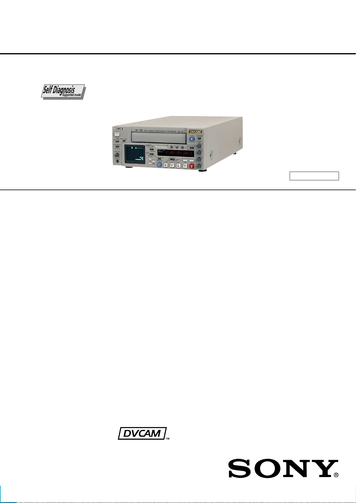
DSR-45/45P
RMT-DS5
SERVICE MANUAL
Ver 1.0 2002. 04
SPECIFICATIONS
System
Recording format DVCAM/DV (SP) format, rotating
2-head helical scan, digital
component recording
Video signal
DSR-45:
EIA STANDARD, NTSC color
system
DSR-45P:
CCIR STANDARD, PAL colour
system
Video
Quantization 8-bit
Sampling frequency
DSR-45:
13.5 MHz (4:1:1 Component)
DSR-45P:
13.5 MHz (4:2:0 Component)
Audio
Quantization 12-bit (non-linear) or 16-bit
(linear)
Sampling frequency
32 kHz (12-bit recording) or
48 kHz (16-bit recording)
Usable cassettes Standard-DVCAM cassettes and
Mini-DVCAM cassettes
Recording time Standard cassette
DVCAM:
184 minutes (PDV184)
180 minutes (DV270)
DV: 270 minutes (PDV184/
DV270)
Mini cassette
DVCAM: 40 minutes (PDVM40/
DVM60)
DV: 60 minutes (PDVM40/
DVM60)
(We recommend that you use
DVCAM cassettes.)
Clock
System Quartz locked, digital display
Power back-up Back-up duration: up to two weeks
(after an 8-hour charge)
Inputs
VIDEO IN REF.IN
BNC type
1 Vp-p (75 ohms, unbalanced)
S VIDEO IN Mini DIN 4-pin
Luminance signal: 1 Vp-p
(75 ohms, unbalanced)
Chrominance signal:
0.286 Vp-p (DSR-45)
0.3 Vp-p (DSR-45P)
(75 ohms unbalanced)
COMPONENT IN
Y: BNC type
1.0 Vp-p (75 ohms, unbalanced)
R-Y: BNC type
0.7 Vp-p (75 ohms, unbalanced)
(DSR-45: 75%, color bars / DSR45P: 100%, colour bars)
B-Y: BNC type
0.7 Vp-p (75 ohms, unbalanced)
(DSR-45: 75%, color bars / DSR-
45P: 100%, colour bars)
DV IN/OUT 4-pin jack (i.LINK)
AUDIO IN (CH-1 to CH-4)
Phono jack, –10/–2/+4 dBu,
Impedance more than 47 kohms,
unbalanced
Maximum input level:
DSR-45:
–10 : +18 dBu (about 6 Vrms)
–2 : +24 dBu (about 12.5 Vrms)
+4 : +30 dBu (about 25 Vrms)
DSR-45P:
–10 : +16 dBu (about 5 Vrms)
–2 : +22 dBu (about 10 Vrms)
+4 : +28 dBu (about 20 Vrms)
US Model
Canadian Model
DSR-45
AEP Model
UK Model
E Model
Austr alian Model
New Zealand Model
DSR-45P
R MECHANISM
TC IN BNC type
0.5 to 18 Vp-p (time code input)
0.5 to 4 Vp-p (through output)
Outputs
MONITOR VIDEO
Phono jack, 1 Vp-p (75 ohms,
unbalanced) (superimpose)
VIDEO OUT BNC type, 1 Vp-p (75 ohms,
unbalanced)
COMPONENT OUT
Y: BNC type
1.0 Vp-p (75 ohms, unbalanced)
R-Y: BNC type
0.7 Vp-p (75 ohms, unbalanced)
(DSR-45: 75%, color bars / DSR45P: 100%, colour bars)
B-Y: BNC type
0.7 Vp-p (75 ohms, unbalanced)
(DSR-45: 75%, color bars / DSR45P: 100%, colour bars)
S VIDEO OUT Mini DIN 4-pin
Luminance signal: 1.0 Vp-p
(75 ohms, unbalanced)
Chrominance signal:
0.286 Vp-p (DSR-45)
0.3 Vp-p (DSR-45P)
(75 ohms, unbalanced)
AUDIO OUT (CH-1 to CH-4)
XLR 3-pin, male, +4 dBu, 600
ohms loading, balanced
MONITOR AUDIO
Phono jack
TC OUT BNC type, 2.2 Vp-p, 600 ohms /
1.2 Vp-p, 75 ohms
0.5 to 4 Vp-p (through output,
600 ohms)
PHONES Stereo minijack, 8 Ω
– Continued on next page –
DIGITAL VIDEO CASSETTE RECORDER
DSR-45/45P
Remote control
RS-232C D-sub 9-pin (male)
RS-422A D-sub 9-pin (female)
CONTROL S IN Stereo minijack
LANC Stereo mini-minijack
LCD screen
Picture 5.1 cm (2 type)
Total dot number 123 200 (560 × 220)
General
Power requirements
100 to 240 V AC, 50/60 Hz
Power consumption
22 W (during playback)
Operating temperature
5 °C to 40 °C (41 °F to 104 °F)
Storage temperature
–20 °C to +60 °C
(–4 °F to +140 °F)
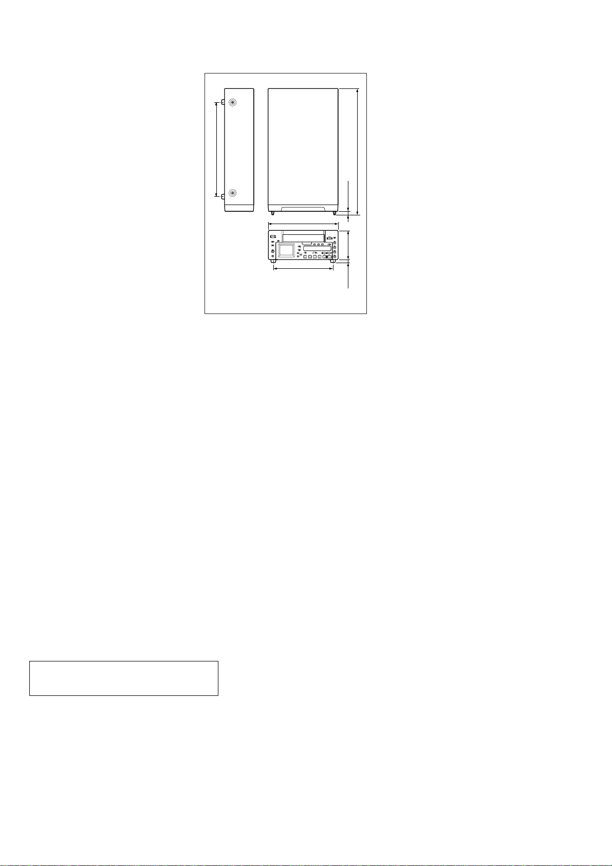
Dimensions Approx. 212 × 98 × 392.8 mm
3
/8 × 3 7/8 × 15 1/2 inches)
(8
(w/h/d, including projecting parts
and controls)
)
4
/
1
284 (11
212 (8 3/8)
175 (7)
Unit: mm (inches)
)
32
/
15
11.2 (
)10 (
2
/
1
88 (3
)
32
/
13
Mass Approx. 4.6 kg (10 lb. 2 oz.)
Supplied accessories
Remote Commander (1)
AC power cord (1)
Size AA batteries (2)
Cleaning cassette (1)
)
2
/
1
Operating instructions
Interface Manual for Programmers
(1)
Design and specifications are subject to change
392.8 (15
without notice.
Danger of explosion if battery is incorrectly replaced.
CAUTION
Replace only with the same or eqivalent type.
SAFETY-RELATED COMPONENT WARNING!!
COMPONENTS IDENTIFIED BY MARK 0 OR DOTTED
LINE WITH MARK 0 ON THE SCHEMATIC DIAGRAMS
AND IN THE PARTS LIST ARE CRITICAL TO SAFE
OPERATION. REPLACE THESE COMPONENTS WITH
SONY PARTS WHOSE PART NUMBERS APPEAR AS
SHOWN IN THIS MANU AL OR IN SUPPLEMENTS PUBLISHED BY SONY.
ATTENTION AU COMPOSANT AYANT RAPPORT
À LA SÉCURITÉ!
LES COMPOSANTS IDENTIFIÉS P AR UNE MARQUE 0
SUR LES DIAGRAMMES SCHÉMATIQUES ET LA LISTE
DES PIÈCES SONT CRITIQUES POUR LA SÉCURITÉ
DE FONCTIONNEMENT. NE REMPLACER CES COMPOSANTS QUE PAR DES PIÈCES SONY DONT LES
NUMÉROS SONT DONNÉS DANS CE MANUEL OU
DANS LES SUPPLÉMENTS PUBLIÉS PAR SONY.
– 2 –
SAFETY CHECK-OUT
(US Model only)
After correcting the original service problem, perform the following
safety checks before releasing the set to the customer:
DSR-45/45P
1. Check the area of your repair for unsoldered or poorly-soldered connections. Check the entire board surface for solder
splashes and bridges.
2. Check the interboard wiring to ensure that no wires are
“pinched” or contact high-wattage resistors.
3. Look for unauthorized replacement parts, particularly transistors, that were installed during a previous repair. Point them
out to the customer and recommend their replacement.
4. Look for parts which, though functioning, show obvious signs
of deterioration. Point them out to the customer and recommend their replacement.
5. Check the line cord for cracks and abrasion. Recommend the
replacement of any such line cord to the customer.
6. Check the B+ voltage to see it is at the values specified.
7. Check the antenna terminals, metal trim, “metallized” knobs,
screws, and all other exposed metal parts for AC leakage.
Check leakage as described below.
To Exposed Metal
Parts on Set
UNLEADED SOLDER
Boards requiring use of unleaded solder are printed with the leadfree mark (LF) indicating the solder contains no lead.
(Caution: Some printed circuit boards may not come printed with
the lead free mark due to their particular size)
: LEAD FREE MARK
Unleaded solder has the following characteristics.
• Unleaded solder melts at a temperature about 40 ˚C higher than
ordinary solder.
Ordinary soldering irons can be used but the iron tip has to be
applied to the solder joint for a slightly longer time.
Soldering irons using a temperature regulator should be set to
about 350 ˚C .
Caution: The printed pattern (copper foil) may peel away if the
heated tip is applied for too long, so be careful!
• Strong viscosity
Unleaded solder is more viscous (sticky , less prone to flow) than
ordinary solder so use caution not to let solder bridges occur
such as on IC pins, etc.
• Usable with ordinary solder
It is best to use only unleaded solder but unleaded solder may
also be added to ordinary solder.
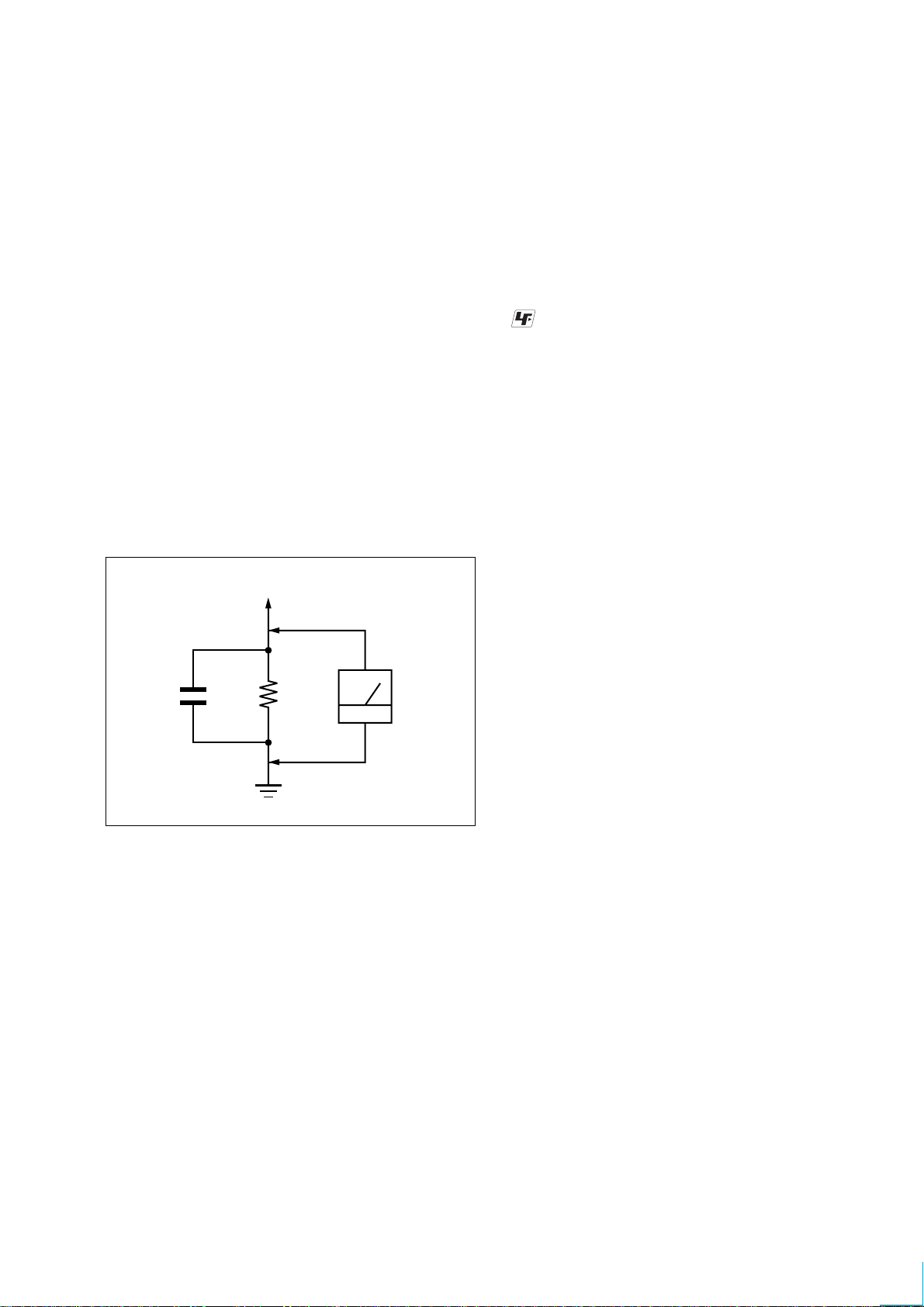
0.15 µF
1.5 k
Ω
Earth Ground
AC
Voltmeter
(0.75 V)
Fig. A Using AC voltmeter to check AC leakage
LEAKAGE TEST
The AC leakage from any exposed metal part to earth ground
and from all exposed metal parts to any exposed metal part having
a return to chassis, must not exceed 0.5 mA (500 microamperes).
Leakage current can be measured by any one of three methods.
1. A commercial leakage tester, such as the Simpson 229 or RCA
WT -540A. Follow the manuf acturers' instructions to use these
instruments.
2. A battery-operated A C milliammeter. The Data Precision 245
digital multimeter is suitable for this job.
3. Measuring the voltage drop across a resistor by means of a
VOM or battery-operated AC voltmeter. The “limit” indica-
tion is 0.75V, so analog meters must have an accurate low-
voltage scale. The Simpson 250 and Sanwa SH-63T rd are ex-
amples of a passive VOM that is suitable. Nearly all battery
operated digital multimeters that have a 2V A C range are suit-
able. (See Fig. A)
– 3 –

DSR-45/45P
TABLE OF CONTENTS
Section Title Page Section Title Page
SERVICE NOTE................................................................ 7
1. Note for Repair ............................................................ 7
SELF-DIAGNOSIS FUNCTION ..................................... 8
1. Self-diagnosis Function............................................... 8
2. Self-diagnosis Display................................................. 8
3. Service Mode Display ................................................. 8
4. Self-diagnosis Code Table .......................................... 9
1. GENERAL
Features ................................................................................ 1-1
Location and Function of Parts ............................................. 1-1
Displaying V arious Data ........................................................ 1-5
Notes on Video Cassettes..................................................... 1-6
Playback ................................................................................ 1-7
Recording .............................................................................. 1-9
Notes on Usage in the Editing System ................................. 1-10
Connections for Digital Non-linear Editing............................ 1-10
Connections for a Cut Editing System .................................. 1-11
Connections for an A/B Roll Editing System ........................ 1-11
Adjusting Edit Timing............................................................. 1-12
Setting the Time Code and User Bits .................................... 1-13
Synchronizing the Time Codes ............................................. 1-14
Adjusting the Sync and Subcarrier Phases
of the Video Signals............................................................... 1-15
Adjusting the Signals............................................................. 1-15
Duplication (Generating a Work Tape
with the Same Time Code).................................................... 1-16
Audio Dubbing ....................................................................... 1-17
Operating the Menus............................................................. 1-17
Troubleshooting ..................................................................... 1-22
Alarm Messages.................................................................... 1-23
Notes on Use......................................................................... 1-23
2. DISASSEMBLY
2-1. Upper Case, Bottom Plate .......................................... 2-1
2-2. Front Panel Block Assembly ....................................... 2-1
2-3. FR-183/DL-062 Boards ............................................... 2-2
2-4. LCD Module (LCD901)................................................ 2-2
2-5. Mechanism Deck ......................................................... 2-3
2-6. CM-59 Board ............................................................... 2-3
2-7. JC-21/DI-73 Boards .................................................... 2-4
2-8. VD-032 Board.............................................................. 2-4
2-9. Rear Panel Block Assembly........................................ 2-5
2-10. Circuit Boards Location-1 (Over All) ........................... 2-6
2-11. Circuit Boards Location-2 (Mechanism Deck) ............ 2-7
3. BLOCK DIAGRAMS
3-1. Overall Block Diagram 1.............................................. 3-1
3-2. Overall Block Diagram 2.............................................. 3-3
3-3. Overall Block Diagram 3.............................................. 3-5
3-4. Overall Block Diagram 4.............................................. 3-7
3-5. Overall Block Diagram 5.............................................. 3-9
3-6. Overall Block Diagram 6.............................................. 3-11
3-7. Overall Block Diagram 7.............................................. 3-13
3-8. Overall Block Diagram 8.............................................. 3-15
3-9. Overall Block Diagram 9.............................................. 3-17
3-10. Power Block Diagram 1............................................... 3-19
3-11. Power Block Diagram 2............................................... 3-21
3-12. Power Block Diagram 3............................................... 3-23
3-13. Power Block Diagram 4............................................... 3-25
3-14. Power Block Diagram 5............................................... 3-27
4. PRINTED WIRING BOARDS AND
SCHEMATIC DIAGRAMS ..................................... 4-1
4-1. Frame Schematic Diagram (1/2)................................. 4-3
Frame Schematic Diagram (2/2) ................................. 4-5
4-2. Schematic Diagrams ................................................... 4-7
• RP-234 (1/2)(REC/PB AMP 1)............................... 4-7
• RP-234 (2/2)(REC/PB AMP 2)............................... 4-9
• JC-21(1/14) (VIDEO PB AMP)............................... 4-11
• JC-21(2/14) (VIDEO A/D CONVERTER)............... 4-13
• JC-21(3/14) (CHROMA MIX) ................................. 4-15
• JC-21(4/14) (AFC).................................................. 4-17
• JC-21(5/14)
(VFD (VIDEO DSP, D/A CONVERTER)) ............... 4-19
• JC-21(6/14) (SFD).................................................. 4-21
• JC-21(7/14) (TFD).................................................. 4-23
• JC-21(8/14) (DV INTERFACE)............................... 4-25
• JC-21(9/14) (MECHANISM CONTROL 1)............. 4-27
• JC-21(10/14) (MECHANISM CONTROL 2)........... 4-29
• JC-21(11/14) (MODE CONTROL) ......................... 4-31
• JC-21(12/14) (AUDIO 1) ........................................ 4-33
• JC-21(13/14) (AUDIO 2) ........................................ 4-35
• JC-21(14/14) (POWER SUPPLY) .......................... 4-37
• DI-73 (1/9) (VIDEO D/A CONVERTER) ................ 4-39
• DI-73 (2/9) (VIDEO FIFO MEMORY)..................... 4-41
• DI-73 (3/9) (SYNC SHIFTER 1)............................. 4-43
• DI-73 (4/9) (SYNC SHIFTER 2)............................. 4-45
• DI-73 (5/9) (AUDIO HPF)....................................... 4-47
• DI-73 (6/9) (AUDIO A/D, D/A CONVERTER) ........ 4-49
• DI-73 (7/9) (AUDIO DSP)....................................... 4-51
• DI-73 (8/9) (AUDIO DSP CONTROL).................... 4-53
• DI-73 (9/9) (TIME CODE IN/OUT) ......................... 4-55
• VD-032 (1/16) (SYNC GENERATOR 1) ................ 4-57
• VD-032 (2/16) (SYNC GENERATOR 2) ................ 4-59
• VD-032 (3/16) (SYNC GENERATOR 3) ................ 4-61
• VD-032 (4/16) (VIDEO IN 1) .................................. 4-63
• VD-032 (5/16) (VIDEO IN 2) .................................. 4-65
• VD-032 (6/16) (VIDEO IN 3) .................................. 4-67
• VD-032 (7/16) (UVIC) ............................................ 4-69
• VD-032 (8/16) (VIDEO OUT 1) .............................. 4-71
• VD-032 (9/16) (VIDEO OUT 2) .............................. 4-73
• VD-032 (10/16) (VIDEO OUT 3) ........................... 4-75
• VD-032 (11/16) (AUDIO)........................................ 4-77
• VD-032 (12/16) (HI CONTROL)............................. 4-79
• VD-032 (13/16) (RS-232C/422 CONTROL) .......... 4-81
• VD-032 (14/16) (DC IN) ......................................... 4-83
• VD-032 (15/16) (DC/DC CONVERTER 1)............. 4-85
• VD-032 (16/16) (DC/DC CONVERTER 2)............. 4-87
• CM-59 (1/3) (DC/DC CONVERTER,
REEL MOTOR DRIVE) .......................................... 4-89
• CM-59 (2/3) (DRUM MOTOR DRIVE,
FL MOTOR DRIVE)................................................ 4-91
• CM-59 (3/3) (CAPSTAN MOTOR DRIVE,
CAM MOTOR DRIVE)............................................ 4-93
• MD-76 (TAPE SENSOR)........................................ 4-95
• CK-107 (EJECTION DETECT SWITCH)/
DL-062 (REMOTE CONTROL RECEIVER) .......... 4-97
• FC-087 (FRONT DOOR DETECT SWITCH)/
FM-037 (FRONT DOOR MOTOR) ......................... 4-98
• FR-183 (USER CONTROL) ................................... 4-99
• HP-135 (HEAD PHONE)........................................ 4-101
• PD-170 (1/2) (RGB DRIVER)................................. 4-103
• PD-170 (2/2) (TIMING GENERATOR)................... 4-105
• JK-216 (VIDEO/AUDIO IN/OUT) ........................... 4-107
• XL-005 (AUDIO OUT) ............................................ 4-109
• RS-082 (RS-422 DRIVER)/
RS-083 (RS-232C DRIVER) .................................. 4-111
•DV-032 (DV CONNECTOR)/
LS-060 (CONTROL JACK) .................................... 4-112
•ACS1581-MA (POWER) ........................................ 4-113
4-3. Printed Wiring Boards ................................................. 4-115
• RP-234 ................................................................... 4-115
• JC-21 ...................................................................... 4-119
• DI-73 ....................................................................... 4-123
– 4 –

DSR-45/45P
Section Title Page Section Title Page
• VD-032 ................................................................... 4-127
• CM-59 ..................................................................... 4-131
• MD-76 ..................................................................... 4-135
• CK-107/DL-062 ...................................................... 4-137
• FC-087/FM-037 ...................................................... 4-138
• FR-183.................................................................... 4-139
• HP-135 ................................................................... 4-143
• PD-170 ................................................................... 4-145
• JK-216 .................................................................... 4-147
• XL-005 .................................................................... 4-151
•RS-082/RS-083 ...................................................... 4-153
•DV-032 .................................................................... 4-155
• LS-060 .................................................................... 4-156
•ACS1581-MA.......................................................... 4-157
4-4. Waveforms................................................................... 4-161
4-5. Parts Location ............................................................. 4-179
5. ADJUSTMENTS
1. Before Starting Adjustment ......................................... 5-1
1-1. Adjusting Items when Replacing Main Parts
and Boards .................................................................. 5-2
1-2. Information (Mechanical Section) ............................... 5-4
5-1. MECHANICAL SECTION ADJUSTMENTS................ 5-5
5-1-1. Parts Replacement and Preparation
for Adjustment ........................................................ 5-5
1-1. Assembly/disassembly of Cassette Compartment ..... 5-5
1-2. How To Load/unload.................................................... 5-5
1-3. List of Service Tools .................................................... 5-6
1-4. About Mode Selector II ............................................... 5-7
5-1-2. Periodic Check ....................................................... 5-8
2-1. Cleaning of Rotary Drum Assembly ...................... 5-8
2-2. Cleaning of Tape Path System............................... 5-8
2-3. Periodic Checks ..................................................... 5-8
5-1-3. Parts Replacement................................................. 5-9
3-1. Tape Guide 1/8 and Guide Guard.......................... 5-9
3-2. Tape Guide 2/7 ....................................................... 5-9
3-3. Capstan Cover ....................................................... 5-10
3-4. Reel Motor .............................................................. 5-10
3-5. FL Motor Assembly, Gear A, Gear B and
Gear CD Assembly ................................................ 5-10
3-6. GL Arm S Assembly, GL Arm T Assembly,
Coaster S Assembly and Coaster T Assembly...... 5-11
3-7. MIC Base Guide, MIC Base Assembly and
MIC Base Spring .................................................... 5-12
3-8. Drum Cap, Drum Assembly and Tape Support ..... 5-12
3-9. Pinch Arm Assembly .............................................. 5-13
3-10. Capstan Motor........................................................ 5-13
3-11. Pendulum Retainer and
Pendulum Arm Assembly....................................... 5-13
3-12. Brake Arm S, Ratchet Brake T,
Tension Coil Spring (Brake), SBR Slider and FP-248
Flexible Board (Condensation Sensor).................. 5-14
3-13. Reel Table Assembly, Idler Gear A Assembly
and Idler Gear B..................................................... 5-14
3-14. Reel Base Retainer, Reel Base T Assembly and
Reel Base S Assembly (Reel Lock Release Block
and Reel Lock Release Spring) ............................. 5-15
3-15. Cam Motor, Motor Holder....................................... 5-15
3-16. TG2/7 Arm Block, TG2/7 Band Block and
Tension Coil Spring (TG2)/(TG7) ........................... 5-16
3-17. Sub-slider Arm, Sub-slider, Encoder Gear,
Main Cam Gear, Coupling Gear, Sub-cam Gear,
Pinch Slider and Loadeing Arm Assy .................... 5-17
3-18. Main Slider, Main Slider Arm and Pendulum
Stopper Assembly .................................................. 5-19
3-19. MD-76 Board and Encoder Retainer ..................... 5-20
3-20. Components of GL Arm S/T Assembly
(GL Arm Assembly, GL Helical Torsion Spring,
GL Gear)................................................................. 5-21
3-21. Components of MIC Base Assembly
(FP-104 Flexible Board, MIC Base)....................... 5-21
3-22. Components of Drum Assembly
(Motor FPC Assembly, Elastic Connector) ............ 5-22
3-23. Components of Pinch Arm Assembly (Tape Retainer,
Compression Coil Spring) ...................................... 5-22
3-24. Components of TG2/7 Arm Assembly (ET Magnet,
Magnet Holder) ...................................................... 5-22
5-1-4. Check and Adjustment ........................................... 5-23
4-1. Reel T able Height Check and Adjustment ............. 5-24
4-2. TG1/8 Height Check and Adjustment .................... 5-24
4-3. TG2/7 Height Check and Adjustment .................... 5-25
4-4. FWD/RVS Position Check and Adjustment ........... 5-25
4-5. Electric Tension Regulator Check and Adjustment
of TG2/7 Arm .......................................................... 5-26
4-6. FWD/RVS Back Tension Check and Adjustment... 5-27
4-7. Preparation for Adjustment and
Tape Path Check.................................................... 5-28
4-8. Track Adjustment and Check
(Checking the RF Waveform)................................. 5-29
4-9. Track Check............................................................ 5-29
4-10. CUE/REV Check .................................................... 5-30
4-11. Curl Check and Adjustment ................................... 5-30
4-12. Rising Check .......................................................... 5-31
5-2. SERVICE MODE ......................................................... 5-32
5-2-1. Adjusting Remote Commander .............................. 5-32
1. Used Adjustment Remote Commander................. 5-32
2. Precautions Upon Using the Adjusting Remote
Commander............................................................ 5-32
5-2-2. Data Processing ..................................................... 5-33
5-2-3. Ser vice Mode ......................................................... 5-34
1. Emergence Memory Address ................................ 5-34
2. EMG Code (Emergency Code).............................. 5-34
3. MSW Code ............................................................. 5-35
4. Bit V alue Discriminatiion ........................................ 5-36
5. Recorde of Use Check........................................... 5-37
6. LED Check ............................................................. 5-38
7. Switch Check (1).................................................... 5-39
8. Switch Check (2).................................................... 5-39
9. Switch Check (3).................................................... 5-39
10. Switch Check (4).................................................... 5-40
11. Switch Check (5).................................................... 5-40
5-3. VIDEO SECTION ADJUSTMENTS ............................ 5-41
3-1. Preparations Before Adjustment............................ 5-41
3-1-1. Equipment Used ..................................................... 5-41
3-1-2. Connection of Equipment....................................... 5-42
3-1-3. Checking the Input Signals .................................... 5-43
1. S VIDEO Input ........................................................ 5-43
2. VIDEO Input ........................................................... 5-43
3. COMPONENT Input............................................... 5-44
3-1-4. Adjustment Tapes................................................... 5-45
3-1-5. Input/output Level and Impedance ........................ 5-46
3-2. System Control System Adjustments .................... 5-47
1. Initializing the C, D, E Page Data........................... 5-47
2. Input of C Page Initial Data.................................... 5-47
3. Input of D Page Initial Data.................................... 5-47
4. Input of E Page Initial Data .................................... 5-47
5. Modification of C, D, E, Page Data ........................ 5-47
6. C Page Table .......................................................... 5-48
7. D Page Table .......................................................... 5-49
8. E Page Table .......................................................... 5-49
9. Node Unique ID No. Input ...................................... 5-51
3-3. Servo and RF System Adjustments....................... 5-53
1. Capstan FG Adjustment (CM-59 Board) ............... 5-53
2. PLL f0 Pre-adjustment (RP-234 Board) ................. 5-53
3. Switching Position Adjustment (RP-234 Board) .... 5-53
4. RF-AGC Adjustment (RP-234 Board).................... 5-53
5. CLK DELAY and AEQ Adjustment
(RP-234 Board) ...................................................... 5-54
6. PLL f0 Final Adjustment (RP-234 Board)............... 5-54
3-4. Video System Adjustments .................................... 5-54
3-4-1. JC-21 Board Adjustment ........................................ 5-54
1. VFD SPCK Adjustment (JC-21 Board).................. 5-54
– 5 –

DSR-45/45P
Section Title Page Section Title Page
2. A/D Converter Reference Voltage
Adjustment (1) (JC-21 Board)................................ 5-54
3. A/D Converter Reference Voltage
Adjustment (2) (JC-21 Board)................................ 5-54
4. Y Signal Clamp Reference Voltage Adjustment
(JC-21 Board)......................................................... 5-55
5. CR Signal Clamp Reference Voltage Adjustment
(JC-21 Board)......................................................... 5-55
6. CB Signal Clamp Reference Voltage Adjustment
(JC-21 Board)......................................................... 5-55
7. AFC Preliminary Adjustment (JC-21 Board) ......... 5-55
8. AFC Picture Frame Adjustment (JC-21 Board) ..... 5-55
9. AFC Adjustment (JC-21 Board)............................. 5-55
10. Pla yback Y Level Adjustment (JC-21 Board)......... 5-56
11. Playback C Level Adjustment (JC-21 Board) ........ 5-56
3-4-2. General Adjustment ............................................... 5-57
1. Playback Sync Level Adjustment
(VD-032 Board) ...................................................... 5-57
2. Playback Blanking Level Adjustment with 0%
Setup (VD-032 Board) ........................................... 5-57
3. Playback Signal Level Adjustment with 0% Setup
(VD-032 Board) ...................................................... 5-58
4. Playback CR Signal Level Adjustment with 0%
Setup (VD-032 Board) ........................................... 5-58
5. Playback CB Signal Level Adjustment with 0%
Setup (VD-032 Board) ........................................... 5-59
6. Playback CR Signal Delay Adjustment
(VD-032 Board) ...................................................... 5-59
7. Playback CB Signal Delay Adjustment
(VD-032 Board) ...................................................... 5-60
8. Encoder Free Run Adjustment (VD-032 Board) .... 5-60
9. Carrier Balance Adjustment (VD-032 Board) ........ 5-61
10. Burst Level Adjustment (VD-032 Board) ............... 5-61
11. Color Level Adjustment with 0% Setup
(VD-032 Board) ...................................................... 5-62
12. SC_V Phase Adjustment (VD-032 Board)............. 5-62
13. Playback Blanking Level Adjustment with 7.5%
Setup (VD-032 Board)(DSR-45) ............................ 5-63
14. Playback Y Signal Level Adjustment with 7.5%
Setup (VD-032 Board)(DSR-45) ............................ 5-63
15. Playback CR Signal Level Adjustment with 7.5%
Setup (VD-032 Board)(DSR-45) ............................ 5-64
16. Playback CB Signal Level Adjustment with 7.5%
Setup (VD-032 Board)(DSR-45) ............................ 5-64
17. Color Level Adjustment with 7.5% Setup
(VD-032 Board)(DSR-45)....................................... 5-65
18. Video Output Level Check (VD-032 Board)........... 5-65
19. S-Video Output Level Check (VD-032 Board) ....... 5-66
20. Monitor Terminal Output Level Adjustment
(JC-21 Board)......................................................... 5-67
21. E-E Blanking Level Adjustment (VD-032 Board)... 5-68
22. Component E-E Y Signal Level Adjustment
(VD-032 Board) ...................................................... 5-69
23. Component E-E CR Signal Level Adjustment
(VD-032 Board) ...................................................... 5-69
24. Component E-E CB Signal Level Adjustment
(VD-032 Board) ...................................................... 5-70
25. Component E-E CR Signal Delay Adjustment
(VD-032 Board) ...................................................... 5-71
26. Component E-E CB Signal Delay Adjustment
(VD-032 Board) ...................................................... 5-72
27. E-E Color Level Adjustment (VD-032 Board) ........ 5-73
28. Decoder Free Run Adjustment (VD-032 Board).... 5-74
29. Decoder HUE Adjustment (VD-032 Board).......... 5-75
30. S Video E-E Y Signal Level Adjustment
(VD-032 Board) ...................................................... 5-76
31. S Video E-E CR Signal Level Adjustment
(VD-032 Board) ...................................................... 5-76
32. S Video E-E CB Signal Level Adjustment
(VD-032 Board) ...................................................... 5-77
33. S Video E-E CR Signal Delay Adjustment
(VD-032 Board) ...................................................... 5-78
34. S Video E-E CB Signal Delay Adjustment
(VD-032 Board) ...................................................... 5-79
35. Composite E-E Y Signal Level Adjustment
(VD-032 Board) ...................................................... 5-80
36. Composite E-E CR Signal Level Check
(VD-032 Board) ...................................................... 5-80
37. Composite E-E CB Signal Level Check
(VD-032 Board) ...................................................... 5-81
38. H Phase Adjustment (VD-032 Board).................... 5-82
39. E-E SC Phase Adjustment (VD-032 Board).......... 5-82
40. Playback SC Phase Adjustment
(EXT SYNC OFF) (VD-032 Board) ........................ 5-83
41. Playback SC Phase Adjustment
(EXT SYNC ON) (VD-032 Board).......................... 5-83
3-5. LCD System Adjustments ...................................... 5-84
1. VCO Adjustment (PD-170 Board).......................... 5-84
2. D Range Adjustment (PD-170 Board) ................... 5-85
3. Bright Adjustment (PD-170 Board) ........................ 5-85
4. Contrast Adjustment (PD-170 Board).................... 5-86
5. Color Adjustment (PD-170 Board)......................... 5-86
6. V-COM Level Adjustment (PD-170 Board) ............ 5-87
7. V-COM Adjustment (PD-170 Board)...................... 5-87
8. White Balance Adjustment (PD-170 Board).......... 5-88
3-6. AUDIO System Adjustments.................................. 5-89
1. Audio PAL Data Input (DSR-45P) .......................... 5-90
2. Playing Level Check............................................... 5-91
3. E-E Level Check..................................................... 5-91
4. Frequency Characteristic Check............................ 5-92
5. Distortion Check..................................................... 5-93
6. HEAD PHONE Check ............................................ 5-94
7. E-E Maximum Input Check .................................... 5-94
8. E-E AUTO Check ................................................... 5-95
9. E-E Noise Level Check .......................................... 5-95
10. E-E AUTO Maximum Input Check ......................... 5-96
3-7. Time Code System Adjustments ........................... 5-97
1. Analog Through (E-E) Level Check ....................... 5-97
2. Time Code Reading Check.................................... 5-97
3. Internal Time Code Output Waveform Check........ 5-98
4. Internal Time Code Output Check ......................... 5-98
3-8. Arrangement Diagram for Adjustment Parts.......... 5-99
6. REPAIR PARTS LIST
6-1. EXPLODED VIEWS .................................................... 6-1
6-1-1. Overall Assembly ................................................... 6-1
6-1-2. Front Panel Assembly ............................................ 6-2
6-1-3. Rear Panel Assembly............................................. 6-3
6-1-4. Main Frame Assembly............................................ 6-4
6-1-5. CMX Block Assembly ............................................. 6-5
6-1-6. Mechanism Deck Assembly (Drum Assembly)...... 6-6
6-1-7. Mechanism Deck Assembly (Gear, Arm)............... 6-7
6-1-8. Mechanism Deck Assembly (Motor, MD Board).... 6-8
6-1-9. Mechanism Deck Assembly
(Cassette Compartment) ....................................... 6-9
6-2. ELECTRICAL PARTS LIST......................................... 6-10
Hardware List ........................................................................ 6-51
– 6 –
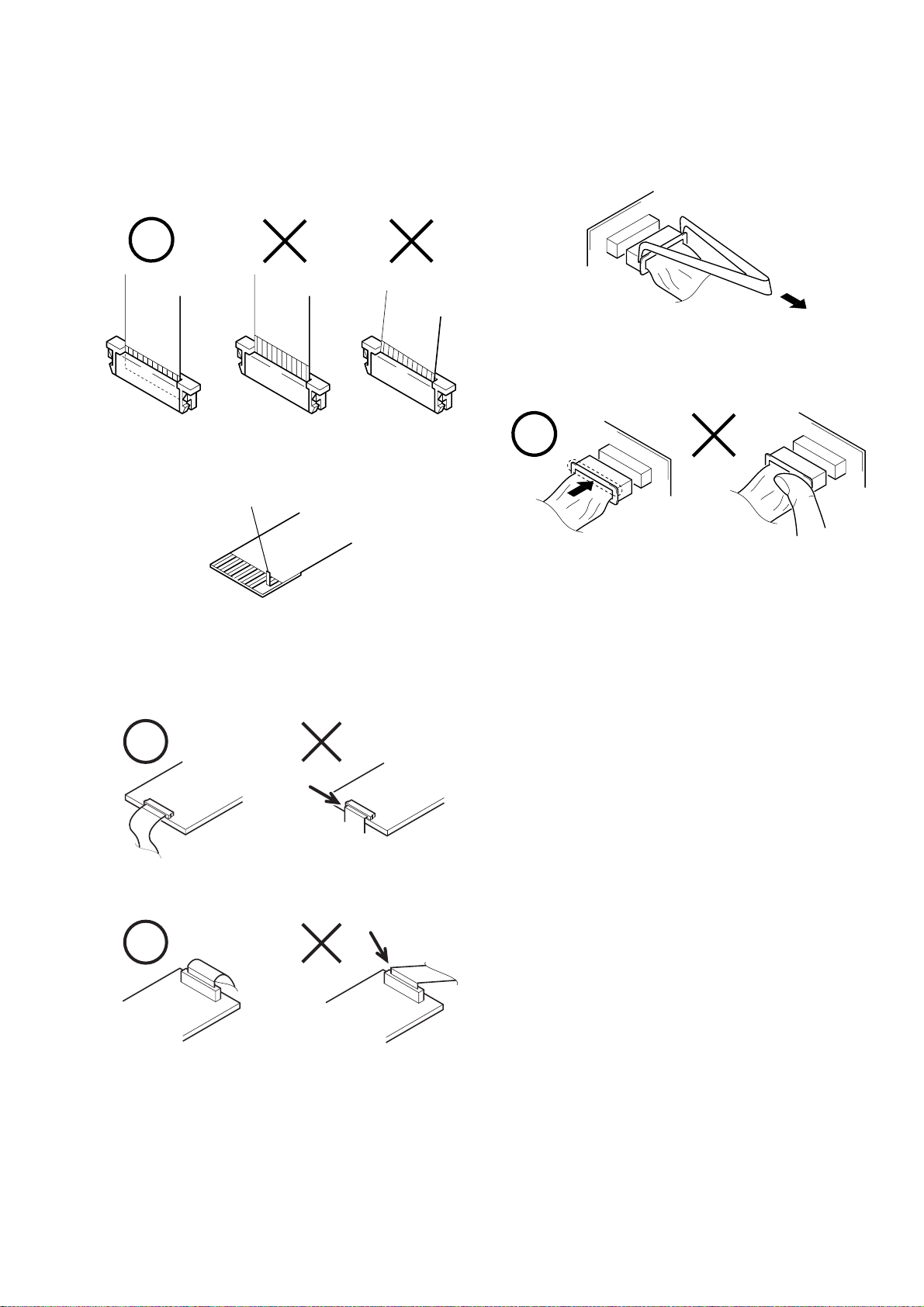
When installing a connector, don’t press down at wire of connector.
It is possible that a wire is snapped.
SERVICE NOTE
DSR-45/45P
1. NOTE FOR REPAIR
Make sure that the flat cable and flexible board are not cracked of
bent at the terminal.
Do not insert the cable insufficiently nor crookedly.
Cut and remove the part of gilt
which comes off at the point.
(Be careful or some pieces of
gilt may be left inside)
When remove a connector, don’t pull at wire of connector.
It is possible that a wire is snapped.
Do not fold down a flat cable at the edge of the inforcing board
which is the reverse side of pins when the flat cable is connected
to a connector.
If the flat cable is folded at that point, it may be a cause of
breaking of foil inside of the cable.
– 7 –
DSR-45/45P
SELF-DIAGNOSIS FUNCTION
1. Self-diagnosis Function
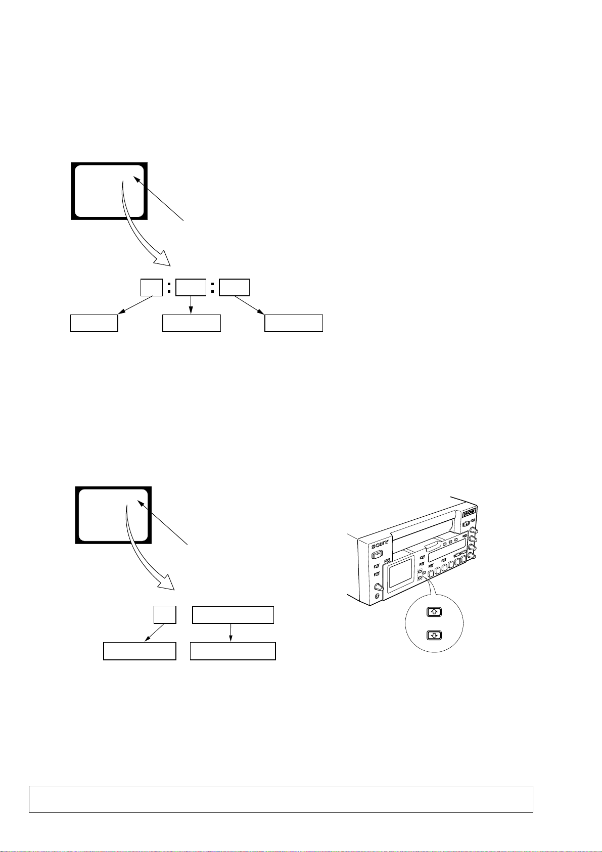
When problems occur while the unit is operating, the self-diagnosis function starts working, and displays on the LCD monitor what
to do. This function consists of two display; self-diagnosis display
and service mode display.
Details of the self-diagnosis functions are provided in the Instruction manual.
LCD monitor
C : 3 1 : 1 1
Blinks at 3.2Hz
1 1
Refer to page 10.
Self-diagnosis Code Table.
Repaired by:
C : Corrected by customer
H : Corrected by dealer
E : Corrected by service
engineer
3 1C
Block
Indicates the appropriate
step to be taken.
E.g.
31 ....Reload the tape.
32 ....Turn on power again.
2. Self-diagnosis Display
When problems occur while the unit is operating, the time code of
the LCD monitor shows a 4-digit display consisting of an alphabet and numbers, which blinks at 3.2 Hz. This 5-character display
indicates the “repaired by:”, “block” in which the problem occurred, and “detailed code” of the problem.
Detailed Code
3. Service Mode Display
The service mode display shows up to six self-diagnosis codes shown in the past.
3-1. Display Method
Set the “DISPLA Y SELECT” switc h to “DAT A”, turn on the power by the “PO WER” switch while pressing the “STOP” k ey, and continue
pressing the “STOP” key for 5 seconds continuously. The service mode will be displayed, and the time code will show the backup No. and
the 5-character self-diagnosis codes.
LCD monitor
[3] C : 3 1 : 1 1
Lights up
[3]
Backup No.
Order of previous errors
3-2. Switching of Backup No.
By pressing the “F” or “f” key, past self-diagnosis codes will be shown in order. The backup No. in the [] indicates the order in which the
problem occurred. (If the number of problems which occurred is less than 6, only the number of problems which occurred will be shown.)
[1] : Occurred first time [4] : Occurred fourth time
[2] : Occurred second time [5] : Occurred fifth time
[3] : Occurred third time [6] : Occurred the last time
C : 3 1 : 1 1
Self-diagnosis Codes
3-3. End of Display
Turning OFF the power supply will end the service mode display.
Note: The “self-diagnosis displa y” data will be backed up by the coin-type lithium battery (VD-032 board BT701). When this
coin-type lithium battery is disconnected, the “self-diagnosis display” data will be lost by initialization.
– 8 –
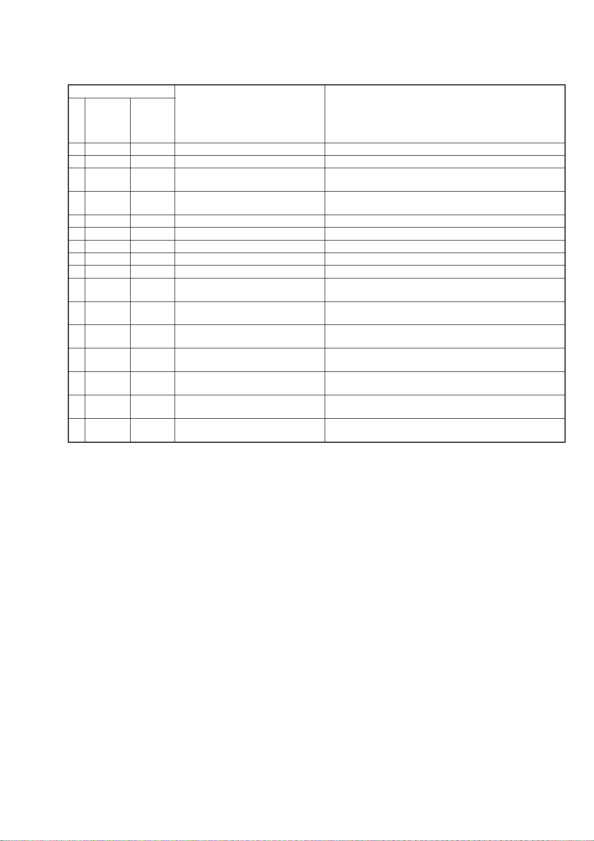
4. Self-diagnosis Code Table
Self-diagnosis Code
DSR-45/45P
Repaired by:
C
C
C
C
C
C
C
C
C
C
C
C
C
C
C
C
Block
Function
21
22
31
31
31
31
31
31
31
32
32
32
32
32
32
32
Detailed
Code
00
00
10
11
22
23
30
40
42
10
11
22
23
30
40
42
Symptom/State
Condensation.
Video head is dirty.
LOAD direction. Loading does not
complete within specified time
UNLOAD direction. Loading does not
complete within specified time
T reel fault.
S reel fault.
FG fault when starting capstan.
FG fault when starting drum.
FG fault during normal drum operations.
LOAD direction loading motor time-
out.
UNLOAD direction loading motor
time-out.
T reel fault.
S reel fault.
FG fault when starting capstan.
FG fault when starting drum.
FG fault during normal drum
operations.
Correction
Remove the cassette, and insert it again after one hour.
Clean with the optional cleaning cassette.
Load the tape again, and perform operations from the beginning.
Load the tape again, and perform operations from the beginning.
Load the tape again, and perform operations from the beginning.
Load the tape again, and perform operations from the beginning.
Load the tape again, and perform operations from the beginning.
Load the tape again, and perform operations from the beginning.
Load the tape again, and perform operations from the beginning.
Disconnect the AC power cord.
After reconnecting it, operate the unit.
Disconnect the AC power cord.
After reconnecting it, operate the unit.
Disconnect the AC power cord.
After reconnecting it, operate the unit.
Disconnect the AC power cord.
After reconnecting it, operate the unit.
Disconnect the AC power cord.
After reconnecting it, operate the unit.
Disconnect the AC power cord.
After reconnecting it, operate the unit.
Disconnect the AC power cord.
After reconnecting it, operate the unit.
– 9 –
Overview
Features
The DSR-45/45P is a digital videocassette recorder
1
/4-inch tape. Offering the DVCAM™ digital
using
recording format, the DSR-45/45P produces stable,
superior picture quality by digitally processing and
separating image signals into color difference signals
and a luminance signal (component video). Equipped
with five kinds of remote control connector (RS-422A/
RS-232C/LANC/CONTROL S/i.LINK), the DSR-45/
45P allows you to configure various connection. The
built-in color LCD monitor lets you check images
easily.
The main features of the DSR-45/45P are described
below.
DVCAM Format
DVCAM is based on the consumer DV format,
which uses the 4:1:1 component digital format
(DSR-45) or the 4:2:0 format (DSR-45P), and
1
/4-inch digital recording format for
provides a
professional use.
For details, see “Compatibility of DVCAM and DV Format”
on page 101 (GB).
SECTION 1
Chapter
1
High picture quality, high stability
Video signals are separated into color difference
signals and a luminance signal, which are encoded and
compressed to one-fifth size before being recorded to
ensure stable and superb picture quality.
Because the recording is digital, multi-generation
digital dubbing can be performed with virtually no
deterioration of quality.
Wide track pitch
The recording track pitch is about 15 µm, fully 50
percent wider than the DV format’s 10 µm track pitch.
Thanks to this feature, the DVCAM format fully meets
the reliability and precision requirements of
professional editing.
High-quality PCM digital audio
PCM recording makes for a wide dynamic range and a
high signal-to-noise ratio, thereby enhancing sound
quality.
There are two recording modes: 2-channel mode (48
kHz sampling and 16 bit linear code), which offers
sound quality equivalent to the DAT (Digital Audio
Tape) format, or 4-channel mode (32 kHz sampling
and 12 bit nonlinear code), which provides four
channel simultaneous recording/playback.
Chapter 1 Overview9 (GB)
GENERAL
Chapter 1 Overview
Chapter 1 Overview
.........................................................................................................................................................................................................
This section is extracted from DSR45/45P instruction manual.
Features
DV format compatibility
The unit can perform recording and playback in the
DV-format (SP mode only). (Recording/playing an
image in LP mode is not available.)
Choice of two cassette sizes
The unit can use both standard-size and mini-size
DVCAM/DV cassettes.
•According to cassette size, the position of the reel
drive plates automatically changes.
•The maximum recording/playback times are 184
minutes for standard size cassettes and 40 minutes for
mini-size cassettes (DVCAM format).
Remote control
The unit can be operated by remote control from the
CONTROL S system Remote Control Unit (DSRM20, not supplied), or an editing controller that has an
RS-422A, RS-232C, or LANC jack.
High-speed search function
If you use an editing controller or the Remote Control
Unit (DSRM-20, not supplied), the unit has a picture
search function that allows you to view color pictures
at playback speeds up to 14 times normal speed (DSR-
45) or up to 17 times normal speed (DSR-45P) in both
forward and reverse directions.
You can also search frame-by-frame in jog mode.
While searching for scenes, you can also hear playback
audio.
Internal time code generator/reader
The unit contains a time code generator/reader that can
generate and read longitudinal time code (LTC) in the
SMPTE format (DSR-45) or EBU format (DSR-45P).
This unit can output the time code read from tape as an
analog (LTC) signal, and receive externally generated
time code (LTC).
1) i.LINK and the i.LINK logo “
indicate that this product is in agreement with IEEE
1394-1995 specifications and their revisions.
10
(GB) Chapter 1 Overview
”are trademarks and
DSR-45/45P
Digital slow playback
The unit has a frame memory function that allows slow
playback without noise. This is available only at +
time speed and –
1
/3-time speed.
TBC (Time Base Corrector)
The unit has a digital TBC that provides jitter-free
video output for analog signals. The video output
level, chrominance signal output level, and setup level
(DSR-45 only) can all be adjusted.
Jog audio function
If you use the Remote Control Unit (DSRM-20, not
supplied) or an editing controller, audio can be
monitored at various playback speeds when in jog
mode.
Various interfaces
The unit provides many types of interface connectors.
• Analog video: component video, composite video, Svideo (IN/OUT)
• Analog audio: XLR (3-pin) output connectors
provide four channel simultaneous playback, phono
jack type input connectors.
1)
• i.LINK (DV)
• TC (Time code): BNC type input/output connectors
: i.LINK-compliant DV jack (4-pin)
allows input or output of digital video/audio signals
in DVCAM/DV format.
allow input/output of the time code between this unit
and an external device.
1
/3-
Other Features
Built-in color LCD monitor
The unit has a 2-type color LCD (liquid crystal
display) monitor that lets you verify images on the
spot. You can see the setup menus, audio levels, and
system statuses. Menus and data can be superimposed
over the picture being displayed.
Duplicate, including cassette memory data
Using an i.LINK cable, you can duplicate a tape that
includes time code and cassette memory data, etc. If
the original tape has blank portions, you can duplicate
the tape skipping those portions.
Audio dubbing function
The unit allows you to record just the sound onto the
recorded tape (audio dubbing). (The tape must be
recorded in DVCAM format and the audio mode must
be 32 kHz.)
Menu system for functionality and
operation settings
The unit provides a menu system to make its various
functions easier to use and set up.
Superimposition function
Time code, warnings, menus, and other text data can
be superimposed on the MONITOR VIDEO output
and the LCD monitor.
Easy maintenance functions
• Self-diagnostics/alarm functions: The system
automatically detects an invalid operation, an invalid
connection or a malfunction, and displays a
description, a cause and a recovery method on the
LCD monitor and outputs the data from the
MONITOR VIDEO connector.
• Digital hours meter: A digital hours meter counts
four types of time data—operating time, drum
rotation time, tape running time, and tape threading/
unthreading. The digital hours data are indicated on
the menu.
......................................................................................
, , and are trademarks of Sony
Corporation.
Chapter 1 Overview11 (GB)
Chapter 1 Overview
Location and Function of Parts
Location and Function of Parts
Front Panel
1 Cassette compartment
Chapter 1 Overview
2 REMOTE/LOCAL switch
3 ON/STANDBY
switch and
lamp
4 TIMER selector
5 AUDIO MONITOR
selector
6 PHONE LEVEL
control knob
7 PHONES jack
8 RESET button
1 Monitor display section
(see page 14 (GB))
9 CHARACTER DISPLAY
(MONITOR OUT) switch
1 Cassette compartment
Insert a standard-size or mini-size DVCAM cassette.
To open or close the compartment, press the EJECT
button qa.
For details of cassettes that can be used, see “Notes on
Video Cassettes” on page 30 (GB).
2 REMOTE/LOCAL switch
Set this switch to REMOTE when controlling the unit
from an external device connected to the RS-422A/RS232C connector on the rear panel.
REMOTE: Enables an external device connected to
the RS-422A/RS-232C connector.
When setting this switch to REMOTE, you can
restrict the tape transport and menu control
buttons on the front panel, the Remote
Commander, and the optional Remote Control
Unit connected to the CONTROL S IN jack using
LOCAL ENBL on the REMOTE menu.
For details on the REMOTE menu, see “REMOTE
menu” on page 80 (GB).
LOCAL: Disables an external device connected to
the RS-422A/RS-232C connector.
12
(GB) Chapter 1 Overview
CH1/2
MIN MAX
1
CH3/4
4 Display window
(see page 19 (GB))
qa EJECT button
CH-1
CH-2
3 Audio control section
(see page 18 (GB))
CH-3
CH-4
2 Tape transport control
section
(see page 16 (GB))
0 INPUT SELECT
selector
The switch setting enables/disables external devices as
follows.
RS-422A
RS-232C
a)
LANC
CONTROL S IN
Remote Commander
DV (i.LINK) Enabled Enabled
a) You also need to set the remote selector on the rear panel
according to the connector to which you connect a
device.
b) Depending on the setting of COMMANDER on the
OTHERS menu.
Notes
•An external device connected to the LANC jack can
operate the unit regardless the setting of this switch as
long as the remote selector is set to LANC.
a)
a)
b)
b)
REMOTE LOCAL
Enabled Disabled
Enabled Disabled
Enabled Enabled
Depending on the Enabled
setting of LOCAL
ENBL on the
REMOTE menu
Depending on the Enabled
setting of LOCAL
ENBL on the
REMOTE menu
1-1
DSR-45/45P
Location and Function of Parts
•In addition to the Remote Commander supplied with
the unit, the unit accepts signals from any Sony
Remote Commander whose command mode is set to
VTR4. When this switch is set to REMOTE, the
Remote Commander functions depending on the
setting of LOCAL ENBL on the REMOTE menu. If
you want to disable the control from any Remote
Commander, set COMMANDER on the OTHERS
menu to CONTROL S.
•The TIMER selector 4 setting has a higher priority
than this switch setting.
•When this switch is set to REMOTE, the ON/
STANDBY switch 3 does not work. To enable the
ON/STANDBY switch, set this switch to LOCAL or
set LOCAL ENBL on the REMOTE menu to ALL
KEYS.
3 ON/STANDBY switch and lamp
Press this switch to turn the unit on. The ON/
STANDBY lamp lights up in green. When you press
this switch again, the unit goes into the standby mode
and the lamp lights up in red.
Note
When the REMOTE/LOCAL switch is set to
REMOTE, this switch does not work. To enable this
switch, set the REMOTE/LOCAL switch to LOCAL
or set LOCAL ENBL on the REMOTE menu to ALL
KEYS.
4 TIMER selector
Use to select Auto Repeat or recording using an
external AC timer (not supplied).
REPEAT: Whenever the power is connected to this
unit, a tape rewinds to its beginning automatically
and playback starts. The unit repeats the playback
from the beginning to the first index (if there is no
index on the tape, to an unrecorded portion; if
there is no unrecorded portion, to the tape end).
Auto Repeat also functions if you set this selector
to REPEAT during playback or rewinding.
For details on Auto Repeat, see “Automatically playing
back a tape repeatedly (Auto Repeat)” on page 39 (GB).
OFF: Auto Repeat or timer recording is released.
REC: Recording begins the moment the power is
connected to the unit.
Note
This selector setting has a higher priority than the
REMOTE/LOCAL switch 2 setting.
5 AUDIO MONITOR selector
Use to select the audio track you want to listen to
through the PHONES jack 7 or MONITOR AUDIO
jack.
CH-1/2: channels 1/2 only
MIX: channels 1/2 and channels 3/4
CH-3/4: channels 3/4 only
6 PHONE LEVEL control knob
Controls the volume of the headphones connected to
the PHONES jack 7.
7 PHONES jack
Connect stereo headphones for monitoring sounds
during recording or playback. The audio signal you
want to monitor can be selected with the AUDIO
MONITOR selector 5.
8 RESET button
Press this button to initialize the time set on the
internal clock and the time code of the FREE RUN
setting. Use the tip of a ball-point pen or similar tool to
press this button. (The menu item settings are
maintained.)
9 CHARACTER DISPLAY (MONITOR OUT)
(data items superimposed on an external monitor)
switch
Set this switch to ON to superimpose data items on the
MONITOR VIDEO output. Even if you set it to OFF,
the tape label, title and data codes (camera data and
date/time recorded by a camera) are superimposed.
Note
To choose whether or not the tape label, title, or data
codes are displayed, use the menu items. Also, you can
select the data code items to be displayed by pressing
the DATA CODE button on the Remote Commander.
0 INPUT SELECT selector
You can select DV, S VIDEO, VIDEO, or
COMPONENT to input signals.
The type of signal selected is displayed on the Data
screen on the LCD monitor on the front panel.
Notes
•When you input signals to the DV jack, the following
settings are disabled:
– Setting of the audio input level control selector
(–10/–2/+4)
– Audio recording level
(Continued)
Chapter 1 Overview13 (GB)
Chapter 1 Overview
– Audio recording level adjustment mode (AUTO/
MANU)
– Audio mode (32 kHz/48 kHz)
– Audio limiter
– Color bars (Cannot be displayed)
Chapter 1 Overview
•If you change this selector, the screen may
momentarily become bright or noise may appear.
This noise will be recorded.
• Do not change this selector setting during recording.
Otherwise, the recorded image will be distorted or the
signal output from the DV jack will be interrupted.
Also, the unit may mistakenly recognize that a
copyright protected signal has been input.
qa EJECT (OPEN/CLOSE) (open/close the cassette
compartment) button
Press this button to open or close the cassette
compartment. If you press this button while a cassette
is inside the unit, the compartment opens and the
cassette is ejected.
After removing the cassette, press this button again to
close the compartment.
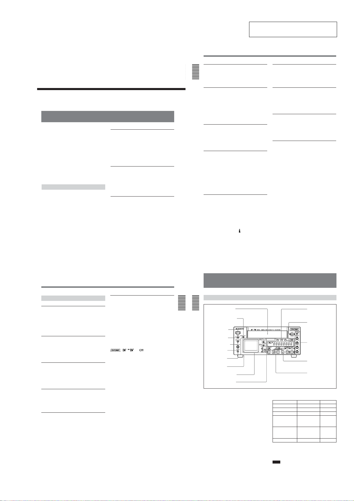
1 Monitor display section
2 CHARACTER DISPLAY
(LCD) selector
1 LCD monitor
1 LCD (Liquid Crystal Display) monitor
Displays the playback or EE
superimposed time data, status information, menu,
audio levels meters, etc. are displayed.
Notes
•The data items superimposed on the LCD monitor are
the same as items superimposed on a monitor
connected to the MONITOR VIDEO jack.
You cannot make two monitors display different data
items individually.
•The backlight used in the built-in LCD monitor
deteriorates with prolonged use. If the brightness of
the LCD monitor cannot be adjusted, consult your
Sony dealer.
.........................................................................................................................................................................................................
1) “EE” stands for “Electric to Electric.” In EE mode, the
video and audio signals that are input to the VCR’s
recording circuitry do not pass through any magnetic
conversion circuits but instead are output via electric
14
(GB) Chapter 1 Overview
1)
pictures. Also,
For details on the maintenance of the LCD monitor, see
page 99 (GB).
2 CHARACTER DISPLAY (LCD) (data items
superimposed on the LCD monitor) selector
Use to superimpose data items on the LCD monitor.
OFF: No data items are superimposed except the
tape label, title, data codes (camera data, and date/
time recorded by a camera).
ON: Data items are superimposed.
ON (BLACK BACK): Data items are displayed on a
black background.
circuits only. This mode is used to check the input
signals and adjust input levels. The pictures output in EE
mode are referred to as EE pictures.
3 DISPLAY SELECT selector
4 EXEC or FINE (AUDIO)
button
5 J / j buttons
Notes
•To choose whether or not the tape label, title, or data
codes are displayed, use the menu items. Also, you
can select the data code items to be displayed by
pressing the DATA CODE button on the Remote
Commander.
• To adjust the menu items, set the LCD monitor or a
monitor connected to the MONITOR VIDEO jack to
display the menu. When neither of the monitors is set,
you cannot adjust the menu items.
3 DISPLAY SELECT selector
Selects the data items displayed on the LCD monitor
or a monitor connected to the MONITOR VIDEO
jack.
MENU: displays the menu.
DATA: displays time code, remaining tape time, type
of input signal selected, audio mode, presence or
absence of cassette memory, tape label, title, etc.
AUDIO: displays audio levels.
Notes
•You can use the Remote Control Unit (DSRM-20, not
supplied) or the supplied Remote Commander to
search for a scene using search signals on the tape. In
this case, you can search for the scene regardless of
this selector setting.
To display the “–/+” which indicates the direction to
search, set this selector to DATA.
•If you change the selector setting during a search with
the cassette memory, the search aborts.
4 EXEC (execute) or FINE (AUDIO) (fine audio
levels) button
When the DISPLAY SELECT selector 3 is set to
MENU, the button functions as the EXEC (execute)
button. Press this button to change the setting on the
menu items.
For details on the menu, see “Operating the Menus” on
page 76 (GB).
When the DISPLAY SELECT selector 3 is set to
AUDIO, the button functions as the FINE (fine audio
levels) button. While you are holding this button
down, the enlarged audio levels meters are displayed.
You can confirm or adjust audio levels precisely on
these enlarged audio levels meters. To select an
enlarged portion, use REF LEVEL on the AUDIO SET
menu.
For details on fine audio levels screen, see “Fine audio
levels screen” on page 29 (GB).
For details on the AUDIO SET menu, see “AUDIO SET
menu” on page 88 (GB).
5 J / j buttons
When the DISPLAY SELECT selector 3 is set to
MENU, you can select a menu item by pressing these
buttons.
For details on the menu, see “Operating the Menus” on
page 76 (GB).
When the DISPLAY SELECT selector 3 is set to
DATA, you can adjust the brightness of the LCD
monitor by pressing these buttons. During the
adjustment, the brightness level is displayed as
illustrated below. It disappears one second after you
have adjusted the brightness.
BRT
Chapter 1 Overview15 (GB)
Chapter 1 Overview
Location and Function of Parts
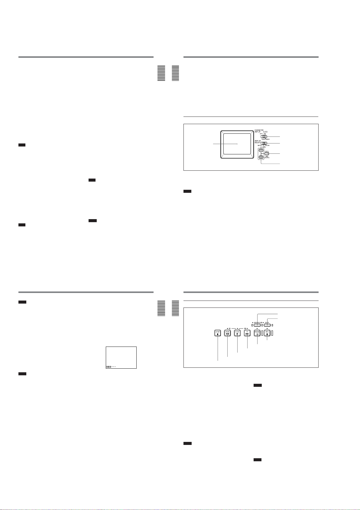
2 Tape transport control section
Chapter 1 Overview
2 REW button/indicator
1 STOP button
1 STOP button
Press this button to stop the current tape transport
operation.
2 REW (rewind) button/indicator
When you press this button, the indicator lights and the
tape starts rewinding. During rewind, the picture does
not appear on the monitor (you can see the picture as it
is seen in the EE mode).
To locate a scene while monitoring the picture, hold
this button down during rewind, playback or in the
playback pause mode.
If you press the PLAY button while holding this button
down during stop, the tape is rewound to its beginning
and starts playback automatically (during rewind, the
REW indicator lights and the PLAY indicator flashes).
You can change the tape transport mode in FF/REW
SPD on the VTR SET menu.
For details on the VTR SET menu, see “VTR SET menu” on
page 90 (GB).
Notes
•If you set EE/PB SEL on the DISPLAY SET menu to
PB, the EE pictures or EE sounds are not output
while the tape rewinds.
•If you set FF/REW SPD on the VTR SET menu to
SHUTTLEMAX, you can display the picture while
the tape rewinds.
For details on the tape transport speed of the
SHUTTLEMAX setting, see “FF/REW SPD” in the “VTR
SET menu” on page 90 (GB).
16
(GB) Chapter 1 Overview
7 AUDIO DUB button/indicator
8 DUP button/indicator
6 REC button/indicator
5 PAUSE button/indicator
4 FF button/indicator
3 PLAY button/indicator
3 PLAY button/indicator
When you press this button, the indicator lights and
playback begins.
Notes
•If the unit is playing a part of the tape where the
format has been changed between the DVCAM
format and the DV format or where the color system
of the recorded signals has been changed between
PAL and NTSC, the picture and sound are distorted.
•The unit can play back only tapes recorded in the
DVCAM format or in the SP mode of the DV format.
4 FF (fast forward) button/indicator
When you press this button, the indicator lights and the
tape is fast forwarded. During fast forward, the picture
does not appear on the monitor (you can see the
picture as it is seen in the EE mode).
To locate a scene while monitoring the picture, hold
this button down during fast forward, playback or in
the playback pause mode.
You can change the tape transport mode in FF/REW
SPD on the VTR SET menu.
For details on the VTR SET menu, see “VTR SET menu” on
page 90 (GB).
Notes
•If you set EE/PB SEL on the DISPLAY SET menu to
PB, the EE pictures or EE sounds are not output
while the tape is fast-forwarded.
1-2
Location and Function of Parts
DSR-45/45P
•If you set FF/REW SPD on the VTR SET menu to
SHUTTLEMAX, you can display the picture while
fast-forwarding the tape.
For details on the tape transport speed of the
SHUTTLEMAX setting, see “FF/REW SPD” in the “VTR
SET menu” on page 90 (GB).
5 PAUSE button/indicator
When you press this button during recording, playing,
or audio dubbing, the current operation goes into the
pause mode. Pressing this button again resumes the
operation. The indicator lights while the unit is in the
pause mode.
6 REC (record) button/indicator
When you press the PLAY button while holding this
button down, the PLAY and REC indicators light and
recording starts.
When the unit is in the stop mode, you can check EE
signals for an image, sound and time code by pressing
this button. During this check, the REC indicator
lights. To stop this operation, press the STOP button.
For details, see “EE/PB SEL” in the “DISPLAY SET menu”
on page 85 (GB). For details on time codes, see “DSR-45/
45P time codes” on page 63 (GB).
Note
The unit can record only in the DVCAM format or in
the SP mode of the DV format.
7 AUDIO DUB (audio dubbing) button/indicator
Use this button to dub sounds. The indicator lights
while sounds are being dubbed.
For details on audio dubbing, see “Audio Dubbing” on
page 74 (GB).
When the unit is in the stop mode and the INPUT
SELECT selector is set to other than DV, you can
listen to the EE sound by pressing this button. During
this operation, the indicator lights. To stop the
operation, press the STOP button.
For details, see “EE/PB SEL” in the “DISPLAY SET menu”
on page 85 (GB).
8 DUP (duplicate) button/indicator
Use to duplicate a tape, including the time code.
During duplication, the indicator lights.
For details on the duplicate function, see “Duplication
(generating a work tape with the same time code)” on page
69 (GB).
When the unit is in the stop mode and a DV signal is
selected and input, you can check the EE signals for an
image, sound and time code by pressing this button.
During the check, the indicator lights. To stop this
operation, press the STOP button.
For details, see “EE/PB SEL” in the “DISPLAY SET menu”
on page 85 (GB). For details on time codes, see “DSR-45/
45P time codes” on page 63 (GB).
Chapter 1 Overview
3 Audio control section
Chapter 1 Overview
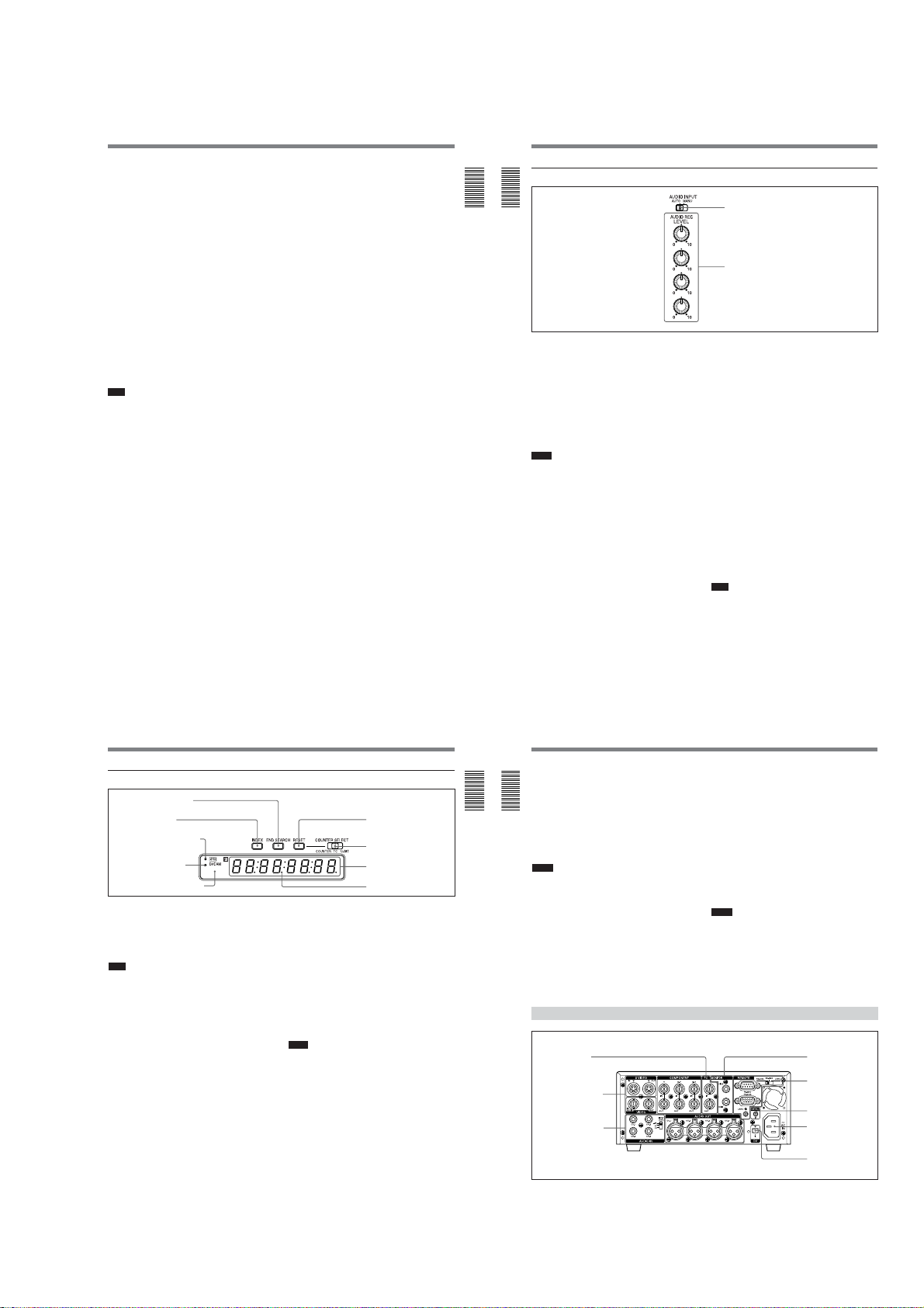
1 AUDIO INPUT (AUTO/MANU) switch
Switches the audio recording level adjustment mode.
AUTO: Adjusts the recording level automatically.
The AUDIO REC LEVEL control knobs (CH-1 to
CH-4) 2 are disabled.
To link the AGC (Auto Gain Control) of the audio
channels (CH-1/2 or CH-3/4), set AGC CH1,2
(AGC CH3,4) on the AUDIO SET menu to
LINKED.
MANU: Enables the AUDIO REC LEVEL control
knobs (CH-1 to CH-4) 2 to manually adjust the
recording level.
Notes
• When DV signals are input to the unit, the sound
recorded retains the signal level input, regardless of
the setting of this switch.
• If the sound is louder than the input amplifier’s
dynamic range, the AUTO setting is ineffective.
• Even if you set this switch to AUTO, unless the
setting of the INPUT LEVEL selector on the rear
panel is appropriate, there may be clipping and noise.
• The audio level is automatically adjusted to an
appropriate level when you select AUTO. It takes
about 20 seconds for the audio level to be stabilized
in the following cases.
– immediately after powering on
– immediately after stopping a playback operation
– immediately after switching the audio mode in
AUDIO MODE on the AUDIO SET menu
1 AUDIO INPUT switch
CH-1
CH-2
2 AUDIO REC LEVEL control knobs
CH-3
CH-4
• If LIMITER on the AUDIO SET menu has been set
to ON while you are manually adjusting the audio
level, you can record the sound without clipping even
if the audio input level is high as long as the level is
within the amplifier’s dynamic range. The LIMITER
setting is available only when this switch is set to
MANU.
2 AUDIO REC LEVEL control knobs (CH-1 to
CH-4)
By turning these knobs, you can adjust the analog
audio input signal levels for CH-1 to CH-4
respectively. You can adjust the audio signal level only
if the AUDIO INPUT (AUTO/MANU) switch 1 has
been set to MANU.
To display the audio levels meters on the LCD
monitor, set the DISPLAY SELECT selector on the
monitor display section to AUDIO (audio screen).
While you are holding down the FINE (fine audio
levels) button when the audio levels meters are
displayed, a part of the audio levels meters will be
enlarged (Fine audio levels screen). To select the
enlarged portion, use REF LEVEL on the AUDIO SET
menu. You can adjust the audio levels precisely on this
screen.
For details on the audio screen, see “Audio screen” on page
28 (GB).
Note
You cannot adjust the audio level of the DV signal.
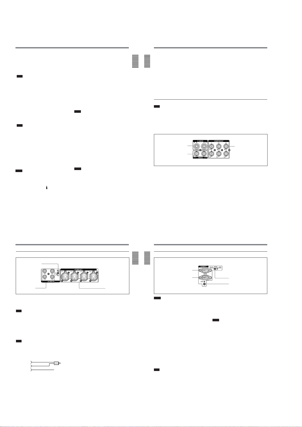
4 Display window
1 END SEARCH button
2 INDEX button
3 q (cassette) indicator
4 DVCAM indicator
5 Remote control detector
1 END SEARCH button
When you press this button, the unit searches the tape
and plays back the last five-second recorded picture.
After playback, the unit turns to the stop mode. Use
this function to record another image at the end of the
last recorded portion or to check the image itself.
Note
If you use a cassette without cassette memory, the end
search function does not work once you eject the
cassette after you have recorded on the tape. If you use
a cassette with cassette memory, the end search
function works even if you have ejected the cassette
one or more times. If there is a blank portion at the
beginning or between recorded portions, the end
search function may not work correctly.
2 INDEX button
Press this button during recording to mark an index. If
you mark an index at the scene you want to search for,
you can easily find the scene later.
For details on index, see “Recording Functions” on page 44
(GB).
3 q (cassette) indicator
Lights when a digital video cassette is loaded. Even if
the unit is in the standby mode, the indicator lights as
long as a cassette is inside of the unit. While a cassette
is being ejected, the indicator flashes.
4 DVCAM indicator
Lights when the unit is playing back a tape recorded in
the DVCAM format. When REC MODE on the VTR
SET menu is set to DVCAM, this indicator also lights
during recording or when the unit is in the EE mode.
For details on the VTR SET menu, see “VTR SET menu” on
page 90 (GB).
Chapter 1 Overview17 (GB)
8 RESET button
7 COUNTER SELECT selector
6 Time counter display
Drop frame indicator
5 Remote control detector
6 Time counter display
Displays time data (count value of the counter / time
code / user bits), the self-diagnostics code numbers
(page 100 (GB)), or the alarm messages (“Err” (page
97 (GB)).
When the count value of the counter is negative, “–”
appears as the first digit (leftmost digit). When that
value is positive, the first digit is blank.
When the format of the displayed time code is drop
frame mode, the drop frame indicator, located between
minutes and seconds, lights.
The user bits are displayed with periods (.) after each
digit.
Notes
•In the playback mode, if the tape has a portion where
recorded signals are not continuous;
– The count value of the counter may not advance
correctly from that portion.
– The displayed value of the time code or user bits
may be temporarily inaccurate.
•When this unit plays back a part of the tape where the
recorded color system has been changed between
PAL and NTSC, the displayed value may be
inaccurate.
•When this unit plays back a part of the tape where the
recording format has been changed between DVCAM
and DV, the displayed value may be inaccurate.
•The counter operates on a ±12-hour cycle. You
cannot make the counter operate on a 24-hour cycle.
•The count value of the counter consists of seven
digits. The leftmost digit is not displayed. (i.e.; If the
actual count value is “11:22:11:22,” the displayed
value will be “1:22:11:22.” ) However, the unit
recognizes that the hours value is 11.
(Continued)
Chapter 1 Overview19 (GB)
Chapter 1 Overview
18
(GB) Chapter 1 Overview
Location and Function of Parts
7 COUNTER SELECT selector
Selects the time data to be indicated on the time
counter display. Selected time data is also displayed on
the LCD monitor or on the counter display of a
monitor connected to the MONITOR VIDEO jack.
Chapter 1 Overview
COUNTER: Count value of the counter (seven
digits). The value is displayed on a ±12-hour
cycle.
TC: Time code
U-BIT: User bits
Notes
•The count value of the counter of this unit is
determined by calculation based on the time code,
that is, simple approximation. Therefore, in cases
such as the following, the value may be inaccurate.
– There is a portion where the time code is not
continuous on the tape you are using.
– The time code in both the drop frame mode and the
non-drop frame mode are recorded on the tape you
are using (For DSR-45 only).
– There is a blank portion between recorded portions
on the tape you are using.
–A tape recorded using the PAL color system is
being used in the DSR-45.
Rear Panel
1 TC connectors
1 Video signal input/
output section
(see page 22 (GB))
2 Audio signal input/
output section
(see page 23 (GB))
20
(GB) Chapter 1 Overview
–A tape recorded using the NTSC color system is
being used in the DSR-45P.
– You are using an external time code.
– TC RUN on the TC/UB SET menu is set to FREE
RUN.
•If you intend to edit using an RS-422A connection,
set the editing mode of the controller to time code
(TC), and set the COUNTER SELECT selector of
this unit to TC.
8 RESET (counter reset) button
When the COUNTER SELECT selector 7 is set to
COUNTER, pressing this button resets the value
indicated on the time counter display to 0:00:00:00
(0H00M00S00F).
Notes
•This button cannot reset the value of the time code or
user bits.
•To reset the value of the time code or user bits, use
TC PRESET or UB PRESET on the TC/UB SET
menu.
5 MONITOR jacks
3 Remote control
section
(see page 24 (GB))
4 CONTROL S IN jack
3 AC IN connector
2 DV jack
1-3
DSR-45/45P
Location and Function of Parts
1 TC (time code) connectors (BNC-type)
Used to input or output time code.
TC IN (time code input) connector: Connects to the
time code output connector on external devices
such as a time code generator or a VCR. Use this
connector to synchronize the internal time code
generator of this unit with an external time code.
Note
The unit can read the time code input to this
connector only when the time code is output at
normal play speed.
TC OUT (time code output) connector: Connects
to the time code input connector on external
devices such as a time code reader or a VCR.
The unit outputs the time code depending on the
operating state as follows:
Playing: The time code on the tape is output.
Recording: Either the time code generated by the
internal time code generator or the time code
input from a device connected to the TC IN
connector is output.
For details, see “DSR-45/45P time codes” on page 63
(GB).
Note
If JOG TC OUT on the TC/UB SET menu has
been set to ON, the time code is output during
search mode, but the output time code is not
continuous.
2 DV jack (4-pin)
Used to input/output the digital signal that complies
with the i.LINK standard (Recommended cable: VMCIL4415 (A), VMC-IL4615 (A)). Use when a device
connected to the unit has a DV jack. If you connect the
unit and another device using DV jacks, you can
minimize deterioration of picture quality during
recording, dubbing, or capturing still pictures, all by
means of digital signal processing. For details, refer to
the instruction manual of the external device.
Notes
•If video signals have been input to the DV jack and
you output these video signals to the MONITOR
VIDEO, VIDEO OUT, or S VIDEO OUT
connectors, the sync and burst of the corresponding
EE pictures are not synchronized.
•i.LINK and the i.LINK logo “
indicate that this product is in agreement with IEEE
1394-1995 specifications and their revisions.
•This jack can accept only DV signals.
•If the unit is connected to a device equipped with a 6pin DV jack, when you intend to disconnect or
reconnect the DV cable, turn off the device and pull
” are trademarks and
out the plug of its power cord from the AC outlet
beforehand. If you connect or disconnect the DV
cable while the device is connected to the AC outlet,
high-voltage current (8 to 40 V) is output from the
DV jack of the device to this unit, which may cause a
malfunction.
•When connecting a device that has a 6-pin DV jack to
this unit, first, connect the plug of the cable to the 6pin DV jack.
3 AC IN connector
Connects to an AC outlet using the supplied power
cord.
Even if the unit is in the standby mode, it consumes
power. To turn the unit off completely, pull the plug
out from the AC outlet.
4 CONTROL S IN jack (stereo minijack)
Connects to the Remote Control Unit (DSRM-20, not
supplied) for controlling this unit.
Notes
• When using the Remote Control Unit (DSRM-20, not
supplied), set COMMANDER on the OTHERS menu
to CONTROL S.
•If the REMOTE/LOCAL switch is set to REMOTE,
the control of a device connected to the CONTROL S
jack is restricted by the setting of LOCAL ENBL on
the REMOTE menu.
5 MONITOR jacks (phono jack)
Output video and audio signals for monitoring.
MONITOR VIDEO jack: Outputs composite video
signals. Connect the input jack of an external
monitor to this jack. When you set the
CHARACTER DISPLAY (MONITOR OUT)
switch on the front panel to ON, data items such
as time data, menus or alarm messages are
superimposed on the external monitor.
For details on the superimposed data items, see
“Displaying Various Data” on page 27 (GB).
Notes
• When video sync signals of the EE pictures output
from the MONITOR VIDEO jack, sync and burst are
not synchronized.
• The video signal output from this connector is not
synchronized with the video signal output from the
line-out connectors (COMPONENT OUT, S VIDEO
OUT, VIDEO OUT). When the unit is in the EE
mode, the output pictures are delayed by several
lines. When played back, the picture is not exactly
externally synchronized — only vertically
synchronized. You cannot adjust the sync and
subcarrier phases.
(Continued)
Chapter 1 Overview21 (GB)
Chapter 1 Overview
• If DV input has been selected, color and luminance
may be distorted in the EE mode, depending on the
monitor.
• The data items superimposed on a monitor connected
to this jack are the same as the items superimposed
Chapter 1 Overview
on the LCD monitor.
You cannot make two monitors display different data
items individually.
• The adjustment of PB LEVEL on the VIDEO SET
menu does not affect the MONITOR VIDEO output.
• While the unit is externally synchronized, the sync
signal frequency and the burst signals of the video
signals output to the LCD monitor and the
MONITOR VIDEO jack are not synchronized.
Therefore, jitter may appear on those output signals.
1 Video signal input/output section
Note
The unit can only accept standard video signals.
If you input the types of video signals shown below,
recorded picture, sound, and the EE picture output
via the VIDEO OUT, S VIDEO OUT and
COMPONENT OUT connectors may be distorted.
• Signals from some home game machines
• Blue background screen or gray background screen
from a consumer VCR
1 S VIDEO connectors
2 VIDEO connectors
1 S VIDEO connectors (4-pin)
Inputs/Outputs the S-video signal with Y (luminance)
and the C (chroma: 3.58 MHz for DSR-45 and 4.43
MHz for DSR-45P) separated.
2 VIDEO connectors (BNC-type)
VIDEO IN REF.IN (reference video / composite
video input) connector:
Inputs composite video signals to this unit. When
performing a playback synchronized with an
external sync signal, this connector inputs a
reference video (black burst) signal.
22
(GB) Chapter 1 Overview
If the unit is externally synchronized, use the VIDEO
OUT connector. If you use the MONITOR VIDEO
jack, set EXT SYNC on the VIDEO SET menu to
OFF.
MONITOR AUDIO jack: Outputs the audio signals
for monitoring. Select the audio channels you
want to monitor as follows.
CH-1/2: channels 1/2
MIX: channels 1 to 4
CH-3/4: channels 3/4
• Pictures played at a speed other than normal by a
VCR that does not have the TBC (Time Base
Corrector)
• Video signals in which the sync signals are distorted
• Signals from a defective cassette (tape or recording
condition is bad) played by an analog VCR that does
not have TBC
3 COMPONENT connectors
VIDEO OUT (composite video output) connector:
Outputs composite video signals. The data items
are not superimposed.
3 COMPONENT connectors (BNC-type)
Inputs/Outputs component video signals (Y/R-Y/B-Y).
2 Audio signal input/output section
1 INPUT LEVEL selector
2 AUDIO IN jacks
1 INPUT LEVEL (–10/–2/+4) selector
Selects one from among –10 dB, –2 dB, or +4 dB
according to the audio level of the signal input via the
AUDIO IN jacks 2.
Note
If this selector setting is not appropriate, clipping
distortion or noise may occur even if the AUDIO
INPUT switch has been set to AUTO.
For more information on the setting of this selector, see
“When you set the INPUT LEVEL selector” on page 96
(GB).
2 AUDIO IN CH-1 to CH-4 jacks (phono jack)
Inputs audio signals (CH-1 to CH-4).
Note
To input balanced audio signals via these jacks, use a
conversion cable as shown below. (The COLD side is
open.)
For details on conversion cables, refer to the instruction
manual of the devices you use.
GND
HOT
COLD
×
3 AUDIO OUT
connectors
3 AUDIO OUT CH-1 to CH-4 connectors (XLR 3pin, male)
Outputs audio signals (CH-1 to CH-4).
Chapter 1 Overview23 (GB)
Chapter 1 Overview
Location and Function of Parts
3 Remote control section
Chapter 1 Overview
Notes
•When controlling the unit using a device connected to
the RS-232C connector 1 or the RS-422A connector
2, set the REMOTE/LOCAL switch on the front
panel to REMOTE. (Regardless of the setting of the
REMOTE/LOCAL switch, you can use a device
connected to the LANC jack 3 to control the unit.)
•Even when the DSR-45 plays back a PAL formatted
tape (or the DSR-45P plays back an NTSC formatted
tape), you can control the basic tape transport
functions using a device connected to the RS-232C
connector 1 or the RS-422A connector 2.
However, editing operations attempted in this case
are not guaranteed.
•For editing, if you intend to use this unit as a recorder
and to use the FXE-120/120P or the FXE-100/100P
upgraded by installing the FXE-KIT1 as an editing
controller, you also need to use the IF-FXE2 LANC
Interface Box.
1 RS-232C connector (9-pin)
Use when controlling the unit using an editing
controller or a computer that has an RS-232C
interface.
Note
For editing, if you intend to use this unit as a player
and the FXE-120/120P or FXE-100/100P as an editing
controller, set the baud rate of both devices to 19200
bps.
.........................................................................................................................................................................................................
1) LANC (Local Application Control bus system):
Bidirectional interface used to control a consumer VCR
24
(GB) Chapter 1 Overview
1 RS-232C connector
2 RS-422A connector
4 Remote selector
3 LANC jack
2 RS-422A connector (9-pin)
Use when controlling the unit using an editing
controller that has an RS-422A interface.
3 LANC jack
Use when controlling the tape transport operation of
the unit using a device that has a LANC
Notes
•Regardless of the setting of the REMOTE/LOCAL
switch, you can use a device connected to the LANC
jack to control the unit.
•The LANC jack on the unit has only LANC-S
functions. The unit has no LANC-M functions. A
device that is set to LANC-S mode cannot be
connected to this unit. Either this, the unit or the other
device may not operate properly.
•If the device that you connect to this unit has a
SHUTTLE A/B switching function and a LANC-M
function, set the device to the SHUTTLE B mode.
•The LANC connection transmits signals such as
control signals, time code, time counter data, and
status data.
•Jacks labeled CONTROL L have the same function
as LANC jacks.
•When using this unit as a player, set the LANC mode
on the recorder to M. A device that does not have an
M / S switching function cannot be used to control
this unit.
4 Remote selector
Selects one from among RS-422A, RS-232C, or
LANC according to a device connected to the unit.
1)
jack.
1-4
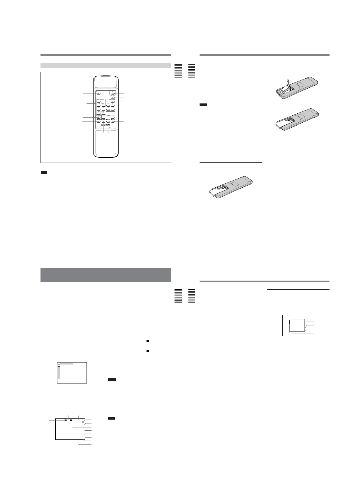
Location and Function of Parts
–∞40 30 20 10 0
dB
CH1 ||||||||||||||||||·|··· ·
CH2 |||||||||||||||||·|···· ·
CH3 ||||||||||||||||||||||| |
CH4 |||||||||||||·|········ ·
·· · · ··
3
1
2
DSR-45/45P
Supplied Remote Commander
1 EJECT button
2 SEARCH SELECT
buttons
3 Buttons for playing
at various speeds
4 PAUSE button
5 REW button
6 PLAY button
1 EJECT button
Note
When there is no cassette inside the unit, you cannot
open/close the cassette compartment, even if you press
this button.
In this case, press the EJECT button on the front panel
of the unit instead.
2 SEARCH SELECT buttons
Press these buttons to search for scenes using the
search function.
For details on the search function, see “Searching using the
search function” on page 37 (GB).
3 Buttons for playing at various speeds
You can play back a tape at normal speed or at a speed
other than normal with these buttons.
For details, see “Playing at various speeds” on page 37
(GB).
EJECT
qs 1 switch
qa DATA CODE button
×× × ×
VTR RMT-DS5
0 INDEX WRITE button
9 REC buttons
8 STOP button
7 FF button
4 PAUSE button
5 REW (rewind) button
6 PLAY button
7 FF (fast forward) button
8 STOP button
9 REC (record) buttons
When you press both these buttons at the same time,
the REC indicator and PLAY indicator on the front
panel light and recording begins.
Chapter 1 Overview25 (GB)
(Continued)
Chapter 1 Overview
0 INDEX WRITE button
Press this button during recording to mark an index.
For details on an index, see “Marking an index” on page 44
(GB).
Chapter 1 Overview
qa DATA CODE button
Press this button to display the data codes (recording
date/time, camera data).
For details on data codes, see “Displaying information
(data codes) recorded on a tape” on page 36 (GB).
qs 1 (on/standby) switch
Notes
•The command mode of the supplied Remote
commander is set to VTR4. You cannot change this
setting.
•Set COMMANDER on the OTHERS menu to
WIRELESS to enable the Remote Commander to
control the unit.
•In addition to the Remote Commander supplied with
the unit, the unit accepts signals from any Sony
Remote Commander whose command mode is set to
VTR4. If you want to disable the control from any
Remote Commander, set COMMANDER on the
OTHERS menu to CONTROL S.
•If the REMOTE/LOCAL switch is set to REMOTE,
the control of the Remote Commander is restricted by
the setting of LOCAL ENBL on the REMOTE menu.
Battery installation
1
Push and slide the lid to open.
26
(GB) Chapter 1 Overview
2
Install two size AA (R6) batteries (supplied) with
the correct polarity.
Be sure to install the
battery from the # side.
3
Replace the lid.
Notes on batteries
• Make sure that the battery orientation is correct when
inserting batteries.
• Do not mix an old battery with a new one, or mix
different types of batteries.
• If you do not intend to use the Remote Commander
for a long time, remove the batteries to avoid damage
from battery leakage. If the batteries have leaked,
remove them, wipe the battery compartment dry and
replace the batteries with new ones.
To remove the batteries
Remove the lid as step 1 and take out the batteries.
Displaying V arious Data
The unit can display various superimposed data items
on the built-in LCD monitor or on a monitor connected
to the MONITOR VIDEO jack.
To display various data items on the LCD monitor, set
the CHARACTER DISPLAY (LCD) selector to ON or
ON (BLACK BACK).
To display various data items on an external monitor,
set the CHARACTER DISPLAY (MONITOR OUT)
switch to ON.
You can select data items to be displayed using the
DISPLAY SELECT selector.
Menu screen
To display the menu screen, set the DISPLAY
SELECT selector to MENU. You can change or
confirm the menu item settings on this screen.
For details on the menu, see “Chapter 6 Adjusting and
Setting Through Menus” on page 76 (GB).
TC ⁄ UB SET
TC
TC PRESET
RMT
UB PRESET
CM
TC ⁄ UB IN
DISP
DV IN TC
V
TC MAKE
A
TC RUN
VTR
TC FORMAT
ETC
JOG TC OUT
Data screen
To display the data screen, set the DISPLAY SELECT
selector to DATA. You can confirm important
information for recording or playback, such as time
code or remaining tape time, on this screen.
1
N
%Z
DEW
DETECTED
TC
00:12:34:12
PHOTO –10
122min
SEARCH
NS 48K
DVCAM
DV IN
Displaying Various Data
1 Cassette memory indicator
This item is shown when a cassette with cassette
memory has been loaded. If the cassette is ejected
while data is being written on the cassette memory, the
indicator flashes.
2 Tape transport mode indicator
Displays the tape transport mode.
3 Time counter (time code/user bits/count value of
the counter) indicator
Displays the count value of the counter, time code, or
user bits. By setting the COUNTER SELECT selector
on the front panel, you can select the item to be
displayed.
When the time code is displayed,
In the drop frame mode, a period is displayed between
the minutes and seconds. (Example: 00:12.58:00)
When the user bits are displayed,
left.
When the count value of the counter is negative, “–”
appears as the first digit (leftmost digit). When that
value is positive, the first digit is blank.
The count value of the counter consists of seven digits.
If the self-diagnostic function is enabled, diagnostics
code numbers are displayed.
Notes
•The counter operates on a ±12-hour cycle. You
cannot make the counter operate on a 24-hour cycle.
•The count value of the counter consists of seven
digits. The leftmost digit is not displayed. (i.e.; If the
actual count value is “11:22:11:22,” the displayed
value will be “1:22:11:22.” ) However, the unit
recognizes that the hours value is 11.
4 Remaining tape time indicator
Displays the remaining tape time.
32
Note
4
When you insert a cassette in which the tape has been
5,6
rewound to the beginning, this indicator will not show
7
the remaining tape time. The remaining tape time is
8
PAL
displayed after the tape runs for a while.
9
q;
5 Search indicator
qa
Displays the search mode when you search for scenes
qs
using the Remote Commander or the DSRM-20 (not
supplied).
For details on the search function, see “Searching using the
search function” on page 37 (GB).
TC
appears to its left.
appears to their
UB
Chapter 1 Overview27 (GB)
Chapter 1 Overview
(Continued)
6 Index indicator
Displays INDEX MARK when an index has been
marked.
7 Caution indicator
Chapter 1 Overview
Displays a caution.
For details on cautions, see “Alarm Messages” on page 97
(GB).
8 PAL (DSR-45)/NTSC (DSR-45P) indicator
DSR-45: Appears for five seconds when you play
back a PAL formatted tape.
DSR-45P: Appears for five seconds when you play
back an NTSC formatted tape.
9 DVCAM/DV indicator
In the EE or recording mode, displays the recording
format selected in REC MODE on the VTR SET
menu. During playback, displays the recording format
of the picture.
0 Audio mode indicator
In the EE or recording mode, displays the audio mode
selected in AUDIO MODE on the AUDIO SET menu.
During playback or audio dubbing, displays the audio
mode recorded on the tape. When you input a signal to
the DV jack, displays the audio mode of that signal.
qa Input signal indicator
Displays the INPUT SELECT selector setting.
qs NS (Non standard) audio mode indicator
This item is shown when a tape recorded in the unlock
audio mode is played back or when an unlock mode
signal has been input to the DV jack. In EE mode,
when REC MODE in the VTR SET menu is set to DV
SP, this item is always shown.
For details on the unlock mode, see “Compatibility of
DVCAM and DV Format” on page 101 (GB).
28
(GB) Chapter 1 Overview
Audio screen
To display the audio screen, set the DISPLAY
SELECT selector to AUDIO. You can confirm or
adjust the audio levels and confirm the audio input
signal settings on this screen.
1 Audio levels
Displays the audio levels for each channel
independently. When the audio mode is FS32K, the
audio levels of four channels, channel 1 to 4, are
displayed. When the audio mode is FS48K, the audio
levels of channel 1 and 2 are displayed.
The unit detects the audio mode as follows.
In the playback mode: Detects the audio mode
recorded on the tape.
In the recording/EE mode: Detects the selected
audio mode in AUDIO MODE on the AUDIO
SET menu.
When the INPUT SELECT selector is set to DV
and a DV signal is being input: Detects the
audio mode of the signals being input. (The
setting of AUDIO MODE on the AUDIO SET
menu becomes invalid.)
In the EE, recording, or audio dubbing (only the audio
dubbing channel) modes, if the input levels exceed
0 dB, the portions of the meters that exceed 0 dB turn
to red. During playback, while DV signals are input or
the AUDIO INPUT switch is set to AUTO, those
portions of the levels meters do not turn to red.
2 Audio dubbing symbol
This symbol appears associated with a channel on
which you can dub sounds.
Appears when:
•a tape is being transported and pictures are displayed
on the LCD monitor or on an external monitor.
•the unit is in the stop mode, a signal other than DV is
selected, and you press the AUDIO DUB button.
1-5
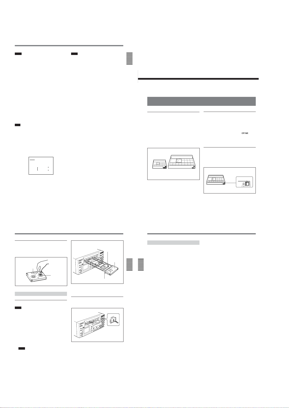
DSR-45/45P
Notes
•You can dub sounds only on a tape on which signals
are recorded in the 32 kHz audio mode (4 channels,
12 bit) and in the DVCAM format.
•You can select a pair of channels to dub sounds using
AUDIO DUB on the AUDIO SET menu.
•You cannot perform audio dubbing using a sound
signal input via the DV jack. This symbol does not
appear when DV signals are input.
3 Link symbol
If the AGC (Auto Gain Control) of a pair of channels
is linked, this symbol is placed between the channels.
In the EE mode, if AGC CH1, 2 on the AUDIO SET
menu is set to LINKED and the AUDIO INPUT
switch is set to AUTO, channels 1 and 2 can be linked
for AGC operation and for stereo sound where channel
1 is set for the left sound and channel 2 is set for the
right sound.
In the EE mode, if AGC CH3, 4 on the AUDIO SET
menu is set to LINKED and the AUDIO INPUT
switch is to AUTO, channels 3 and 4 can be linked for
AGC operation and for stereo sound where channel 3
is set for the left sound and channel 4 is set for the
right sound.
Note
When DV signals are input, the AGC does not
function and channels are not linked. This symbol does
not appear with a DV connection.
Fine audio levels screen
When the audio screen is displayed, pressing the FINE
(AUDIO) button displays the fine audio levels screen.
The screen is displayed only while you are pressing the
FINE (AUDIO) button. You can adjust the audio
recording levels precisely on this screen.
F I NE –22 –20 –18
CH1 |||||||||||······
CH2 ||||||||||·······
CH3 |||||||||||||||··
CH4 ||||||···········
The fine audio levels screen displays narrower audio
levels around the audio levels (–12/–18/–20 dB)
selected in REF LEVEL on the AUDIO SET menu.
dB
Notes
•Changing REF LEVEL on the AUDIO SET menu
does not change the audio gain of the unit. According
to the level of sounds you want to record, select an
appropriate gain by setting the INPUT LEVEL
selector on the rear panel. Then, adjust the audio
recording levels using the AUDIO REC LEVEL
control knobs.
•The standard output level of the AUDIO OUT
connectors of the unit is +4 dBu. This is equivalent to
–20 dB level for the full-bit maximum audio level
(–18 dB level for the DSR-45P). This value is fixed
and is not affected by the setting of REF LEVEL on
the AUDIO SET menu.
Chapter 1 Overview
Chapter 2 Playback and Recording
Notes on Video Cassettes
Usable cassettes
Use Standard-DVCAM cassettes or Mini-DVCAM
cassettes with this unit. The PDV-184 can record
programs for 184 minutes and the PDVM-40 can
record for 40 minutes (DVCAM format).
You can get the highest quality pictures with this
digital videocassette recorder using DVCAM cassettes.
Using other cassettes does not ensure sufficient
reliability. We recommend using DVCAM cassettes so
that you can record your one-time events in the highest
quality.
DVCAM cassetteMini DVCAM cassette
Playback and
Recording
Cassette memory
Cassette memory is an optional feature that is mounted
on some Standard DVCAM cassettes and Mini
DVCAM cassettes. When you record a program, the
recording date and time, and the programs’ position on
the tape are stored in the cassette memory so that you
can quickly locate the program later on.
cassette indicates that you can use the cassettes to store
up to 16 kbits of data. On this unit, you can use
cassettes on which up to 16 kbits of data can be stored.
To save a recording
To prevent accidental erasure of a recording, slide in
the REC/SAVE switch on the cassette so that the red
portion becomes visible. To record on a tape, slide out
the switch so that the red portion is hidden.
Chapter
REC/SAVE switch
Set to SAVE.
REC
SAVE
2
on a
Checking the tape for slack
Using a paper clip or a similar object, turn the reel
gently in the direction shown by the arrow. If the reel
does not move, there is no slack.
Paper clip, etc.
Reel
Inserting/Ejecting Cassettes
To insert a cassette
Notes
•Do not insert the cassette forcibly. The unit may be
damaged.
•Do not eject/load the cassette in a place subject to
light. The internal sensor of the unit may operate
incorrectly if too much light falls on the unit.
1
With the unit powered on, press the EJECT button.
The cassette compartment opens.
2
After checking the tape for slack, hold the cassette
so that the tape window is facing upward, then
insert it into the unit.
Notes
•When inserting a cassette, hold the back edge of
the cassette in the center and push it until the
cassette is inserted deep into the unit. If you hold
the ends, the cassette may not be loaded properly.
•If the cassette does not load or is loaded only
halfway, eject it once, then insert it again. In such
a case, if you insert the cassette forcibly, the
cassette may not be loaded properly or
malfunctions may occur.
•It takes a few seconds for the unit to recognize
the cassette and find the proper location on the
tape being loaded.
Chapter 1 Overview29 (GB)
Mini cassette
(Insert the mini cassette
into the center of the
cassette compartment.)
Standard
cassette
Tape window facing upward
The cassette is automatically loaded into the unit
and the cassette compartment closes.
To eject the cassette
1
With the unit powered on, press the EJECT button.
The cassette is unloaded and ejected.
2
Remove the cassette from the unit. Press the
EJECT button to close the cassette compartment.
Chapter 2 Playback and Recording31 (GB)
30
Notes on Video Cassettes
No compensation for contents of the
recording
Contents of the recording cannot be compensated for if
recording or playback is not successful due to a
malfunction of the unit, video tape, etc.
Copyright precautions
Chapter 2 Playback and Recording
On recording
Chapter 2 Playback and Recording
You cannot record any software having copyright
protection signals on this unit. If you start recording
protected video and audio signals, a warning appears
on the monitor screen and the unit stops recording.
During recording, if you change the INPUT SELECT
selector setting, the unit may mistakenly recognize that
a copyright protected signal has been input.
On playback
When you play back software having copyright
protected signals on this unit, you may not be able to
copy it onto other equipment.
Limitations caused by differences in format
The unit can record and play back tapes recorded in
DVCAM format. It can also record and play back
tapes recorded in DV format (SP mode).
However, due to differences in format, you may not be
able to play back or edit some tapes affected by
recording conditions of the tape (e.g., a tape originally
recorded in DV format is dubbed in DVCAM format).
For details, see “Compatibility of DVCAM and DV Format”
on page 101 (GB).
If a tape has both a portion recorded in the DVCAM
format and one recorded in the DV format (SP mode),
the following limitations are applied when you play
back the tape with this unit:
•The image may be distorted and noise may occur at
the point where the recording format changes on the
tape.
•The tape transport control buttons may be disabled
until the tape speed is stabilized.
Simple playback function for a tape recorded
using the PAL system (for the DSR-45) or the
NTSC system (for the DSR-45P)
The DSR-45 can play a PAL tape (the DSR-45P can
play an NTSC tape) recorded in the DVCAM format
or consumer DV format (SP mode only). This function
has the following limitations:
•The video signals are output only to the LCD monitor
and the MONITOR VIDEO output.
32
(GB) Chapter 2 Playback and Recording
Notes on Playback/Recording
(GB) Chapter 2 Playback and Recording
•The color system of the output video signal is that of
the signals recorded on the tape played back. You
cannot convert the signals into the other color system.
If you want to display the MONITOR VIDEO output,
you will need a video monitor able to handle the
color system recorded on the tape.
•The MONITOR VIDEO output is optimized and
adjusted for one color system (DSR-45: NTSC
system; DSR-45P: PAL system). If you play back a
tape recorded in the other color system, the levels and
phases of the video signal may not be correct.
•The outputs from the VIDEO OUT, S VIDEO OUT
and COMPONENT OUT connectors are muted.
•When the unit plays a tape recorded in the other color
system (i.e., PAL for the DSR-45, or NTSC for the
DSR-45P), the image, sound and time code may be
distorted for a while at the beginning and the end of
playback.
•The TC OUT connector outputs incorrect time code.
Do not use this time code.
•The unit cannot play back in synchronization with the
external sync signal.
•Noise reduction results for the luminance and
chrominance signals may differ between PAL
formatted tapes and NTSC formatted tapes.
•Even when the DSR-45 plays back a PAL formatted
tape (or the DSR-45P plays back an NTSC formatted
tape), you can control the basic tape transport
functions using a device connected to the RS-422A or
RS-232C connectors. However, any editing
operations attempted in this case are not guaranteed.
Limitations regarding the differences in color
systems
Except for the simple playback function for a tape
recorded in the other color system, this unit is not
compatible with any other color systems.
•This unit cannot record video signals of the other
color system.
•Inputting the other format video signals does not
output the EE pictures correctly. The video output
may be muted and some signals may not be
displayed.
•You may not be able to dub sound correctly from a
tape recorded in the other color system in this unit.
•If a tape has both NTSC and PAL formatted video
signals, the following limitations are applied when
you play that tape with this unit:
– The image may be distorted and noise may occur at
the point where the recording format changes on
the tape.
– The tape transport control buttons may be disabled
until the tape speed is stabilized.
1-6
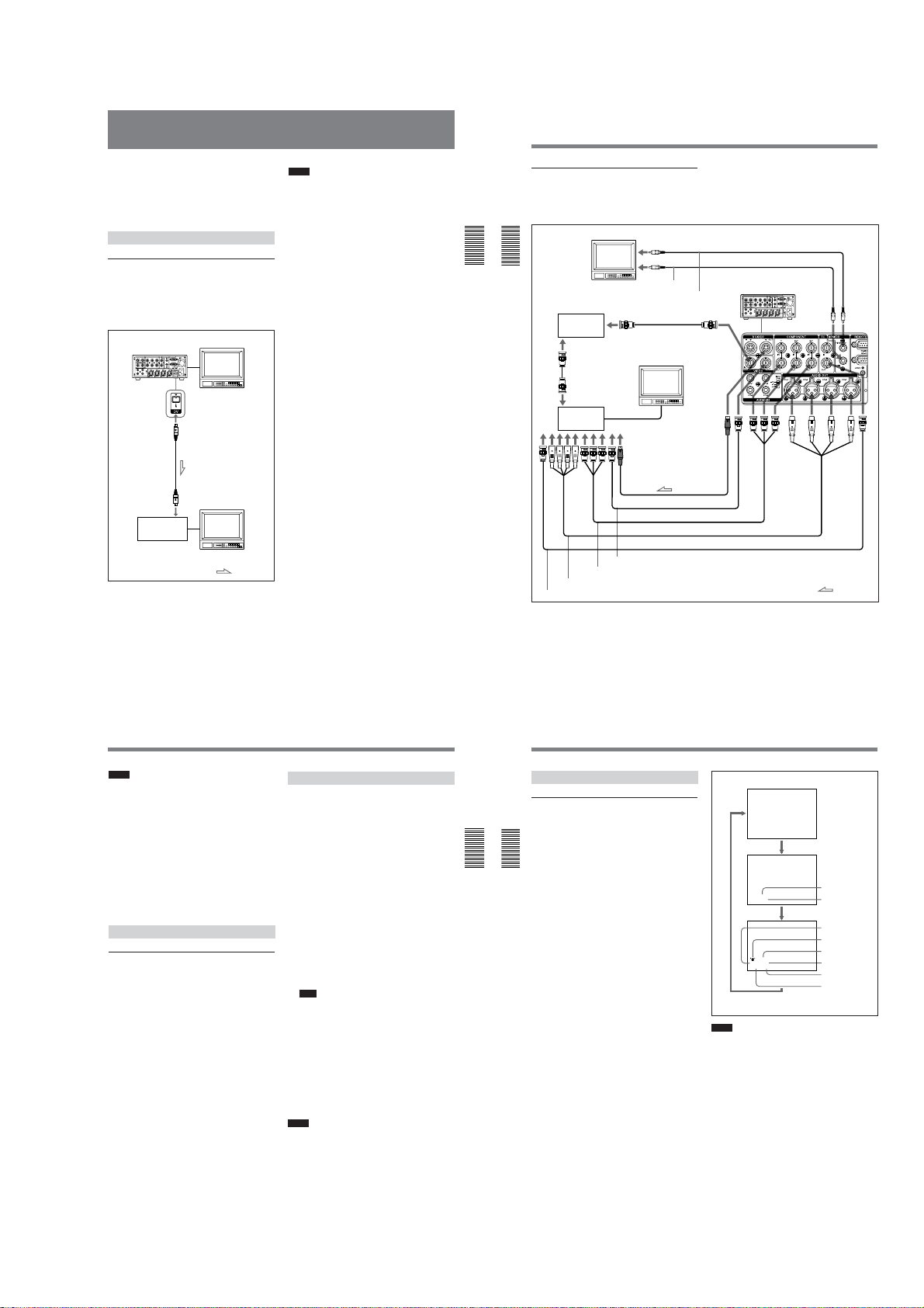
DSR-45/45P
Playback
This section describes the connections, settings and
operations necessary to perform playback on this unit.
The same settings and operations apply whether you
are using the unit as part of an editing system, for
dubbing, or as a stand-alone videocassette player.
Connections for Playback
To digital video equipment with a DV jack
The video and audio signals are sent with hardly any
degradation, enabling high-quality recording. The
signal flow is automatically detected so you do not
need to make separate connections for input and
output.
DSR-45/45P (rear panel)
i.LINK cable
(DV cable)
(not supplied)
DV jack
Digital video
equipment with a
DV jack
Monitor
Monitor
: Signal flow
Notes
•With the DV connection, data codes (recording date/
time, camera data) recorded on the source tape are
transmitted to the recorder. As a result, when you
play back a recorded tape on this unit and press the
DATA CODE button on the Remote Commander, the
same data codes as those recorded on the source tape
are displayed on the monitor screen.
•The external lock function of this unit only supports
the standard sync signals. With the DV connection,
set EXT SYNC on the VIDEO SET menu to OFF to
prevent malfunction resulting from noise, etc.
For details on the VIDEO SET menu, see “VIDEO SET
menu” on page 86 (GB).
•If no picture appears via the DV jack, disconnect the
i.LINK cable (DV cable), then reinsert it straight.
•When connecting a device that has a 6-pin DV jack to
this unit, first, connect the plug of the cable to the 6pin DV jack.
•If the unit is connected to a device equipped with a 6pin DV jack, when you intend to disconnect or
reconnect the DV cable, turn off the device and pull
out the plug of its power cord from the AC outlet
beforehand. If you connect or disconnect the DV
cable while the device is connected to the AC outlet,
high-voltage current (8 to 40 V) is output from the
DV jack of the device to this unit, which may cause a
malfunction.
•If you connect the input connectors of this unit to the
output connectors of a recorder or that of a monitor, a
humming noise may be generated or the image may
be distorted. If these phenomena occur, perform one
of the following:
–Set DV EE OUT on the VTR SET menu to OFF.
–Set the INPUT SELECT selector to a position
where a signal is not currently being input.
–Disconnect the cables.
Chapter 2 Playback and Recording33 (GB)
Playback
To video equipment without a DV jack
You can connect this unit to video equipment without
a DV jack. Use this unit as follows.
The following illustration shows an example of a
Chapter 2 Playback and Recording
Chapter 2 Playback and Recording
Connect one of the following as a video cable: video
cable (3BNC y 3BNC), S-video cable, 75 Ω coaxial
cable.
34
Monitor
Reference video
signal generator
Audio input
Time code input
(GB) Chapter 2 Playback and Recording
B.B.OUT
75 Ω coaxial cable
(not supplied)
REF.VIDEO
Recorder
Component input
B.B.OUT
S-video input
Video input
configuration for dubbing a tape with its time code in
the externally-synchronized playback mode. In this
configuration, the recorder is a VCR equipped with
XLR input connectors.
Phono jack cable (not supplied)
Audio input
Monitor
S-video cable (not supplied)
75 Ω coaxial cable (not supplied)
Video cable (3BNC y 3BNC) (not supplied)
Audio cable (XLR y XLR) (not supplied)
75 Ω coaxial cable (not supplied)
Phono jack cable (not supplied)
Video input
DSR-45/45P (player)
(rear panel)
: Signal flow
Notes
•If you connect the input connectors of this unit to the
output connectors of a recorder or that of a monitor, a
humming noise may be generated or the image may
be distorted. If these phenomena occur, perform one
of the following:
– Set EE/PB SEL on the DISPLAY SET menu to PB.
– Set the INPUT SELECT selector to a position
where a signal is not currently being input.
–Disconnect the cables.
•Text data (time code, warnings, menus, etc.) are
superimposed only on the MONITOR VIDEO output.
•To play back in synchronization with the reference
video (black burst) signal, set EXT SYNC on the
VIDEO SET menu to ON.
Settings for Playback
Preparation on the player (this unit)
1
Power on the video monitor, then set the monitor’s
input switch according to the signals input.
2
Set up the recorder.
For details, refer to the instruction manual of the
recorder.
3
Turn this unit on.
Playback Procedures
This section describes the procedures used to play
back a tape and send signals to another VCR. For
details on the procedures required when using a
computer as a recorder, refer to the instruction manual
of your computer or the user’s manuals of the software
installed on it.
When controlling this unit from an editing controller
connected to the RS-232C or RS-422A connectors, see
“Chapter 3 Using the Unit as a Player in an Editing
System” on page 46 (GB).
1
After checking the tape for slack and confirming
that the q indicator is off, hold the cassette so
that the tape window is facing upward, then insert
it into this unit.
The cassette is automatically loaded into the unit.
For details on checking the tape for slack, see “Notes
on Video Cassettes” on page 30 (GB).
For details on inserting a cassette, see “To insert a
cassette” on page 31 (GB).
Note
Do not insert the cassette forcibly. The unit may be
damaged.
2
Press the PLAY button on this unit.
This unit starts playback.
To stop playback
Press the STOP button on this unit.
To pause playback
Press the PAUSE button on this unit.
Notes
•When this unit plays back a part of the tape where the
recording format has been changed between the
DVCAM format and the DV format, the picture and
sound may be distorted.
•The unit can play back only tapes recorded in the
DVCAM format or in the SP mode of the DV format.
Playback
Displaying information (data codes)
recorded on a tape
If you record on a tape using a Sony digital camcorder
(DSR-200/200P, 200A/200AP, PD100/PD100P,
PD100A/PD100AP, PD150/PD150P, 250/250P, etc.),
data codes can be recorded on the tape.
Chapter 2 Playback and Recording
The data codes consist of recording date/time and
Chapter 2 Playback and Recording
camera data (the shutter speed, SteadyShot, iris, white
balance, program AE mode, gain, date and time).
You can check these data items during playback on
this unit.
First, set the DISPLAY SELECT selector to DATA. If
the selector is set to other than DATA, the data codes
are not displayed.
Press the DATA CODE button on the Remote
Commander during playback.
Each time you press the DATA CODE button, the
display changes in sequence as follows: no data code
t recording date/time t camera data t no data
code .....
Also, using DATA CODE on the DISPLAY SET
menu, you can select a data item to be displayed.
For details on the DISPLAY SET menu, see “DISPLAY SET
menu” on page 85 (GB).
Playback Functions
No indicator
Recording
date/time
2000 12 25
19 : 20 : 30
Camera
data
MANUAL
10000 ATW
F 1.6 0 dB
Notes
•If the data codes were not recorded, “- - -” appears
instead.
•This unit cannot record camera data. Camera data
items show the settings of a tape recorded by a digital
camcorder (DSR-200/200P, 200A/200AP, PD100/
PD100P, PD100A/PD100AP, PD150/PD150P, 250/
250P, etc.).
•Some of the camera data items displayed by this unit
are different from those shown on the digital
camcorder.
Date
Time
Shutter speed
SteadyShot
Program AE
White balance
Gain
Iris
Chapter 2 Playback and Recording35 (GB)
1-7
36
(GB) Chapter 2 Playback and Recording
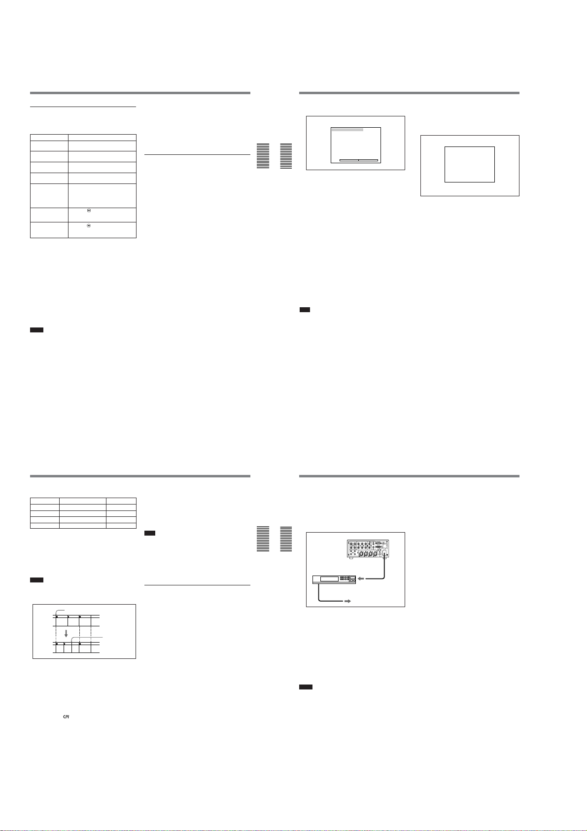
DSR-45/45P
Playback
Playing at various speeds
You can enjoy playback functions using the Remote
Commander.
Playback options
Play at 1/10 of
normal speed
Play at 1/3 of
normal speed
Play at normal
speed
Play at twice the
normal speed
Play frame by
frame
Fast forward the
tape while
monitoring pictures
Rewind the tape
while monitoring
pictures
To change playback direction
Press the FRAME c/C buttons during normal
playback or when playing at various speeds.
To play back in the forward direction, press the C
button; in the backward direction, press the c
button.
To hear the sound while playing at various
speeds
If you want to hear the sound when playing at various
speeds, set JOG AUDIO on the AUDIO SET menu to
ON.
For details on the AUDIO SET menu, see “AUDIO SET
menu” on page 88 (GB).
Notes
•When the command mode of a Sony device / remote
commander is set to VTR4;
– if you press the ×1/3 button on the supplied Remote
Commander while pointing it toward a Sony device
other than this unit, the playback speed may turn to
1/5 of normal speed.
– if you press the ×1/5 button on a remote
commander while pointing it toward this unit, the
playback speed will turn to 1/3 of normal speed.
Operation
Press × 1/10 button during playback.
Press × 1/3 button during playback.
Press × 1 button during playback.
Press × 2 button during playback.
Press FRAME c/C buttons
during pause.
If you keep pressing one of these
buttons, playback continues, frame by
frame.
button during normal
Press the
playback or when playing at various
speeds.
button during normal
Press the
playback or when playing at various
speeds.
•If the unit keeps playing at 1/10 of normal speed in
forward or reverse for more than one minute, the unit
will begin to play back forward at normal speed.
•Even if you set JOG AUDIO on the AUDIO SET
menu to ON, sound may not be output or may be
interrupted depending on differences in the recording
formats (DVCAM/DV) or the condition of the tape.
Searching using the search function
There are four kinds of search available on this unit:
– Searching for the beginnings of recordings: Index
search
– Searching for the boundaries of recorded tape by
title: Title search*
– Searching for a point on the tape where the recorded
date changes: Date search
– Searching for scenes recorded in the photo mode
with a digital camcorder: Photo search
*A function available only on a cassette with cassette
memory
To search for scenes, use the supplied Remote
Commander or the Remote Control Unit (DSRM-20,
not supplied).
To search with the cassette memory
If you set CM SEARCH on the CM SET menu to ON
and the cassette has cassette memory, the scenes are
listed in the chronological order in which they were
made. You can search using this chronological list.
If the cassette does not have cassette memory, you
cannot search for scenes in chronological order.
For details on the CM SET menu, see “CM SET menu” on
page 81 (GB).
1
Press the SEARCH SELECT button on the Remote
Commander or the SEARCH MODE button on the
Remote Control Unit (DSRM-20, not supplied) to
select the search type: INDEX, TITLE, DATE or
PHOTO SEARCH.
(Continued)
Chapter 2 Playback and Recording37 (GB)
Chapter 2 Playback and Recording
Chapter 2 Playback and Recording
2
To search without cassette memory
When you use a cassette without cassette memory, the
unit searches in the order of the actual positions of the
scenes, regardless of the setting of CM SEARCH on
the CM SET menu.
On a cassette with cassette memory, when you want to
perform searches with this procedure, set CM
SEARCH on the CM SET menu to OFF.
For details on the CM SET menu, see “CM SET menu” on
page 81 (GB).
Note
Title search is not available when searching a cassette
without cassette memory.
38
A chronological list appears on the monitor screen.
When selecting INDEX SEARCH
INDEX SEARCH
CH
1 0 0 / 2 / 2 8 1 : 0 0 LINE
2 0 0 / 3 / 7 1 2 : 5 9 LINE
3 0 0 / 3 / 1 1 3 : 0 5 LINE
4 0 0 / 5 / 5 1 9 : 0 0 LINE
5 0 0 / 7 / 3 1 0 : 1 5 LINE
6 0 0 / 1 0 / 2 8 1 2 : 2 0 LINE
v
q
The displayed forms of the date and time can be
changed by setting DATE DISP and TIME DISP on the
DISPLAY SET menu.
For the DSR-45P, “PROG” is displayed instead of
“CH.”
For details on the DISPLAY SET menu, see “DISPLAY
SET menu” on page 85 (GB).
Press the . or > button to select a scene.
The unit starts searching and when it locates the
scene, begins playback. During Photo search, the
unit turns to the playback pause mode.
(GB) Chapter 2 Playback and Recording
1
Press the SEARCH SELECT button on the Remote
Commander or the SEARCH MODE button on the
Remote Control Unit (DSRM-20, not supplied) to
select the search type.
When selecting INDEX SEARCH
INDEX 00
SEARCH
(The search screens are displayed only on
the Data screen.)
2
Press the . or > button repeatedly to locate
the scene you want.
Each time you press the . or > button, the
unit searches for the previous or next search point.
When a search point is located, its number is
indicated on the monitor screen.
The unit starts searching backwards or forwards
until the number comes to zero, then plays back the
scene. During Photo search, the unit turns to the
playback pause mode.
How signals are recorded
There are four different signal types, one for each
search method; index, title, date and photo signals.
They are recorded by the digital camcorder (DSR-200/
200P, 200A/200AP, PD100/PD100P, PD100A/
PD100AP, PD150/PD150P, 250/250P, etc.). However,
the type of signal recorded and where it is recorded (on
the tape or in the cassette memory) depend on whether
the cassette has cassette memory or which type of
video equipment is used for recording. Please note that
if the signals for a certain search type are not recorded,
you cannot perform that type of search. For details on
the signals used for a particular type of search, refer to
the instruction manual of the recorder.
Signals that can be recorded on this unit are as follows.
Signals for In cassette memory On tape
Index search* Yes Yes
Title search No No
Date search No Yes
Photo search No No
* If AUTO INDEX on the VTR SET menu is set to ON and the
unit is in the stop mode, when you start recording, the unit
automatically marks a signal for Index search. If AUTO INDEX
is set to OFF, the unit does not mark it.
pressing
the INDEX button on the unit or the INDEX WRITE
button on the Remote Commander marks a signal for Index
search regardless of the AUTO INDEX setting.
Notes
•If you record another program over the beginning of
the search signals, you will not be able to locate the
original program.
Search signal
ABC
During recording,
If D is recorded
over the beginning
of B...
B cannot be
searched for
CADB
•You cannot add search signals after recording.
To add a search signal for Auto Repeat, start
recording from the point where you want to add it.
•When recording on this unit, signals for Index search
do not have information on the day of the week.
•Searching may not be done correctly if the tapes were
not recorded on Sony-brand digital video equipment.
About the cassette memory
•A tape with the
using the 16 kbit cassette memory, you can store up
to 135 search signals. (The number changes
depending on the memory capacity of various
cassettes. It also changes depending on the data size
combination of index, title, date, photo, and tape label
data stored on a tape.) This unit is capable of storing
and retrieving up to 16 kbits of information in
cassette memory.
mark has cassette memory. When
•To locate scenes that did not fit in the cassette
memory, or to locate scenes in order of their position
on the tape, set CM SEARCH on the CM SET menu
to OFF. You can use the same procedure to search for
a scene on a tape without cassette memory.
For details on the CM SET menu, see “CM SET menu” on
page 81 (GB).
Note
The number of search signals that you can record is
limited by the cassette memory space available when
you start recording. When you use a previously
recorded tape for repeated recordings, make more
memory space available by erasing unwanted items
using ITEM ERASE or ERASE ALL on the CM SET
menu before you start recording.
Automatically playing back a tape
repeatedly (Auto Repeat)
This unit can repeat the playback of all or a part of the
tape.
1
Set the TIMER selector on the front panel of this
unit to REPEAT.
2
Press the REW button. (If the tape is already
rewound, press the PLAY button.)
The unit rewinds the tape to its beginning, and
starts playback automatically. The unit repeats the
playback from the beginning to the first index (if
there is no signal for Index search on the tape, to
the next unrecorded portion; if there is no
unrecorded portion, to the end of the tape).
(Continued)
Chapter 2 Playback and Recording39 (GB)
Playback
Auto Repeat using an external AC timer
If you connect an external AC timer (not supplied) to
this unit, you can repeat playback automatically at a
preset time.
1
Chapter 2 Playback and Recording
Chapter 2 Playback and Recording
2
3
Notes
•The unit cannot detect a signal for Index search or an
unrecorded portion within 20 seconds of the
beginning of the playback.
•When you intend to turn the unit off, press the STOP
button on this unit to stop the tape transport operation
beforehand. If you turn the unit off while a tape is
running, for example, by using an AC timer, the unit
or the tape may be damaged.
•The editing software used on the digital non-linear
editing system may mark an index signal on a tape
itself. Therefore, if you use a tape on which signals
transmitted from a digital non-linear editing
controller are recorded or a copy tape made from one,
using digital dubbing, Auto Repeat may not be
performed correctly.
40
Connect this unit to an external AC timer (not
supplied).
DSR-45/45P (rear panel)
AC timer
to an AC outlet
Set the TIMER selector on the front panel of this
unit to REPEAT.
Set the starting time on the external AC timer.
At the preset time, the power of this unit turns on,
and after a few seconds (no more than 30), Auto
Repeat playback starts automatically. The unit
repeats the playback from the beginning to the first
index (if there is no signal for Index search on the
tape, to the next unrecorded portion; if there is no
unrecorded portion, to the end of the tape).
(GB) Chapter 2 Playback and Recording
To stop Auto Repeat
Press the STOP button on this unit.
To release the Auto Repeat mode
Set the TIMER selector on the front panel to OFF.
1-8
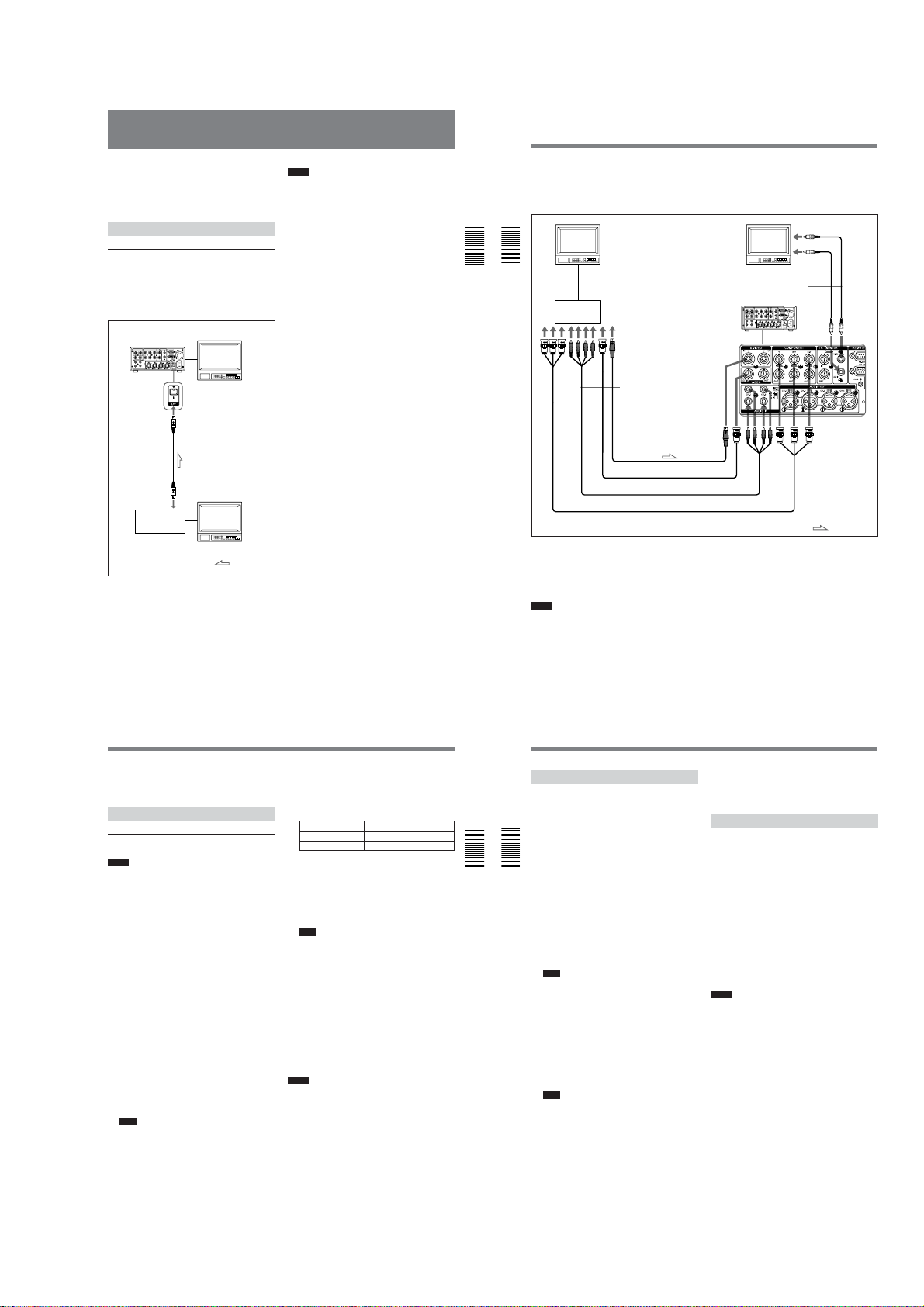
DSR-45/45P
Recording
This section describes the connections, settings and
operations necessary to perform recording on this unit.
The same settings and operations apply whether you
are using the unit for dubbing or as a stand-alone
recorder.
Connections for Recording
To digital video equipment with a DV jack
The video and audio signals are sent with hardly any
degradation, enabling high-quality recording. The
signal flow is automatically detected so you do not
need to make separate connections for input and
output.
DSR-45/45P (rear panel)
i.LINK cable
(DV cable)
(not supplied)
DV jack
Digital video
equipment with a
DV jack
Monitor
Monitor
: Signal flow
Notes
•With the DV connection, the sound is recorded in the
same audio recording mode as that of the source tape.
To record in a different audio recording mode from
the source tape, use the analog connection instead.
•With the DV connection, data codes (recording date/
time, camera data) recorded on the source tape are
transmitted to the recorder (this unit). As a result,
when you play back a recorded tape on this unit and
press the DATA CODE button on the Remote
Commander, the same data codes as those recorded
on the source tape are displayed on the monitor
screen. However, the contents of the cassette memory
are not transmitted. If you want to transmit the
contents of the cassette memory, use the duplicate
function.
•If no picture appears via the DV jack, disconnect the
i.LINK cable (DV cable), then reinsert it straight.
•When connecting a device that has a 6-pin DV jack to
this unit, first, connect the plug of the cable to the 6pin DV jack.
•If the unit is connected to a device equipped with a 6pin DV jack, when you intend to disconnect or
reconnect the DV cable, turn off the device and pull
out the plug of its power cord from the AC outlet
beforehand. If you connect or disconnect the DV
cable while the device is connected to the AC outlet,
high-voltage current (8 to 40 V) is output from the
DV jack of the device to this unit, which may cause a
malfunction.
•If you connect the output connectors of this unit to
the input connectors of a player or that of a monitor, a
humming noise may be generated or the image may
be distorted. If these phenomena occur, perform one
of the following:
– Set DV EE OUT on the VTR SET menu to OFF.
– Set the INPUT SELECT selector to a position
where a signal is not currently being input.
–Disconnect the cables.
Chapter 2 Playback and Recording41 (GB)
Recording
To video equipment without a DV jack
You can connect this unit to video equipment without
a DV jack. Use this unit as a recorder as follows.
Chapter 2 Playback and Recording
Chapter 2 Playback and Recording
Connect one of the following as a video cable: video
cable (3BNC y 3BNC), S-video cable, or 75 Ω
coaxial cable.
Use a conversion cable for the audio connection,
depending on types of audio output connectors on the
player (see page on 23 (GB)).
Notes
•During recording, analog input signals can be output
simultaneously from the DV jack for backup. Set DV
42
Monitor
Player
S-video output
Video output
Audio output
Component output
S-video cable (not supplied)
75 Ω coaxial cable (not supplied)
Audio cable (phono jack) (not supplied)
Video cable (3BNC y 3BNC) (not supplied)
(GB) Chapter 2 Playback and Recording
Monitor
DSR-45/45P (recorder)
(rear panel)
EE OUT on the VTR SET menu to ON.
For details on the VTR SET menu, see “VTR SET menu”
on page 90 (GB).
•If you connect the output connectors of this unit to
the input connectors of the player, a humming noise
may be generated or the image may be distorted. If
these phenomena occur, set the INPUT SELECT
selector to a position where a signal is not currently
being input, or disconnect the cables.
Audio input
Video input
Phono jack cable
(not supplied)
Phono
jack cable
(not
supplied)
: Signal flow
•Distorted signals (e.g., when played back at a speed
other than normal) may not be recorded or may be
distorted.
Settings for Recording
Preparation on the recorder (this unit)
Notes
•Before recording, set the date and time on the unit so
that the recording time can be written into the search
signal. You can set the date and time by setting
CLOCK SET on the OTHERS menu.
For details on the OTHERS menu, see “OTHERS menu”
on page 92 (GB).
•Editing may not be possible with a signal that is
copyright protected.
1
Power on the video monitor, then set the monitor’s
input according to the input signals.
2
Set up the player to play back a tape.
For details, refer to the instruction manual of the
player.
3
Turn this unit on.
4
Select an input signal by switching the INPUT
SELECT selector on this unit.
DV: to record input signals from the DV jack
S VIDEO: to record input signals from the S
VIDEO IN connector
VIDEO: to record input signals from the VIDEO
IN REF.IN connector
COMPONENT: to record input signals from the
COMPONENT IN connector
Note
Do not change the selector setting during
recording. Otherwise, noise is output to the picture
and sound and that portion will not be recorded
properly.
5
Select the audio mode. (With a DV connection,
skip this step.)
Select the desired mode by setting AUDIO MODE
on the AUDIO SET menu.
Audio mode Set the menu to
4-channel mode FS32K
2-channel mode FS48K
For details on the AUDIO SET menu, see “AUDIO SET
menu” on page 88 (GB).
6
Set the INPUT LEVEL selector on the rear panel
properly according to the audio level of the player.
7
Select the audio recording level adjustment mode
using the AUDIO INPUT switch.
Note
You cannot adjust the recording level if you record
signals input via the DV jack.
8
If necessary, adjust the audio recording level by
turning the AUDIO REC LEVEL control knobs.
You can adjust the recording level with the
AUDIO REC LEVEL control knobs if you have
selected MANU in step 7. While looking at the
audio level meters on the LCD monitor, turn the
AUDIO REC LEVEL control knobs to adjust the
recording level. Adjust the audio recording level so
that it does not exceed 0 dB when the audio signal
is at its maximum. If the recording level exceeds
0 dB, the recorded sound will be distorted.
Notes
•In the DVCAM format, there are two audio modes,
with either two channels at FS48K or four channels at
FS32K. It is not possible to select other modes (for
example with two channels at FS32K).
•During recording, you cannot change the audio mode.
•If you intend to dub a sound on the tape after it has
been recorded, set AUDIO MODE on the AUDIO
SET menu to FS32K (4-channel mode) before
recording.
For details on the AUDIO SET menu, see “AUDIO SET
menu” on page 88 (GB).
Recording
This section describes the procedures used to record
signals sent from another VCR to this unit. For details
on the procedures required when using a computer as a
player, refer to the instruction manual of your
computer or the user’s manuals of the software
installed on it.
Chapter 2 Playback and Recording
1
Chapter 2 Playback and Recording
2
3
To stop recording
Press the STOP button on this unit.
To pause recording
Press the PAUSE button on this unit.
Recording Procedures
After checking that the REC/SAVE switch on the
cassette is set to REC, checking the tape for slack
and confirming that the q indicator is off, hold
the cassette so that the tape window is facing
upward, then insert it into this unit.
The cassette is automatically loaded into the unit
and the tape will be ready to record.
For details on the REC/SAVE switch and checking the
tape for slack, see “Notes on Video Cassettes” on page
30 (GB).
For details on inserting a cassette, see “To insert a
cassette” on page 31 (GB).
Note
Do not insert the cassette forcibly. The unit may be
damaged.
Press the playback button on the player.
The player starts playback.
On this unit, press the PLAY button while holding
the REC button down.
The unit starts recording. If AUTO INDEX on the
VTR SET menu is set to ON, the index is marked.
Note
When you do not want to mark an index at the
beginning of the recording, set AUTO INDEX on
the VTR SET menu to OFF.
For details on the VTR SET menu, see “VTR SET
menu” on page 90 (GB).
To start recording using the Remote Control
Unit (DSRM-20, not supplied)
On the Remote Control Unit, press the PLAY button
while holding the REC button down.
Recording Functions
Marking an index
By pressing the INDEX button on the unit or the
INDEX WRITE button on the Remote Commander
during recording, you can mark an index signal at any
place on the tape. The index signal is inserted for five
seconds. If you mark an index at the scene you want to
search for, you can easily find the scene later.
If AUTO INDEX on the VTR SET menu is set to ON,
the index signal is marked automatically when the unit
in the stop mode starts recording.
While the index is being marked, the “INDEX
MARK” indicator appears for about seven seconds on
the Data screen (see page 27 (GB)).
If you use a cassette with cassette memory, the index
will also be marked in the cassette memory.
Notes
•You cannot mark a new index while the “INDEX
MARK” indicator is being displayed.
•If you record on a portion of the tape where an index
has been marked, the index will be erased. You
cannot delete just an index while keeping the image
or sound.
•You cannot mark an index during playback,
duplicating or audio dubbing operations. The INDEX
button and the INDEX WRITE button are disabled in
these operations.
•The cassette memory space available limits the
number of indexes that you can mark. When you use
a previously recorded tape for repeated recordings,
make more memory space available by erasing
unwanted items using ITEM ERASE or ERASE ALL
on the CM SET menu before you start recording.
To use an index during playback
You will need the Remote Commander or the Remote
Control Unit (DSRM-20, not supplied).
For details on the playback functions using the Remote
Commander, see “Searching using the search function” in
“Playback Functions” on page 37 (GB).
Chapter 2 Playback and Recording43 (GB)
1-9
44
(GB) Chapter 2 Playback and Recording
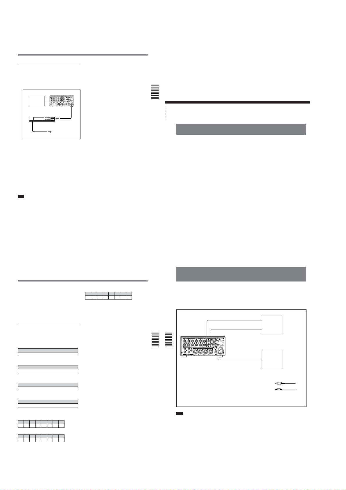
DSR-45/45P
AC timer recording
By connecting this unit to an external AC timer (not
supplied), you can start recording at a preset time.
1
Connect this unit to an external AC timer (not
supplied).
Recording
source
(external tuner,
etc.)
AC timer
2
Insert a tape for recording.
3
Set the INPUT SELECT selector of this unit to
select the input signal.
4
Set the TIMER selector on the front panel of this
unit to REC.
5
Set the timer-on time on the connected AC timer.
At the preset time, the power of this unit turns on
automatically and recording starts after a few
seconds (no more than 30). Set the timer allowing
a margin for the recording to start. You do not
need to press the REC button.
Note
When you intend to turn the unit off, press the STOP
button on this unit to stop the tape transport operation
beforehand.
If you turn the unit off while a tape is running, for
example, by using an AC timer, the unit or the tape
may be damaged.
DSR-45/45P (rear panel)
VIDEO IN REF. IN
to an AC outlet
If the tape ends before the recording source
stops operation
The tape stops.
To stop recording during timer recording
Press the STOP button on this unit.
To release the AC timer recording mode
Set the TIMER selector on the front panel of this unit
to OFF.
Chapter 2 Playback and Recording45 (GB)
Chapter 2 Playback and Recording
Chapter 3 Using the Unit as a Player in an Editing System
Notes on Usage in the Editing System
If you use the unit in an editing system, the following
functions are limited.
Notes on general
•When using the RS-422A/232C connectors to
connect this unit to other equipment, you cannot
place the unit as a recorder.
•This unit is not equipped with a synchronization
function. Adjust the edit timing with the editing
controller, and set sync grade to Preroll & Play.
•To make the unit comply with a command sent from
an editing controller to locate a scene, set FF/REW
SPD on the VTR SET menu to SHUTTLEMAX.
•Except when editing with the RS-422A connection, if
the unit has been in the pause mode for the period
specified in the menu, the unit will go into the tape
protection mode.
•When you control this unit from an editing controller
connected to the RS-422A connector:
– if the TIMER selector is set to REPEAT, and the
tape reaches its end point by fast-forwarding using
the FF button, jog dial control via the editing
controller is not available.
– if the tape reaches its beginning or end using the
REW or FF button, the unit turns to playback pause
mode at a point a few seconds from its beginning or
end.
46
(GB) Chapter 3 Using the Unit as a Player in an Editing System
Chapter
Using the Unit as a
Player in an Editing
System
•The TIMER selector setting has higher priority than
the REMOTE/LOCAL switch setting. In an editing
system, set the TIMER selector to OFF.
•Even if the REMOTE/LOCAL switch is set to
REMOTE, the Remote Commander may function
depending on the setting of LOCAL ENBL on the
REMOTE menu. If you want to disable the Remote
Commander, set COMMANDER on the OTHERS
menu to CONTROL S.
Notes on editing
•When you control this unit from an editing controller
connected to the RS-422A/232C connector in the
editing system, editing via a DV connection is less
accurate than editing via an analog connection.
•This unit is not equipped with the first edit function.
•Since this unit does not support CTL, if the time code
recorded on the tape is out of sequence or the tape has
a blank portion between recorded portions, you may
not be able to use it for editing. In such a case, adjust
the editing IN point.
3
•When the COUNTER SELECT selector on the front
panel of this unit is set to COUNTER, the value
determined by calculation based on the time code is
displayed. The value is a simple approximation.
Therefore, if you intend to use this unit as a player in
the editing system, set the COUNTER SELECT
selector to TC and also set the edit mode (EDIT
REFERENCE) of the editing controller to time code
(TC).
Settings on editing controller
When connecting an editing controller, make the
following settings, according to the model used.
FXE-100/120
Set the VCR device constants as follows:
123456789101112131415
80 31 00 96 05 05 0A 8A 0A 08 FE 00 80 5A FF
FXE-100P/120P
Set the VCR device constants as follows:
123456789101112131415
81 31 00 7D 05 05 0A 8A 0A 08 FE 00 80 5A FF
BVE-600/2000 (NTSC model)
Set the VCR device constants as follows:
123456789101112131415
80 31 00 96 05 05 0A 8A 0A 09 FE 00 80 5A FF
BVE-600/2000 (PAL model)
Set the VCR device constants as follows:
123456789101112131415
81 31 00 7D 05 05 0A 8A 0A 09 FE 00 80 5A FF
RM-450/450CE
Set the DIP switches as follows:
Left switch
76543210
OFF – – OFF – – – –
Right switch (RM-450)
76543210
OFF – OFF ON OFF OFF ON ON
Right switch (RM-450CE)
76543210
ON – OFF ON OFF OFF ON ON
If the edit timing is out of adjustment, change the
setting of items 0 to 2 of the right switch.
Connections for Digital Non-linear Editing
The unit can be connected to an editing controller via
DV jacks to configure a digital non-linear editing
system.
The following figure shows a connection diagram for
non-linear editing system in which this unit serves.
MONITOR
DSR-45/45P
Chapter 3 Using the Unit as a Player in an Editing System
Chapter 3 Using the Unit as a Player in an Editing System
If the editing software used has the capability to
output the time code as well as the video or audio
signals from the digital non-linear editing controller
to this unit, and you intend to record the time code,
set DV IN TC on the TC/UB SET menu of this unit
to EXTERNAL.
For details on the TC/UB SET menu, see “TC/UB
SET menu” on page 78 (GB).
Note
If the unit is connected to a device equipped with a 6pin DV jack, when you intend to disconnect or
reconnect the DV cable, turn off the device and pull
out the plug of its power cord from the AC outlet
beforehand. If you connect or disconnect the DV cable
while the device is connected to the AC outlet, highvoltage current (8 to 40 V) is output from the DV jack
of the device to this unit, which may cause a
malfunction.
VIDEO
MONITOR
AUDIO
DV
For connection of the editing controller and its peripheral
devices, refer to the instruction manual of the editing
controller and that of the editing software you use.
Edit functions are specified by the editing software. For
details on the editing methods used, refer to the instruction
manual of the editing software.
1
Video input
1
Audio input
2
DV jack
1 Phono jack cable (not supplied)
2 i.LINK cable (DV cable) (not supplied)
Video monitor
Editing controller
Chapter 3 Using the Unit as a Player in an Editing System47 (GB)
1-10
48
(GB) Chapter 3 Using the Unit as a Player in an Editing System
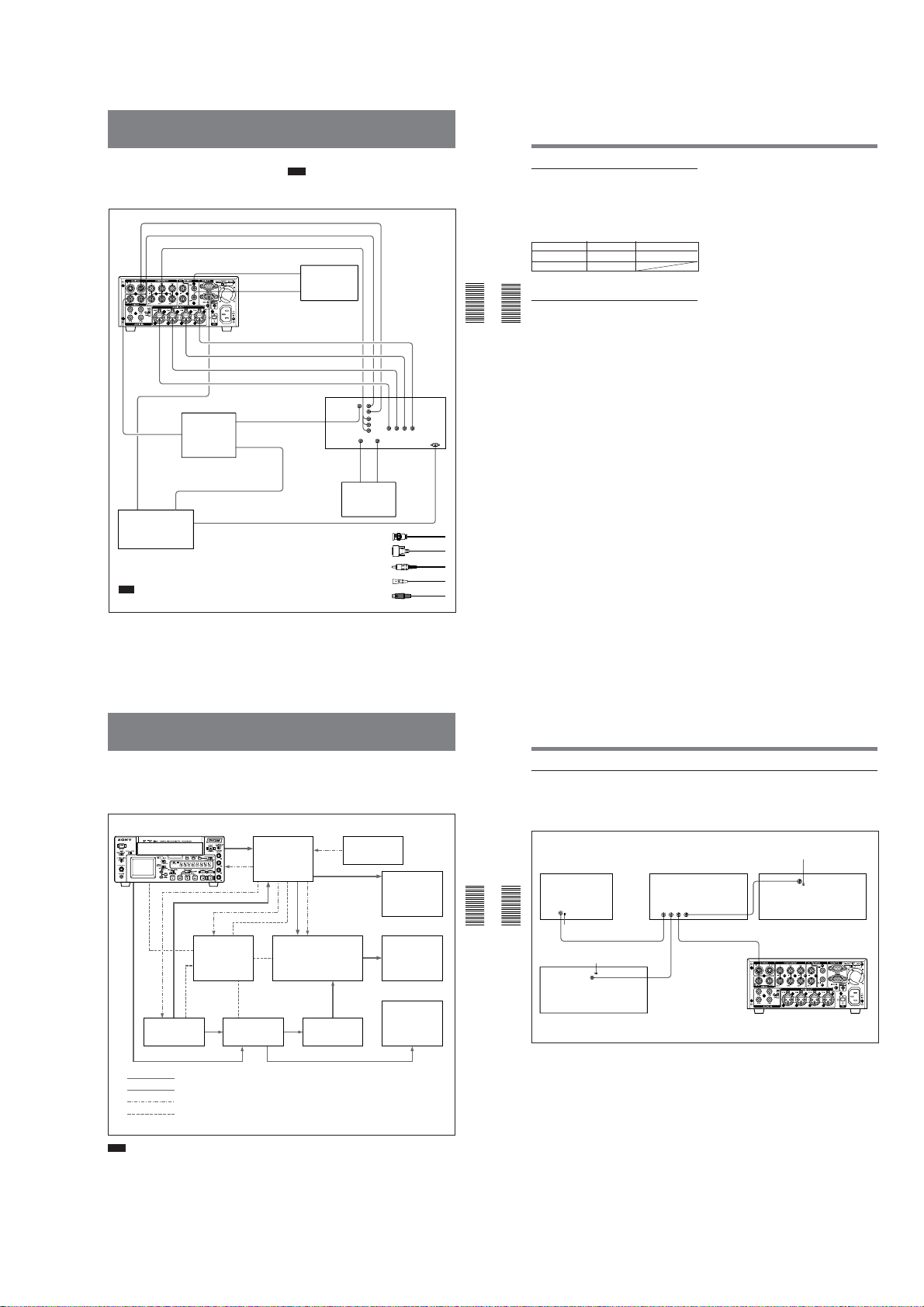
DSR-45/45P
Connections for a Cut Editing System
The following figure shows a cut editing system
configuration that uses this unit as the player.
For details of connecting devices other than the DSR-45/
45P, refer to the instruction manual of each device.
S VIDEO OUT 5
VIDEO OUT 1
COMPONENT OUT
DSR-45/45P (player)
MONITOR VIDEO
MONITOR
AUDIO
VIDEO IN
REF.IN
1
2
REF.VIDEO
OUT
Editing controller
Connect one of the following as a video cable:
video cable (3BNC y 3BNC), S-video cable, or
75 Ω coaxial cable.
Note
Use a recorder equipped with a synchronization
function.
AUDIO OUT CH-4 4 AUDIO IN CH-4
AUDIO OUT CH-3 4 AUDIO IN CH-3
AUDIO OUT CH-2 4 AUDIO IN CH-2
AUDIO OUT CH-1
RS-422A
REF.VIDEO INPLAYER
REF.VIDEO
OUT
Reference
video signal
generator
REF.VIDEO OUT
1
RECORDER 2
Note
The preroll time of the setting on the editing controller
is required to be more than five seconds.
S VIDEO IN
1
3
3
VIDEO IN
Y, R-Y, B-Y IN
Video
input
Source video
Audio
monitor
input
4 AUDIO IN CH-1
Recorder
REF.VIDEO
1
IN
MONITOR
Audio input Video input
1 75 Ω coaxial cable (not supplied)
2 9-pin remote control cable (not supplied)
3 Phono jack cable (not supplied)
4 Cable with XLR connectors (not supplied)
5 S-video cable (not supplied)
AUDIO
31
Main video
monitor
MONITOR
VIDEO OUT
REMOTE
Connections for a Cut Editing System
Settings on the Editing Control Unit
For details on the settings of the Editing Control Unit,
refer to “Adjusting Edit Timing” on page 56 (GB).
Settings on the DSR-45/45P (player) and a
recorder
Switch DSR-45/45P Recorder
REMOTE/LOCAL REMOTE REMOTE
REMOTE RS-422A
For details, refer to the instruction manual of the recorder.
About reference video signals
Chapter 3 Using the Unit as a Player in an Editing System
•In order to provide stable video and audio signals for
Chapter 3 Using the Unit as a Player in an Editing System
analog editing, it is necessary for the built-in time
base corrector (TBC) to operate correctly. To ensure
this, input a reference video signal synchronized with
the video signal to the VIDEO IN REF.IN connector.
•Set EXT SYNC on the VIDEO SET menu to ON.
Chapter 3 Using the Unit as a Player in an Editing System49 (GB)
Connections for an A/B Roll Editing System
The following is an example of a configuration of an
A/B roll editing system using the DSR-45/45P and a
recorder.
The purpose of the following figure is to clearly
DSR-45/45P (Player 1)
1
CH-
CH-
1/2
3/4
MIN MAX
Player 2 Audio mixer Delay unit
CH-1
CH-2
CH-3
CH-4
Editing controller
Video signal
Audio signal
Reference video signal
Control signal
indicate the flow of signals among the component
devices in this system. The specific connections and
the recorder settings for this system are described on
the following pages.
Reference video
Switcher
Recorder
a) When using a switcher, the phase of the video signals
processed by the switcher is delayed, which means that a
delay unit must be connected between the audio mixer’s
output and the recorder’s audio input.
signal generator
a)
Main video
monitor
Source video
monitor
Audio monitor
system
50
(GB) Chapter 3 Using the Unit as a Player in an Editing System
Connections for an A/B Roll Editing System
Reference video signal connection
When you perform editing, be sure to use a reference
video signal.
For details on reference video signals, see “About reference
video signals” on page 50 (GB).
Editing controller
REF.
Chapter 3 Using the Unit as a Player in an Editing System
Chapter 3 Using the Unit as a Player in an Editing System
REF. VIDEO IN 75 Ω
VIDEO
termination switch: ON
IN
REF. VIDEO IN 75 Ω
termination switch: ON
Player 2
Use 75 Ω coaxial cables for all of these connections.
REF. VIDEO IN
If you intend to make this unit perform playback
synchronized with an external reference video signal,
set EXT SYNC on the VIDEO SET menu to ON.
REF. VIDEO IN 75 Ω
termination switch: ON
REF. VIDEO IN
Switcher
1234
BLACK BURST OUT
VIDEO IN REF.IN
DSR-45/45P (Player 1)
Recorder
Note
Use a recorder equipped with a synchronization
function.
Chapter 3 Using the Unit as a Player in an Editing System51 (GB)
1-11
52
(GB) Chapter 3 Using the Unit as a Player in an Editing System
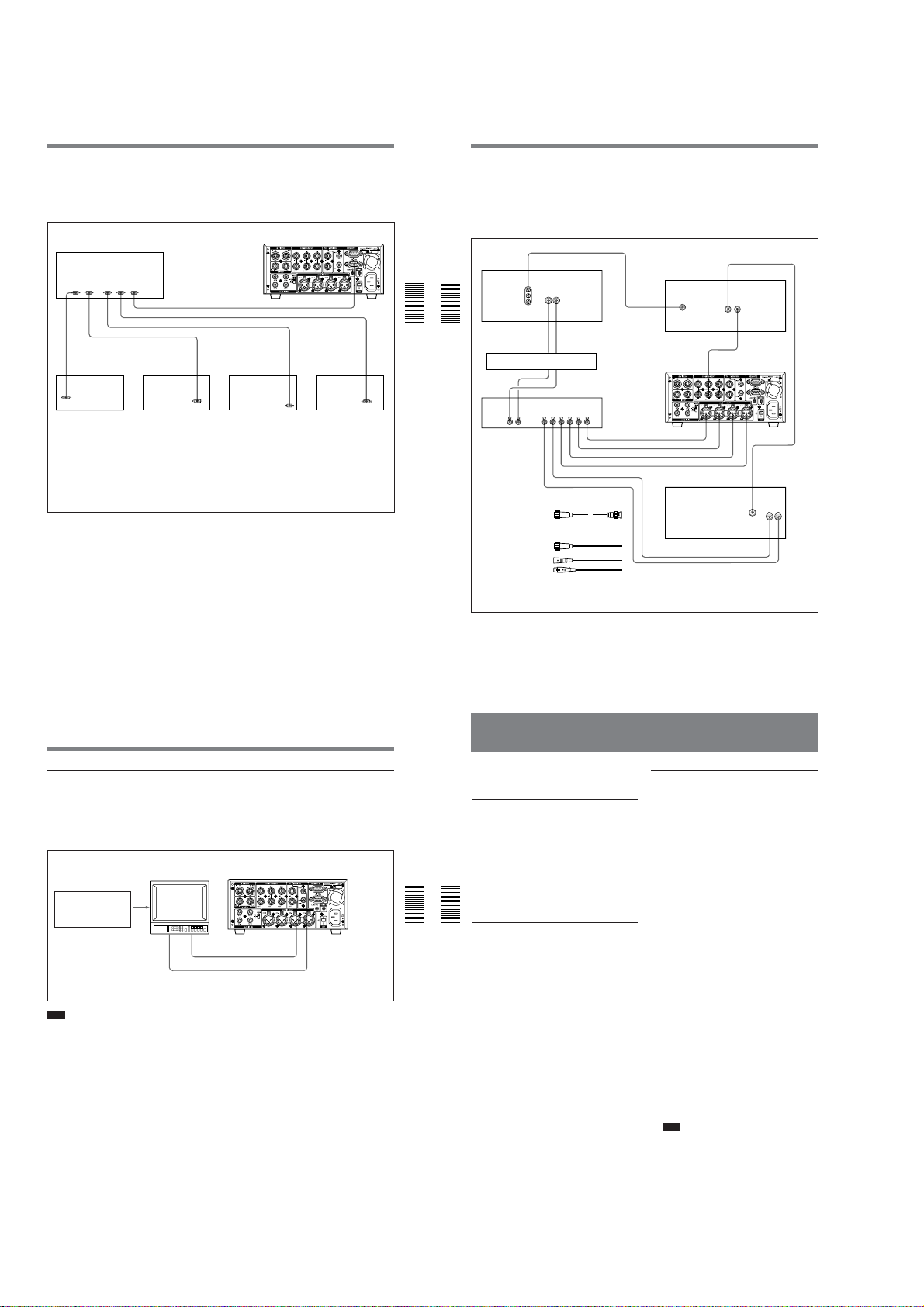
DSR-45/45P
Connections for an A/B Roll Editing System
Control signal connections
The following shows an example of the control signal
connections needed to enable the editing controller to
control all other A/B roll editing system devices.
Editing controller
9-pin remote control cable
SWITCHER
PLAYER 2
RECORDER
PLAYER 1
9-pin remote control cable
9-pin remote control cable
MIXER
Audio mixer Switcher Recorder
To control the unit from an editing controller, set the
REMOTE/LOCAL switch of this unit to REMOTE.
Furthermore, if you use an RS-422A connection, set the
remote selector of this unit to RS-422A.
a) Use an optional 9-pin remote control cable.
a)
a)
a)
DSR-45/45P (Player 1)
REMOTEEDITOR
RS-422A
Player 2
REMOTE
Video/audio signal connections
The following shows an example of video/audio signal
connections in an A/B roll editing system. In this
example, analog component signals are used as the
video signals and XLR 3-pin connectors are used as
audio output connectors.
Chapter 3 Using the Unit as a Player in an Editing System
Chapter 3 Using the Unit as a Player in an Editing System
AUDIO IN
Delay unit
3
LINE OUT LINE OUT
1 12-pin y 3×BNC cable
(not supplied) (Consult
your Sony dealer about
this cable.)
2 12-pin dubbing cable
(not supplied)
3 Cable with XLR
connectors (not supplied)
COMPONENT VIDEO IN
(Y, R–Y, B–Y)
Recorder
CH-2
CH-1
3
3
CH-2 OUTCH-1 OUT
CH-2 INCH-1 IN
3
Audio mixer
56
1234
PGM OUT
COMPONENT OUT
3
3
3
3
3
3
Switcher
DSR-45/45P
(Player 1)
AUDIO OUT CH-1
CH-2
CH-3
CH-4
Player 2
For details of the video/audio input, connecting cables, and
audio mode settings, refer to the instruction manuals for the
devices used.
VIDEO INPUT
COMPONENT INPUT
VIDEO INPUT
COMPONENT INPUT
1
COMPONENT OUT
Y, R-Y, B-Y OUT
AUDIO OUTPUT
COMPONENT
OUTPUT
CH-1
2
CH-2
Connection of a video monitor
Set up the following connections to enable monitoring
of video and audio signals on a video monitor. In
addition to video signals, you can check time data, the
DSR-45/45P’s operation mode, alarm messages, and
other information displayed as text on the monitor
screen.
Video monitor
75 Ω termination switch: ON
(or attach a 75 Ω terminator)
Input switches: Set
according to the type of input
signals.
Video input
Note
When you want to monitor the edited tape, use the
monitor output connector on the recording VCR.
Audio input
Phono jack cable (not supplied)
Chapter 3 Using the Unit as a Player in an Editing System53 (GB)
DSR-45/45P
MONITOR
MONITOR
VIDEO
AUDIO
54
(GB) Chapter 3 Using the Unit as a Player in an Editing System
Adjusting Edit Timing
For details, refer to the instruction manuals of the editing
controller you use.
Using this unit as a player with the RM450/450CE
1
Set the SYNCHRO selector to ON.
2
Set item number 3 of the SYSTEM PRESET right
switch to OFF (it is set to OFF at factory).
Setting this to OFF adjusts the synchronization of
the recorder.
3
Execute the LEARN function.
Chapter 3 Using the Unit as a Player in an Editing System
Using this unit as player 1 with the PVE-
Chapter 3 Using the Unit as a Player in an Editing System
500
When using this unit as player 2, the relevant menu
item is indicated in ( ).
1
Set Sync Edt of SEtUP-10 to OFF in the SETUP
menu.
2
Set P1 dELAY (P2 dELAY) of SEtUP-13 (SEtUP-
14) to LEArn in the SETUP menu.
3
Set rEC Sync of SEtUP-15 to On in the SETUP
menu.
4
Set P1 Sync (P2 Sync) of SEtUP-16 (SEtUP-17) to
OFF in the SETUP menu.
5
Execute the LEARN function.
Using this unit as a player 1 with the FXE120/120P
•When using this unit as player 2, the relevant menu
item is indicated in ( ).
•When using an FXE-100/100P that has been
upgraded with an FXE-KIT1, the relevant menu item
is indicated in [ ].
1
Display item 104 [301] SYNC GRADE in the
SETUP menu, and set PLAYER1 (PLAYER2) to
PREROLL & PLAY.
2
Display item 301 (302) [401 as player 1, 402 as
player 2] DEVICE TYPE PLAYER1 (DEVICE
TYPE PLAYER2) in the SETUP menu, and set the
VCR device constants.
For details on device constants, see page 47 (GB).
3
Execute the LEARN function.
If the edit timing is out of adjustment, follow the
instruction given in “Adjusting the IN point”
below.
Adjusting the IN point
If the actual edited point does not accurately coincide
with the preset editing point, perform a fine adjustment
of the edit timing using the SETUP menu of the editing
controller. This improves the editing accuracy.
1
Display item 301 (302) [401 as player 1, 402 as
player 2] DEVICE TYPE PLAYER1 (DEVICE
TYPE PLAYER2) in the SETUP menu, and
change it from DISABLE to ENABLE.
2
Repeat the editing process several times and check
the shift of the editing point; that is, count the
number of frames to be adjusted.
Note
The editing results may differ between the
DISABLE and ENABLE settings of SETUP menu
item 301 (302) [401 as player 1, 402 as player 2].
Be sure to check the editing results after changing
the setting to ENABLE.
Chapter 3 Using the Unit as a Player in an Editing System55 (GB)
1-12
56
(GB) Chapter 3 Using the Unit as a Player in an Editing System
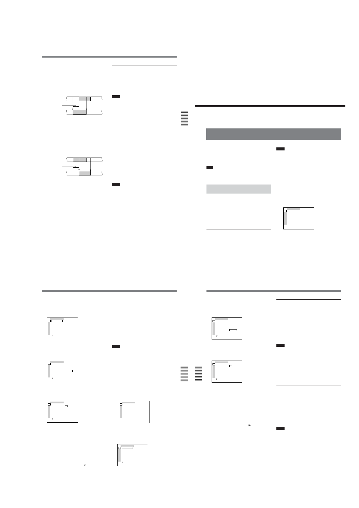
3
TC ⁄ UB SET
TC PRESET
UB PRESET
TC ⁄ UB IN
DV IN TC
TC MAKE
TC RUN
TC FORMAT
JOG TC OUT
RETURN
TC
RMT
CM
DISP
V
A
VTR
ETC
00 00 00 00
RESET
PRESET
RETURN
TC ⁄ UB SET
TC PRESET
UB PRESET
TC ⁄ UB IN
DV IN TC
TC MAKE
TC RUN
TC FORMAT
JOG TC OUT
RETURN
TC
RMT
CM
DISP
V
A
VTR
ETC
OOOO
00 00 00 00
oooo
SET
CANCEL
Change SETUP menu item 301 (302) [401 as
player 1, 402 as player 2] from BYTE 01 to BYTE
10, and calculate the adjustment value.
How to calculate the adjustment value
If the actual IN point shifts forward to the IN point
preset on the player;
Preset editing points
Adjustment value
Actual editing points
08 (default setting) + number of frames obtained in
step 2
Example: To adjust 5 frames
08 + 05 = 0D
The adjustment value is calculated in hexadecimal.
If the actual IN point shifts backward to the IN
point preset on the player;
Preset editing points
Adjustment value
Actual editing points
08 (default setting) – number of frames obtained in
step 2
Example: To adjust 5 frames
08 – 05 = 03
4
Perform a trial editing process and confirm the
results of the adjustment.
Repeat steps 3 and 4 until the best possible result
is obtained.
IN point
IN point
IN point
IN point OUT point
OUT point
OUT point
OUT point
Using this unit as a player with the BVE600
1
Set the sync grade (menu 2) to mode number 4,
PREROLL & PLAY in auxiliary mode.
2
Set the VCR device constants in the setting mode.
For details on device constants, see page 47 (GB).
Notes
•If FF/REW SPD on the VTR SET menu of this unit is
set to FF/REW when the unit rewinds or fastforwards the tape, the time code may not be displayed
on the editing controller. In this case, set FF/REW
SPD to SHUTTLEMAX.
For details on FF/REW SPD, see page 90 (GB).
•When editing, use a time code.
•Depending on the type of device you are using as a
recorder, the actual edited point may not accurately
coincide with the preset editing point. In this case,
adjust the VCR device constants of the editing
controller (CONST8 (Start Delay) in BYTE-2 in
BLOCK-2).
Using this unit as a player with the BVE2000
1
Set SYNC GRADE (synchronous accuracy) in the
AUX mode to PREROLL & PLAY.
2
Display VTR CONSTANT or OPTION VTR
CONSTANT on the setup menu, and set the VCR
device constants.
Notes
•It is advisable to set JOG DIAL RESPONSE in
SYSTEM CONFIGURATION on the setup menu to
LOW.
•When editing, use a time code.
Chapter 3 Using the Unit as a Player in an Editing System57 (GB)
Setting the Time Code and User Bits
Chapter 3 Using the Unit as a Player in an Editing System
Setting the Time Code and User Bits
This unit can set, display, record and play back the
Chapter 4 Setting the Time Code and Adjusting the Video Signals
time code and user bits. The unit can also output the
time code read from the tape as an analog (LTC) signal
when it is played back at normal speed, and receive an
external analog time code (LTC) signal.
Note
The items other than JOG TC OUT on the TC/UB SET
menu can be set only when you record in DVCAM
format.
Using the Internal Time Code
Generator
You can set the initial time code value generated by
the internal time code generator. In addition, you can
set the user bits to record data such as the date, time,
scene number, reel number, or other useful
information. The time data settings are set by using the
menu.
For details on the menu, see “Chapter 6 Adjusting and
Setting Through Menus” on page 76 (GB).
To set the initial time code value
This section describes how to set the time code’s initial
value.
58
(GB) Chapter 4 Setting the Time Code and Adjusting the Video Signals
DSR-45/45P
Chapter
4
Setting the Time Code
and Adjusting the
Video Signals
Notes
•The time code can be set only in a DVCAM format
recording. It cannot be set in a DV format recording.
Make sure to set REC MODE on the VTR SET menu
to DVCAM.
•To set the initial time code value, you need to set TC/
UB IN on the TC/UB SET menu to INTERNAL and
TC MAKE to PRESET beforehand.
For details on TC/UB IN and TC MAKE, see “TC/UB SET
menu” on page 78 (GB).
•While you are setting the initial time code value using
a device connected to the RS-422A/232C connector,
TC PRESET on the TC/UB SET menu is disabled.
1
Display the menu on the monitor.
For details on displaying the menu, see “Operating the
Menus” on page 76 (GB).
TC ⁄ UB SET
TC
TC PRESET
RMT
UB PRESET
CM
TC ⁄ UB IN
DISP
DV IN TC
V
TC MAKE
A
TC RUN
VTR
TC FORMAT
ETC
JOG TC OUT
(The TC FORMAT submenu is only available on
the DSR-45.)
2
Press the J/j buttons to select TC/UB SET, then
press the EXEC button.
The following menu appears.
TC ⁄ UB SET
TC
TC PRESET
00:00:00:00
RMT
UB PRESET
CM
TC ⁄ UB IN
DISP
DV IN TC
V
TC MAKE
A
TC RUN
VTR
TC FORMAT
ETC
JOG TC OUT
RETURN
3
Press the J/j buttons to select TC PRESET, then
press the EXEC button.
The following menu appears.
TC ⁄ UB SET
TC
TC PRESET
00:00:00:00
RMT
UB PRESET
CM
TC ⁄ UB IN
RESET
DISP
DV IN TC
PRESET
V
TC MAKE
RETURN
A
TC RUN
VTR
TC FORMAT
ETC
JOG TC OUT
RETURN
4
Press the J/j buttons to select PRESET, then
press the EXEC button.
The following menu appears.
TC ⁄ UB SET
TC
TC PRESET
OOOO
RMT
UB PRESET
00:00:00:00
CM
TC ⁄ UB IN
oooo
DISP
DV IN TC
SET
V
TC MAKE
CANCEL
A
TC RUN
VTR
TC FORMAT
ETC
JOG TC OUT
RETURN
5
Set the first two digits. Press the J/j buttons to
select the number, then press the EXEC button.
6
Repeat step 5 to set the other digits.
7
Press the J/j buttons to select SET, then press the
EXEC button.
The initial time code value is set and the menu
display returns to that of step 2.
8
Press the J/j buttons to select RETURN, then
press the EXEC button.
The menu display returns to that of step 1.
To cancel the time code setting
Select CANCEL in step 7, then press the EXEC
button.
To reset the time code
Select RESET in step 4, then press the EXEC button.
To set the value of the user bits
You can set the user bits as eight-digit hexadecimal
values (base 16) to have the date, time, scene number,
and other information inserted into the time code track.
Notes
•The user bits can be set only in a DVCAM format
recording. They cannot be set in a DV format
recording.
•To set the user bits, you need to set TC/UB IN on the
TC/UB SET menu to INTERNAL beforehand.
For details on TC/UB IN, see “TC/UB SET menu” on page
78 (GB).
•While you are setting the user bits using a device
connected to the RS-422A/232C connector, UB
PRESET on the TC/UB SET menu is disabled.
1
Display the menu on the monitor.
For details on displaying the menu, see “Operating the
Menus” on page 76 (GB).
TC ⁄ UB SET
TC
TC PRESET
RMT
UB PRESET
CM
TC ⁄ UB IN
DISP
DV IN TC
V
TC MAKE
A
TC RUN
VTR
TC FORMAT
ETC
JOG TC OUT
2
Press the J/j buttons to select TC/UB SET, then
press the EXEC button.
The following menu appears.
TC ⁄ UB SET
TC
TC PRESET
00:00:00:00
RMT
UB PRESET
CM
TC ⁄ UB IN
DISP
DV IN TC
V
TC MAKE
A
TC RUN
VTR
TC FORMAT
ETC
JOG TC OUT
RETURN
(Continued)
Chapter 4 Setting the Time Code and Adjusting the Video Signals59 (GB)
Setting the Time Code and User Bits
3
Press the J/j buttons to select UB PRESET, then
press the EXEC button.
The following menu appears.
4
Press the J/j buttons to select PRESET, then
press the EXEC button.
The following menu appears.
Chapter 4 Setting the Time Code and Adjusting the Video Signals
Chapter 4 Setting the Time Code and Adjusting the Video Signals
5
Set the first two digits. Press the J/j buttons to
select the number, then press the EXEC button.
6
Repeat step 5 to set the other digits.
7
Press the J/j buttons to select SET, then press the
EXEC button.
The user bits are set and the menu display returns
to that of step 2.
8
Press the J/j buttons to select RETURN, then
press the EXEC button.
The menu display returns to that of step 1.
To cancel the user bits setting
Select CANCEL in step 7, then press the EXEC
button.
To reset the user bits
Select RESET in step 4, then press the EXEC button.
60
(GB) Chapter 4 Setting the Time Code and Adjusting the Video Signals
1-13
To select the time code/user bits to be
recorded on the tape
You can set the time code and user bits to be recorded
on the tape by setting TC/UB IN on the TC/UB SET
menu.
INTERNAL: Uses the internal time code/user bits.
TC&UB EXT: Uses the external time code/user bits.
TC EXT: Uses the external time code and internal
user bits.
UB EXT: Uses the internal time code and external
user bits.
Notes
•This unit has a DV jack. The time code input or
output is different when you connect the unit to an
external device via this DV jack or via another input/
output connector.
For details, see “DSR-45/45P time codes” on page 63
(GB).
•The time code output from this unit has some
restrictions.
For details, see “Notes on the Time Codes” on page 64
(GB).
To select the time code to be recorded
when DV signals are recorded in DVCAM
format
Set DV IN TC on the TC/UB SET menu to select
whether to record the internal time code or an external
one.
INTERNAL: Records the time code internally
generated.
EXTERNAL: Records the time code with video and
audio signals input via the DV jack.
Notes
•When this item is set to EXTERNAL, the setting of
TC/UB IN on the TC/UB SET menu turns to invalid.
The time code input via the DV jack and the user bits
set in UB PRESET are recorded.
•When you set REC MODE on the VTR SET menu to
DV SP, this item cannot be used. Even if this item is
set to EXTERNAL, when you set REC MODE on the
VTR SET menu to DV SP, the setting becomes
invalid and the unit records the internal time code.

DSR-45/45P
Synchronizing the Time Codes
Synchronizing the Time Codes
•When this item is set to EXTERNAL, the INPUT
SELECT selector on the front panel is set to DV, and
no signal is input via the DV jack, or the software of
the editing controller does not output a time code, if
you start recording, bars (– –:– –:– –:– –) are
recorded as time code. At the point that the input of a
signal begins, the time code of that signal will be
recorded.
•When this item is set to EXTERNAL, if you input
time code to the DV jack that is not continuous or
does not advance correctly, the value of the recorded
or displayed time code may not be equal to the actual
value of the input one. If you use a tape with this
problem, you may not be able to perform search or
edit, depending on the devices you use.
To set the time code when the recording
starts
Set TC MAKE on the TC/UB SET menu to select the
time code to be recorded when recording starts.
REGEN: The time code value is set to continue the
time code from the time code already recorded on
the tape. If you start recording from a blank
portion of the tape, the time code starts from
00:00:00:00.
PRESET: The time code starts from the value set in
TC PRESET on the TC/UB SET menu.
To set the advancement mode
Set TC RUN on the TC/UB SET menu to switch the
advancement mode (counting up).
REC RUN: Time code advances only while
recording.
FREE RUN: Time code advances even when the
unit is not recording. This mode is used to set the
current time as the initial time code value, or to
synchronize the internal time code to an external
one.
Notes
•If you set the advancement mode to FREE RUN, the
time code will be updated by the internal clock while
the unit’s power is off. The time code may have been
delayed or advanced somewhat if you turn on the unit
power again, play back a tape, or set the INPUT
SELECT selector to DV.
•If the internal backup battery charge is exhausted, the
time code of the FREE RUN setting will be
initialized. The internal backup battery is fully
charged if you connect the power to the unit for about
8 hours. A fully charged internal battery can run for
about two weeks.
To set the frame mode (DSR-45 only)
Set TC FORMAT on the TC/UB SET menu to switch
the frame mode.
AUTO: Automatically sets the mode in accordance
with the loaded tape.
If nothing is recorded on the tape, the mode is set
to the non-drop frame mode. If the unit cannot
read the frame mode correctly from the tape, the
unit will use the mode that was set in the last
position it was able to read correctly on the tape. If
you remove the cassette, the mode of the last
position it was able to read correctly is cleared and
the mode is set to the non-drop frame mode. If TC
MAKE is set to PRESET, the mode is also set to
the non-drop frame mode.
DF: Selects the drop frame mode.
NDF: Selects the non-drop frame mode.
Note
In a DV format recording, the drop-frame mode is
used automatically.
To switch the time code output when
playing at various speeds (JOG)
Set JOG TC OUT on the TC/UB SET menu to control
the time code output from the TC OUT connector
when the tape is played at various speeds.
OFF: Does not output the time code.
ON: Outputs the time code.
Note
Continuous time code is output only when the tape is
played at normal speed. When the unit is in the jog or
search mode, discontinuous time code is output.
You can synchronize the internal time code generator
of the unit with an external time code signal (LTC).
Connecting to the Time Code
Generator
Time code generator
to time
code
output
connector
(not supplied)
Chapter 4 Setting the Time Code and Adjusting the Video Signals
Chapter 4 Setting the Time Code and Adjusting the Video Signals
DSR-45/45P (rear panel)
75 Ω coaxial cable
: Signal flow
To synchronize the internal time code to
an external time code
1
Set the INPUT SELECT selector to other than DV.
2
Input an external time code (LTC) signal to the TC
IN connector of the unit.
3
Set TC/UB IN on the TC/UB SET menu to
TC&UB EXT or TC EXT.
4
Set TC RUN on the TC/UB SET menu to FREE
RUN.
The internal time code generator locks onto the
external time code and starts advancing. Once the
internal time code generator has become
synchronized in this way, you can disconnect the
external time code input and this unit will maintain
the time code.
Notes
•This unit has a DV jack. The time code input/output
with a DV connection is different from that with
other analog connections.
For details, see “DSR-45/45P time codes” on page 63
(GB).
•The time code output from this unit has some
restrictions.
For details, see “Notes on the Time Codes” on page 64
(GB).
To confirm external synchronization
Before you start recording, check that the internal time
code is synchronized with the external time code.
Press the STOP button to turn the unit to the stop
mode, then press the REC button.
Look at the time counter display and check that the
time code value displayed there matches the external
time code value.
Chapter 4 Setting the Time Code and Adjusting the Video Signals61 (GB)
DSR-45/45P time codes
This unit has a DV jack. The time code output and
recorded on the tape differs as shown below when the
INPUT SELECT selector is set to DV and when it is set
to other than DV.
When DV IN TC is set to INTERNAL
INPUT SELECT
Playback
EE
TC/UB IN
menu
INTERNAL
TC&UB EXT
TC EXT
UB EXT
selector
DV
S VIDEO
VIDEO
COMPONENT
(Except DV)
DV
S VIDEO
VIDEO
COMPONENT
(Except DV)
Mode
Playback
Audio dubbing
Playback at various
a)
speeds
b)
DUB1
Duplicate
b)
DUP1
Recording
Recording Pause
b)
REC1
Recording
Recording Pause
b)
REC1
Duplicate
b)
DUP1
Recording
Recording Pause
b)
REC1
Recording
Recording Pause
b)
REC1
TC IN
When DV IN TC is set to EXTERNAL and the INPUT SELECT selector is set to DV
Mode
Duplicate
b)
DUP1
EE
Recording
Recording Pause
b)
REC1
a) This includes stop, fast-forward or rewind. If the unit
cannot read the time code on the tape correctly, the
counter displays “– –:– –:– –:– –” and the time code is
not output from the TC OUT connector.
b) “DUB1”, “DUP1” and “REC1” represent the state of the
unit when you press each of these buttons (AUDIO DUB,
DUP or REC) in the stop mode. If the counter displays
“– –:– –:– –:– –”, the time code is not output from the TC
OUT connector when you press the AUDIO DUB button
in the stop mode.
c) The time code is also displayed on the time counter
display in the display window.
d) When TC/UB IN is set to TC EXT, the user bits set in
UB PRESET are recorded. When TC/UB IN is set to UB
EXT or TC&UB EXT, “00 00 00 00” is recorded as the
user bits.
e) Only when REC MODE on the VTR SET menu is set to
DVCAM. When REC MODE is set to DV SP, the
internally generated time code is output.
Chapter 4 Setting the Time Code and Adjusting the Video Signals63 (GB)
The time code output from the
TC OUT connector and the time code/
user bits recorded on the tape
Time code/user bits on the tape
JOG TC OUT: ON – Time code/user bits on
the tape;
JOG TC OUT: OFF – Mute (No output)
Time code/user bits of another device
connected to the DV jack
Time code/user bits internally generated
Time code/user bits internally generated
Time code/user bits of another device
connected to the DV jack
Time code/user bits internally generated
Time code/user bits connected to TC IN are
Yes
through-output.
No output from the TC OUT connector
details, see next page.)
No
generated internally is recorded on the tape
The time code output from the TC OUT connector
and the time code/user bits recorded on the tape
Time code/user bits of another device connected to
c)
the DV jack
Time code input of another device connected to the
DV jack and user bits internally generated
c)
c)
: the time code
e)
62
Synchronizing the Time Codes
Time codes output from the unit have the following
restrictions:
•The unit outputs an EE signal when it is in recording
c)
c)
Chapter 4 Setting the Time Code and Adjusting the Video Signals
Chapter 4 Setting the Time Code and Adjusting the Video Signals
c)
(For
d)
.
64
(GB) Chapter 4 Setting the Time Code and Adjusting the Video Signals
Notes on the Time Codes
or recording pause modes, or when you press the
REC button.
While the unit is outputing an EE signal, only the time
code from an external device that is connected to the TC
IN connector will be through-output from the TC OUT
connector when the INPUT SELECT selector is set to
other than DV, and TC/UB IN on the TC/UB SET
menu has been set to other than INTERNAL. (The time
code and user bits that are internally generated are not
output from the TC OUT connector.)
In this case, as a result, the time code will not be
output from the TC OUT connector when the time
code is not input from the external device connected
to the TC IN connector.
You need to set TC/UB IN on the TC/UB SET menu to
INTERNAL to output a time code from the TC OUT
connector even if no time code has been input from an
external device connected to the TC IN connector.
To set the unit to inherit a time code from the external
device even after you set TC/UB IN to INTERNAL
from some other setting, follow the steps below.
1
Match the settings (used when TC/UB IN is set to
INTERNAL) of the unit with the external device
format. (See the setting example below.)
2
After setting TC/UB IN to other than
INTERNAL, connect the external device to the
TC IN connector to input the time code.
3
Set TC/UB IN on the TC/UB SET menu to
INTERNAL.
4
Disconnect the external device from the TC IN
connector.
Setting example
If the time code setting of the external device is
TC: Drop frame; UB: 12 34 56 78.
This unit’s menu Setting
TC RUN FREE RUN
TC FORMAT DF
UB PRESET 12 34 56 78
(The TC FORMAT submenu is only for the DSR-
45.)
(GB) Chapter 4 Setting the Time Code and Adjusting the Video Signals
•The internal time code is output with the phase
synchronized to the line-outs (COMPONENT OUT,
S VIDEO OUT, VIDEO OUT) when TC/UB IN on
the TC/UB SET menu is set to INTERNAL.
(When the EE signal is output, the output signals of
the line-outs are delayed for one line from the input
video signal when component video or S-video is
input, and delayed for two lines from the input video
signal when composite video (VIDEO IN REF.IN) is
input.)
•When inputting signals from the DV jack, if you set
DV IN TC to INTERNAL, the time code and user
bits generated internally are recorded under the
INTERNAL setting in TC/UB IN on the TC/UB SET
menu. If you want to record with the time code input
from the DV jack, set DV IN TC to EXTERNAL or
use the duplicate function.
•When REC MODE on the VTR SET menu is set to
DVCAM, if you set DV IN TC to EXTERNAL, this
unit records the time code input via the DV jack and
the user bits internally generated, and the TC OUT
connector outputs the same time code and user bits.
•During the duplicate operation, this unit records the
time code and user bits on the source tape currently
being duplicated and the TC OUT connector outputs
the same time code and user bits. The time code and
user bits are output with the phase synchronized to
the line-outs (COMPONENT OUT, S VIDEO OUT,
VIDEO OUT) during the duplicate operation.
For details on the duplicate function, see “Duplication
(generating a work tape with the same time code)” on
page 69 (GB).
•During the audio dubbing operation, the TC OUT
connector outputs the time code and user bits on the
tape currently being played.
For details on audio dubbing, see “Audio Dubbing” on
page 74 (GB).
•To display and check the time code currently being
advanced with the FREE RUN setting, press the REC
button when all the conditions below are met.
– The unit is in the stop mode.
– The COUNTER SELECT selector is set to TC.
– TC RUN on the TC/UB SET menu is set to FREE RUN.
– TC MAKE on the TC/UB SET menu is set to
PRESET.
If you press the STOP button, the time code display
returns to the last time code value it was able to read
on the tape.
1-14
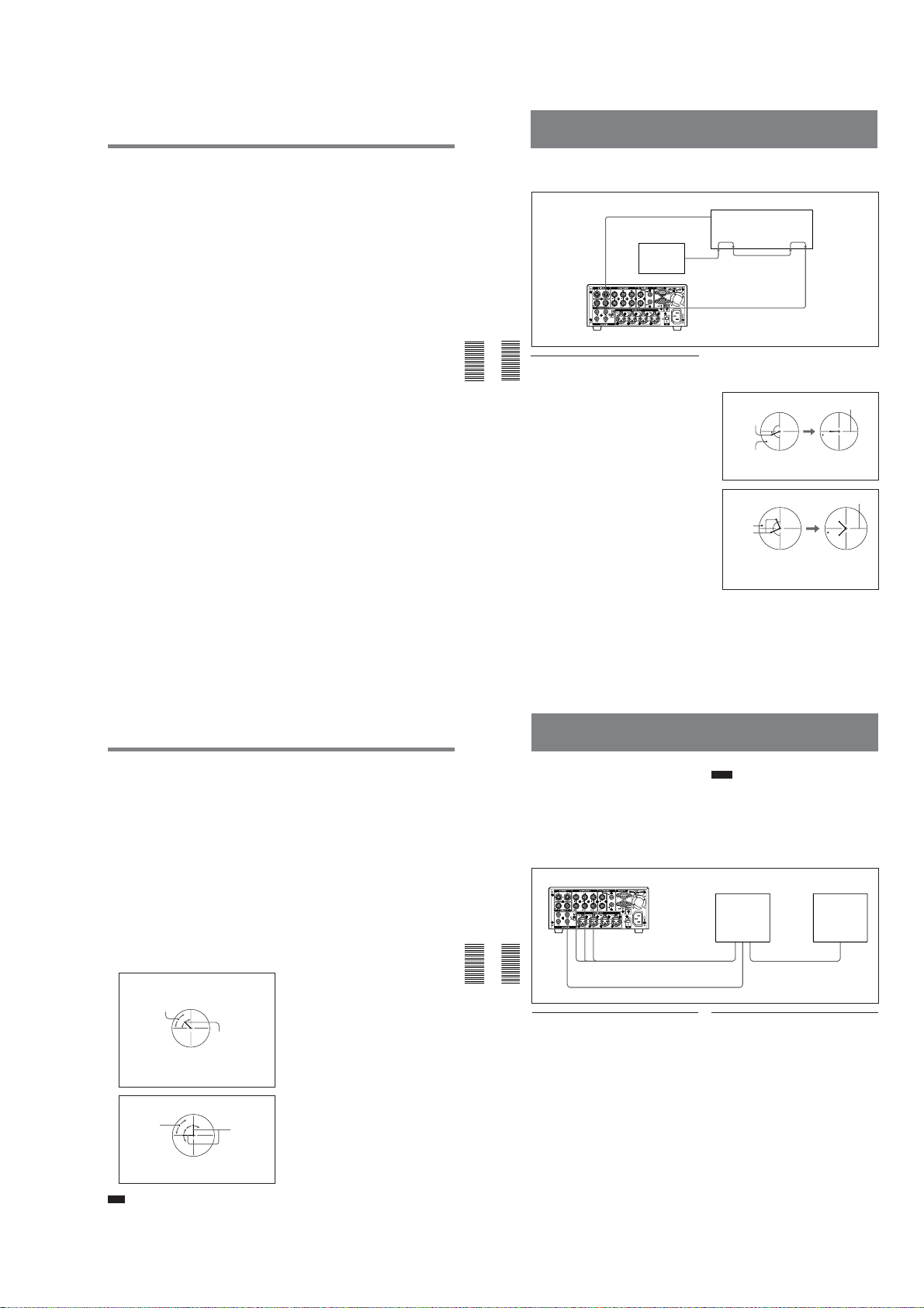
DSR-45/45P
A IN
B IN EXT. REF
Through
VIDEO OUT
VIDEO IN REF.IN
B Through EXT. REF
IN
VIDEO OUT
COMPONENT OUT
Adjusting the Sync and Subcarrier Phases of the
Video Signals
•If the external time code input is discontinuous or
does not advance correctly, the time code input may
be delayed compared to the time code recorded on the
tape or the time code shown on the display of this
unit. If there is a discontinuous time code on your
recorded tape, you may not be able to edit or search
correctly, depending on the device connected to this
unit.
When you adjust the phases of the video signals,
follow the steps below.
Performing a phase adjustment operation
1
Press the SCH button on the vectorscope.
Chapter 4 Setting the Time Code and Adjusting the Video Signals
Chapter 4 Setting the Time Code and Adjusting the Video Signals
The vectorscope goes into the “SCH” mode.
2
Press the B channel button on the vectorscope.
The black burst signal from the reference video
signal generator is selected.
3
Press the EXT button on the vectorscope.
The vectorscope goes into the external
synchronization mode.
Reference video
signal generator
DSR-45/45P
Vectorscope with SCH mode
Vectorscope with SCH mode
4
Adjust the phase synchronization control on the
vectorscope so that the sync and subcarrier phases
are close to the reference line.
(for NTSC)
Subcarrier
phase
Sync phase
Align the sync and subcarrier phase of the black burst
signal to the reference line.
(for PAL)
Sync
phase
Subcarrier
phase
Align the sync phase of the black burst signal to the
reference line.
Align the subcarrier phase of the black burst signal
symmetrically up and down.
Reference line
Reference line
5
Set EXT SYNC on the VIDEO SET menu to ON,
then play back a tape on this unit.
6
Press the A channel button on the vectorscope.
The vectorscope displays the sync phase and
subcarrier phase (composite signals only) of the
signal from this unit.
7
Adjust the SYNC control using H PHASE on the
VIDEO SET menu for rough adjustment, then
adjust H PHASE F for fine adjustment, so that the
output from this unit on channel (A) is in correct
phase alignment with the black burst signal on
channel (B).
8
Adjust the SC control using SC PHASE on the
VIDEO SET menu for rough adjustment, then
adjust SC PHASE F for fine adjustment, so that the
output from this unit on channel (A) is in correct
phase alignment with the black burst signal on
channel (B).
(for NTSC)
This indicator moves as you
adjust the H PHASE or H
PHASE F menu.
This indicator moves
as you adjust the SC
PHASE or SC
PHASE F menu.
Adjust the sync and subcarrier phase of the output
signal from this unit.
(for PAL)
This indicator
moves as you
adjust the H
PHASE or H
PHASE F menu.
Adjust the sync and subcarrier phase of the output
signal from this unit.
Note
When component signals are used, the subcarrier
phase indicator does not appear.
This indicator
moves as you
adjust the SC
PHASE or SC
PHASE F menu.
Chapter 4 Setting the Time Code and Adjusting the Video Signals65 (GB)
Chapter 4 Setting the Time Code and Adjusting the Video Signals67 (GB)
66
(GB) Chapter 4 Setting the Time Code and Adjusting the Video Signals
Adjusting the Signals
You can adjust each signal level of the component
output signal and the chrominance signal gain level of
the composite signal.
Connect the reference video (black burst) signal oneto-one with a device that generates the reference video
signal, or make a loop-through connection. If the
device has a terminal switch, terminate the connection
properly.
You need both a waveform monitor and a vectorscope
to display the component signals.
DSR-45/45P
Chapter 4 Setting the Time Code and Adjusting the Video Signals
Chapter 4 Setting the Time Code and Adjusting the Video Signals
Adjusting the component signal level
1
Play back a tape to output the signals from the Y,
R-Y and B-Y connectors of the COMPONENT
OUT connectors.
The waveform monitor displays the relevant
information.
2
Adjust the Y, R-Y, and B-Y signal levels in PB
LEVEL on the VIDEO SET menu.
Y LEVEL: Adjusts the Y signal level.
R-Y LEVEL: Adjusts the R-Y signal level.
B-Y LEVEL: Adjusts the B-Y signal level.
For details on “PB LEVEL,” see “VIDEO SET menu”
on page 86 (GB).
68
(GB) Chapter 4 Setting the Time Code and Adjusting the Video Signals
1-15
Notes
•You cannot adjust the Y level of the component
signal, that of the composite signal and that of the Svideo signal independently.
•The chrominance levels of the composite and S-video
signals are affected by the adjustment of the R-Y and
B-Y levels of the component signal.
•Adjust the output level while playing the tape.
•You cannot adjust the signals output from the DV
jack.
Composite
video input
Vectorscope
Waveform monitor
Component
input
Composite
video output
Composite
video input
Adjusting the chrominance signal gain
level of the composite signal
1
Play back a tape to output the signals from the
VIDEO OUT connector.
The vectorscope displays the relevant information.
2
Adjust the chrominance signal gain level in PB
LEVEL on the VIDEO SET menu.
For details on “PB LEVEL,” see “VIDEO SET menu”
on page 86 (GB).
DSR-45/45P
Duplication (generating a work tape with the same time code)
Chapter5
Duplication and
Audio Dubbing
Duplication (generating a work tape with the same time code)
If you copy a source tape using the DUP (duplicate)
button on this unit, you can copy the time codes
recorded on the source tape as they are. You can easily
make a work tape having the same time codes as the
source tape.
The duplicate function on this unit works only when
using a source tape recorded in DVCAM format and
with DV connections.
This unit functions as a recorder. To perform
duplication on this unit, make sure to change REC
MODE on the VTR SET menu to DVCAM first.
To set the duplicate mode
This unit has three duplicate modes.
Set DUPLICATE on the VTR SET menu to select a
duplicate mode as follows.
(AUTO TAPE COPY WITH
AUTOq
CASSETTE MEMORY COPY): The player and
the recorder automatically rewind the tape to the
beginning to start duplicating. The cassette
memory is also duplicated.
AUTOq (AUTO TAPE COPY): The player and
the recorder automatically rewind the tape to the
beginning to start duplicating. The cassette
memory is not duplicated.
MANUALq (MANUAL TAPE COPY): The tape
is duplicated from any location. The cassette
memory is not duplicated.
Duplicating a tape
The duplicate procedure differs depending on the
duplicate mode.
Notes
•If you operate the player while duplicating, the
duplicate process may be interrupted and the tape
may not be correctly duplicated. Do not operate the
player while duplicating.
•You can duplicate a tape regardless of the DISPLAY
SELECT selector setting, but the duplication screen
will be displayed only when the DISPLAY SELECT
selector has been set to DATA.
or AUTOq duplicate mode
AUTOq
1
Connect this unit and the player using an i.LINK
cable (DV cable, not supplied). After turning on
the power of this unit and the player, set the
INPUT SELECT selector on this unit to DV.
2
Press the STOP button on this unit to stop the tape
transport operation.
(Continued)
Chapter 5 Duplication and Audio Dubbing69 (GB)
3
While holding the DUP button down, press the
PLAY button on this unit.
This unit and the player will automatically rewind
the tape to the beginning. This unit enters the
duplicate-standby mode. The player enters the
playback pause mode. Then the DUP and PLAY
indicators on this unit light and the duplication
starts.
If you press the PAUSE and PLAY buttons
while holding the DUP button down in step 3
This unit and the player will automatically rewind the
tape to the beginning. This unit enters the duplicatestandby mode. The player enters the playback pause
mode. This unit does not start duplication until you
press the PAUSE button.
To stop duplication
Press the STOP button on this unit.
Notes
•You cannot pause during a duplicate process.
•Before you start duplication, make sure that the
player has finished loading the cassette.
•The duplication starts after the i.LINK
communication is established so that the first part of
the source tape is dropped on the copied tape.
•Set auto repeat to OFF when the player has an auto
repeat function and set auto rewind to ON when the
Chapter 5 Duplication and Audio Dubbing
player has an auto rewind function.
Chapter 5 Duplication and Audio Dubbing
•If the player has a still timer function, set the still
timer to the longest time possible to ensure enough
time for rewinding the tape to the beginning.
•If you have selected AUTOq
the cassette memory will be duplicated after the tape
has been duplicated. While the cassette memory is
being duplicated, an indicator showing the progress
of the duplication appears on the LCD monitor and
on the MONITOR VIDEO output. Duplicating the
cassette memory takes up to a few minutes depending
on the amount of data.
In the following cases, duplication of the cassette
memory will be cancelled and the duplicate operation
will be completed without duplicating the cassette
memory.
If, while the cassette memory is being duplicated;
– you press the STOP button.
– you turn off the power of this unit or of the player.
– you eject the cassette.
– you disconnect the DV cable.
70
(GB) Chapter 5 Duplication and Audio Dubbing
duplicate mode,
If the duplication of the cassette memory stops for
some reason, the cassette memory on the duplicated
tape will be completely erased.
•When both the recorder and the player are DSR-45/
45Ps, set the REMOTE/LOCAL switch of the player
as well as that of the recorder to LOCAL.
•If you operate the player while duplicating and the
PLAYER UNCONTROLLABLE warning message
appears and duplication is stopped, press the STOP
button on this unit, then repeat the procedure from
step 3.
•Normally, the player and recorder rewind their tapes
automatically after duplication. However, depending
on the specifications, some players do not.
MANUALq duplicate mode
1
Connect this unit and the player using an i.LINK
cable (DV cable, not supplied). After turning on
power of this unit and the player, set the INPUT
SELECT selector on this unit to DV.
2
Locate the points where you want to start playback
and recording.
3
Press the STOP button on this unit to stop the tape
transport operation.
4
While holding the DUP button down, press the
PLAY button on this unit.
This unit enters the duplicate-standby mode. The
player enters the playback pause mode. Then the
DUP and PLAY indicators on this unit light and
duplication starts.
To adjust the point where duplication starts
In step 4, while holding the DUP button down, press the
PAUSE button and the PLAY button. This unit will not
start duplication until you press the PAUSE button again.
After confirming that the PLAYER display has changed
to READY (flashing) on the LCD monitor, adjust the
duplication start point using the player, then press the
PAUSE button on this unit to start duplication.
To stop duplication
Press the STOP button on this unit.
Notes
•You cannot pause during a duplicate process.
•Before you start duplication, make sure that the
player has finished loading the cassette.
•The duplication starts after the i.LINK
communication is established so that the first part of
the source tape is dropped on the copied tape. Play
back the source tape from the preceding point.
•If the player has an auto repeat function, set the
function to off.
•You may not be able to duplicate the first part of the
source tape. Locate the recorded portion on the
source tape, then start duplicating.
•If there is a blank portion on the tape, the first part of
the recorded portion that follows may be dropped on
the copied tape.
•If you start duplication at some midpoint in the tape,
the search function may not work correctly on the
copied tape or problems may occur when editing. It is
recommended that you select AUTOq
AUTOq for the duplicate mode.
or
Detecting a blank portion during
duplication
If the unit detects a blank portion on the source tape
during duplication, the skip function will automatically
skip the blank portion, reducing the length of the
recorded part of the tape. (This function is available
only when the duplicate mode is AUTOq
AUTOq.)
The operations of the player and recorder (this unit)
when a blank portion is detected are as follows:
Detected status on
source tape
Detects a blank portion
10 seconds after detection
of a blank portion
Detects next recorded
portion
Returns to the location
immediately before the
blank portion ends
This unit performs the above operations automatically,
reducing the blank portion by 10 or more seconds in
duplicating a tape.
Notes
•If the duplicate mode has been set to MANUALq,
this unit will not skip a blank portion even if detects
one.
•Depending on the specifications, the skip function
may not work on some players.
•When this unit resumes duplication, the first part of
the recorded portion on the source tape may be
dropped on the copied tape.
•A recorded portion of less than one minute between
two blank portions may not be duplicated.
Player/Recorder (this unit)
operation
Player: Continues playing the
Recorder: Continues
Player: Continues playing the
Recorder: Stops.
Player: Rewinds the tape at
Recorder: Remains stopped.
Player: After entering the
Recorder: After entering the
or
tape.
recording.
tape another 10
seconds and searches
forward.
about –2 times normal
speed to the location
immediately before the
blank portion ends.
playback pause mode,
starts playing the tape.
recording pause
mode, starts
recording.
Duplication (generating a work tape with the same time code)
Warnings about duplication
If an error occurs during duplication, a STOP/
CAUTION number and warning message will be
displayed on the LCD monitor and the MONITOR
VIDEO output screen. Except for STOP/CAUTION
No. 60 (RECORDER: SHORTER TAPE), “Err” is
displayed on the display window.
STOP/
CAUTION
No.
00
01
02
03
10
11
12
13
14
Chapter 5 Duplication and Audio Dubbing
15
Chapter 5 Duplication and Audio Dubbing
16
18
a)
19
21
22
35
37
39
40
Warning Message
RECORDER:
[DV IN] NOT SELECTED
i.LINK CABLE:
DISCONNECTED
i.LINK CABLE:
MULTI CONNECTION
i.LINK CABLE:
BUS RESET
PLAYER:
RECORDING
PLAYER:
NO CASSETTE
PLAYER:
UNCONTROLLABLE
PLAYER:
UNCONTROLLABLE
PLAYER:
UNCONTROLLABLE
PLAYER:
NOT DVCAM
PLAYER:
UNCONTROLLABLE
PLAYER:
TAPE INFO. UNKNOWN
PLAYER:
CM ERROR
PLAYER:
EMERGENCY STOP
PLAYER:
DEW STOP
RECORDER:
DVCAM NOT SELECTED
RECORDER:
NO CM
RECORDER:
CM ERROR
RECORDER:
STOP
The following table lists these warnings and messages.
If a warning message is displayed, check this table and
take the appropriate action.
Cause/Remedy
The INPUT SELECT selector on the recorder (this unit) is not set to DV. t Set
the INPUT SELECT selector to DV.
The DV cable is not connected correctly. t Connect the DV cable correctly.
There are multiple DV connections or the DV connection is looped. t You
cannot connect multiple devices. Connect only one player to this unit.
The DV cable has been unplugged and plugged in again. t Check the DV cable
connection. Try to duplicate again.
The player is in the recording mode.
There is no cassette in the player.
The player cannot be controlled, or the duplicate mode has been set to
MANUALq and the source tape has reached the end of the tape.
The player rejects control.
The player is disabled or is in a different mode than the recorder (this unit) has
requested.
The source tape is not recorded in the DVCAM format. t You can only duplicate
a tape recorded in the DVCAM format.
The player has been manually operated or the player’s protection function
cancelled the playback pause mode when the duplicate mode was set to
or AUTOq.
AUTOq
The information on the cassette in the player cannot be read. t If the cassette
information is correct, clean the terminal on the cassette and insert the cassette
(see page 99 (GB))
again
The player could not read the cassette memory during duplication. t If the
cassette memory is correct, insert the cassette again.
The player has detected self-diagnostics. t Refer to the instruction manual of
the player.
Moisture condensation has occurred in the player. t Refer to the instruction
manual of the player.
REC MODE on the VTR SET menu of the recorder (this unit) is set to DV SP. t
Set REC MODE to DVCAM.
The cassette in the recorder (this unit) does not have cassette memory, but the
recorder tried to duplicate the cassette memory. t Insert a cassette with
cassette memory.
The cassette memory data cannot be written in the cassette in the recorder (this
unit). t Clean the terminals on the cassette
The recorder (this unit) stopped while duplicating.
.
(see page 99 (GB)).
Chapter 5 Duplication and Audio Dubbing71 (GB)
1-16
72
(GB) Chapter 5 Duplication and Audio Dubbing
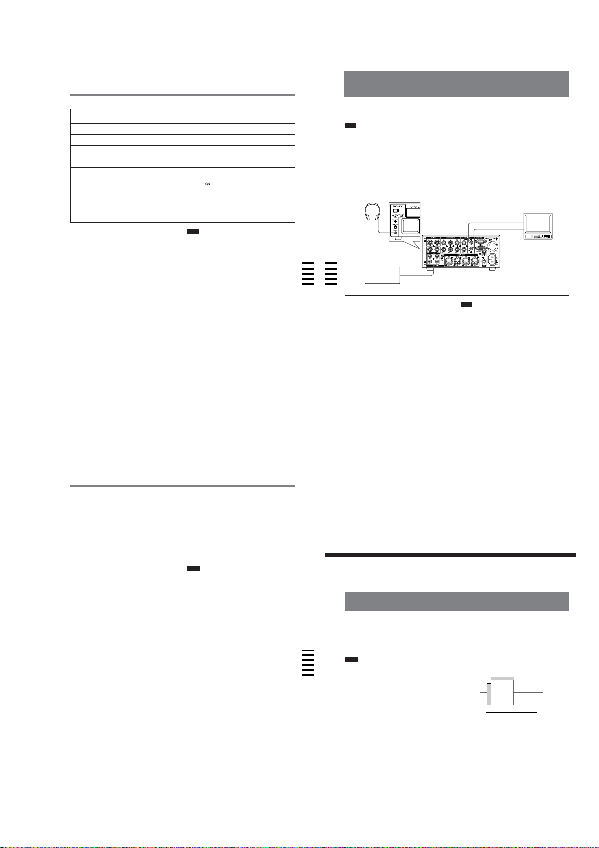
Audio Dubbing
1
CH1/2
MIN MAX
CH3/4
Audio Dubbing
DSR-45/45P
STOP/
Warning Message
CAUTION
No.
Z
41
%Z
42
RECORDER:
43
HEAD CLOG
PLAYER:
44
COPYRIGHT PROTECTED
RECORDER:
SMALLER CM SIZE
50
RECORDER:
b) c)
51
SHORTER TAPE
RECORDER:
SHORTER TAPE
b) c)
60
a) If the player could not read the cassette memory when
duplication started, this unit determines that the player’s
cassette does not have cassette memory and duplication
of the cassette memory will be cancelled. The duplicate
operation will be completed without duplicating the
cassette memory and this warning message will not be
displayed.
b) This unit detects tape length from the cassette memory
data. Even if two tapes with the same length in the
DVCAM format have been inserted in the player and the
recorder (this unit), complete duplication may not be
done due to the tape length error and this warning may
not be displayed. As a result, if you search the cassette
memory in the duplicated tape, the tape may not have a
search point even though the cassette memory has the
search point data.
c) If the cassette in the player does not have cassette
memory, this warning is not displayed.
Cause/Remedy
The recorder (this unit) detected self-diagnostics. t
diagnostics, see page 100 (GB).
Moisture condensation has occurred in the recorder (this unit). t If a cassette is
in the unit, remove the cassette and power on and wait more than one hour.
The recorder’s (this unit) video heads are clogged. t Clean the video heads with
the supplied cleaning cassette
A copyright protected signal is recorded on the cassette in the player. t You
cannot copy a copyright protected signal.
The cassette memory in the recorder (this unit) is smaller than the cassette
memory on the source tape. t Use a cassette that has larger cassette memory
than the one on the source tape. (This error is displayed only when the duplicate
mode has been set to AUTOq
The player’s cassette tape length is longer than that of the recorder’s (this unit)
cassette and duplication has failed. t Use a cassette with a tape length that is
longer than the one in the player.
The player’s cassette tape length is longer than that of the recorder’s (this unit)
cassette and there is a possibility that the duplication may fail. t Use a cassette
with a tape length that is longer than the one in the player. (This message is
displayed as a caution for 10 seconds after the start of duplication.)
For details on self-
(see page 98 (GB))
Note
If any warning message not listed in the table is
displayed, consult your Sony dealer.
.
.)
You can record just sound on a recorded tape.
(Audio dubbing)
Note
You can dub the sound onto a DVCAM-formatted
tape (recorded) in the 32 kHz audio mode (4-channel/
12 bits). You cannot dub the sound on a tape in the 48
kHz audio mode (2-channel/16 bits). If the audio mode
of the recorded tape is 32 kHz, you can dub the sound
regardless of the AUDIO MODE setting on the
AUDIO SET menu.
For details on “AUDIO MODE,” see “AUDIO SET menu”
on page 88 (GB).
Chapter 5 Duplication and Audio Dubbing
Chapter 5 Duplication and Audio Dubbing
Selecting the input channels for audio
dubbing
You can dub the sound in the following channel
combinations: channels 1/2 or channels 3/4.
Set AUDIO DUB on the AUDIO SET menu to select
the input channels for audio dubbing.
CH1,2: Selects the channel 1/2 combination.
CH3,4: Selects the channel 3/4 combination.
OFF: Disables audio dubbing.
Headphones
PHONES
Sound source
DSR-45/45P
(front panel)
Audio output
DSR-45/45P
(rear panel)
AUDIO IN
CH-1, CH-2 or
CH-3, CH-4
Connection of external devices
The following shows an example of a basic connection
for audio dubbing.
MONITOR AUDIO
Video input
Audio input
Monitor
MONITOR VIDEO
Note
You cannot dub sound in the following channel
combinations:
•Channels 1 to 4 simultaneously
•Only one channel
•Three channels simultaneously (excluding one
channel)
•Channel 1/3, channel 2/4, channel 1/4 and channel
2/3 combinations
Dubbing sound
1
Connect the unit and the sound source using a
phono jack cable (not supplied).
2
Set the INPUT SELECT selector to a setting other
than DV.
3
Switch the INPUT LEVEL selector to select the
audio input signal level (–10, –2 or +4).
4
Play back the tape inserted in this unit.
5
At the point you want to start dubbing, press the
PAUSE button to turn the unit to the playback
pause mode.
6
While holding the AUDIO DUB button down,
press the PLAY button to turn the unit to the audio
dubbing pause mode.
The AUDIO DUB indicator on this unit lights.
7
Set the AUDIO INPUT switch to AUTO or
MANU.
8
Adjust the recording level by turning the AUDIO
REC LEVEL control knobs.
You can adjust the recording level with the
AUDIO REC LEVEL control knobs if you have
selected MANU in step 7. While looking at the
audio level meters on the LCD monitor, turn the
AUDIO REC LEVEL control knobs and adjust the
recording level. Adjust the audio recording level so
that the recording level does not exceed 0 dB when
the audio signal is at its maximum. If the recording
level exceeds 0 dB, the sound will be distorted.
9
Press the PAUSE button.
The PAUSE indicator goes off and audio dubbing
starts.
To pause audio dubbing
Press the PAUSE button.
Pressing the PAUSE button again resumes audio
dubbing.
Chapter 5 Duplication and Audio Dubbing73 (GB)
To stop audio dubbing
Press the STOP button.
To monitor the sound you want
Set the AUDIO MONITOR selector as follows:
CH-1/2: You can listen to sound on channels 1/2 on
the tape or the sound to be dubbed.
CH-3/4: You can listen to sound on channels 3/4 on
the tape or the sound to be dubbed.
MIX: You can listen to the sound on the tape and the
dubbed sound.
Notes
•You can monitor the sound on the tape while dubbing
the sound. However, there are some delays between
the sound being recorded and the sound being played.
When you play back the tape after audio dubbing,
you might hear the dubbed sound later than the sound
monitored during audio dubbing.
•You cannot dub sounds onto a blank portion of the
tape.
74
(GB) Chapter 5 Duplication and Audio Dubbing
Operating the Menus
Operating the Menus
The unit allows you to set various parameters in the
menus. Before you start using the unit, set the internal
clock in CLOCK SET on the OTHERS menu. Except
for clock setting, you can use all other factory-set
default parameters but change them as needed.
Notes
•If the internal backup battery is exhausted, the time
set in the internal clock and the time code of the
Chapter 5 Duplication and Audio Dubbing
FREE RUN setting will be initialized. The internal
backup battery is fully charged if you connect the
power to the unit for about 8 hours. A fully charged
internal battery can run for about two weeks.
•Do not pull out the plug of the power cord from an
AC outlet or the unit while adjusting the menu or the
brightness of the LCD monitor. Otherwise, the
Chapter 6 Adjusting and Setting Through Menus
settings of the menu may be changed accidentally.
Chapter
6
Adjusting and Setting
Through Menus
Displaying the menu
1
Set the CHARACTER DISPLAY (LCD) selector
to ON or ON (BLACK BACK).
2
Set the DISPLAY SELECT selector to MENU.
The menu is superimposed on the LCD monitor.
TC ⁄ UB SET
TC
TC PRESET
RMT
UB PRESET
CM
TC ⁄ UB IN
DISP
DV IN TC
Icons Submenus
V
TC MAKE
A
TC RUN
VTR
TC FORMAT
ETC
JOG TC OUT
76
Chapter 5 Duplication and Audio Dubbing75 (GB)
1-17
(GB) Chapter 6 Adjusting and Setting Through Menus
DSR-45/45P
Operating the Menus
Changing the menu settings
1
Pressing the J/j buttons, select the menu icon
you want to change, then press the EXEC button.
2
Pressing the J/j buttons, select the submenu you
want to change, then press the EXEC button.
3
Pressing the J/j buttons, change the setting.
4
Press the EXEC button to return to the submenu.
5
Repeat steps 1 to 4, as needed.
To return to step 1
Press the J/j buttons to select
press the EXEC button.
RETURN, then
Menu Organization
The menu of this unit consists of the following menus
and submenus.
TC/UB SET TC PRESET
REMOTE LOCAL ENBL
CM SET CM SEARCH
DISPLAY SET DATA CODE
VIDEO SET PB YNR
AUDIO SET AUDIO MODE
VTR SET REC MODE
OTHERS COMMANDER
a) DSR-45 only
b) COLOUR BAR for DSR-45P
c) LCD COLOUR for DSR-45P
Chapter 6 Adjusting and Setting Through Menus77 (GB)
UB PRESET
TC/UB IN
DV IN TC
TC MAKE
TC RUN
(page 79 (GB))
TC FORMAT
JOG TC OUT
PREROLL
POST CUEUP
STILL DLY
232C RATE
TITLE DISP
LABEL DISP
TAPE LABEL
ITEM ERASE
ERASE ALL
EE/PB SEL
LTR SIZE
COLOR BAR
DATE DISP
TIME DISP
(page 86 (GB))
PB CNR
(page 86 (GB))
PB LEVEL
EXT SYNC
H PHASE
H PHASE F
SC PHASE
SC PHASE F
AUDIO DUB
JOG AUDIO
REF LEVEL
AGC CH1,2
AGC CH3,4
LIMITER
(page 89 (GB))
AUTO INDEX
STILL PICT
FF/REW SPD
DUPLICATE
DV EE OUT
STILL TIME
FROM STILL
AC ON MODE
AUTO STBY
BEEP
(page 92 (GB))
LCD BRIGHT
LCD COLOR
CLOCK SET
HRS METER
(page 78 (GB))
(page 78 (GB))
(page 78 (GB))
(page 79 (GB))
(page 79 (GB))
(page 79 (GB))
(page 80 (GB))
(page 80 (GB))
(page 80 (GB))
(page 80 (GB))
(page 80 (GB))
(page 80 (GB))
(page 81 (GB))
(page 81 (GB))
(page 81 (GB))
(page 82 (GB))
(page 83 (GB))
(page 84 (GB))
(page 85 (GB))
(page 85 (GB))
(page 85 (GB))
(page 85 (GB))
(page 86 (GB))
(page 86 (GB))
(page 87 (GB))
(page 87 (GB))
(page 87 (GB))
(page 87 (GB))
(page 88 (GB))
(page 88 (GB))
(page 88 (GB))
(page 88 (GB))
(page 88 (GB))
(page 89 (GB))
(page 89 (GB))
(page 89 (GB))
(page 90 (GB))
(page 90 (GB))
(page 90 (GB))
(page 90 (GB))
(page 91 (GB))
(page 91 (GB))
(page 91 (GB))
(page 91 (GB))
(page 92 (GB))
(page 92 (GB))
(page 92 (GB))
(page 92 (GB))
(page 92 (GB))
(page 92 (GB))
(page 92 (GB))
Menu Contents
Initial settings are indicated with rectangles.
a)
b)
Chapter 6 Adjusting and Setting Through Menus
c)
TC/UB SET menu
Note
All items other than JOG TC OUT can be set only
when you record in DVCAM format.
Icon/Menu
TC
Chapter 6 Adjusting and Setting Through Menus
78
Submenu
Setting
(page)
TC/UB SET
Resets/Sets the time code value.
TC PRESET
(page 58 (GB))
RESET: Resets the time code value to 00:00:00:00.
PRESET: Sets the time code value.
RETURN : Returns to the TC/UB SET menu without changing the time code value.
Note
To set the initial time code value, you need to set TC MAKE to PRESET first. If TC MAKE
has been set to REGEN, you cannot change the time code using this item.
UB PRESET
Resets/Sets the user bits value.
(page 59 (GB))
RESET: Resets the user bits value to 00 00 00 00.
PRESET: Sets the user bits value. (You can set the user bits as eight-digit hexadecimal
RETURN : Returns to the TC/UB SET menu without changing the user bits value.
Selects the time code and user bits to record on the tape.
TC/UB IN
INTERNAL : Uses the internal time code/user bits.
(page 60 (GB))
TC&UB EXT: Uses external time code/user bits.
TC EXT: Uses an external time code and internal user bits.
UB EXT: Uses the internal time code and external user bits.
Notes
• The time code output from this unit has some restrictions. For details, see pages 64 (GB),
65 (GB).
• Press the EXEC button to change the setting of this item. This will also be carried out the
moment you switch the position of the DISPLAY SELECT selector to DATA or AUDIO.
(GB) Chapter 6 Adjusting and Setting Through Menus
values (0 to 9, A to F) (base 16) to have the date, time, scene number, and other
information inserted into the user bits.)
Icon/Menu
TC
TC/UB SET
Submenu
Setting
(page)
DV IN TC
Selects whether to record internal time code or external time code while the unit records the
(page 60 (GB))
signals input via the DV jack in DVCAM format.
INTERNAL : Records the time code generated by the internal time code generator. (The
value of the time code or user bits depends on the settings of other menu items, such as
TC PRESET, UB PRESET, or TC MAKE.)
EXTERNAL: Records the time code with video and audio signals input via the DV jack.
Notes
• When you set REC MODE on the VTR SET menu to DV SP, this item cannot be used.
Even if this item is set to EXTERNAL, when you set REC MODE on the VTR SET menu to
DV SP, the setting becomes invalid and the unit records the internal time code.
• When this item is set to EXTERNAL, the INPUT SELECT selector on the front panel is set
to DV, and no signal is input via the DV jack, or the software of the editing controller does
not output a time code, if you start recording, bars (– –:– –:– –:– –) are recorded as time
code. At the point that the input of a signal begins, the time code of that signal will be
recorded.
• When this item is set to EXTERNAL, if you input time code to the DV jack that is not
continuous or does not advance correctly, the value of the recorded or displayed time
code may not be equal to the actual value of the input one. If you use a tape with this
problem, you may not be able to perform search or edit, depending on the devices you
TC MAKE
(page 61 (GB))
TC RUN
(page 61 (GB))
TC FORMAT
(page 61 (GB))
use.
Selects the time code when you start recording.
REGEN : The time code value is set to continuous time code from the one already
recorded on the tape. If no time code is recorded on the tape, it starts from 00:00:00:00.
PRESET: The time code starts from the value set in TC PRESET on the TC/UB SET
menu.
Selects the advancement mode (counting up).
REC RUN : Time code value advances only while recording.
FREE RUN: Time code value advances even when the unit is not recording. (This mode is
used to set the current time as the initial time code value, or to synchronize the internal
time code to an external time code.)
Notes
• If you set the advancement mode to FREE RUN, the time code will be updated by the
internal clock when the power is off. Therefore, when you turn on the unit again, the time
code may have been delayed or advanced somewhat.
• If the internal backup battery is exhausted, the time code of the FREE RUN setting is
initialized.
Selects the frame mode.
AUTO : Automatically sets the frame mode in accordance with the inserted cassette. (If
nothing is recorded on the tape, the mode is set to the non-drop frame mode. If the unit
cannot read the frame mode correctly in the tape, the unit will use the frame mode that
was set in the last position it was able to read correctly on the tape. If you remove the
cassette, the mode of the last position it was able to read correctly is cleared and the
mode is set to the non-drop frame mode. If TC MAKE is set to PRESET, the mode is
also set to the non-drop frame mode.)
DF: Selects the drop frame mode.
NDF: Selects the non-drop frame mode.
Notes
• This menu is displayed only for the DSR-45.
• Regardless of this item setting, the frame mode is set to drop frame when you record in
DV format.
Operating the Menus
Icon/Menu
TC
TC/UB SET
REMOTE menu
Icon/Menu
RMT
REMOTE
Chapter 6 Adjusting and Setting Through Menus
Chapter 6 Adjusting and Setting Through Menus
Submenu
Setting
(page)
JOG TC OUT
Controls the time code output from the TC OUT connector when the tape is played at a
speed other than normal.
(page 61 (GB))
OFF : Does not output the time code.
ON: Outputs the time code.
Note
Continuous time code is output only when the tape is played at a normal speed. When the
unit is in the search mode, discontinuous time code is output.
Submenu
Setting
(page)
Restricts the functions of the buttons on the front panel, the Remote Commander, and the
LOCAL ENBL
(page 12 (GB))
Remote Control Unit (not supplied) connected to the CONTROL S IN jack, when the
REMOTE/LOCAL switch is set to REMOTE.
NO KEY : Disables all buttons on the devices described above.
EJECT: Disables all buttons except EJECT on the devices described above.
STOP&EJECT: Disables all buttons except EJECT and STOP on the devices described
above.
ALL KEYS: Enables all buttons on the devices described above.
Notes
• Even if the REMOTE/LOCAL switch is set to REMOTE, the Remote Commander functions
depend on the setting of this item. If you want to disable the Remote Commander, set
COMMANDER on the OTHERS menu to CONTROL S.
• Press the EXEC button to change the setting of this item. This will also be carried out the
moment you switch the position of the DISPLAY SELECT selector to DATA or AUDIO.
• While the REMOTE/LOCAL switch is set to REMOTE, if you change this item from ALL
KEYS to any other setting, the setting is activated at that instant and the J, j, and EXEC
buttons, which are used to adjust the menus, are disabled. To enable those buttons again,
set the REMOTE/LOCAL switch to LOCAL.
PREROLL Sets the duration of the preroll time. (only for an RS-422A connection)
3 SEC: Three seconds
5 SEC: Five seconds
7 SEC : Seven seconds
10 SEC: 10 seconds
Notes
• Depending on the types of editing controller used, the unit may take the preroll time set by
the editing controller, ignoring setting of this item.
• On the editing controller, set the preroll time to five seconds or longer.
POST
Selects the information which the unit sends to an editing controller to let it know the state
CUEUP
of the unit when the tape reaches a searched for point. (only for an RS-422A connection)
STOP : Informs the editing controller that the unit is in the stop mode.
STILL: Informs the editing controller that the unit is in the playback pause mode.
STILL DLY
Playback still delay can be set between 0 and 10 frames by 11 steps. You can set the delay
which the unit turns to playback mode from still mode. (only for an RS-422A connection)
Note
The default is 0 frame.
Chapter 6 Adjusting and Setting Through Menus79 (GB)
1-18
80
(GB) Chapter 6 Adjusting and Setting Through Menus
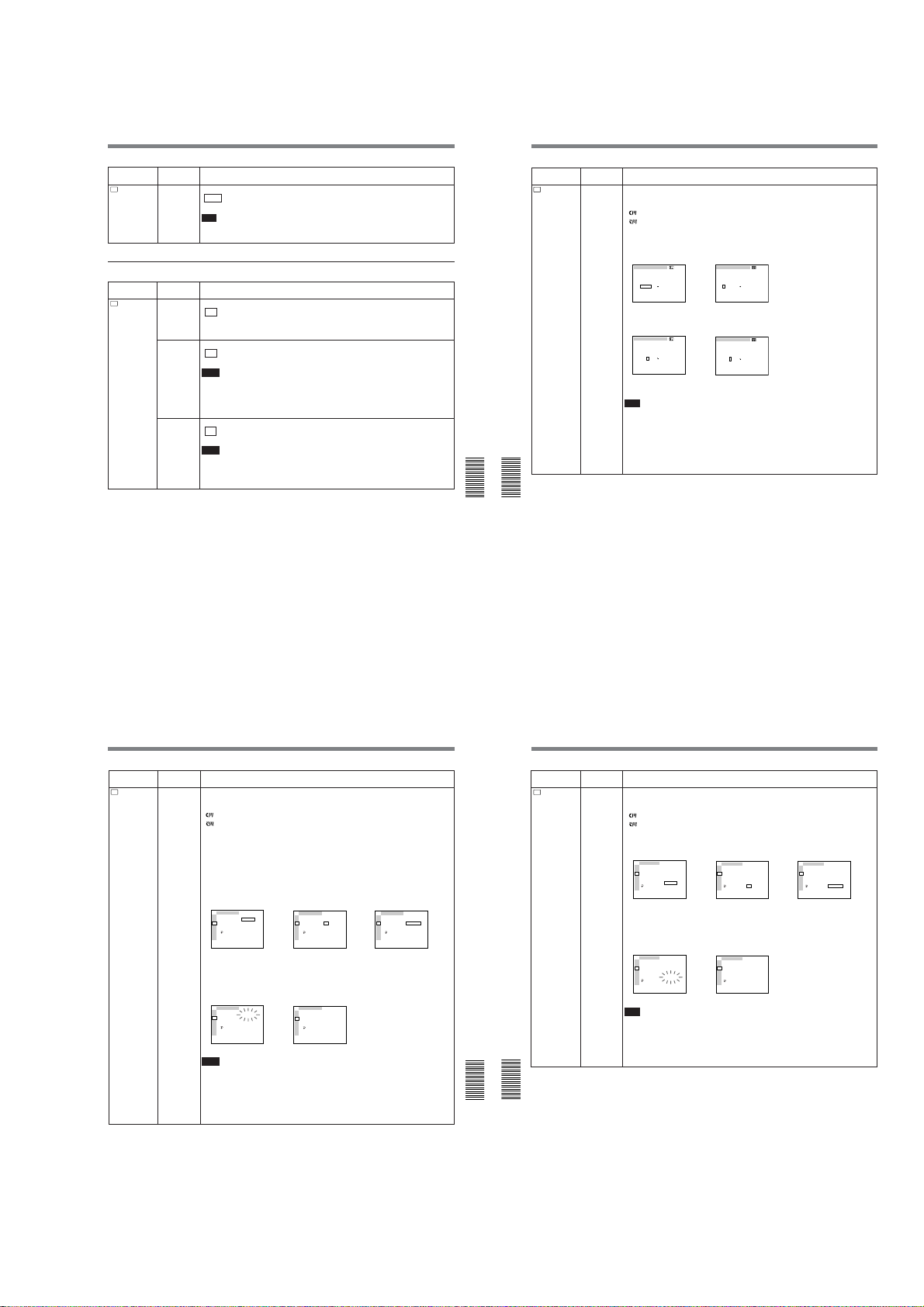
Operating the Menus
CM SET
CM SEARCH
TITLE DISP
LABEL DISP
TAPE LABEL
ITEM ERASE
ERASE ALL
RETURN
RETURN
OK
TC
RMT
CM
DISP
V
A
VTR
ETC
CM SET
CM SEARCH
TITLE DISP
LABEL DISP
TAPE LABEL
ITEM ERASE
ERASE ALL
RETURN
ERASING
TC
RMT
CM
DISP
V
A
VTR
ETC
DSR-45/45P
Icon/Menu
RMT
REMOTE
CM SET menu
Icon/Menu
CM
CM SET
Submenu
Setting
(page)
232C RATE Selects the baud rate via the RS-232C connector.
9600 : 9600 bps
19200: 19200 bps
Note
For editing, if you intend to use this unit as a player and the FXE-120/120P or FXE-100/
100P as an editing controller, set the baud rate of both devices to 19200 bps.
Submenu
Setting
(page)
CM SEARCH Selects the mode used to search scenes.
LABEL DISP
ON : Searches scenes using the cassette memory. (If the cassette does not have
cassette memory, the search for the scenes can be done using the search signals on
the tape.)
OFF: Always searches scenes using the search signals on the tape.
TITLE DISP Selects whether or not to display the title.
ON : Displays the title.
OFF: Hides the title.
Notes
• The title input with the camera or external device is displayed. You cannot enter a title
using this unit.
• The unit cannot display a font that the unit does not have.
• The title is displayed only on the LCD monitor or MONITOR VIDEO output.
• The title is only displayed if you have set the DISPLAY SELECT selector to DATA.
Selects whether or not to display the tape label.
ON : Displays the tape label.
OFF: Hides the tape label.
Notes
• The tape label is displayed only on the LCD monitor or MONITOR VIDEO output.
• The tape label is only displayed if you have set the DISPLAY SELECT selector to DATA.
• If the tape label has been made with another VCR or camcorder, this unit cannot display a
tape label that includes a font that the unit does not have.
Icon/Menu
CM
CM SET
Chapter 6 Adjusting and Setting Through Menus
Chapter 6 Adjusting and Setting Through Menus
Submenu
Setting
(page)
TAPE LABEL Makes a tape label. (You can enter up to 10 characters on a tape label.)
If you select this item, one of the following symbols appears. If no cassette is loaded,
nothing is displayed.
: Cassette with cassette memory
: Cassette without cassette memory
You can make a tape label as follows:
1 On the TAPE LABEL screen, select a line that has the alphabet character you want by
pressing the J/j buttons and the EXEC button. (The cursor moves to the first character
of the line.)
TAPE LABEL
__________
A
D
1
B
E
C
2
3
4
5
F
I
6
G
J
H
7
8
9
0
M
O
K
N
'
L
.
,
/
–
Q
R
T
P
S
[
]
V
W
Y
U
X
[
S
E
T
]
!
Z
?
&
2 Select a character by pressing the J/j buttons and the EXEC button. (The selected
character is entered. To erase a character, select [ P ]; the last character is erased.)
TAPE LABEL
__________
A
D
1
B
E
2
C
3
4
5
F
I
6
G
J
7
H
8
9
0
M
O
K
N
'
L
.
,
/
–
Q
R
T
P
S
[
]
Y
V
W
U
X
[
S
E
T
]
!
Z
?
&
3 Repeat steps 1 and 2. After entering all characters for the tape label, select [SET].
Note
The unit cannot display the TAPE LABEL screen in the following cases:
• The unit does not have a cassette inserted or the tape is being unloaded.
• The cassette does not have cassette memory.
• The cassette memory is full of data other than the tape label data.
• The cassette is write-protected.
• The tape is being recorded.
• The tape is being duplicated.
• The cassette memory is being used.
TAPE LABEL
__________
A
D
1
B
E
C
2
3
4
5
F
I
6
G
J
H
7
8
9
0
M
O
K
N
'
L
.
,
/
Q
R
P
V
W
U
Z
&
TAPE LABEL
S_________
A
B
C
F
G
H
M
K
L
Q
R
P
V
W
U
Z
&
–
T
S
[
]
Y
X
[
S
E
T
]
!
?
D
1
E
2
3
4
5
I
6
J
7
8
9
0
O
N
'
.
,
/
–
T
S
[
]
Y
X
[
S
E
T
]
!
?
,
,
Icon/Menu
CM
CM SET
Chapter 6 Adjusting and Setting Through Menus81 (GB)
Submenu
Setting
(page)
Erase a cassette memory item.
ITEM ERASE
If you select this item, one of the following symbols appears. If no cassette is loaded,
nothing is displayed.
: Cassette with cassette memory
: Cassette without cassette memory
The available items are as follows:
INDEX ALL: Erases the index data.
TITLE ALL: Erases the title data.
DATE ALL: Erases the date data.
PHOTO ALL: Erases the photo data.
You can erase an item as follows:
1 Select an item to erase by pressing the J/j buttons and the EXEC button.
2 To erase the item, select OK, otherwise select RETURN. (If you select OK, the unit will
check again to see if you really want to erase the item.)
CM SET
TC
ITEM ERASE
RMT
INDEX ALL
RETURN
CM
TITLE ALL
OK
DISP
DATE ALL
V
PHOTO ALL
A
RETURN
VTR
ETC
3 To erase the item, select EXECUTE, otherwise select RETURN. (If you select
EXECUTE, the ERASING message will flash, and the unit will start erasing the item in
the cassette memory. While the ERASING message is flashing, you cannot use the J/j
buttons or the EXEC button. After the item has been erased, the COMPLETE message
appears. Press the J/j buttons or the EXEC button to erase the COMPLETE message.)
CM SET
TC
ITEM ERASE
RMT
INDEX ALL
ERASING
CM
TITLE ALL
DISP
DATE ALL
V
PHOTO ALL
A
RETURN
VTR
ETC
Notes
• You cannot make a title, mark the date for date search, or record in the photo mode.
• You cannot erase an item in the cassette memory in the following cases:
– The unit does not have a cassette inserted or the tape is being unloaded.
– The cassette does not have cassette memory.
– The cassette is write-protected.
– The tape is being recorded.
– The tape is being duplicated.
CM SET
TC
ITEM ERASE
RMT
INDEX ALL
RETURN
CM
TITLE ALL
OK
DISP
DATE ALL
V
PHOTO ALL
,
A
RETURN
VTR
ETC
CM SET
TC
ITEM ERASE
RMT
INDEX ALL
COMPLETE
CM
TITLE ALL
DISP
DATE ALL
V
PHOTO ALL
,
A
RETURN
VTR
ETC
82
(GB) Chapter 6 Adjusting and Setting Through Menus
Operating the Menus
CM SET
Submenu
Setting
(page)
ERASE ALL
Erases all the items in the cassette memory.
If you select this item, one of the following symbols appears. If no cassette is loaded,
nothing is displayed.
: Tape with cassette memory
: Tape without cassette memory
Erase all items in the cassette memory as follows:
1 To erase all items, select OK, otherwise select RETURN. (If you select OK, the unit will
check again to see if you really want to erase all items.)
2 To erase all items, select EXECUTE, otherwise select RETURN. (If you select
EXECUTE, the ERASING message will flash, and the unit starts erasing all items in the
cassette memory. While the ERASING message is flashing, you cannot use the J/j
buttons or the EXEC button. After all items have been erased, the COMPLETE message
appears. Press the J/j buttons or the EXEC button to erase the COMPLETE message.)
Note
You cannot erase all the items in the cassette memory in the following cases:
• The unit does not have a cassette inserted or the tape is being unloaded.
• The cassette does not have cassette memory.
• The cassette is write-protected.
• The tape is being recorded.
• The tape is being duplicated.
CM SET
TC
CM SEARCH
RMT
TITLE DISP
CM
LABEL DISP
DISP
TAPE LABEL
V
ITEM ERASE
,
A
RETURN
ERASE ALL
VTR
OK
RETURN
ETC
CM SET
TC
CM SEARCH
RMT
TITLE DISP
CM
LABEL DISP
DISP
TAPE LABEL
V
ITEM ERASE
,
A
COMPLETE
ERASE ALL
VTR
RETURN
ETC
CM SET
TC
CM SEARCH
RMT
TITLE DISP
CM
LABEL DISP
DISP
TAPE LABEL
V
ITEM ERASE
,
A
RETURN
ERASE ALL
VTR
EXECUTE
RETURN
ETC
Icon/Menu
CM
CM SET
TC
ITEM ERASE
RMT
INDEX ALL
RETURN
CM
TITLE ALL
EXECUTE
DISP
DATE ALL
V
PHOTO ALL
,
A
RETURN
VTR
ETC
Chapter 6 Adjusting and Setting Through Menus
Chapter 6 Adjusting and Setting Through Menus
Chapter 6 Adjusting and Setting Through Menus83 (GB)
1-19
84
(GB) Chapter 6 Adjusting and Setting Through Menus
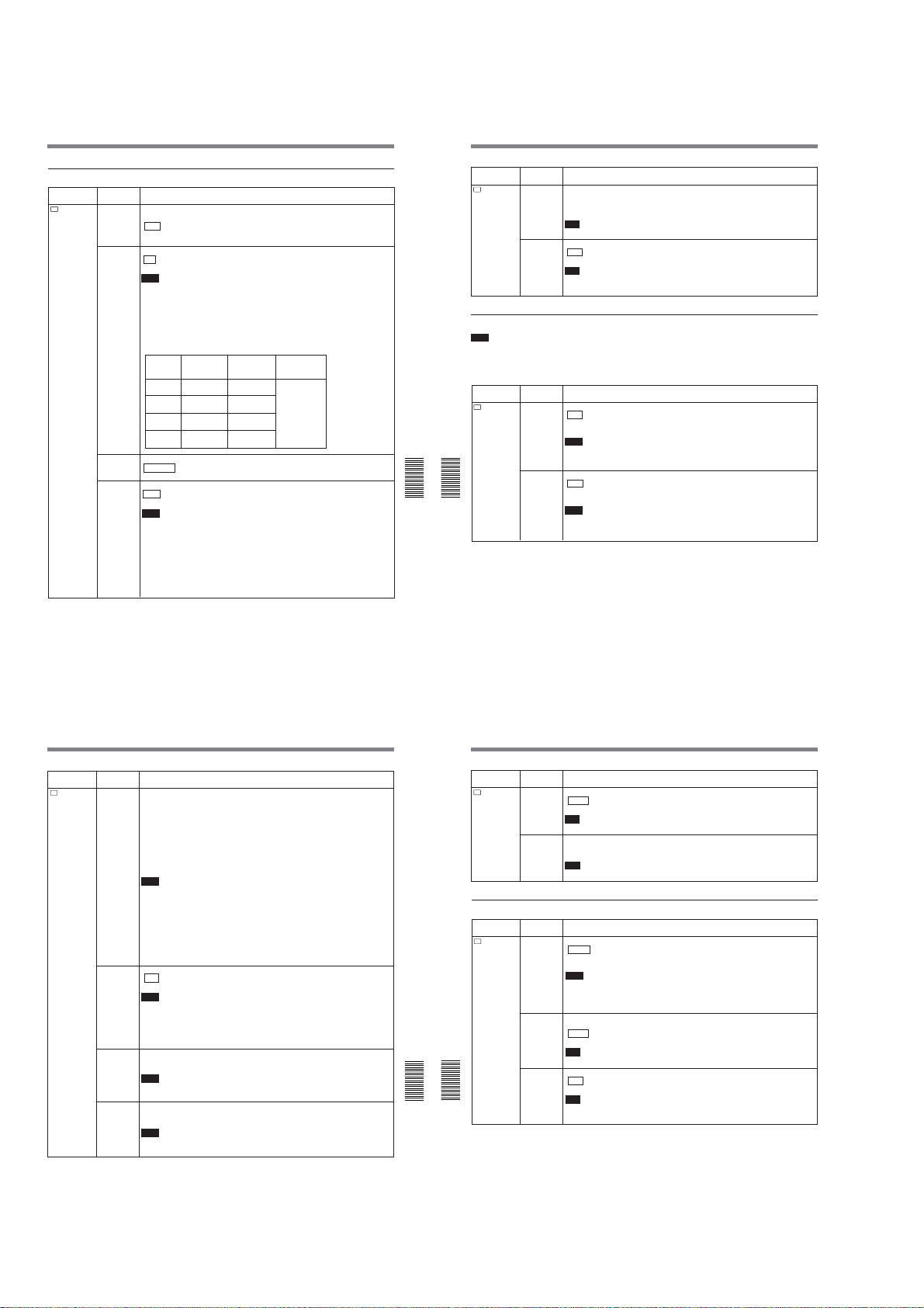
DSR-45/45P
Operating the Menus
DISPLAY SET menu
DISPLAY
Submenu
(page)
DATA CODE
(page 36 (GB))
EE/PB SEL
(page 17 (GB))
LTR SIZE
COLOR BAR
(for DSR-45) /
COLOUR BAR
(for DSR-45P)
Icon/Menu
DISP
SET
Setting
Selects whether or not to display the data codes on the LCD monitor and the MONITOR
VIDEO output.
OFF : Does not display the data codes.
DATE: Displays the date when recorded.
CAMERA: Displays the camera data.
Sets the stop, fast-forward and rewind modes.
EE : Outputs EE pictures (sound, time code).
PB: Mutes the image and sound.
Notes
• Even if EXT SYNC on the VIDEO SET menu is set to ON, the line-outs (VIDEO OUT,
COMPONENT OUT, S VIDEO OUT) in the EE mode are delayed from those of the input
signals as follows:
– delayed for two lines when signals are input via the VIDEO IN REF.IN connector.
– delayed for one line when signals are input via the S VIDEO IN or COMPONENT IN
connector.
• If this item is set to PB, the output from the unit will be as follows when you press any of
the REC, DUP, or AUDIO DUB buttons separately when the unit is stopped (unless the
cassette has been write-protected).
Image
Sound
Time code
EE picture of
REC button
the input image
DUP button Image input to
the DV jack
AUDIO
Mute screen
DUB button
(black)
Mute screen
No button
(black)
is pressed
Changes the font size of the menu line at the cursor.
NORMAL : Normal size
2×: Double height size
Displays/hides the color bars.
OFF : Does not display the color bars.
ON: Displays the color bars.
Notes
• You cannot display the color bars while the unit is playing the tape or when the INPUT
SELECT selector is set to DV.
• The color bars are displayed only on the LCD monitor or MONITOR VIDEO output.
• If you record when the color bars are displayed, the color bars will also be recorded on the
tape.
• You cannot adjust the MONITOR VIDEO output. Do not use the color bars output from the
MONITOR VIDEO jack as a reference signal.
• The reference sound signals are not output even if this item is set to ON.
• This item will be automatically set to OFF if you set the INPUT SELECT selector to DV or
you operate the unit to play back a tape.
EE sound of the
input sound
Sound input to
the DV jack
EE sound of the
input sound
Mute
(no sound)
(See page 63 (GB))
Icon/Menu
DISP
DISPLAY
SET
VIDEO SET menu
Note
To perform the adjustment in H PHASE, H PHASE F,
SC PHASE, or SC PHASE F, you must set EXT
SYNC to ON and input the reference video signals to
the VIDEO IN REF.IN connector.
Icon/Menu
V
VIDEO SET PB YNR Switches the noise reduction level for the luminance signals when a tape is played.
Chapter 6 Adjusting and Setting Through Menus
Chapter 6 Adjusting and Setting Through Menus
Submenu
Setting
(page)
DATE DISP Selects the form of the date displayed on the search screen or of the data codes and so on.
Y/M/D: Displays YY/MM/DD (year/month/day).
M/D/Y: Displays MM/DD/YY (month/day/year).
D/M/Y: Displays DD/MM/YY (day/month/year).
Note
The default is M/D/Y for the DSR-45; and D/M/Y for the DSR-45P.
TIME DISP
Selects the form of the time displayed on the search screen or of the data codes and so on.
24H : Displays 24-hour time.
12H: Displays 12-hour time.
Note
The counter of this unit operates only on a 12-hour cycle. Even if you set this item to 24H,
the counter value is displayed on a 12-hour cycle.
Submenu
Setting
(page)
OFF : No noise reduction
LOW: Low noise reduction
HIGH: High noise reduction
Notes
• When you use noise reduction, there may be an afterimage depending on the condition of
the picture.
• The setting of this item does not affect a signal output via the DV jack.
PB CNR
Switches the noise reduction level for the chrominance signals when a tape is played.
OFF : No noise reduction
LOW: Low noise reduction
HIGH: High noise reduction
Notes
• When you use noise reduction, there may be an afterimage depending on the condition of
the picture.
• The setting of this item does not affect a signal output via the DV jack.
Icon/Menu
V
VIDEO SET
Chapter 6 Adjusting and Setting Through Menus85 (GB)
Submenu
Setting
(page)
PB LEVEL
Adjusts the output video signal levels. (This is available only when the mode is playback,
(page 68 (GB))
playback pause, slow playback, cue, or review.)
SETUP: Switches the luminance signal setup level (0% or 7.5%). (This item is only for the
DSR-45. The setup level for the DSR-45P is fixed to 0%.)
Y LEVEL: Adjusts the Y signal level of the component signals. (If you change this, the Y
signal level of the composite video and S VIDEO will also be changed.)
R-Y LEVEL: Adjusts the R-Y signal level of the component signals. (If you change this,
the chrominance level of the composite video and S VIDEO will also be changed.)
B-Y LEVEL: Adjusts the B-Y signal level of the component signals. (If you change this,
the chrominance level of the composite video and S VIDEO will also be changed.)
CHROMA: Adjusts the chrominance level in the composite signals.
Notes
• You can adjust the video levels only while playing the tape.
• Adjust the video levels by looking at the bars (except SETUP). (The triangles under the
bars are displayed in green when the settings are set to the factory preset values.)
• The SETUP default is 0%. Other defaults are their center values.
• The output video signals can be adjusted only for VIDEO OUT, COMPONENT OUT, or S
VIDEO OUT.
• Set SETUP to 7.5% only if the tape has been recorded at 0% and you want to play back
the tape at 7.5%. If you play back a 7.5% tape at the 7.5% setting, the tape will not be
played at the proper brightness. If you set SETUP at 0% and if you play back a 7.5% tape,
the tape will be played at 7.5%. (You cannot play the tape at 0%.)
EXT SYNC Switches the externally synchronized playback setting.
OFF : No external synchronization
ON: External synchronization
Notes
• It may take three or more seconds until a stable image is output in the externallysynchronized playback mode.
• In the externally-synchronized playback mode, jitter may appear on the MONITOR VIDEO
output or on the LCD monitor image. Use the VIDEO OUT connector to output an
externally-synchronized image. Set this item to OFF when you use the MONITOR VIDEO
output.
H PHASE
Roughly adjusts the sync phase in the externally-synchronized playback mode.
(page 66 (GB))
Press the J/j buttons to move the bar and press the EXEC button to select. (The triangle
under the bar is displayed in green when the setting is set to the factory preset value.)
Notes
• You can adjust this item only in the externally-synchronized playback mode.
• If you change this item, the H PHASE F value will be set to the factory preset value.
H PHASE F
Finely adjusts the sync phase in the externally-synchronized playback mode.
(page 66 (GB))
Press the J/j buttons to move the bar and press the EXEC button to select. (The triangle
under the bar is displayed in green when the setting is set to the factory preset value.)
Notes
• You can adjust this item only in the externally-synchronized playback mode.
• If you change the H PHASE value, this item is set to the factory preset value.
86
(GB) Chapter 6 Adjusting and Setting Through Menus
Operating the Menus
Icon/Menu
V
VIDEO SET
AUDIO SET menu
Icon/Menu
A
AUDIO SET
Chapter 6 Adjusting and Setting Through Menus
Chapter 6 Adjusting and Setting Through Menus
Submenu
Setting
(page)
Reverses the subcarrier phase in the externally-synchronized playback mode.
SC PHASE
(page 66 (GB))
0 DEG : The subcarrier phase is not reversed.
180 DEG: The subcarrier phase is reversed.
Note
You can adjust this item only in the externally-synchronized playback mode.
SC PHASE F
Finely adjusts the subcarrier phase in the externally-synchronized playback mode.
(page 66 (GB))
Press the J/j buttons to move the bar and press the EXEC button to select. (The triangle
under the bar is displayed in green when the setting is set to the factory preset value.)
Note
You can adjust this item only in the externally-synchronized playback mode.
Submenu
Setting
(page)
AUDIO
Selects the audio mode.
MODE
FS32K : Switches the audio mode to the four channel mode (12-bit mode).
(page 74 (GB))
FS48K: Switches the audio mode to the two channel stereo mode (16-bit mode). (This
setting records the sound in all audio ranges, providing a high-quality sound recording.)
Notes
• When signals are input via the DV jack, the audio mode of the signals to be recorded is
the same as that of the input signals. The setting of this item is ignored.
• You cannot change the setting of this item during recording.
• Noise may occur at the instant you switch the audio mode.
Selects the input channel for audio dubbing.
AUDIO DUB
(page 74 (GB))
CH1,2: Selects channels 1 and 2.
CH3,4 : Selects channels 3 and 4.
OFF: Disables audio dubbing.
Note
You cannot change the setting of this item while dubbing the sound.
JOG AUDIO Turns sound output on/off when the tape is played at a speed other than normal.
OFF : Does not output the sound when playing a tape at a speed other than normal.
ON: Outputs the sound when playing a tape at a speed other than normal.
Note
Even if you have set this item to ON, the sound may not be output or interrupted depending
on the tape format (DVCAM/DV) or tape conditions.
(Continued)
Chapter 6 Adjusting and Setting Through Menus87 (GB)
1-20
88
(GB) Chapter 6 Adjusting and Setting Through Menus
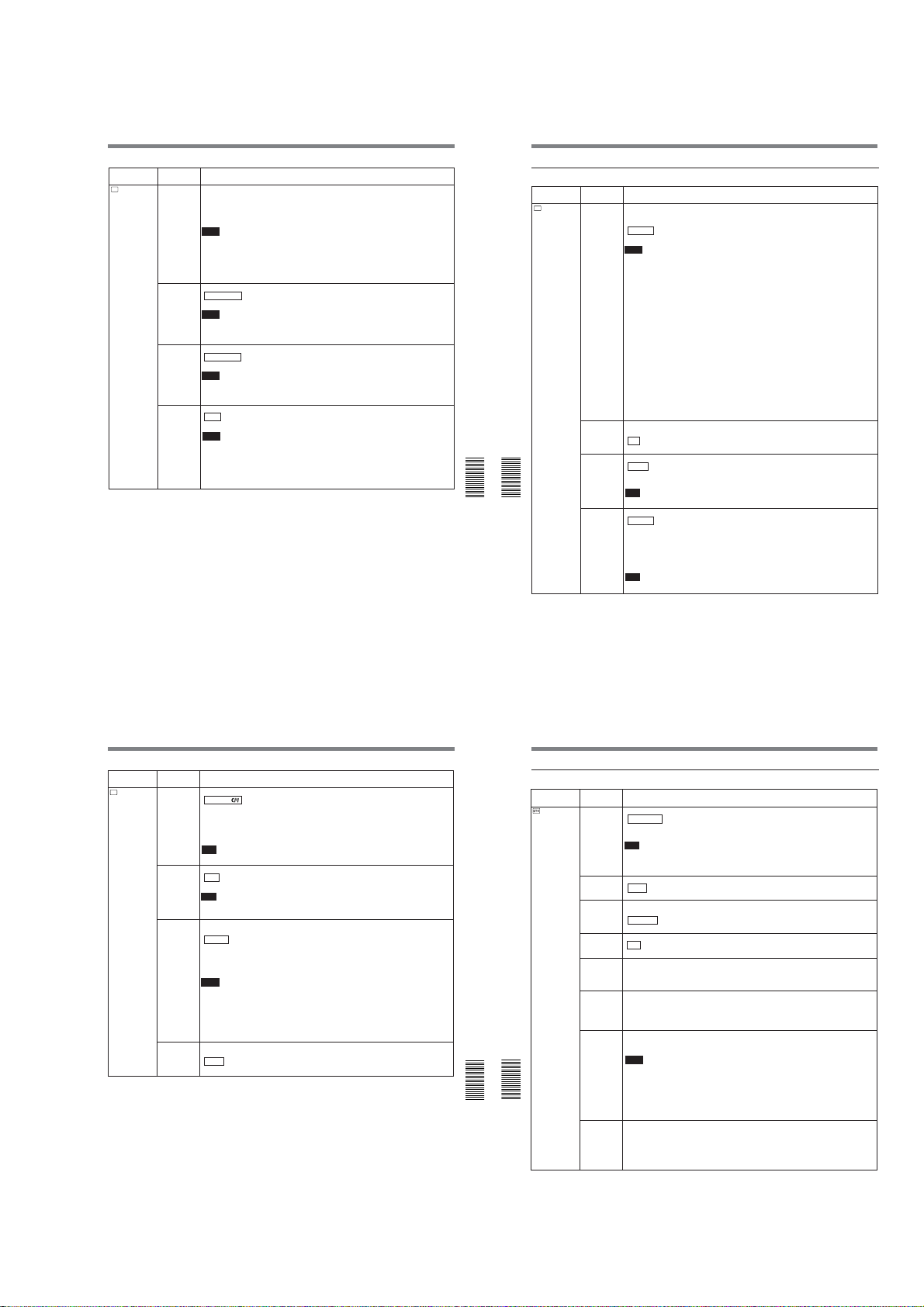
Operating the Menus
DSR-45/45P
Icon/Menu
A
AUDIO SET
Submenu
Setting
(page)
Switches the center levels of the audio level meters displayed on the fine audio levels
REF LEVEL
(page 29 (GB))
screen.
–12dB: Sets the level to –12 dB.
–18dB: Sets the level to –18 dB.
–20dB: Sets the level to –20 dB.
Notes
• The default is –20 dB for DSR-45; –18 dB for DSR-45P.
• The standard output level of the AUDIO OUT connectors is +4 dBu. This is equivalent to
–20 dB for the DSR-45, or –18 dB for the DSR-45P from full bit (maximum audio level).
This level is fixed and does not change even if you change this item setting.
• Changing this level does not change the audio gain of this unit. Turn the AUDIO REC
LEVEL control knobs to adjust the recording level accordingly.
AGC CH1,2
Links/separates the AGC (Auto Gain Control) in channels 1 and 2.
SEPARATE : AGC is not linked. (Channels 1 and 2 sound gains are separated.)
(page 29 (GB))
LINKED: AGC is linked. (Channels 1 and 2 sound gains are linked as a pair.)
Notes
• This setting is disabled when inputting signals from the DV jack.
• The LINKED setting changes to enabled after you set the AUDIO INPUT switch on the
front panel to AUTO.
AGC CH3, 4
Links/separates the AGC (Auto Gain Control) in channels 3 and 4.
(page 29 (GB))
SEPARATE : AGC is not linked. (Channels 3 and 4 sound gains are separated.)
LINKED: AGC is linked. (Channels 3 and 4 sound gains are linked as a pair.)
Notes
• This setting is disabled when inputting signals from the DV jack.
• The LINKED setting changes to enabled after you set the AUDIO INPUT switch on the
front panel to AUTO.
LIMITER
Turns the limiter on/off.
OFF : No limiter
ON: Uses the limiter.
Notes
• This setting is disabled when inputting signals from the DV jack.
• This setting is available only when you have set the AUDIO INPUT switch on the front
panel to MANU.
• Make sure to set the INPUT LEVEL selector on the rear panel correctly. Even if you have
set this item to ON, the limiter will not work for a sound that exceeds the dynamic range of
the input amplifier.
VTR SET menu
Icon/Menu
VTR
VTR SET
Chapter 6 Adjusting and Setting Through Menus
Chapter 6 Adjusting and Setting Through Menus
Submenu
Setting
(page)
Switches the recording mode between DVCAM and DV (SP mode only). When you play
REC MODE
back a tape, the DVCAM/DV setting will be automatically switched; you do not need to use
this item.
DVCAM : Records in DVCAM format.
DV SP: Records in DV format (SP mode).
Notes
• The unit can record only in the DVCAM format or in the SP mode of the DV format.
• You cannot change the setting while recording.
• It is recommended that you record in the DVCAM format. There are some limitations with
respect to DV recording depending on machine specifications and the consumer DV
format as follows:
– The head system is optimized for DVCAM recording. A DV recording overwrites the last
track just before the beginning of the recording. As a result, at the border of these two
recorded portions, picture and sound may be distorted.
– The picture and sound will be recorded unsynchronized. (unlock mode)
– The time code is fixed to the drop frame mode. (only for DSR-45)
– The DV IN TC setting on the TC/UB SET menu becomes invalid. The unit records
internal time code.
• If you dub a consumer DV tape from the DV jack on this unit, keep the following in mind:
– Set REC MODE to DV SP. If REC MODE has been set to DVCAM, a tape with an
invalid format (recording speed: DVCAM, sound: unsynchronized, unlock mode) will be
made. (The unit cannot convert unlock mode sound to lock mode sound.)
– If you edit a tape with an invalid format in the DSR-70/70P, DSR-70A/70AP, DSR-80/
80P, DSR-85/85P, DSR-1800/1800P, DSR-2000/2000P, etc., there may be some
restrictions.
For details on DVCAM/DV format compatibility, see “Compatibility of DVCAM and DV
Format” on page 101 (GB).
AUTO INDEX
Selects whether or not the unit automatically marks an index signal when the unit in the
(page 44 (GB))
stop mode starts recording.
ON : Marks an index signal at the beginning of the recording.
OFF: Does not mark an index signal at the beginning of the recording.
STILL PICT Switches the image displayed in the still mode.
AUTO : Displays an optimized image according to the movement in the image.
FIELD: Displays a field image.
FRAME: Displays a frame image.
Note
If you select FIELD, the image of field 2 is displayed.
FF/REW SPD Selects the tape transport mode in fast-forward and rewind.
FF/REW : Fast-forwards or rewinds the tape at maximum speed without displaying the
picture.
SHUTTLEMAX: Fast-forwards or rewinds the tape at maximum speed (DVCAM: about 14
times normal speed for the DSR-45; about 17 times normal speed for the DSR-45P)
while displaying the picture. However, if you use a tape recorded in the SP mode of the
DV format, the maximum tape speed will be about 24 times normal speed, on both
models.
Note
If you intend to edit using an RS-422A connection, set this item to SHUTTLEMAX.
Icon/Menu
VTR
VTR SET
Chapter 6 Adjusting and Setting Through Menus89 (GB)
Submenu
Setting
(page)
DUPLICATE
Switches the duplicate mode.
(page 69 (GB))
AUTOq
: Starts duplication after rewinding the tape to the beginning in the player
and recorder. (The cassette memory is also duplicated.)
AUTOq: Starts duplication after rewinding the tape to the beginning in the player and
recorder. (The cassette memory is not duplicated.)
MANUALq: Duplicates the tape from any point. (The cassette memory is not
duplicated.)
Note
You cannot change the setting of this item during duplication.
DV EE OUT
Selects the output from the DV jack in the EE mode.
(page 42 (GB))
STILL TIME
FROM STILL Selects the tape protection mode to which the unit switches after the still mode continues for
OFF : Outputs only the playback video and audio signals from the DV jack.
ON: Outputs the selected analog input signals from the DV jack.
Note
When you connect a computer to the DV jack, depending on your computer software, the
selected analog input signals may be output to the computer even if this item is set to OFF.
Selects the length of time that elapses before switching to the tape protection mode from
the still mode.
30 SEC : 30 seconds
1 MIN: 1 minute
2 MIN: 2 minutes
3 MIN: 3 minutes
5 MIN: 5 minutes
Notes
• If the unit is left in playback pause mode for a long time, the tape or the video heads may
be damaged or the video heads may become clogged. Select the shortest time possible
—particularly when using a Mini-DV cassette that is longer than 60 minutes, select 30
SEC or 1 MIN.
• If you change the setting of this item while the unit is in the playback pause mode, the first
tape protection mode change uses the time setting from before the settings were changed.
From the second tape protection mode change, the new time setting is used.
the time interval set in STILL TIME.
STOP : Stops the tape.
STEP FWD: Forwards one frame.
90
(GB) Chapter 6 Adjusting and Setting Through Menus
Operating the Menus
OTHERS menu
Icon/Menu
OTHERS
Chapter 6 Adjusting and Setting Through Menus
Chapter 6 Adjusting and Setting Through Menus
Submenu
Setting
(page)
Selects the control device.
COMMANDER
WIRELESS : Enables the control of the Remote Commander.
(page 26 (GB))
CONTROL S: Enables the control of the Remote Control Unit (DSRM-20, not supplied)
connected to the CONTROL S IN jack. (The Remote Commander is disabled.)
Note
The unit accepts signals from any Sony Remote Commander whose command mode is set
to VTR4, not only the supplied one. If you want to disable the control from any Remote
Commander, set this item to CONTROL S.
AC ON
Switches the state into which the unit goes when the unit is connected to an AC outlet.
MODE
STBY : Makes the unit go into the standby mode.
POWER ON: Turns the unit on.
AUTO STBY Selects whether the unit goes into the standby mode or not, if the unit has been in the stop
mode and no key operations have been attempted for more than one hour.
DISABLE : Leaves the unit in the stop mode.
ENABLE: Makes the unit go into the standby mode.
Selects whether or not the unit beeps.
BEEP
ON : Enables the beep.
OFF: Disables the beep.
LCD BRIGHT
Adjusts the LCD monitor brightness. Press the J/j buttons and the EXEC button to adjust
and set the brightness. You can also adjust the brightness by pressing the J/j buttons on
the Data screen. (The triangle under the bar is displayed in green when the setting is set to
the factory preset value.)
LCD COLOR
Adjusts the depth of color of the LCD monitor. Press the J/j buttons and the EXEC button
(for the DSR-
to adjust and set the depth of color. (The triangle under the bar is displayed in green when
45) / LCD
the setting is set to the factory preset value.)
COLOUR (for
the DSR-45P)
Sets the internal clock of the unit.
CLOCK SET
Pressing the J/j buttons and the EXEC button, set the time (year, month, day, hour and
minute). (When you set the minute, the second count will start from 00.)
Notes
• Regardless of the DATE DISP setting, the date is displayed in the Y/M/D format while you
are setting CLOCK SET.
• The internal backup battery will be fully charged in about 8 hours when power is provided
to the unit. A fully charged internal backup battery can run the internal clock for about two
weeks without the power provided through the AC power cord.
• If the unit starts recording while you are setting this item, the value at that time is set in the
internal clock.
Displays the accumulated time counts (by the digital hours meter) in units of 10 hours or 10
HRS METER
(page 100 (GB))
counts.
OPERATION: Power supplied duration
DRUM RUN: Drum rotation duration
TAPE RUN: Tape run duration
THREADING: Tape unthreading count
Chapter 6 Adjusting and Setting Through Menus91 (GB)
1-21
92
(GB) Chapter 6 Adjusting and Setting Through Menus
 Loading...