

Sony DSR-250, DSR-250P Service manual
DSR-250/250P
RMT-811
Ver 1.2 2001. 11
SERVICE MANUALSERVICE MANUAL
Photo : DSR-250
RMT-811
NTSC model : DSR-250
PAL model : DSR-250P
SPECIFICATIONS
Video camera
recorder
System
Video recording system
2 rotary heads
Helical scanning system
Audio recording system
Rotary heads, PCM system
Quantization: Fs32 kHz (12 bits,
channels 1/2, channels 3/4),
Fs48 kHz (16 bits, channels 1/2)
Video signal
NTSC color, EIA standards (DSR-250),
PAL colour, CCIR standards
(DSR-250P)
Usable cassette
DVCAM cassette with the
mark printed
Mini DVCAM cassette with the
mark printed
DV cassette with the
printed
Mini DV cassette with the
mark printed
Tape speed
DVCAM format:
Approx. 28.218 mm/s
DV format SP mode: Approx.
18.812 mm/s
Recording/playback time
DVCAM format: 184 min (using
cassette PDV-184ME)
DV format SP mode: 270 min
(using cassette PDV-184ME)
Fast-forward/rewind time
Approx. 45 s (using cassette
DVM60/PDVM-40ME)
Approx. 2 min 30 s (using cassette
PDV-184ME)
mark
Viewfinder
Electric viewfinder (B&W)
Image device
1/3 type CCD (3 Charge Coupled
Device) Approx. 380 000 pixels
(Effective: Approx. 340 000 pixels)
(DSR-250), Approx. 450 000 pixels
(Ef
fective: Approx. 400 000 pixels)
(DSR-250P)
Lens
Combined power zoom lens
Filter diameter 58 mm (2 3/8 in)
12× (Optical), 48× (Digital)
F1.6 - 2.4
Focal length
6 - 72 mm (1/4 - 2 7/8 in)
When converted to a 35 mm still
camera
43.2 - 518.4 mm (1 3/4 - 20 1/2 in)
Colour temperature
Auto, nIndoor (3 200 K),
Outdoor (5 800 K), (A, B)
Minimum illumination
2 lux (F1.6)
Input/Output connectors
VIDEO IN/OUT
Input/output auto switch
RCA pin-jack, 1 Vp-p, 75 ohms,
unbalanced, sync negative
S VIDEO
Input/output auto switch
4-pin mini DIN
Luminance signal: 1 Vp-p,
75 ohms, unbalanced
Chrominance signal: 0.286 Vp-p
(DSR-250), 0.3 Vp-p (DSR-250P),
75 ohms, unbalanced
AUDIO IN/OUT CH-1/CH-2
Input/output auto switch
RCA pin-jack, 245 mV, (at output
impedance more than 47 kilohms)
Output impedance with less than
2.2 kilohms
Input impedance more than
47 kilohms
AUDIO IN CH1/CH2
XLR 3-pin, female
–60 dBu: 6.8 kilohms,
+4 dBu: 6.8 kilohms
(0 dBu = 0.775 Vrms)
PHONES
Stereo minijack (ø 3.5 mm)
Stereo mini-minijack (ø 2.5 mm)
MIC IN +48V
XLR 3-pin, female
VF
20-pin
LIGHT
2-pin
DV IN/OUT
6-pin connector
Speaker
Dynamic speaker (ø 20 mm)
DC IN 12V
XLR 4-pin, female
DC OUT 12V
4-pin, male
LCD screen
Picture
2.5 type measured diagonally
49.9 × 37.3 mm (2 × 1 1/2 in)
Total dot number
200 640 (880 × 228)
LANC control jack
US Model
Canadian Model
DSR-250
AEP Model
DSR-250P
R MECHANISM
General
Peak inrush current (DSR-250P)
(1) Hot switching inrush current,
measured in accordance with
European standard EN55103-1:
6.3 A (230 V)
Power requirements
14.4 V (Lithium-ion battery pack)
12 to 17 V (AC power adaptor)
Average power consumption
(when using the battery pack)
During camera recording using
LCD
12.1 W
Viewfinder
10.5 W
Operating temperature
0 °C to 40 °C (32 °F to 104 °F)
Storage temperature
–20 °C to +60 °C (–4 °F to +140 °F)
Dimensions (approx.)
242 × 251 × 509 mm (9 5/8 × 10 ×
20 1/8 in) (w/h/d)
Mass (approx.)
3.5 kg (7 lb 11 oz)
main unit only
4.9 kg (10 lb 13 oz)
including the BP-L40 (A) battery
pack, cassette PDV-184ME,
microphone, viewfinder, and
hood cap
Supplied accessories
See page 2.
— Continued on next page —
DIGITAL CAMCORDER

“Memory Stick”
Memory
Flash memory
4MB: MSA-4A
Operating voltage
2.7 V -3.6 V
Power consumption
Approx. 45 mA in the operating
mode
Approx. 130 µA in the standby
mode
Dimensions (approx.)
50 × 2.8 × 21.5 mm
(2 × 1/8 × 7/8 in) (w/h/d)
Mass (approx.)
4 g (0.14 oz)
Design and specifications are
subject to change without notice.
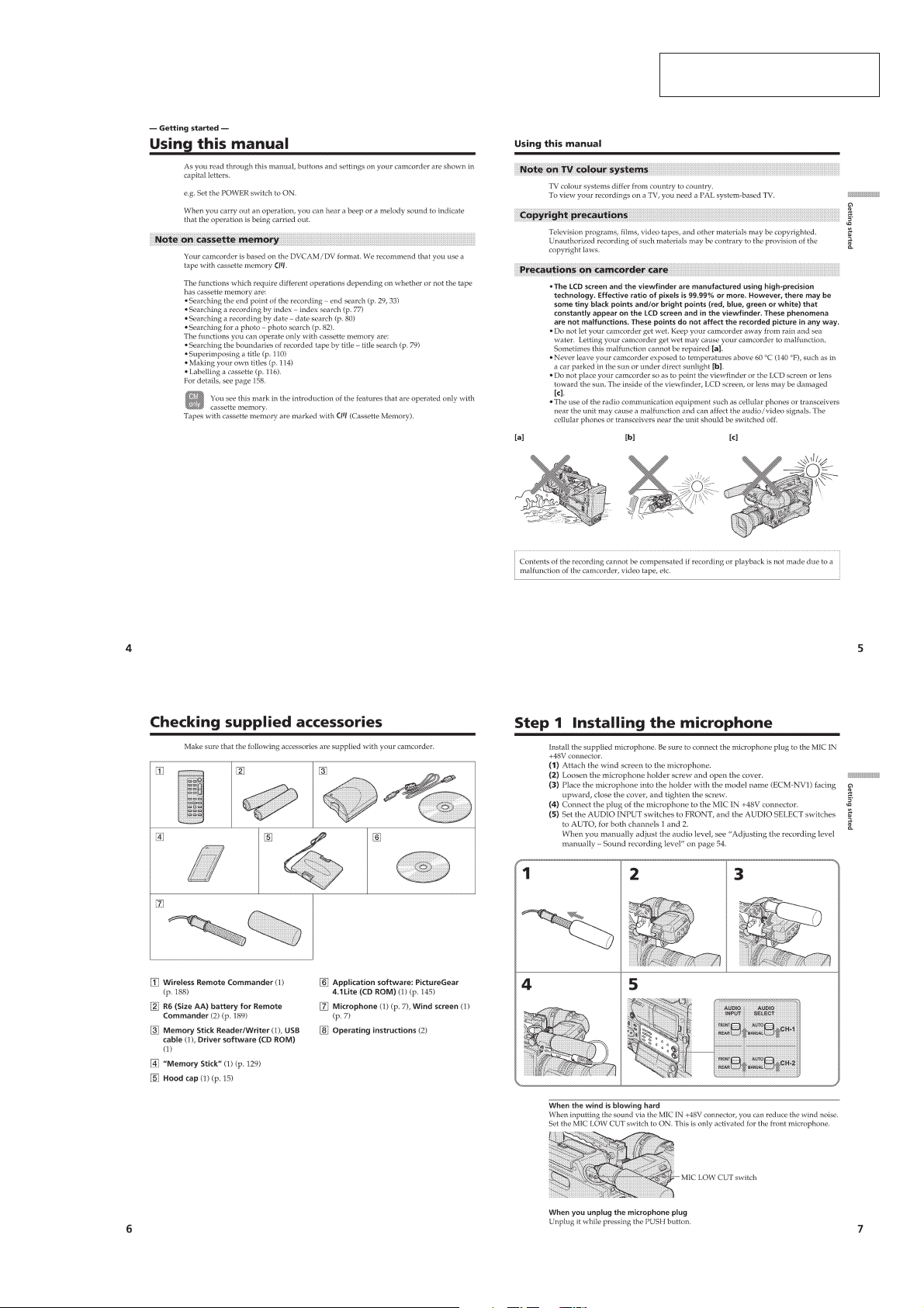
• SUPPLIED ACCESSORIES
Check that the following accessories are supplied with your
camcorder.
12 3
4
7
56
SAFETY-RELATED COMPONENT WARNING!!
COMPONENTS IDENTIFIED BY MARK 0 OR DOTTED LINE WITH
MARK 0 ON THE SCHEMATIC DIAGRAMS AND IN THE PARTS
LIST ARE CRITICAL TO SAFE OPERATION. REPLACE THESE
COMPONENTS WITH SONY PARTS WHOSE PART NUMBERS
APPEAR AS SHOWN IN THIS MANUAL OR IN SUPPLEMENTS
PUBLISHED BY SONY.
1 WirelessRemote Commander (1)
2 R6 (Size AA) battery for Remote
Commander (2)
3 Memory Stick Reader/Writer (1), USB
cable (1), Driver software (CD ROM)
(1)
4 “Memory Stick” (1)
5 Hood cap (1)
6 Application software: PictureGear
4.1Lite (CD ROM) (1)
7 Microphone(1), Wind screen (1)
8 Operating instructions (2)
ATTENTION AU COMPOSANT AYANT RAPPORT
À LA SÉCURITÉ!
LES COMPOSANTS IDENTIFÉS P AR UNE MARQUE 0 SUR LES
DIAGRAMMES SCHÉMA TIQUES ET LA LISTE DES PIÈCES SONT
CRITIQUES POUR LA SÉCURITÉ DE FONCTIONNEMENT. NE
REMPLACER CES COMPOSANTS QUE PAR DES PIÈSES SONY
DONT LES NUMÉROS SONT DONNÉS DANS CE MANUEL OU
DANS LES SUPPÉMENTS PUBLIÉS PAR SONY.
SAFETY CHECK-OUT
After correcting the original service problem, perform the following
safety checks before releasing the set to the customer.
1. Check the area of your repair for unsoldered or poorly-soldered
connections. Check the entire board surface for solder splashes
and bridges.
2. Check the interboard wiring to ensure that no wires are
"pinched" or contact high-wattage resistors.
3. Look for unauthorized replacement parts, particularly
transistors, that were installed during a previous repair . Point
them out to the customer and recommend their replacement.
4. Look for parts which, through functioning, show obvious signs
of deterioration. Point them out to the customer and
recommend their replacement.
5. Check the B+ voltage to see it is at the values specified.
6. Flexible Circuit Board Repairing
• Keep the temperature of the soldering iron around 270˚C
during repairing.
• Do not touch the soldering iron on the same conductor of the
circuit board (within 3 times).
• Be careful not to apply force on the conductor when soldering
or unsoldering.
— 2 —

TABLE OF CONTENTS
SERVICE NOTE
1. TO TAKE OUT A CASSETTE WHEN NOT EJECT
(FORCE EJECT) ································································ 8
SELF-DIAGNOSIS FUNCTION
1. SELF-DIAGNOSIS FUNCTION······································· 9
2. SELF-DIAGNOSIS DISPLAY ·········································· 9
3. SERVICE MODE DISPLAY ·············································9
3-1. Display Method ·································································· 9
3-2. Switching of Backup No. ··················································· 9
3-3. End of Display···································································· 9
4. SELF-DIAGNOSIS CODE TABLE································· 10
1. GENERAL
Getting started
Using this manual ··································································1-1
Checking supplied accessories ··············································1-1
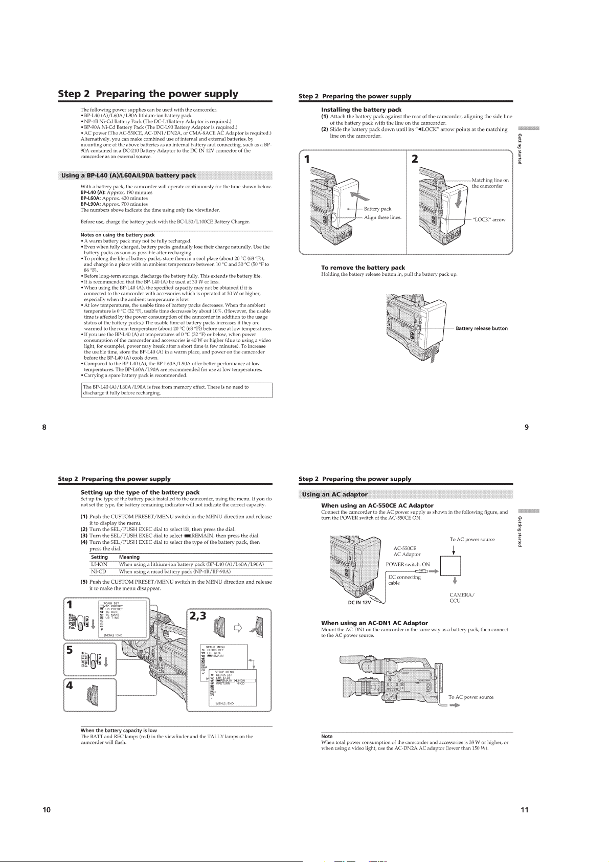
Step 1 Installing the microphone ···········································1-1
Step 2 Preparing the power supply ········································1-2
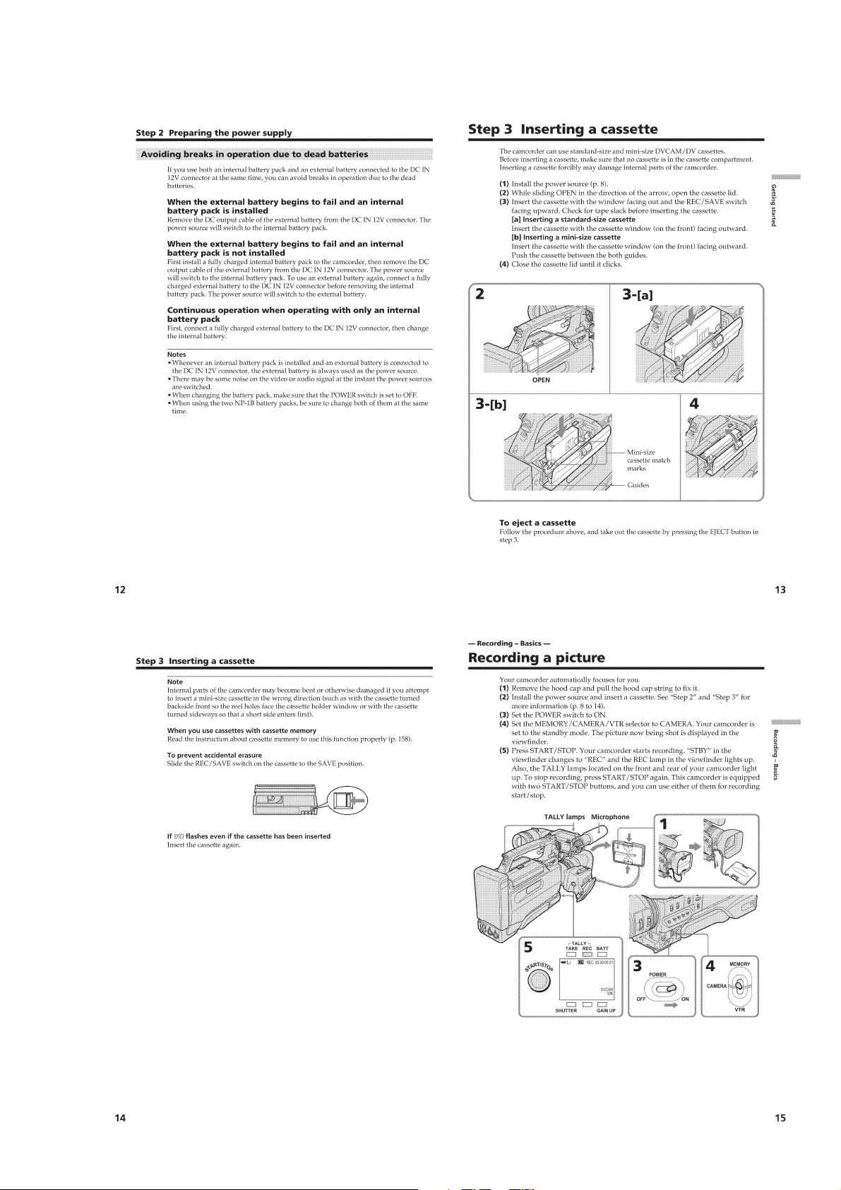
Step 3 Inserting a cassette······················································1-3
Recording – Basics
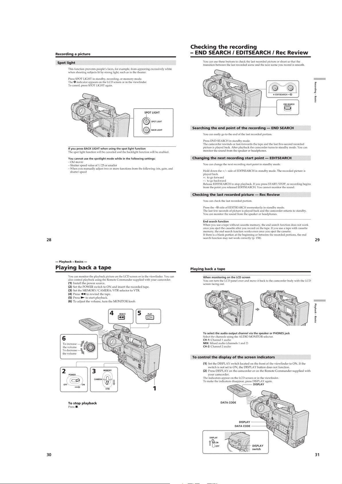
Recording a picture································································1-3
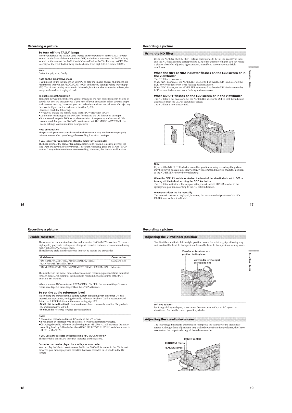
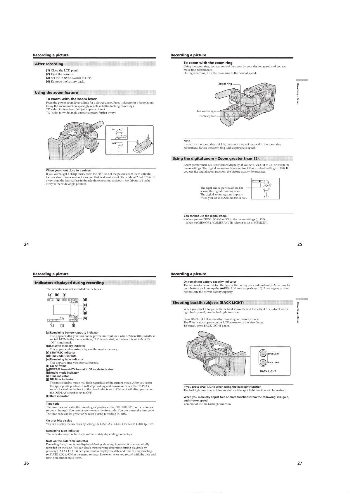
Shooting backlit subjects (BACK LIGHT) ·························1-6
Spot light·············································································1-7
Checking the recording – END SEARCH / EDITSEARCH /
Rec Review ·········································································1-7
Playback – Basics
Playing back a tape ································································1-7
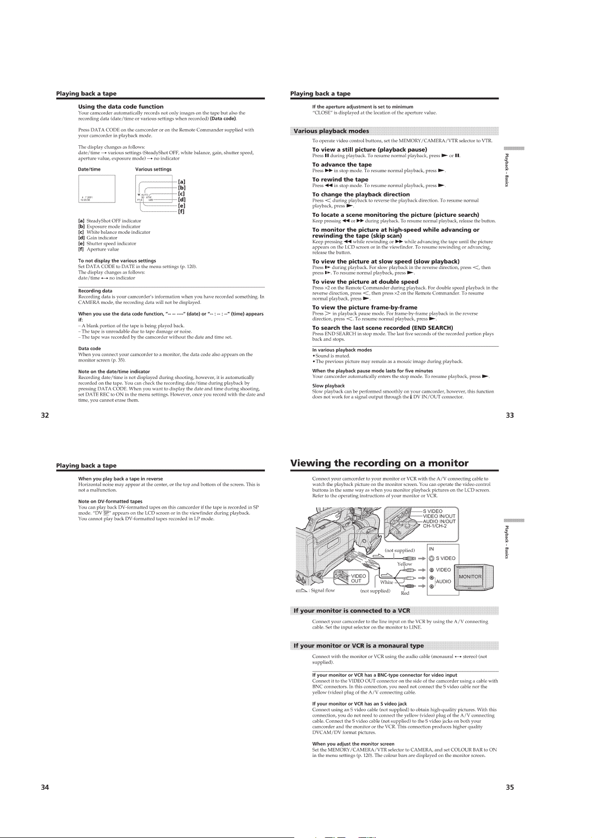
Viewing the recording on a monitor ······································1-8
Advanced Recording Operations
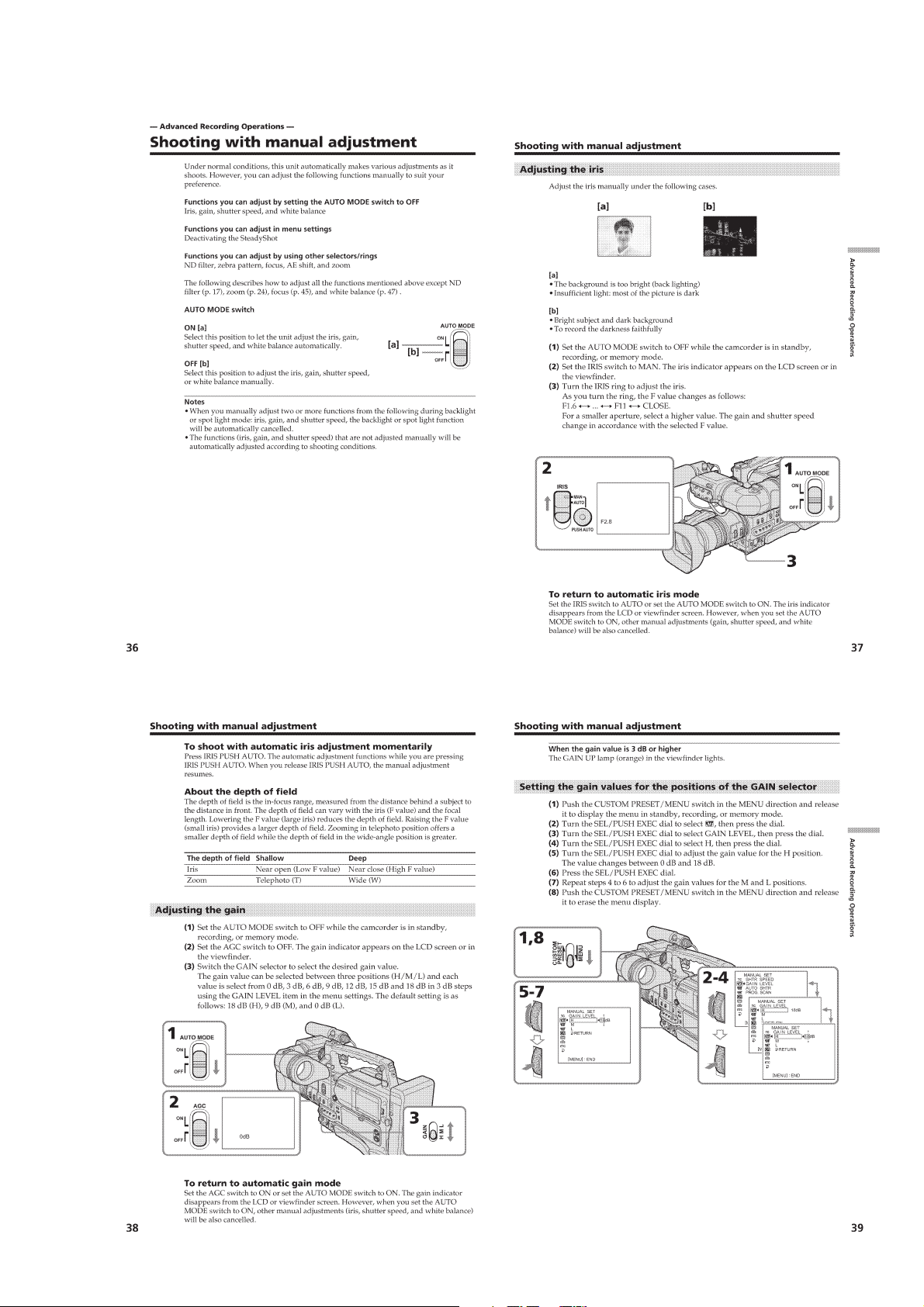
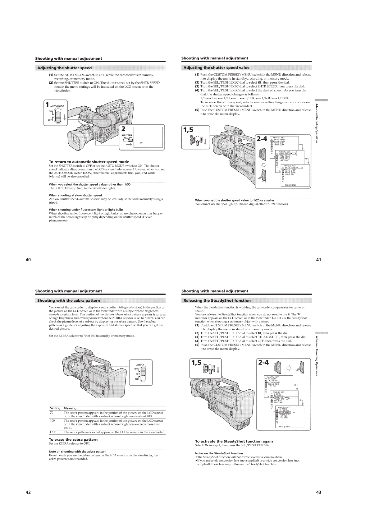
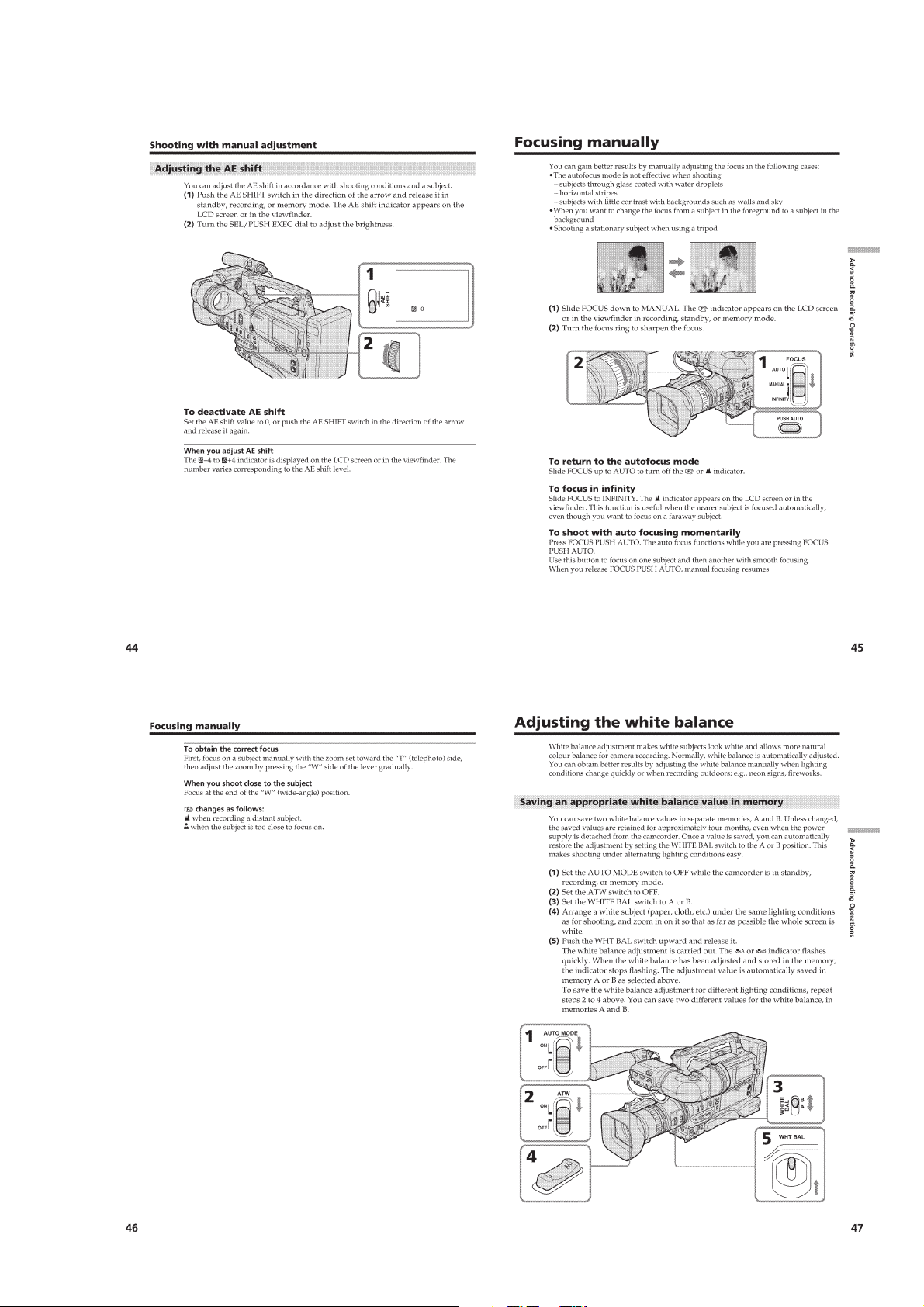
Shooting with manual adjustment ·········································1-9
Focusing manually·······························································1-11
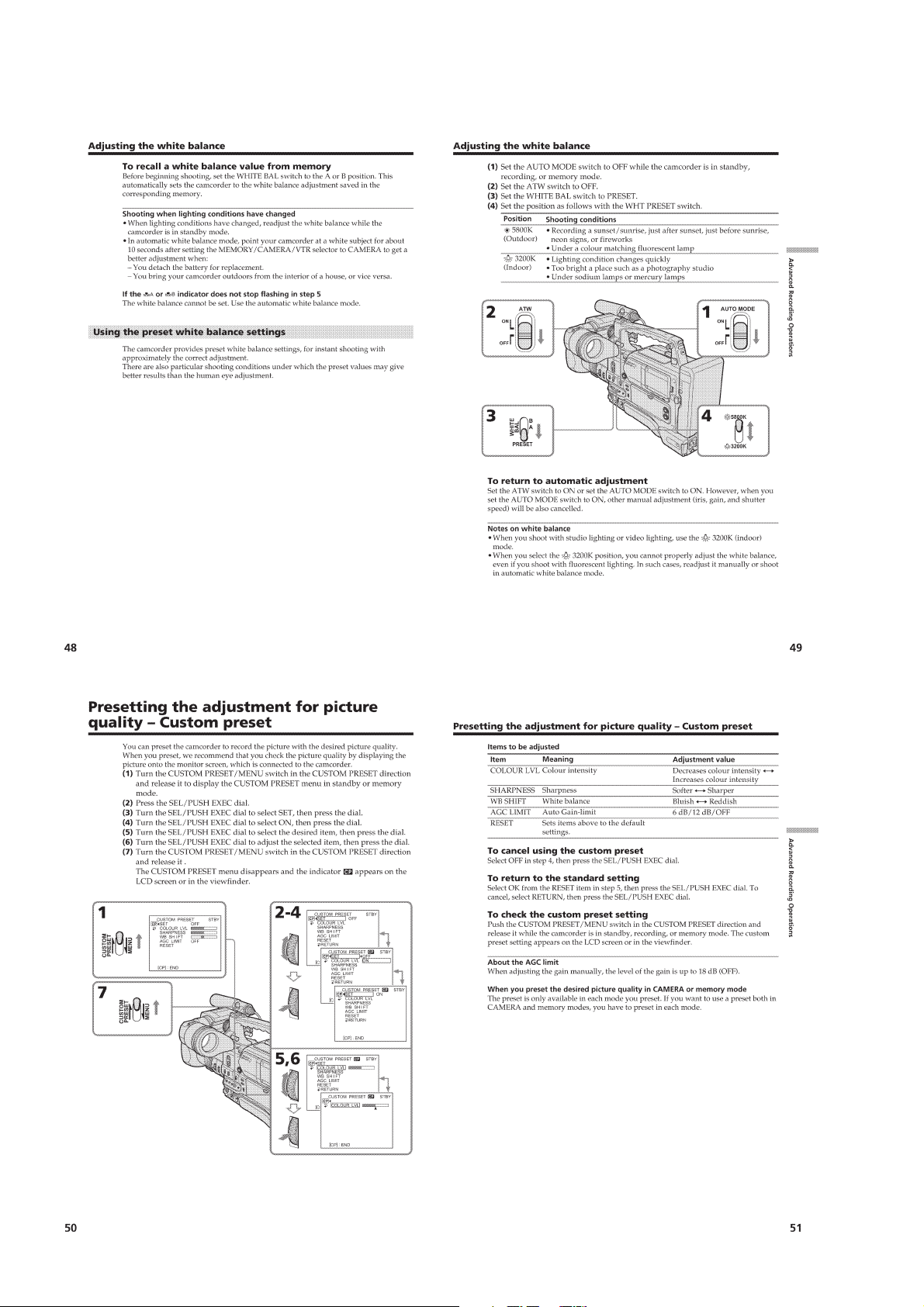
Adjusting the white balance·················································1-11
Presetting the adjustment for picture quality – Custom preset ··· 1-12
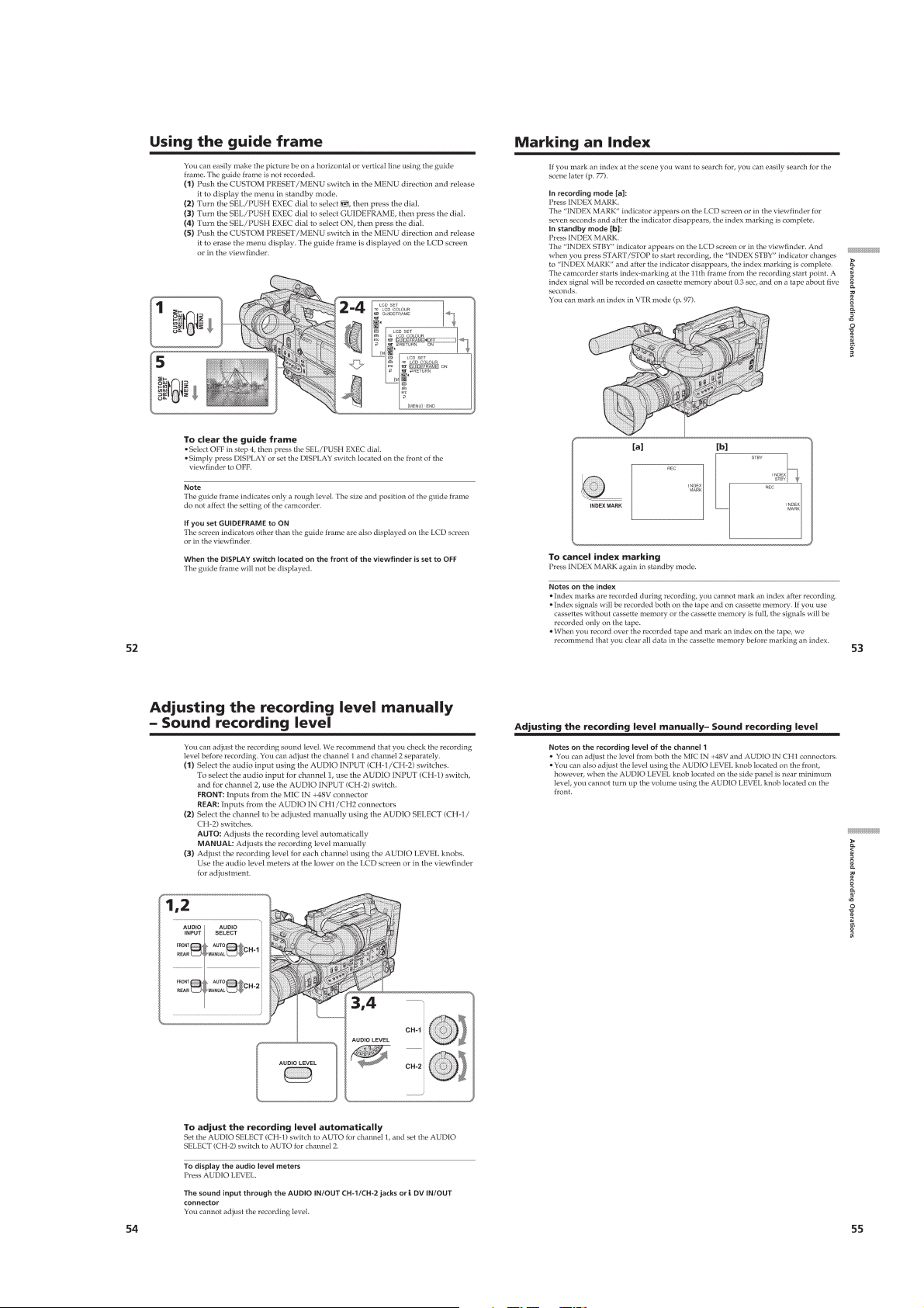
Using the guide frame·························································· 1-13
Marking an Index·································································1-13
Adjusting the recording level manually
– Sound recording level ····················································1-13
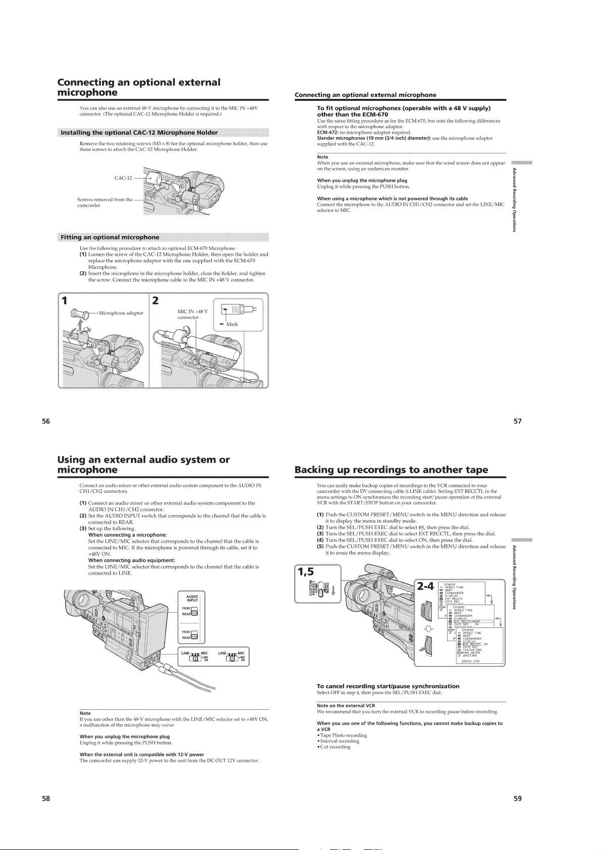
Connecting an optional external microphone ······················1-14
Using an external audio system or microphone···················1-14
Backing up recordings to another tape ································1-14
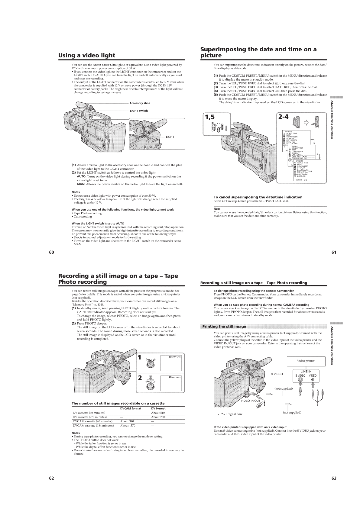
Using a video light·······························································1-15
Superimposing the date and time on a picture·····················1-15
Recording a still image on a tape – Tape Photo recording ··1-15
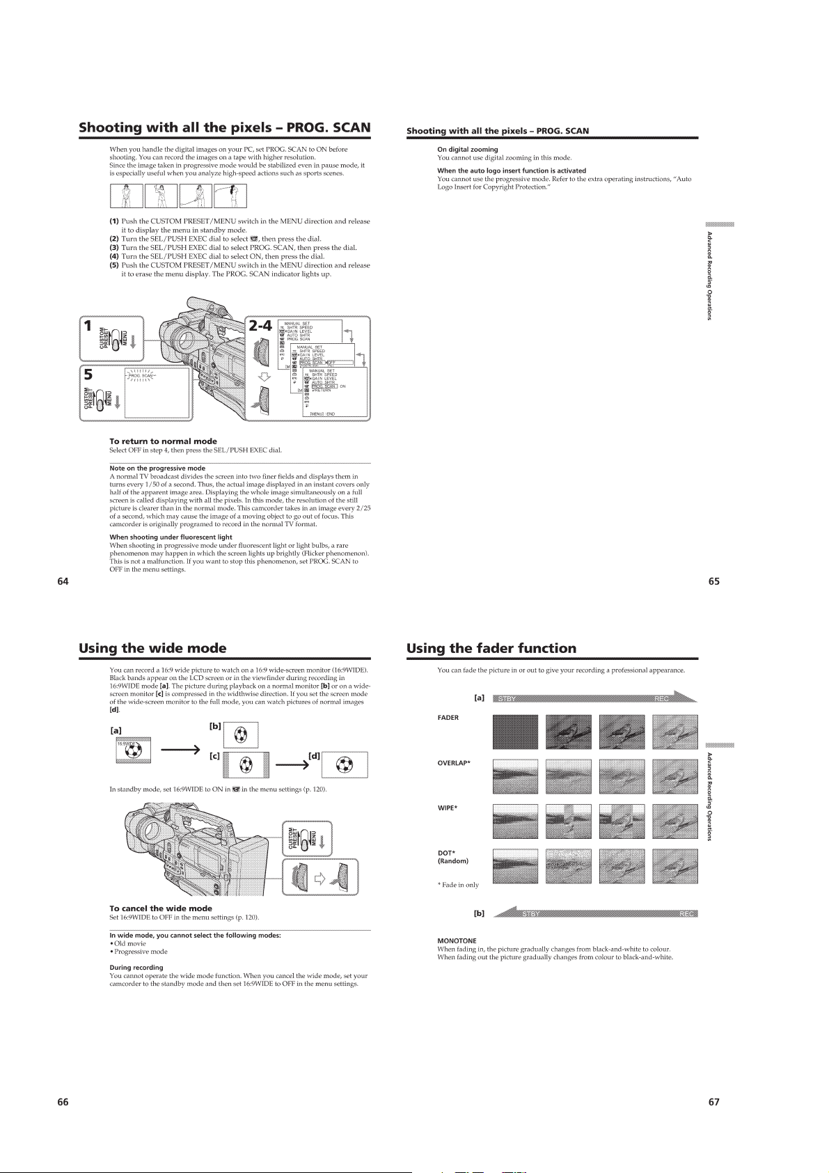
Shooting with all the pixels – PROG.SCAN ·······················1-16
Using the wide mode ···························································1-16
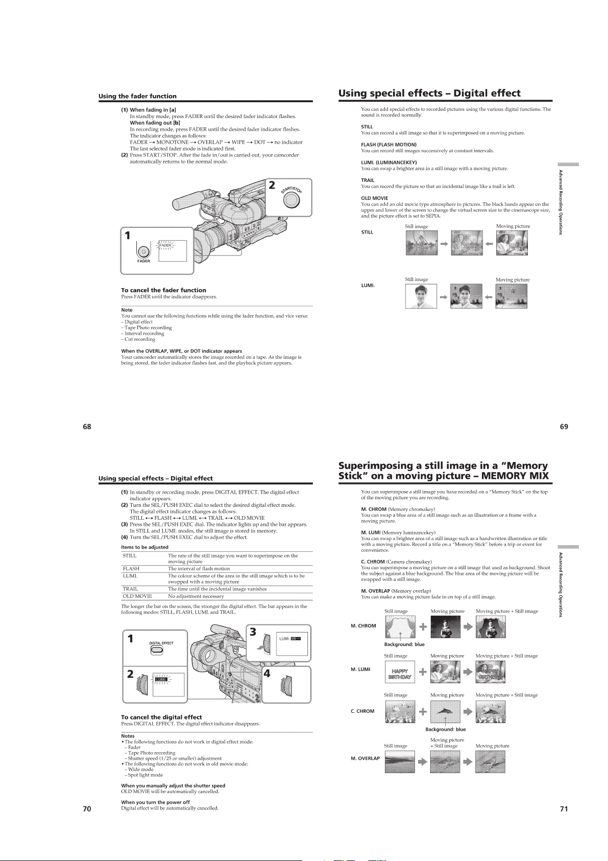
Using the fader function ······················································1-16
Using special effects – Digital effect···································1-17
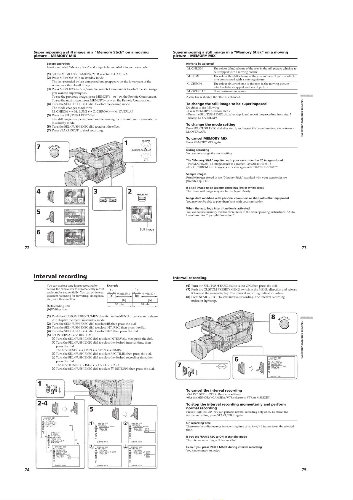
Superimposing a still image in a “Memory Stick ”
on a moving picture – MEMORY MIX ····························1-17
Interval recording·································································1-18
Frame by frame recording – Cut recording ·························1-19
Advanced Playback Operations
Searching for a recording by index – Index search ·············1-19
Searching the boundaries of recorded tape by title
– Title search·····································································1-19
Searching a recording by date – Date search·······················1-20
Searching for a photo – Photo search/Photo scan················ 1-20
Playing back a tape with digital effects ······························· 1-21
Editing
Dubbing a tape ·····································································1-21
Dubbing only desired scenes – Digital program editing ·····1-22
Using with an analog video unit and a PC
– Signal convert function··················································1-23
Recording video or TV programs ········································1-24
Audio dubbing ·····································································1-25
Setting time values······························································· 1-26
Superimposing a title ···························································1-27
Making your own titles ························································1-28
Labelling a cassette······························································1-29
Erasing the cassette memory data········································1-29
Customizing Y our Camcorder
Changing the menu settings·················································1-30
Resetting the date and time··················································1-32
“Memory Stick” Operations
Using a “Memory Stick ” – introduction ·····························1-32
Recording still images on a “Memory Stick ”
– Memory Photo recording ···············································1-33
Recording an image from a tape as a still image ·················1-34
Copying still images from a tape – Photo save····················1-35
Viewing a still picture – Memory Photo playback ·············· 1-35
Copying an image recorded on a “Memory Stick ” to tapes ··1-36
Playing back images continuously – SLIDE SHOW···········1-37
Preventing accidental erasure – Image protection ···············1-37
Deleting images ···································································1-37
Writing a print mark – Print mark ·······································1-38
Additional Information
Compatibility of DVCAM and DV formats ························1-39
Usable cassettes ···································································1-39
About i.LINK·······································································1-40
Troubleshooting ···································································1-40
Self-diagnosis display ··························································1-42
Warning indicators and messages ········································1-42
Using your camcorder abroad·············································· 1-42
Maintenance information and precautions···························1-43
Quick Reference
Identifying the parts and controls ········································1-44
Quick Function Guide ·····························································1-47
Auto Logo Insert for Copyright Protection ·····························1-48
Introduction –Auto Logo Insert ···········································1-48
Preparing a logo file·····························································1-48
Registering your password ··················································1-48
Registering a still image to be used as a logo ······················1-49
Deactivating the auto logo insert function···························1-50
Changing or resetting the setup ···········································1-50
Precautions concerning the auto logo insert function··········1-51
2. DISASSEMBLY
2-1. LCD SECTION (PD-126 BOARD, INVERTER
TRANSFORMER UNIT)················································2-2
2-2. CARRYING HANDLE SECTION
(TH-010, ME-019 BOARDS, VF SHOE BASE) ············2-3
2-3. VF SECTION (MAIN, SUB BOARDS)························· 2-4
2-4.
CABINET (R) BLOCK ASSEMBLY (SW-343 BO ARD) ·
2-5. HINGE SECTION
(HINGE ASSEMBLY, FP-241 FLEXIBLE BOARD) ····2-6
2-6. CABINET (L) ASSEMBLY, MECHANISM DECK ······2-7
2-7. DD-146, IN-057 BOARDS ·············································2-8
2-8. VI-156 BOARD·······························································2-9
2-9. LENS BLOCK ASSEMBLY (ON-001, NO-001 BOARDS,
CONTROL SWITCH BLOCK (CF-1044)) ··················2-10
2-10. LENS BLOCK ASSEMBLY (LENS CABINET (R)) ··2-11
2-11. XL-003, VO-012, DV-031, RL-057 BOARDS ·············2-13
2-12. FS-082 BOARD, 4P CONNECTOR (WITH DC SW) ···2-13
2-13. CIRCUIT BOARDS LOCATION ·································2-15
2-14. FLEXIBLE BOARDS LOCATION ······························2-16
2-5
3. BLOCK DIAGRAMS
3-1. OVERALL BLOCK DIAGRAM (1/5) ···························3-1
3-2. OVERALL BLOCK DIAGRAM (2/5) ···························3-3
3-3. OVERALL BLOCK DIAGRAM (3/5) ···························3-5
3-4. OVERALL BLOCK DIAGRAM (4/5) ···························3-7
3-5. OVERALL BLOCK DIAGRAM (5/5) ···························3-9
3-6. POWER BLOCK DIAGRAM (1/4)······························3-11
— 3 —

3-7. POWER BLOCK DIAGRAM (2/4) ······························3-13
3-8. POWER BLOCK DIAGRAM (3/4) ······························3-15
3-9. POWER BLOCK DIAGRAM (4/4) ······························3-17
4. PRINTED WIRING BOARDS AND
SCHEMATIC DIAGRAMS
4-1. FRAME SCHEMATIC DIAGRAM (1/3)·······················4-1
FRAME SCHEMATIC DIAGRAM (2/3)·······················4-3
FRAME SCHEMATIC DIAGRAM (3/3)·······················4-5
4-2. PRINTED WIRING BOARDS AND
SCHEMATIC DIAGRAMS ············································ 4-8
• CD-274 (CCD IMAGER)
SCHEMATIC DIAGRAM ······························4-9
• CD-274 (CCD IMAGER)
PRINTED WIRING BOARD ·······················4-11
• VI-156 (CAMERA)(1/25)
SCHEMATIC DIAGRAM ····························4-13
• VI-156 (CAMERA-2)(2/25)
SCHEMATIC DIAGRAM ····························4-15
• VI-156 (MS INTERFACE)(3/25)
SCHEMATIC DIAGRAM ····························4-17
• VI-156 (RS232C I/F, STILL CONTROL)(4/25)
SCHEMATIC DIAGRAM ····························4-19
• VI-156 (DV SIGNAL PROCESSOR)(5/25)
SCHEMATIC DIAGRAM ····························4-21
• VI-156 (DV INTERFACE)(6/25)
SCHEMATIC DIAGRAM ····························4-23
• VI-156 (LINE IN/OUT)(7/25)
SCHEMATIC DIAGRAM ····························4-25
• VI-156 (LINE A/D CONV.)(8/25)
SCHEMATIC DIAGRAM ····························4-27
• VI-156 (MECHA CONTROL)(9/25)
SCHEMATIC DIAGRAM ····························4-29
• VI-156 (SERVO)(10/25)
SCHEMATIC DIAGRAM ····························4-31
• VI-156 (SERVO-2)(11/25)
SCHEMATIC DIAGRAM ····························4-33
• VI-156 (REC/PB HEAD AMP)(12/25)
SCHEMATIC DIAGRAM ····························4-35
• VI-156 (CAMERA-3)(13/25)
SCHEMATIC DIAGRAM ····························4-37
• VI-156 (ZOOM/FOCUS MOTOR DRIVE)(14/25)
SCHEMATIC DIAGRAM ····························4-39
• VI-156 (LENS DRIVE)(15/25)
SCHEMATIC DIAGRAM ····························4-41
• VI-156 (PARALLEL IN/SERIAL OUT)(16/25)
SCHEMATIC DIAGRAM ····························4-43
• VI-156 (HI CONTROL)(17/25)
SCHEMATIC DIAGRAM ····························4-45
• VI-156 (AUDIO)(18/25)
SCHEMATIC DIAGRAM ····························4-47
• VI-156 (AUDIO-2)(19/25)
SCHEMATIC DIAGRAM ····························4-49
• VI-156 (AUDIO-3)(20/25)
SCHEMATIC DIAGRAM ····························4-51
• VI-156 (AUDIO-4)(21/25)
SCHEMATIC DIAGRAM ····························4-53
• VI-156 (CONNECTOR-1)(22/25)
SCHEMATIC DIAGRAM ····························4-55
• VI-156 (CONNECTOR-2)(23/25),
MS-058 (MS CONNECTOR)
SCHEMATIC DIAGRAMS·························· 4-57
• VI-156 (DD CONVERTER-1)(24/25)
SCHEMATIC DIAGRAM ····························4-59
• VI-156 (DD CONVERTER-2)(25/25)
SCHEMATIC DIAGRAM ····························4-61
• VI-156 (CAMERA, DV/MS INTERFACE, SERVO,
REC/PB HEAD AMP, AUDIO, DD CONV.)
PRINTED WIRING BOARD ·······················4-63
• MS-058 (MS CONNECTOR)
PRINTED WIRING BOARD ·······················4-67
• MD-76 (MODE SENSOR)
PRINTED WIRING BOARD ·······················4-69
• MD-76 (MODE SENSOR)
SCHEMATIC DIAGRAM ····························4-71
• JK-197 (VIDEO/AUDIO IN/OUT),
VO-012 (VIDEO OUT)
PRINTED WIRING BOARDS ·····················4-73
• RL-057 (LANC), DV-031 (DV IN/OUT)
PRINTED WIRING BOARDS ·····················4-75
• JK-197 (VIDEO/AUDIO IN/OUT),
VO-012 (VIDEO OUT), RL-057 (LANC),
DV-031 (DV IN/OUT)
SCHEMATIC DIAGRAMS··························4-77
• KY-049 (VCR FUNCTION), EJ-034 (EJECT)
PRINTED WIRING BOARDS ·····················4-79
• FC-074 (USER FUNCTION),
LL-010 (USER FUNCTION)
PRINTED WIRING BOARDS ·····················4-81
• FS-082 (USER FUNCTION)
PRINTED WIRING BOARD ·······················4-83
• KY-049 (VCR FUNCTION), EJ-034 (EJECT),
FC-074 (USER FUNCTION),
LL-010 (USER FUNCTION),
FS-082 (USER FUNCTION)
SCHEMATIC DIAGRAMS··························4-85
• SW-343 (USER FUNCTION)
PRINTED WIRING BOARD ·······················4-87
• SB-036 (USER FUNCTION),
PM-040 (MODE SELECT)
PRINTED WIRING BOARDS ·····················4-89
• AE-023 (USER FUNCTION),
KP-011 (MENU SELECT)
PRINTED WIRING BOARDS ·····················4-91
• SW-343 (USER FUNCTION),
SB-036 (USER FUNCTION),
AE-023 (USER FUNCTION)
PM-040 (MODE SELECT),
KP-011 (MENU SELECT)
SCHEMATIC DIAGRAMS··························4-93
• PD-126 (RGB DRIVE/TIMING GEN)
PRINTED WIRING BOARD ·······················4-95
• PD-126 (RGB DRIVE/TIMING GEN)
SCHEMATIC DIAGRAM ····························4-97
• SE-116 (VAP SENSOR), ON-001 (RELAY),
NO-001 (RELAY)
PRINTED WIRING BOARDS ·····················4-99
• SE-116 (VAP SENSOR), ON-001 (RELAY),
NO-001 (RELAY)
SCHEMATIC DIAGRAMS························4-101
• HP-129 (HEADPHONE OUT),
TH-010 (SIRCS (REAR))
PRINTED WIRING BOARDS ···················4-103
• HP-129 (HEADPHONE OUT),
TH-010 (SIRCS (REAR)),
CONTROL SWITCH BLOCK (CF-1044/EG-1044)
SCHEMATIC DIAGRAMS························4-105
• ME-019 (MIC AMP, EVF OUT)
PRINTED WIRING BOARD ····················· 4-107
• ME-019 (MIC AMP, EVF OUT)
SCHEMATIC DIAGRAM ··························4-109
• XL-003 (CH1/CH2 MIC AMP)
PRINTED WIRING BOARD ····················· 4-111
— 4 —

• XL-003 (CH1/CH2 MIC AMP)
SCHEMATIC DIAGRAM ··························4-113
• DD-146 (DC-DC CONVERTER),
DC-095 (DC OUT)
PRINTED WIRING BOARDS···················4-115
• IN-057 (DC IN), VL-034 (LIGHT)
PRINTED WIRING BOARDS···················4-117
• DD-146 (DC-DC CONVERTER),
DC-095 (DC OUT), IN-057 (DC IN),
VL-034 (LIGHT)
SCHEMATIC DIAGRAMS························4-119
4-3. WAVEFORMS ····························································4-121
4-4. MOUNTED PARTS LOCATION ·······························4-125
5 ADJUSTMENTS
1. Before starting adjustment···············································5-1
1-1. Adjusting items when replacing main parts and boards.·5-2
5-1. CAMERA SECTION ADJUSTMENT···························5-4
1-1. PREPARATIONS BEFORE ADJUSTMENT
(CAMERA SECTION) ···················································5-4
1-1-1.List of Service Tools ························································5-4
1-1-2.Preparations ·····································································5-6
1-1-3.How to make the DC cable·············································· 5-6
1-1-4.Precaution ········································································5-8
1. Setting the Switch···························································· 5-8
2. Order of Adjustments ······················································ 5-8
3. Subjects ···········································································5-8
1-2. INITIALIZATION OF A, B, C, D, E, F, 8 PAGE DATA 5-9
1-2-1.INITIALIZATION OF A, C, D, 8 PAGE DATA ·············5-9
1. Initializing the C, D, 8 Page Data····································5-9
2. Modification of C, D, 8 Page Data ··································5-9
3. C Page Table ····································································5-9
4. D Page Table··································································5-11
5. 8 Page Table··································································· 5-12
6. Initializing the A Page Data··········································· 5-12
1-2-2.INITIALIZATION OF B PAGE DATA·························5-13
1. Initializing the B Page Data···········································5-13
2. Modification of B Page Data·········································5-13
3. B Page Table ··································································5-13
1-2-3.INITIALIZATION OF E, F PAGE DATA·····················5-14
1. Initializing the E, F Page Data·······································5-14
2. Modification of E, F Page Data ·····································5-14
3. F Page Table ··································································5-14
4. E Page Table ··································································5-15
1-3. CAMERA SYSTEM ADJUSTMENTS························ 5-16
1. 27MHz Origin Oscillation Adjustment (VI-156 board)··· 5-16
2. Zoom Key Center Adjustment ·······································5-16
3. HALL Adjustment ·························································5-17
4. Offset Adjustment··························································5-17
5. Flange Back Adjustment (Using Minipattern Box)·······5-18
6. Flange Back Adjustment
(Using Flange Back Adjustment Chart and Subject
More Than 500m Away)··············································· 5-19
6-1. Flange Back Adjustment (1)··········································5-19
6-2. Flange Back Adjustment (2)··········································5-19
7. Flange Back Check························································ 5-20
8. Picture Frame Setting ···················································· 5-20
9. Pre White Balance Data Input ·······································5-21
10. Auto White Balance Standard Data Input ·····················5-21
11. MAX GAIN Adjustment ···············································5-22
12. LV Standard Data Input················································· 5-22
13. White Balance ND Filter 1 Compensation ····················5-23
14. White Balance ND Filter 2 Compensation ····················5-23
15. Auto White Balance Adjustment ··································· 5-24
16. Color Reproduction Adjustment (ND Filter OFF) ········5-24
17. Color Reproduction Adjustment (ND Filter 1)··············5-25
18. Color Reproduction Adjustment (ND Filter 2)··············5-25
19. White Balance Check ····················································5-26
20. Steady Shot Adjustment ················································5-27
20-1. Steady Shot Adjustment (1)···········································5-28
20-2. Steady Shot Adjustment (2)···········································5-29
1-4. LCD SYSTEM ADJUSTMENT ···································5-30
1. VCO Adjustment (PD-126 board)································· 5-30
2. Bright Adjustment (PD-126 board) ·······························5-31
3. Black Limit Adjustment (PD-126 board) ······················5-31
4. Contrast Adjustment (PD-126 board)····························5-32
5. Center Level Adjustment (PD-126 board) ·····················5-32
6. V-COM Adjustment (PD-126 board) ····························5-33
7. White Balance Adjustment (PD-126 board)··················5-33
5-2. MECHANICAL SECTION ADJUSTMENT ···············5-34
5-2-1.PARTS REPLACEMENT AND PREPARATION FOR
ADJUSTMENT·····························································5-35
2-1-1.ASSEMBLY/DISASSEMBLY OF CASSETTE
COMPARTMENT ·························································5-35
2-1-2.HOW TO LOAD/UNLOAD··········································5-35
2-1-3.About Mode Selector II ·················································5-36
3-1. OUTLINE······································································ 5-36
1. Manual test ····································································5-36
2. Step test ·········································································5-36
3. Auto test ········································································5-36
3-2. MECHANISM CONDITION (POSITION) SHIFTING
ORDER LIST ································································5-36
3-3. MODE SELECTOR II CONNECTION ·······················5-36
5-2-2.PERIODIC CHECK ······················································ 5-37
2-2-1.CLEANING OF ROTARY DRUM ASSEMBLY ·········5-37
2-2-2.CLEANING OF TAPE PATH SYSTEM ······················5-37
2-2-3.PERIODIC CHECKS ····················································5-37
5-2-3.PARTS REPLACEMENT ············································· 5-38
2-3-1.TAPE GUIDE 1/8 AND GUIDE GUARD ····················5-38
2-3-2.TAPE GUIDE 2/7··························································5-38
2-3-3.CAPSTAN COVER ·······················································5-39
2-3-4.REEL MOTOR······························································ 5-39
2-3-5.FL MOTOR ASSEMBLY, GEAR A, GEAR B AND
GEAR CD ASSEMBLY················································5-39
2-3-6.GL ARM S ASSEMBLY, GL ARM T ASSEMBLY,
COASTER S ASSEMBLY AND COASTER T
ASSEMBLY ··································································5-40
2-3-7.MIC BASE GUIDE, MIC BASE ASSEMBLY AND
MIC BASE SPRING ·····················································5-41
2-3-8.DRUM CAP, DRUM ASSEMBLY AND
TAPE SUPPORT ···························································5-41
2-3-9.PINCH ARM ASSEMBLY ···········································5-42
2-3-10. CAPSTAN MOTOR ···················································5-42
2-3-11. PENDULUM RETAINER AND PENDULUM ARM
ASSEMBLY ··································································5-42
2-3-12. BRAKE ARM S, RATCHET BRAKE T, TENSION
COIL SPRING (BRAKE), SBR SLIDER AND FP-248
FLEXIBLE BOARD (CONDENSATION SENSOR) ··5-43
2-3-13. REEL TABLE ASSEMBLY, IDLER GEAR A
ASSEMBLY AND IDLER GEAR B ····························5-43
2-3-14. REEL BASE RETAINER, REEL BASE T ASSEMBLY
AND REEL BASE S ASSEMBLY
(REEL LOCK RELEASE BLOCK AND REEL LOCK
RELEASE SPRING) ·····················································5-44
2-3-15. CAM MOTOR, MOTOR HOLDER···························5-44
2-3-16. TG2/7 ARM BLOCK, TG2/7 BAND BLOCK AND
TENSION COIL SPRING (TG2)/(TG7) ······················5-45
2-3-17. SUB-SLIDER ARM, SUB-SLIDER, ENCODER GEAR,
MAIN CAM GEAR, COUPLING GEAR, SUB-CAM GEAR,
PINCH SLIDER AND LO ADING ARM ASSY ··············5-46
2-3-18. MAIN SLIDER, MAIN SLIDER ARM AND
PENDULUM STOPPER ASSEMBLY ·························5-48
— 5 —

2-3-19. MD-76 BOARD AND ENCODER RETAINER ········5-49
2-3-20. COMPONENTS OF GL ARM S/T ASSEMBLY
(GL ARM ASSEMBLY, GL HELICAL TORSION
SPRING, GL GEAR) ····················································5-50
2-3-21. COMPONENTS OF MIC BASE ASSEMBLY
(FP-104 FLEXIBLE BOARD, MIC BASE) ·················5-50
2-3-22. COMPONENTS OF DRUM ASSEMBLY
(MOTOR FPC ASSEMBLY, ELASTIC CONNECTOR) ·
2-3-23. COMPONENTS OF PINCH ARM ASSEMBLY
(TAPE RETAINER, COMPRESSION COIL SPRING) ···
2-3-24. COMPONENTS OF TG2/7 ARM ASSEMBLY
(ET MAGNET, MAGNET HOLDER)··························5-51
5-2-4.CHECK AND ADJUSTMENT ····································· 5-52
2-4-1.
REEL TABLE HEIGHT CHECK AND ADJUSTMENT ··
1. Preparation before check ···············································5-53
2. Check and adjustment ···················································5-53
2-4-2.TG1/8 HEIGHT CHECK AND ADJUSTMENT ··········5-53
1. Preparation before check ···············································5-53
2. Check and adjustment ···················································5-53
2-4-3.TG2/7 HEIGHT CHECK AND ADJUSTMENT ··········5-54
1. Preparation before check ···············································5-54
2. Check and adjustment ···················································5-54
2-4-4.
FWD/RVS POSITION CHECK AND ADJUSTMENT ··
1. Preparation before check ···············································5-54
2. Check and adjustment ···················································5-54
2-4-5.ELECTRIC TENSION REGULATOR CHECK AND
ADJUSTMENT OF TG2/7 ARM ································· 5-55
1. Preparation before check ···············································5-55
2. Check and adjustment ···················································5-55
2-4-6.FWD/RVS BACK TENSION CHECK AND
ADJUSTMENT·····························································5-56
1. Preparation before check ···············································5-56
2. Check and adjustment ···················································5-56
2-4-7.PREPARATION FOR ADJUSTMENT AND
TAPE PATH CHECK ···················································· 5-56
2-4-8.TRACK ADJUSTMENT AND CHECK
(Checking the RF Waveform)········································ 5-57
2-4-9.TRACK CHECK ···························································5-57
2-4-10. CUE/REV CHECK····················································· 5-58
2-4-11. CURL CHECK AND ADJUSTMENT ·······················5-58
2-4-12. RISING CHECK ························································5-59
5-3. VIDEO SECTION ADJUSTMENTS ···························5-60
3-1. PREPARATIONS BEFORE ADJUSTMENTS ············5-60
3-1-1.Equipment Required ······················································5-60
3-1-2.Precautions on Adjusting···············································5-61
3-1-3.HOW TO ENTER RECORD MODE WITHOUT
CASSETTE ···································································5-62
3-1-4.HOW TO ENTER PLAYBACK MODE WITHOUT
CASSETTE ···································································5-62
3-1-5.Adjusting Connectors ····················································5-62
3-1-6.Connecting the Equipment ············································5-62
3-1-7. Alignment Tapes ···························································5-63
3-1-8. Input/Output Level and Impedance ······························5-63
3-2. SYSTEM CONTROL SYSTEM ADJUSTMENT ········5-64
1. Initialization of A, B, C, D, E, F, 8 Page Data···············5-64
2. Serial No. Input ·····························································5-64
2-1. Company ID Input·························································5-64
2-2. Serial No. Input ·····························································5-64
3. Battery End Adjustment ················································5-66
3-3. SERVO AND RF SYSTEM ADJUSTMENT ···············5-67
1. Cap FG Duty Adjustment (VI-156 board)·····················5-67
2. PLL f
3. Switching Position Adjustment (VI-156 board)············ 5-68
4. AGC Center Level and APC & AEQ Adjustment ·········5-68
4-1. Preparations before adjustments····································5-68
4-2. AGC Center Level Adjustment (VI-156 board) ············5-68
4-3. APC & AEQ Adjustment (VI-156 Board)·····················5-69
0 & LPF f0 Adjustment (VI-156 board)················5-67
5-51
5-51
5-53
5-54
4-4. Processing after Completing Adjustments ····················5-69
5. PLL f
3-4. VIDEO SYSTEM ADJUSTMENTS·····························5-70
3-4-1. Base Band Block Adjustments······································5-70
1. Chroma BPF f0 Adjustment (VI-156 board)·················· 5-70
2. S VIDEO OUT Y Level Adjustment (VI-156 board) ····5-70
3. S VIDEO OUT Chroma Level Adjustment
4. VIDEO OUT Y, Chroma Lev el Check (VI-156 boar d) ···5-71
3-4-2. BIST Check ··································································5-72
1. Playback System Check ················································5-72
1-1. Preparations for Playback··············································5-72
1-2. IC301 TRX (RF) PB BIST Check·································5-72
1-3. IC301 AUD (ABUS) PB BIST Check···························5-72
1-4. IC301 VFD PB BIST Check ·········································5-72
1-5. IC301 ENCODER BIST Check ····································5-73
1-6. Processing after Completing Playback System Check··5-73
3-5. AUDIO SYSTEM ADJUSTMENTS ····························5-74
1. Playback Level Check ···················································5-75
2. Overall Level Characteristics Check ·····························5-75
3. Overall Distortion Check···············································5-75
4. Overall Noise Level Check············································5-75
5. Overall Separation Check·············································· 5-75
5-4. SERVICE MODE··························································5-76
4-1. ADJUSTMENT REMOTE COMMANDER ················5-76
1. Using the adjustment remote commander ·····················5-76
2. Precautions upon using the adjustment remote
4-2. DATA PROCESS··························································· 5-77
4-3. SERVICE MODE··························································5-78
1. Setting the Test Mode ····················································5-78
2. Emergence Memory Address ········································ 5-78
2-1. EMG Code (Emergency Code) ·····································5-78
2-2. MSW Code ····································································5-79
3. Bit value discrimination ················································5-80
4. Switch check (1) ····························································5-80
5. Switch check (2) ····························································5-81
6. Record of Use check······················································5-81
7. Record of Self-diagnosis check ·····································5-82
8. HRS METER (Hours meter) ·········································5-83
0 & LPF f0 Final Adjustment (VI-156 board)······· 5-69
(VI-156 board)······························································· 5-71
commander ····································································5-76
6. REPAIR PARTS LIST
6-1. EXPLODED VIEWS ······················································6-1
6-1-1.OVERALL SECTION-1 ·················································6-1
6-1-2.OVERALL SECTION-2 ·················································6-2
6-1-3.OVERALL SECTION-3 ·················································6-3
6-1-4.CABINET (R) SECTION-1 ············································6-4
6-1-5.CABINET (R) SECTION-2 ············································6-5
6-1-6 CABINET (R) SECTION-3 ············································6-6
6-1-7.CABINET (L) ASSEMBLY ············································6-7
6-1-8.CARRYING HANDLE SECTION ·································6-8
6-1-9.LENS BLOCK SECTION-1 ···········································6-9
6-1-10. LENS BLOCK SECTION-2·······································6-10
6-1-11. DRUM SECTION·······················································6-11
6-1-12. GEAR, ARM SECTION·············································6-12
6-1-13. MOTOR, MD-76 BOARD SECTION ························6-13
6-1-14.
CASSETTE COMPARTMENT BLOCK ASSEMBLY ··
6-2. ELECTRICAL PARTS LIST ········································6-15
6-14
EVF Section (DXF-801/801CE SERVICE MANUAL)
Attached Manual
1. Service Information
1-1. Board Layout ···························································· 1-1 (E)
1-2. Replacement of Main Parts ······································ 1-1 (E)
1-2-1.Notes on Replacement of MAIN Board ··················· 1-1 (E)
1-2-2.Replacement of CRT/DY Assembly························· 1-1 (E)
— 6 —

1-3. Replacement of VF Loupe········································ 1-3 (E)
1-4. Replacement of Outside Holder T and Eyepiece
Outer Ring ································································ 1-4 (E)
1-5. Changing the Viewfinder Correspond to Left Eye ·· 1-5 (E)
1-6. Recommended Replacement Parts ··························· 1-5 (E)
2. Alignment
2-1. Preparation································································ 2-1 (E)
2-1-1.Equipment Required ················································· 2-1 (E)
2-1-2.Notes on Adjustment ················································ 2-1 (E)
2-1-3.Connecting Diagram················································· 2-1 (E)
2-1-4.Initial setting ····························································· 2-1 (E)
2-2. Viewfinder System Adjustment ································ 2-2 (E)
2-2-1.+9.5 V Adjustment···················································· 2-2 (E)
2-2-2.Heater V oltage Pre-Adjustment ································ 2-2 (E)
2-2-3.Vertical Hold Adjustment ········································· 2-2 (E)
2-2-4.Horizontal Hold Adjustment ···································· 2-3 (E)
2-2-5.Focus Adjustment ····················································· 2-4 (E)
2-2-6.Picture Frame Adjustment ········································ 2-5 (E)
2-2-7.Operational Amplifier Output Adjustment ··············· 2-6 (E)
2-2-8.Bright Calibration Adjustment ································· 2-6 (E)
2-2-9.Heater V oltage Adjustment······································· 2-7 (E)
3. Spare Parts
3-1. Notes on Repair Parts ··············································· 3-1 (E)
3-2. Exploded Vie ws ·······························································3-2
3-3. Electrical Parts List ·························································3-4
5. Diagrams
5-1. Block Diagram ································································5-2
Overall ·············································································5-2
5-2. Schematic Diagram ·························································5-4
Frame Wiring···································································5-4
6. Board Layouts
MAIN ··············································································6-1
SUB ·················································································6-2
* Color reproduction frame is shown on page 387.
— 7 —
SERVICE NOTE
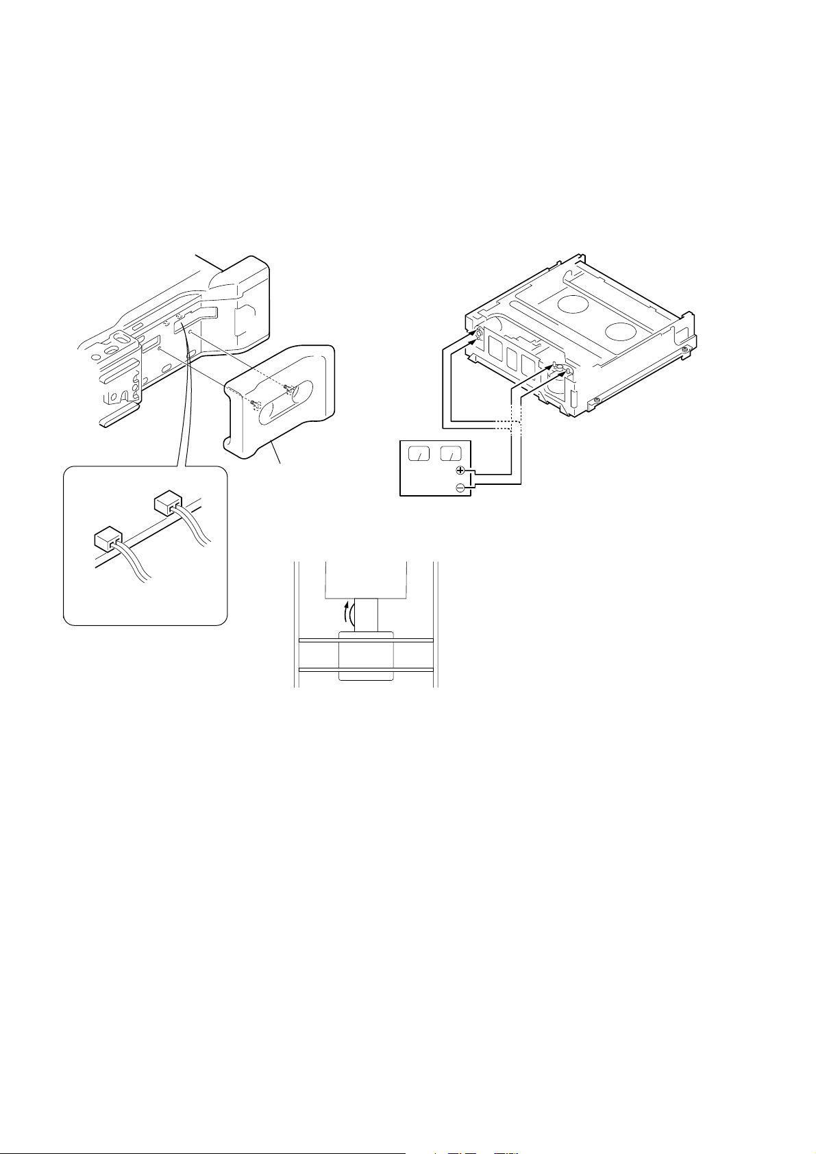
1. TO TAKE OUT A CASSETTE WHEN NOT EJECT (FORCE EJECT)
1 Refer to 2-6. to remove the cabinet (L) assembly.
2 Remove the shoulder pad.
3 Remove the CN4300 (2P) of VI-156 board.
4 Remove the CN501 (2P) of VI-156 board.
5 Supply +4.5V from the DC power supply to the cam motor and unload the tape guide.
6 Rotate the idler gear by your finger to the clockwise and remove the tape slack.
7 Supply +4.5V from the DC power supply to the FL motor (Cassette motor) and unload the cassette.
7
Unload the
cassette.
FL motor
5
Unload the tape guide.
Cam motor
2
Remove the
CN4300 2P
CN501 2P
3
Disconnect CN4300
4
Disconnect CN501
shoulder pad.
6
Remove the idler gear and
remove the tape slack.
DC power supply (4.5Vdc)
What to do when a user forgets a password
This camcorder has the forced log insertion function. A passw ord is inputted, and this function is set up. When this function was set up, this
camcorder doesn’t move if the memory stick which memorize a correct logo isn’t inserted. To release the forced logo function, the correct
password must be input.
This password is memorized in the IC1105 (EEPROM) on VI-156 board. Therefore, when a user forgets the password, replace the IC1105.
This IC1105 memorizes the HRS METER data (Hour meter data: page A, address 00 to 13), too. Therefore, replace the IC1105 in the
following order to copy the HRS METER data.
Replacing procedure:
1) Note down the data of page A, address 00 to 13.
2) Replace IC1105 (EEPROM) on VI-156 board.
3) To page A, address 00 to 13, input the data noted down.
(Refer to “HRS METER (Hours meter)” of “5-4. SERVICE MODE”)
— 8 —

SELF-DIAGNOSIS FUNCTION
1. SELF-DIAGNOSIS FUNCTION
When problems occur while the unit is operating, the self-diagnosis
function starts working, and displays on the viewfinder or LCD
screen what to do. This function consists of two display; selfdiagnosis display and service mode display .
Details of the self-diagnosis functions are provided in the Instruction
manual.
Viewfinder or LCD screen
C : 3 1 : 1 1
Repaired by:
C : Corrected by customer
H : Corrected by dealer
E : Corrected by service
engineer
Blinks at 3.2Hz
3 1C
Block
Indicates the appropriate
step to be taken.
E.g.
31 ....Reload the tape.
32 ....Tur n o n power again.
1 1
2. SELF-DIAGNOSIS DISPLAY
When problems occur while the unit is operating, the counter of the
viewfinder or LCD screen consists of an alphabet and 4-digit
numbers, which blinks at 3.2 Hz. This 5-character display indicates
the “repaired by:”, “block” in which the problem occurred, and
“detailed code” of the problem.
Detailed Code
Refer to page 10.
Self-diagnosis Code Table.
3. SERVICE MODE DISPLAY
The service mode display shows up to six self-diagnosis codes shown in the past.
3-1. Display Method
While pressing the “STOP” key , set the PO WER switch from OFF to ON, and continue pressing the “ST OP” key for 5 seconds continuousl y .
The service mode will be displayed, and the counter will show the backup No. and the 5-character self-diagnosis codes.
Viewfinder or LCD screen
[3] C : 3 1 : 1 1
Lights up
[3]
Backup No.
Order of previous errors
3-2. Switching of Backup No.
By rotating the control dial, past self-diagnosis codes will be shown in order. The backup No. in the [] indicates the order in which the
problem occurred. (If the number of problems which occurred is less than 6, only the number of problems which occurred will be shown.)
[1] : Occurred first time [4] : Occurred fourth time
[2] : Occurred second time [5] : Occurred fifth time
[3] : Occurred third time [6] : Occurred the last time
C : 3 1 : 1 1
Control dial
Self-diagnosis Codes
3-3. End of Display
Turning OFF the power supply will end the service mode display.
Note: The “self-diagnosis display” data will be backed up by the coin-type lithium battery (BT501) of the cabinet (R) assembly (SW-343 board). When
the cabinet (R) assembly is removed, the “self-diagnosis display” data will be lost by initialization.
— 9 —

4. SELF-DIAGNOSIS CODE TABLE
Self-diagnosis Code
Repaired by:
C
C
C
C
C
C
C
C
C
C
C
C
C
C
C
C
C
C
C
C
C
C
E
E
E
E
Block
Function
21
22
31
31
31
31
31
31
31
31
31
31
31
31
32
32
32
32
32
32
32
32
61
61
62
62
Detailed
Code
00
00
10
11
20
21
22
23
24
30
40
42
10
11
20
21
22
23
24
30
40
42
00
10
00
01
Symptom/State
Condensation.
Video head is dirty.
LOAD direction. Loading does not
complete within specified time
UNLOAD direction. Loading does not
complete within specified time
T reel side tape slacking when unloading
Winding S reel fault when counting the
rest of tape.
T reel fault.
S reel fault.
T reel fault.
FG fault when starting capstan.
FG fault when starting drum.
FG fault during normal drum operations.
LOAD direction loading motor time-
out.
UNLOAD direction loading motor
time-out.
T reel side tape slacking when
unloading.
Winding S reel fault when counting the
rest of tape.
T reel fault.
S reel fault.
T reel fault.
FG fault when starting capstan.
FG fault when starting drum
FG fault during normal drum
operations
Difficult to adjust focus
(Cannot initialize focus.)
Zoom operations fault
(Cannot initialize zoom lens.)
Steadyshot function does not work well.
(With pitch angular velocity sensor output
stopped.)
Steadyshot function does not work well.
(With yaw angular v elocity sensor output
stopped.)
Correction
Remove the cassette, and insert it again after one hour.
Clean with the optional cleaning cassette.
Load the tape again, and perform operations from the beginning.
Load the tape again, and perform operations from the beginning.
.
Load the tape again, and perform operations from the beginning.
Load the tape again, and perform operations from the beginning.
Load the tape again, and perform operations from the beginning.
Load the tape again, and perform operations from the beginning.
Load the tape again, and perform operations from the beginning.
Load the tape again, and perform operations from the beginning.
Load the tape again, and perform operations from the beginning.
Load the tape again, and perform operations from the beginning.
Remove the battery or power cable, connect, and perform
operations from the beginning.
Remove the battery or power cable, connect, and perform
operations from the beginning.
Remove the battery or power cable, connect, and perform
operations from the beginning.
Remove the battery or power cable, connect, and perform
operations from the beginning.
Remove the battery or power cable, connect, and perform
operations from the beginning.
Remove the battery or power cable, connect, and perform
operations from the beginning.
Remove the battery or power cable, connect, and perform
operations from the beginning.
Remove the battery or power cable, connect, and perform
operations from the beginning.
Remove the battery or power cable, connect, and perform
operations from the beginning.
Remove the battery or power cable, connect, and perform
operations from the beginning.
Inspect the lens block focus reset sensor (Pin wg of CN001 on VI-
156 board) when focusing is performed when the focusing is rotated
in the focus manual mode, and the focus motor drive circuit (IC140
of VI-156 board) when the focusing is not performed.
Inspect the lens block zoom reset sensor (
156 board
operated and the zoom motor drive circuit (IC140 of VI-156 board)
when zooming is not performed.
Inspect pitch angular velocity sensor (SE601 of SE-116 board)
peripheral circuits.
Inspect yaw angular velocity sensor (SE600 of SE-116 board)
peripheral circuits.
) when zooming is performed when the zoom lever is
Pin ws of CN001 on VI-
— 10 —
SECTION 1
GENERAL
DSR-250/250P
This section is extracted from
instruction manual. (DSR-250P)
1-1
1-2
1-3
1-4
1-5
1-6
1-7
1-8
1-9
1-10
1-11
1-12
1-13
1-14
1-15
1-16
1-17
1-18
1-19
1-20
 Loading...