

Sony DSR-1800, DSR-1800P User Manual

Digital
Videocassette
Recorder
3-204-675-61(1)
Operating Instructions
Before operating the unit, please read this manual
thoroughly and retain it for future reference.
Note
The supplied CD-ROM includes Operating Instructions
for the DSR-series Digital Video Cassette Recorder or Player
(English, Japanese, French, German, Italian and Spanish
(DSR-1500A only) versions).
For more details, see “Using the CD-ROM Manual” on page 12.
DSR-1800/1800P
© 2000 Sony Corporation

Owner’s Record
The model and serial num b ers are located at the rear.
Record these numbers in the spaces provided below. Refer
to them whenever you ca ll upon yo ur So ny de aler
regarding this product.
This symbol is intended to alert the user to
the presence of important operating and
maintenance (servicing) instructions in
the literature accompanying the
appliance.
Model No.
Serial No.
WARNING
To prevent fire or shock hazard, do not
expose the unit to rain or moisture.
To avoid electrical shock, do not open the
cabinet. Refer servicing to qualified
personnel only.
THIS APPARATUS MUST BE EARTHED.
CAUTION
The apparatus shall not be exposed to d ripping or
splashing and no objects filled with liquid, such as vases,
shall be placed on the apparatus.
The unit is not disconnected from the A C power source
(mains) as long as it is connected to the wall outlet, even if
the unit itself has been turned off.
WARNING: THIS WA R N ING IS APPLICA BLE FOR
USA ONLY.
Using this unit at a voltage other than 120 V ma y require
the use of a different line cord or attachment p lug, or both.
To reduce the risk of fire or electric sho ck, refer servicing
to qualified service personnel.
For customers in the US A (DSR -1800 on ly)
This equipment has b een tested and fo und to c omp ly with
the limits for a Class A digital device, pursuant to P art 15
of the FCC Rules. These limits are designed to provide
reasonable protection against harmful interference whe n
the equipment is operated in a com m e rcial environment.
This equipment generates, uses, and can ra diate radio
frequency energy and, if not installed and used in
accordance with the instruction manual, may cause
harmful interference to radio comm u nication s. Op eration
of this equipment in a residential area is likely to cause
harmful interference in which case the user will be
required to correct the interference at his own expense.
You are cautioned that any chang es or m odifications not
expressly approved in this manual could void yo ur
authority to operate this equipment.
The shielded interface cable recomm e nded in this m anua l
must be used w ith this equipment in o rder to co mply w ith
the limits for a digital device pursuant to Subpart B of Part
15 of FCC Rules.
Important Safety Instructions
• Read these instructions.
• Keep these instructions.
• Heed all warnings.
• Follow all instructions.
• Do not use this apparatus near water.
• Clean only with dry cloth.
• Do not block any ventilation openings.
This symbol is intended to alert the user to
the presence of uninsulated “dangerous
voltage” within the product’s enclosure
that may be of sufficient mag nitude to
constitute a risk of electric shock to
persons.
2
Install in accordance with the man ufacturer’s
instructions.
• Do not install near any heat sources such as radiators,
heat registers, stoves, or other apparatus (including
amplifiers) that produce heat.

• Do not defeat the sa fety purpose of the po larized or
grounding-type plug. A polarized plug has two blade s
with one wider than the other. A grounding-type p lug
has two blades and a third grounding
prong. The wide blade or the third prong
are provided for your safety. If the
provided plug dose not fit into your outlet,
consult an electrician for replacement of
the obsolete outlet.
• Protect the power cord from being walked on or pinc hed
particularly at plugs, convenience receptacles, and the
point where they exit from the apparatus.
• Only use attachm ents/accessories spe cified by the
manufacturer.
• Use only w ith the cart, stand, tripod, bracket, or table
specified by the manufacturer, or sold w ith the
apparatus.
When a cart is used, use caution w h en moving the cart/
appa r a t u s combinati o n to avoid injury f rom tip - over.
• Unplug this apparatus d uring lightning storms or when
unused for long periods of time.
• Refer all servicing to qualified service personnel.
Servicing is required when the apparatus ha s been
damaged in any way, such as power-supply cord or plug
is damaged, liquid has been spilled or objects have fallen
into the apparatus, the apparatus has been exposed to
rain or moisture, does not operate normally, or has been
dropped.
Voor de Klanten in Nederlan d
• Dit apparaat bevat een vast ing ebouwd e batterij die niet
vervangen hoeft te word en tijdens de levensduur van het
apparaat.
• Raadpleeg uw leve rancier indien d e batterij toch
vervangen moet wo rden .
• De batterij mag alleen v ervang en worden door
vakbekwaam serviceperso neel.
• Gooi de batterij niet weg m a ar lever dez e in als klein
chemisch afval (KCA).
• Lever het apparaat aan het einde van de leve nsduu r in
voor recycling, de batterij zal dan op correcte wijze
verwerkt worden.
Caution
Television programs, films, video tapes and other
materials may be copyrighted.
Unauthorized recording of such material may be contrary
to the provisions of the copyright laws.
For customers in E urope (DS R-1800 P o nly)
This product with the CE marking com p lies with both the
EMC Directive (89 /336/E E C ) and the Low Voltage
Directive (73/23/EEC) issued by the C ommission of the
European Com munity.
Compliance with these directives implies conformity to
the following European standards:
• EN6006 5: Produ ct Safety
• EN5510 3-1: Electromagnetic Interference (Emission)
• EN5510 3-2: Electromagnetic Susceptibility (Immunity)
This product is intended for use in the following
Electromagnetic Environment(s):
E1 (residential), E2 (commercial and light industrial), E3
(urban outdoors) and E4 (controlled EMC environm ent,
ex. TV studio).
3

AVERTISSEMENT
Afin d’éviter tout risque d’incendie ou d’électrocution, ne
pas exposer l’appareil à la pluie ou à l’humidité.
Afin d’écarter tout risque d’électrocution, garder le coffret
fermé. N e confier l’entretien de l’appareil qu’à un
personnel qualifié.
CET APPAREIL DOIT ÊTRE RELIÉ À LA TERRE.
Attention
Eviter d’exposer l’appareil à un égouttem ent ou à des
éclaboussures et ne placer aucun objet rempli de liquide,
comme un v ase, sur l’app areil.
Cet appareil n’est pas déconnecté de la source
d’alimentation secteur tant qu ’il est raccordé à la prise
murale, même si l’appareil lui-même a été mis hors
tension.
Des programm e s de télévision, films, bandes vidéo et
autres peuvent être protégés pa r des droits d’auteur.
L’enregistreme nt non autorisé de tels matériaux risque de
constituer une violation de ces droits d’auteur.
Pour les clients européens
(DSR-1800P seulement)
Ce produit portant la marque CE est conforme à la fo is à la
Directive sur la compatibilité électromagnétique (EMC )
(89/336/CEE) et à la Directive sur les b asses tensions
(73/23/CEE) ém ises par la C o m mission de la
Communauté européenne.
La conformité à ces directives implique la conformité aux
normes européennes suivantes:
• EN6006 5: Sécurité des produits
• EN5510 3-1: Interférences électromagnétiques
(émission)
• EN5510 3-2: Sen sibilité électromagn étique (immunité)
Ce produit est prévu pour être utilisé dans les
environnements électromag nétiques suivants:
E1 (résidentie l) , E 2 ( c ommercial et industri e légère),
E3 (urbain extérieur) et E4 (environnem ent EM C contrôlé
ex. stud i o d e télévision).
VORSICHT
Um Feuerg ef ahr und die Gefahr eines elektrischen
Schlages zu vermeiden, darf das Gerät weder Reg en noch
Feuchtigkeit ausgesetzt werden .
Um einen elektrischen Sc hlag zu vermeiden, darf das
Gehäuse nicht geöffnet werden. Überlassen Sie
Wartungsarbeiten stets nur qualifiziertem Fachpersonal.
DIESES GERÄT MUSS GEERDET WE RD E N .
Achtung
Das Gerät ist nicht tropf- und spritzwassersicher, daher
dürfen keine mit Flüssigkeiten gefüllten Gegenständ e,
z. B. Vasen, darauf abgestellt werden.
Solange das Netzkabel an eine N etzsteckdose
angeschlossen ist, bleibt das Gerät auch im
ausgeschalteten Zustand mit dem Stromnetz verbunden.
Für Kunde n in E u ro pa (N u r D S R -1 800 P )
Dieses Produkt besitzt die CE-Kennzeichnung und erfüllt
sowohl die EMV-Direktive (89/336/EEC) als auch die
Direktive Niederspannung (73/23/EEC) der
EG-Komm ission.
Die Erfüllung dieser Direktiven bedeutet Konformität für
die folgenden Europäischen Normen:
• EN6006 5: Produ ktsicherheit
• EN5510 3-1: Elek tromag netische Interferenz (Emission)
• EN5510 3-2: Elek tromag netische E mpfindlichkeit
(Immunität)
Dieses Produkt ist für den Einsatz un ter folgenden
elektromagnetischen Bedingungen ausge legt:
E1 (Wohnbe reich), E2 (kom merzieller und in
beschränktem Maße industrieller Bereich), E3
(Stadtbereich im Freien) und E4 (kontrollierter
EMV-Bereich , z.B. Fernsehstudio).
4

ATTENZIONE
1. Für Ihren privat genutzten Videoreco der muß eine
Fernseh-Rundfunk-Gene hmigung beantragt
werden, sofern nicht bereits eine Gene hmigung für
ein Fernsehgerät desselben Haushaltes vorliegt. Im
geschäftlichen Bereich ist jeder einzelne
Videorecorder anmelde- und gebührenpflichtig.
(Auskunft ggf. bei der GEZ oder den
Rundfunkanstalten.)
2. Im privaten Bereich ist die Aufzeichnung von
urheberrechtlich geschützten Werken auf Bildund Tonträger gestattet. Die entsprechende n
Urheber-Vergütungen sind im Kaufpreis d es
Gerätes enthalten. Öffentliche Wiedergabe oder
Verbreitung von mitgeschnittenen
Fernsehsendungen ist ohne Erlaub nis nicht
zulässig, verpflichtet zu Schadenersatz und ist
gegebenenfalls strafbar.
3. Im Rahme n der R ege lung de s §47 des
Urheberrechtsgesetzes sind Aufzeichnu ngen von
Schulfernsehprogramm e n gestattet. M itschnitte
von Schulfunksendungen dürfen jedoch nur für
den Unterricht verwendet we rden un d sind
spätestens am E nde d es laufend en Sc huljahres zu
löschen.
Per evitare il pericolo di incendi o scosse e lettriche, non
esporre l’apparecchio alla pioggia o all’um idità.
Per evitare scosse elettriche, non aprire l’ap parecchio. Per
le riparazioni, rivolgersi solo a personale qualif icato.
QUESTO APPARECCHIO DEVE ESSERE MESSO A
TERRA.
Attenzione
L’apparec chio no n dev e essere esp osto a gocciolamenti o
spruzzi. Non collocare sull’apparecchio o ggetti contenenti
liquidi, come ad esempio vasi di fiori.
L’apparec chio no n è scollegato dalla fonte di
alimentazione CA (corren te di rete) fintanto che è
collegato ad una presa di corrente, anche se l’apparecch io
stesso è stato spento.
Programmi televisivi, film, videonastri e altro materiale
possono essere tutelati dai diritti d’autore.
Registrazioni non autorizzate di tali materiali possono
infrangere la legge sui diritti d’autore.
Per i clienti in Euro p a (DS R -1 800 P so ltan to )
Questo prodotto recante il marchio C E è co nforme sia alla
direttiva sulla compatibilità elettromagnetica (EMC)
(89/336/CEE) che alla direttiva sulle basse tensioni
(73/23/CEE) emesse dalla Comm issione della Comunità
Europea.
La conformità a queste direttive implica la conformità alle
seguenti normative europee:
• EN6006 5: Sicurezz a dei prod otti
• EN5510 3-1: Interferenza e lettromagnetica (Emissione)
• EN5510 3-2: Sen sibilità ai disturbi elettromagnetici
(Immunità)
Questo prodotto è destinato all’uso nei seguenti ambienti
elettromagnetici:
E1 (residenziali), E2 (comm erciali e industriali leggeri),
E3 (esterni urbani) e E4 (ambienti EMC controllati, ad
esempio studi televisivi).
5

6

Table of Contents
Chapter 1 Overview
Features........................................................................9
DVCAM Format .............................................................9
A Wealth of Interfaces..................................................10
Facilities for High-Efficiency Editing...........................10
Other Features...............................................................11
Optional Accessories.....................................................11
Using the CD-ROM Manual.......................................12
CD-ROM System Requirements...................................12
Preparations...................................................................12
To Read the CD-ROM Manual.....................................12
Location and Function of Parts................................13
Front Panel....................................................................13
Rear Panel .....................................................................21
Chapter 2 Recording and Playback
Usable Cassettes.......................................................27
Inserting and Ejecting Cassettes ...................................29
Recording...................................................................31
Settings for Recording ..................................................31
Recording Procedure.....................................................34
Playback.....................................................................37
Settings for Playback ....................................................37
Playback Procedure.......................................................38
Repeat Playback—Automatic Cyclical Playback .........40
Setting Points A and B for Repeat Playback.................40
Cuing Up to Any Desired Position Set as Point A or B45
Chapter 3 Convenient Functions for Editing Operation
Setting the Time Data................................................47
Displaying Time Data and Operation Mode Indications ..
47
Using the Internal Time Code Generator...................... 49
Synchronizing Internal and External Time Codes........51
Rerecording the Time Code—TC Insert Function........ 51
High-Speed and Low-Speed Search—Quickly and
Accurately Determining Editing Points ............54
Search Operations via External Equipment ..................54
Search Operations on This Unit....................................55
7

Digitally Dubbing Signals in DVCAM Format..........56
Chapter 4 Menu Settings
Menu Organization....................................................59
Menu Contents...........................................................62
Setup Menu...................................................................62
Auto Mode (AUTO FUNCTION) Execution Menu.....75
Changing Menu Settings ..........................................76
Buttons Used to Change Settings..................................76
Changing the Settings of Basic Items...........................76
Displaying Enhanced Items ..........................................78
Changing the Settings of Enhanced Items ....................78
Returning Menu Settings to Their Factory Default
Settings ................................................................79
Displaying Supplementary Status Information.......80
Chapter 5 Connections and Settings
Connections for a Digital Non-Linear Editing System
83
Connections for a Cut Editing System....................85
Connections for an A/B Roll Editing System..........86
Connections for SDTI (QSDI) Dubbing....................92
Connections for Analog Recording.........................93
Adjusting the Sync and Subcarrier Phases............94
Chapter 6 Maintenance and Troubleshooting
Maintenance...............................................................97
Condensation.................................................................97
Regular Checks .............................................................97
Head Cleaning...............................................................99
Troubleshooting......................................................100
Error Messages............................................................ 102
Alarm Messages..........................................................102
Appendixes
Precautions..............................................................105
Specifications..........................................................106
ClipLink Guide.........................................................110
What Is ClipLink?.......................................................110
Example System Configuration and Operation Flow. 111
Data Generated When Shooting..................................112
Glossary...................................................................115
Index.........................................................................117
8

Overview
Features
The DSR-1800/1800 P is a 1/4-inch digital video cassette
recorder using the DVCAM digital recording format. It
achieves stable, superb picture quality by digitally
processing video signals separated into color difference
signals and luminance signals (component method).
The unit is equipped with a v ariety of functions needed for
videocassette recorders and players used in professional
digital video editing systems. It supports the ClipLink
function developed by Sony Corporation fo r highly
efficient video editing. When connected to a Son y
EditStation
linear editing system*.
The unit is also equipped with a full-fledged analog
interface to support hybrid systems that combine
conventional analog equipment with digital equipment.
* Non-linear editing: This is an editing method that use s video and audio
signals di gitally encode d and re corde d on a h ard disk as di gital da ta. When
compared with conventional (linear) editing methods, non-linear editing
offers vastly improve d efficiency in editing operations, for example, by
eliminating tape transport time.
The main features of the unit are described in the
following.
TM
, the unit serves as part of a powerful non-
TM
Chapter
Because the recording is digital, multi-generation du bbing
can be performed w ith virtually no deterioration of quality.
Wide track pitch
The recording track pitch is 15 µm, fully 50 percent wider
than the 10-µm track pitch of the DV form at. Thanks to this
feature, the DVCA M format sufficiently meets the
reliability and precision requirements of professional
editing.
High-quality PCM digital audio
PCM recording m ak es for a wide dynamic range and a
high signal-to-noise ratio, thereby enhancing sound
quality.
There are two recording modes: 2-chann el mode (4 8-kHz
sampling and 16-bit quantization), which o ffers sound
quality equivalent to the DAT (D igital Au dio Ta pe)
format, or 4-channel mode (32-kHz sampling and 12-bit
quantization).
Playback compatibility with DV and
DVCPRO formats
A DV cassette recorded on a D V form at VCR as well as a
DVCPR O (25M) format recorde d cassette can be p layed
back on this unit.
1
DVCAM Format
DVCAM is based on the consumer DV format, which uses
the 4:1:1 component digital format, and provides a
digital recording format for professional use.
High picture quality, high stability
Video signals are separated into color difference signals
and luminance signals, which a re encoded and compressed
to one-fifth size before being recorded to ensure stable and
superb picture quality.
1
/4-inch
Note
When playing back a tape recorded in DVCPRO (25M)
format, the SDTI and i.LIN K outpu ts (see “D igital
interfaces” on page 10) of this unit are muted.
Furthermore, it is not possible to play back the cue-au dio
track of the tape.
Features
9

Support for three cassette sizes
There are two sizes of D VCAM ca ssette: standard and
mini. You can use either size with this unit.
The unit also accepts L and M sizes of DV C PRO cassette.
• When a cassette is inserted, the reel mechanism of the
unit automatically adjusts to the size of the inserted
cassette.
• The capacity of a standard casse tte is 184 minutes of
Chapter 1 Overview
recording/playback, and that of a mini cassette is 40
minutes.
A Wealth of Interfaces
Digital interfaces
The following optional digital interfaces are available for
use with the unit.
SDTI (QSD I)* (op tional D S B K-1802 SDTI (Q S DI)
Input/Output Board): When the unit is fitted with the
optional DSBK -18 02 b oard, S D T I (Q S D I)-format
video, audio and time code signals can be transferred
between the unit and the Sony E ditStation at norm al
speed. When this unit is connected to another
DVCAM VCR, it is possible to copy compressed
signals between the two V CRs.
SDI (serial digital interface)/AES/EBU (op tiona l
DSBK-1801 SD I/AE S /EBU Input/Output Board):
When the unit is fitted with the optional DS B K-1801
board, it can input and output D1 (componen t) format
digital video and audio signals and also AE S/EB Uformat digital audio signals.
i.LINK (DV)** (o ptional D S B K-1803 i.LINK/D V
Input/Output Board): When the unit is fitted with the
optional DSBK-1803 board (i.LINK co mpatible), it
can input and output digital video and audio signals in
DV format.
* SDTI is the name of a standard inter f ace established as SMPTE 305M.
QSDI is a typ e of S DTI . This unit uses SDTI to t ran smit DV da ta , and th e
input/output connectors are labeled “SDTI (QSDI).”
** i.LINK and are trademarks and indi cate th at this pro duct is in agreem ent
with IEEE1394-1995 s pecifications and their revisions.
Analog interfaces
The unit also comes with analog interfaces enabling it to be
connected to analog video and audio equipm en t.
Analog video: These interfaces include a component
interface, composite interface, and S-video interface.
Analog audio: Four channels each of input and output are
provided. It is also possible to connect a microphone to
the unit.
Facilities for High-Efficiency Editing
The unit provides an abundance of functions that enhance
editing efficiency and precision.
Cross-fade editing
For audio editing, you can select from cut-in editing, fadein/fade-out editing, and cross-fade editing.
Support for ClipLink function
In response to comman ds sent from the EditStation, index
pictures recorded on tape or ClipLink log data recorded in
the cassette memory can be transferred to the E ditStation.
The EditStation operator can then efficiently use these
pictures and data in a preliminary editing session.
For an overview of the ClipLink function, see the appendix
“ClipLink Gu ide ” (page 110).
Internal time code generator and reader
An internal time code generator and rea der enab les time
code compliant with S MPT E (for DS R-1800)/EB U (D SR1800P) format to be recorded and play ed back. This allows
editing to single frame precision.
Outputting or inputting time code (L T C) to or from an
external device is also possible using the TIM E CO DE IN /
OUT connectors.
The unit is also compatible with V ITC.
Remote control
The unit can be operated by remote control from an editing
control unit that supports the RS-422A interface or from an
optional SIRCS*-compatible rem ote con trol unit such as
the DSRM-10.
* SIRCS (Sony Integrated Remote Control System): A command protocol
to remote control S on y prof essional videocas sette recorders/pla y ers.
Playback control using search dial
The search dial on the front pane l of the unit allows you to
carry out playback operation in jog or shuttle mode
without requiring an external editing control unit or remote
control unit to be connected to the unit.
High-speed search function
The unit has a picture search function that allows yo u to
view color picture at playback speeds up to 85 tim es
normal speed in forward and rev erse directions.
When remote-con trolling this unit in shuttle mode from an
editing control unit or a remote control unit, you can search
at any speed in the range 0 (still) to 60 times normal speed
in both directions. You can also search frame-by-frame in
jog mode.
10
Features

At search speeds up to 10 times no rmal speed in both
directions, you can also hear playback audio.
Digital slow-motion playback
Using the frame me mory function, the unit can show
noise-free slow-motion playback at speeds ranging from 0
1
/2 times normal speed in both d irections.
to
Compatible with wide-screen aspect ratio
(16:9)
The unit can record and play back aspe ct ratio information.
When video accompanied by wide-screen aspect ratio
information is recorded or played back, the unit can output
the video signal also containing the aspect ratio
information.
Digital jog sound function
When searching at speeds in the ran g e + 1 to +1/30 or
1
/30 to −1* times norm a l speed, the digital jog sound
−
function is enabled. The audio signal is saved in temporary
memory, and replayed ac cording to the search speed. This
allows searching on the sound track.
* Th e positive direction refers to forward movement of the tape, and the
negative direction to reverse movement.
Video process control
For analog video output and SDI-format v ideo output, you
can adjust the video output level, chroma signal output
level, setup level (for DSR-1800), black level (for D SR1800P), and chroma phase.
Other Features
Menu system for functionality and
operation settings
The unit provides a menu system to make its various
functions easier to use and set up its operation conditions.
Rack mountable
When you use the op tional RM M-130 Rack M oun t K it,
you can mount this u nit onto an EIA-standard 19-inch rack
(height = 4 units).
Optional Accessories
DSBK-1801 SDI/AES/EBU Input/Output
Board
When installed in the unit, this optional board enables
digital video and audio signals in the D1 form a t and also
AES/EBU -form a t digital audio signals to be transferred
between this unit and digital Betacam V CRs or other
digital equipment.
DSBK-1802 SDTI (QSDI) Input/Output
Board
This interface allows video, audio and time code signals in
SDTI (QSDI) format to be transferred at norm al speed
between this unit and the Sony EditStation. When this unit
is connected to another DV C A M VCR , it is possible to
copy compressed signals betwee n the tw o VCRs.
Chapter 1 Overview
Superimposition function
Time code values, operation m ode indications, error
messages, and other text data can be superimposed and
output in analog composite video signals.
Easy maintenance functions
Self-diagnostic/alarm fun c tion: T h is function
auto matica l l y detects setu p and c o nnec t io n erro r s ,
operation faults, and other problems. It also displays a
description of the problem, its cause, and the
recommended response on the video monitor screen or
time counter display.
Digital hours meter: The digital hou rs m e ter function s
include four kinds of tally operations for operating
hours, head drum usage hours, tape transport hou rs,
and tape threading/unthreading times. The tally results
can be viewed on the video monitor or the time counter
display.
DSBK-1803 i.LINK/DV Input/Output Board
This board allows you to connec t the unit to other
equipment provided w ith a Sony DV connector to carry
out editing or dubbing of digital video and audio signals.
RMM-130 Rack Mount Kit
This kit can be used to mount the u nit onto an E IA standard 19-inch rack.
Features
11

Using the CD-ROM Manual
The supplied CD-ROM includes O p erating Instructions
for the DSR-series Digital Video Cassette Recorder or
Player (English, Japanese, French, German, Italian and
Spanish (DSR-1500A only) versions).
Chapter 1 Overview
CD-ROM System Requirements
The following are required to acc ess the supp lied CDROM disc.
• Computer: PC with MM X Pentium 166 MHz or faster
CPU, or Macintosh co mputer with PowerPC CPU.
- Installed memory: 32 MB or more
- CD-RO M drive: × 8 or faster
• Monitor: Mon itor supporting resolution of 800 × 60 0 or
higher
When these requirem ents are n ot met, access to the CDROM disc may be slow, or not possible at all.
Preparations
The following software must be installed on your
computer in order to use the O perating In structions
contained in the CD-ROM disc.
• Microsoft Internet Explorer V ersion 4 .0 o r higher, or
Netscape Navigator V ersion 4.0 or high er
• Adobe A croba t Read er Version 4.0 or higher
Select and click the Operating Instructions that you
2
want to read.
A PDF file of the O perating Instructions o pens.
Note
If you lose the CD-RO M disc or become unable to read its
content, for example because of a hardware failure, contact
a Sony service representative.
• MMX and Pentium are registered trademarks of Int el Corporation or its
subsidiaries in the United States and other countries.
• PowerPC is a registered trademark of International Business Machines
Corporation.
• Macintosh is a registered trademark of Apple Computer, Inc.
• Microsoft is a registered trademark of M icrosoft Cor poration in t he United
States and/or other countries.
• Netscape Naviga tor is a registered trademark of Netscape
Communications Corporation in the U.S. and other countries.
• Adobe and Acrobat are registered trademarks of Adobe Systems
Incorporated in the United States and/or other countries.
Note
• If Microsoft Internet Explorer is not installed, it ma y be
downloaded from the following URL:
• http://www.microsoft.com/ie
• If Netscape Navigator is not installed, it may be
downloaded from the following URL:
• http://home.netscape.com/
• If Adobe A crobat Reader is not installed, it may be
downloaded from the following URL:
• http://www.adobe.com/products/acrobat/readstep.html
To Read the CD-ROM Manual
To read the Operating Instructions contained in the C DROM disc, do the following.
Insert the CD-ROM disc in your CD -R OM drive.
1
A cover page appears automatically in your browser.
If it does not appear automatically in the brow ser,
double click the index.htm file on the CD-ROM disc.
Using the CD-ROM Manual
12
Location and Function of Parts
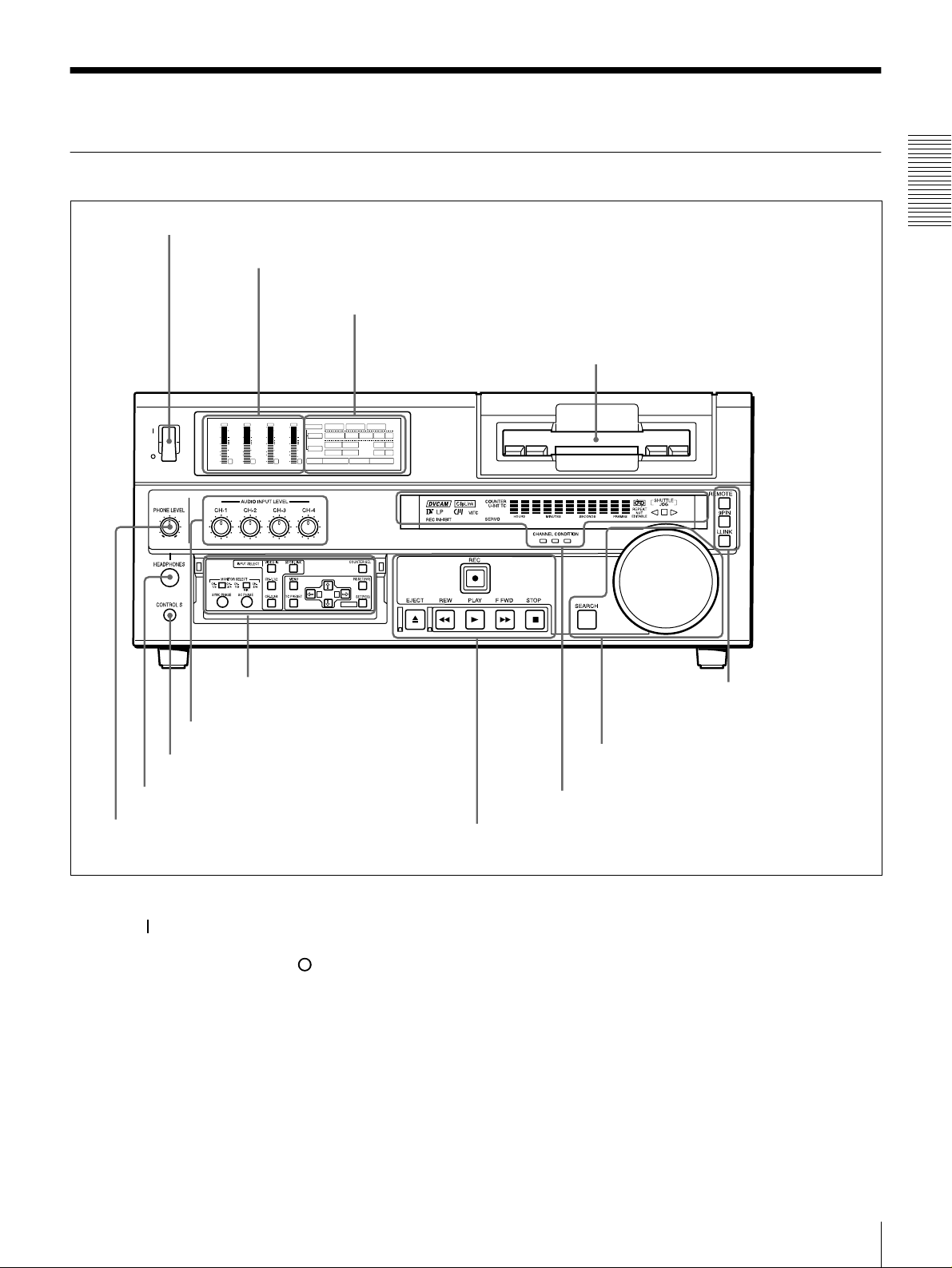
Front Panel
a POWER switch
POWER
OVER
dB
dB
dB
0
0
1
-12
-12
0
-20
-20
-1
-30
-30
-40
-40
-2
-60
-60
1
b Audio level meters
A Input selection/audio mode
display se c t ion
OVER
OVER
OVER
dB
dB
dB
dB
dB
INPUT
0
0
0
0
1
1
-12
0
0
-20
-1
-1
-30
-40
-2
-2
-60
2
3
V:SDTI SDTI i.LINK
0
0
COMPOSITE
Y-R,B
S VIDEO
MARK
AES/EBU
AES/EBU
REC MODE
2CH4CHPB FS
SDI SG
SDI SG
SDI SG
VIDEO
1
-12
CH11/2
0
-20
ANALOG
AUDIO
-1
-30
ANALOG
CH23/4
-40
-2
48k44.1k32k
-60
4
A B
B Menu control panel (inside of
the door)
(see page 15)
(see page 14)
c Cassette compartment
F Remote control setting
section
Chapter 1 Overview
(see page 20)
g AUDIO INPUT LEVEL control knobs
f CONTROL S connector
e HEADPHONES connector
d PHONE LEVEL control knob
a POWER switch
Press the “” side to power the unit on. When the unit is
powered on, the display windo w s in the front pan el lights.
To power the unit off, press the “” side of the switch.
b Audio level meters
These show the audio levels of channels 1 to 4 (recording
levels in recording mode or E-E m ode* and playback level
in playback mode).
* E-E mode: Abbreviation of “Electric-to-Electric mode.” In this mode,
video and audio signals input to the VCR are output after passing through
internal electric circuits, but not through magnetic conversion circuits such
as heads and tapes. This can be used to check input signals and for
adjusting input signal levels.
E Search control section
(see page 19)
D Display section
C Tape transport control section
(see page 18)
(see page 17)
c Cassette compartm ent
Accepts DVC A M, DV and D V C P R O (25M)
videocassettes.
For details of usable cassettes, see page 27.
d PHONE LE V EL control knob
Controls the volume of the headph ones c onnec ted to the
HEADPHONES connector.
Location and Function of Parts
13
e HEAD PHONE S con n ecto r (stereo p hone jack)
Connect stereo headphones for headpho ne monitoring
during recording or playback.
The audio signal you w ant to monitor can be selected with
the MONIT O R SELEC T switches o n the m enu control
panel.
f CONTR OL S connector (stere o minijack)
Connect a SIRCS -com p atible rem o te co ntrol unit such as
Chapter 1 Overview
the DSRM-10.
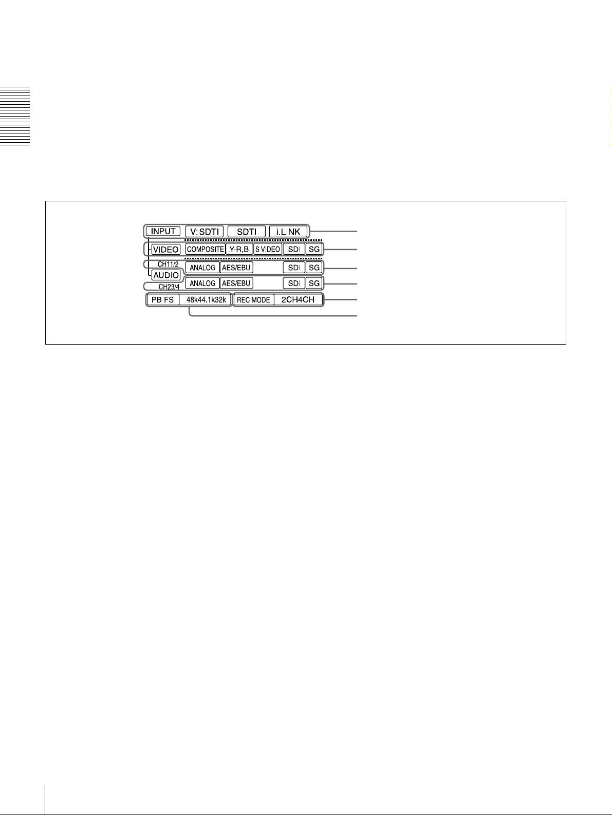
Input selection/audio mode display section
A
g AUDIO INPUT LEVEL control knobs
When recording, you can use these knobs to set audio input
levels for CH-1 (channel 1), CH-2, CH-3 and CH-4,
respectively.
You can mak e these k nobs ino perative w ith the RE C
LEVEL menu item (see page 70).
a INPUT display
b VIDEO display
c AUDIO CH1 1/2 display
d AUDIO CH2 3/4 display
e REC MODE display
f PB FS display
a INPUT d isplay
Indicates the input signal selected with the SDT I/i.LINK
butto n in the I NPUT SELECT sec t ion.
V:SDTI: Digital video signal in SDTI(QSDI) format
SDTI: Digital video and audio signals in SDTI(QSDI)
format
i.LINK: D igital video and aud io signals in i.LINK -
com patible DV f ormat
The SDTI/i.LINK b utton to func tion fully requires the
optional DSBK-1802 and 1803 boards to b e installed. The
signal without the corresponding optional board installed
in the unit can be neither selected nor indicated.
b VIDEO display
Indicates the input video signal selected with the VIDE O
IN button in the INPU T S ELECT section.
COMPOSITE: Composite video signal
Y−R, B: Y, R−Y and B−Y component video signals
S VIDEO: S-video signal
SDI: SDI video signal (optional DS BK-1801 board
required)
SG: Video test signal
c AUDIO CH1 1/2 display
Indicates the input audio signal selected with the CH-1,1/2
butto n in the I NPUT SELECT sec t ion.
ANALOG: Analog audio signal
AES/EBU: Digital audio signal in AES/EB U format
(optional DSBK-1801 board required)
SDI: SDI audio signal (optional DS BK-1801 board
required)
SG: Audio test signal
d AUDIO CH2 3/4 display
Indicates the input audio signal selected with the CH-2,3/4
butto n in th e I NPU T SELEC T sec t ion. The indicatio ns
available are the same as for the AUDIO CH1 1/2 display
described above.
e REC M O DE (audio recording mode) display
Indicates the audio recording mode (2C H or 4CH) selected
with the REC MODE menu item (see page 69).
f PB FS (playback audio sa mpling frequency)
display
Indicates the sampling frequency (48 kHz, 44.1 kHz or 32
kHz) at which audio is recorded on tape.
Location and Function of Parts
14
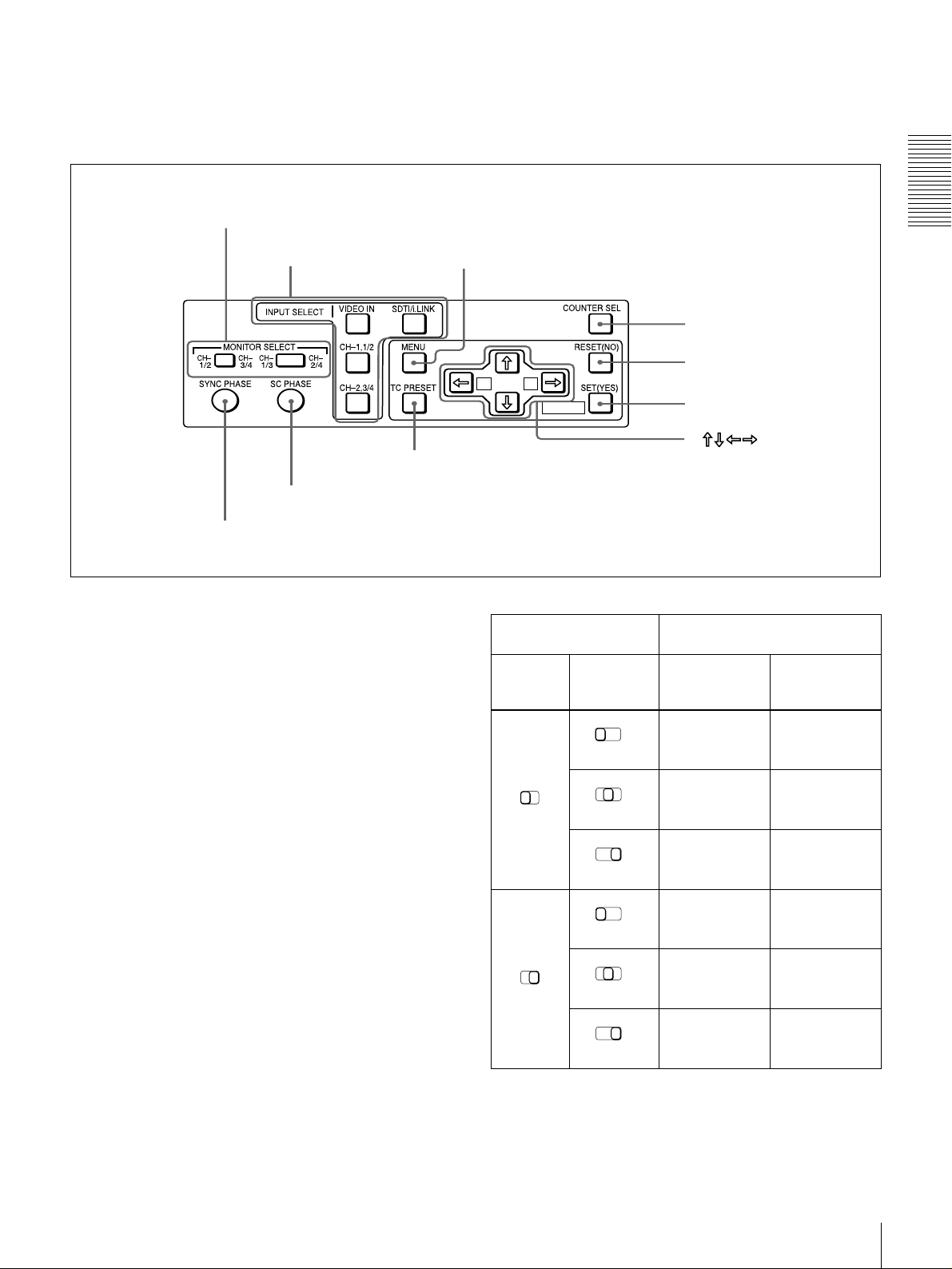
B Menu control panel
The menu control panel is located on the inside of the door
at the lower front of the unit. Pull the top of the door to
open it.
a MONITOR SELECT switches
b INPUT SELECT section
MIX
h TC PRESET button
i SC PHASE contro l
j SYNC PHASE control
a MONITOR SELECT switches
Use these switches to select the channels for audio output
via the AUDIO MONITO R OUT connector o n the rear
panel and the HEADPHONES connector on the front
panel.
Use the left switch to select the basic channel setting, then
use the right switch to select the output format (monaural,
stereo, or mix).
c MENU button
d COUNTER SEL button
e RESET (NO) button
A B
MARK
f SET (YES) button
g
buttons
Switch setting Selected channel and output
format
Left
switch
Right
switch
CH1/3
MIX
HEADPHONES
connector
Channel 1 only
CH2/4
(monaural)
Chapter 1 Overview
AUDIO
MONITOR OUT
connector
Channel 1 only
(monaural)
The following table lists the correspondence of left/right
switch settings and channel/output format selections.
CH1/2
CH1/2
CH-
CH-
1/3
3/4
CH3/4
MIX
CH-
1/3
MIX
CH-
1/3
MIX
CH-
1/3
MIX
CH-
1/3
MIX
Channels 1 and
CH-
2/4
2 (stereo)
Channel 2 only
CH-
2/4
(monaural)
Channel 3 only
CH-
2/4
(monaural)
Channels 3 and
CH-
2/4
4 (stereo)
Channel 4 only
CH-
2/4
(monaural)
Location and Function of Parts
Channels 1 and
2 (mix)
Channel 2 only
(monaural)
Channel 3 only
(monaural)
Channels 3 and
4 (mix)
Channel 4 only
(monaural)
15

b INPUT SELECT section
VIDEO IN button
Each press of this button cycles through the following
input video signal selection options.
• Compo site video signal input to the VIDEO IN
connectors
• Component video signals input to the CO MPONE NT
VIDEO IN connectors
Chapter 1 Overview
• S-video signal input to the S VID EO IN connector
• SDI video sign al input to the SDI IN connector (op tional
DSBK-180 1 boa rd required)
• Video test signal (selected with the IN T VIDEO SG
menu item (see page 68) generated by the internal signal
generator
In the input selection/audio mode display section, the
VIDEO display show s the selection made w ith this button.
CH1,1/2 (audio channel 1 o r 1/2) bu tton
Each press of this button cycles through the following
input audio signal selection options for audio channel 1
(when in 2-channel mode) o r for audio chann els 1 and 2
(when in 4-channel mode).
• Analog audio signal(s) input to the A UDIO IN CH-1
connector (when in 2-channel mode) or AUDIO IN CH-
1 and CH-2 connectors (when in 4-channel mode )
• Digital audio signal in AE S/EB U format input to the
DIGITAL AUDIO (AES/EBU) IN CH-1/2 connector
(optional DSBK-1801 bo ard requ ired)
• SDI audio sign al input to the SDI IN connector (op tional
DSBK-180 1 boa rd required)
• Audio test signal (selected with the IN T AUDIO SG
menu item (see page 71) generated by the internal signal
generator
In the input selection/audio mode display section, the
AUDIO CH1 1/2 display shows the selection made with
this button.
When this is selected, use the CH1,1/2 button and
CH2,3/4 button to select the required input audio signals.
Note
In this case, the phases of the selected audio signals
will be about two frame s ahead of the ph ase of the
digital video signal in SDTI (QSDI) format.
• Digital video and audio signals in SDTI(QSDI) format
input to the SDTI(QSD I) IN connector (optional D SBK 1802 board required)
• Digital video and audio signals in i.LINK-compatible
DV format, input to the DV IN/OUT connector
(optional DSBK-1803 board requ ired)
In the input selection/audio mode display section, the
INPUT display show s the selection ma de with this button.
c MENU button
Press this button to display the menu on the monitor screen
and the time counter display. Press it again to return from
the menu display to the usual display.
On how to use the m en u, see C h apter 4 “Menu Settings.”
d COUNTER SEL (selection) button
Selects the type of time data to be show n in the time
counter display. Each press of this button cycles through
three indicator display options: COUNT ER (CNT: count
value of the time counter), TC (time c ode), and U -B IT
(user bits).
Note
When the RE MOTE bu tton in the rem ote control setting
section is lit, the COUNTE R SEL button do es not operate.
In this case, make the time data selection via the rem ote
equipment that is connected to the R EMOT E connector on
the rear panel.
CH2,3/4 (audio channel 2 o r 3/4) bu tton
Each press of this button cycles through the input audio
signal selection options for audio channel 2 (when in 2channel mode) or for audio chan nels 3 an d 4 (when in 4channel mode). The input au dio signal selection op tions
corresponding to those for the CH1,1/2 button described
above are available.
In the input selection/audio mode display section, the
AUDIO CH2 3/4 display shows the selection made with
this button.
SDTI/i.LINK (SDTI(QSDI) interface/i.LINK selection)
button
Each press of this button cycles through the following
input signal selection options.
• Digital video signal in SDTI(QSDI) form at input to the
SDTI(QSD I) IN connector (optional DSB K-180 2 board
required)
Location and Function of Parts
16
e RESET (N O) button
Pres s this bu t to n to:
• reset menu settings,
• reset the time count (COUNTER) shown in the time
counter display to zero, or
• send a negative respon se to the p rom pts issued by the
unit.
f SET (YES) button
Pres s this bu t to n to:
• save new settings, such as selected m enu items an d time
code settings, to the memory of the unit, or
• send a positive response to the prompts issued by the
unit.
g Arrow (JjKk) button s
Use these buttons to move around the menu items, and also
for setting time code and user bit data.
For details on setting time code and user bit data, see
“Using the Internal Time Code Generator” on page 49.
h TC (time cod e) PRESET b utton
Use this button when setting an initial time code value and
user bit data.
For details on setting time code and user bit data, see
“Using the Internal Time Code Generator” on page 49.
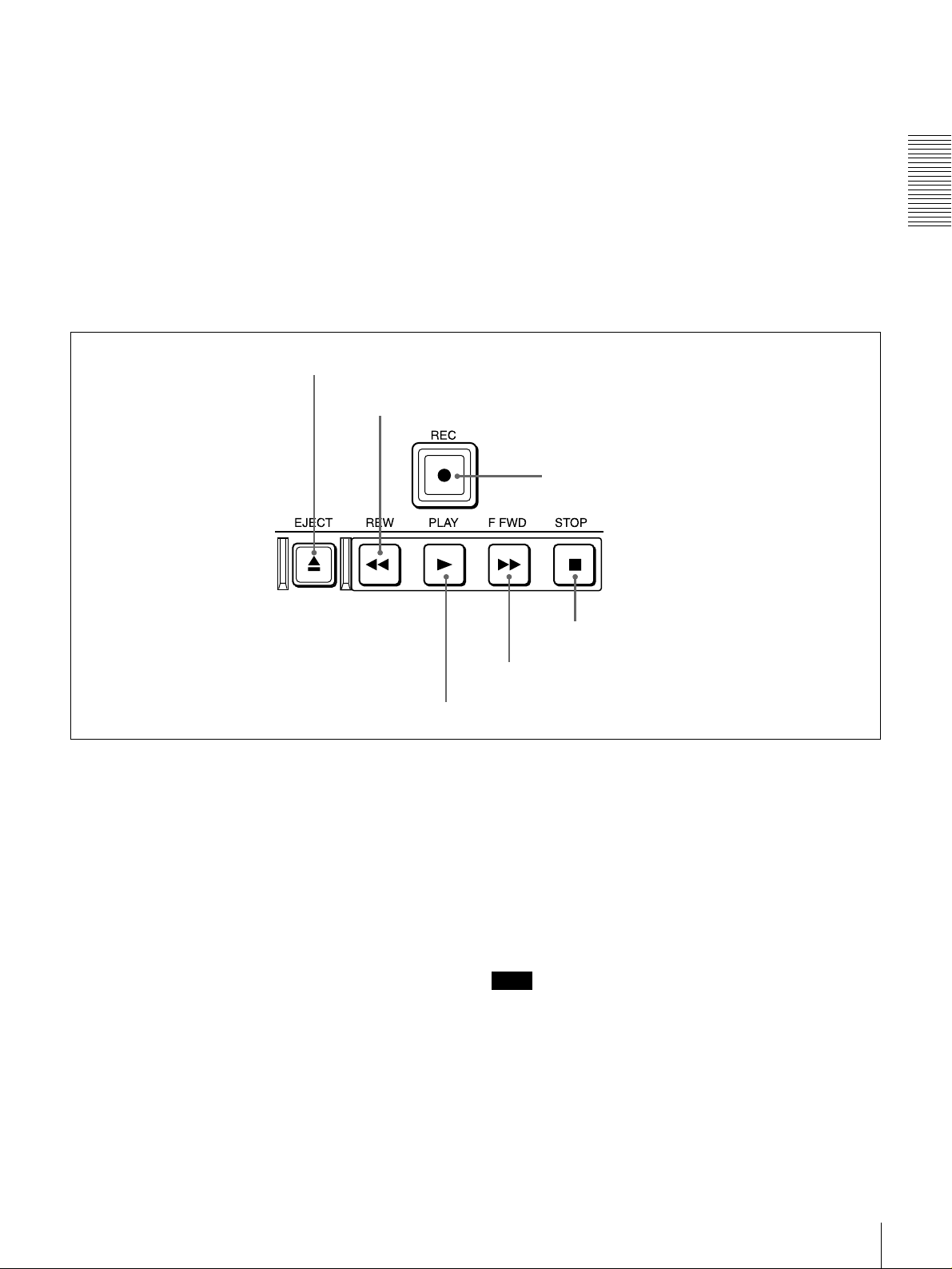
Tape transport control section
C
a EJECT button
b REW button
i SC (subcarrier) PHASE control
Turn this control to accurately adjust the subca rrier phase
of the composite video output signal of the unit w ith
respect to the reference video signal. Use a cross-point
(Phillips) screwdriver to turn it.
j SYNC (synch r onization) PHASE control
Turn this control to accurately adjust the synchronization
phase of the output video signal of the unit with respect to
the reference video signal. Use a cross-point (Phillips)
screwdriver to turn it.
c REC button
Chapter 1 Overview
d PLAY button
a EJECT button
When you press this b utton, it lights and the cassette is
automatically ejected after a few seconds.
b REW (rewind) button
When you press this b utton, it lights and the tape starts
rewinding (maximu m 85 tim es normal speed).
When the F. FWD /REW menu item (see page 63) is set to
PB, you can monitor the playback picture during the
rewind.
c REC (record) bu tton
When you press this button w hile holding down the PLA Y
button, it lights and recording begins.
d PLAY b utton
When you press this button, it lights and p layback be gins.
If you press this button during recording or editing, the
recording or editing operation is stopped and this unit
enters playback mode.
f STOP button
e F FWD button
e F FWD (fast forw ar d ) bu tton
When you p ress this button, it lights and the tape is fast
forwarded (maxim um 85 times norma l speed).
When the F. FWD /REW menu item (see page 63) is set to
PB, you can monitor the p layback picture during the fast
forward.
f STOP button
Press this button to stop the current tape transport
operation.
Note
No tape transport control buttons other than the EJE CT
and STOP buttons will work w hile the REMO TE button in
the remote control setting section is lit. This can be
changed with the LOCAL ENABLE menu item (see page
63).
Location and Function of Parts
17

D Display section
Chapter 1 Overview
a Recording/playback format indicators
b ClipLink indicator
c VITC indicator
d Time data type indicators
e Time counter display
i CHANNEL CONDITION indicators
h SERVO indicator
g Cassette memory indicator
f REC INHIBIT indicator
j REPEAT indicator
a Recording/playback form a t indicators
DVCAM: This lights when a tape recorded in DV C AM
format is played back.
DV: This lights when a tape recorded in consumer D V
format is played back.
LP: This lights when a tape recorded in LP mode is played
back.
When a tape recorded in DVCPRO (25M) form at or any
other format than those mentioned abo ve is played back,
none of the above indicators lights.
k Tape end alarm indicator
l SHUTTLE/JOG indicators
m NOT EDITABLE indicator
Note
A tape recorded in LP m ode c annot b e played back
correctly. When a tape recorded in LP m o de is playe d
back, “DV LP” flashes and audio is muted.
b ClipLink ind icato r
Lights when a cassette is loaded on which ClipLink log
data is s t o r e d in the c assett e mem ory.
For details of ClipLink log data, see the appendix
“ClipLink Gu ide ” (page 110).
Location and Function of Parts
18
c VITC indicator
Lights when VITC is being read or recorded regardless of
the data shown in the time counter display.
d Time data type indicators
One of the three indicators (CO UNTER, U-B IT , and T C )
lights to indicate the type of time data currently shown in
the time counter display.
COUNTER: Count value of the time counter
U-BIT: User bit data
TC: SMPTE time c ode (for DSR-180 0) or EBU tim e code
(for DSR-1800P)
e Time counter display
Indicates the count value of the time counter, time c ode,
VITC, or user bit data depending on the se ttings of the
COUNT ER SEL button on the m enu control panel and the
TC SELECT menu item (see page 66).
Also used to display error messages and setup menu data.
f REC (recording) INHIBIT ind icator
Lights in the following cases:
• The RE C /SAVE switch on the loade d cassette is in the
SAVE position.
• The REC INH IBIT m enu item (see page 6 3) is set to
ON.
l SHUTTLE/JOG indicators
When searching in shuttle mode using the search dial, the
SHUTTLE in dicator ligh t s , and when s e a r c hing in jog
mode using the search dial, the JOG indicator lights. When
the search dial is turned clockwise causing playback to
take place in the forward direction, the G ind ic a to r lig ht s .
When the search dial is turned counterclock wise causing
playback to take place in the reverse direction, the g
indicator lights. When the tape is stopped, the s indicator
lights.
For more information a bout the sea rch d ial, see “Search
dial” in the next section.
m NOT EDITABLE indicator
Lights during playback of a tape that contains a recording
in other than the DVC A M format. Whe n this indicator is
lit, the recordings contained in the tape can be used as
source material for editing, but editing operations such as
insert editing and assemble editing cannot be performed.
This indicator also lights when the audio reco rding m o d e
selected on this unit does not coincide with that of the
loaded tape.
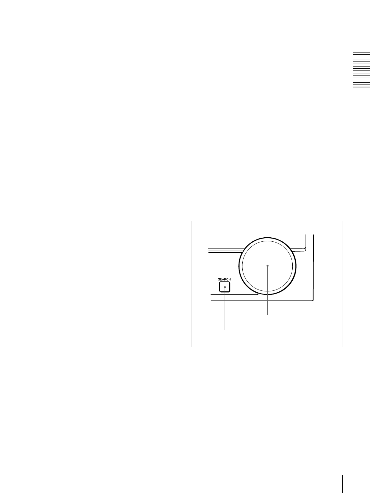
E Search control section
Chapter 1 Overview
g Cassette memory indicator
Lights when a cassette provided with a memory chip
(“cassette memory”) is loaded.
h SERVO indicator
This indicator lights when the drum servo a nd cap stan
servo are locked*.
* Servo lock: This refer s to the synchronizati on of the phase of the drum
rotation a nd the ref eren ce sign al for the ta pe t ran sp ort posi tion , so t ha t th e
video heads can trace the same pattern on the tape for playback and
recording.
i CHANNEL CONDITION indicators
These three-color indicators show the state of the playback
signal.
Green: The state of the playback sign al is good.
Yellow: The playback signal is somew hat deteriorated, but
playback is possible.
Red: The playback signal is deteriorated. When the red
indicator remains on, head cleaning or an internal
inspection is necessary.
j REPEAT indicator
This indicator lights when the REP EAT MODE menu item
(see page 62) is set to ON .
k Tape end alarm indicator
Starts flashing when the remaining c apacity of the tap e is
for about 2 minutes.
b Search dial
a SEARCH button
a SEARCH button
To use the search dial for playba ck in shuttle or jog mo de,
press this button, turning it on. Pressing the dial toggles
between shuttle and jog modes. In shuttle mode, the
SHUTTL E ind icator in the display section lights, and in
jog mode, the JOG ind icator in the display section lights.
b Search dial
Turn this to carry out playback in the modes show n in the
following table. Turning the dial clockwise lights the G
indicator in the display section and plays back in the
forward direction. Turning the dial counterclockwise
lights the g indicator in the display section and plays back
Location and Function of Parts
19
in the reverse direction. When the tape is stopped , the s
indicator in the display section lights.
Pressing this dial toggles playback between shuttle mo de
and jog mode. Wh en p laying bac k in shuttle mode, the
SHUTTL E ind icator in the display section lights, and
when playing back in jog mode, the JOG indicator lights.
You can carry out noiseless playback in the range of ±
times normal speed.
Chapter 1 Overview
Playback mod es using the search dial
Playback mode Operation and functions
Shuttle Press the SEARCH button or the search
Jog Press the SEARCH button or the search
dial so that the SHUTTLE indicator in
the display section lights, then turn the
search dial.
Playback is carried out at a speed
determined by the posi tion o f t he se arch
dial. The maximum shuttle mode
playbac k speed can be cha nged with the
SHUTTLE menu item
dial so that the JOG indicator in the
display section lights, then turn the
search dial. Playback is carried out at a
speed determined by the speed of
rotation of the sea rch dial. The pla y ba ck
speed is up to
factory default.
The search dial has no detents.
(see page 63)
±1 times n ormal speed b y
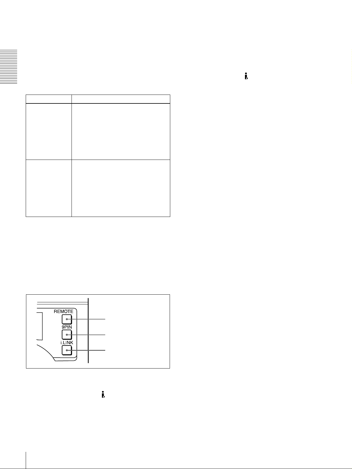
b 9PIN button
When carrying ou t remo te control between this unit and
the unit connected to the REMOTE conn ector, press this
button, turning it on.
1
/2
c i.LINK button
When carrying ou t remo te control between this unit and
the unit connected to the DV IN/OU T co nnector, press
this button, turning it on. This requires the optional DSBK1803 board to be installed.
.
You can use the SEARC H ENAB LE menu item (see pa ge
63) to select either of the following as the operation to be
performed to put the unit into search mode (shuttle or jog).
• Either press the SEAR C H button or, except during
recording/editing, turn the search dial (factory default
setting).
• Press the SEAR C H button.
F Remote control setting section
a REMOTE button
b 9PIN button
c i.LINK button
a REMO T E button
When remote-con trolling this unit from the unit connected
to the REMO TE connector or DV IN/OU T co nnec tor,
press this button, turning it on.
When reverting to local mod e to use the buttons in the tape
transport control section, press this button again, turning it
off.
Location and Function of Parts
20
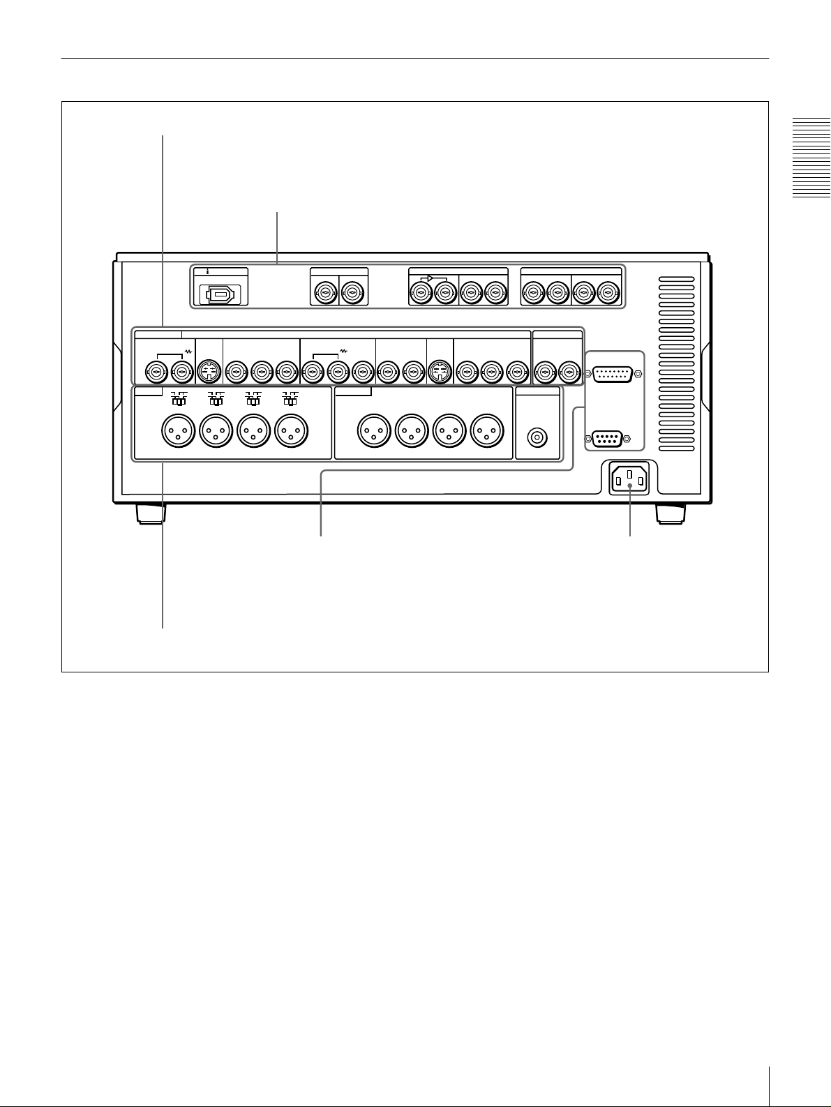
Rear Panel
A Analog video signal input/output section
B Digital signal input/output section
B-Y
LEVEL
HIGH
600
ON
Ω
SDTI(QSDI)
IN
REF.VIDEO
OUT
OUT
CH-1
DV IN/OUT
ANALOG VIDEO
VIDEO IN VIDEO OUT
LEVEL
LOW
AUDIO IN AUDIO OUT
OFF
CH-1
S VIDEO
IN
LEVEL
HIGH
LOW
OFF
ON
600
Ω
CH-2 CH-3
COMPONENT VIDEO IN
R-Y
Y
LEVEL
HIGH
HIGH
LOW
LOW
OFF
ON
600
Ω
OFF
ON
600
Ω
CH-4
(see page 22)
IN
S VIDEO
(SUPER)
CH-2 CH-3
(see page 23)
SDI
OUT
COMPONENT VIDEO OUT
Y
OUTIN 1 2
CH-4
R-Y
DIGITAL AUDIO(AES/EBU)
CH-3/4 CH-3/4
CH-1/2
IN
TIME CODE
IN
B-Y
MONITOR OUT
AUDIO
OUT
OUT
Chapter 1 Overview
CH-1/2
VIDEO CONTROL
REMOTE
~AC IN
D External device connectors
C Analog audio signal input/output section
AC IN con nector
Use the supplied power cord to co nnect this to an A C
outlet.
(see page 24)
(see page 25)
AC IN connector
Location and Function of Parts
21
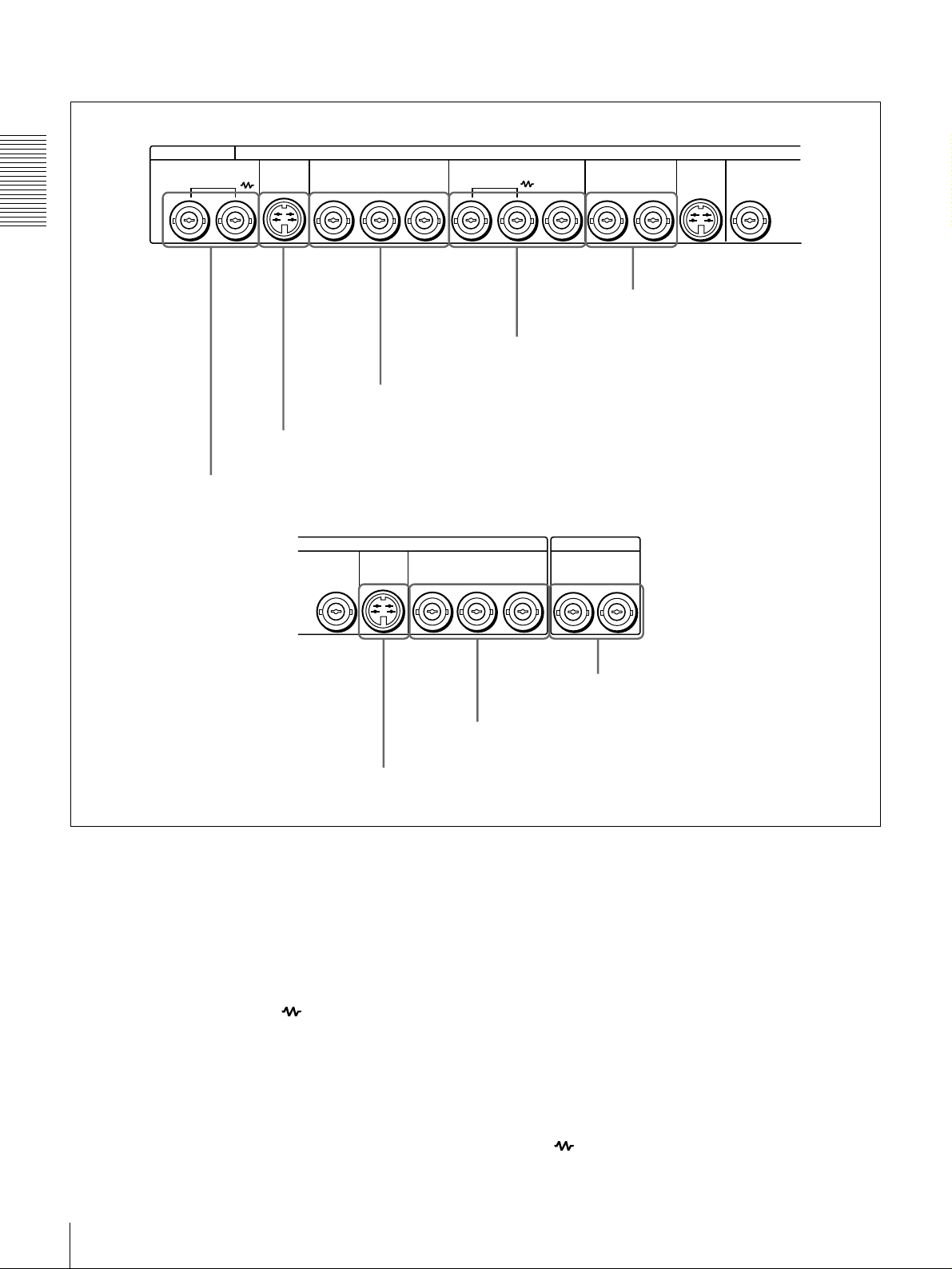
A Analog video signal input/output section
ANALOG VIDEO
VIDEO IN VIDEO OUT
Chapter 1 Overview
a VIDEO IN connectors
S VIDEO
COMPONENT VIDEO IN REF.VIDEO
IN
b S VIDEO IN connector
VIDEO OUT
R-Y
B-Y
c COMPONENT VIDEO IN Y/R
S VIDEO
2
COMPONENT VIDEO OUT
OUT IN
Y
OUT
d REF. VIDEO IN/OUT connectors
−
Y/B−Y connectors
TIME CODE
R-Y
B-Y
OUT
e VIDEO OUT 1 and 2 (SUPER)
S VIDEO
(SUPER)
connectors
OUTIN 1 2
YY
f S VIDEO OUT connector
a VIDEO IN connectors (BNC type)
Input an analog composite video signal. This con nector
block has a built-in automatic 75 Ω termination switch.
When a signal is input to the left VIDE O IN c onnec tor
with no bridging (loop-through) connection m ad e, the
connector is terminated with an im peda nce of 7 5 Ω
automatically. To connect the signal input to the left
VIDEO IN connector also to other equipment, use the right
VIDEO IN connector (marked ). When the right
VIDEO IN connector is used, the built-in 75 Ω termina tion
switch turns off automatically.
b S VIDEO IN connector (4-p in)
Input an S-video signal with sep arated Y (lumina nce) and
C (chroma: 3.58 MH z for DSR-1800 or 4.43 MHz for
DSR-1800P) components to this connector.
h TIME CODE IN/OUT connectors
g COMPONENT VIDEO OUT Y/R
−
Y/B−Y connectors
c COMPONENT VIDEO IN Y/R−Y/B−Y connectors
(BNC type )
Input analog component video signals (Y/R −Y/B−Y) to
these connectors.
d REF. (reference) VIDEO IN/O U T connectors
(BNC typ e)
Input a reference video signal. The IN connector block has
a built-in automatic 75 Ω termination switch. When a
signal is input to the left REF. VIDEO IN connector with
no bridging (loop-through) connection made, the
connector is terminated with an im peda nce o f 75 Ω
automatically. To connect the reference video signal input
to the left REF. VIDEO IN connector also to other
equipment, use the right REF. VID E O IN connector
(marked ). When the right REF. VIDEO IN conne ctor
Location and Function of Parts
22
is used, the built-in 75 Ω term ination switch turns off
automati cally.
The REF. VIDEO OU T c onnec tor outputs a reference
video signal, except when i.LINK is selected in the IN PUT
g COMPONENT VIDEO OUT Y/R−Y/B−Y
connectors (BNC type)
These connectors output analog com p onent vide o signals
(Y/R−Y/B−Y).
SELECT section (see page 16).
h TIME CODE IN/OUT connectors (BNC type)
e VIDEO OUT 1 and 2 (SUPER) connectors (BNC
type)
These connectors output analog com po site video signals.
When the CHARA. DISPLAY menu item (see page 65) is
set to ON (factory default setting), connector 2 (SUPER)
outputs a signal with superimposed text informa tion.
Input SMPTE time co de (for DSR-1800) or E BU time
code (for DSR-180 0P) ex ternally generated to the IN
connector.
The OUT conn ector outputs a time co de acc ording to the
operating state of the unit, as follows:
During playback: the playback time code
During recording: the time code gen erated by the internal
f S VIDEO OUT conn ector (4-pin)
This connector outputs an S-video signal w ith separated Y
(luminance) and C (chrom a : 3.58 MHz for DSR -1800 or
time code generator or the time code inp u t to the T IME
CODE IN con n ector. When the EE OU T P HASE menu
item (see page 67) is set to MUTE , no time code is output.
4.43 MHz for DS R-1 800P ) components.
B Digital signal input/output section (optional DSBK-1801/1802/1803 boards required)
Chapter 1 Overview
SDTI(QSDI)
IN
IN
DV IN/OUT
OUT
SDI
OUT
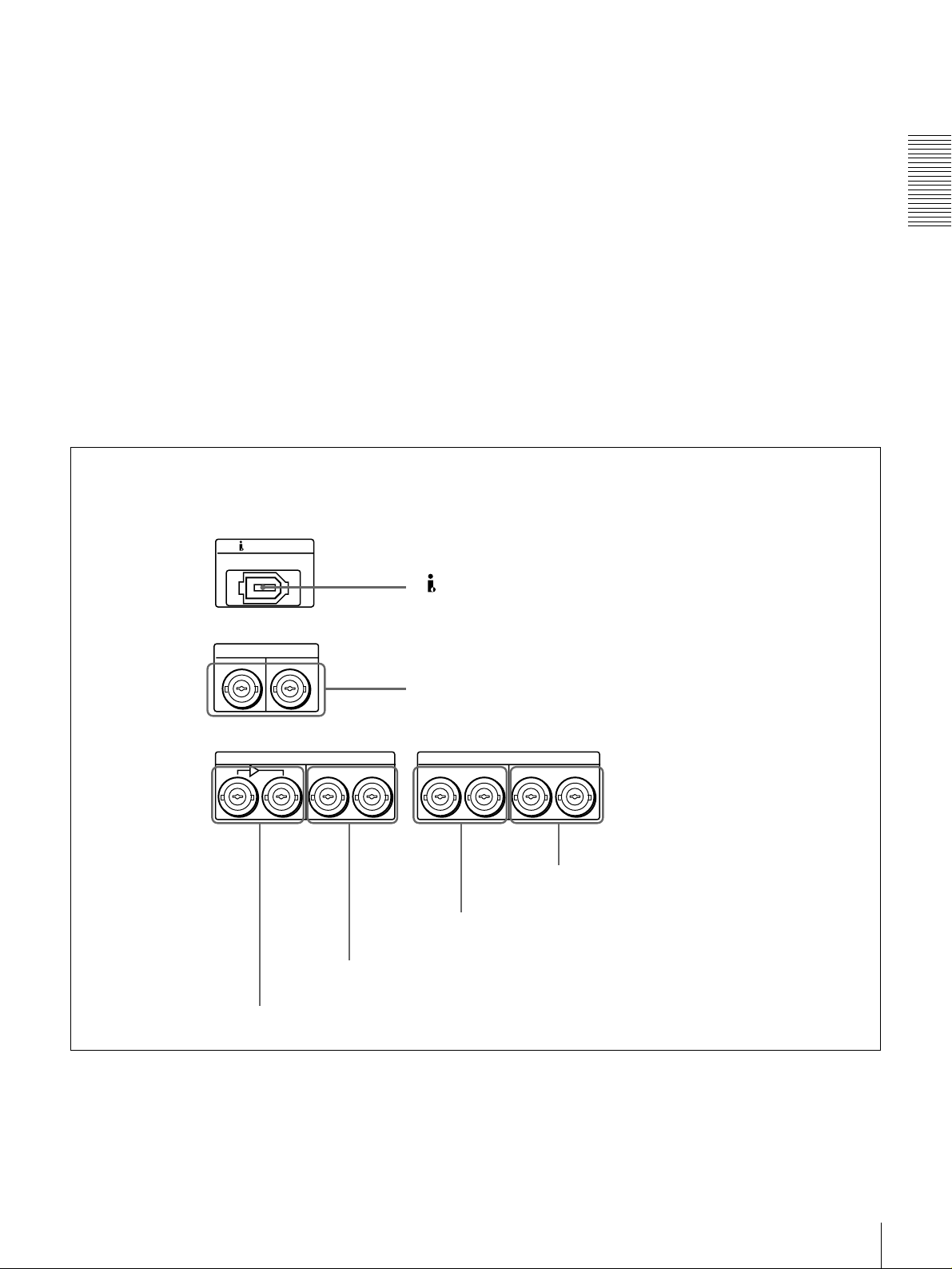
d SDI OUT connectors
a DV IN/OUT connector
b SDTI (QSDI) IN/OUT connectors
DIGITAL AUDIO(AES/EBU)
CH-3/4 CH-3/4
CH-1/2
IN
e DIGITAL AUDIO (AES/EBU) IN connectors
CH-1/2
OUT
f DIGITAL AUDIO (AES/EBU) OUT connectors
c SDI IN and active through output connectors
Location and Function of Parts
23
a DV IN/OUT connector (6-pin IEEE-1394)
(optional DSBK -1803 i.LIN K /DV Input/Output
Board required)
This i.LINK-com patible connector (subsequently referred
to also as the i.DV IN/OUT co nnector) inputs and outputs
digital video and audio signals in DV format.
Note
When searching at speeds in the ran ge +1/2 to +1/30 or
Chapter 1 Overview
1
/2 to −1/30 times normal speed, the audio signal output
−
from this connector and m onitored on externa l equipm ent
may sound differently from the audio signal played back
on th is unit.
c SDI (Serial Digital Interface) IN (input) and active
through output connectors (BN C ty pe) (optional
DSBK-1801 SD I/AES/EBU Input/Output Boar d
required)
Input digital video and audio signals in SDI form at to the
left-hand connector. The right-hand connector is for an
active-through connection.
d SDI (Serial Digital Interface) O U T connectors
(BNC type) (op tional D S B K-1801 SDI/AE S /E BU
Input/Output Board requ ired)
Output SDI-format digital video an d audio signals. The
same signals are output from both con n ectors.
b SDTI (QSDI) (Serial Data T ransport Interface
(QSDI)) IN /O U T connectors (B N C type) (optional
DSBK-1802 SDTI (Q S D I) In p u t/O u tpu t B oard
required)
The IN connector inputs and the OUT connector outpu ts
digital video and audio signals in SDTI (QS D I) forma t.
Note
When searching at speeds in the ran ge +1/2 to +1/30 or
1
/2 to −1/30 times normal speed, the audio signal outpu t
−
from this connector and m onitored on externa l equipm ent
may sound differently from the audio signal played back
on th is unit.
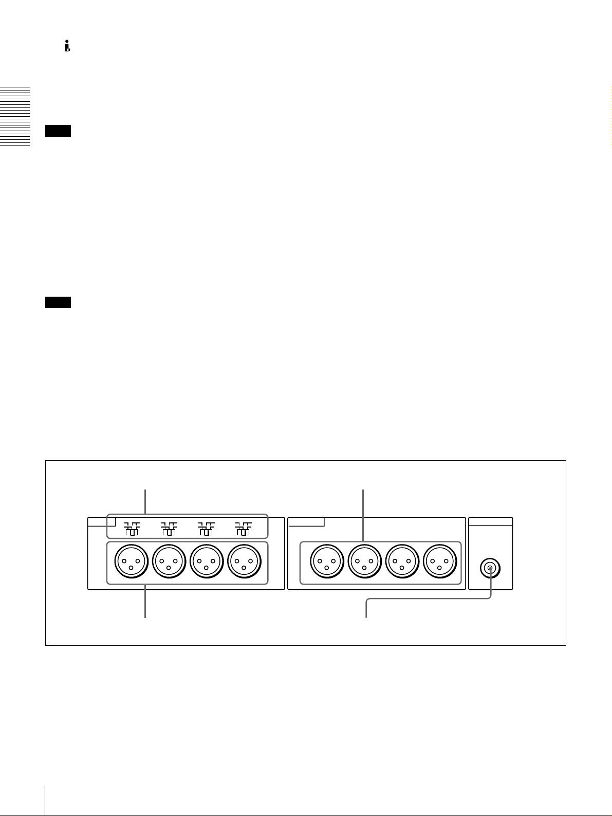
C Analog audio signal input/output section
a AUDIO IN LEVEL/600 Ω switches
e DIGITAL AUDIO (AES/EBU) IN connectors
(BNC type) (op tional D S B K-1801 SDI/AE S /E BU
Input/Output Board requ ired)
Input digital audio signals in AES/EB U form a t to these
connectors.
The left-hand connector (CH-1/2) is for aud io chan nels 1
and 2, and the right-hand connector (CH -3/4) is for audio
channels 3 and 4.
f DIGITAL AUDIO (AES/EBU) OUT connectors
(BNC type) (op tional D S B K-1801 SDI/AE S /E BU
Input/Output Board requ ired)
These connectors output digital audio signals in AE S/EBU
format.
The left-hand connector (CH-1/2) is for aud io chan nels 1
and 2, and the right-hand connector (CH -3/4) is for audio
channels 3 and 4.
c AUDIO OUT CH-1 to CH-4 connectors
LEVEL
LOW
AUDIO IN AUDIO OUT
OFF
CH-1
LEVEL
HIGH
LOW
OFF
ON
600
Ω
CH-2 CH-3
b AUDIO IN CH-1 to CH-4 connectors
600
HIGH
LEVEL
LOW
OFF
ON
Ω
600
HIGH
ON
Ω
CH-4
LEVEL
LOW
OFF
a AUDIO IN LEVEL/600 ΩΩΩΩ switches
Set these switches for each channel as shown in the
following table, according to the audio input levels to the
AUDIO IN CH-1 to CH-4 connectors and the required
impedance.
Location and Function of Parts
24
600
HIGH
ON
Ω
CH-1
CH-2 CH-3
d AUDIO MONITOR OUT connector
CH-4
MONITOR OUT
AUDIO
Settings of the AUDIO IN LEVEL/600 ΩΩΩΩ switches
Audio input Switch setting
Level Impedance
−−−−60 dBu
(microphone input)
+4/0/−3
(line audio input)
+4/0/−3
(line audio input)
a) Selectable on DSR-1800P only
a)
/−−−−6 dBu
a)
/−−−−6 dBm
High impedance
(about 20 kΩ)
High impedance
(about 20 kΩ)
600 Ω HIGH-ON
LOW-OFF
(left position)
HIGH-OFF
(middle
position)
(right position)
b AUDIO IN CH-1 (channel 1) to CH-4 connectors
(XLR 3-pin, female)
Use these connectors to connect separate channe ls of
analog audio input from a player VCR or other external
audio equipment.
You can switch the audio input level setting with the
LEVEL SELECT menu item (see page 71).
c AUDIO OUT CH-1 (channel 1) to CH-4 connectors
(XLR 3-pin, male)
These connectors output channel-1 to ch annel-4 an alog
audio signals, respectively.
It is possible to use the AUDIO OUT CH-3 and AUDIO
OUT CH-4 connectors for audio mon itor output for
channels 1 and 2, respectively (use the OUTPUT C H3 /4
menu item (see page 71)).
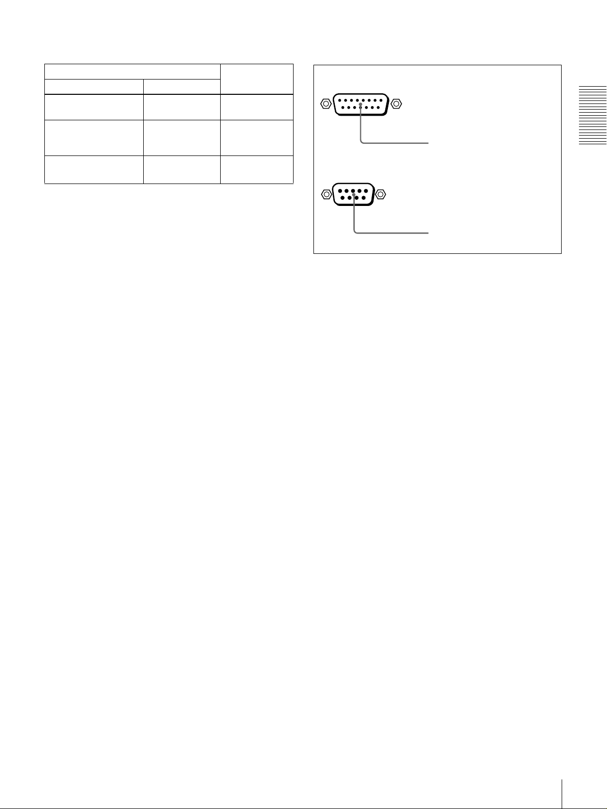
D External device connectors
VIDEO CONTROL
a VIDEO CONTROL connector
REMOTE
b REMOTE connector
a VIDEO CONTROL connector (D-sub 15-pin)
For remote control of the internal digital video processo r,
connect an optional remote control unit such as the U V R 60/60P or BVR-50/50P to this connector.
b REMOTE connector (D-sub 9-pin)
When controlling this unit from an editing con trol unit
such as the ES-3, ES-7, PVE-500, BV E -600/800 /910/
2000, or RM-450/450CE , connect the u n it to the editing
control unit via this connector using the optional 9-pin
remote control cable.
Chapter 1 Overview
d AUDIO MONITOR OUT connector (RCA phono
jack)
This connector outputs audio signals for monitoring. The
audio signals to be output from this connector can be
selected with the MONITOR SE LECT switches o n the
menu control panel.
Location and Function of Parts
25

Chapter 1 Overview
Location and Function of Parts
26

Recording and Playback
Usable Cassettes
This unit can use the DV C AM cassettes listed below.
Model name Size
PDV-64ME/94ME/124ME/184ME Standard size
PDVM-12ME/22ME/32ME/40ME Mini size
The numbers in each model name ind icate the m aximum recording/playback
time (in minutes) for each m odel. F or exa mple, the PDV-184M E has a
maximum recording/play back time of 184 minutes.
Cassettes usable fo r playback only
All consumer D V cassettes and large- and medium-size DV CPRO (25M )
cassettes are usable for playback only.
Notes
• If you insert an incorrect type of cassette, it will be automatically ejected.
• When opera ting this unit as a player, you can also use DV cassettes on the
unit. However, it is the best choice to always use DV CA M cassettes because
they are more reliable than DV cassettes w hatever your purpose may be:
playback, editing, or long-period storage of recordings.
• Cassettes that have been recorde d by a DV-format recorder can be played
back on this unit but cannot be used for recording at editing operation. When
you insert such a cassette into this unit, the NOT EDITAB LE indicator lights
up in the display section on the front panel of this unit.
Chapter
2
Usable Cassettes
27
DVCAM cassettes
Chapter 2 Recording and Playback
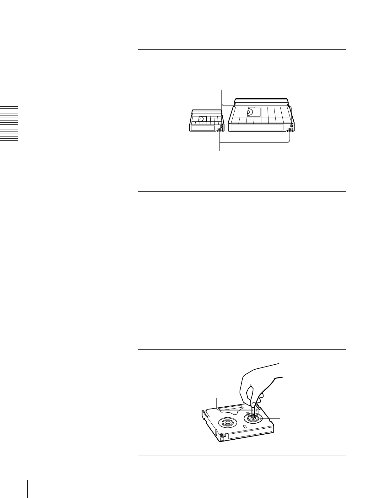
Notes on using cassettes
The following f i g ure ill u strates the D VCAM casse tt e s .
REC/SAVE switch
For details of this switch, see “Preventing accidental
erasure” on page 29
Mini size Standard size
Cassette memory
This memory is used to store ClipLink log data.
For details of ClipLink log data, see the appendix
“ClipLink Guide”(page 110).
• Before storing the cassette for a long period of time , rewind the tape to the
beginning and be sure to put the c assette in its storage case, preferably on end
instead of flat on its side.
Storing a cassette in any other condition (not rewound, out of its case, etc.)
may cause the video and audio c ontents to bec ome damaged over tim e.
• If the cassette memory co nnector (contact point) becomes dirty, connection
problems may occur, causing a loss of functions. Remove away any d ust or
dirt from this area before using the cassette.
• If the cassette is dropped on the floor or otherwise receives a hard impa ct, the
tape may become slackened and may not record and /or play back correctly.
Checking the tape for slack
For information about how to check the tape for slack , see the next section.
Using a paper clip or a similar object, turn the reel gently in the direction shown
by the arrow. If the reel does not mov e, there is no slack. Insert the cassette into
the cassette compartment, and after abo u t 10 sec onds tak e it out.
Paper clip, etc.
Reel
28
Usable Cassettes
Preventing accidental erasure
Set the REC/SA VE switch on the cassette to SA V E to preven t accidental
erasure of recorded contents.
To enable re-recording
Set the REC/SAVE switch to REC.
When this switch is set to SAVE, the unit cannot record o n the tape .
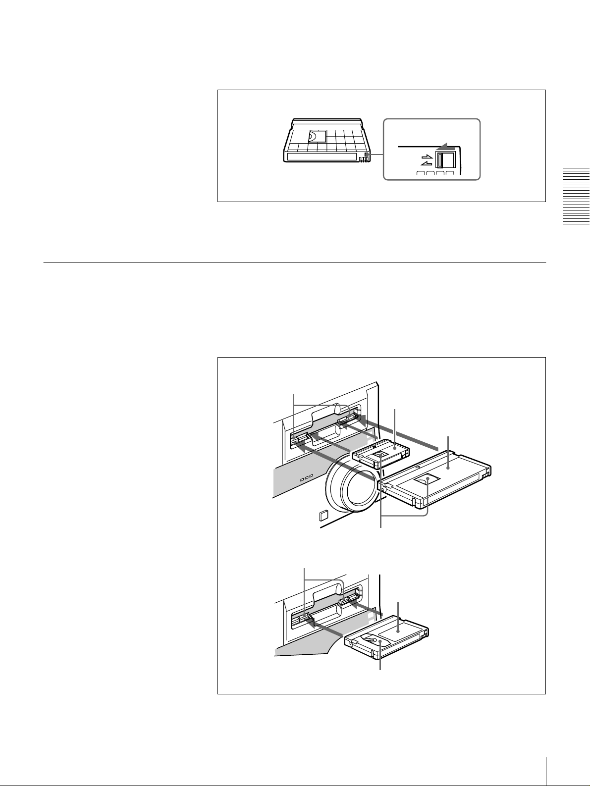
Inserting and Ejecting Cassettes
Inserting a cassette
This unit accepts three sizes of cassette: L (standard size), M (medium size:
DVCPR O) and S (mini size). When inserting a cassette in the unit, make sure
its tape window faces upward as show n in the following figure.
REC/SAVE switch
Set to SAVE
REC
SAVE
Chapter 2 Recording and Playback
Outer guides
Inner guides
Mini size (Insert the cassette into the
middle of the cassette compartment.)
Standard size
Tape window facing upward
Medium size (Align the cassette with
the outer guides, then slide it in over
the inner guides.)
Tape window facing upward
Usable Cassettes
29
No double insertion of cassettes
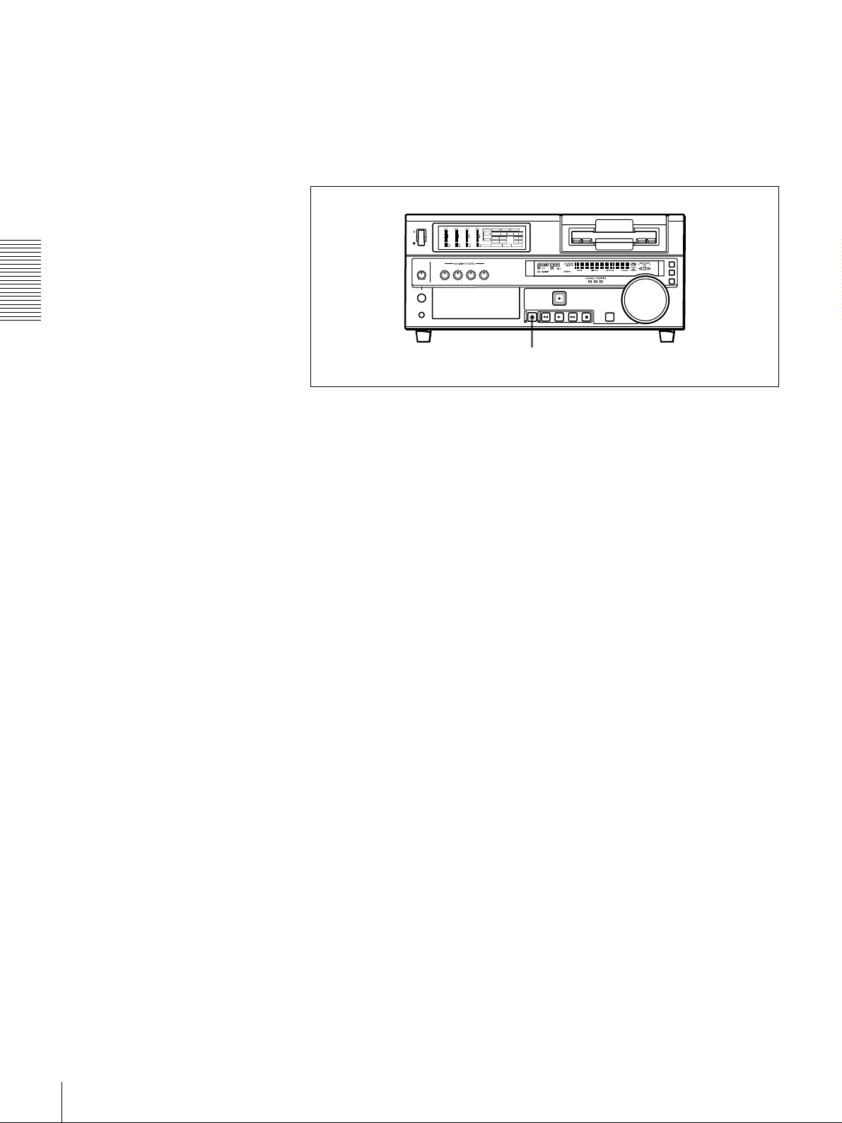
Ejecting a cassette
Chapter 2 Recording and Playback
When you insert a cassette, the orange lock-o ut plate appea rs in the cassette
compartment to prev ent dou ble insertion.
Press the EJECT button.
OVER
OVER
OVER
OVER
dB
dB
dB
dB
dB
dB
dB
dB
INPUT
0
0
-12
1
-20
0
-1
-30
-40
-2
-60
1
V:SDTI SDTI i.LINK
0
0
0
0
0
0
S VIDEO
SDI SG
COMPOSITE
Y-R,B
VIDEO
-12
1
-12
1
-12
1
CH11/2
-20
0
-20
0
-20
0
ANALOG
AES/EBU
SDI SG
AUDIO
-1
-1
-1
-30
-30
-30
ANALOG
AES/EBU
SDI SG
CH23/4
-40
-40
-40
-2
-2
-2
REC MODE
2CH4CH
PB FS
48k44.1k32k
-60
-60
-60
2
3
4
EJECT button
30
Usable Cassettes
 Loading...