


Digital
Videocassette
Recorder
3-204-974-12(1)
Operating Instructions
Before operating the unit, please read this manual
thoroughly and retain it for future reference.
DSR-1500/1500P
© 2000 Sony Corporation
Owner’s Record
The model and serial numbers are located at the bottom.
Record these numbers in the spaces provi ded below. Refer
to them whenever you call upon your Sony dealer
regarding this product.
WARNING: THIS WARNING IS APPLICABLE FOR
USA ONLY.
Using this unit at a voltage other than 120 V may require
the use of a different l ine cord o r attachment plug, or both.
To reduce the risk of fire or electric shock, refer servicing
to qualified service personnel.
Model No.
Serial No.
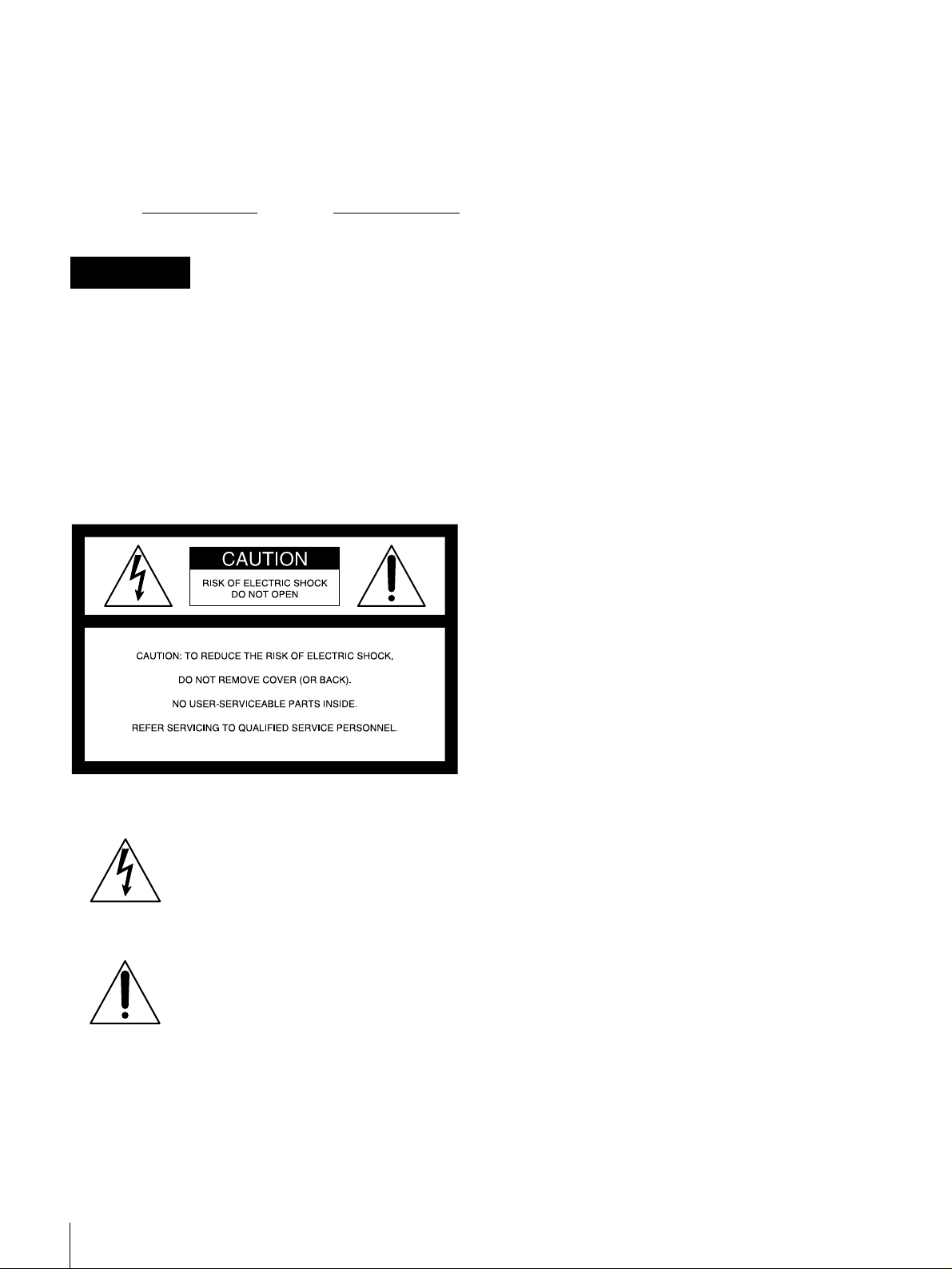
WARNING
To prevent fire or shock hazard, do not
expose the unit to rain or moisture.
To avoid electrical shock, do not open the
cabinet. Refer servicing to qualified
personnel only.
THIS APPARATUS MUST BE EARTHED.
For customers in the USA
This equipment has b een te sted and found to c omply with
the limits for a Class A digital device, pursuant to Part 15
of the FCC Rules. These limits are designed to provide
reasonable protection against harmful interference when
the equipment is operated in a commercial environment.
This equipment generates, uses, and can radiate radio
frequency energy and, if not installed and used in
accordance with the instruction manual, may cause
harmful interference to radio communications. Operation
of this equipment in a residential area is likely to cause
harmful interference in which case the user will be
required to correct the interference at his own expense.
You are cautioned that any changes or modifications not
expressly approved in this manual could void your
authority to operate this equipment.
The shielded interface cable recommended in this manual
must be used with this equipment in order to comply with
the limits for a digital device pursuant to Subpart B of Part
15 of FCC Rules.
This symbol is intended to alert the user to
the presence of uninsulated “dangerous
voltage” within the product’s enclosure
that may be of suff icient magnitude to
constitute a risk of elect r ic shock to
persons.
This symbol is intended to alert the user to
the presence of important operating and
maintenance (servicing) instructions in
the literature accompanying the
appliance.
Caution
Television programs, films, video tapes and other
materials may be copyrighted.
Unauthorized recording of such material may be contrary
to the provisions of the copyright laws.
For customers in Europe (DSR-1500P only)
This product with the C E mar kin g co mpli es wi th both the
EMC Directive (89/33 6/EEC) and the Low Voltage
Directive (73/23/EEC) issued by the Commission of the
European Community.
Compliance with these directives implies c onformity to
the following European standards:
• EN60065: Product Safety
• EN55103-1: Electromagnetic Interference (Emission)
• EN55103-2: Electromagnetic Susceptibility (Immunity)
This product is intended for use in the following
Electromagnetic Environment(s):
E1 (residential), E2 (commercial and light indust ri al) , E3
(urban outdoors) and E4 (controlled EMC environment,
ex. TV studio).
2

Table of Contents
Chapter 1 Overview
Features........................................................................5
DVCAM Format .............................................................5
Variety of Interfaces........................................................6
Compact Size ..................................................................6
Facilities for High-Efficiency Editing.............................6
Other Features.................................................................7
Optional Accessories.......................................................7
Location and Function of Parts..................................8
Front Panel......................................................................8
Rear Panel .....................................................................18
Chapter 2 Recording and Playback
Usable Cassettes.......................................................23
Inserting and Ejecting Cassettes ...................................25
Recording...................................................................27
Settings for Recording ..................................................27
Recording Procedure.....................................................30
Playback.....................................................................33
Settings for Playback ....................................................33
Playback Procedure.......................................................34
Repeat Playback—Automatic Cyclical Playback .........36
Setting Points A and B for Repeat Playback.................36
Cuing Up to Any Desired Position Set as Point
A or B ..................................................................42
Chapter 3 Convenient Functions for Editing Operation
Setting the Time Data................................................43
Displaying Time Data and Operation Mode
Indications ...........................................................43
Using the Internal Time Code Generator...................... 45
Synchronizing Internal and External Time Codes........46
Rerecording the Time Code—TC Insert Function........ 47
High-Speed and Low-Speed Search—Quickly and
Accurately Determining Editing Points ............50
Search Operations via External Equipment ..................50
Digitally Dubbing Signals in DVCAM Format..........51
Table of Contents
3

Chapter 4 Menu Settings
Menu Organization....................................................55
Menu Contents...........................................................58
Setup Menu...................................................................58
Auto Mode (AUTO FUNCTION) Execution Menu.....71
Changing Menu Settings ..........................................72
Buttons Used to Change Settings..................................72
Changing the Settings of Basic Items...........................72
Displaying Enhanced Items ..........................................74
Changing the Settings of Enhanced Items ....................74
Returning Menu Settings to Their Factory Default
Settings ................................................................75
Displaying Supplementary Status Information.......76
Chapter 5 Connections and Settings
Connections for a Digital Non-Linear Editing
System.................................................................79
Connections for a Cut Editing System....................81
Connections for an A/B Roll Editing System..........83
Connections for SDTI (QSDI) Dubbing....................89
Connections for Analog Recording.........................90
Adjusting the Sync and Subcarrier Phases............91
Chapter 6 Maintenance and Troubleshooting
Maintenance...............................................................93
Condensation.................................................................93
Regular Checks ............................................................. 93
Head Cleaning...............................................................95
Troubleshooting........................................................96
Error Messages.............................................................. 98
Alarm Messages............................................................98
Appendixes
Precautions..............................................................101
Specifications..........................................................102
ClipLink Guide.........................................................105
What Is ClipLink?.......................................................105
Example System Configuration and Operation
Flow...................................................................106
Data Generated When Shooting..................................107
Glossary...................................................................110
Table of Contents
4
Index.........................................................................113

Overview
Features
The DSR-1500/1500P is a 1/4-inch digital videocassette
recorder using the DVCAM™ digital recording format.
The unit is equipped with a full ran ge of output in terfac es,
so that it can be used as a low-cost, compac t feeder/viewer
in a non-linear editing system* without requiring any
optional boards. When using the unit as a recorder, the
optional boards available for the unit allow you to select
required input signal formats.
The unit is playback-compa tible with tapes recorded i n DV
format (excluding tapes recorded in LP mode) as well as
DVCPRO (25 Mbps) format. Playing back such tapes on
the unit does not require any adapter.
These and other features of the unit make it suitable for use
under diversified conditions. It can be used, for example,
for desk-top editing or for such applications as electronic
news gathering (ENG) and non-linear editing aboard
outside broadcast vans, at production houses or at
broadcasting stations.
* Non-linear editing: This is an editing met hod that uses video and audio
signals digitally encoded and recorded on a hard disk as digital data. When
compared with conventional (linear) editing methods, non-linear editing
offers vastly improved efficienc y in edi ting operations, for example, by
eliminating tape transport time.
The following are the principal features of the unit.
DVCAM Format
DVCAM is a professional 1/4-inch digital recording format
developed by Sony from the consumer DV component
digital format.
High picture quality and high stability
Video signals are separated into color difference signals
and luminance signals, which are encoded and co mpressed
Chapter
to one-fifth size before being recorded to ensure stable and
superb picture quality.
Because the recording is digital , multi-generation du bbing
can be performed with virtually no det erioration of quali ty.
Wide track
The recording track width i s 15 µm, 50% wider than th e 10
µm of the DV format. This ensures adequate reliability for
professional use.
High-quality PCM digital audio
PCM recording makes for a wide dynamic range and a
high signal-to-noise ratio, thereby enhancing sound
quality.
There are two recording modes: 2-channel mode (48-kHz
sampling and 16-bit quantization), which offers sound
quality equivalent to the DAT (Digital Audio Tape)
format, or 4-channel mode (32-kHz sampling and 12-bit
quantization).
Superior playback compatibility with DV
and DVCPRO (25 Mbps) formats
Tapes recorded in DV format (excluding the tapes
recorded in LP mode) as well as DVCPRO (25 Mbps)
format can be played bac k on th is unit with out requi ring a
cassette adapter. You can use the re cordings on such t apes
as source material for editing, applying such functions as
the jog audio and digital slow-motion playback as
required. Using the material, editing can be carried out to
single-frame precision.
Note
When playing back a tape recorded in DVCPRO (25
Mbps) format, the outputs in SDTI and DV (i.LINK)
formats of this unit are muted. Furthermore, it is not
possible to playback the cue-audio track of the tape.
1
Features
5

Support for three cassette sizes
There are two sizes of DVCAM cassette: standard and
mini. You can use either size with this unit.
The unit also accepts L and M sizes of DVCPRO cassette.
• When a cassette is inserted, the reel mechanism of the
unit automatically adjusts to the size of the inserted
cassette.
• The capacity of a standard cassette is 184 minutes of
Chapter 1 Overview
recording/playback, and that of a mini cassette is 40
minutes.
audio channels can be output also either as channels 1
and 2 or as channels 3 and 4.
The analog output interfaces are provided as standard so
that the unit can readily be used as a viewer, for example,
at broadcasting stations and aboard outside broadca st vans
without requiring any optional boards.
Inputting analog video and audio signals requires the
optional DSBK-1504/1504P Analog Input Board.
Compact Size
Variety of Interfaces
Digital interfaces
The following optional digital interfaces are available for
use with the unit .
• SDTI (QSDI)* (optional DSBK-1501 Digital Input/
Output Board): When the unit is fitted with the optional
DSBK-1501 board, SDTI (QSDI)-format video, audio
and time code signals can be transferre d between the unit
and the Sony EditStation at normal speed. When this unit
is connected to another DVCAM VCR, it is possible to
copy compressed signals between the two VCRs.
(You cannot use the SDTI (QSDI) and SDI (see next
paragraph) interfaces at the same time. You can select
either of the two using front panel buttons for input or
with a menu item for output.)
• SDI (serial digital interface)/AES/EBU (optional
DSBK-1501 Digital Input/Output Board): When the
unit is fitted with the opti onal DSBK- 1501 board , it can
input and output D1 (component) format digital video
and audio signals and also AES/EBU-format digital
audio signals.
• i.LINK (DV)** (optional DSBK-1503 i.LINK/DV
Input/Output Board): When the unit is fitted with the
optional DSBK-1503 board, it can input and output
digital video and audio signals in DV format.
* SDTI is the name of a standard interface establishe d a s SMPTE 305M.
QSDI is a type of SDTI. This unit u ses SDTI to t ransmit DV data , and th e
input/output connecto rs are la beled “SDTI (QSDI).”
** i.LINK and are trademarks and indi cate th at this pr oduct i s in agree ment
with IEEE1394-1995 speci fic at ions and their revisions.
The compact size of the unit makes the unit suitable for use
as a desk-top editor or feeder machine for non-linear
editing or as a viewer compatible with a full range of
digital and analog signal formats aboard an outside
broadcast van.
Facilities for High-Efficiency Editing
Digital slow motion playback
Using the frame memory function, noiseless slow motion
playback is possible at any speed in t he range ±0.5 times*
normal speed.
* The positive direction refers to forwar d mo ve me nt of the tape, and the
negative direction to reve rse movement.
Digital jog sound function
When searching at speeds in the range ±0.5 times normal
speed, the digital jog soun d function is enable d. The audi o
signal is saved in temporary memory, and replayed
according to the search speed. This allows searching on the
sound track.
Remote control
The unit can be operated by remote control from an editing
control unit that supports the RS-422A interface or an
optional SIRCS*-compatible remote control unit such as
the DSRM-10.
* SIRCS (Sony Integrated Remote Control System): A command protoco l
to remote control S on y professional videocassette r ecorders/play er s .
Analog interfaces
The unit can also use the following analog interfaces.
• Analog video: These interfaces include a component
interface, composite interface, and S-video interface.
The same BNC type input and output connectors are
used to input and output signals in different formats
selected with front panel buttons for input and menu
items for output.
• Analog au dio: The unit has two audio channels. When
in 4-channel mode, you can input two channels of audio
either as channels 1 and 2 or as channels 3 and 4. The two
Features
6
High-speed search function
The unit has a picture search function that allows you to
view color picture at playback speeds up to 85 times
normal speed in forward and reverse directions.
When remote-controlling this unit in shuttle mode from an
editing control unit or a remote control unit, you can search
at any speed in the range 0 (still) to 60 times normal speed
in both directions. You can also search frame-by-frame in
jog mode.
At search speeds up to 10 times normal speed in both
directions, you can also hear playback audio.

Quick mechanical response
When you use the tap e transport buttons of the unit, the
tape inserted in the unit responds quickly.
Superimposition function
Time code values, operation mode indications, error
messages, and other text data can be superimposed and
output in analog composite video signals.
Support for ClipLink function
In response to commands sent from the EditStation, index
pictures recorded on tape or ClipLink log data recorded in
the cassette memory can be transferred to the E ditStati on.
The EditStation operator can then efficiently use these
pictures and data in a preliminary editing session.
For an overview of the Cli pLink function, see the appendix
“ClipLink Guide” (page 105).
Chapter 1 Overview
Other Features
Menu system for functionality and
operation settings
The unit provides a menu system to make its various
functions easier to use and set up its operation conditions.
Easy maintenance functions
Self-diagnostic/alarm function: This function
automatically detects setup and connection errors,
operation faults, and ot her problems. I t also displ ays a
description of the problem, its cause, and the
recommended response on the v ideo monitor screen or
time counter display .
Digital hours meter: The digital hours meter functions
include four kinds of tally operations for operating
hours, head drum usage hours, tape transport hours,
and tape threading/un threading times. The tally r esults
can be viewed on the video monitor or the time counter
display.
AC operations
The unit operates with an AC power source in the range
100 to 240 V, 50/60 Hz.
Internal and external time codes
An internal time code generator and reader enables time
code compliant with SM PTE (for DSR -150 0)/EB U (DSR 1500P) format to be reco rded and played back. Thi s allows
editing to single frame precision.
Outputting or inputting time code (LTC) to or from an
external device is also possible using the TC IN/OUT
connectors.
The unit is also compatible with VITC.
Internal test signal generator
The unit has built-in video and audio test signal generators.
The video test signal generator can produce either a color
bar signal or a black burst signal. The audio test signal
generator can generate eit her a silent signal or a 1-kHz sine
wave signal. Menu items are provided for sel ecting the test
signals to be generated.
Video process control
For analog video output and SDI-format video output, you
can use menu items to adjust the video output level,
chroma signal output level, setup level (for DSR-1500),
black level (for DSR-1500P), and chroma phase.
Reference signal connection
The reference video input connector of the unit is provided
with a loop-through connector which can be used to
connect the input reference video signal to other
equipment. When there i s no loop-thr ough connecti on, the
reference video input con nector is au tomati call y provide d
with a 75-ohm termination.
Closed caption compatibility
Whether or not to include closed captions in a recording
can be determined with menu items (for DSR-1500 only).
Optional Accessories
DSBK-1501 Digital Input/Output Board
This interface enables digital vide o and audio signals in the
SDI or SDTI (QSDI) format (either format to be selected
with front panel buttons for input or with a menu item for
output) and also AES/EBU-format dig ital audi o signal s to
be transferred between this unit and digital Betacam VCRs
or other digital equipment.
DSBK-1503 i.LINK/DV Input/Output Board
This interface allows you to connect the unit to other
equipment provided with a Sony DV connector to carry
out editing or dubbing of digital video and audio signals.
DSBK-1504/1504P Analog Input Board
When this interface is installed, the unit can input analog
video and audio signals. The same BNC type input
connectors are used to input analog video signals in
different formats selected with front panel buttons.
The analog video signals that can be input are as follows.
• Composite video signals
• S-video signals
• Component video signa l s (Y, R−Y and B−Y)
Features
7
Location and Function of Parts
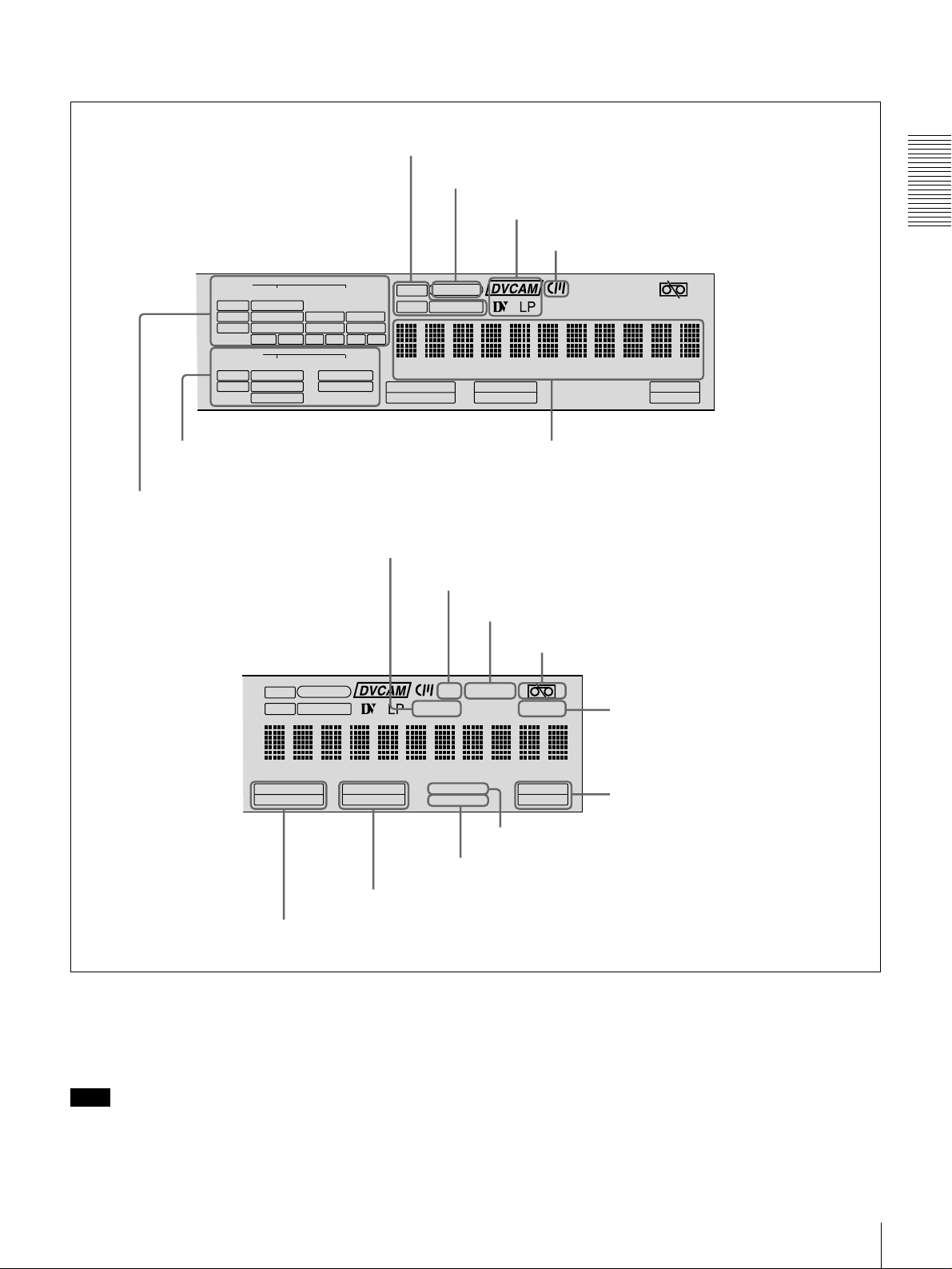
Front Panel
Chapter 1 Overview
POWER
f Cassette compartment
a POWER switch
b Audio level meters
c PHONES connector
and control knob
d SC control
e SYNC control
VAR
REC
PB
1
3
PHONES
REC/PB
LEVEL
2
OVER
OVER
dB
dB
INPUT
0
PRESET
0
-12
4
-20
-30
-40
-60
CH-
SYNC
SC
VIDEO
V:SDTI
COMPOSITE
SDTI
S VIDEO
-12
i.LINK
Y-R,B
-20
SDI SG
OUTPUT
-30
VIDEO
-40
SDI
COMPOSITE
-60
SDTI
S VIDEO
CH-
2 4
1 3
Y-R,B
MONITOR
METER
SELECT
CH-1/2 3/4 SDTI/i.LINK VIDEO
REW PLAY F FWD STOP
j METER CH-1/2 3/4
button
i MONITOR SELECT button
U-BIT
SERVO
AUDIO
CH-1 1/2
CH-2 3/4
TC NOCLEDIT
ANALOG
ANALOG
AES/EBU
AES/EBU
SDI SG SDI SG
AUDIO
HOURS MINUTES SECONDS FRAMES
CH 1/2
CH 3/4
PB FS
REC MODE
48K 44.1K 32K
2CH 4CH
INPUT SELECT
CH1 1/2 CH2 3/4
REC INHI
VITC
EDIT MODE
COUNTER
k COUNTER SELECT button
C Display section
g LOCAL/REMOTE switch
EJECT
LOCAL
REMOTE
MENU RESET(NO)
SELECT
REPEATCOUNTER
REMOTE
9P i.LINK
TC
PRESET
SET(YES)
REC
CONTROL S
l CONTROL S connector
(see page 13)
h EJECT button
A Audio input/output level
control section
(see
page 11)
B Video/audio input setting
(see page 11)
section
VAR
REC
PB
POWER
1
3
PHONES
REC/PB
LEVEL
PRESET
2
OVER
OVER
dB
dB
INPUT
0
0
V:SDTI
SDTI
-12
-12
4
SYNC
SC
i.LINK
-20
-20
OUTPUT
-30
-30
-40
-40
SDI
-60
-60
SDTI
CH-
CH-
2 4
1 3
MONITOR
METER
SELECT
CH-1/2 3/4 SDTI/i.LINK VIDEO
REW PLAY F FWD STOP
D Tape transport control
section
VIDEO
COMPOSITE
S VIDEO
Y-R,B
SDI SG
VIDEO
COMPOSITE
S VIDEO
Y-R,B
CH-1 1/2
ANALOG
AES/EBU
SDI SG SDI SG
U-BIT
SERVO
AUDIO
CH-2 3/4
TC NOCLEDIT
ANALOG
AES/EBU
AUDIO
HOURS MINUTES SECONDS FRAMES
CH 1/2
CH 3/4
PB FS
REC MODE
48K 44.1K 32K
2CH 4CH
INPUT SELECT
CH1 1/2 CH2 3/4
(see page 16)
VITC
EDIT MODE
REC INHI
COUNTER
SELECT
REC
REPEATCOUNTER
REMOTE
9P i.LINK
EJECT
LOCAL
REMOTE
MENU RESET(NO)
TC
SET(YES)
PRESET
CONTROL S
E Menu control section
(see page 17)
Location and Functio n of Parts
8

a
a POWER switch
aa
Press the “” side to power on the unit. This causes the
audio level meters and the display section to light. To
power off the unit, press the “” side of the switch.
b
b Audio level meters
bb
These two meters indicate the recording audio levels
during recording or EE mode* and the playback audio
levels during playback. When the audio level indicated on
a meter exceeds 0 dB, the OVER indicator for the meter
lights.
The short bars to th e right of le vel indi catio n bars i ndica te
that those levels are reference audio recording levels.
The settings made with the METER CH-1 /2 3/4 button and
MONITOR SELECT button select the audio channels for
level indications on these meters as follows.
When CH-1/2 mode is selected with the METER CH-1/
2 3/4 button:
Every time the MONITOR SELECT button is pressed,
the audio channel selection for level indic ations on the
two meters cycles through the following options.
• CH-1 (channel 1) only
Only the CH-1 indicator lights.
• CH-2 (channel 2) only
Only the CH-2 indicator lights.
• CH-1 and CH-2 (channels 1 and 2)
Both the CH-1 and CH-2 indicators light.
When CH-3/4 mode is selected with the METER CH-1/
2 3/4 button:
Every time the MONITOR SELECT button is pressed,
the audio channel selection for level indic ations on the
two meters cycles through the following options.
• CH-3 (channel 3) only
Only the CH-3 indicator lights.
• CH-4 (channel 4) only
Only the CH-4 indicator lights.
• CH-3 and CH-4 (channels 3 and 4)
Both the CH-3 and CH-4 indicators light.
d
d SC (subcarrier phase) control
dd
Turn this control to accurately adjust the subcarrier phase
of the composite video output signal of the unit with
respect to the reference video signal. Use a cross-point
(Phillips) screwdriver to turn it.
e
e SYNC (synchronization phase) control
ee
Turn this control to accurately adjust the synchro nization
phase of the output video signal of the unit with respe ct to
the reference video signal. Use a cross-point (Phillips)
screwdriver to turn it.
f
f Cassette compartment
ff
Accepts DVCAM, DV and DVCPRO (25 Mbps)
videocassettes.
For details of usable cassettes, see page 23.
g
g LOCAL/REMOTE switch
gg
Selects whether the unit is operate d from it s front pan el or
from external equipment.
REMOTE: The unit is operated from external equipment
connected to the REMOTE connector or i.DV IN/
OUT connector (when the optional DSBK-1503
i.LINK/DV Input/Output Board is installed) on the
rear panel.
LOCAL: The unit is operated from its front panel or from
a SIRCS-compa tib le re mo te c ontro l uni t conne cte d to
the CONTROL S connector on the front panel.
h
h EJECT button
hh
When you press this button, the cassette is automatically
ejected after a few seconds.
Chapter 1 Overview
* E-E mode: Abbreviation of “Electric-to-Electr ic mode.” In this mode,
video and audio signals input to the VCR are output after passing through
internal electric circuits, but not through magnetic conversion circuits such
as heads and tapes. This can be used t o che ck input signals and for
adjusting input signal levels.
c
c PHONES connector (stereo phone jack) and
cc
control knob
Connect stereo headphones to the connector for audio
monitoring during recording or playback. The control
knob controls the volume of the headphones. It also
controls the level of the audio signal output from the
MONITOR connector on the rear panel.
The settings made with the METER CH-1 /2 3/4 button and
MONITOR SELECT button select the audio channels for
audio output via this connector. The same channel
selection as for the audio level meters applies to this
connector.
Location and Function of Parts
9
i
i MONITOR SELECT button
ii
Use this button and the METER CH-1/2 3/4 button to
select the audio channels:
• for level indications on the audio level meters
• for audio output via the PHONES connector on the front
panel
• for audio output via the MONITOR connector on the
rear panel
Depending on the setting made with the METER CH-1/2
Chapter 1 Overview
3/4 button, the channels for output to the above meters and
connectors are selected as follows.
When CH-1/2 mode is selected with the METER CH-1/
2 3/4 button:
k
k COUNTER SELECT button
kk
Selects the type of time data to be shown in the tim e
counter display. Each press of this button cycles through
the following three indicator display options:
• COUNTER (CNT: count value of the time counter )
• TC (time code)
• U-BIT (user bits)
Note
If the LOCAL/REMOTE switch is set to REMOTE, the
COUNTER SELECT button does not operate while the
tape is moving. In this c ase, make the time data selection
via the external equipment connected to the REMOTE
connector on the rear panel.
Audio level meters PHONES
CH-1 (channel 1) only.
Only the left meter lights.
CH-2 (channel 2) only.
Only the right meter
lights.
CH-1 and CH-2 (channe ls
1 and 2).
Both the left and right
meters light.
connector
Channel 1 only
(monaural)
Channel 2 only
(monaural)
Channels 1
and 2 (stereo)
MONITOR
connector
Channel 1 only
Channel 2 only
Channels 1
and 2 (mixed)
When CH-3/4 mode is selected with the METER CH-1/
2 3/4 button:
Audio level meters PHONES
CH-3 (channel 3) only.
Only the left meter lights.
CH-4 (channel 4) only.
Only the right meter
lights.
CH-3 and CH-4 (channe ls
3 and 4).
Both the left and right
meters light.
connector
Channel 3 only
(monaural)
Channel 4 only
(monaural)
Channels 3
and 4 (stereo)
MONITOR
connector
Channel 3 only
Channel 4 only
Channels 3
and 4 (mixed)
l
l CONTROL S connector (stereo minijack)
ll
Connect a SIRCS-compatible remote control unit such as
the DSRM-10 to this connector.
j
j METER CH-1/2 3/4 button
jj
Pressing this button toggles the audio level meter mode
between CH-1/2 (cha nnels 1 an d 2) and CH -3/4 ( channel s
3 and 4).
The settings made with this button and the MONITOR
SELECT button sele ct the channels for level indications
and audio output.
For more details, see “i MONITOR SELECT button.”
Location and Functio n of Parts
10
A Audio input/output level control section
B Video/audio input setting section
a RE C/PB LEVE L control knobs
1
3
VAR
REC
PB
a
a REC/PB LEVEL control knobs
aa
REC/PB
LEVEL
PRESET
b VAR switch
2
4
These knobs used to control audio levels function
differently depending on the setting of the VAR switch as
follows.
V AR switch
setting
PRESET Control knobs are not effective.
REC Control the analo g/digital audio i nput le v els on
PB Control the analog/digital audio output levels
b
b VAR switch
bb
Functions of control knobs
The analog aud io inpu t/output l e ve ls ar e set t o
the reference level set with the LEVEL
SELECT menu item
channels 1 to 4 during recording.
on channels 1 to 4 during playback.
(see page 66)
.
Use to switch the way in which the REC/PB LEVEL
control knobs function.
SDTI/i.LINK VIDEO
a SDTI/i.LINK button
a
a SDTI/i.LINK (SDTI (QSDI) interface/i.LINK
aa
INPUT SELECT
b VIDEO button
CH1 1/2 CH2 3/4
c CH1 1/2 button
d CH2 3/4 button
selection) button
Each press of this button cycles through the following
input signal selection options.
• Digital video signal in SDTI (QSDI) format input to the
SDI/SDTI (QSDI) IN connector (optional DSBK-1501
board required)
When this is selected, use the CH1 1/2 button and CH2
3/4 button to select the required input audio signals.
Note
In this case, the phases of the selected audio signals
will be about two frames ahead of the phase of the
digital video signal in SDTI (QSDI) form at.
• Digital video and audio signals in SDTI (QSDI) format
input to the SDI/SDTI (QSDI) IN connector (optional
DSBK-1501 board required)
• Digital video and audio signals in i.LINK-compatible
DV format input to the i.DV IN/OUT connector
(optional DSBK-1503 board required)
The selection made with this button is indicated in the
INPUT signal display section (see page 14).
Chapter 1 Overview
b
b VIDEO button
bb
Each press of this button cycles through the following
input video signal selection options.
•
C
omposite video signal input to the VIDEO IN
connector (option al DSBK-15 04/1504P b oard requir ed)
• S-video (separated Y and C) signals input to the VIDEO
IN connectors (optional DSBK-1504/1504P board
required)
• Y, R−Y and B−Y component video signals input to the
VIDEO IN connectors (optional DSBK-1504/1504P
board required)
• SDI video signal input to the SDI/SDTI (QSDI) IN
connector (optional DSBK-1501 board required)
• Video test signal (selected with the INT VIDEO SG
menu item (see page 64)) generated by the internal
signal generator
The selection made with this button is indicated by the
VIDEO indicators in the INPUT signal displ ay section (see
page 13).
Location and Function of Parts
11

c
c CH1 1/2 (audio channel 1 or 1/2) button
cc
Each press of this button cycles through the following
input audio signal selection options for audio channel 1
(when in 2-channel mode) or for audio channels 1 and 2
(when in 4-channel mode).
• Analog audio signal input to the AUDIO IN 1/3
connector (optional DSBK-1504/1504P board required)
• Digital audio signal in AES/EBU format input to the
AUDIO (AES/EBU) IN 1/2 connector (optional DSBK-
Chapter 1 Overview
1501 board required)
• SDI audio signal input to the SDI/SDTI (QSDI) IN
connector (optional DSBK-1501 board required)
• Audio test signal (selected with the INT AUDIO SG
menu item (see page 66) generated by the internal signal
generator
The selection made with this button is indicated by the
AUDIO CH-1 1/2 indicators in the INPUT signal display
section (see page 13).
When analog audio is selected (optional DSBK-1504/
1504P board required), the signal input to the AUDIO IN
1/3 connector is recorded either on channel 1 (when in 2channel mode) or on channels 1 and 3 (when in 4-cha nnel
mode). That is, in 4-channel mode, the same analog au dio
signal is recorded on channels 1 and 3. Using the REC/PB
LEVEL control knobs with the VAR switch set to REC, it
is possible to adjust the audio levels on the two channels
separately.
You can switch the audio recording mode with the REC
MODE menu item (see page 65). The selection i s indicated
by the REC MODE display on the front panel.
d
d CH2 3/4 (audio channel 2 or 3/4) button
dd
Each press of this button cycles through the following
input audio signal selection options for audio channel 2
(when in 2-channel mode) or for audio channels 3 and 4
(when in 4-channel mode).
• Analog audio signal input to the AUDIO IN 2/4
connector (optional DSBK-1504/1504P board required)
• Digital audio signal in AES/EBU format input to the
AUDIO (AES/EBU) IN 3/4 connector (optional DSBK1501 board required)
• SDI audio signal input to the SDI/SDTI (QSDI) IN
connector (optional DSBK-1501 board required)
• Audio test signal (selected with the INT AUDIO SG
menu item (see page 66) generated by the internal signal
generator
The selection made with this button is indicated by the
AUDIO CH-2 3/4 indicators in the INPUT signal display
section (see page 13).
When analog audio is selected (optional DSBK-1504/
1504P board required), the signal input to the AUDIO IN
2/4 connector is recorded either on channel 2 (when in 2channel mode) or on channels 2 and 4 ( when i n 4-channel
mode). That is, in 4-channel mode, the same analog audi o
signal is recorded on channels 2 and 4. Using the REC/PB
LEVEL control knobs with the VAR switch set to REC, it
is possible to adjust the audio levels on the two channels
separately.
You can switch the audio recording mode with the REC
MODE menu item (see page 65). The selection i s indicated
by the REC MODE display on the front panel.
Location and Functio n of Parts
12
C Display section
d Time data type indicators
e SE RVO indica tor
f Recording/playback tape format indicators
g Cassette memory indicator
Chapter 1 Overview
INPUT
VIDEO
V:SDTI
COMPOSITE
SDTI
S VIDEO
i.LINK
Y-R,B
SDI SG
OUTPUT
VIDEO
SDI
COMPOSITE
SDTI
S VIDEO
Y-R,B
b OUTPUT signal display section
a INPUT signal display section
U-BIT
TC NOCLEDIT
AUDIO
CH-1 1/2
CH-2 3/4
ANALOG
ANALOG
AES/EBU
AES/EBU
SDI SG SDI SG
AUDIO
CH 1/2
CH 3/4
SERVO
U-BIT
SERVO
TC NOCLEDIT
HOURS MINUTES SECONDS FRAMES
PB FS
48K 44.1K 32K
REC MODE
2CH 4CH
REC INHI
VITC
EDIT MODE
9P i.LINK
c Time counter display
h NO EDIT indicator
i CL indicator
j REC INHI indicator
k Tape end alarm indicator
REC INHI
REPEATCOUNTER
l REPEAT indicator
REPEATCOUNTER
REMOTE
HOURS MINUTES SECONDS FRAMES
PB FS
48K 44.1K 32K
REC MODE
2CH 4CH
VITC
EDIT MODE
o REC MODE display
n PB Fs display
a
a INPUT signal display section
aa
Indicates the input video and audio signal formats selected
with the INPUT SELECT buttons (SDTI/i.LINK, VIDEO,
CH1 1/2, and CH2 3/4 buttons).
Note
The indicators without the corresponding optional boards
installed in the unit do not light.
REMOTE
9P i.LINK
m Rem ote mode indicators
q VITC indicator
p ED IT MODE indica t o r
V:SDTI indicator: Lights when the digital video signal
only in SDTI (QSDI) form at is selected (optional
DSBK-1501 board required).
SDTI indicator: Lights when the digital video and audio
signals in SDTI (QSDI) format are selected (optional
DSBK-1501 board required).
i.LINK indicator: Lights when the digi tal video and audio
signals in i.LINK- compatibl e DV format are selected
(optional DSBK-1503 board required).
Location and Function of Parts
13
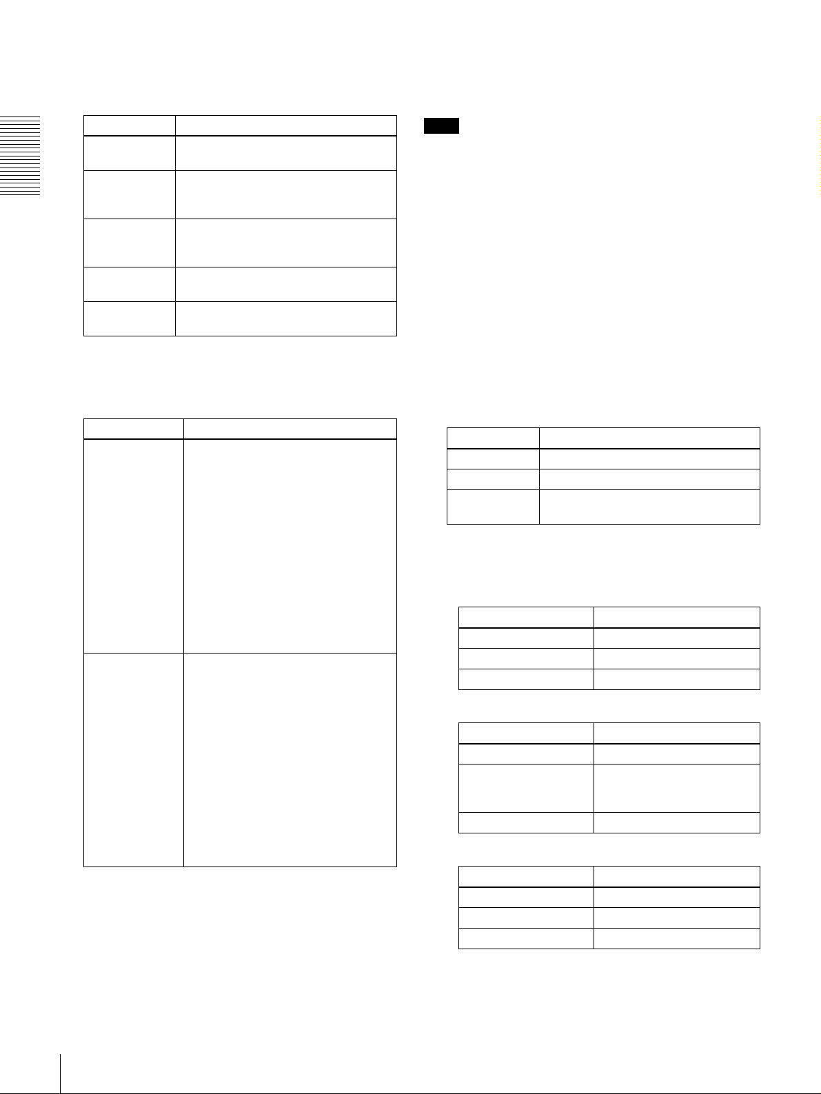
VIDEO indicators: The indicator (COMPOSITE, S
VIDEO, Y−R,B, SDI, or SG) corresponding to the
selected input video signal format lights.
b
b OUTPUT signal display section
bb
Indicates the output video and audio signal format selecte d
with the IN TERFACE SELEC T menu items (se e page 67).
Indicators Meanings
COMPOSITE Composite video signal (optional
DSBK-1504/1504P board required)
S VIDEO S-video (separated Y and C) signals
Chapter 1 Overview
Y−R,B Y, R−Y and B−Y component video
SDI SDI video signal (optional DSBK-1501
SG Video test signal (factory default
(optional DSBK-1504/1504P board
required)
signals (optional DSBK-1504/1504P
board required)
board required)
setting)
AUDIO indicators: Comprise the CH-1 1/2 indicator and
CH-2 3/4 indicator, un der each of which there ar e four
more indicators (ANALOG, AES/EBU, SDI, and SG).
They indicate the selected input audio signal formats.
Indicators Functions
CH-1 1/2
(ANALOG, AES/
EBU, SDI, SG)
CH-2 3/4
(ANALOG, AES/
EBU, SDI, SG)
The indicator corresponding to the
signal format sel ect ed for audio input
to channel 1 (when in 2-channel
mode) or to channels 1 and 2 (when
in 4-channel mode) lights.
ANALOG: Analog audio signal
(optional DSBK-1504/1504P
board required)
AES/EBU: Digital audio signal in
AES/EBU format (optional
DSBK-1501 board required)
SDI: SDI audio signal (optional
DSBK-1501 board required)
SG: Audio test signal (factory default
setting)
The indicator corresponding to the
signal format sel ect ed for audio input
to channel 2 (when in 2-channel
mode) or to channels 3 and 4 (when
in 4-channel mode) lights.
ANALOG: Analog audio signal
(optional DSBK-1504/1504P
board required)
AES/EBU: Digital audio signal in
AES/EBU format (optional
DSBK-1501 board required)
SDI: SDI audio signal (optional
DSBK-1501 board required)
SG: Audio test signal (factory default
setting)
Note
The indicators without the corresponding optional boards
installed in the uni t do not light.
SDI indicator: Lights when the digital video and audio
signals in SDI format are selected (optional DSBK1501 board required).
The SDI video and audio signals are output to the SDI/
SDTI (QSDI) OUT1 and OUT2 connectors.
SDTI indicator: Lights when the digital video and audio
signals in SDTI (QSDI) format are selected (optional
DSBK-1501 board required).
The video and audio signals in SDTI (QSDI) format
are output to the SDI/SDTI (Q SDI) OUT1 a nd OUT2
connectors.
VIDEO indicators: The indicator (COMPOSITE, S
VIDEO, or Y−R,B) corresponding to the selected
output analog video signal format lights.
Indicators Meanings
COMPOSITE Composite video signal
S VIDEO S-video (separated Y and C) signals
Y−R,B Y, R−Y and B−Y component video
signals
This selection determines the signals output from the
Y/CPST, R−Y/C/CPST, and B−Y/CPST (SUPER)
connectors as follows.
• When COMPOSITE is selected:
Connectors Output signals
Y/CPST Composite signal
R−Y/C/CPST Composite signal
B−Y/CPST (SUPER) Composite signal
• When S VIDEO is selected:
Connectors Output signals
Y/CPST Y signal
R−Y/C/CPST C signal
(3.58 MHz for DSR-1500/
4.43 MHz for DSR-1500P)
B−Y/CPST (SUPER) Composite signal
• When Y−−−−R,B is selected:
Connectors Output signals
Y/CPST Y signal
R−Y/C/CPST R−Y signal
B−Y/CPST (SUPER) B−Y signal
Location and Functio n of Parts
14

AUDIO indicators: Comprise the CH 1/2 indicator and
CH 3/4 indicator to indicate the channel selection for
analog audio output from the AUDIO OUT 1/3 and
AUDIO OUT 2/4 connectors.
Indicators Functions
CH 1/2 Lights when channels 1 and 2 are
selected f or analog audio outp ut from
the A UDIO OUT 1/3 and AUDIO OUT
2/4 connectors
CH 3/4 Lights when channels 3 and 4 are
selected f or analog audio outp ut from
the A UDIO OUT 1/3 and AUDIO OUT
2/4 connectors
.
.
You can change the channel selection with the AUDIO
OUTPUT menu item (see page 67).
c
c Time counter display
cc
Indicates the count value of the time counter, time code,
VITC, or user bit data depending on the settings of the
COUNTER SELECT button and t he TC SELECT menu
item (see page 62).
Also used to display error messages, edit data, setu p menu
data, etc.
g
g Cassette memory indicator
gg
Lights when a cassette provided with a memory chip
(“cassette memory”) is loaded.
h
h NO EDIT (not editable) indicator
hh
Lights during playback of a tape t hat con ta ins a recordi ng
in other than the DVCAM format. When this i ndica to r is
lit, the recordings contained in the tape can be used as
source material for editing, but editing operations such as
insert editing and assemble editing cannot be performed.
This indicator also lights when the audio recording mode
selected on this unit do es not coincide with that of the
loaded tape during editing operation.
i
i CL (ClipLink) indicator
ii
Lights when a cassette is loaded on which ClipLink log
data is stored in the cassette memory.
For details of ClipLink log data, see the appendix
“ClipLink Guide” (page 105).
j
j REC INHI (recording inhibit) indicator
jj
Lights when the REC/SAVE switch on the loaded cassette
is in the SAVE positi on (recording inhibited).
Chapter 1 Overview
d
d Time data type indicators
dd
One of the three indicators (COUNTER, U-BIT, or TC)
lights to indicate the type of time data currently shown in
the time counter display.
COUNTER: Count value of the time counter
U-BIT: User bit data
TC: SMPTE time code (for DSR-150 0) or EBU ti me code
(for DSR-1500P)
e
e SERVO (servolock) indicator
ee
Lights when the drum servo and capstan servo are locked.*
* Servolock: Synchronizing the drum rotat i on pha se and tape transport
phase with a reference signal during playback and record in g so tha t t he
video heads scan the tape in the sam e pa ttern during playback and
recording.
f
f Recording/playback tape format indicators
ff
DVCAM: This lights when a tape recorded in DVCAM
format is played back.
DV: This lights when a tape recorded in consumer DV
format is played back.
LP: This flashes along with “DV” when a tape recorded i n
LP mode is played back.
Video recorded in LP mode cannot be played back
correctly and audio is muted.
When a tape recorded in DVCPRO (25 Mbps) format or
any other format than those mentioned above is played
back, none of the above indicators lights.
k
k Tape end alarm indica tor
kk
Starts flashing when the remaining capacity of the ta pe is
for about 2 minutes.
l
l REPEAT (repeat playback) indicator
ll
Lights when the REPEAT MODE menu item (see page
58) is set to ON to enable the repeat playback function.
m
m Remote mode indicators
mm
REMOTE: Lights when the LOCAL/REMOTE switch is
set to REMOTE to remote control the unit from either
an editing control unit connected to the REMOTE
connector or equipment connected to the i.DV IN/
OUT connector (when the opt ional DSBK-1503 board
is installed).
9P: Lights when the REMOTE I/F menu item (see page
67) is set to 9PIN.
i.LINK: Lights when the REMOTE I/F menu item (see
page 67) is set to i.LINK (option al DSBK-1503 boa rd
required).
n
n PB Fs (playba ck audio sampling f requency) display
nn
During playback, this indicates the playback audio mode
in which the tape being played back was recorded.
48K indicator: Lights durin g playback of a t ape reco rded
in 2-channel mode (48 kHz).
44.1K indicator: Lights during p l ayback of a tape
recorded in 2-channel mode (44.1 kHz).
32K indicator: Lights durin g playback of a t ape reco rded
in 4-channel mode (32 kHz).
Location and Function of Parts
15
o
o REC MODE (audio recording mode) display
oo
This indicates the audi o recording mode cur rently selected
with the REC MODE menu item (see page 65).
2CH indicator: Lights in 2-channel mode (48 kHz).
4CH indicator: Lights in 4-channel mode (32 kHz).
Chapter 1 Overview
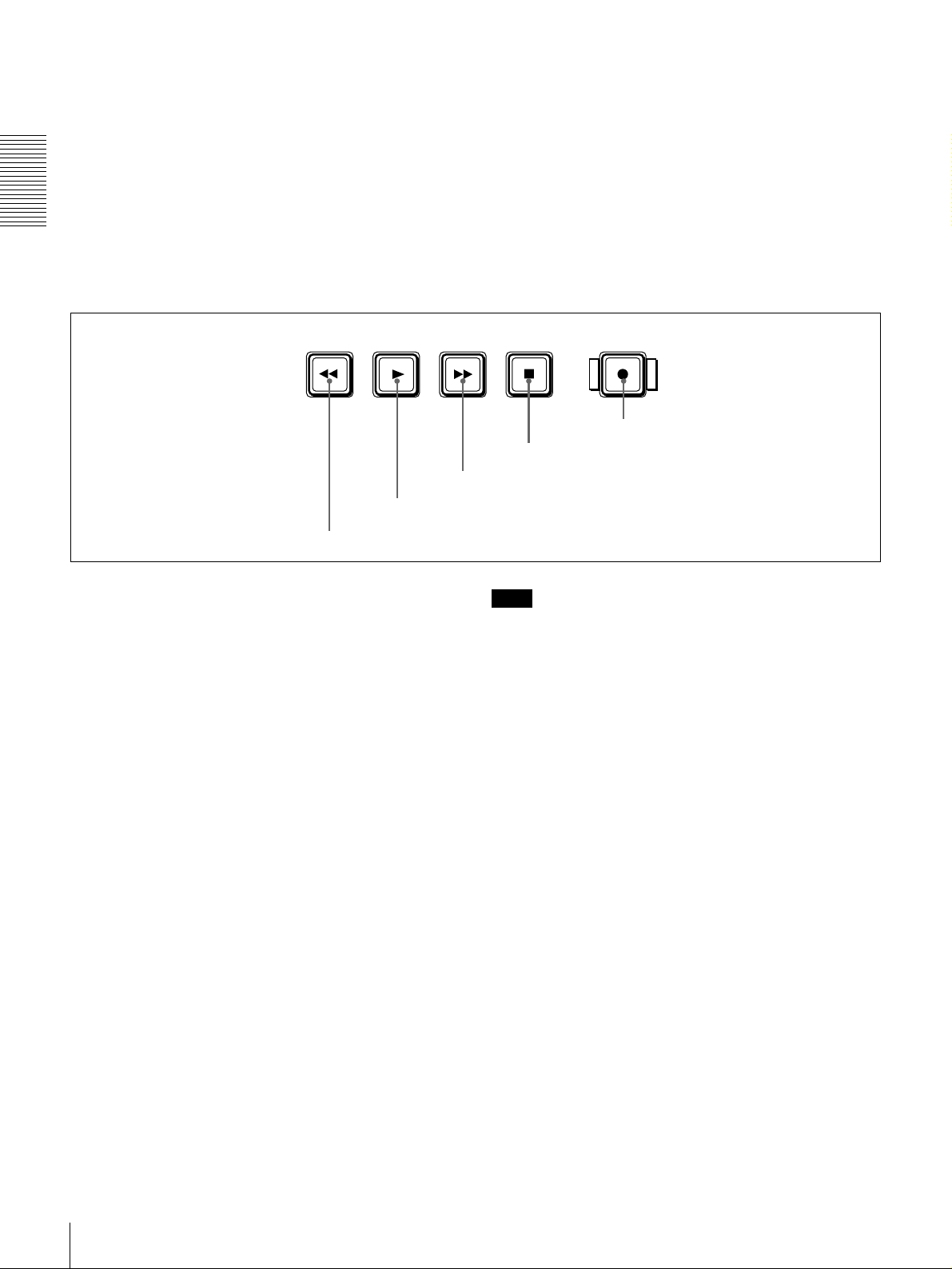
D Tape transport control section
REW PLAY F FWD STOP REC
a REW button
c F FWD button
b PLAY button
p
p EDIT MODE indicator
pp
Lights when this unit is selected as the recorder VCR
under the control of either an editing control unit
connected to the REMOTE connector or equipment
connected to the i.DV IN/OUT connector (when the
optional DSBK-1503 board is installed).
q
q VITC indicator
qq
Lights when VITC is being read or recorded regard less of
the data shown in the time counter display.
e REC button
d STOP button
a
a REW (rewind) button
aa
When you press this button, it lights and the tape starts
rewinding.
When the F. FWD/REW menu item under the AUTO EE
SELECT menu item (see page 59) is set to PB, the picture
appears on the monitor du ring rewind (maximum 8 5 times
normal speed).
b
b PLAY button
bb
When you press this bu tt on, it lights and p la yback begins.
If you press this button during recording or editing, the
recording or editing operation is stopped and this unit
enters playback mode.
c
c F FWD (fast forward) button
cc
When you press this button, it lights and the tape is fast
forwarded.
When the F. FWD/REW menu item under the AUTO EE
SELECT menu item (see page 59) is set to PB, the picture
appears on the monitor during fa st for ward ( maxi mum 85
times normal speed).
d
d STOP button
dd
Press this button to stop the current tape transport
operation.
Note
When the LOCAL/REMOTE switch is set to REMOTE
(the REMOTE indicator is lit), no tape transport control
buttons other than th e EJECT and STOP buttons will work.
This can be changed with the LOCAL ENABLE menu
item (see page 59).
e
e REC (record) button
ee
When you press this button whil e holding down the PLAY
button, it lights and recording begins.
Location and Functio n of Parts
16

E Menu control section
a MENU button
b RESET (NO) button
MENU RESET(NO)
TC
PRESET
a
a MENU button
aa
SET(YES)
Press this button to display the me nu on the monitor screen
and the time counter display. Press it again t o exit the menu
display.
c TC PRESET button
d SET (YES) button
e fFgG buttons
e
e fFgG (arrow) buttons
ee
Use these buttons to move around the menu items, and al so
to modify the initial time code value an d user bit data.
When the SEARCH ENABLE menu item (see page 59) is
set to ENABLE, you can also use these buttons to carry out
the following playback operations.
Playback type Direction Operation to carry out
Playback in range
10 times normal
±
speed
Frame-by-frame
playback
Continuous
playback in jog
mode
Forward Press the G button.
Reverse Press the g button.
Forward Press the f button.
Reverse Press the F button.
Forward Hold down the f button.
Reverse Hold down the F button.
For details on modifying the time code value, see “To set
the initial time co de value and user bit data” on page 45.
Chapter 1 Overview
On how to use the menu, see Chapter 4 “Menu Setting s.”
b
b RESET (NO) button
bb
Press this button to:
• reset menu settings,
• reset the time data sho w n in the time counter display to
zero, or
• send a nega tive response to the prompts issued by the
unit.
c
c TC (time code) PRESET button
cc
Use this button to set the initia l value of the time code
produced by the internal time code generator and user bit
data.
For details on setting an initial time code value and user
bit data, see “To set the initial time code value and user bit
data” on page 45.
d
d SET (YES) button
dd
Press this button to:
• save new settings, such as selected menu items and t ime
code settings, to memory, or
• send a positive response to the prompts issued by the
unit.
Location and Function of Parts
17
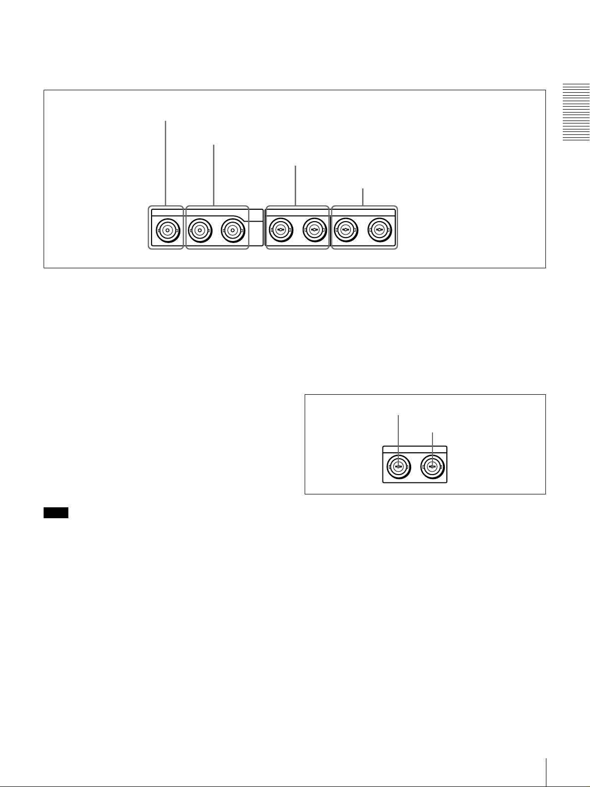
Rear Panel
a AC IN connector
Chapter 1 Overview
a
a AC IN connector
aa
d REF. VIDEO IN connectors
VIDEO
Y/CPST R-Y/C B-Y
IN
REF.VIDEO VIDEO OUT
IN
IN OUT1 OUT2
INTC OUT
D Time code input/output section
R-Y/C/CPST
Y/CPST
SDI/SDTI
(QSDI)
REMOTE
c REMOTE connector
Use the supplied power cord to connect this to an AC
outlet.
b
b DV IN/OUT connector (6-pin IEEE-1394)
bb
(optional DSBK-1503 i.LINK/DV Input/Output
Board)
This connector is avail able when the optional DSBK-1503
board is installed. It inputs and outputs digital video and
audio signals in DV format.
AC IN
(SUPER)
B-Y/CPST
IN
1/2 3/4 1/2 3/4
AUDIO OUT
MONITOR
AUDIO IN
1/3
1/3
OUTAUDIO I/O (AES/EBU)
(see page 21)
d
d REF. (reference) VIDEO IN connectors (BNC
dd
type)
Input a reference video signal. The two connectors are
loop-through connectors. You can connect the reference
video signal input to the left connector to ot her equipment
via the right connector (marked ). When no connection
is made to the right connector, the left connector is
terminated with an impedance of 75 Ω automatically.
2/4
2/4
DV IN/OUT
A Analog video/audio signal
input section
(see page 19)
B Analog video/audio signal
output section
(see page 20)
b DV IN/O UT connector
C Digital signal input/output
section
(see page 21)
Note
When searching at speeds in the range +1/2 to +1/30 or
1
−
/30 to −1/2 times normal speed, the audio signal output
from this connector and moni to re d on ext er na l equi pmen t
may sound differently from the audio signal played back
on this unit.
c
c REMOTE connector (D-sub 9-pin)
cc
When controlling this unit from an editing control unit
such as the ES-7, PVE-500, BVE-600/800/910, or RM450/450CE, connect the editing control unit to this
connector using the optional 9-pin remote control cable.
Location and Functio n of Parts
18
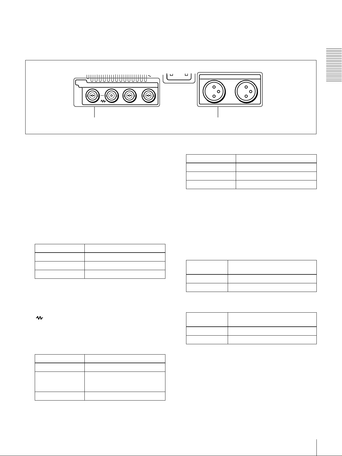
A Analog video/audio signal input section (optional DSBK-1504/1504P Analog Input
Board)
The connectors in this section are available when the
optional DSBK-1504/1504P board is installed.
AC IN
VIDEO
Y/CPST R-Y/C B-Y
IN
a VIDEO IN connectors b AUDIO IN 1/3 and AUDIO IN 2/4 connectors
a
a VIDEO IN connectors (BNC type)
aa
There are the following VIDEO IN connectors for
inputting analog video signals:
• Y/CPST (loop-through connectors)
• R−Y/C
• B−Y
The signals you can connect to these con nectors depend on
the selection made with the VIDEO button in the video/
audio input selection section. The selection is indicated by
the VIDEO indicators in the INPUT signal display section.
The analog video signals that can be input to these
connectors are as follows.
When COMPOSITE is selected:
AUDIO IN
1/3
2/4
When Y−−−−R,B is selected:
Connectors Input signals
Y/CPST Y signal
R−Y/C R−Y signal
B−YB−Y signal
b
b AUDIO IN 1/3 and AUDIO IN 2/4 connectors
bb
(XLR-3 pin, female)
Use these connectors to input analog audio signals from an
external video cassette player or other audio equipment.
The signals input to these connectors are recorded on the
audio channels determi ned by the current audio recording
mode, as follows.
Chapter 1 Overview
Connectors Input signals
Y/CPST Composite signal
R−Y/C — (not usable)
B−Y — (not usable)
The two Y/CPST connectors are loop-through
connectors. When using the signal input to the left Y/
CPST connector as a reference video signal, for
example, you can bridge-connect the signal to other
equipment via the right Y/CPST connector (marked
). When no connection is made to the right Y/
CPST connector, the left Y/CPST connector is
terminated with an impedance of 75 Ω automatically.
When S VIDEO is selected:
Connectors Input signals
Y/CPST Y signal
R−Y/C C signal
(3.58 MHz for DSR-1500/
4.43 MHz for DSR-1500P)
B−Y — (not usable)
When in 2 CH (48 kHz) mode:
Input
connectors
AUDIO IN 1/3 Audio channel 1
AUDIO IN 2/4 Audio channel 2
Audio channels on which input
signals are recorded
When in 4 CH (32 kHz) mode:
Input
connectors
AUDIO IN 1/3 Audio channels 1 and 3
AUDIO IN 2/4 Audio channels 2 and 4
Audio channels on which input
signals are recorded
You can switch the audio recording mode with the REC
MODE menu item (see page 65). The selection i s indicated
by the REC MODE display on the front panel.
Location and Function of Parts
19
B Analog video/audio signal output section
a VIDEO OUT connectors
b AUDIO OUT 1/3 and AUDIO OUT 2/4 connectors
Y/CPST R-Y/C/CPST
Chapter 1 Overview
a
a VIDEO OUT connectors (BNC type)
aa
VIDEO OUT
(SUPER)
B-Y/CPST
There are the following VIDEO OUT connectors for
outputting analog video signals:
• Y/CPST
• R−Y/C/CPST
• B−Y/CPST (SUPER)
The signals output from these connectors depend on the
setting of the VIDEO OUTPUT menu item (see page 67).
The setting is indicated by the VIDEO indicators in the
OUTPUT signal display section on the front panel.
The analog video signals that can be output from these
connectors are as follows.
When COMPOSITE is selected:
Connectors Output signals
Y/CPST Composite signal
R−Y/C/CPST Composite signal
B−Y/CPST
(SUPER)
Composite signal
When the CHARA. DISPLAY menu item (see page
60) is set to ON (fac tory default setting), the
CPST (SUPER) connector outputs a composite video
signal with superimp osed text information.
When S-VIDEO is selected:
Connectors Output signals
Y/CPST Y signal
R−Y/C/CPST C signal
B−Y/CPST
(SUPER)
(3.58 MHz for DSR-1500/
4.43 MHz for DSR-1500P)
Composite signal
When the CHARA. DISPLAY menu item (see page
60) is set to ON (fac tory default setting), the B−Y/
CPST (SUPER) connector outputs a composite video
signal with superimposed text information.
AUDIO OUT
MONITOR
c MONITOR connector
B−Y
/
1/3
2/4
When Y−−−−R, B is selected:
Connectors Output signals
Y/CPST Y signal
R−Y/C/CPST R−Y signal
B−Y/CPST
(SUPER)
b
b AUDIO OUT 1/3 and AUDIO OUT 2/4 connectors
bb
B−Y signal
(XLR-3 pin, male)
These connectors output anal og a udi o si gnal s. T he ou tp ut
audio channels are det ermined by the playback audio mode
and the setting (1/2 CH or 3/4 CH) of the AUDIO
OUTPUT menu item (see page 67) as follows.
When in 2 CH (48 kHz or 44.1 kHz) mode:
Output
connectors
AUDIO OUT 1/3 Audio channel 1 (when 1/2 CH is
AUDIO OUT 2/4 Audio channel 2 (when 1/2 CH is
Output audio channels
selected) or silent (when 3/4 CH is
selected)
selected) or silent (when 3/4 CH is
selected)
When in 4 CH (32 kHz) mode:
Output
connectors
AUDIO OUT 1/3 Audio channel 1 (when 1/2 CH is
AUDIO OUT 2/4 Audio channel 2 (when 1/2 CH is
Output audio channels
selected) or audio chann el 3 (w hen 3/
4 CH is selected)
selected) or audio chann el 4 (w hen 3/
4 CH is selected)
The current playback audio mode is indi cated by the PB Fs
display on the front panel.
c
c MONITOR connector (RCA phono jack)
cc
This connector outputs audio signals for monitoring. The
audio signals to be output from this connector can be
selected with the MONITOR SELECT button and
METER CH-1/2 3/4 button on the front panel.
Location and Functio n of Parts
20
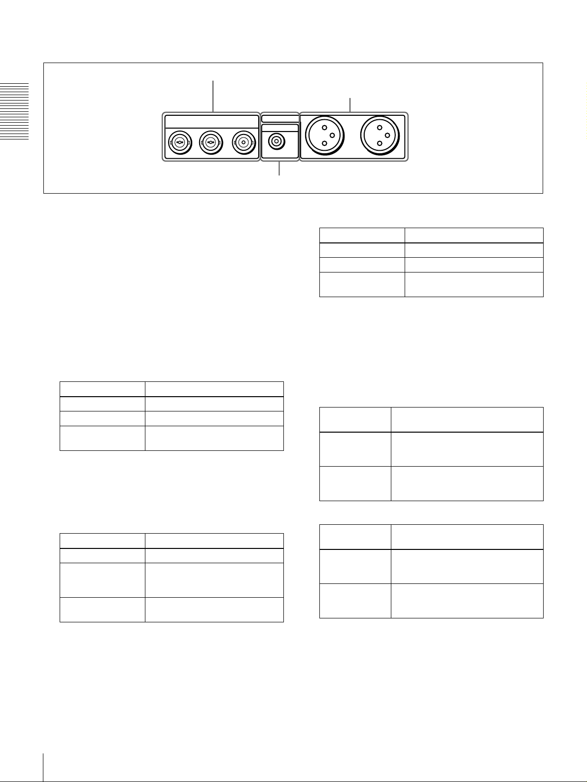
C Digital signal input/output section (optional DSBK-1501 Digital Input/Output Board)
The connectors in this section are available when the
optional DSBK-1501 board is installed.
a SDI/S DT I (QSDI) IN connec tor
b SDI/SDT I (QSDI) OUT1/OUT2 connectors
IN OUT1 OUT2 IN
a
a SDI/SDTI (QSDI) IN (Serial Digital Interface/
aa
SDI/SDTI
(QSDI)
1/2 3/4 1/2 3/4
Serial Data Transport Interface (QSDI) input)
connector (BNC type)
This connector inputs digital video and audio signals in
SDTI (QSDI) or SDI format. To select the required input
signal formats, use the SDTI/i.LINK button or VIDEO
button on the front panel. The current input signal
selections are indi cated in the INPUT signal display
section on the front panel.
b
b SDI/SDTI (QSDI) OUT1/OUT2 (Serial Digital
bb
Interface/Serial Data Transport Interface (QSDI)
output 1/output 2) connectors (BNC type)
These connectors output digi tal vide o and audio sign als in
SDTI (QSDI) or SDI form at. To select t hese out put si gnal
formats, use the DIGITAL OUTPUT menu item (se e page
67). The current output signal selections are indicated in
the OUTPUT signal display section on the front panel.
c AUDIO (AES/EBU) IN 1/2 and AUDIO (AES/EBU)
IN 3/4 connectors
d AUDIO (AES /EBU) O UT 1/2 and AUDIO
(AES/EBU) OUT 3/4 connectors
OUTAUDIO I/O (AES/EBU)
d
d AUDIO (AES/EBU) OUT 1/2 and AUDIO (AES/
dd
EBU) OUT 3/4 connectors (BNC type)
These connectors output di gital audio signals in AES/EBU
format.
The left connector (1/2) is f or audio ch annels 1 an d 2, and
the right connector (3/4) is for audio channels 3 and 4.
D Time code input/output section
a TC IN connector
b TC OUT connector
INTC OUT
Chapter 1 Overview
Note
When searching at speeds in the range +1/2 to +1/30 or
1
−
/2 to −1/30 times normal speed, the audio signal output
from these connectors in SDTI (QSDI) format and
monitored on external equipment may sound differently
from the audio signal played back on this unit.
c
c AUDIO (AES/EBU) IN 1/2 and AUDIO (AES/
cc
EBU) IN 3/4 connectors (BNC type)
Input digital audio signals in AES/EBU format to these
connectors.
The left connector (1/2) is for audio cha nnels 1 and 2, and
the right connector (3/4) is for audio channels 3 and 4.
a
a TC IN (time code input) connector (BNC type)
aa
Input externally generated SMPTE time code (for DSR-
1500) or EBU time code (for DSR-1500P) to this
connector.
b
b TC OUT (time code output) connector (BNC type)
bb
This connector outputs a time code according to the
operating state of the unit, as follows:
During playback: the playback time code
During recording: the time code generated by the internal
time code generator o r the time code input to the TC
IN connector. When the EE OUT PHASE menu item
(see page 63) is set to MUTE, no time code is output.
Location and Function of Parts
21

Chapter 1 Overview
Location and Functio n of Parts
22
Recording and Playback
Usable Cassettes
This unit can use the DVCAM cassettes listed below.
Model name Size
PDV-64ME/94ME/124ME/184ME Standard size
PDVM-12ME/22ME/32ME/40 ME Mini size
The numbers in each model name indicate the maximum recording/playback
time (in minutes) for each model. For example, the PDV-184ME has a
maximum recording/playback time of 184 minutes.
Cassettes usable for playback only
All consumer DV cassettes and large- and medium-size DVCPRO (25 Mbps)
cassettes are usable for playback only.
Notes
• If you insert an incorrect type of cassette, it will be automatically ejected.
• When operating this unit as a player, you can also use DV cassettes on the
unit. However, it is the best choice to always use DVCAM cassette s because
they are more reliable than DV cassettes whatever your purpose may be:
playback, editing, or long-period storage of recordings.
• Cassettes that have been recorded by a DV-format recorder can be played
back on this unit but cannot be used for reco rding a t editing oper ati on. When
you insert such a cassette into this unit, the NO EDIT indica tor lights up in the
display section on the front panel of this unit.
Chapter
2
Usable Cassettes
23
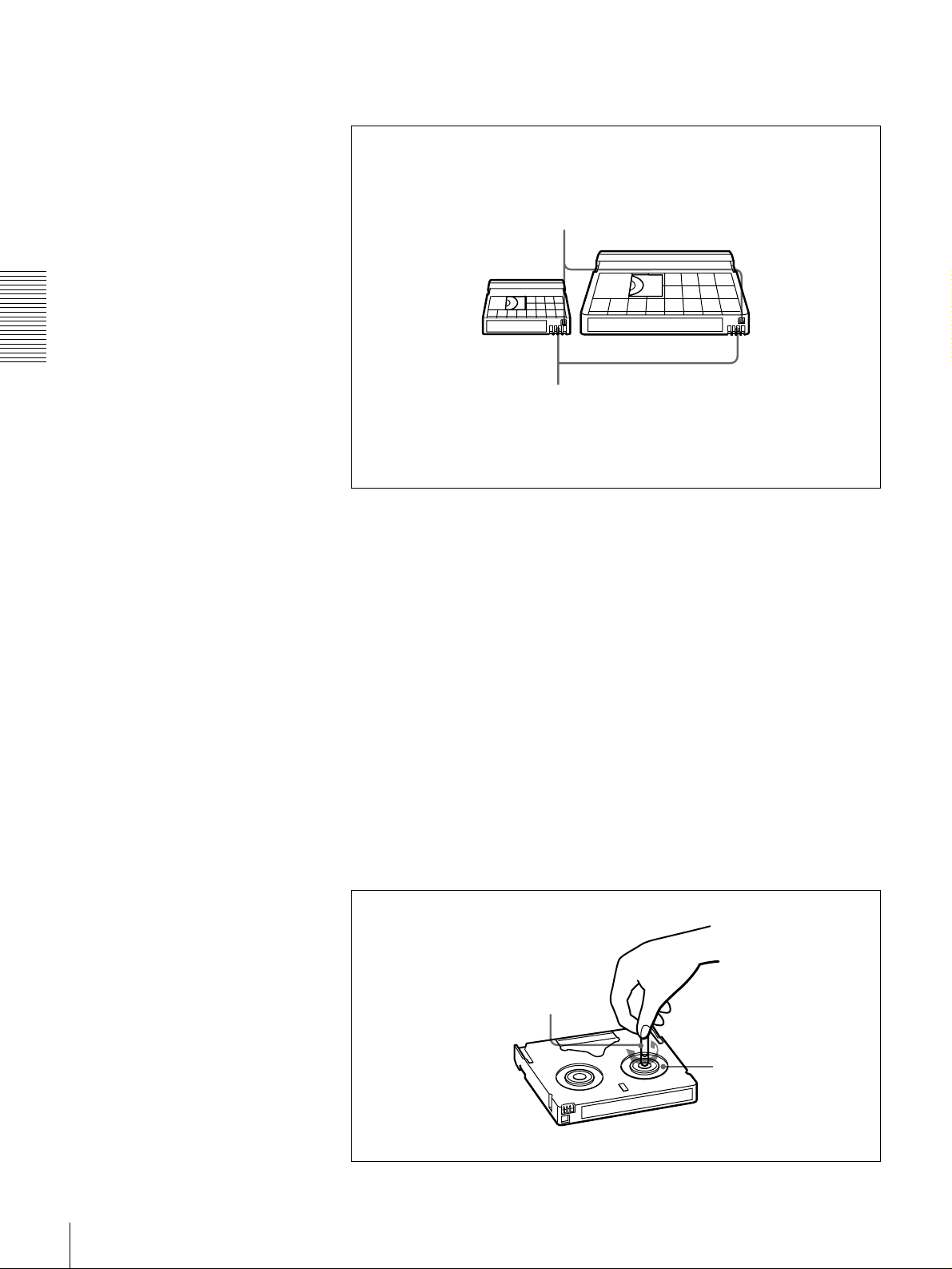
D VCA M ca sse t te s
Chapter 2 Recording and Play back
Notes on using cassettes
The following figure illustrates the DVCAM cassettes.
REC/SAVE switch
For details of this switch, see “Preventing accidental
erasure” on page 25.
Mini size Standard size
Cassette memory
This memory is used to store ClipLink log data.
For details of ClipLink log data, see the appendix
“ClipLink Guide” (page 105).
• Before storing the cassette for a long period of time, rewind the tape to the
beginning and be sure to put t he cassette in its st orage case, preferab ly on end
instead of flat on its side.
Storing a cassette in any other condition (not rewound, out of its case, etc.)
may cause the video and audio contents to become damaged over time.
• If the cassette memory connector (contact point) becomes dirty, connection
problems may occur, causing a loss of functions. Remove away any dust or
dirt from this area before using the cassette.
• If the cassette is dropped on th e floor or ot herwise re ceives a hard impa ct, the
tape may become slackened and may not record and/or play back correctly.
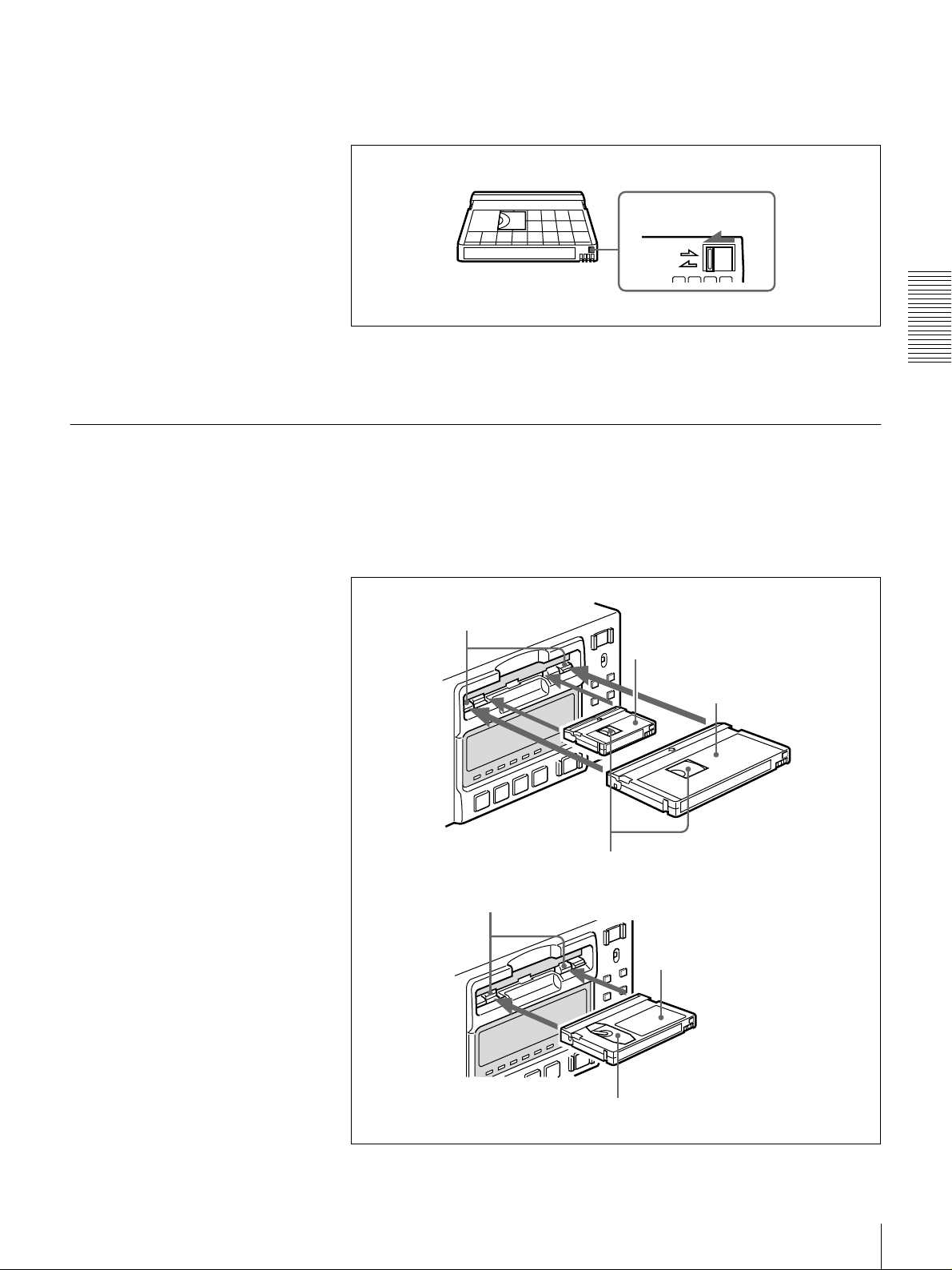
Checking the tape for slack
For information about how to check the tape for slack, see the next section.
Using a paper clip or a similar o bject, turn th e reel gently in the di rection shown
by the arrow. If the reel does not move, there is no slack . Insert the cassette into
the cassette compartment, and after about 10 seconds take it out.
Paper clip, etc.
Reel
24
Usable Cassettes
Preventing accidenta l erasure
Set the REC/SAVE switch on the cassette to SAVE to prevent accidental
erasure of recorded contents.
To enable re-recording
Set the REC/SAVE switch to REC.
When this switch is set to SAVE, the u nit cannot record on the tape.
Inserting and Ejecting Cassettes
Inserting a cassette
This unit accepts three sizes of cassette: L (standard size), M (medium size:
DVCPRO) and S (mini size). When inserting a cassette in the unit, make sure
its tape window faces upward as shown in the following figure.
REC/SAVE switch
Set to SAVE
REC
SAVE
Chapter 2 Recording and Play back
Outer guides
Inner guides
Mini size (Insert the cassette into the
middle of the cassette compartment.)
Standard size
Tape window facing upward
Medium size (Align the cassette with
the outer guides, then slide it in over
the inner guides.)
Tape window facing upward
Usable Cassettes
25
No double insertion of cassettes
Ejecting a cassette
Chapter 2 Recording and Play back
When you insert a cassette, the orange lock-out plate appears in the cassette
compartment to prevent double insertion.
Press the EJECT button.
EJECT button
OVER
OVER
dB
dB
INPUT
0
0
AUDIO
VIDEO
V:SDTI
COMPOSITE
CH-1 1/2
CH-2 3/4
SDTI
ANALOG
ANALOG
S VIDEO
-12
-12
i.LINK
AES/EBU
AES/EBU
Y-R,B
-20
-20
SDI SG
SDI SG SDI SG
OUTPUT
-30
-30
AUDIO
VIDEO
-40
-40
SDI
COMPOSITE
CH 1/2
-60
-60
SDTI
S VIDEO
CH 3/4
CH-
CH-
2 4
1 3
Y-R,B
REW PLAY F FWD STOP REC
REC INHI
SERVO
U-BIT
TC NOCLEDIT
HOURS MINUTES SECONDS FRAMES
PB F
S
REC MODE
VITC
48K 44.1K 32K
2CH 4CH
EDIT MODE
REPEATCOUNTER
REMOTE
9P i.LINK
26
Usable Cassettes
Recording
Settings for Recording
This section describes the necessary settings and operations to perform
recording on this u ni t. The same settings and operat i ons a ppl y whether you are
using the unit as part of an editing system, for dubbing, or as a stand-alone
recorder.
For the necessary connections for recording and t he settings not covered in this
section, see Chapter 5 “Connections and Settings.”
For dubbing of SDTI (QSDI) format signals, use the AUTO FUNCT ION menu
item SDTI DUBBING (see page 71). For details, see “Digitally Dubbing
Signals in DVCAM Format” on page 51.
Chapter 2 Recording and Play back
Note
When using the unit as a recorder, the opti onal boards corresponding to the in put
signal formats to be used are required.
For details about the optional boards, see “Optional Accessories” (page 7).
1
Video monitor
Recorder (DSR-1500/1500P)
3
7
OVER
OVER
OVER
OVER
dB
dB
dB
dB
dB
dB
dB
dB
0
0
0
0
0
0
0
0
1
1
1
1
-12
-12
-12
-12
0
0
0
0
-20
-20
-20
-20
-1
-1
-1
-1
-30
-30
-30
-30
-40
-40
-40
-40
-2
-2
-2
-2
PB FS
-60
48k44.1k32k
-60
-60
-60
1
2
3
4
OVER
OVER
dB
dB
INPUT
0
0
VIDEO
V:SDTI
COMPOSITE
SDTI
S VIDEO
-12
-12
i.LINK
-20
-20
SDI SG
OUTPUT
-30
-30
VIDEO
-40
-40
SDI
COMPOSITE
-60
-60
SDTI
S VIDEO
CH-
CH-
2 4
1 3
REW PLAY F FWD STOP REC
Audio level meters
Player (DSR-1600/1600P, etc.)
INPUT signal display
section
LOCAL/REMOTE
switch
REC INHI
SERVO
U-BIT
AUDIO
CH-1 1/2
CH-2 3/4
ANALOG
ANALOG
AES/EBU
AES/EBU
Y-R,B
SDI SG SDI SG
AUDIO
CH 1/2
CH 3/4
Y-R,B
TC NOCLEDIT
HOURS MINUTES SECONDS FRAMES
PB FS
48K 44.1K 32K
REPEATCOUNTER
REC MODE
VITC
REMOTE
9P i.LINK
2CH 4CH
EDIT MODE
2
6
4
5
When controlling this unit from an editing control unit connected to the
REMOTE connector, see “LOCAL/REMOTE switch” on page 9 and the
description of the REMOTE I/F menu item on page 67.
Recording
27
1
Power on the video monitor, then set its input switches according to the
signals input from this unit.
2
Set up the player to play back a tape.
For details, refer to the operating instructions for the player.
3
Power on this unit by pressing on the side of the POWER switch.
4
When the REMOTE indicator is off (the external editing control unit is not
used), use the COUNTER SELECT button to select the type of time data to
be used.
Each press of this button cycles through three options: COUNTER (CNT
value), TC (time code), and U-BIT (user bit data). The time data type
indicator for each option lights as it is selected.
Chapter 2 Recording and Play back
Selected time data Time data type indicator
Count value of the time counter COUNTER
Time code TC
User bit data U-BIT
When the REMOTE indicator is lit, selection of the time data type is carried
out at the editing control unit.
5
Select the formats of video and audio input signal to be recorded.
Use the INPUT SELECT buttons in the vi deo/audi o input settin g section to
select the desired signal formats. Each selection is shown by a lit indicator
in the INPUT signal display section.
Video input signal
(input connector)
Composite signal
(VIDEO IN: Y/CPST)
Separated Y/C signal
(VIDEO IN: Y/CPST and
R−Y/C)
Component signal
(VIDEO IN: Y/CPST,
R−Y/C, and B−Y)
SDI signal
(SDI/SDTI (QSDI) IN)
SDTI (QSDI) signal
(SDI/SDTI (QSDI) IN)
i.LINK-compatible digital
video signal in DV format
(i.D V IN/O UT)
Internal test video signal VIDEO SG in VIDEO group
a) The indicators without the corresponding optional boards (DSBK-1501/1503/1504/1504P)
installed in the unit do not light.
Corresponding INPUT
SELECT button
VIDEO COMPOSITE in VIDEO
VIDEO S VIDEO in VIDEO
VIDEO Y−R,B in VIDEO group
VIDEO SDI in VIDEO group
SDTI/i.LINK SDTI: both SDTI video
SDTI/i.LINK i.LINK
Lit indicator in the
INPUT signal display
section
group
group
V:SDTI: only SDTI video
a)
and audio input
signals are
recorded.
input signal is
recorded.
28
Recording
Audio input signal
(input connector)
Analog signal
(AUDIO IN 1/3 and
AUDIO IN 2/4)
AES/EBU signal
(AUDIO (AES/EBU) IN)
SDI signal
(SDI/SDTI (QSDI) IN)
SDTI (QSDI) signal
(SDI/SDTI (QSDI) IN)
i.LINK-compatible digital
audio signal i n DV format
(i.D V IN/O UT)
Internal test audio signal CH1 1/2 and CH2 3/4 SG in AUDIO group
a) The indicators without the corresponding optional boards (DSBK-1501/1503/1504/1504P)
installed in the unit do not light.
Caution
Corresponding INPUT
SELECT button
CH1 1/2 and CH2 3/4 ANALOG in AUDIO
CH1 1/2 and CH2 3/4 AES/EBU in AUDIO
CH1 1/2 and CH2 3/4 SDI in AUDIO group
SDTI/i.LINK SDTI
SDTI/i.LINK i.LINK
Lit indicator in the
INPUT signal display
section
group
group
a)
Once you have started recording, you cannot change the input signal
selection.
Chapter 2 Recording and Play back
6
Select the audio mode.
Select either two-channel mode (2 CHANNEL) or four-channel mode (4
CHANNEL) with the REC MODE menu item (see page 65). The
corresponding indicator lights in the REC MODE display.
Audio mode Lit indicator in the REC MODE display
2-channel mode 2CH
4-channel mode 4CH
Cautions
• In the DVCAM format, there are two audio recording modes, with either
two channels at 48 kHz or four channels at 32 kHz. It is not possible to
select other modes (for example with four channels at 48 kHz).
• During audio editing, if a signal used in assemble or insert editing is in a
different mode from the b ase tape, the signal s will be discon tinuous at the
edit points, and correct edit ing will not be obtaine d. For this reason, audio
editing between different modes is inhibited on this unit.
For smooth editing operations, check the audio recording mode of the
base tape beforehand.
• Once you have started recording, you cannot change the audio mode
selection.
• If on a tape there is a point where the audio mode is switched, it is not
possible to carry out insert editing over a section including that point.
• When, in 4-channel mode, analog audio is selected for all four channels
(channels 1/2 and 3/4), the same analog audio signals are recorded on
channels 1 and 3 and on channels 2 and 4, respectively.
Recording
29
Recor ding Procedure
Chapter 2 Recording and Play back
7
With the VAR switch on th e front panel set to REC, use the REC/P B
LEVEL control knob s to adjust audi o input levels. Watching the au dio level
meter, adjust the level so that the meter does not indicate higher values than
0 dB when the audio signal is at its maximum. When the level exceeds 0 dB,
the OVER indicator lights.
The factory-preset audio recording level is −20 dB (DSR-1500) or −18 dB
(DSR-1500P). This setting can be changed using the LEVEL SELECT
menu item (see page 66).
This section describes the procedure t o perform recor ding on th is unit, showing
an example session in which playback signals coming from a player VCR will
be recorded on the tape loaded in the unit.
1
LOCAL/REMOTE
OVER
OVER
dB
dB
INPUT
0
0
V:SDTI
-12
-12
-20
-20
OUTPUT
-30
-30
-40
-40
-60
-60
CH-
CH-
2 4
1 3
REW PLAY F FWD STOP REC
VIDEO
COMPOSITE
SDTI
S VIDEO
i.LINK
Y-R,B
SDI SG
VIDEO
SDI
COMPOSITE
SDTI
S VIDEO
Y-R,B
SERVO
U-BIT
AUDIO
CH-1 1/2
CH-2 3/4
TC NOCLEDIT
ANALOG
ANALOG
AES/EBU
AES/EBU
SDI SG SDI SG
AUDIO
HOURS MINUTES SECONDS FRAMES
CH 1/2
CH 3/4
PB FS
48K 44.1K 32K
REC MODE
2CH 4CH
REC INHI
REPEATCOUNTER
VITC
REMOTE
9P i.LINK
EDIT MODE
switch
Recorder
(DSR-1500/1500P)
2
OVER
OVER
OVER
OVER
dB
dB
dB
dB
dB
dB
dB
dB
0
0
0
0
0
0
0
0
-12
1
-12
1
-12
1
-12
1
-20
0
-20
0
-20
0
-20
0
-1
-1
-1
-1
-30
-30
-30
-30
-40
-40
-40
-40
-2
-2
-2
-2
PB FS
-60
1
Player
(DSR-1600/1600P, etc.)
Notes
• When controlling this unit from an editing control unit connected to the
REMOTE connector of this unit, set the LOCAL/REMOTE switch to
REMOTE, turning the REMOTE indicator on. When not, set the switch to
LOCAL, turning the in dicator off.
• If you intend to use a tape recorded on this unit i n a system comprising a DSR85/85P and an ES-7 Edi tStati on, i t is re commended t o re cord c olor bars on a t
least the first 40 seconds of the tape.
When transferring digital signals from the DSR-85/85P to the ES-7
EditStation at fou r times normal speed, there must be recording for
approximately 40 seconds before the IN point.
48k44.1k32k
-60
-60
-60
2
3
4
3
30
Recording
 Loading...