

Page 1

Digital
Videocassette
Recorder
3-065-956-11(1)
Operating InstructionsMode d'emploi ____
DSR-11
© 2000 Sony Corporation
Page 2
WARNING
To prevent fire or shock hazard, do not
expose the unit to rain or moisture.
CAUTION
RISK OF ELECTRIC SHOCK
DO NOT OPEN
CAUTION TO REDUCE THE RISK OF ELECTRIC SHOCK,
DO NOT REMOVE COVER (OR BACK)
NO USER SERVICEABLE PARTS INSIDE
REFER SERVICING TO QUALIFIED SERVICE PERSONNEL
This symbol is intended to alert the user to the
presence of uninsulated "dangerous voltage"
within the product's enclosure that may be of
sufficient magnitude to constitute a risk of
electric shock to persons
This symbol is intended to alert the user to the
presence of important operating and
maintenance (servicing) instructions in the
literature accompanying the appliance
The AC adaptor must be changed only at qualified service
shop
The nameplate of the AC adaptor is located on its bottom
For customers in Europe
This product with the CE marking complies with both the
EMC Directive (89/336/EEC) and the Low Voltage Directive
(73/23/EEC) issued by the Commission of the European
Community
Compliance with these directives implies conformity to the
following European standards
• EN60065 Product Safety (supplied AC adaptor)
• EN55103-1 Electromagnetic Interference (Emission)
• EN55103-2 Electromagnetic Susceptibility (Immunity)
This product is intended for use in the following
Electromagnetic Environments)
E1 (residential), E2 (commercial and light industrial), E3
(urban outdoors) and E4 (controlled EMC environment, ex
TV studio)
Owner's record
The model number is located at the rear and front of the unit
and the serial number on the rear Record the serial number
in the space provided below Refer to these numbers
whenever you call upon your Sony dealer regarding this
product
Model No DSR-11
For customers in the U.S.A.
If you have any questions about this product, you may
call: Sony's Business Information Center (BIC) at 1-800-
686-SONY (7669)
or Write to: Sony Customer Information Services Center
Trade Name.
Model
Responsible Party:
Address.
Telephone Number
This device complies with Part 15 of the FCC Rules
Operation is subject to the following two conditions (1)
This device may not cause harmful interference, and (2)
this device must accept any interference received,
including interference that may cause undesired
operation
Serial
6900-29 Daniels Parkway, PMB 330 Fort
Myers, Florida 33912
Declaration of Conformity
No.
_______________
SONY
DSR-11
Sony Electronics Inc
1 Sony Drive, Park Ridge,
NJ 07656 USA
201-930-6972
For the customers in the Netherlands
Voor de klanten in Nederland
BI) dit product zijn batterijen
geleverd Wanneer deze leeg
zi]n, moet u ze met weggooien
maar inleveren als KCA
2
Page 3
CAUTION
Precautions
You are cautioned that any changes or modifications not
expressly approved in this manual could void your authority
to operate this equipment.
Note
This equipment has been tested and found to comply with
the limits for a Class B digital device, pursuant to Part 15 of
the FCC Rules. These limits are designed to provide
reasonable protection against harmful interference in a
residential installation. This equipment generates, uses, and
can radiate radio frequency energy and, if not installed and
used in accordance with the instructions, may cause harmful
interference to radio communications. However, there is no
guarantee that interference will not occur in a particular
installation. If this equipment does cause harmful
interference to radio or television reception, which can be
determined by turning the equipment off and on, the user is
encouraged to try to correct the interference by one or more
of the following measures:
• Reorient or relocate the receiving antenna.
• Increase the separation between the equipment and
receiver.
• Connect the equipment into an outlet on a circuit different
from that to which the receiver is connected.
• Consult the dealer or an experienced radio/TV technician
for help.
For customers in the U.S.A. and CANADA
CAUTION
• Do not damage the power cord and AC adaptor.
•Use only the supplied power cord and supplied AC
adaptor.
• Do not use the unit in an environment that is subject
to excessive soot, steam, humidity or dust.
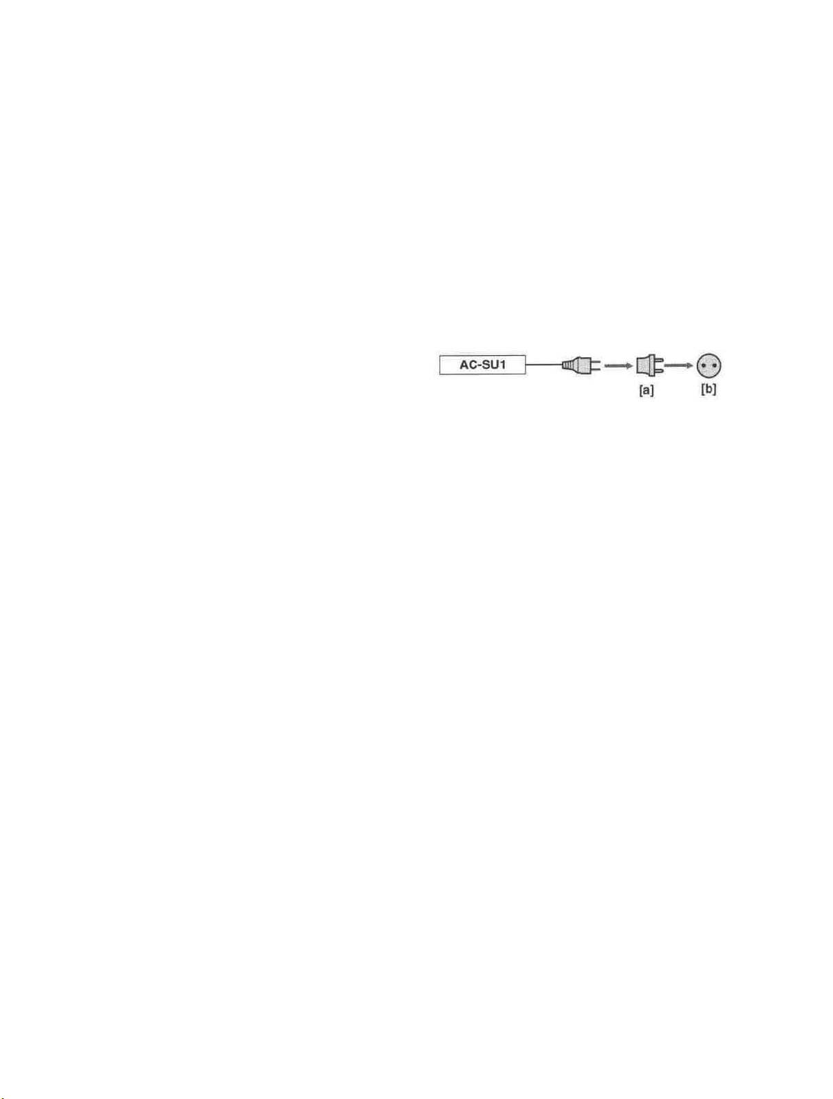
You can use this equipment in any country or area with
the AC power adaptor supplied with this unit within
100 V to 240 V AC, 50/60 Hz.
Use a commercially available AC plug adaptor [a], if
necessary, depending on the design of the wall outlet
lb].
The AC adaptor is not intended to be serviced. Should
the product cease to function in its intended manner, it
should be returned to the manufacturer or be discarded.
On installing
The unit is equipped with ventilation holes on the rear.
Do not block or place anything near these holes, or
internal heat build-up may occur, causing damage to
the unit.
TO PREVENT ELECTRIC SHOCK, MATCH WIDE BLADE
OF PLUG TO WIDE SLOT, FULLY INSERT.
Caution
Television programs, films, video tapes and other materials
may be copyrighted. Unauthorized recording of such material
may be contrary to the provisions of the copyright laws. Also,
use of this recorder with cable television transmission may
require authorization from the cable television transmission
and/or program owner.
On repacking and shipping
Save the original shipping carton and packing material;
they will come in handy if you ever have to ship your
unit. For maximum protection, repack your unit as it
was originally packed at the factory, and take care not
to impart violent shocks in transit.
3
Page 4
Overview
Features
...............................................................
DVCAM Format....................................................
6
6
Playback and
Recording
Other Features ......................................................
Location and Function of Parts ..........................
Front Panel
Rear Panel ............................................................
Supplied Remote Commander .............................
Notes
on Video Cassettes
Preparations
Power Preparations................................................
Inserting/Ejecting Cassettes
Notes on Recording/Playback
Playback
Connections for Playback......................................
Settings for Playback.............................................
Playback Procedure
Playback Functions
...........................................................
...................................
.........................................................
..................................
...............................
................................................................
...............................................
...............................................
7
8
11
13
15
17
17
17
19
20
20
23
24
25
Adjusting and
Setting Through
Menus
Recording
.............................................................
Connections for Recording....................................
Settings for Recording ...........................................
Recording Procedure
Installing
the Unit Vertically
Operating the
Menu Organization
Menu Contents
Menus
.............................................
................................
.....................................
.........................................
...............................................
34
34
37
39
40
41
42
43
4 Table of Contents
8
Page 5

Maintenance
Troubleshooting..................................................
Alarm
Messages
..................................................
50
51
Notes
on Use
.......................................................
Compatibility of DVCAM and DV Format..........
Specifications......................................................
Glossary..............................................................
Index.....................................................................
52
55
58
60
61
Table of Contents 5
Page 6
Overview
Chapter
1
The DSR-11 is a '/4-inch digital video cassette recorder
that uses the DVCAM™ digital recording format. This
system achieves stable, superb picture quality by
digitally processing video signals that are separated
into color difference signals and luminance signals
(component video).
With a compact, lightweight and space-saving case,
the unit can be installed vertically and is equipped with
an analog interface as well as a digital interface
enabling connection to a digital device such as a
computer.
The DSR-11 's main features are described below.
DVCAM Format
DVCAM is based on the consumer DV format, which
uses the 4:1:1 component digital format (NTSC) or the
4:2:0 format (PAL), and provides a '/4-inch digital
recording format for professional use.
High picture quality, high stability
Video signals are separated into color difference
signals and luminance signals, which are encoded and
compressed to one-fifth size before being recorded to
ensure stable and superb picture quality.
Because the recording is digital, multi-generation
digital dubbing can be performed with virtually no
deterioration of quality.
Wide track pitch
The recording track pitch is 15 urn, fully 50 percent
wider than the DV format's 10-um track pitch. Thanks
to this feature, the DVCAM format sufficiently meets
the reliability and precision requirements of
professional editing.
High-quality PCM digital audio
PCM recording makes for a wide dynamic range and a
high signal-to-noise ratio, thereby enhancing sound
quality.
There are two recording modes: 2-channel mode (48-
kHz sampling and 16-bit linear code), which offers
sound quality equivalent to the DAT (Digital Audio
Tape) format, or 4-channel mode (32-kHz sampling
and 12-bit nonlinear code).
DV format compatibility
A DV cassette recorded on a DV-format VCR can be
played back on the unit (SP mode only). The unit can
also record in DV format (SP mode only). (Recording/
playing back an image in LP mode is not available.)
6 Chapter 1 Overview
Page 7

NTSC/PAL systems compatible
Jog audio function
The unit is compatible with NTSC and PAL systems.
When inputting the signals to the DV IN/OUT
connector or playing back a tape, the color system of
signals is detected automatically. The color system
select switch on the unit allows input of analog video
signals in either color system. This compatibility
allows you to record (download) or play back (upload)
both NTSC and PAL formatted signals with your
VCR, computer, or other equipment.
However, the unit cannot convert the color system of
the signals.
Choice of two cassette sizes
The unit can use both standard-size and mini-size
DVCAM or DV cassettes.
• According to cassette size, the position of the reel
drive plate changes automatically.
• The maximum recording/playback times are 184
minutes for standard size cassettes and 40 minutes for
mini-size cassettes (DVCAM format).
If you use the optional remote control unit DSRM-20,
audio can be monitored at various playback speeds
when in jog mode.
Other Features
Compact and can be installed vertically
The unit is compact and can be installed vertically.
With non-linear editing system, you can save space by
installing it vertically beside your computer.
Menu system for functionality and
operation settings
The unit provides a menu system to make its various
functions easier to use and set up.
Remote control
The unit can be operated by remote control from a
CONTROL-S system remote control unit, the DSRM20 (not supplied).
High-speed search function
When you use an editing controller or the optional
remote control unit (DSRM-20), the unit has a picture
search function that allows you to view color picture at
playback speeds up to 14 times (NTSC) or up to 17
times (PAL) normal speed in forward and reverse
directions. You can also search frame-by-frame in jog
mode.
You can also hear playback audio.
Digital slow playback
The unit has a frame memory function that allows
smooth, slow playback. This is available only at +'/3time speed and -'/3-time speed.
Superimposition function
Time code, operation mode indications, menus, error
messages, and other text data can be superimposed and
output in analog video signals.
Easy maintenance functions
• Self-diagnostics/alarm functions: The system
automatically detects an invalid operation, an invalid
connection or a malfunction, and outputs a
description, a cause and a recovery method as a
message superimposed on analog video signals.
• Digital hours meter: A digital hours meter counts
four types of time data—operating time, drum
rotation time, tape running time, and tape threading/
unthreading. The digital hours data is displayed in the
menu.
Chapter 1 Overview 7
Page 8
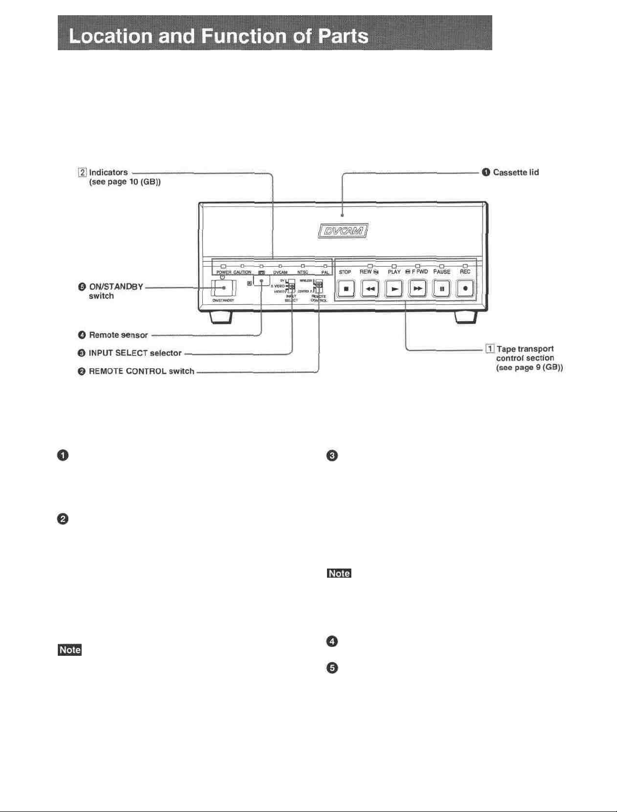
Front Panel
Cassette lid
To insert/eject a cassette, open the lid.
For details of usable cassettes, see "Notes on Video
Cassettes " on page ]5 (GB).
REMOTE CONTROL switch
Selects whether the unit is operated from the Remote
Commander or from an optional remote control unit.
WIRELESS: The unit is operated from the Remote
Commander.
CONTROL S: The unit is operated from a remote
control unit (the DSRM-20, not supplied),
connected to the CONTROL S jack on the rear
panel.
You can operate this unit from its front panel
regardless of this switch setting.
INPUT SELECT selector
You can select DV, S VIDEO, or VIDEO to input the
signals.
DV: Signal input from the DV IN/OUT connector
S VIDEO: Signal input from the S VIDEO connector
on INPUT jacks
VIDEO: Signal input from the VIDEO jack on
INPUT jacks
Do not change the selector setting during recording.
Otherwise, noise is output to the picture and sound and
that portion will not be recorded properly.
Remote sensor
ON/STANDBY switch
8 Chapter 1 Overview
Page 9
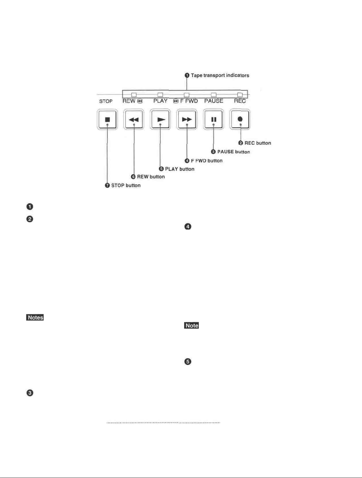
[1] Tape transport control section
Tape transport indicators
REC (record) button
When you press the PLAY button while holding down
this button, the indicator lights and recording begins.
To set the unit to recording pause mode, press the
PAUSE and PLAY buttons while holding down this
button. If you press only this button when the unit is in
the stop mode and the DV IN TC on the OTHERS
menu is set to EXTERNAL, the REC indicator lights
and you can also check the EE signals for time code.
After checking them, press the STOP button.
For details on the OTHERS menu, see "OTHERS menu" on
page 49 .
• The unit cannot record in the LP mode of the
consumer DV format. Only recording in the SP mode
is available.
• To set the unit to recording pause mode with the
remote control unit (DSRM-20, not supplied), press
the PAUSE button while holding down the PLAY
button to set the unit to the playback pause mode,
then press the REC button on the DSRM-20.
PAUSE button
Press this button to set the unit to pause mode while
recording or playing. Pressing this button again
resumes the operation. The indicator lights when the
unit is in pause mode.
F FWD (fast forward) button
When you press this button, the indicator lights and the
tape is fast forwarded. During fast forward, the picture
does not appear on the monitor (you can see the picture
as it is seen in the EE mode'' during fast forward).
To locate a scene while monitoring the picture, keep
pressing this button during fast forward, playback or in
playback pause mode (picture search).
You can change the tape transport mode in FF/REW
SPD on the VTR SET menu.
For details on the VTR SET menu, see "VTR SET menu" on
page 43 .
If you set the FF/REW SPD on the VTR SET menu to
SHUTTLEMAX, you can display the picture while
fast-forwarding the tape.
PLAY button
When you press this button, the indicator lights and
playback begins.
If you press this button while holding down the REW
button during stop, the tape is rewound to its beginning
and starts playing automatically (during rewind, the
REW indicator lights and the PLAY indicator flashes).
1) EEmode
"EE" stands for "Electric to Electric". In this EE mode, the
video and audio signals that are input to the VCR'S
recording circuitry do not pass through any magnetic
conversion circuits but instead are output via electric circuits
only. This mode is used to check the input signals and adjust
input levels. The pictures output in EE mode are referred to ,
as; F.F nicturps
Chapter 1 Overview
9
Page 10
Location and Function of Parts
• When the unit is playing back a part of the tape where
the recording format has been changed between the
DVCAM format and the DV format, the picture and
sound may be distorted.
• The unit cannot play back a tape recorded in the LP
mode of the consumer DV format.
button during stop, the tape is rewound to its beginning
and starts playing automatically (during rewind, the
REW indicator lights and the PLAY indicator flashes).
You can change the tape transport mode in FF/REW
SPD on the VTR SET menu.
For details on the VTR SET menu, see "VTR SET menu" on
page 43
REW (rewind) button
When you press this button, the indicator lights and the
tape starts rewinding. During rewind, the picture does
not appear on the monitor (you can see the picture as it
is seen in the EE mode during rewind).
To locate a scene while monitoring the picture, keep
pressing this button during rewind, playback or in
playback pause mode (picture search).
If you press the PLAY button while holding down this
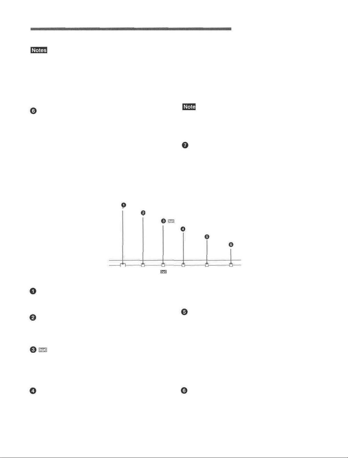
[2] Indicators
POWER indicator
CAUTION indicator
POWER CAUTION DVCAM
If you set the FF/REW SPD on the VTR SET menu to
SHUTTLEMAX, you can display the picture while
rewinding the tape.
STOP button
Press this button to stop the current tape transport
operation.
indicator
DVCAM indicator
NTSC indicator
PAL indicator
NTSC
PAL
POWER indicator
Lights in green when the power of this unit is on and
lights in red when the unit is in the standby mode.
CAUTION indicator
Flashes when an error occurs.
For details on cautions, see "Alarm Messages" on page
51
(cassette) indicator
Lights when a digital video cassette is loaded. Even
if the unit is in the standby mode, the indicator lights
as long as the cassette is inside of the unit. While the
cassette is being ejected, the indicator flashes.
DVCAM indicator
Lights when the unit is playing back a tape recorded
in DVCAM format.
When the REC MODE on the VTR SET menu is set
to DVCAM, this indicator also lights during
recording or in the EE mode.
10
Chapter 1 Overview
For details on the VTR SET menu, see "VTR SET menu" on
page 43 (GB).
NTSC indicator
Lights when:
• the unit is in the EE mode, analog video signals are
input and the NTSC/PAL select switch is set to
NTSC.
• the unit is in the EE mode and NTSC formatted
video signals are input from the DV IN/OUT
connector.
• a tape that has NTSC formatted video signals is
being played back.
PAL indicator
Lights when:
• the unit is in the EE mode, analog video signals are
input and the NTSC/PAL select switch is set to PAL.
• the unit is in the EE mode and PAL formatted video
signals are input from the DV IN/OUT connector. •
• a tape that has PAL formatted video signals is being
played back.
Page 11
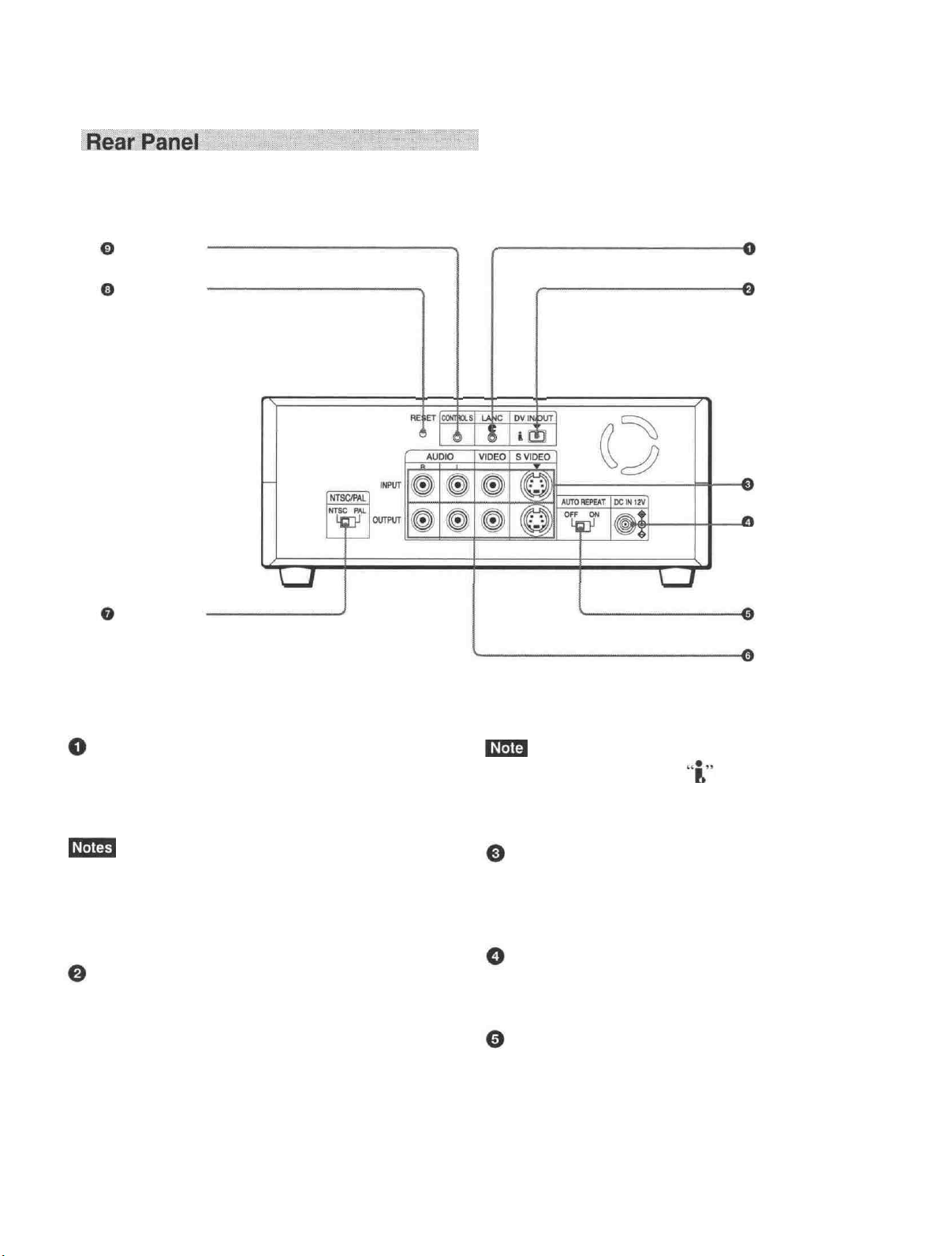
CONTROL S
jack
RESET button
LANC jack
DV IN/OUT
connector
INPUT jacks
DC IN 12V
connector
NTSC/PAL
select switch
Connects to other video devices that have a LANC
jack. You can operate the unit from other video
devices.
• You cannot operate the ejection of a cassette from a
device connected to the LANC jack.
• The LANC jack on the unit has only LANC-S
functions. The unit has no LANC-M functions.
DV IN/OUT connector (4-pin)
Used to input/output a digital signal that complies with
the i.LINK standard (Recommended cable: VMCIL4415(A),VMC-IL4615(A)). Use when an external
device which you want to connect to the unit has a DV
jack. If you connect the unit and the other device using
DV jacks, you can minimize deterioration of picture
quality during recording, dubbing or capturing still
pictures into a personal computer by digital
processing. For details, refer to the instruction manual
of the equipment you use.
AUTO REPEAT
switch
OUTPUT jacks
i.LINK and the i.LINK logo are trademarks and
indicate that this product is in agreement with IEEE
1394-1995 specifications and their revisions.
INPUT jacks
Used to input analog video and audio signals. To
connect a VCR equipped with S-video output, use the
S VIDEO connector on the unit.
DC IN 12V connector
AUTO REPEAT switch
Used to repeat the playback of all or a part of the tape.
For details on the auto repeat function, see "Auto Repeat"
on page 32 .
Chapter 1 Overview 11
Page 12

Location and Function of Parts
OUTPUT iacks
Used to output analog video and audio signals. To
connect a VCR equipped with S-video input, use the S
VIDEO connector on the unit.
• Various text data are superimposed and output from
the VIDEO jack or the S VIDEO connector on the
OUTPUT jacks. If you want to output video signals
without text data, carry out the following operations.
- Set TITLE DISP and LABEL DISP on the CM SET
menu to OFF.
• Depending on the displayed items, press the
MENU, DATA CODE, DISPLAY or SEARCH
SELECT button on the Remote Commander to
clear the text data on the monitor screen.
For details on text data, see "Displaying data recorded on a
tape" on page 25 and "Displaying various data" on
page 26 .
For details on the CM SET menu, see "CM SET menu" on
page 46 .
•When the unit is in the EE mode (when the input
signal is output as an analog signal), the subcarrier of
the color signal is not synchronized with the
horizontal sync signal. The color of the picture or the
horizontal sync signal may be distorted depending on
the type of monitor connected to the unit.
NTSC/PAL select switch
Used to switch me color system of signals mat will oe
recorded on the unit when you use analog input.
To change the switch setting, turn off the power of the
unit first, then use the tip of a ball-point pen or similar
tool to slide this switch.
Before inputting NTSC or PAL formatted analog video
signals, set this switch to appropriate position
according to the color system of it.
• If the color system of the input signals is different
from that of the switch setting, both picture and sound
will be muted.
• When inputting signals to the DV IN/OUT connector
or during playback, this switch setting is invalid. The
unit detects the color system of the signals
automatically.
• When the switch is set to PAL, the unit works as a
PAL model. Therefore the time code generated by the
unit while recording in the DVCAM format turns to
the non-drop frame mode. Even if an NTSC
formatted signal is input from the DV IN/OUT
connector, the time code generated by the unit is non-
drop frame mode as long as the switch is set to PAL,
regardless of the TC FORMAT setting on the
OTHERS menu. If you intend to set the unit to
generate the time code in the drop frame mode, set
the switch to NTSC.
• The color system of the signals output from the unit
is the one recorded on the tape being played back.
The unit cannot convert the color system of signals of
one system into that of the other. (For example:
converting NTSC formatted signals into PAL
formatted signals is not possible) Therefore, to view
or record the signal output from the unit, you need a
device compatible with the color system of the
signals output from the unit.
• When the color system of playback signals is
different from the one last used on the unit, playback
picture and sound will be distorted and time code will
be discontinuous for a short time at the beginning of
the playback.
• If you play back a tape with both NTSC and PAL
color system recordings, the following limitations
apply.
- At the point where the recorded signals format
changes, the picture may be distorted or the audio
noise may be output.
- The tape transport control buttons may be disabled
until the tape running is stabilized.
• Do not change the switch setting during recording.
RESET button
Press this button to initialize the internal clock and all
menu items. Press this button with the tip of a ballpoint pen or similar tool.
CONTROL S lack
Connects to a remote control unit (DSRM-20, not
supplied) for controlling this unit.
When using a CONTROL S-device, set the REMOTE
CONTROL switch on the front panel to CONTROL S.
Otherwise, you cannot operate the unit with
CONTROL S-devices.
12 Chapter 1 Overview
Page 13
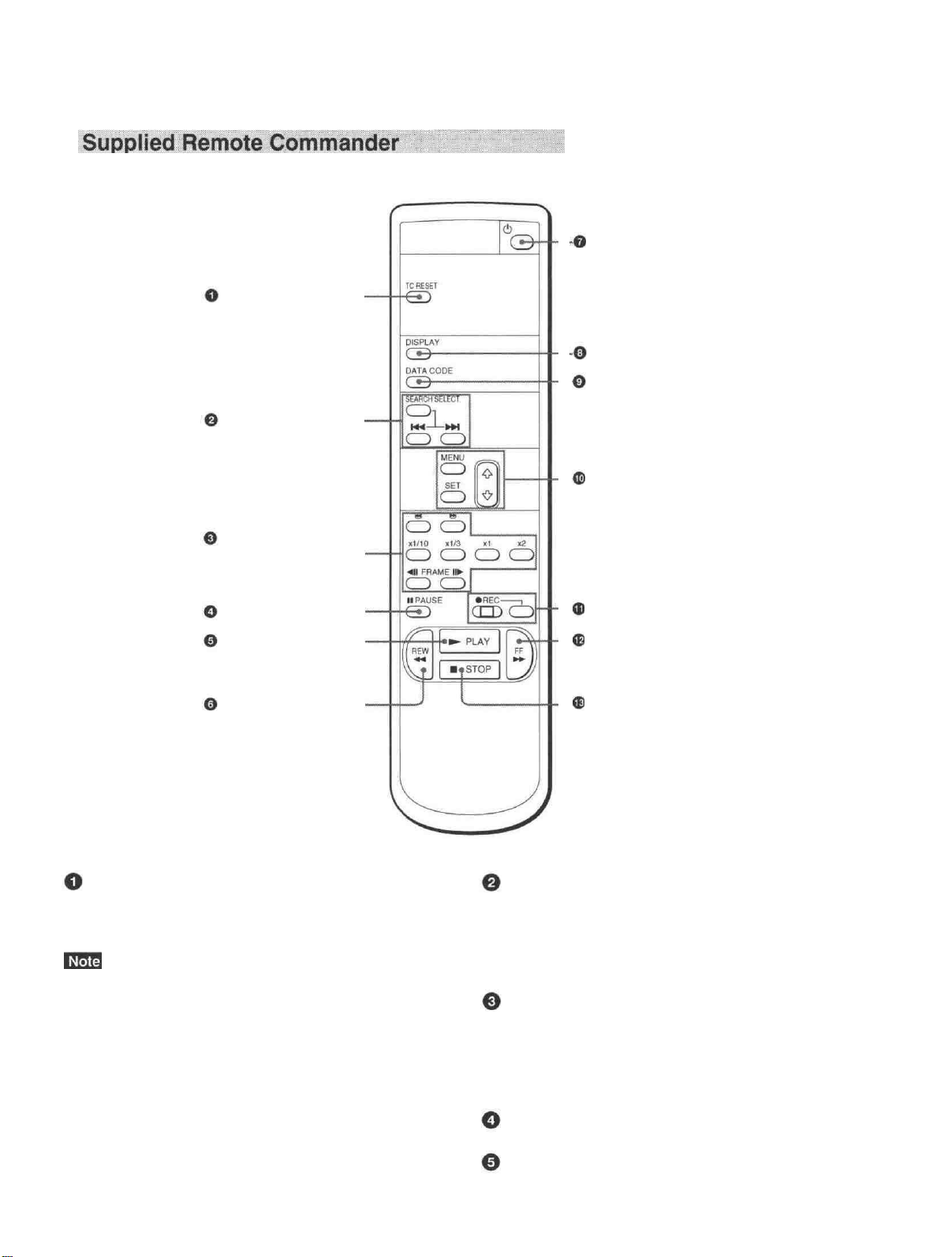
TC RESET button
SEARCH SELECT
buttons
Buttons for
playing at various
speeds
On/standby switch
DISPLAY button
DATA CODE button
Buttons for menu operation
PAUSE button
PLAY button -
REW button -
REC buttons
FF button
STOP button
TC RESET button SEARCH SELECT buttons
Press this button to reset the time code to 00:00:00:00
during recording or in the recording pause mode.
Press these buttons to search for scenes using the
search function.
For details on the search function, see "Searching using the
search function" on page 29
When the command mode of a Sony device / remote
commander is set to VTR 4;
• if you press this button while pointing the Remote
Commander toward a Sony device other than this
unit, the HMS counter on that machine will be reset
Buttons for playing at various speeds
You can play back a tape at normal speed or at a speed
other than normal with these buttons.
For details, see "Playing at various speeds" on page 28
to zero.
• if you press a counter reset button on a Sony remote
commander while pointing it toward this unit during
PAUSE button
recording or in the recording pause mode, the time
code will be reset to zero.
PLAY button
Chapter 1 Overview
13
Page 14
Location and Function of Parts
REW button
On/standby switch
DISPLAY button
Press this button to see indications, such as time code
and tape remaining time, on the monitor screen.
For details on displayed data, see "Displaying various
data" on page 26
DATA CODE button
Press this button to see the data codes (recording date/
time, camera data) on the monitor screen.
For details on data codes, see "Displaying data recorded
on a tape " on paee 25
Buttons for menu operation
Press these buttons to operate the menu.
REC buttons
When you press these buttons at the same time, the
REC and PLAY indicators light and recording begins.
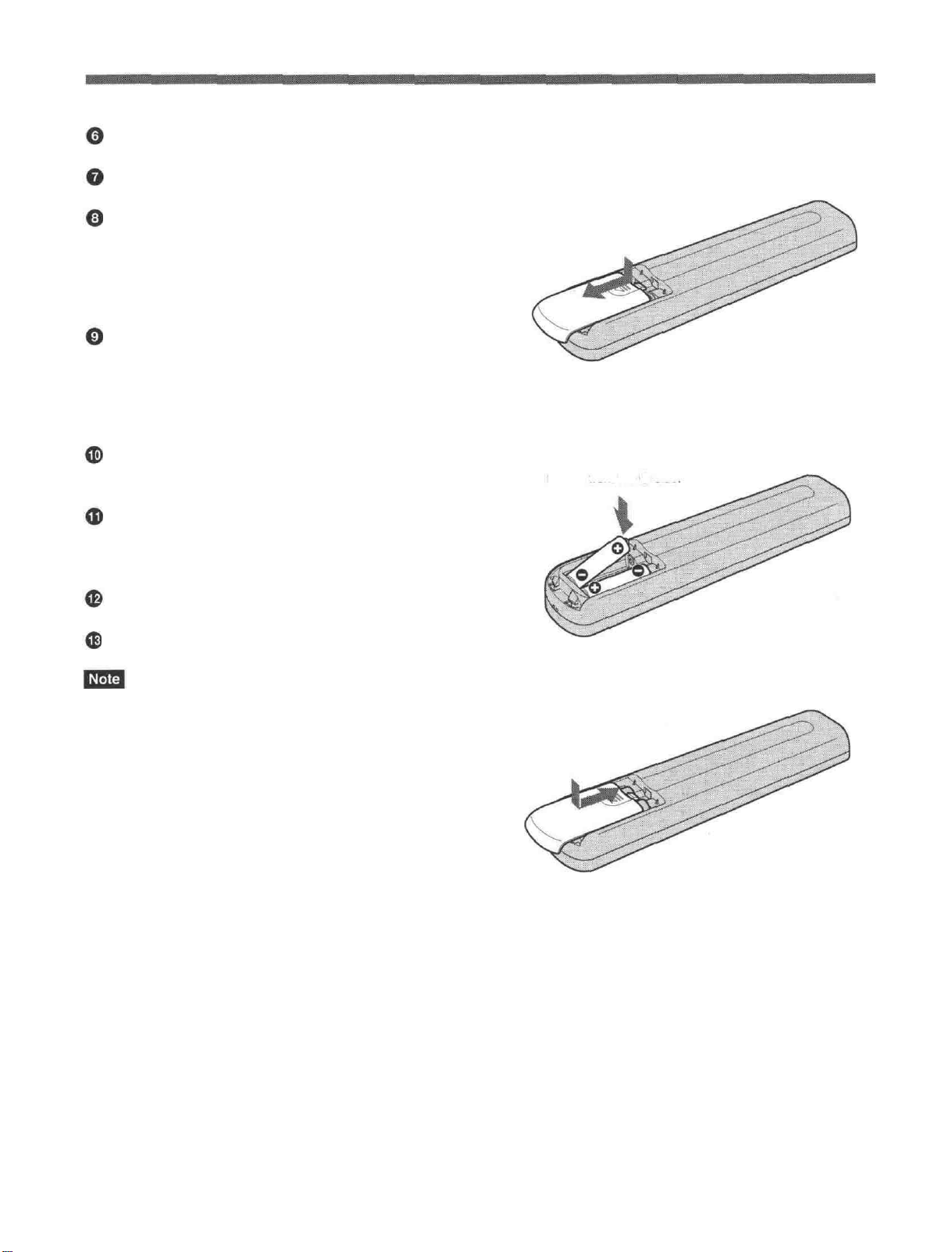
Battery installation
1
Push and slide the lid to open.
Install the two size AA (R6) batteries (supplied)
2
with the correct polarity.
Be sure to install the
battery from the side
FF button
® STOP button
When using the Remote Commander, set the
REMOTE CONTROL switch on the front panel to
WIRELESS. Otherwise, you cannot operate this unit
with the Remote Commander.
Replace the lid.
3
Notes on batteries
• Make sure that the battery orientation is correct when
inserting batteries.
• Do not mix an old battery with a new one, or mix
different types of batteries.
• If you will not use the Remote Commander for a long
time, remove the batteries to avoid damage from
battery leakage. If batteries have leaked, remove
them, wipe the battery compartment dry and replace
the batteries with new ones.
14
Chapter 1 Overview
Page 15
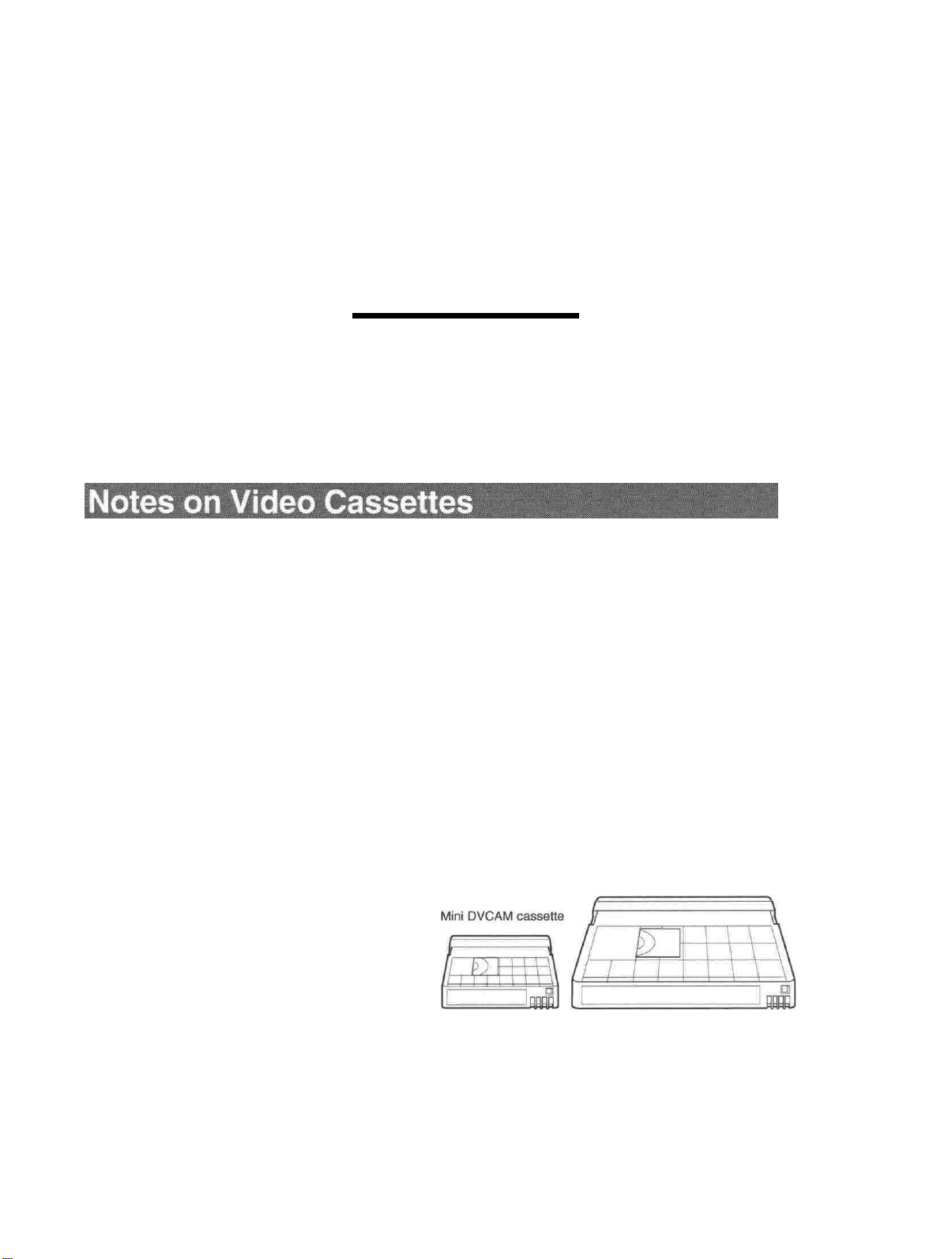
Usable cassettes
Playback and
Recording
Chapter
2
Use Standard-DVCAM cassettes or Mini-DVCAM cassettes with this unit.
The PDV-184 can record programs for 184 minutes (DVCAM format) /
270 minutes (DV format) and the PDVM-40 can record for 40 minutes
(DVCAM format) / 60 minutes (DV format).
You can get the highest quality pictures with this digital videocassette
recorder using DVCAM cassettes. You may not be able to get as good
quality with other cassettes. We recommend using DVCAM cassettes so
that you can record your one-time events in the highest quality.
DVCAM cassette
Chapter 2 Playback and Recording
15
Page 16
Notes on Video Cassettes
Cassette memory
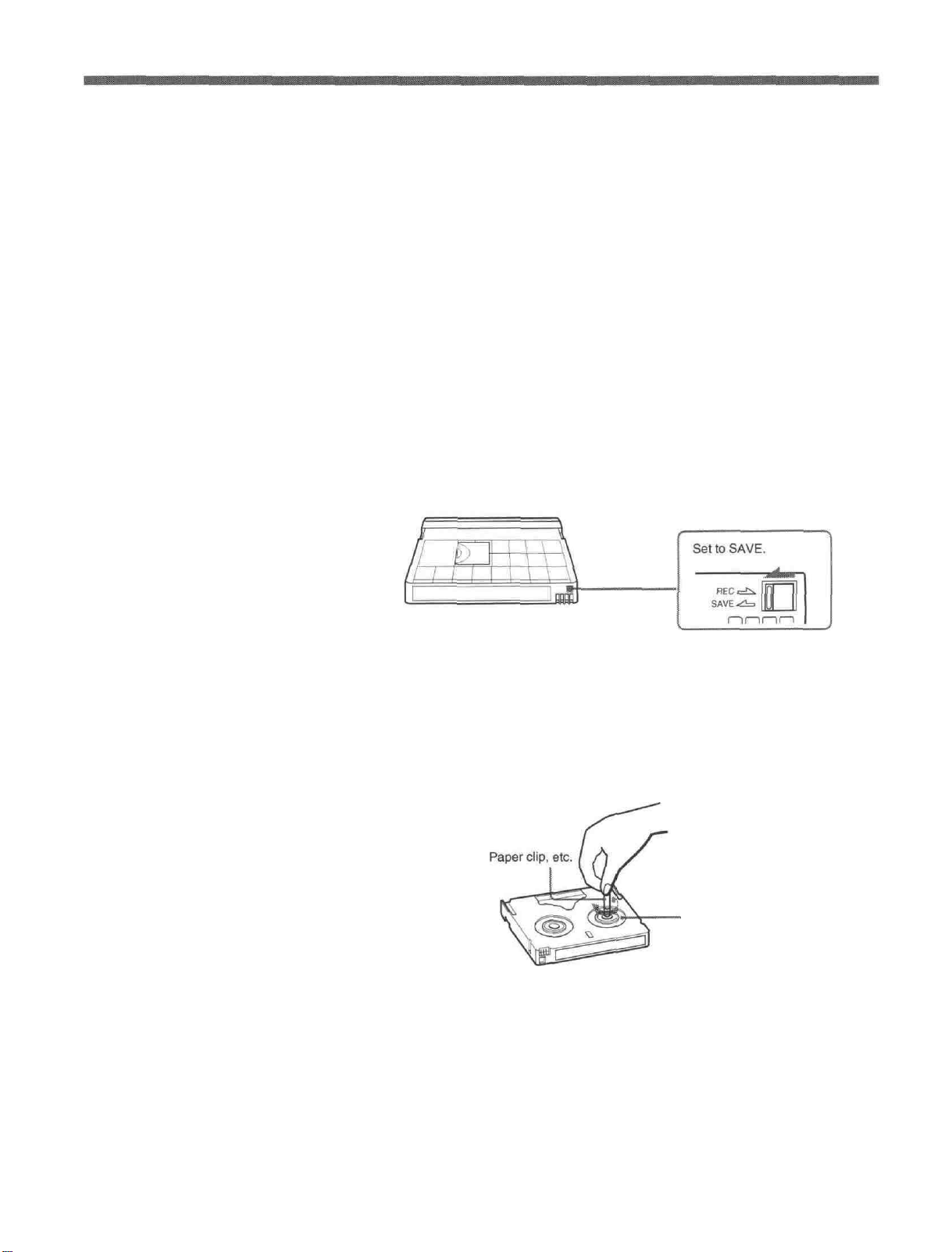
To save a recording
Cassette memory is an optional feature that is mounted on some Standard
DVCAM/DV cassettes and Mini DVCAM/Mini DV cassettes. When you
record a program, the recording date and time, and the programs' position
on the tape are stored in the cassette memory so that you can quickly
locate the program later on. CPHGK indicates that you can use the
cassettes to store up to 16 kbits of data. On this unit, you can use cassettes
on which up to 16 kbits of data can be stored.
To prevent accidental erasure of a recording, slide the REC/SAVE switch
on the cassette so that the red portion becomes visible. To record on a tape,
slide the switch so that the red portion is hidden.
REC/SAVE switch
Checking the tape for slack
Using a paper clip or a similar object, turn the reel gently in the direction
shown by the arrow. If the reel does not move, there is no slack.
Reel
16
Chapter 2 Playback and Recording
Page 17
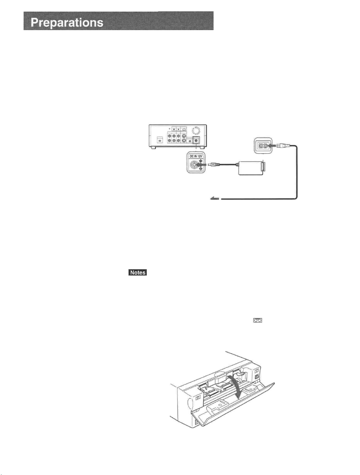
Power Preparations
Connect the power cord (supplied) to the AC adaptor (AC-SU1, supplied)
and connect the AC adaptor to the DC IN 12V connector on the unit. Then,
connect the power plug to the wall outlet.
When you undo these connections, be sure to disconnect the power cord
from the wall outlet first.
DSR-11
to
DC IN 12V
connector
AC adaptor
AC-SU1 (supplied)
Power cord (supplied)
to wall outlet
Inserting/Ejecting Cassettes
To insert a cassette
• Do not insert the cassette forcibly. The unit may be damaged.
• Do not eject/load the cassette in a place subject to light. Make sure to
close the cassette lid when using the unit. The internal sensor of the unit
may operate incorrectly if too much light finds its way into the unit.
1
With the unit powered on, confirm that the
indicator is off, then
ooen the cassette lid.
(Continued)
Chapter 2 Playback and Recording I 7
Page 18
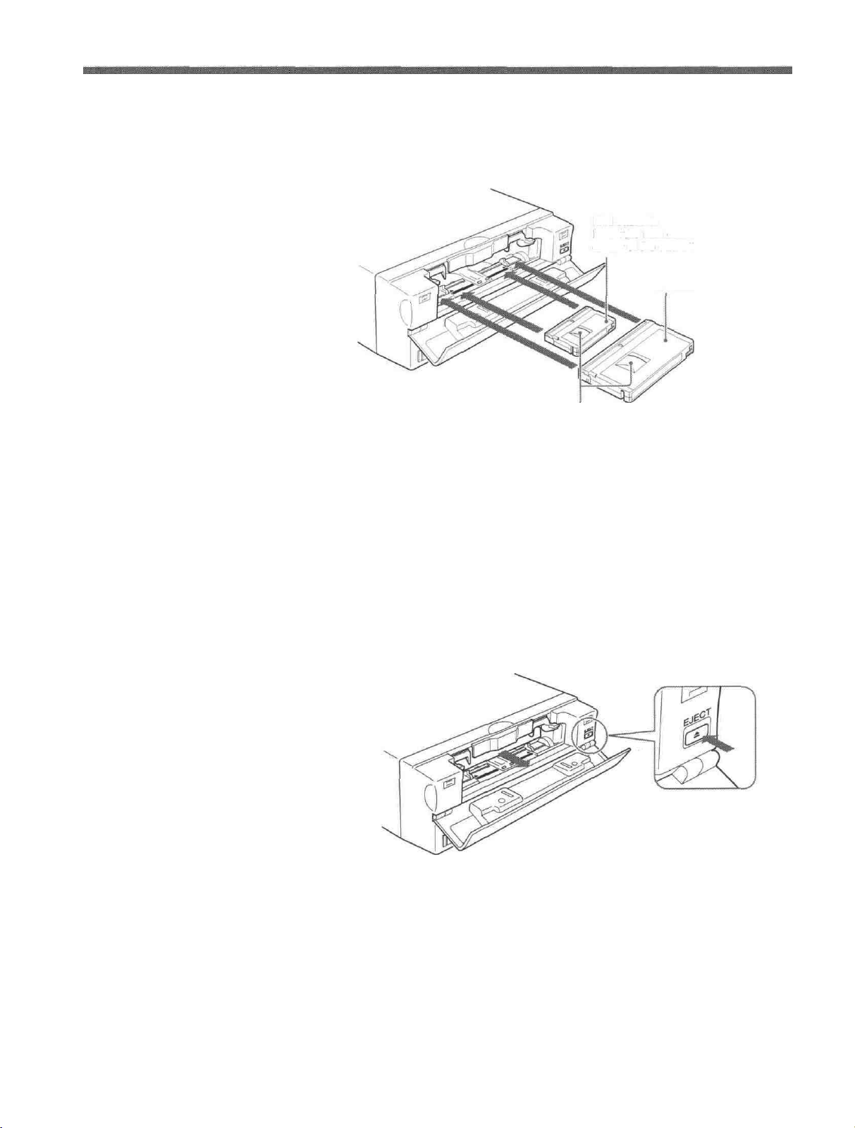
Preparations
After checking the tape for slack, hold the cassette so that the tape
2
window is facing upward, then insert it into the unit.
Mini cassette
Insert the mini cassette into the
center of the cassette compartment.
Standard cassette
Tape window facing upward
To eject the cassette
The cassette is automatically loaded into the unit.
Close the cassette lid.
3
1
With the unit powered on, open the cassette lid. Press the EJECT
button located at the right side of the cassette compartment.
18
Chapter 2 Playback and Recording
The cassette is unloaded and ejected.
Remove the cassette from the unit. Close the cassette lid.
2
Page 19

Notes on Recording/Playback
No compensation for contents of the recording
Contents of the recording cannot be compensated for if recording or
playback is not successful due to a malfunction of the unit, video tape, etc.
Copyright precautions
On recording
You cannot record any software having copyright protection signals on
this unit. If you start recording protected video and audio signals, a
warning appears on the monitor screen and the unit stops recording.
On playback
If you play back a software having copyright protection signals on this
unit, you may not be able to copy it onto other equipment.
Limitations caused by the difference in format
The unit can record and play back tapes recorded in DVCAM format. It
can also record and play back tapes recorded in DV format (SP mode).
However, due to the difference in format, you may not be able to record or
edit some tapes affected by recording conditions of the tape.
For details, see "Compatibility of DVCAM and DV Format" on page 55 .
Chapter 2 Playback and Recording 19
Page 20

Connections for Playback
To equipment with a DV jack
This section describes the necessary connections, settings, and operations
to perform playback on this unit. The same settings and operations apply
whether you are using the unit for dubbing or as a stand-alone
videocassette player.
Connecting to a computer
The video and audio signals are sent to a computer with virtually no
deterioration in quality, enabling high-quality uploading. The signal flow
is automatically detected so you do not need to make separate connections
for input and output.
Recorder Player
Computer
to
the
DV jack
Monitor
i.LINK cable (DV cable) (not supplied)
DSR-11
Signal flow
•Set DV EE OUT on the VTR SET menu to OFF.
For details on the VTR SET menu, see "VTR SET menu" on page 43 .
• With the DV connection, data codes (recording date/time, camera data)
recorded on the source tape are transmitted from this unit (player).
20
Chapter 2 Playback and Recording
Page 21

Connecting to another VCR
The video and audio signals are sent to another VCR with virtually no
deterioration in quality, enabling high-quality recording. The signal flow is
automatically detected so you do not need to make separate connections
for input and output.
Recorder Player
Other VCR
to
the
DV jack
Monitor
to
the
LANC jack
LANC cable (not supplied)
i.LINK cable (DV cable) (not supplied)
DSR-11
Signal flow
• Set DV EE OUT on the VTR SET menu to OFF.
For details on the VTR SET menu, see "VTR SET menu" on page 43 .
• With the DV connection, the sound is recorded in the same audio
recording mode as that of the source tape. To record in a different audio
recording mode from the source tape, use the analog connection instead.
• With the DV connection, data codes (recording date/time, camera data)
recorded on the source tape are transmitted from this unit (player). As a
result, when you play back a recorded tape on this unit and press the
DATA CODE button on the Remote Commander, the same data codes
recorded on the source tape are displayed on the monitor screen.
• As for the LANC connection, see "Notes for a LANC connection" on the
next page.
Chapter 2 Playback and Recording
21
Page 22

Playback
To video equipment without a DV jack
Recorder
Other VCR
Monitor
to the audio input
jacks
to the video input jack
to the S-video
input connector
to the LANC jack
Audio cable (not supplied)
Video cable (not supplied)
S-video cable (not supplied)
Player
DSR-11
LANC cable (not supplied)
Signal flow
Connect either an S-video cable or a video cable as the cable for video
signals.
• When you connect the output jacks of the recorder to the input jacks of
this unit, select the input correctly with an input select switch on the
recorder to prevent a humming noise or distortion of the picture.
•Distorted signals (e.g., when played back at a speed other than normal)
will not be recorded properly.
• The LANC connection transmits signals such as control signals, time
code, time counter data, and status data.
• Jacks labeled CONTROL L have the same function as LANC jacks.
Jacks labeled REMOTE may also have the same function.
• Set the LANC switch on the recorder to M. A device which does not have
M / S switch cannot be used to control this unit.
22
Chapter 2 Playback and Recording
Page 23

Preparation on the player (this unit)
Various text data are superimposed and output from the VIDEO jack or
the S VIDEO connector on the OUTPUT jacks. If you want to record
video signals without text data, carry out the following operations.
• Set TITLE DISP and LABEL DISP on the CM SET menu to OFF.
• Depending on the displayed items, press the MENU, DATA CODE,
DISPLAY or SEARCH SELECT button on the Remote Commander to
clear the text data on the monitor screen.
For details on text data, see "Displaying data recorded on a tape " on page 25
For details on the CM SET menu, see "CM SET menu" on page 46 .
1
Power on the video monitor, then set the monitor's input switch
according to the signals input from the recorder.
2
Set up the recorder.
For details, refer to the instruction manual of the recorder.
Power on this unit by pressing the ON/STANDBY switch on this unit.
3
and "Displaying various data " on page 26 .
When you play back a tape recorded in 4-channel mode (Fs32k),
4
adjust the balance between channel 1/2 and channel 3/4 with AUDIO
MIX on the AUDIO SET menu.
For details
The AUDIO MIX on the AUDIO SET menu (audio balance
adjustment) does not function on the source audio output through the
DV IN/OUT connector.
on
the
AUDIO
SET
menu, see
"AUDIO
SET
menu"
on page 44
Chapter 2 Playback and Recording
23
Page 24

Playback
This section describes the procedures used to play back a tape and send
signals to another VCR. For details on the procedures required when using
a computer as a recorder, refer to the instruction manual of your computer
or the user's manuals of the software installed in it.
1
After checking the tape for slack and confirming that the indicator
is off, hold the cassette so that the tape window is facing upward, then
insert it into this unit.
For details on checking the tape for slack, see "Notes on Video Cassettes" on
page 15 .
Do not insert the cassette forcibly. The unit may be damaged.
The cassette is automatically loaded into the unit.
Press the PLAY button.
2
This unit starts playback.
To stop playback
Press the STOP button on the unit.
To pause playback
Press the PAUSE button on the unit.
• When this unit is playing back a part of the tape where the recording
format has been changed between the DVCAM format and the DV
format, the picture and sound may be distorted.
• This unit cannot play back a tape recorded in the LP mode of the
consumer DV format.
24
Chapter 2 Playback and Recording
Page 25

Displaying data recorded on a tape
If you record on a tape using a Sony digital camcorder (DSR-200/200P,
200A/200AP, PD100/PD100P, PD100A/PD100AP, PD150/PD150P, 250/
250P, etc.), data codes (the shutter speed, SteadyShot, program AE mode,
white balance, iris, gain, date and time) can be recorded on the tape. You
can check these data items during playback on this unit.
Press the DATA CODE button on the Remote Commander during
playback.
Each time you press the DATA CODE button, the display changes as
follows.
No indicator
Recording
date/time
Date
Time
Shutter speed
SteadyShot
Program AE
White balance
Gain
Iris
Chapter 2 Playback and Recording
(Continued)
25
Page 26

Playback
Displaying various data
• The data codes are also displayed by setting DATA CODE on the
DISPLAY SET menu. You can change the displayed item in the same
way as described above.
Example
Menu setting : CAMERA
Display : camera
For details on the DISPLAY SET menu, see "DISPLAY SET menu " on page 45
data—>
no indicator
—>
recording date/time
—>
camera data
• Camera data items show the settings of a tape recorded by a digital
camcorder (DSR-200/200P, 200A/200AP, PD100/PD100P, PD100A/
PD100AP, PD150/PD150P, 250/250P, etc.). This unit cannot record
camera data.
• When the data codes were not recorded, "- - -" appears instead.
• Some of the camera data items displayed on the monitor screen by this
unit are different from those shown by the digital camcorder.
You can check various data items such as the time code, tape remaining
time, etc. on the monitor screen. These data items are useful for normal
recording/playback operation.
An item with * is displayed when you press the DISPLAY button on the Remote
Commander.
You can hide the item by pressing the DISPLAY button again.
26
Cassette memory indicator*
This is shown when a cassette with cassette memory has been loaded.
Tape transport mode indicator*
Displays the tape transport mode.
Chapter 2 Playback and Recording
Page 27

Time code indicator*
•Displays the time code. In the drop frame mode (only for NTSC), a
period is displayed between the minute and second. (Example:
00:12.58:00)
•Displays the diagnostics code numbers if the self-diagnostic function is
enabled.
Tape remaining time indicator*
If REMAIN on the DISPLAY SET menu has been set to ON, the
remaining tape time is displayed.
If the tape has been rewound to the beginning, this indicator will not show
the tape time remaining when the tape is inserted into the unit. The
remaining tape time is displayed after the tape runs for a while.
Search indicator
Displays the search mode when you search for scenes with the Remote
Commander or the DSRM-20 (not supplied).
For details on the search function, see "Searching using the search function" on
page 29 .
Index indicator*
Displays the INDEX MARK when an index has been marked.
Caution indicators*
Displays a caution.
For details on cautions, see "Alarm Messages" on page 51 .
DVCAM/DV indicator*
In the EE and recording modes, displays the recording format selected in
REC MODE on the VTR SET menu. During playback, displays the
recording format recorded on the tape.
Audio mode indicator*
In the EE and recording modes, displays the audio mode selected in
AUDIO MODE on the AUDIO SET menu. During playback, displays the
audio mode recorded on the tape. When inputting signals from the DV IN/
OUT connector, displays the audio mode of signals input from the DV IN/
OUT connector.
Input signal indicator*
Displays the INPUT SELECT selector setting.
NS (Non Standard) audio mode indicator*
This is shown when you play back a tape in the unlock audio mode or
when the unlock mode signal has been input from the DV IN/OUT
connector. Always this is shown when the REC MODE on the VTR SET
menu has been set to DV SP and the unit is in the EE mode.
For details on the unlock mode, see "Compatibility of DVCAM and DV Format"
on page 55 .
Chapter 2 Playback and Recording
27
Page 28

Playback
Playing at various speeds
You can enjoy playback functions using the Remote Commander.
To change playback direction
Press the FRAME buttons during playback at various speeds.
To play back in the forward direction, press the button; in the
backward direction, press the button.
To hear the sound when playing at various speeds
If you want to hear the sound when playing at various speeds, set JOG
AUDIO on the AUDIO SET menu to ON.
For details on the AUDIO SET menu, see "AUDIO SET menu " on page 44 .
When the command mode of a Sony device / remote commander is set to
VTR4;
• if you press the x l/3 button while pointing the Remote Commander
toward a Sony device other than this unit, the playback speed may turn to
1/5 of normal speed.
• if you press the x l/5 button on a remote commander while pointing it
toward this unit, the playback speed will turn to 1/3 of normal speed.
28
Chapter 2 Playback and Recording
Page 29

Searching using the search function
There are four kinds of search available on this unit:
- Searching for the beginnings of recordings: Index search
- Searching for the boundaries of recorded tape by title: Title search*
- Searching for a point on the tape where the recorded date changes: Date
search
- Searching for scenes recorded in the photo mode with a digital
camcorder: Photo search
-*A function available only on a cassette with cassette memory
Searching with the cassette memory
If you set the CM SEARCH on the CM SET menu to ON and the tape has
cassette memory, the recordings are listed in the chronological order in
which they were made. You can search using this chronological list.
If the tape does not have cassette memory, you cannot search for scenes in
chronological order.
For details on the CM SET menu, see "CM SET menu" on page 46 .
1
Press the SEARCH SELECT button on the Remote Commander to
select the search type: INDEX, TITLE, DATE or PHOTO SEARCH.
A chronological list appears on the monitor screen.
When selecting INDEX SEARCH
The date and time display can be changed by setting DATE DISP and TIME
DISP on the DISPLAY SET menu.
For PAL model, "PROG" is displayed instead of'CH."
For details on the DISPLA Y SET menu, see "DISPLA Y SET menu" on page
45
.
Press the button to select a recording.
2
The unit starts searching and when it locates the recording, begins
playback. During Photo search, the unit turns to the playback pause
mode.
Chapter 2 Playback and Recording
29
Page 30

Playback
Searching without cassette memory
When you use a tape without cassette memory, the unit searches in the
order of the actual positions of the recordings, regardless of the setting of
CM SEARCH on the CM SET menu.
When you use a tape with cassette memory, set CM SEARCH on the CM
SET menu to OFF.
For details on the CM SET menu, see "CM SET menu" on page 46
The title search is not available in searching without cassette memory.
1
Press the SEARCH SELECT button on the Remote Commander to
select the search type.
When selecting INDEX SEARCH
2
Press the button repeatedly to locate the recording you
want.
Each time you press the
previous or next search point. When an search point is located, its
number is indicated on the monitor screen.
The unit starts searching backwards or forwards until the number
comes to zero, then plays back the recording. During Photo search, the
unit turns to the playback pause mode.
How signals are recorded
There are four different signal types, one for each search method; index,
title, date and photo signals. They are recorded by the digital camcorder
(DSR-200/200P, 200A/200AP, PD100/PD100P, PD100A/PD100AP,
PD150/PD150P, 250/250P, etc.). However, the type of signal recorded and
where it is recorded (on the tape or in the cassette memory) depends on
whether the cassette has cassette memory or which type of video
equipment is used for recording. Please note that if the signals for a certain
search type are not recorded, you cannot do that type of search. For details
on the signals used for a particular type of search, refer to the instruction
manual of the recorder.
or
button, the unit searches for the
30
Chapter 2 Playback and Recording
Page 31

When you record on this unit
Signals for
Index search*
Title search
Date search
Photo search
* The signals for Index search are recorded when you start recording in stop mode.
In cassette memory
Yes
No
No
No
On tape
Yes
No
Yes
No
• If you record another program over the beginning of the search signals,
you will not be able to locate the original program.
Search signal
If D is recorded
over the beginning of B...
B cannot be
searched for
•You cannot add search signals after recording.
To add signals only for Auto Repeat, start recording from the point you
want to add them.
• When recording on this unit, signals for index search do not have
information on the day of the week.
• Searching may not be done correctly if the signals were not recorded on a
piece of Sony-brand digital video equipment.
About the cassette memory
•A tape with mark has cassette memory. When using the 16 kbits
cassette memory, you can store up to 135 search signals. (The number
changes depending on the memory capacity of various tapes. It also
changes depending on the data size combination of index, title, date,
photo, and tape label data stored on a tape.) This unit is capable of storing
and retrieving up to 16 kbits of information in cassette memory.
• To locate recordings that did not fit in the cassette memory, or to locate
recordings in order of their position on the tape, set CM SEARCH on the
CM SET menu to OFF. You can use the same procedure to search for a
recording on a tape without cassette memory.
For details on the CM SET menu, see "CM SET menu" on page 46 .
The number of search signals that you can record is limited by the cassette
memory space available when you start recording. When you use a
previously recorded tape for repeated recordings, make more memory
space available by erasing unwanted items using ITEM ERASE or ERASE
ALL on the CM SET menu before you start recording.
Chapter 2 Playback and Recording
31
Page 32

Playback
Auto Repeat
This unit can repeat the playback of all or a part of the tape.
1 Set the AUTO REPEAT switch on the rear panel to ON.
2
Press the REW button. (If the tape is already rewound, press the PLAY
button.)
The unit rewinds the tape to its beginning, and starts playback
automatically. The unit repeats the playback from the beginning to the
first index (if there is no signal for index search on the tape, to the next
unrecorded portion; if there is no unrecorded portion, to the end of the
tape).
Auto Repeat using an external AC timer
If you connect an external AC timer (not supplied) to this unit, you can
repeat playback automatically at the preset time.
1
Connect an external AC timer (not supplied) to this unit.
DSR-11
AC adaptor
AC timer
to a wall outlet
Set the AUTO REPEAT switch on the rear panel to ON.
2
Set the starting time on the external AC timer.
3
At the preset time, the power of this unit turns on, and after a few
seconds (no more than 30), Auto Repeat playback starts automatically.
The unit repeats the playback from the beginning to the first index (if
there is no signal for index search on the tape, to the next unrecorded
portion; if there is no unrecorded portion, to the end of the tape).
32
Chapter 2 Playback and Recording
Page 33

• The unit cannot search for a signal for index search or an unrecorded
portion within 20 seconds of the beginning of the playback.
• While a tape is running, be sure not to turn off the power by using an AC
timer. The unit and the tape may be damaged. When turning off the
power of the unit, make sure to press the STOP button on this unit first to
stop the tape transport, then turn off the power.
To stop Auto Repeat
Press the STOP button on this unit.
To release the Auto Repeat mode
Set the AUTO REPEAT switch on the rear panel to OFF.
Chapter 2 Playback and Recording
33
Page 34

Connections for Recording
To equipment with a DV jack
This section describes the necessary connections, settings and operations
to perform recording on this unit. The same settings and operations apply
whether you are using the unit for dubbing or as a stand-alone recorder.
Connecting to a computer
The video and audio signals are sent from a computer with virtually no
deterioration in quality, enabling high-quality downloading. The signal
flow is automatically detected so you do not need to make separate
connections for input and output.
Player Recorder
Monitor
Computer
DSR-11
to the
DV jack
i.LINK cable (DV cable) (not supplied)
Signal flow
• With the DV connection, data codes (recording date/time, camera data)
are transmitted from the computer (player). However, the contents of the
cassette memory are not transmitted.
• If no picture appears via the DV jack, disconnect, then reconnect the
i.LINK cable (DV cable).
34
Chapter 2 Playback and Recording
Page 35

Connecting to another VCR
The video and audio signals are sent from another VCR with virtually no
deterioration in quality, enabling high-quality recording. The signal flow is
automatically detected so you do not need to make separate connections for
input and output.
Player Recorder
Other VCR
to
the
DV jack
Monitor
to the
LANC jack
LANC cable (not supplied)
i.LINK cable (DV cable) (not supplied)
DSR-11
Signal flow
• With the DV connection, the sound is recorded in the same audio
recording mode as that of the source tape. To record in a different audio
recording mode from the source tape, use the analog connection instead.
•With the DV connection, data codes (recording date/time, camera data)
recorded on the source tape are transmitted from the other VCR (player).
As a result, when you play back a recorded tape on this unit and press the
DATA CODE button on the Remote Commander, the same data codes
recorded on the source tape are displayed on the monitor screen.
However, the contents of the cassette memory are not transmitted.
• If no picture appears via the DV jack, disconnect, then reconnect the
i.LINK cable (DV cable).
• As for the LANC connection, see "Notes for the LANC connection" on
the next page.
Chapter 2 Playback and Recording
35
Page 36

Recording
To video equipment without a DV jack
Player
Other VCR
Monitor
to the audio
output jacks
to the video output
jack
to the S-video
output connector
to the LANC jack
Audio cable (not supplied)
Video cable (not supplied)
S-video cable (not supplied)
Recorder
DSR-11
LANC cable (not supplied)
Signal flow
Connect either an S-video cable or a video cable as the cable for video
signals.
• When recording analog input signals, this unit can digitally output the
signals from the DV IN/OUT connector for backup. Set DV EE OUT on
the VTR SET menu to ON.
For details on the VTR SET menu, see "VTR SET menu" on page 43).
• When you connect the output jacks of this unit to the input jacks of the
player, select the input correctly with the INPUT SELECT selector on this
unit to prevent a humming noise or distortion of the picture.
• Distorted signals (e.g., when played back at a speed other than normal)
will not be recorded properly.
• The LANC connection transmits signals such as control signals, time
code, time counter data, and status data.
' Jacks labeled CONTROL L have the same function as LANC jacks. Jacks
labeled REMOTE may also have the same function.
36
Chapter 2 Playback and Recording
Page 37

Preparation on the recorder (this unit)
• Before recording, set the date and time on the unit so that the recording
time can be written into the search signal. You can set the date and time
by setting CLOCK SET on the OTHERS menu.
For details on the OTHERS menu, see "OTHERS menu" on page 49.
•Editing is not possible with a tape that is copyright protected.
1
Power on the video monitor, then set the monitor's input switch
according to the signals input from this unit.
2
Set up the player to play back a tape.
For details, refer to the instruction manual of the player.
When the player is connected to the INPUT jacks on this unit, set the
NTSC/PAL select switch on this unit to the appropriate position
according to the input signals.
For NTSC formatted signals, set the switch to NTSC and for PAL
formatted signals, set it to PAL.
For details on the NTSC/PAL select switch setting, see "Rear Panel" on page
12
.
• Do not change the NTSC/PAL select switch setting during recording.
• If the color system of the input signals is different from that of the
switch setting, both picture and sound will be muted.
• You do not need to set the NTSC/PAL select switch when inputting
the signals to the DV IN/OUT connector. The unit detects the color
system of the input signal automatically. However when the NTSC/
PAL select switch is set to PAL, the time code generated by the unit
while recording in DVCAM format turns to the non-drop frame mode.
Even if an NTSC formatted signal is input from the DV IN/OUT
connector, the time code generated by the unit is non-drop frame
mode regardless of the TC FORMAT setting on the OTHERS menu.
If you intend to set the unit to generate the time code in the drop
frame mode, set the switch to NTSC.
Power on this unit by pressing the ON/STANDBY switch on this unit.
4
(Continued)
Chapter 2 Playback and Recording
37
Page 38

Recording
Select an input signal by switching the INPUT SELECT selector on
5
this unit.
DV: to record input signals from the DV IN/OUT connector
S VIDEO: to record input signals from the S VIDEO connector on the
INPUT jacks
VIDEO: to record input signals from the VIDEO jack on the INPUT
jacks
Do not change the selector setting during recording. Otherwise, noise
is output to the picture and sound and that portion will not be recorded
properly.
When the player is connected to the INPUT jacks on this unit, select
6
the audio mode.
Select the desired mode by setting AUDIO MODE on the AUDIO SET
menu.
Audio mode
4-channel mode
2-channel mode
For details on the AUDIO SET menu, see "AUDIO SET menu" on page 44
Set the menu to
FS32K
FS48K
• In the DVCAM format, there are two audio modes, with either two
channels at 48 kHz or four channels at 32 kHz. It is not possible to
select other modes (for example with two channels at 32 kHz).
• When recording in 4-channel mode on this unit, audio signals are
recorded only in channels 1/2. When you are going to dub sounds
onto the tape, set AUDIO MODE to FS32K. (To dub a sound onto a
tape (audio dubbing), you need another VCR that has audio dubbing
capabilities. This unit does not have this function.)
• During recording, you cannot change the audio mode selection.
38
Chapter 2 Playback and Recording
Page 39

Recording Procedure
This section describes the procedures used to record signals sent from
another VCR to this unit. For details on the procedures required when
using a computer as a player, refer to the instruction manual of your
computer or the user's manuals of the software installed in it.
1
After checking that the REC/SAVE switch is set to REC, checking the
tape for slack and confirming that the [20] indicator is off, hold the
cassette so that the tape window is facing upward, then insert it into
this unit.
For details on the REC/SAVE switch and checking the tape for slack, see
"Notes on Video Cassettes" on page 75 .
The cassette is automatically loaded into the unit and the tape will stop.
2
Press the playback button on the player.
The player starts playback.
Press the PLAY button while holding down the REC button.
3
The unit starts recording and the index is marked.
To stop recording
Press the STOP button on the unit.
To pause recording
Press the PAUSE button on the unit.
To display useful data for recording on the monitor screen
Press the DISPLAY button on the Remote Commander.
For details on displayed data, see "Displaying various data " on page 26 ..
Chapter 2 Playback and Recording
39
Page 40

To install the unit
Put the unit into the supplied rack as illustrated below. You can install it
either standing on its left side or on its right side.
Align the V on the unit
with the A on the rack.
• Be sure to use the supplied rack. Without the rack, the unit may topple
over and may be damaged or may cause injury.
• Install the unit on a flat place.
• When inserting a cassette, especially a mini cassette, hold it until it is
loaded into the unit. Otherwise the cassette may fall out and the tape may
be damaged.
For details on inserting a cassette, see "Notes on Video Cassettes" on page 15
.
40
Chapter 2 Playback and Recording
Page 41

Chapter
Adjusting and Setting
Through Menus
The unit allows you to set various parameters in the
menus. Before you start using the unit, set the internal
clock in CLOCK SET on the OTHERS menu. Except
for clock setting, you can use all other factory-set
default parameters but change them as needed.
If the internal backup battery is exhausted, the menu
settings will be initialized. The internal backup battery
is fully charged if you connect the power to the unit
for about 10 hours. The menu settings will be kept for
about one month.
Displaying the menu
Press the MENU button on the Remote Commander.
The menu is superimposed on the analog video output.
Changing the menu settings
Pressing the buttons on the Remote
1
Commander, select the menu icon you want to
change, then press the SET button on the Remote
Commander.
Pressing the
2
want to change, then press the SET button.
Pressing the buttons, change the setting.
3
Press the SET button to return to the submenu.
4
Repeat steps 2 to 4, as needed.
5
To return to step 1
Pressing the
press the SET button.
To exit from the menu
Press the MENU button again.
buttons, select the submenu you
buttons, select
RETURN, then
Icons
Submenus
Chapter 3 Adjusting and Setting Through Menus
41
Page 42

Operating the Menus
The menu of this unit consists of the following menus
and submenus.
Menu
VTR SET ————— REC MODE (page 43)
AUDIO SET———— AUDIO MODE (page 44 )
DISPLAY SET-T
CM SET ————r
OTHERS ————— DV IN TC (page 49 )
Submenu (page)
— FF/REW SPD (page 43)
— STILL TIME (page 43 )
— FROM STILL (page 44 )
— FROM REC P (page 44 )
— DV EE OUT (page 44 )
1— STILL PICT (page 44 )
— JOG AUDIO (page 45 )
\
— AUDIO MIX (page 45)
i— [^REMAIN (page 45 )
— DATA CODE (page 45 )
— COLOR BAR (page 45 a)
— DATE DISP (page 45 )
'— TIME DISP (page 45 )
j— CM SEARCH (page 46 )
— TITLE DISP (page 46 )
— LABEL DISP (page 46 )
— TAPE LABEL (page 46 )
— ITEM ERASE (page 47 )
\
— ERASE ALL (page 48 )
— TC FORMAT (page 49 )
— CLOCK SET (page 49)
I— HRS METER (page 49 )
a) COLOUR BAR for PAL model
b) available only when you use an NTSC formatted signal
42
Chapter 3 Adjusting and Setting Through Menus
Page 43

Menu Contents
VTR SET menu
Initial settings are indicated with rectangles.
Icon/Menu
VTR SET
Submenu
(page)
REC MODE
FF/REW SPD
STILL TIME Selects the time to switch to the tape protection mode from the still mode.
Setting
Switches the recording mode between DVCAM and DV (SP mode only). When you play
back a tape, the DVCAM/DV setting will be automatically switched; you do not need to use
this item.
Records in DVCAM format.
DV SP: Records in DV format (SP mode).
• This unit is not compatible with playing or recording in LP mode of the consumer DV format.
• You cannot change the setting while recording.
• It is recommended that you record in the DVCAM format. There are some limitations with
respect to DV recording depending on machine specifications and the consumer DV
format as follows:
- The head system is optimized for DVCAM recording. A DV recording overwrites the last
track just before the beginning of the recording. As a result, at the border of these two
recorded portions, picture and sound may be distorted.
- The sound will be recorded unsynchronized. (unlock mode)
- The time code is fixed to the drop frame mode. (only for NTSC)
- The DV IN TC setting on the OTHERS menu turns invalid. The unit records internal time
code.
• If you dub a consumer DV tape from the DV IN/OUT connector on this unit, keep the
following in mind:
- Set the REC MODE to DV SP. If the REC MODE has been set to DVCAM, a tape with
an invalid format (recording speed: DVCAM, sound: unsynchronized, unlock mode) will
be made. (The unit cannot convert unlock mode sound to lock mode sound.)
- If you edit a tape with an invalid format in the DSR-70/70P, DSR-80/80P, DSR-85/85P,
DSR-2000/2000P, etc., there may be some restrictions.
For details on DVCAM/DV format compatibility, see "Compatibility of DVCAM and DV
Format" on page 55.
Selects the taoe transport mode in fast-forward and rewind.
Fast-forwards or rewinds the tape at maximum speed without displaying the
picture.
SHUTTLEMAX: Fast-forwards or rewinds the tape at maximum speed (about 14 times
normal speed for NTSC; about 17 times normal speed for PAL) while displaying the
picture.
30 SEC: 30 seconds
: 1 minute
2 MIN: 2 minutes
3 MIN: 3 minutes
5 MIN: 5 minutes
• If the unit is left in playback pause mode for a long time, the tape or the video heads may
be damaged or the video heads may become clogged. Select the shortest time possible
—particularly when using a Mini-DV cassette that is longer than 60 minutes, select 30
SEC or1
• When the setting is changed, the first tape protection mode change uses the time setting
from before the settings were changed. From the second tape protection mode change,
the new time setting is used.
MIN.
(Continued)
Chapter 3 Adjusting and Setting Through Menus
43
Page 44

Operating the Menus
Icon/Menu
VTR SET FROM STILL Selects the tape protection mode which to change the mode from the still mode.
Submenu
(page)
FROM REC
P
DV EE OUT
(page 36 )
STILL PICT
Setting
Forwards one frame.
STOP: Stops the tape.
Selects the tape protection mode that the system changes to after the recording has been
paused for more than five minutes.
: Stops the tape.
REC PAUSE: Maintains the recording pause mode.
When the recording pause mode continues for a long time after you select REC PAUSE, the
tape may be damaged or the video heads may be damaged or clogged. If there is no other
reason to do this, select STOP. Particularly when you use a Mini-DV cassette that is longer
than 60 minutes, select STOP.
Selects the output from the DV IN/OUT connector in the EE mode.
|OFF|: Does not output DV signals converted from analog input signals.
ON: Outputs DV signals from the DV IN/OUT connector that were converted from selected
analog input signals.
• During playback, the unit outputs DV signals from the DV IN/OUT connector regardless of
this setting.
• When you connect a computer to the DV IN/OUT connector, depending on your computer
software, the selected analog input signals may be output to the computer even if this item
is set to OFF.
Selects the image displayed in the still mode.
: Displays an optimized image according to the movement in the image.
FRAME: Displays a frame image.
FIELD: Displays a field image.
AUDIO SET menu
Icon/Menu
AUDIO SET
Submenu
(page)
AUDIO
MODE
(page 38 )
If you select FIELD, the image of field 2 is displayed.
Setting
Selects the audio mode.
Switches the audio mode to the four channel mode (12-bit mode).
FS48K: Switches the audio mode to the two channel stereo mode (16-bit mode). (This
setting records the sound in all audio ranges, providing a high-quality sound recording.)
• This item is disabled when inputting signals from the DV IN/OUT connector.
• You cannot display the selection screen while in the recording mode.
• Noise may occur at the moment you switch the audio mode.
• When you are going to dub sounds onto the tape, set this item to FS32K. (To dub a sound
onto a tape, you need another VCR which has audio dubbing capabilities. This unit does
not have this function.)
44
Chapter 3 Adjusting and Setting Through Menus
Page 45

DISPLAY SET menu
Chapter 3 Adjusting and Setting Through Menus
45
Page 46

Operating the Menus
CM SET menu
46
Chapter 3 Adjusting and Setting Through Menus
Page 47

(Continued)
Chapter 3 Adjusting and Setting Through Menus
47
Page 48

Operating the Menus
48
Chapter 3 Adjusting and Setting Through Menus
Page 49

OTHERS menu
Chapter 3 Adjusting and Setting Through Menus
49
Page 50

Maintenance
Please check the following before contacting your Sony dealer.
Chapter
4
Symptom
The power cannot be turned on.
The unit will not operate even if the power
has been turned on.
The cassette cannot be inserted.
It takes time to eject the cassette.
No picture.
Noise appears on the screen.
No picture via the DV jack.
The audio is noisy.
Pause is released automatically.
The picture and sound are muted in the
EE or recording mode.
The Remote Commander or remote
control unit does not work.
Though DV IN TC on the OTHERS menu
was set to EXTERNAL, the time code of
the signals input from the DV IN/OUT
connector cannot be recorded.
When the unit is recording an NTSC
formatted signal input from the DV IN/OUT
connector in DVCAM format, even if the
TC FORMAT on the OTHERS menu is set
to DF, the time code is recorded in nondrop frame mode.
Cause/Remedy
The AC adaptor is disconnected. ---- Connect the AC adaptor.
• Moisture condensation has occurred. --- Turn off the power and disconnect the
AC adaptor. Connect the AC adaptor after about one minute and turn on the
power. Then, if there is a cassette in the unit, remove the cassette and keep the
cassette lid open, power on the unit and leave it on for more than one hour.
• The cassette is not inserted straight. --- Insert it straight.
• There is moisture condensation on the head drum. --- Keep the cassette lid
open and turn the power on. Then, wait more than one hour.
• The cassette is not inserted straight. --- Insert it straight.
•
Another cassette has
the one you want to load.
This is not a malfunction.--- This unit ejects the cassette slowly to protect the tape.
The video heads are dirty. — Clean the video heads using the supplied cleaning cassette.
• A damaged cassette is inserted. — Insert another cassette.
• The video heads are dirty. — Clean the video heads using the supplied
cleaning cassette.
• Reconnect the i.LINK cable (DV cable) (not supplied).
• The INPUT SELECT selector is set to other than DV. -— Set it to DV.
A damaged cassette is inserted. — Insert another cassette.
Pause mode is automatically released to protect the tape.
The NTSC/PAL select switch setting is not appropriate. — Set it to a suitable
position for the color system of the input signals.
The REMOTE CONTROL switch setting is not appropriate. — Set it to a suitable
position for the device you use.
The REC MODE on the VTR SET menu is set to DV SP. Set the REC MODE
to DVCAM.
The NTSC/PAL select switch is set to PAL. —- Set it to NTSC.
been
loaded
already.---
Remove the cassette
and
insert
50
Chapter 4 Maintenance
Page 51

If an error occurs, a caution appears on the analog video outputs when you set the unit to output signals with data
items. Check them with the following list.
For details on data items, see "Displaying various data " on page 26
a)
Description/Recovery
Moisture condensation (without a cassette) —»• Keep the cassette lid
open and turn the power on, then wait more than one hour.
Moisture condensation (with a cassette) —»• Remove the cassette and
keep the cassette lid open and turn the power on, then wait more than
one hour.
You tried to record without a cassette inserted. —»• Insert a cassette.
The tape is reaching the end during recording. —»• Provide a new
cassette.
The tape reached the end and still tried to record. —»• Rewind the tape or
replace the tape with a new one.
The cassette is write-protected (The REC/SAVE switch is set to SAVE) and
you tried to record. —»• Set the REC/SAVE switch to REC or use another
cassette (See page 16 .
You did not set the clock when you turned on the unit. —>• Set the clock
with the menu (See page 49)
You tried to record a copyright-protected source.
—»• You cannot record a copyright-protected source (See page 19.
The video heads are clogged. —»• Clean the video heads with the supplied
cleaning cassette. (The unit detects if the video heads are clean only
before recording. If the video heads get clogged during recording, the unit
cannot detect it.)
The unit is running the self-diagnostics (See page 54 . This caution
display ceases when you turn on/off the power of the unit.
Monitor
NO TAPE
TAPE END
CLOCK SET
COPY
INHIBIT
0
Displayed
alternately
t
CLEANING
CASSETTE
Indicator lamp (flash)
CAUTION
Rapid flashing
Rapid flashing
Slow flashing
Slow flashing
Slow flashing
Slow flashing
Slow flashing
Rapid flashing
Rapid flashing
The indicator flashes 3.2 times per second in the rapid flashing mode and flashes 0.8 time per second in the slow flashing
a:
mode.
Chapter 4 Maintenance
51
Page 52

Notes on the video cassette recorder
Do not install the unit in a place subject to
direct sunlight or heat sources
If you do, its cabinet, mechanical parts, etc., may be
damaged.
Do not install the unit in an extremely hot
place
If the unit is left in a car parked with its windows
closed (especially in summer), its cabinet may be
damaged or it may not work correctly.
To prevent electromagnetic interference
caused by radio communication equipment
such as cellular phones, transceivers, etc.
The use of the radio communication equipment such as
cellular phones or transceivers near the unit may cause
a malfunction and can affect the audio/video signals.
The cellular phones or transceivers near the unit should
be switched off.
Do not use the unit in an area exposed to
radiation
A malfunction may occur.
If the unit is brought directly from a cold to a
warm location
Moisture may condense inside the unit and cause
damage to the video head and tape. If you use the unit
in a place subject to direct cold currents from an air
conditioner, moisture may also condense inside the
unit.
Do not place a heavy object on the unit
The cabinet may be damaged, or the unit may not work
correctly.
Do not handle the unit roughly
Avoid rough handling or mechanical shock.
To avoid damaging the cabinet finish
Plastic is often used for the surface finishing of the
unit. Do not spray a volatile solvent such as an
insecticide toward the cabinet or place rubber or vinyl
products on the cabinet for a long time. If you do, the
finish of the cabinet may be damaged or the coating
may come off.
Checking the video heads every 1000 hours
A VCR is a high-precision piece of equipment that
records and plays back the picture on a magnetic tape.
In particular, the video heads and other mechanical
parts become dirty or worn. To maintain a clean
picture, we recommend maintenance every 1000 hours,
though the conditions of use may differ depending on
temperature, humidity, dust, etc.
Cleaning of the video heads
If the video heads are contaminated, the pictures
cannot be recorded properly or the playback pictures
become noisy. If the following phenomena occur, use
the cleaning cassette (supplied) to clean the heads.
•Square-shaped noise appears on the playback picture.
• A part of the playback picture does not move.
• The playback picture does not appear on the screen.
Symptoms caused by contaminated video heads
Do not clean the cabinet with thinner or
benzine
The cabinet may be damaged or its coating may come
off. When you use a chemical-impregnated cloth, use
it according to its directions.
Clean the cabinet with soft dry cloth
When the cabinet is very dirty, clean it with a soft dry
cloth lightly moistened with a mild detergent solution
and finish it with a dry cloth.
Do not put magnetic objects close to the unit
Magnetic fields may damage the recording.
52
Chapter 4 Maintenance
Normal picture
If these images appear on the
screen, use the cleaning cassette.
To use the cleaning cassette
Refer to your cleaning cassette's operating instructions
After prolonged use, the video heads may become
worn out. If optimum picture quality is not restored
even after you have cleaned the video heads with the
cleaning cassette, the video heads may have worn out.
In that case, you have to replace the video heads with
new ones. Please consult your Sony dealer.
Page 53

Notes on the video cassettes
If the cassette memory function does not work
Reinsert the cassette a few times. The terminal portion
of the cassette may be dusty or dirty.
Cleaning the terminal
If the terminal of the cassette gets dirty, or dust sticks
to the terminal, the unit may not work correctly.
Clean the terminal with a swab once every ten times
you eject a cassette.
When bringing the unit or tape from a cold place to a
warm place or vice versa, put it in a plastic bag and
seal the bag tightly. After bringing it into the new
place, leave the bag on for more than one hour, and
remove the bag when the air temperature inside it has
reached the temperature surrounding it.
If moisture condensation occurred
You cannot operate the unit except to press the EJECT
button, and the cassette cannot be inserted. If this
occurs, turn on the power to remove the cassette, then
keep opening the cassette lid, and finally wait more
than one hour for the moisture to evaporate.
Terminal
When affixing a label on the cassette
Be sure to affix a label only on the correct location so
as not to cause malfunction of the unit.
After using a cassette
After use, please be sure to rewind the tape completely
(to prevent picture and sound distortion). Return it to
its case and store it in an upright position.
About moisture condensation
If the unit or tape is brought directly from a cold to a
warm location, moisture may condense inside or
outside the unit or tape. If you use the tape or video
heads in this condition, the tape may adhere to the
head drum, and the video heads or the tape may be
damaged, or a malfunction may occur.
Digital hours meter
The digital hours meter keeps cumulative counts of the
total operation time, the head drum rotation time, the
tape running time and the number of unthreading
operations. These counts can be displayed on the
monitor screen. Use them as guidelines for scheduling
maintenance.
In general, consult your Sony dealer about necessary
periodic maintenance checks.
The digital hours meter has the following four display
modes and you can check them in HRS METER of the
OTHERS menu (See page 49).
•OPERATION mode
The cumulative total hours of operating time is
displayed in 10-hour increments.
•DRUM ROTATION mode
The cumulative total hours of drum rotation with tape
threaded is displayed in 10-hour increments.
Moisture condensation is likely to occur under the ,
following conditions:
• The unit or tape is brought from the cold outdoors to
a warm indoor location.
• The unit or tape is brought from the air-conditioned
indoors to the hot outdoors.
•The unit is used in a place subject to cold currents
from an air conditioner.
•TAPE RUN mode
The cumulative total hours of tape running time is
displayed in 10-hour increments.
•THREADING mode
The cumulative number of tape unthreading
operations is displayed in 10-operation increments.
Chapter 4 Maintenance
53
Page 54

Notes on Use
Self-diagnostics function
The unit has a self-diagnostics display function.
This function displays the current condition of the unit
as a five-digit code (a combination of a letter and
numbers) on the analog video output. If a five-digit
code is displayed, check the following code chart. The
last two digits (indicated by DD) will differ depending
on the state of your unit.
Code
C:21:DD
C:22:DD
C:31:DD
C:32:DD
Symptom
Moisture
condensation has
occurred.
The video heads are
dirty.
To prevent the unit
from malfunctioning,
the self-diagnostics
function has taken
over.
To prevent the unit
from malfunctioning,
the self-diagnostics
function has taken
over.
Remedy
Remove the cassette
and keep the cassette
lid open and turn the
power on. After waiting
more than one hour,
insert the cassette
again.
Clean the heads using
the cleaning cassette
(supplied).
• Remove the cassette,
or turn on/off the unit.
• Disconnect the AC
adaptor. After
reconnecting it,
operate the unit.
• Turn on/off the unit.
• Disconnect the AC
adaptor. After
reconnecting it,
operate the unit.
If you are unable to resolve the problem, or a code
other than those in the above chart appears, contact
your Sony dealer or local authorized Sony service
facility and inform them of the number.
54
Chapter 4 Maintenance
Page 55

Appendix
The DVCAM format was developed as a more reliable and higher end
format than the consumer DV format. Here we explain the DVCAM and
DV formats: the differences, compatibility and limitations on editing.
Differences between DVCAM and DV format
Item
Track pitch
Audio sampling
frequency
Audio recording
1)
mode
Time code system
There are two modes for audio recording; Lock mode and Unlock mode. In
1)
Lock mode, the sampling frequencies of audio and video are synchronized. In
Unlock mode, which the consumer DV format adopts, the two sampling
frequencies are independent. The lock mode maintains high compatibility with
the higher formats and is more effective than unlock mode in digital processing
and smooth transition during audio editing.
This unit cannot record in DV format with 16 bit - 32 kHz or 44.1 kHz.
2)
The user bits cannot be set on this unit.
3)
DVCAM
15
urn
12
bit:
32
kHz
16
bit:
48
kHz
Lock mode
NTSC; SMPTE time
code (DF/NDF/including
user bits)3'
PAL; EBU time code
(including user bits)3'
DV
10
[im
12
bit:
32
kHz
16 bit: 32 kHz, 44.1 kHz, 48 kHz2'
Unlock mode
Drop frame mode (NTSC)
without user bits
Appendix
55
Page 56

Compatibility of DVCAM and DV Format
DVCAM and DV cassettes
Both DVCAM and DV cassettes can be used on DVCAM or DV video
equipment. The recording format is defined according to recorder format
as described below.
Recorder format
DVCAM
(If the REC MODE
on the
VTR
SET
menu is set to
DVCAM on this unit.)
DV
(If the REC MODE
on the
VTR
SET
menu is set to DV SP
on this unit.)
Cassette format
DVCAM
DV
DVCAM
DV
Recording format
DVCAM
DV
• This unit can record in DV format. (SP mode only)
• This digital videocassette recorder complies with the DVCAM format.
Though DV cassettes can be used for recording, we recommend that you
use DVCAM cassettes. Particularly when you use a Mini-DV cassette
that is longer than 60 minutes, do not play back the tape repeatedly (i.e.,
when editing). Set STILL TIME to 1 MIN or 30 SEC (See page 43 ),
and FROM REC P to STOP (See page 44 ).
• If you use a DV cassette to record images in the DVCAM format, the
recording time will be reduced to 2/3 of the time indicated on the DV
cassette.
• If you use a DVCAM cassette to record images in the DV format (SP
mode), the recording time will be extended to 1.5 times the time indicated
on the DVCAM cassette.
56
Appendix
Some tapes cannot be played on DVCAM or DV video equipment.
Tape
DV-formatted
DVCAM-formatted
On DV video equipment
(Consumer VCR)
Can be played back.
(A tape recorded in the
LP mode cannot be
played by some
equipment.)
Some DV video
equipment may be able
to play back a DVCAMformatted tape.
On DVCAM video equipment
(This unit)
Can be played back only when
recorded in the SP mode.
A tape recorded in the LP mode
can be played by some
equipment. (This unit can play
back a DV-tormatted tape only in
the SP mode.)
Can be played back.
Page 57

Compatibility on editing using a DV connection
When this unit is connected to other DVCAM or DV video equipment
using DV connectors, the recording format of an edited tape is defined
according to the recorder format as described below.
Source tape
DV-formatted1)
DV-formatted
DVCAM-
formatted4)
DVCAM-
formatted4)
Player format
DVCAM
DV
DVCAM
DV5)
Recorder format2)
DVCAM
DV
DVCAM
DV
DVCAM
DV
DVCAM
DV
Recorded format
DVCAM3'
DV
DVCAM3)
DV
DVCAM
DV6)
DVCAM7)
DV6)
1) On this unit, only DV-formatted tapes recorded in the SP mode can be used as
source tapes.
2) This unit will be restricted according to the REC MODE setting on the VTR
SET menu.
3) When you copy a DV-formatted tape using DVCAM video equipment, the
recorded format of the copied tape is the following DVCAM format.
• The audio recording mode of the copied tape is unlock mode.
• The time code of the copied tape is partly inaccurate.
4) If you use a DVCAM-formatted tape as described in 3) above, the audio
recording mode of the recorded tape is unlock mode and the time code is partly
inaccurate.
5) Some DV video equipment may be able to play back a DVCAM-formatted
tape. Even if the tape is played back, the contents of the playback cannot be
guaranteed.
6) The audio recording mode of the edited tape is lock mode.
7) Depending on the signal conditions of the source tape, you may not be able to
edit the tape using the DV connection.
Limitations on editing
You will find the following limitations when editing.
• Due to differences of track pitch, you cannot record or edit DV-formatted
tapes using DVCAM video equipment.
• Depending on signal conditions, you may not be able to record or edit
DVCAM-formatted tapes. In these cases, copy the tape again using
analog audio/video jacks.
Appendix
57
Page 58

System Incuts and cutouts
Recording format
DVCAM/DV (SP) format, rotating
2-head helical scan, digital
component recording
Video input
Phono jack
Input signal: 1 Vp-p
(75 ohms unbalanced)
Video signal EIA STANDARD, NTSC color Video output Phono jack
system Output signal: 1 Vp-p
CCIR STANDARD, PAL colour (75 ohms unbalanced)
Video
Quantification
Standardization
frequency
system
8-bit
NTSC:
13.5 MHz (4:1:1 Component)
PAL:
13.5 MHz (4:2:0 Component)
S video input
S video output
Mini DIN 4-pin
Luminance signal: 1 Vp-p
(75 ohms unbalanced)
Chrominance signal:
0.286 Vp-p (NTSC)
0.3
Vp-p (PAL)
(75 ohms unbalanced)
Mini DIN 4-pin
Luminance signal: 1 Vp-p
Audio (75 ohms unbalanced)
Quantification
Standardization
frequency
Usable cassettes
Recording time Standard cassette
12-bit (non-linear) or 16-bit (linear)
32 kHz (12-bit recording) or
48 kHz (16-bit recording)
Standard-DVCAM cassettes and
Mini-DVCAM cassettes
DVCAM:
184 minutes (PDV184)
180 minutes (DV270)
DV: 270 minutes (PDV184/
Audio input
Audio output
Chrominance signal:
0.286 Vp-p (NTSC)
0.3
Vp-p (PAL)
(75 ohms unbalanced)
Phono jack (L,R)
Input level: 2 Vrms (full bit)
Input impedance: more than
47 kohms
Phono jack (L, R)
Output level: 2 Vrms (full bit)
Output impedance: less than
DV270) 10 kohms
Mini cassette
DVCAM: 40 minutes (PDVM40/
DVM60)
DV- 60 minutes fPDVM40/
Control S input
LANC input/output
DV input/output
Minijack
Stereo mini-mini jack
4-pin jack
DVM60)
(We recommend that you use the
DVCAM cassettes.)
General
Power consumption
15 W (during playback)
Clock
Quartz locked
Power back-up
Back-up duration: up to one month
(after a 10-hour charge)
Peak inrush current
Hot switching inrush current,
measured in accordance with
European standard EN55103-1:
6 A (230V)
Operating temperature
5 °C to
40
°C
(41
°F
to
Storage temperature
-20
°C to +60 °C
(-A
°F to +140 °F)
104
°F)
58
Appendix
Page 59

Dimensions Approx. 180 x 73 x 265 mm
(7 !/8 x 2 Vs x 10 '/2 inches)
(w/h/d, including projecting parts
and controls)
Optional accessories
DSRM-20 Remote Control Unit
Digital video cassette
(With cassette memory)
Standard size: PDV-34ME/
64ME/94ME/124ME/184ME
Mini size: PDVM-12ME/22ME/
32ME/40ME
(Without cassette memory)
Standard size: PDV-64N/124N/
184N
Mini size: PDVM-32N/40N
Design and specifications are subject to change
without notice.
Unit: mm (inches)
Mass Approx. 2.7 kg (5 Ib 15 oz)
Supplied accessories
Remote Commander (1)
Size AA (R6) batteries (2)
AC power adaptor (1)
Power cord (1)
Rack(l)
Cleaning cassette (1)
Operating instructions
Appendix
59
Page 60

Audio recording mode
In the DVCAM format, the sound is
recorded in either 16bit (Fs48k) or 12bit
(Fs32k) mode.
Component signal
A video signal consisting of a luminance
signal (Y) and two chrominance signals
(R-Y,B-Y).
Condensation
Condensation of moisture on the tape
transport mechanisms of VCRs including
the head drum. If moisture condenses on
the head drum, the tape adheres to the
drum and causes malfunction.
Drop frame mode
In NTSC format, the actual number of
frames per second is approximately 29.97,
while that for SMPTE time code is
specified as 30. Drop frame mode is a
mode in which time code is advanced in
such a way that the difference in frame
value between real time and time code is
corrected. In this mode, two frames are
skipped at the beginning of each minute,
except for every tenth minute, so that the
frame value for time code matches that for
real time. See also "Non-drop frame
mode."
Drum
See "Head drum."
EE mode
EE is an abbreviation of "Electric to
Electric." Video and audio signals are
supplied to the VCR'S internal circuits, but
not to the recording heads.
Head drum
A metal cylinder to which video heads are
attached. During recording and playback,
the drum rotates at high speeds in
synchronization with the sync signal.
Loading
When being loaded, the tape is pulled out
of the cassette case and threaded along the
specified tape path and wrapped round the
drum to be ready for recording or
playback. Generally, this is done
automatically when you place the cassette
at the cassette entrance of the VCR. Also
called threading.
Non-drop frame mode
A mode of advancing time code in such a
way that the difference in frame value
between real time and time code is
neglected. Using this mode produces a
difference of approximately 86 seconds
per day between real time and time code,
which may cause problems when editing
programs in units of seconds using the
number of frames as a reference.
PCM audio
PCM stands for "pulse code modulation."
PCM audio means audio signals that have
been processed by pulse code modulation.
Each analog audio signal is converted into
pulses that are generated in rapid
succession, and each pulse is recorded as a
digital signal having a value of 0 or 1.
Search
To locate a particular scene by running the
tape in the fast forward or rewind mode
while viewing the picture or time codes.
Superimpose
To put a set of characters onto a picture so
that both can be seen at the same time.
Threading
See "Loading."
Time code
Signals recorded on the tape to supply
information on tape position such as the
hour, minute, second and frame, to assist
in setting edit points or searching for
particular scenes. This unit can cope with
both DF (Drop Frame) and NDF (Non
Drop Frame).
On this unit, the time code is recorded
sequently from "00:00:00:00;' from the
beginning of the tape. However, if there is
a blank section on the tape, time code is
reset and recorded from "00:00:00:00"
again from the section just after the blank
section. If the time codes are out of
sequence, you may not be able to execute
correct editing.
Unloading
When being unloaded, the tape is put into
the cassette case from the tape path of the
VCR. Generally, this is done automatically
when you press the EJECT button. Also
called unthreading.
Unthreading
See "Unloading."
12bit (Fs32k) mode
In the DVCAM format, the 12bit (Fs32k)
mode separates the audio area into 2 parts.
You can record two kinds of audio, stereo
1 and stereo 2.
16bit (Fs48k) mode
In the DVCAM format, the 16bit (Fs48k)
mode uses the whole audio area to record
one stereo track. You can get higher sound
quality.
60
Appendix
Page 61

AC timer.....
Audio mode
Auto Repeat
Camera data........
Cassette memory
Cleaning..............
Clock
..................
Date
search
..................
Drop Frame..................
DV
cassette
...................
format.....................
IN/OUT connector .
DVCAM
cassette
format.
.27
16
20
15
6
32
44
32
25
31
52
49
29
60
56
55
11
34
56
55
Menu.............................
41
Mini-DVCAM cassette.
Non Drop Frame, 60
Photo search
...............
29
Playback
at
various
speeds
.................
frame by frame....................
28
28
Remote Commander.
Searching using search function...
29
Standard DVCAM cassette...........
15
13
15
Fs32k
Fs48k
i.LINK
....................................
Index search............................
LANCjack ... 11 22 36
Lock
mode....................................
55
44
44
11
29
Tape remaining time ...
Time code ...................
Title search
Unlock mode
Usable cassette
.................
............................
..........................
27
45
49
29
55
15
Appendix
61
 Loading...