


Video Disk
Recorder
3-986-592-11 (1)
Operating Instructions
Before operating the unit, please read this manual
thoroughly and retain it for future reference.
DSR-DR1000A/DR1000AP
© 2005 Sony Corporation

Owner’s Record
The model and serial numbers are located at the bottom.
Record these numbers in the spaces provided below. Refer
to them whenever you call upon your Sony dealer
regarding this product.
Model No.
Serial No.
Important Safety Instructions
WARNING
To reduce the risk of fire or electric shock,
do not expose this apparatus to rain or
moisture.
To avoid electrical shock, do not open the
cabinet. Refer servicing to qualified
personnel only.
• Read these instructions.
• Keep these instructions.
• Heed all warnings.
• Follow all instructions.
• Do not use this apparatus near water.
• Clean only with dry cloth.
• Do not block any ventilation openings.
Install in accordance with the manufacturer’s
instructions.
• Do not install near any heat sources such as radiators,
heat registers, stoves, or other apparatus (including
amplifiers) that produce heat.
• Do not defeat the safety purpose of the polarized or
grounding-type plug. A polarized plug has two blades
with one wider than the other. A grounding-type plug
has two blades and a third grounding prong. The wide
blade or the third prong are provided for your safety. If
the provided plug dose not fit into your outlet, consult an
electrician for replacement of the obsolete outlet.
• Protect the power cord from being walked on or pinched
particularly at plugs, convenience receptacles, and the
point where they exit from the apparatus.
• Only use attachments/accessories specified by the
manufacturer.
• Use only with the cart, stand, tripod, bracket, or table
specified by the manufacturer, or sold with the
apparatus.
When a cart is used, use caution when moving the cart/
apparatus combination to avoid injury from tip-over.
THIS APPARATUS MUST BE EARTHED.
CAUTION
The apparatus shall not be exposed to dripping or
splashing and no objects filled with liquid, such as vases,
shall be placed on the apparatus.
The unit is not disconnected from the AC power source
(mains) as long as it is connected to the wall outlet, even if
the unit itself has been turned off.
Do not install the appliance in a confined space, such as a
book case or built-in cabinet.
This apparatus is provided with a main switch on the rear
panel. Install this apparatus so that user can access the
main switch easily.
• Unplug this apparatus during lightning storms or when
unused for long periods of time.
• Refer all servicing to qualified service personnel.
Servicing is required when the apparatus has been
damaged in any way, such as power-supply cord or plug
is damaged, liquid has been spilled or objects have fallen
into the apparatus, the apparatus has been exposed to
rain or moisture, does not operate normally, or has been
dropped.
2

This symbol is intended to alert the user to
the presence of uninsulated “dangerous
voltage” within the product’s enclosure
that may be of sufficient magnitude to
constitute a risk of electric shock to
persons.
This symbol is intended to alert the user to
the presence of important operating and
maintenance (servicing) instructions in
the literature accompanying the
appliance.
WARNING: THIS WARNING IS APPLICABLE FOR
USA ONLY.
Using this unit at a voltage other than 120 V may require
the use of a different line cord or attachment plug, or both.
To reduce the risk of fire or electric shock, refer servicing
to qualified service personnel.
Caution
Television programs, films, video tapes and other
materials may be copyrighted.
Unauthorized recording of such material may be contrary
to the provisions of the copyright laws.
For customers in Europe (DSR-DR1000AP only)
This product with the CE marking complies with both the
EMC Directive (89/336/EEC) and the Low Voltage
Directive (73/23/EEC) issued by the Commission of the
European Community.
Compliance with these directives implies conformity to
the following European standards:
• EN60065: Product Safety
• EN55103-1: Electromagnetic Interference (Emission)
• EN55103-2: Electromagnetic Susceptibility (Immunity)
This product is intended for use in the following
Electromagnetic Environment(s):
E1 (residential), E2 (commercial and light industrial), E3
(urban outdoors) and E4 (controlled EMC environment,
ex. TV studio).
For customers in the USA (DSR-DR1000A only)
This equipment has been tested and found to comply with
the limits for a Class A digital device, pursuant to Part 15
of the FCC Rules. These limits are designed to provide
reasonable protection against harmful interference when
the equipment is operated in a commercial environment.
This equipment generates, uses, and can radiate radio
frequency energy and, if not installed and used in
accordance with the instruction manual, may cause
harmful interference to radio communications. Operation
of this equipment in a residential area is likely to cause
harmful interference in which case the user will be
required to correct the interference at his own expense.
You are cautioned that any changes or modifications not
expressly approved in this manual could void your
authority to operate this equipment.
The shielded interface cable recommended in this manual
must be used with this equipment in order to comply with
the limits for a digital device pursuant to Subpart B of Part
15 of FCC Rules.
Voor de Klanten in Nederland
• Dit apparaat bevat een vast ingebouwde batterij die niet
vervangen hoeft te worden tijdens de levensduur van het
apparaat.
• Raadpleeg uw leverancier indien de batterij toch
vervangen moet worden.
De batterij mag alleen vervangen worden door
vakbekwaam servicepersoneel.
• Gooi de batterij niet weg maar lever deze in als klein
chemisch afval (KCA).
• Lever het apparaat aan het einde van de levensduur in
voor recycling, de batterij zal dan op correcte wijze
verwerkt worden.
3

Table of Contents
Chapter 1 Overview
Chapter 2 Preparations
Features........................................................................7
DVCAM Format ............................................................. 7
Supporting Variety of Input/Output Interfaces ...............7
Compact Size ..................................................................8
Facilities for High-Efficiency Editing............................. 8
Special Hard Disk Functions........................................... 8
Other Features ................................................................. 9
Location and Function of Parts................................10
Front Panel .................................................................... 10
Rear Panel ..................................................................... 19
Setting the Date and Time ........................................24
Setting the Time Data................................................24
Displaying Time Data and Operation Mode Indications ..
25
Using the Internal Time Code Generator...................... 26
Synchronizing Internal and External Time Codes ........ 28
Making Basic Network Settings ...............................29
To Set the IP Address.................................................... 29
To Set the Subnet Mask ................................................ 29
To Set the Default Gateway .......................................... 29
To Set Up a User Account ............................................29
Chapter 3 Recording and Playback
Recording...................................................................30
Settings for Recording ..................................................30
Recording Procedure..................................................... 32
To Set Cue Points.......................................................... 33
Long-time Recording With Video Camera................... 33
Recording Continuously by Overwriting Old Content
Recording at Set Intervals (Interval Recording) ........... 34
Starting Recording at an Alarm Input (Pre-Alarm
Playback .....................................................................34
Playback Procedure....................................................... 34
4
Table of contents
(Continuous Recording) ......................................34
Recording) ........................................................... 34

Chapter 4 Clip Operations
Recording and Playing Back Simultaneously............... 35
Setting Points A and B for Repeat Playback................. 36
Repeat Playback —Automatic Cyclical Playback ........ 39
Connecting Multiple Units for Simultaneous Playback
(Multi-Simultaneous Playback)........................... 39
High-Speed and Low-Speed Search —Quickly and
Accurately Determining Editing Points............... 40
Cueing Up a Desired Cue Point .................................... 41
Clips............................................................................42
Deleting Clips ...............................................................42
Protecting Clips............................................................. 42
To Search in Clip Units (Clip Jump) ........................43
Playing Back Scenes Extracted From Clips (Program
Playback) .............................................................44
Working with Playlists ..............................................45
Displaying Playlists....................................................... 45
Editing Playlists ............................................................45
Saving the Current Playlist Data................................... 46
Saving Playlists ............................................................. 46
To Delete a Playlist ....................................................... 47
Exiting the Clip Menu................................................... 47
Chapter 5 Network Operations
Connecting This Unit to a LAN.................................48
Network Menu ............................................................49
Creating and Editing an Address Book...................49
Registering Host information in an Address Book ....... 50
Editing an Address Book ..............................................51
Sending Data..............................................................52
Sending Clip Data ......................................................... 52
Sending Cliplist Data .................................................... 53
Sending Address Book Data ......................................... 53
Receiving Data...........................................................54
Saving or Deleting Received Data ...........................55
Checking Communications Status ..........................56
Chapter 6 Menu Setting
Menu Organization ....................................................58
Menu Contents...........................................................61
Setup Menu ................................................................... 61
Changing Menu Settings ..........................................72
Table of contents
5

Buttons Used to Change Settings.................................. 72
Changing the Settings of Basic Items ........................... 72
Displaying Enhanced Items ..........................................74
Changing the Settings of Enhanced Items ....................74
Returning Menu Settings to Their Factory Default
Settings ................................................................75
Displaying Supplementary Status Information.......76
Chapter 7 Connections and Settings
Connections With Camera System (Event Record-
ing) .......................................................................78
Connections to a Digital Non-Linear Editing System
79
Connections for a Cut Editing System ....................80
Connections for an A/B Roll Editing System..........82
Adjusting the Sync and Subcarrier Phases ............89
Chapter 8 Maintenance and Troubleshooting
Appendixes
Regular Checks .........................................................91
Troubleshooting ........................................................93
Error Messages.............................................................. 94
Alarm Messages............................................................ 94
Precautions ................................................................97
Specifications ............................................................98
Glossary ...................................................................101
Index .........................................................................103
6
Table of contents

Overview
Features
The DSR-DR1000A/DR1000AP is a digital video disk
recorder using the DVCAM
is the first professional DVCAM studio recorder to feature
a hard disk as its recording media.
The DSR-DR1000A/DR1000AP supports the jog, shuttle,
and variable playback modes found on conventional
VTRs, together with jog sound. In addition, it supports
many convenient functions possible only on a hard disk
recorder, such as simultaneous recording and playback,
random access, and interval recording.
This unit is equipped with an i.LINK* interface supporting
the AV/C and SBP2 protocols, which allows it to transfer
data at high speeds. It is also equipped with an Ethernet
connector, allowing it to be connected to a LAN for
transferring recorded data as files.
This unit can be used as a recorder in combination with
video cameras and players, and incorporated in a
conventional editing system as a professional feeder.
Because it adds a variety of convenient hard disk functions
to the functionality of a conventional VTR, it can
significantly increase editing efficiency.
* i.LINK and are trademarks and indicate that this product is in agreement
with IEEE1394-1995 specifications and their revisions.
The following are the principal features of the unit.
TM
digital recording format. It
Chapter
to one-fifth size before being recorded to ensure stable and
superb picture quality.
High-quality PCM digital audio
PCM recording makes for a wide dynamic range and a
high signal-to-noise ratio, thereby enhancing sound
quality.
There are two recording modes: 2-channel mode (48-kHz
sampling and 16-bit quantization), which offers sound
quality equivalent to the DAT (Digital Audio Tape)
format, or 4-channel mode (32-kHz sampling and 12-bit
quantization).
Supporting Variety of Input/Output
Interfaces
Digital interfaces
The following optional digital interfaces can be used with
the unit.
SDI (serial digital interface)/AES/EBU: It can input and
output D1 (component) format digital video and audio
signals and also AES/EBU-format digital audio
signals.
i.LINK: DV format digital video and audio signals can be
input and output. This unit supports the SBP2
protocol. Connecting an SBP2 compliant PC allows
video and audio data to be transferred at high speeds.
DVCAM Format
DVCAM is a professional digital recording format
developed by Sony from the consumer DV component
digital format.
High picture quality and high stability
Video signals are separated into color difference signals
and luminance signals, which are encoded and compressed
Analog interfaces
The unit can also use the following analog interfaces.
• Analog video: These interfaces include a component
interface, composite interface, and S-video interface.
The same BNC type input and output connectors are
used to input and output signals in different formats
selected with front panel buttons for input and menu
items for output.
• Analog audio: The unit has two audio channels. When
in 4-channel mode, you can input two channels of audio
Features
7

either as channels 1 and 2 or as channels 3 and 4. The two
audio channels can be output also either as channels 1
and 2 or as channels 3 and 4.
Compact Size
The compact size of the unit makes the unit suitable for use
on a desk top or in an outside broadcast van. The unit can
Chapter 1 Overview
be used as feeder machine for non-linear editing.
Facilities for High-Efficiency Editing
200% variable playback
This unit is the first DVCAM format player or recorder to
provide noiseless, variable speed playback over the range
from –2 to +2 times normal speed.
Digital jog sound function
When searching at speeds in the range ±2 times normal
speed, the digital jog sound function is enabled. The audio
signal is saved in temporary memory, and replayed
according to the search speed. This allows searching on the
sound track.
Video process control
For analog video output and SDI-format video output,
you can adjust the video output level, chroma signal
output level, setup level (for DSR-DR1000A), black level
(for DSR-DR1000AP), and chroma phase using the setup
menu.
Search dial
This unit is equipped with a responsive search dial for jog
and shuttle playback.
Internal and external time codes
An internal time code generator and reader enables time
code compliant with SMPTE (for DSR-DR1000A)/EBU
(DSR-DR1000AP) format to be recorded and played back.
This allows editing to single frame precision.
Outputting or inputting time code (LTC) to or from an
external device is also possible using the TIME CODE IN/
OUT connectors.
The unit is also compatible with VITC.
DMC (Dynamic Motion Control)
Under the control of external control devices, this unit can
play back editing segments over the range –2 to +2 times
normal speed.
Superimposition function
Time code values, operation mode indications, error
messages, and other text data can be superimposed on
analog composite video signals output from the SUPER
connector. The SUPER connector is a special connector
for output of text information. It can be used independently
when you are outputting composite video, component
video, S-Video and other video signals.
Special Hard Disk Functions
Extended recording times
The unit is equipped with a mass storage hard disk, which
allows a maximum of 12 hours of 25 Mbps DVCAM
stream signals to be recorded.
Rich variety of recording modes
• Normal recording: Input signals are recorded to the
hard disk. A single clip* is created by recording start and
stop operations.
• Continuous (endless) recording: This mode allows
continuous recording of new material to the hard disk,
overwriting old material when the disk becomes full.
This mode is suitable for meteorological and biological
observations, which require long continuous recording
times.
• Interval recording: This mode allows recording at
specified intervals. You can set the length of the
recording interval and the length of the standby time
until the next recording interval. The recording interval
can be set to 0.5, 1, 1.5, or 2 seconds, and the standby
interval to 30 seconds or 1, 5, or 10 minutes. This is
effective in situations such as biological observations
when long interval recording times are required.
• Pre-alarm (exterenal trigger) recording: In this mode,
recording is triggered by an alarm signal input from an
external device. For example, when an alarm signal is
received, the unit begins recording. Moreover the
recording includes data for the 30 seconds prior to
reception of the alarm signal (this data is continuously
saved in advance on the hard disk).
Remote control
This unit has two RS-422A connectors for
communications with external editors with RS-422A
interfaces. Remote control is also possible via the supplied
RM-LG2 remote control unit and over the i.LINK
interface.
8
Features
* Material recorded by this unit is handled in units called “clips”, which
contain the data from the start point to the end point of one recording
operation. Note that there is a limit of 500 on the number of clips that
can be saved, regardless of the available hard disk space.

Simultaneous recording and playback
While recording input signals to the hard disk, this unit is
capable of simultaneous normal speed or slow-motion*
playback of any materials already recorded on the hard
disk.** During recording, cue points can be set at any point
from the control panel or from the supplied RM-LG2
Remote Control Unit, and the unit can go back to play the
material from the cue points. This makes it possible for this
unit alone to provide slow-motion playback of highlight
scenes and other kinds of replay required in broadcasts of
sporting and live events.
* Slow-motion playback during recording is possible over the range (normal
speed.
**Playback of the clip currently being recorded is not possible during
continuous recording.
Program playback (clip segment playback)
You can extract scenes (up to 100 scenes) anywhere in the
materials on the hard disk to create playlists. This unit
follows the playlist to play the materials automatically,
allowing you to play sequences with this unit alone. You
can check and modify the lists on the monitor.
Multi-simultaneous playback (9-pin (PARA)
function)
Via the two RS-422A connectors, multiple DSRDR1000A/DR1000AP units can be connected in a cascade
connection, for simultaneous playback without delay. This
is convenient in situations such as output to multiple
monitors. To perform multi-simultaneous playback, you
need to set the REMOTE I/F menu item (see page 69) to
9PIN(PARA).
Other Features
Support for two i.LINK protocols
This unit supports the AV/C protocol, used for input and
output of digital video and audio signals in the DV format,
and the SBP2 protocol, used for high-speed transfer of
video and audio data. By connecting SBP2 compatible
nonlinear devices or servers, you can transfer data at fast
speed.
Menu system for functionality and
operation settings
The unit provides a menu system to make its various
functions easier to use and set up its operation conditions.
Self-diagnostic/alarm function
This function automatically detects setup and connection
errors, operation faults, and other problems. It also
displays a description of the problem, its cause, and the
recommended response on the video monitor screen or
time counter display.
Internal test signal generator
The unit has built-in video and audio test signal generators.
The video test signal generator can produce either a color
bar signal or a black burst signal. The audio test signal
generator can generate either a silent signal or a 1-kHz sine
wave signal. Menu items are provided for selecting the test
signals to be generated.
Reference signal connection
The reference video input connector of the unit is provided
with a loop-through connector which can be used to
connect the input reference video signal to other
equipment. When there is no loop-through connection, the
reference video input connector is automatically provided
with a 75-ohm termination.
Compatible with wide-screen aspect ratio
(16:9)
The unit can record and play back aspect ratio information.
When video accompanied by wide-screen aspect ratio
information is recorded or played back, the unit can output
the video signal also containing the aspect ratio
information.
Chapter 1 Overview
Ethernet modular jack
You can connect this unit to a LAN to transfer material. In
addition to transferring clips, you can also extract and
transfer individual scenes.
Features
9

Location and Function of Parts
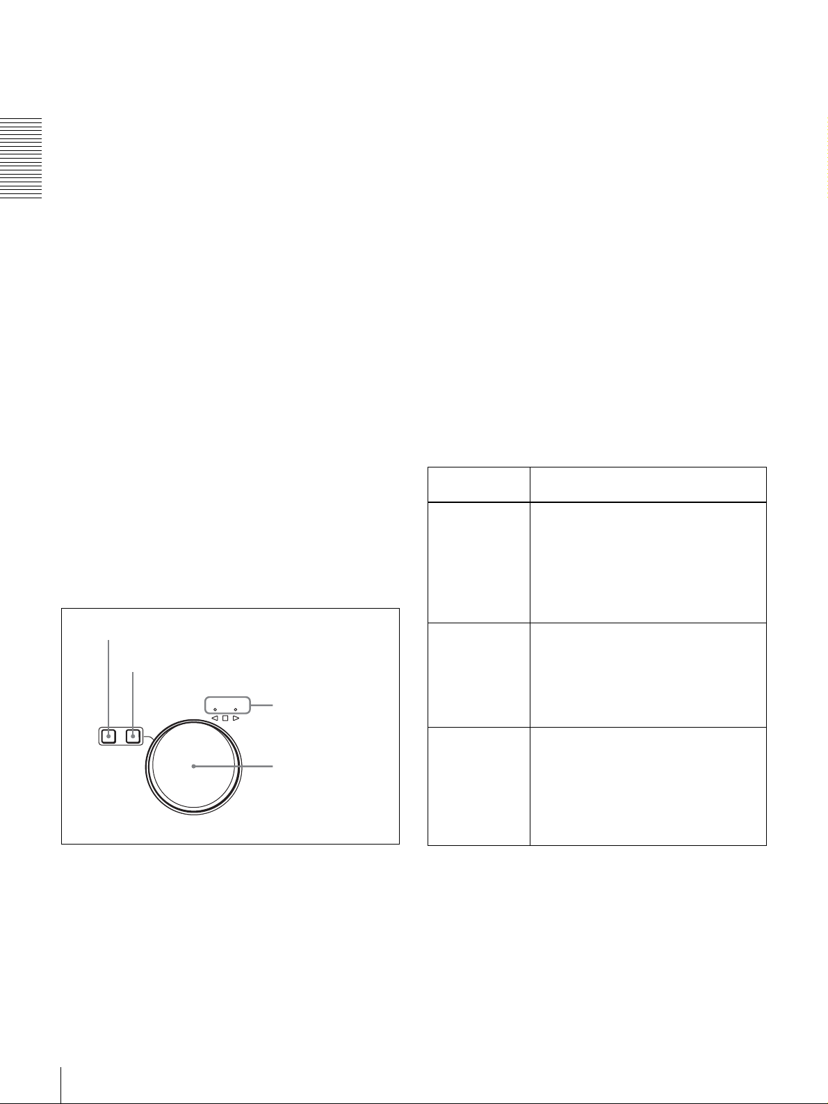
Front Panel
Chapter 1 Overview
a 1 switch
2 SC/SYNC control
3 Control mode
selector
4 PHONES connector
and control knob
5 METER CH-1/2 3/4 button
6 MONITOR SELECT button
qa Audio level meters
9 COUNTER SELECT button
8 LINE OUT SELECT button and indicators
7 CLIP button
0 Status indicators
1 Display section (see page 13)
2 Video/audio input setting section
(see page 15)
3 Audio input/output level control
section (see page 16)
4 Recording/playback control section
(see page 16)
a 1 (power) switch
Press to power on the unit when the POWER switch on the
rear panel is turned on (see page 19). This causes the audio
7 Search control section
6 Menu/clip control section (see page 17)
5 PANEL SELECT section
(see page 17)
(see page 18)
level meters and the display section to light. To power off
the unit, press the switch again.
10
Location and Function of Parts
b SC (subcarrier phase)/SYNC (synchronization
phase) control
Turn the SC control to accurately adjust the subcarrier
phase of the composite video output signal of the unit with
respect to the reference video signal.
c Control mode selector
Selects whether the unit is operated from its front panel or
from external equipment.
KEY INHI (key inhibit): All controls in the recording/
playback control section and the search control section
are disabled. In this state, the unit cannot be operated
from its front panel or from a remote control unit
connected to the CONTROL connector.
LOCAL: The unit is operated from its front panel or from
an RM-LG2 Remote Control Unit (supplied)
connected to the CONTROL connector.
REMOTE: The unit is operated from external equipment
connected to the REMOTE IN (R)/OUT (P)connectors
or S400(i.LINK) connector on the rear panel.
Select which of the connectors to use with the
REMOTE I/F menu item (see page 69).
Note
When you edit using the S400(i.LINK) connector,
with video and audio signal input set to i.LINK (see
page 15) and remote control set to 9PIN (see page 69),
the locations where edit points are actually set may not
be the same as the specified locations.
When you set video and audio signal input to i.LINK,
set remote control to i.LINK as well.
d PHONES connector (stereo phone jack) and
control knob
Connect stereo headphones to the connector for audio
monitoring during recording or playback. The control
knob controls the volume of the headphones. It also
controls the level of the audio signal output from the
MONITOR connector on the rear panel.
The settings made with the METER CH-1/2 3/4 button and
MONITOR SELECT button select the audio channels for
audio output via this connector. The same channel
selection as for the audio level meters applies to this
connector.
e METER CH-1/2 3/4 button
Pressing this button toggles the audio level meter mode
between CH-1/2 (channels 1 and 2) and CH-3/4 (channels
3 and 4).
The settings made with this button and the MONITOR
SELECT button select the channels for level indications
and audio output.
For more details, see “6 MONITOR SELECT button.”
f MONITOR SELECT button
Use this button and the METER CH-1/2 3/4 button to
select the audio channels:
• for level indications on the audio level meters
• for audio output via the PHONES connector on the front
panel
• for audio output via the MONITOR connector on the
rear panel
Depending on the setting made with the METER CH-1/2
3/4 button, the channels for output to the above meters and
connectors are selected as follows.
When CH-1/2 mode is selected with the METER CH-1/
2 3/4 button:
Audio level meters PHONES
connector
CH-1 (channel 1) only.
Only the left meter lights.
CH-2 (channel 2) only.
Only the right meter
lights.
CH-1 and CH-2 (channels
1 and 2).
Both the left and right
meters light.
Channel 1 only
(monaural)
Channel 2 only
(monaural)
Channels 1
and 2 (stereo)
MONITOR
connector
Channel 1 only
Channel 2 only
Channels 1
and 2 (mixed)
When CH-3/4 mode is selected with the METER CH-1/
2 3/4 button:
Audio level meters PHONES
connector
CH-3 (channel 3) only.
Only the left meter lights.
CH-4 (channel 4) only.
Only the right meter
lights.
CH-3 and CH-4 (channels
3 and 4).
Both the left and right
meters light.
Channel 3 only
(monaural)
Channel 4 only
(monaural)
Channels 3
and 4 (stereo)
MONITOR
connector
Channel 3 only
Channel 4 only
Channels 3
and 4 (mixed)
g CLIP button
This button is used for setting up and modifying clip lists,
and for clip segment playback operations.
See Chapter 4 for details about clip operations.
h LINE OUT SELECT button and indicators
When you are recording and playing back at the same time,
use this button to select output of playback or recording
signals. Each press of the button selects the other signals.
Recording signals are output when the R indicator is lit.
Playback signals are output when the P indicator is lit.
When the R indicator is lit: Recording signals are output.
When the P indicator is lit: Playback signals are output.
When both indicators are lit: Output signals are
recording signals or playback signals, as selected by
the R button and the P button in the PANEL SELECT
Chapter 1 Overview
Location and Function of Parts
11

section (see page 17). Output signals can also be
switched from an external device connected to the
REMOTE OUT(P) connector.
See “To select output signals during simultaneous
recording and playback” on page 35 for more information
about selecting the output during simultaneous recording
and playback.
Chapter 1 Overview
i COUNTER SELECT button
Selects the type of time data to be shown in the time
counter display. Each press of this button cycles through
the following three indicator display options:
• COUNTER (CNT: count value of the time counter)
• TC (time code)
• U-BIT (user bits)
Note
If the Control mode selector is set to REMOTE, the
COUNTER SELECT button does not operate. In this case,
make the time data selection via the external equipment
connected to the REMOTE IN (R)/OUT (P) connectors on
the rear panel.
j Status indicators
This indicate the current status of the unit.
CONTINUOUS REC: When this indicator is lit, the unit
will return to the first recording start position and
continue recording, overwriting old data, whenever
the available recording space is exhausted.
NETWORK: When the unit is connected to a LAN, this
indicator lights during data communications or on
standby for communication.
NEW CONTENTS: When the unit is connected to a
LAN, this indicator lights when new material is
received. The indicator goes out when the newly
received data is saved.
ACCESS: This indicator light when the hard disk is
accessed.
When CH-1/2 mode is selected with the METER CH-1/
2 3/4 button:
Every time the MONITOR SELECT button is pressed,
the audio channel selection for level indications on the
two meters cycles through the following options.
• CH-1 (channel 1) only
Only the CH-1 indicator lights.
• CH-2 (channel 2) only
Only the CH-2 indicator lights.
• CH-1 and CH-2 (channels 1 and 2)
Both the CH-1 and CH-2 indicators light.
When CH-3/4 mode is selected with the METER CH-1/
2 3/4 button:
Every time the MONITOR SELECT button is pressed,
the audio channel selection for level indications on the
two meters cycles through the following options.
• CH-3 (channel 3) only
Only the CH-3 indicator lights.
• CH-4 (channel 4) only
Only the CH-4 indicator lights.
• CH-3 and CH-4 (channels 3 and 4)
Both the CH-3 and CH-4 indicators light.
* E-E mode: Abbreviation of “Electric-to-Electric mode.” In this mode,
video and audio signals input to the VCR are output after passing through
internal electric circuits, but not through magnetic conversion circuits such
as heads and tapes. This can be used to check input signals and for
adjusting input signal levels.
Note
Do not power the unit off when the NETWORK indicator
or ACCESS indicator are lit. Doing so may result in the
loss of recorded or received data.
k Audio level meters
These two meters indicate the recording audio levels
during recording or EE mode* and the playback audio
levels during playback. When the audio level indicated on
a meter exceeds 0 dB, the OVER indicator for the meter
lights.
The short bars to the right of level indication bars indicate
that those levels are reference audio recording levels.
The settings made with the METER CH-1/2 3/4 button and
MONITOR SELECT button select the audio channels for
level indications on these meters as follows.
12
Location and Function of Parts
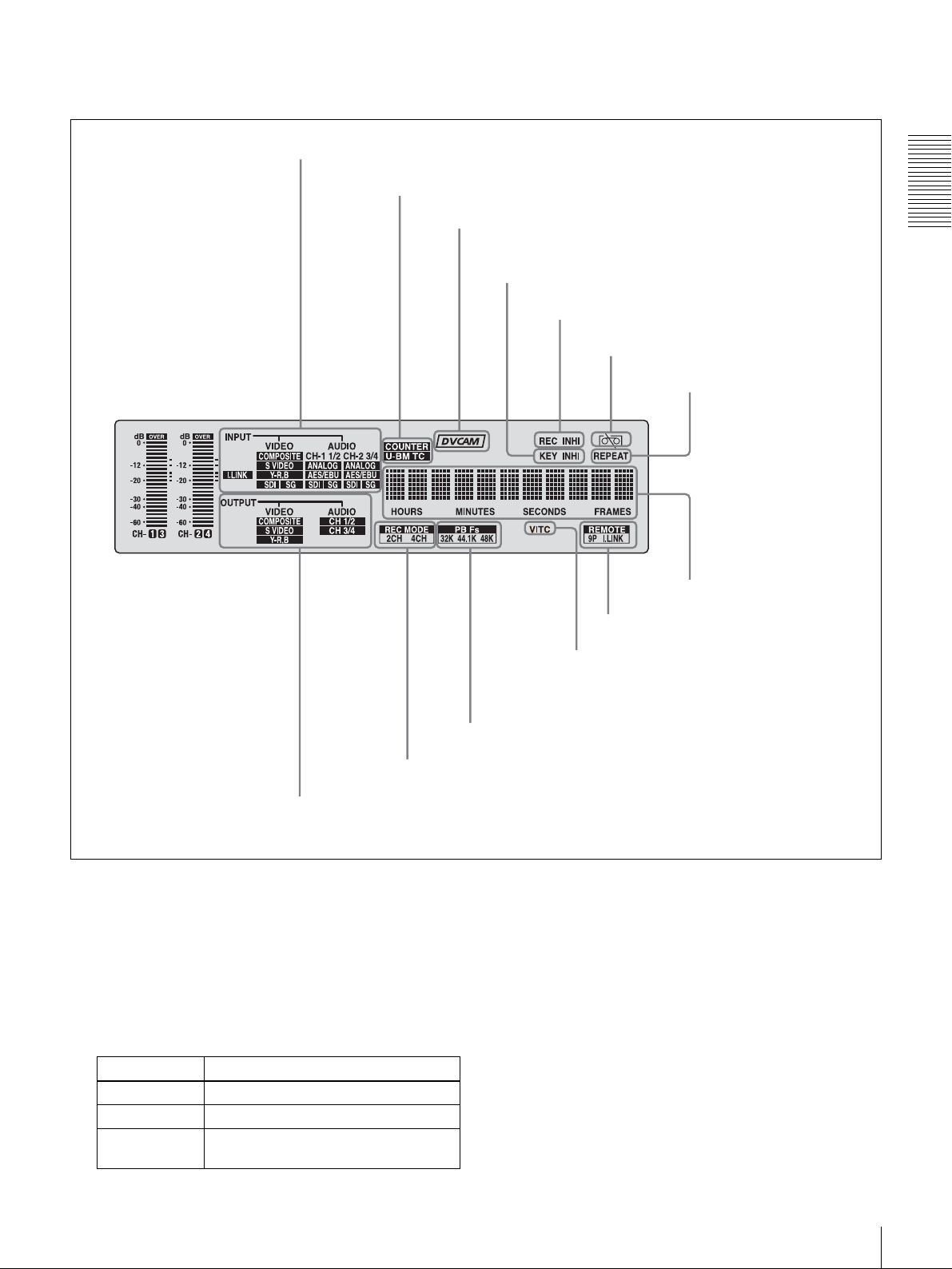
1 Display section
2 INPUT signal display section
3 Time data type indicators
4 DVCAM indicator
5 KEY INHI indicator
6 REC INHI indicator
Chapter 1 Overview
7 Disk end alarm indicator
8 REPEAT indicator
9 Time counter display
0 Remote mode indicators
qa VITC indicator
qd REC MODE display
1 OUTPUT signal display section
a OUTPUT signal display section
Indicates the output video and audio signal format selected
with the INTERFACE SELECT menu items (see page 69).
VIDEO indicators: The indicator (COMPOSITE, S
VIDEO, or Y
−R,B) corresponding to the selected
output analog video signal format lights.
Indicators Meanings
COMPOSITE Composite video signal
S VIDEO S-video (separated Y and C) signals
Y−R,B Y, R−Y and B−Y component video
signals
qs PB Fs display
This selection determines the signals output from the
Y/CPST, R
connectors as follows.
−Y/S−C, and B−Y/S−Y, SUPER
Location and Function of Parts
13
• When COMPOSITE/S VIDEO is selected:
Connectors Output signals
Y/CPST Composite signal
R−Y/S−CS−C
B−Y/S−YS−Y
SUPER Composite signal
Chapter 1 Overview
• When Y
Connectors Output signals
Y/CPST Y signal
R−Y/S−CR−Y signal
B−Y/S−YB−Y signal
SUPER Composite signal
–R,B is selected:
AUDIO indicators: Comprise the CH 1/2 indicator and
CH 3/4 indicator to indicate the channel selection for
analog audio output from the AUDIO OUT 1/3 and
AUDIO OUT 2/4 connectors.
Indicators Functions
CH 1/2 Lights when channels 1 and 2 are
selected for analog audio output from
the AUDIO OUT 1/3 and AUDIO OUT
2/4 connectors
CH 3/4 Lights when channels 3 and 4 are
selected for analog audio output from
the AUDIO OUT 1/3 and AUDIO OUT
2/4 connectors
.
.
You can change the channel selection with the AUDIO
OUTPUT menu item (see page 69).
b INPUT signal display section
Indicates the input video and audio signal formats selected
with the INPUT SELECT buttons (i.LINK, VIDEO, CH1
1/2, and CH2 3/4 buttons).
i.LINK indicator: Lights when the digital video and audio
signals in i.LINK-compatible DV format are selected.
VIDEO indicators: The indicator (COMPOSITE, S
VIDEO, Y
−R,B, SDI, or SG) corresponding to the
selected input video signal format lights.
Indicators Meanings
COMPOSITE Composite video signal
S VIDEO S-video (separated Y and C) signals
Y−R,B Y, R−Y and B−Y component video
signals
SDI SDI video signal
SG Video test signal (factory default
setting)
AUDIO indicators: Comprise the CH-1 1/2 indicator and
CH-2 3/4 indicator, under each of which there are four
more indicators (ANALOG, AES/EBU, SDI, and SG).
They indicate the selected input audio signal formats.
Indicators Functions
CH-1 1/2
(ANALOG, AES/
EBU, SDI, SG)
CH-2 3/4
(ANALOG, AES/
EBU, SDI, SG)
Note
The indicator corresponding to the
signal format selected for audio input
to channel 1 (when in 2-channel
mode) or to channels 1 and 2 (when
in 4-channel mode) lights.
ANALOG: Analog audio signal
AES/EBU: Digital audio signal in
AES/EBU format
SDI: SDI audio signal
SG: Audio test signal (factory default
setting)
The indicator corresponding to the
signal format selected for audio input
to channel 2 (when in 2-channel
mode) or to channels 3 and 4 (when
in 4-channel mode) lights.
ANALOG: Analog audio signal
AES/EBU: Digital audio signal in
AES/EBU format
SDI: SDI audio signal
SG: Audio test signal (factory default
setting)
The indicators blink if no signals are connected to the
selected video/audio input connectors.
c Time data type indicators
One of the three indicators (COUNTER, U-BIT, or TC)
lights to indicate the type of time data currently shown in
the time counter display.
COUNTER: Count value of the time counter
U-BIT: User bit data
TC: SMPTE time code (for DSR-DR1000A) or EBU time
code (for DSR-DR1000AP)
d DVCAM indicator
This stays lit.
e KEY INHI (key inhibit) indicator
Lights when the control mode selection switch is set to
KEY INHI.
f REC INHI (recording inhibit) indicator
Lights when the REC INHIBIT menu item (see page 62) is
set to ON.
g Disk end alarm indicator
Starts flashing when the remaining capacity of the disk is
for about 2 minutes.
h REPEAT (repeat playback) indicator
Lights when the REPEAT MODE menu item (see page
61) is set to ON to enable the repeat playback function.
i Time counter display
Indicates the count value of the time counter, time code,
VITC, or user bit data depending on the settings of the
14
Location and Function of Parts

COUNTER SELECT button and the TC SELECT menu
item (see page 65).
Also used to display error messages, edit data, setup menu
data, etc.
j Remote mode indicators
REMOTE: Lights when the Control mode selector is set
to REMOTE to remote control the unit from either an
editing control unit connected to the REMOTE IN (R)/
OUT (P) connectors or equipment connected to the
S400(i.LINK) connector.
9P: Lights when the REMOTE I/F menu item (see page
69) is set to 9PIN.
i.LINK: Lights when the REMOTE I/F menu item (see
page 69) is set to i.LINK.
k VITC indicator
Lights when VITC is being read or recorded regardless of
the data shown in the time counter display.
l PB Fs (playback audio sampling frequency) display
During playback, this indicates the playback audio mode
in which the disk being played back was recorded.
48K indicator: Lights during playback of material
recorded in 2-channel mode (48 kHz).
32K indicator: Lights during playback of material
recorded in 4-channel mode (32 kHz).
m REC MODE (audio recording mode) display
This indicates the audio recording mode currently selected
with the REC MODE menu item (see page 68).
2CH indicator: Lights in 2-channel mode (48 kHz).
4CH indicator: Lights in 4-channel mode (32 kHz).
2 Video/audio input setting section
INPUT SELECT
CH1 1/2 CH2 3/4
3 CH2 3/4 button
2 CH1 1/2 button
1 VIDEO button
a VIDEO button
Each press of this button cycles through the following
input video signal selection options.
• Composite video signal input to the VIDEO IN
connector
• S-video (separated Y and C) signals input to the VIDEO
IN connectors
−Y and B−Y component video signals input to the
•Y, R
VIDEO IN connectors
• SDI video signal input to the SDI IN connector
• Video test signal (selected with the INT VIDEO SG
menu item (see page 66) generated by the internal signal
generator
• Digital video/audio signal (DV format, complied with
i.LINK) connected to the S400(i.LINK) connector
The selection made with this button is indicated by the
i.LINK/VIDEO indicators in the INPUT signal display
section (see page 14).
Chapter 1 Overview
Note
When the video input is set to the i.LINK, pressing either
the CH1 1/2 button or CH2 3/4 button changes the setting
to COMPOSITE. Reset the video input.
b CH1 1/2 (audio channel 1 or 1/2) button
Each press of this button cycles through the following
input audio signal selection options for audio channel 1
(when in 2-channel mode) or for audio channels 1 and 2
(when in 4-channel mode).
• Analog audio signal input to the AUDIO IN 1/3
connector
• Digital audio signal in AES/EBU format input to the
AUDIO (AES/EBU) IN 1/2 connector
• SDI audio signal input to the SDI IN connector
• Audio test signal (selected with the INT AUDIO SG
menu item (see page 69) generated by the internal signal
generator
The selection made with this button is indicated by the
AUDIO CH-1 1/2 indicators in the INPUT signal display
section (see page 14).
When analog audio is selected, the signal input to the
AUDIO IN 1/3 connector is recorded either on channel 1
(when in 2-channel mode) or on channels 1 and 3 (when in
4-channel mode). That is, in 4-channel mode, the same
analog audio signal is recorded on channels 1 and 3. Using
the REC/PB LEVEL control knobs with the VARIABLE
switch set to REC, it is possible to adjust the audio levels
on the two channels separately.
You can switch the audio recording mode with the REC
MODE menu item (see page 68). The selection is indicated
by the REC MODE display on the front panel.
c CH2 3/4 (audio channel 2 or 3/4) button
Each press of this button cycles through the following
input audio signal selection options for audio channel 2
(when in 2-channel mode) or for audio channels 3 and 4
(when in 4-channel mode).
• Analog audio signal input to the AUDIO IN 2/4
connector
• Digital audio signal in AES/EBU format input to the
AUDIO (AES/EBU) IN 3/4 connector
• SDI audio signal input to the SDI IN connector
• Audio test signal (selected with the INT AUDIO SG
menu item (see page 69) generated by the internal signal
generator
Location and Function of Parts
15
The selection made with this button is indicated by the
AUDIO CH-2 3/4 indicators in the INPUT signal display
section (see page 14).
When analog audio is selected, the signal input to the
AUDIO IN 2/4 connector is recorded either on channel 2
(when in 2-channel mode) or on channels 2 and 4 (when in
4-channel mode). That is, in 4-channel mode, the same
analog audio signal is recorded on channels 2 and 4. Using
the REC/PB LEVEL control knobs with the VARIABLE
Chapter 1 Overview
switch set to REC, it is possible to adjust the audio levels
on the two channels separately.
You can switch the audio recording mode with the REC
MODE menu item (see page 68). The selection is indicated
by the REC MODE display on the front panel.
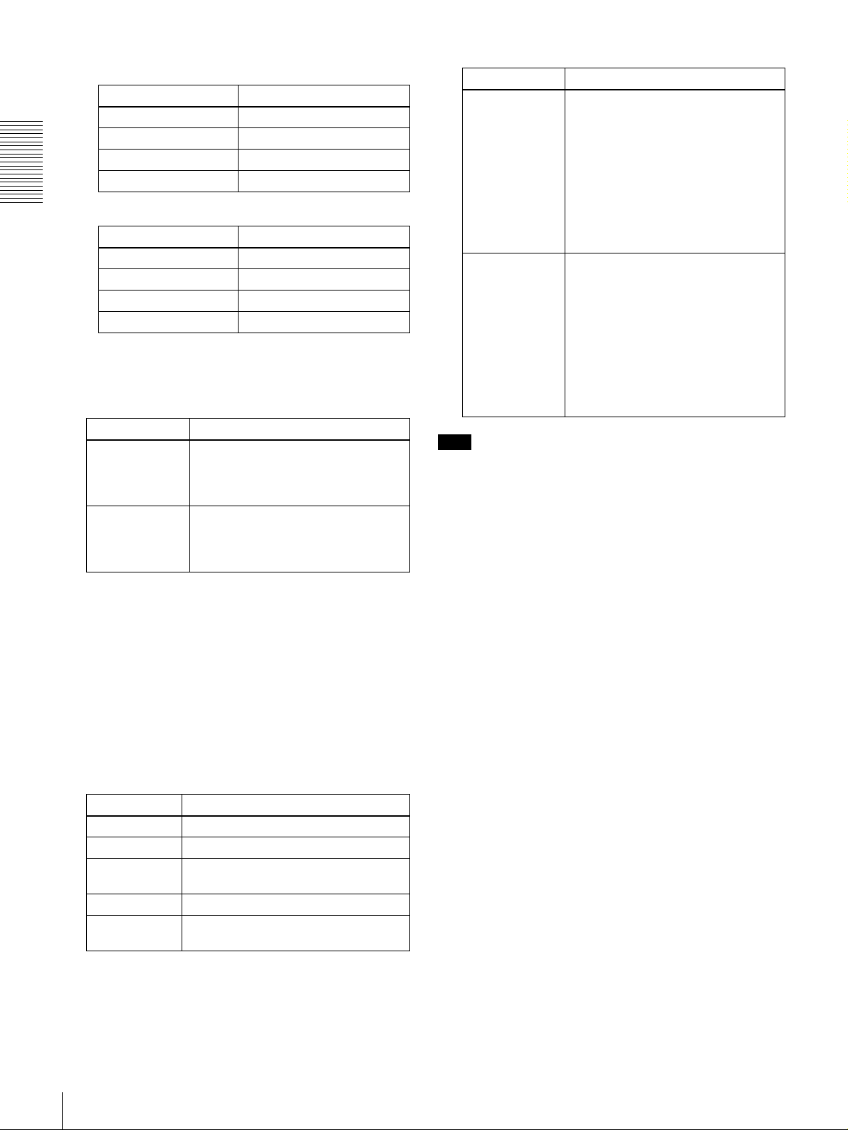
3 Audio input/output level control section
1 VARIABLE switch
2 REC/PB LEVEL
control knobs
VARIABLE
REC
PB
PRESET
a VARIABLE switch
Use to switch the way in which the REC/PB LEVEL
control knobs function.
REC/PB LEVEL
1 2 3 4
Note
If you set the VARIABLE switch to REC, set the audio
input levels, and then set the switch to PB, the audio input
levels return to the preset levels. In the same way if you set
VARIABLE switch to PB, set the audio output levels, and
then set the switch to REC, the audio output levels return
to the preset levels.
b REC/PB LEVEL control knobs
These knobs are used to control audio levels function
differently depending on the setting of the VARIABLE
switch as follows.
VARIABLE
switch
setting
PRESET Control knobs are not effective.
REC Control the analog/digital audio input levels on
PB Control the analog/digital audio output levels
Functions of control knobs
The analog audio input/output levels are set to
the reference level set with the LEVEL
SELECT menu item (see page 68).
The digital audio input/output levels are not
adjusted.
channels 1 to 4 during recording.
The audio output levels return to the preset
levels.
on channels 1 to 4 during playback.
The audio input levels return to the preset
levels.
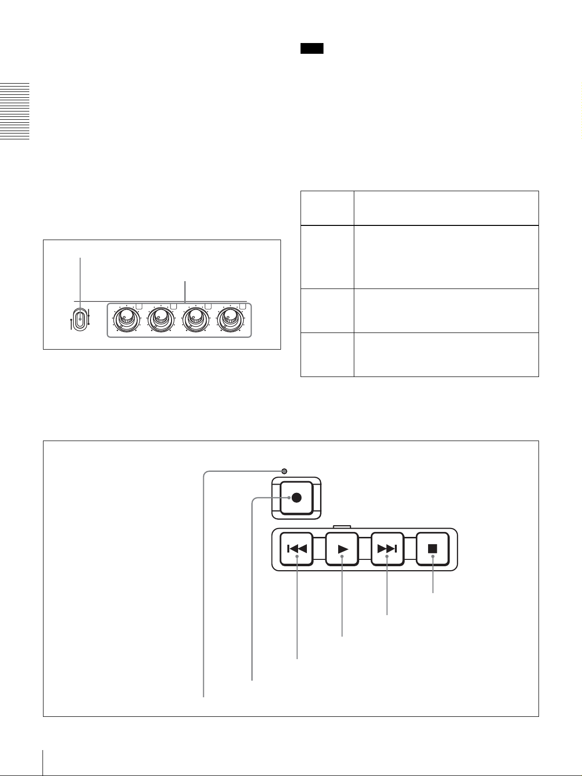
4 Recording/playback control section
2 REC button
REC
PLAY
3 PREV button
STOPNEXT
6 STOP button
5 NEXT button
4 PLAY button
16
Location and Function of Parts
1 REC indicator

a REC (record) indicator
Lights during recording.
b REC (record) button
When you press this button while holding down the PLAY
button, it lights and recording begins.
PANEL SELECT
RP
EXT
Note
When the control mode selector is set to REMOTE (the
REMOTE indicator is lit), no recording/playcack control
buttons other than the STOP button will work. This can be
changed with the LOCAL ENABLE menu item (see page
62).
c PREV (previous) button
When pressed once, moves to the start point of the clip
containing the current position. When pressed a second
time, moves to the start point of the previous clip.
Pressing the PREV button with the PLAY button held
down allows you to view fast reverse playback. However,
to do this, you need to set the F. FWD/REW menu item
under the AUTO EE SELECT menu item (see page 61) to
PB.
If cue points are set (see page 33), the PREV button is used
to cue up a cue point (see page 41).
d PLAY button
When you press this button, it lights and playback begins.
If you press this button during recording, the recording
operation is stopped and this unit enters playback mode.
e NEXT button
When pressed once, moves to the start point of the next
clip. However, when this button is pressed while in the last
clip, it moves to the end point of that clip.
Pressing the NEXT button with the PLAY button held
down allows you to view fast forward playback. However,
to do this, you need to set the F. FWD/REW menu item
under the AUTO EE SELECT menu item (see page 61) to
PB.
If cue points are set (see page 33), the NEXT button is used
to cue up a cue point (see page 41).
f STOP button
Press this button to stop the recording or playback
operation.
3 EXT button
2 P button
1 R button
a R (recorder) button
Press this button, turning it on, to put the control panel of
the unit into a state in which the only operations possible
are recording operations. The buttons which function in
this state are the REC button, PLAY button (only when
pressed at the same time as the REC button), and the STOP
button.
b P (player) button
Press this button, turning it on, to put the control panel of
the unit into a state in which the only operations possible
are playback operations. The REC button and PLAY
button do not function, even if pressed at the same time.
c EXT (external) button
When you have connected multiple DSR-DR1000A/
DR1000AP units in a cascade sequence and want to
control the other units from a one unit, press the EXT
button of the controlling unit, turning it on.
You can connect multiple DSR-DR1000A/DR1000AP units
for multi-simultaneous playback. For details, see
“Connecting Multiple Units for Simultaneous Playback
(Multi-Simultaneous Playback)” on page 39.
6 Menu/clip control section
1 MENU button
2 RESET button
MENU RESET SET
3 SET button
Chapter 1 Overview
5 PANEL SELECT section
Note
The buttons of the PANEL SELECT section cannot be
turned on or off during simultaneous recording and
playback.
a MENU button
Press this button to display the menu on the monitor screen
CUE
IN OUT
4 Cursor/clip operation
buttons
and the time counter display. Press it again to exit the menu
display.
Location and Function of Parts
17
On how to use the menu, see Chapter 6 “Menu Setting”
b RESET button
Press this button to:
• reset menu settings,
• reset the time data shown in the time counter display to
zero
• send a negative response to the prompts issued by the
unit, or
Chapter 1 Overview
• delete clips.
c SET button
Press this button to:
• save new settings, such as selected menu items and time
code settings, to memory.
• send a positive response to the prompts issued by the
unit, or
• create a clip list.
d Cursor/clip operations buttons
Press these buttons to select a menu item, to change
timecode initial values and user bits data, and to set clip in
and out points, and to set cue points.
K (IN): Moves to the left or sets an in point.
J (CUE): Moves up or sets a cue point.
k (OUT): Moves right or sets an out point.
j: Moves down.
For details on modifying the time code value, see “To set
the initial time code value and user bit data” on page 27.
7 Search control section
1 SEARCH button
2 VAR button
JOG SHUTTLE
SEARCH VAR
3 JOG and SHUTTLE
indicators
4 Search dial
b VAR (variable) button
Press this button, turning it on, to use the search dial for
search playback in variable mode.
See the description of the search dial 4 for more
information about the variable mode.
c JOG and SHUTTLE indicators
One of the indicators lights to show the current or most
recent search playback mode.
JOG indicator: Jog mode
SHUTTLE indicator: Shuttle or variable mode.
d Search dial
Rotate to perform search playback in jog shuttle, or
variable mode.
The G indicator lights when you rotate to the right to
indicate forward direction playback. The g indicator lights
when you rotate to the left to indicate reverse direction
playback. The s indicator lights when playback is
stopped. The s lights when unit is powered on.
Each press of the search dial toggles between shuttle and
jog mode, or between variable mode and jog mode.
Search
playback mode
Shuttle Press the SEARCH button or the search
Jog Press the SEARCH button or the search
Variable Press the VAR button, lighting it (the
Operation/function
dial to select shuttle mode (the SHUTTLE
indicator lights). Playback is carried out
at a speed determined by the rotation
angle of the search dial.
The maximum shuttle playback speed
can be changed with the MAX SRCH
SPEED menu item (see page 62).
dial to select jog mode (the JOG indicator
lights). Playback is carried out at a speed
determined by the rotation speed of the
search dial. The playback sped range is
±1 times normal speed. The search dial
does not click in this mode.
SHUTTLE indicator also lights). You can
control fine-grained (in 61 steps)
playback over the range (2 times normal
speed. The search dial clicks in the
positions for still playback, ±1 times
normal speed, and ±2 times normal
speed.
a SEARCH button
Press this button, turning it on, to use the search dial for
search playback in jog or shuttle mode.
See the description of the search dial 4 for more
information about the jog and shuttle modes.
18
Location and Function of Parts

Rear Panel
1 REF. VIDEO IN connectors
1 Analog video/audio signal
4 CONTROL connecter
input section
(see page 20)
2 Analog video/audio signal
output section
(see page 21)
3 Digital signal input/output
section (see page 22)
2 POWER switch
3 -AC IN connector
Chapter 1 Overview
5 REMOTE IN (R)/OUT (P) connectors
6 S400 (i.LINK) connector
7 Network connecter
4 Time code input/output section (see page 23)
a REF. (reference) VIDEO IN connectors (BNC
type)
Input a reference video signal. The two connectors are
loop-through connectors. You can connect the reference
video signal input to the left connector to other equipment
via the right connector (marked ). When no connection
is made to the right connector, the left connector is
terminated with an impedance of 75 Ω automatically.
b POWER (main power) switch
Switch to the ? side to turn the power on. Switch to the a
side to turn the power off. Normally you should leave this
switch in the on position and power the unit on and off with
the power switch on the front panel.
Note
When you power the unit off with the switch on the front
panel, data is saved before the power is cut off. If you need
to turn the main power off, always power the unit off with
the switch on the front panel before setting this switch to
off.
c - AC IN connector
Use the supplied power cord to connect this to an AC
outlet.
d CONTROL connector (mini-jack)
Connect the supplied RM-LG2 Remote Control Unit.
e REMOTE IN (R)/OUT (P) connectors (D-sub 9-
pin)
You can connect remote control units to these connectors
using an optional 9-pin remote cable. You can also use this
connectors to make cascade connections between several
DSR-DR1000A/DR1000AP units.
Use the IN(R) connector to connect an editor. When
connecting remote control devices, connect the device that
controls recording operations to the IN(R) connector and
the device that controls playback operations to the OUT(P)
connector.
Before doing this, you need to set the REMOTE I/F menu
item (see page 69) to select how the connectors are used.
Location and Function of Parts
19

f S400 (i.LINK) connector (6-pin IEEE-1394)
Connect a DV cable to make connections to DV devices,
computers, and so on.
Notes
• If the unit is connected to a device equipped with a 6-pin
DV jack, when you intend to disconnect or reconnect the
DV cable, turn off the device and pull out the plug of its
power cord from the AC outlet beforehand. If you
Chapter 1 Overview
connect or disconnect the DV cable while the device is
connected to the AC outlet, high-voltage current (8 to 40
V) is output from the DV jack of the device to this unit,
which may cause a malfunction.
• When connecting a device that has a 6-pin DV jack to
this unit, first connect the plug of the cable to the 6-pin
DV jack of the device.
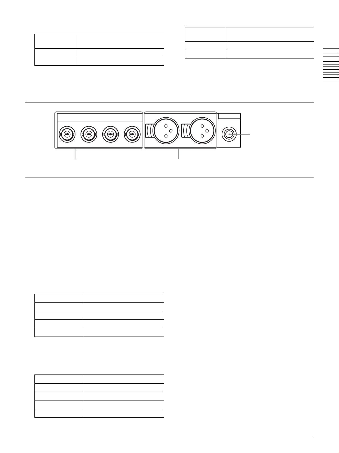
1 Analog video/audio signal input section
1
• When searching at speeds in the range +
1
−
/30 to −1/2 times normal speed, the audio signal output
/2 to +1/30 or
from this connector and monitored on external
equipment may sound differently from the audio signal
played back on this unit.
g (network) connector (RJ-45 type)
This is a 10BASE-T/100BASE-TX connector for network
(Ethernet) connection.
CAUTION
For safety, do not connect the connector for peripheral
device wiring that might have excessive voltage to this
port. Follow the instructions in this manual when making
connections.
Y/CPST
1 VIDEO IN connectors
VIDEO IN
R-Y/C
B-Y
1/3 2/4
a VIDEO IN connectors (BNC type)
There are the following VIDEO IN connectors for
inputting analog video signals:
• Y/CPST (loop-through connectors)
−Y/C
•R
−Y
•B
The signals you can connect to these connectors depend on
the selection made with the VIDEO button in the video/
audio input selection section. The selection is indicated by
the VIDEO indicators in the INPUT signal display section.
The analog video signals that can be input to these
connectors are as follows.
When COMPOSITE is selected:
Connectors Input signals
Y/CPST Composite signal
R−Y/C — (not usable)
B−Y — (not usable)
The two Y/CPST connectors are loop-through
connectors. When using the signal input to the left Y/
CPST connector as a reference video signal, for
example, you can bridge-connect the signal to other
equipment via the right Y/CPST connector (marked
). When no connection is made to the right Y/
AUDIO IN
2 AUDIO IN 1/3 and AUDIO IN
2/4 connectors
CPST connector, the left Y/CPST connector is
terminated with an impedance of 75 Ω automatically.
When S VIDEO is selected:
Connectors Input signals
Y/CPST Y signal
R−Y/C C signal
B−Y — (not usable)
When Y
–R,B is selected:
Connectors Input signals
Y/CPST Y signal
R−Y/C R−Y signal
B−YB−Y signal
(3.58 MHz for DSR-DR1000A/
4.43 MHz for DSR-DR1000AP)
b AUDIO IN 1/3 and AUDIO IN 2/4 connectors
(XLR-3 pin, female)
Use these connectors to input analog audio signals from an
external video cassette player or other audio equipment.
The signals input to these connectors are recorded on the
audio channels determined by the current audio recording
mode, as follows.
20
Location and Function of Parts
When in 2 CH (48 kHz) mode:
Input
connectors
AUDIO IN 1/3 Audio channel 1
AUDIO IN 2/4 Audio channel 2
Audio channels on which input
signals are recorded
When in 4 CH (32 kHz) mode:
2 Analog video/audio signal output section
Input
connectors
AUDIO IN 1/3 Audio channels 1 and 3
AUDIO IN 2/4 Audio channels 2 and 4
Audio channels on which input
signals are recorded
You can switch the audio recording mode with the REC
MODE menu item (see page 68). The selection is indicated
by the REC MODE display on the front panel.
Chapter 1 Overview
Y/CPST
VIDEO OUT
R-Y/S-C B-Y/S-Y
1 VIDEO OUT connectors
SUPER
1/3 2/4
a VIDEO OUT connectors (BNC type)
There are the following VIDEO OUT connectors for
outputting analog video signals:
•Y/CPST
−Y/S−C
•R
−Y/S−Y
•B
•SUPER
The signals output from these connectors depend on the
setting of the VIDEO OUTPUT menu item (see page 69).
The setting is indicated by the VIDEO indicators in the
OUTPUT signal display section on the front panel.
The analog video signals that can be output from these
connectors are as follows.
AUDIO OUT
MONITOR
3 MONITOR
connector
2 AUDIO OUT 1/3 and
AUDIO OUT 2/4
connectors
* When the CHARA. DISPLAY menu item (see page 63) is set to ON
(factory default setting), the SUPER connector outputs a composite
video signal with superimposed text information.
b AUDIO OUT 1/3 and AUDIO OUT 2/4 connectors
(XLR-3 pin, male)
These connectors output analog audio signals. The output
audio channels are determined by the playback audio mode
and the setting (1/2 CH or 3/4 CH) of the AUDIO
OUTPUT menu item (see page 69) as follows.
When COMPOSITE/S VIDEO is selected:
Connectors Output signals
Y/CPST Composite signal
R−Y/S−CS−C
B−Y/S−YS−Y
SUPER* Composite signal
* When the CHARA. DISPLAY menu item (see page 63) is set to ON
(factory default setting), the SUPER connector outputs a composite
video signal with superimposed text information.
When Y–R, B is selected:
Connectors Output signals
Y/CPST Y signal
R−Y/S−CR−Y signal
B−Y/S−YB−Y signal
SUPER* Composite signal
Location and Function of Parts
21
When in 2 CH (48 kHz or 44.1 kHz) mode:
Output
connectors
AUDIO OUT 1/3 Audio channel 1 (when 1/2 CH is
AUDIO OUT 2/4 Audio channel 2 (when 1/2 CH is
Chapter 1 Overview
Output audio channels
selected) or silent (when 3/4 CH is
selected)
selected) or silent (when 3/4 CH is
selected)
When in 4 CH (32 kHz) mode:
Output
connectors
AUDIO OUT 1/3 Audio channel 1 (when 1/2 CH is
Output audio channels
selected) or audio channel 3 (when 3/
4 CH is selected)
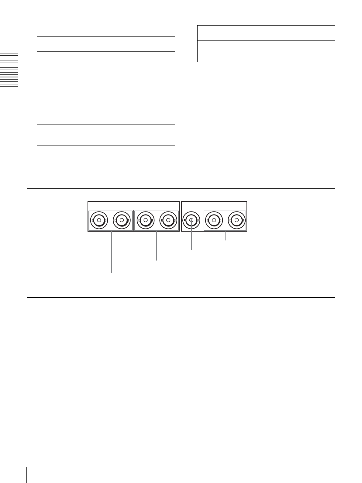
3 Digital signal input/output section
Output
connectors
AUDIO OUT 2/4 Audio channel 2 (when 1/2 CH is
Output audio channels
selected) or audio channel 4 (when 3/
4 CH is selected)
The current playback audio mode is indicated by the PB Fs
display on the front panel.
c MONITOR connector (RCA phono jack)
This connector outputs audio signals for monitoring. The
audio signals to be output from this connector can be
selected with the MONITOR SELECT button and
METER CH-1/2 3/4 button on the front panel (see page
11).
DIGITAL AUDIO
1 DIGITAL AUDIO (AES/EBU) IN 1/2 and AUDIO
(AES/EBU) IN 3/4 connectors
(AES/EBU)
1/2 - OUT - 3/41/2 - IN - 3/4
2 DIGITAL AUDIO (AES/EBU) OUT 1/2 and
AUDIO (AES/EBU) OUT 3/4 connectors
a DIGITAL AUDIO (AES/EBU) IN 1/2 and AUDIO
(AES/EBU) IN 3/4 connectors (BNC type)
Input digital audio signals in AES/EBU format to these
connectors.
The left connector (1/2) is for audio channels 1 and 2, and
the right connector (3/4) is for audio channels 3 and 4.
b DIGITAL AUDIO (AES/EBU) OUT 1/2 and
AUDIO (AES/EBU) OUT 3/4 connectors (BNC
type)
These connectors output digital audio signals in AES/EBU
format.
The left connector (1/2) is for audio channels 1 and 2, and
the right connector (3/4) is for audio channels 3 and 4.
IN
3 SDI IN connector
SDI
OUT1 OUT2
4 SDI OUT1/OUT2 connectors
input setting section (see page 15) to select the required
input signal formats. The current input signal selections
are indicated in the INPUT signal display section (see page
14).
d SDI OUT1/OUT2 (Serial Digital Interface output
1/output 2) connectors (BNC type)
These connectors output digital video and audio signals in
SDI format.
c SDI IN (Serial Digital Interface input) connector
(BNC type)
This connector inputs digital video and audio signals in
SDI format. Use the VIDEO button in the video/audio
22
Location and Function of Parts

D Time code input/output section
1 TIME CODE IN connector
2 TIME CODE OUT connector
TIME CODE
IN OUT
a TIME CODE IN (time code input) connector (BNC
type)
Input externally generated SMPTE time code (for DSRDR1000A) or EBU time code (for DSR-DR1000AP) to
this connector.
b TIME CODE OUT (time code output) connector
(BNC type)
This connector outputs a time code according to the
operating state of the unit, as follows:
During playback: the playback time code
During recording: the time code generated by the internal
time code generator or the time code input to the TIME
CODE IN connector. When the EE OUT PHASE
menu item (see page 66) is set to MUTE, no time code
is output.
Chapter 1 Overview
Location and Function of Parts
23

Preparations
Setting the Date and Time
When you start this unit for the first time, you should set
the data and time. To set the date and time, use the DATE/
TIME PRESET menu.
See page 72 for more information about basic menu
operations.
DATE/TIME PRESET
DATE 2002/07/10
TIME 18:29:10
INC/DEC : ( )( )KEY
SHIFT : ( )( )KEY
CLEAR : RESET KEY
DATA SAVE : SET KEY
TO MENU : MENU KEY
Chapter
To change a numeric value
Press the J(CUE) button to increase a value. Press the j
button to decrease a value.
To return a value to the factory default setting (2002/01/01
00: 00: 00) press the RESET button.
To confirm a value
Press the SET button.
To exit the date and time setting menu without changing
any values, press the MENU button.
To display the material’s recording date
and time on the monitor
This unit records time code and the recording date and time
together with video data. To the material's recording date
and time on the monitor, set the DISPLAY INFO menu
item (see page 63) to REC DATE&TIME.
To select the digit to set
Press the K(IN) or k(OUT) button until the digit you
want to change starts flashing. (In the date display, the
digit in the second place from the left does not flash).
To move from the date display to the time display, press
the k(OUT) button while the rightmost digit is flashing
(the leftmost digit of the time display begins to flash), or
press the K(IN) button while the third place from the left
(the + position) is flashing (the rightmost digit of the time
display begins to flash).
To move from the time display to the date display, press
the k(OUT) button while the rightmost digit is flashing
(the third place of the date display begins to flash), or press
the K(IN) button while the leftmost digit is flashing (the
rightmost digit of the date display begins to flash).
Setting the Time Data
This unit is provided with the following functions related
to time data.
• Display and reset CNT value
• Set, display, record, and play back SMPTE/EBU time
code and user bit data
• Set, display, record, and play back VITC
The unit can output the time code read from the disk as an
analog (LTC) signal, and receive an external analog time
code (LTC) signal.
Note
The unit outputs no signal from the TIME CODE OUT
connector unless it is in normal-speed playback mode.
The following explains how to use these functions.
24
Setting the Date and Time / Setting the Time Data
Displaying Time Data and Operation
Mode Indications
Time data and operation mode indications can be
displayed on the monitor screen.
Time data can also be displayed in the time counter display
on this unit.
To view time data and operation mode
indications on the monitor screen
Set the CHARA. DISPLAY menu item (see page 63) to
ON (factory default setting).
The time data and the indication of the current operation
mode are superimposed on the video signal that is being
output from the SUPER connector, and can be viewed on
the monitor screen.
Use the DISPLAY CONTROL menu items (see page 63)
to select the information displayed and the character type
and position of the indications.
When you set the SUB STATUS menu item (see page 64)
to other than OFF, you can also display supplementary
status information on the monitor screen such as the
operating mode of the internal time code generator.
Indication Description
CNT Count value of the time counter
TCR Time code data from time code reader
(factory default setting)
UBR User bit data from time code reader
TCR.
UBR.
TCG Time code data from time code generator
UBG User bit data from time code generator
b)
T*R
b)
U*R
a) You can switch between TC and VITC using the TC SELECT menu item
(see page 65).
b) “*” is displayed when data cannot be read in correctly.
Time code data from VITC reader
User bit data from VITC reader
Time code data from time code reader. The
asterisk indicates an interpolation by the time
code reader to make up for the time code
data not correctly read from the disk.
User bit data from the time code reader. The
asterisk indicates that last data is retained by
the time code reader, as the new data has
not been read correctly from the disk.
a)
a)
B Drop frame indication for time code reader (on
DSR-DR1000A only)
Chapter 2 Preparations
For details of supplementary status information, see
“Displaying Supplementary Status Information” on page
76.
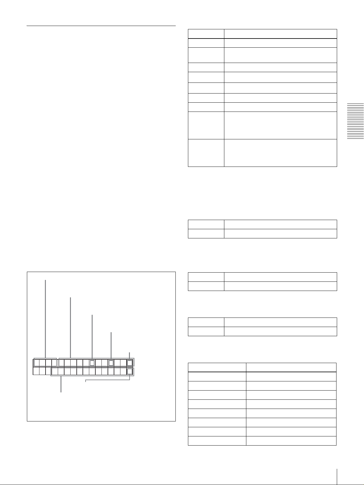
Monitor screen contents
The contents of the monitor screen are shown below.
A Time data type
Time data
B Drop frame indication
for time code reader
C Drop frame indication for
time code generator
TCR
a) This character (.) can appear on the DSR-DR1000A only. The
character to appear in these two columns is always a colon
( : ) on the DSR-DR1000AP.
00 : 04 47.07*
PLA
Y
F Recording indications during
E DSR-DR1000A/DR1000AP operation mode
simultaneous playback and recording
.
a)
D VITC field
indication
a)
A Time data type
The following time data type indications are displayed.
. Drop frame mode (factory default setting)
: Non-drop frame mode
C Drop frame indication for time code generator
(for DSR-DR1000A only)
. Drop frame mode (factory default setting)
: Non-drop frame mode
D VITC field indication
(blank) Display fields 1 and 3.
* Display fields 2 and 4.
E DSR-DR1000A/DR1000AP operation mode
Display Operation mode
STOP Stop mode
F. FWD Fast forward mode
REW Rewind mode
PREROLL Preroll mode
PLAY Playback mode (servo unlocked)
PLAY-PAUSE Temporary stop of playback
PLAY LOCK Playback mode (servo locked)
REC Record mode (servo unlocked)
Setting the Time Data
25

Display Operation mode
REC-PAUSE Temporary stop of recording
REC LOCK Record mode (servo locked)
JOG STILL Still picture in jog mode
JOG FWD Jog mode in forward direction
JOG REV Jog mode in reverse direction
SHUTTLE (Speed) Shuttle mode
VAR (Speed) Variable mode
PLAY (Deviation from
normal speed (%))
Tape speed override (TSO) mode
Time data
type
indicator
COUNTER CNT (count value of the time counter)
TC Time code (when recording, the time code is
U-BIT User bit data (when recording, the user bit
Time data shown in the time counter
display
generated by the internal time code
generator; when playing back, the time code
is read from the disk.)
data is according to the most recent settings;
when playing back, the user bit data is read
from the disk.)
F Recording indications during
simultaneous playback and recording*
Chapter 2 Preparations
(blank) Indicates that recording is not being
done.
(white rectangle)
* Displayed only during simultaneous recording and playback mode (when
the R button or P button in the PANEL SELECT section is lit, or when the
REMOTE I/F menu item (see page 69) is set to 9PIN(DUAL).
Indicates that recording is being
done.
To display the desired time data in the time
counter display
Time data type indicators
Note
When the REMOTE indicator in the front panel display
section is lit, the COUNTER SELECT button does not
operate during recording or playback. In such cases, use
the external equipment connected to the REMOTE IN (R)/
OUT (P) connector on the rear panel to select the time data.
To reset the CNT value
Press the RESET button in the menu control section. This
resets the CNT value to 0:00:00:00.
Using the Internal Time Code
Generator
You can set the initial time code value before recording the
time code generated by the internal time code generator
onto a disk. In addition, you can use the user bits to record
such data as the date, time, scene number, or other useful
information.
When an external time code generator is connected to the
TIME CODE IN connector, the internal time code
generator can be locked to (synchronized with) an external
time code.
COUNTER SELECT button
Time counter display
Press the COUNTER SELECT button on the front panel.
Each press of this button cycles through three options:
CNT value, time code, and user bit data. The time data type
indicator for each option lights as it is selected.
26
Setting the Time Data

To set the initial time code value and user
bit data
TC PRESET MODE
TCG 00:00:00:00
UB PRESET MODE
UBG 00:00:00:00
2,3 6 71
4,5,6
1
Press the COUNTER SELECT button to light the
time data type indicator “TC” or “U-BIT.”
TC: To set the initial time code value
U-BIT: To set user bit data
The current time code value or user bit data is shown
in the time counter display.
INC/DEC : ( )( )KEY
SHIFT : ( )( )KEY
CLEAR : RESET KEY
DATA SAVE : SET KEY
ABORT : TC PRESET KEY
Initial time code value setting
screen
Note
INC/DEC : ( )( )KEY
SHIFT : ( )( )KEY
CLEAR : RESET KEY
DATA SAVE : SET KEY
ABORT : TC PRESET KEY
User bit setting screen
If you display the TC PRESET menu while CNT
value is being displayed, the message “COUNTER
MODE IS SELECTED.” will appear on the monitor
screen and “CNT mode!” will appear in the time
counter display on the front panel. If this happens,
press the COUNTER SELECT button to light the
time data type indicator “TC” or “U-BIT.”
4
Use the K (IN) and k (OUT) buttons to move the
flashing digit to the value to be changed.
5
Use the J (CUE) and j buttons to change the value
of the flashing digit.
Enter hexadecimal values (0 to 9, A to F) when setting
user bit data.
Chapter 2 Preparations
2
Set the TIME CODE menu items (see page 65) as
shown below.
Menu item Setting
TC MODE “INT PRESET”
RUN MODE “FREE RUN” or “REC RUN”
DF MODE
(for DSR-DR1000A
only)
3
Display the TC PRESET menu.
Normally “ON (DF)”
The current setting is shown on the monitor screen
and in the time counter display on the front panel. The
leftmost digit keeps flashing.
One of the following menu screens is displayed on the
monitor depending on the setting made in step 1
6
Repeat steps 4 and 5 until you have set the desired
values for all digits.
To set a value of 00:00:00:00, simply press the
RESET button.
7
Press the SET button.
The message “NOW SAVING...” appears on the
monitor screen, “Saving...” appears in the time
counter display, and the new settings are stored in
memory.
After this saving operation is completed, the monitor
screen and the time counter display return to their
usual status.
.
Note
The set data may be lost if you power off the unit
while the above saving operation is in progress. Wait
until the saving operation is completed before
powering off.
Setting the Time Data
27

Advancement of internal time code
generator
The internal time code generator can advance in either of
two modes, which can be set with the RUN MODE menu
item (see page 65).
FREE RUN: Advancement starts when the data saving
operation is completed.
REC RUN: Advancement starts when recording starts and
stops when recording stops.
To set the current time as the initial time
code value
In step 2 above, set the RUN MODE menu item to FREE
RUN, then set the current time (format: HH:MM:SS:FF =
hours: minutes:seconds:frame number) in step 3 and
Chapter 2 Preparations
subsequent steps.
Synchronizing Internal and External
Time Codes
The internal time code generator can be synchronized with
an external time code (LTC) input to this unit.
To confirm external synchronization
Press the STOP button to put the unit into stop mode, then
press the REC button.
Look at the time counter display and check that the time
code value displayed there matches the external time code
value.
To synchronize the internal time code to
external time code
Input an external time code (LTC) signal to the TIME
CODE IN connector, then set the TC MODE menu item
(see page 65) to EXT REGEN.
The internal time code generator locks onto the external
time code and starts advancing. Once the internal time
code generator has been synchronized in this way, you can
disconnect the external time code input and this unit will
maintain the synchronized time code.
Note
When the selected input mode is “i.LINK” (the i.LINK
indicator is lit in the INPUT signal display section), setting
the TC MODE menu item to EXT REGEN causes the
internal time code generator to automatically synchronize
with the external time code input to the unit via the i.LINK
interface.
When the TC SELECT menu item is set to VITC, the
internal time code generator synchronizes to the time code
(VITC) of video input signals.
Once an external time code signal has been input, the
internal time code advancement mode and frame count
mode are automatically set as follows:
Advancement mode: FREE RUN
Frame count mode: Same as external time code (drop
frame or non-drop frame)
28
Setting the Time Data

Making Basic Network
Settings
To use this unit in a LAN environment (see page 48), you
need to set this unit’s IP address, subnet mask, and default
gateway, and to set up an account with a user name and
password. Use the NETWORK CONTROL menu to make
these basic network settings.
To Set the Subnet Mask
Select SUB NET MASK in the NETWORK CONTROL
screen and press the k(OUT) button.
The default value 255.255.255.000 appears, with the
leftmost digit 2 flashing. Change the value by using the
menu and clip operation buttons in the same way as with
the IP address.
To Set the Default Gateway
For the IP address, subnet mask, and default gateway
values to use, contact the administrator of your LAN.
For more information about basic menu operations, see
page 72.
NETWORK CONTROL
IP ADDRESS
SUB NET MASK
DEFAULT GATEWAY
ACCOUNT
Note
When you have finished making all the settings, power this
unit off and reboot it. The settings made in the NETWORK
CONTROL menu will be enabled when the unit reboots.
To Set the IP Address
Select IP ADDRESS in the NETWORK CONTROL
screen and press the k(OUT) button.
The default value 127.000.000.01 appears, with the
leftmost digit 1 flashing. Change the value by using the
menu and clip operation buttons.
Select DEFAULT GATEWAY in the NETWORK
CONTROL screen and press the k(OUT) button.
The default value 000.000.000.000 appears, with the
leftmost digit 0 flashing. Change the value by using the
menu and clip operation buttons in the same way as with
the IP address.
To Set Up a User Account
Select ACCOUNT in the NETWORK CONTROL screen
and press the k(OUT) button. A screen for the user name
and password appears.
Enter a user name and password (up to 8 characters each).
To enter the user name
Select USERNAME and press the k(OUT) button.
A user name screen appears and the cursor begins to flash.
To enter characters
Rotate the search dial until the desired character appears.
Characters appear in the following order when the search
dial is rotated in the clockwise direction.
A to Z, [, ], ^, -, `, a to z, {, |, }, ~, !, ", #, $, %, &, ', (, ), *,
+, –, ., /, 0 to 9, :, ;, <, =, >, ?, @
Characters appear in the reverse order when the search dial
is rotated in the counterclockwise direction.
To delete a character that you have entered, press the
RESET button.
Chapter 2 Preparations
To select the digit to change
Press the K(IN) or k(OUT) button until the digit that
you want to change starts flashing.
To change a numeric value
Press the J(CUE) button to increase a value and the j
button to decrease a value.
To return to the value 000.000.000 press the RESET
button.
To confirm the IP address
Press the SET button.
To exit without changing the IP address press the MENU
button.
To move the cursor
Press the K(IN) or k(OUT) button.
To confirm the user name
Press the SET button.
To exit without setting a user name, press the MENU
button.
To enter a password
Select PASSWORD and press the k(OUT) button.
A password screen appears with the cursor flashing. Use
the menu and clip operation buttons to enter a password
and confirm it, in the same way as the user name.
Making Basic Network Settings
29

Recording and Playback
Chapter
Recording
This section describes the necessary settings and
operations to perform recording on this unit. The same
settings and operations apply whether you are using the
unit as part of an editing system, for dubbing, or as a standalone recorder.
For the necessary connections for recording and the
settings not covered in this section, see Chapter 7
“Connections and Settings.”
Control mode selector
Audio level meters
3
Settings for Recording
Use the following procedure to make normal recording
settings on this unit connected with a player. To perform
normal recording, you need to set the REC MODE menu
item (see page 68) to NORMAL REC.
In addition to normal recording, this unit is capable of
continuous recording (see page 34), interval recording (see
page 34), and pre-alarm recording (see page 34).
INPUT signal display section
5
4
30
Recording
1
Video monitor
7
Recorder (this unit)
OVER
OVER
dB
dB
INPUT
0
0
AUDIO
VIDEO
V:SDTI
COMPOSITE
CH-1 1/2
CH-2 3/4
SDTI
ANALOG
ANALOG
S VIDEO
-12
-12
i.LINK
AES/EBU
AES/EBU
Y-R,B
-20
-20
SG
SDI SG SDI SG
SDI
OUTPUT
-30
-30
AUDIO
VIDEO
-40
-40
SDI
COMPOSITE
CH 1/2
-60
-60
CH 3/4
SDTI
S VIDEO
CH-
CH-
24
13
Y-R,B
REW PLAY F FWD STOP REC
REC INHI
U-BIT
SERVO
CL
EDIT
TC NO
HOURS MINUTES SECONDS FRAMES
PB FS
REC MODE
VITC
48K 44.1K 32K
2CH 4CH
EDIT MODE
Player (DSR-1500A/1500AP)
6
REPEATCOUNTER
REMOTE
9P i.LINK
2
 Loading...