

Sony DSM-R1 Operating Manual

OPERATION MANUAL
[English]
1st Edition
Serial No. 10001 and Higher
DIGITAL SATELLITE DEMODULATOR
DSM-R1

2
WARNING
To prevent fire or shock hazard, do not
expose the unit to rain or moisture.
To avoid electrical shock, do not open the
cabinet. Refer servicing to qualified
personnel only.
For the customers in the USA
This equipment has been tested and found to comply with the
limits for a Class A digital device, pursuant to Part 15 of the
FCC Rules. These limits are designed to provide reasonable
protection against harmful interference when the equipment is
operated in a commercial environment. This equipment
generates, uses, and can radiate radio frequency energy and,
if not installed and used in accordance with the instruction
manual, may cause harmful interference to radio
communications. Operation of this equipment in a residential
area is likely to cause harmful interference in which case the
user will be required to correct the interference at his own
expense.
You are cautioned that any changes or modifications not
expressly approved in this manual could void your authority to
operate this equipment.
The shielded interface cable recommended in this manual
must be used with this equipment in order to comply with the
limits for a digital device pursuant to Subpart B of Part 15 of
FCC Rules.
WARNING: THIS WARNING IS APPLICABLE FOR USA
ONLY.
If used in USA, use the UL LISTED power cord specified
below.
DO NOT USE ANY OTHER POWER CORD.
Plug Cap Parallel blade with ground pin
(NEMA 5-15P Configuration)
Cord Type SJT, three 16 or 18 AWG wires
Length Less than 2.5 m (8 ft. 3 in.)
Rating Minimum 10A, 125 V
Using this unit at a voltage other than 120 V may require the
use of a different line cord or attachment plug, or both. To
reduce the risk of fire or electric shock, refer servicing to
qualified service personnel.
For the customers in the United Kingdom
WARNING
THIS APPARATUS MUST BE EARTHED
IMPORTANT
This wires in this mains lead are coloured in accordance with
the following code:
Green-and-yellow:Earth
Blue: Neutral
Brown: Live
As the colours of the wires in the mains lead of this apparatus
may not correspond with the coloured markings identifying the
terminals in your plug proceed as follows:
The wire which is coloured green-and-yellow must be
connected to the terminal in the plug which is marked by the
letter E or by the safety earth symbol Y or coloured green or
green-and-yellow.
The wire which is coloured blue must be connected to the
terminal which is marked with the letter N or coloured black.
The wire which is coloured brown must be connected to the
terminal which is marked with the letter L or coloured red.

3
Table of Contents
Features ......................................................................................................4
Locations and Functions of Parts and Controls .....................................5
Front Panel ...........................................................................................5
Rear Panel ............................................................................................8
Menu Setup ..............................................................................................10
Initial Display .....................................................................................10
Changing the Parameters....................................................................10
Saving the Parameters in Menu Banks...............................................11
Recalling the Parameters from Menu Banks......................................11
Menu List ...........................................................................................12
Connection................................................................................................14
Operation Warnings................................................................................15
Error Messages ...................................................................................15
Warning Messages .............................................................................15
Specifications............................................................................................16

4
Features
The DSM-R1 Digital Satellite Demodulator
demodulates analog video and audio input signals into
digital signals. This demodulator enables an SNG
(Satellite News Gathering) system in combination with
the DSM-T1 Digital Satellite Modulator.
The following are some of the features of the DSMR1.
Easy Installation
The DSM-R1 provides easy connection with an
existing SNG system via the L-band input.
High quality compression algorithm
MPEG2 4:2:2 profile at Main Level (4:2:2 P@ML)
ensures superior picture quality at 18 MHz
transmission bandwidth.
Direct digital transmission at up to twice
real time
The DSM-R1 enables transmission at up to twice real
time speed at 36 MHz transmission bandwidth with
connection of a DNW-A100/A100P digital video
cassette recorder through the SDTI
1)
(Serial Data
Transport Interface). This feature contributes to
increase of news gathering productivity.
Optional interface boards available
The BKSM-R101 SDTI Output Board, the BKSMR102 SDI Output Board, and the BKSM-R103 Analog
Output Board provide flexible choices of installing one
or two boards to this unit.
Two-program Transmission
Two multiplexed video and audio signals can be
received and separated into video and audio signals.
This contributes to lower transmission costs.
1) SDTI is defined as SMPTE 305M.
○○○○○○○○○○○○○○○○○○○○○○○○○○○○○○○○○○○○○○○○○○○○○○○○○○○○○○○○○○○○○○○○
5
1
¬
POWER
PANEL
INH
SDTI
OUT1
OUT2
525
625
36M
18M
7/8
3/4
ANALOG
SDI
SOURCE2SOURCE1
OPTION
ALARM
MENU ITEM
RESET
ENTER
FEC
RATE
FREQ
BW
SOURCE
SEL
VIDEO
STD
RF
CONDITION
CH3/4CH1/2
ANALOG
AUDIO
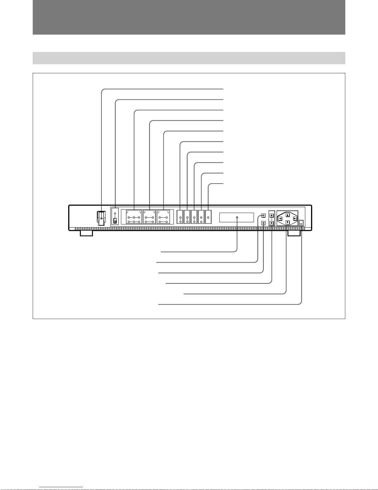
Locations and Functions of Parts and Controls
Front Panel
(Continued)
1 POWER switch
2 PANEL INH indicator and switch
3 OPTION indicators
4 SOURCE SEL indicators
5 ANALOG AUDIO indicators
6 VIDEO STD indicators
8 FEC RATE indicators
7 FREQ BW indicators
9 RF CONDITION indicators
!º ALARM indicator
!¡ Display window
!™ MENU button
!£ ENTER button
!¢ ITEM Â/µ buttons
!∞ Cursor (4/$/“/”) buttons
!§ RESET button
1 POWER switch
Turns the power on and off.
2 PANEL INH (inhibiting panel buttons) indicator
and switch
Set the PANEL INH switch to ON to deactivate the
MENU, ENTER, ITEM Â/µ, and cursor (4/$/“/”)
buttons.
When the PANEL INH switch is set to ON, the
PANEL INH indicator lights up.
3 OPTION (optional boards) indicators
OUT1 indicators
SDTI: Lights up when the BKSM-R101 SDTI
Output Board is installed in the OUT1 section of
the unit.
SDI: Lights up when the BKSM-R102 SDI Output
Board is installed in the OUT1 section of the
unit.
ANALOG: Lights up when the BKSM-R103 Analog
Output Board is installed in the OUT1 section of
the unit.
OUT2 indicators
SDTI: Lights up when the BKSM-R101 SDTI
Output Board is installed in the OUT2 section of
the unit.
SDI: Lights up when the BKSM-R102 SDI Output
Board is installed in the OUT2 section of the
unit.
ANALOG: Lights up when the BKSM-R103 Analog
Output Board is installed in the OUT2 section of
the unit.

6
Locations and Functions of Parts and Controls
4 SOURCE SEL (source selection) indicators
OUT1 indicators
SOURCE1: Lights up when input signals from the
optional board in the IN1 section of the DSM-T1
are output from the optional board in the OUT1
section of the unit.
SOURCE2: Lights up when input signals from the
optional board in the IN2 section of the DSM-T1
are output from the optional board in the OUT1
section of the unit.
To select the input signal source from the optional
board in the OUT1 section, select “01: OUT1 SRC
SEL” in the menu.
For more information, see “Menu Setup” (page 10).
OUT2 indicators
SOURCE1: Lights up when input signals from the
optional board in the IN1 section of the DSM-T1
are output from the optional board in the OUT2
section of the unit.
SOURCE2: Lights up when input signals from the
optional board in the IN2 section of the DSM-T1
are output from the optional board in the OUT2
section of the unit.
To select the input signal source from the optional
board in the OUT2 section, select “02: OUT2 SRC
SEL” in the menu.
For more information, see “Menu Setup” (page 10).
5 ANALOG AUDIO indicators
OUT1 indicators
CH 1/2 or CH 3/4 (or both) indicator(s) lights up when
the BKSM-R103 Analog Output Board is installed in
the OUT1 section of the unit, and when audio signals
are output from the BKSM-R103.
To select the input signal source from the optional
board in the OUT1 section, select “41: OUT1
AUDIO CH” in the menu.
OUT2 indicators
CH 1/2 or CH 3/4 (or both) indicator(s) lights up when
the BKSM-R103 Analog Output Board is installed in
the OUT2 section of the unit, and when audio signals
are output from the BKSM-R103.
To select the input signal source from the optional
board in the OUT2 section, select “51: OUT2
AUDIO CH” in the menu.
6 VIDEO STD (video standard) indicators
525: Lights up when the unit is set up in the 525
standard.
625: Lights up when the unit is set up in the 625
standard.
To select the broadcasting standard, select “03:
VIDEO STD” in the menu.
For more information, see “Menu Setup” (page 10).
7 FREQ BW (frequency bandwidth) indicators
36M: Lights up when the frequency bandwidth is
36 MHz.
18M: Lights up when the frequency bandwidth is
18 MHz.
To select the frequency bandwidth, select “11: FREQ
BW” in the menu.
For more information, see “Menu Setup” (page 10).
8 FEC RATE (Forward Error Correction rate)
indicators
7/8: Lights up when the FEC rate is 7/8.
3/4: Lights up when the FEC rate is 3/4.
To select the FEC rate, select “12: FEC RATE” in the
menu.
For more information, see “Menu Setup” (page 10).
9 RF CONDITION indicators
Indicate the siginal receiving conditions.
Green: Indicates that the siginal receiving conditions
are good.
Yellow: Indicates that picture or sound noise may
appear.
If the condictions are even worse, a warning message
appears in the display window.
For more information about warning messages, see
“Operation Warnings” (page 15).
!º ALARM indicator
When a fault is detected while the unit is in operation,
the ALARM indicator lights up. In this case, a
warning message (0X WARNING) appears in the
display window. The ALARM indicator turns off
when the operation returns to normal.
For more information about warning messages, see
“Operation Warnings” (page 15).
 Loading...