

Page 1

DFS-700/700P
3-203-834-12(1)
DME Switcher
Operating Instructions
Before operating the unit, please read this manual
thoroughly and retain it for future reference.
DFS-700/700P
2000 Sony Corporation
Page 2

Owner’s Record
The model and serial numbers are located in the rear.
Record these numbers in the spaces provided below. Refer
to them whenever you call upon your Sony dealer regarding
this product.
Model No.
WARNING
To prevent fire or shock hazard, do not
expose the unit to rain or moisture.
Serial No.
For customers in the USA (DFS-700 only)
This equipment has been tested and found to comply with
the limits for a Class A digital device, pursuant to Part 15 of
the FCC Rules. These limits are designed to provide
reasonable protection against harmful interference when the
equipment is operated in a commercial environment. This
equipment generates, uses, and can radiate radio frequency
energy and, if not installed and used in accordance with the
instruction manual, may cause harmful interference to radio
communications. Operation of this equipment in a residential
area is likely to cause harmful interference in which case the
user will be required to correct the interference at his own
expense.
You are cautioned that any changes or modifications not
expressly approved in this manual could void your authority
to operate this equipment.
The shielded interface cable recommended in this manual
must be used with this equipment in order to comply with the
limits for a digital device pursuant to Subpart B of Part 15 of
FCC Rules.
Caution
Television prograrms, films, video tapes and other materials
may be copyrighted.
Unauthorized recording of such material may be contrary to
the provisions of the copyright laws.
For the customers in Europe (DFS-700P only)
This product with the CE marking complies with both the
EMC Directive (89/336/EEC) and the Low Voltage Directive
(73/23/EEC) issued by the Commission of the European
Community.
Compliance with these directives implies conformity to the
following European standards:
• EN60950: Product Safety
• EN55103-1: Electromagnetic Interference (Emission)
• EN55103-2: Electromagnetic Susceptibility (Immunity)
This product is intended for use in the following
Electromagnetic Environment(s):
E1 (residential), E2 (commercial and light industrial), E3
(urban outdoors) and E4 (controlled EMC environment, ex.
TV studio).
2
Page 3

Table of Contents
Chapter 1
Overview
Chapter 2
Location and
Function of Parts
and Controls
Chapter 3
Basic Operation
Features of This System ................................................1-1
Option Boards ................................................................1-3
Control Panel................................................................. 2-1
Processor Unit..............................................................2-13
Front Panel ..................................................................... 2-13
Rear Panel ...................................................................... 2-13
DME Switcher Introduction .......................................... 3-1
Sequence of Operations.................................................... 3-1
Example Operation (1): Wipe........................................... 3-2
Example Operation (2): Picture-in-Picture ...................... 3-5
Demonstration .................................................................. 3-8
Using the Menus............................................................. 3-10
Selecting Images......................................................... 3-12
Background Image and Foreground Image.................... 3-12
Selecting Signals Output to the Auxiliary Bus............... 3-16
Selecting an Effect .......................................................3-17
Types of Effect ............................................................... 3-17
Example Effects ............................................................. 3-18
Selection in Direct Pattern Selection Mode ................... 3-23
Selection in Pattern Number Specification Mode .......... 3-24
Modifying the Boundary — Border, Soft Edge,
Beveled Edge, and Crop.....................................3-26
Changing the Pattern Position and Size —
Location (X)(Y)(Z)................................................3-29
Modifying the Pattern — User Modifiable Effects .....3-31
(Continued)
Table of Contents 3
Page 4

Table of Contents
Chapter 3
Basic Operation
(Continued)
Chapter 4
Inserting Characters and Graphics (1) — Title Key...3-33
Luminance Key .............................................................. 3-33
Chroma Keying .............................................................. 3-36
Masking Part of a Title Key............................................ 3-44
Inserting Characters and Graphics (2) —
Downstream Key................................................ 3-45
Setting Up a Transition ................................................3-51
Setting the Transition Time ............................................ 3-51
Setting the Transition Direction ..................................... 3-52
Executing an Effect......................................................3-54
Adjusting Color Mattes................................................3-57
Adjusting Image Colors — Color Correction.............3-59
Freezing an Input Image — Frame Memory
Function...............................................................3-61
Fade-to-Black................................................................3-63
Advanced
Operations
Changing Direct Pattern Assignments........................ 4-1
User Program Effects ................................................... 4-3
Constructing a User Program Effect ................................ 4-3
Types of User Program Effect .......................................... 4-4
Modification Parameters .................................................. 4-5
Creating New User Program Effects .............................. 4-10
Editing User Program Effects......................................... 4-12
Executing User Program Effects .................................... 4-18
Deleting All User Program Effects................................. 4-19
Snapshots.....................................................................4-20
Saving a Snapshot .......................................................... 4-21
Recalling a Snapshot ...................................................... 4-22
Snapshot Demonstration ................................................ 4-23
Reinitializing the Snapshots ........................................... 4-24
4 Table of Contents
Page 5

Chapter 5
Control From
Editing Control
Units
Control From the PVE-500............................................ 5-1
Preparations ...................................................................... 5-2
Cut Editing ....................................................................... 5-2
A/B Roll Editing............................................................... 5-3
Control From the BVE-600............................................ 5-5
Preparations ...................................................................... 5-5
A/B Roll Editing............................................................... 5-6
Control From the BVE-900/2000 Series........................5-8
Preparations ...................................................................... 5-9
Notes on Operation......................................................... 5-10
Control Using GPI Signals ......................................... 5-11
Preparations .................................................................... 5-11
A/B Roll Editing............................................................. 5-12
Turning a Downstream Key On and Off ........................ 5-13
Preread Editing.............................................................5-14
Chapter 6
System
Connections
and Settings
Basic System Connections .......................................... 6-2
Key Signal Connections ................................................6-3
System Connections for Preread Editing ................... 6-4
Connections for an A/B Roll Editing System ..............6-5
Setup Menu Settings......................................................6-7
Setup Menu Organization................................................. 6-7
System Setup (page 1/8)................................................... 6-7
System Information Display (page 2/8) ........................... 6-8
Input Video Setup (page 3/8)............................................ 6-8
Output Video Setup (page 4/8) ......................................... 6-9
Control Panel Setup (page 5/8) ...................................... 6-10
Initializing User Settings (page 6/8)............................... 6-10
Loading User Settings From Memory (page 7/8) .......... 6-10
Saving User Settings in Memory (page 8/8) .................. 6-10
Table of Contents 5
Page 6

Table of Contents
Appendixes
Warning Messages........................................................ A-1
Effect T ype List .............................................................. A-3
Effect Control Parameter List....................................... A-5
Effect Motion Types..................................................... A-21
Effect Pattern Variant Forms and Decorations ......... A-22
Effect Pattern Image List ............................................ A-29
To Exchange the Button Labels.................................A-63
Specifications..............................................................A-64
Glossary.......................................................................A-66
Index.................................................................................I-1
6 Table of Contents
Page 7

Overview
Features of This System
Chapter 1
The Sony DFS-700/700P DME Switcher is a Digital
Multi Effects system, offering high-performance
effects at high image quality. The system consists of a
processor unit and control panel.
Support for fully digital component
systems with SDI inputs and outputs
This system provides SDI interfaces as standard
equipment. This allows it to be incorporated in fully
digital linear editing systems using DVCAM-series,
Betacam SX-series, and other digital VCRs.
Advanced special effects
This system is equipped with advanced special effects,
including trail, lighting effects, ripple, swirl, and
explosion.
Installing the optional BKDF-711 board adds a second
DME channel, and the optional BKDF-712 board
enables 3D mapping effects to be used.
Support for wide range of input/output
signal formats
•There are eight inputs as standard (VIDEO INPUT 1
to 8).
VIDEO INPUT 1 to 4: SDI (serial digital interface)
signals
VIDEO INPUT 5 to 8: analog component signals.
VIDEO INPUT 8 can also be used as an analog
RGB signal input.
Installing the optional BKDF-701 board allows all
eight inputs to be used as either SDI or analog
component inputs.
Installing the optional BKDF-702/702P board allows
four inputs to be used as either Y/C (S-video) or
analog composite inputs.
For details of option boards, see page 1-3.
•The standard outputs are two each of SDI, analog
component, analog composite, and Y/C, for a total of
eight outputs.
For details of option boards, see page 1-3.
Comprehensive title key functions
Luminance keys, chroma keys, and downstream keys
are all provided as standard functions.
Chapter 1 Overview 1-1
Page 8

Features of This System
Color correction function
A YUV color correction function is provided for white
balance adjustment and general color adjustment.
Chapter 1 Overview
User program effect and snapshot
function
•User program effects: This system has a large
number of built-in effects, but also allows the user to
create original effects, and save them in memory, for
execution in the same way as the built-in effects. Up
to twenty user program effect patterns, both linear
and nonlinear, can be saved.
•Snapshot function: The processor unit includes
snapshot registers 0 to 99, each of which can hold a
snapshot of the control panel settings. These can then
be recalled as required.
Aspect ratio selection
In the setup menu it is possible to select either 4:3 or
16:9 as the screen aspect ratio.
Easy operation for live broadcasting
Interfacing with editors
This system is equipped with I/O interfaces for two
sets of control signals, allowing operation together
with various editing control units.
•Nine-pin interface connector (one input/output):
for A/B roll editing (two players, one recorder)
together with a PVE-500, BVE-2000 series, or other
editing control unit
•GPI (General Purpose Interface) and trigger
signal connectors (two inputs): for control from
external equipment not fitted with the 9-pin interface
This system also supports the background through
mode. If connected to a recorder VCR with a preread
function, A/B roll editing with a minimum of two
VCRs is possible. (In background through mode, the
delay to the signal selected on the background bus of
this system is 4H. Note that there are restrictions on
the effect patterns that can be used for preread editing.)
External synchronizing connectors for
higher editing precision
The system is provided with black burst outputs for
synchronizing other connected devices, and a genlock
input for synchronization to an external signal. This
allows more precise editing.
The following features make this system suitable for
live broadcasting from CATV studios and so on.
•Fully-equipped control panel offers easy operability
for signal selection and transition setting.
•Parallel tally output and preview output supplied as
standard
Rack mounting
The processor unit can be mounted in an EIA standard
19-inch rack.
1-2 Chapter 1 Overview
Page 9

Option Boards
The DFS-700/700P system has the following option
boards.
BKDF-701 SDI and Component Input
Board
When this board is installed, it allows all eight video
inputs to be used as either SDI or analog component
inputs. When using this board, you can select the types
of the optional inputs individually, using the setup
menu.
BKDF-702/702P Y/C and Composite Input
Board
When this board is installed, it allows four video
inputs to be used as either Y/C (S-video) or analog
composite inputs. When using this board, you can
select the types of the optional inputs individually,
using the setup menu.
BKDF-711 2nd Channel DME Board
This board provides a second DME channel, enabling
two-picture box, two-picture brick, and other effects.
Chapter 1 Overview
BKDF-712 3D Video Mapping Effects
Board
This board provides 3D mapping effects, including 3D
page turn, 3D beveled edge, and other effects.
Chapter 1 Overview 1-3
Page 10

Page 11
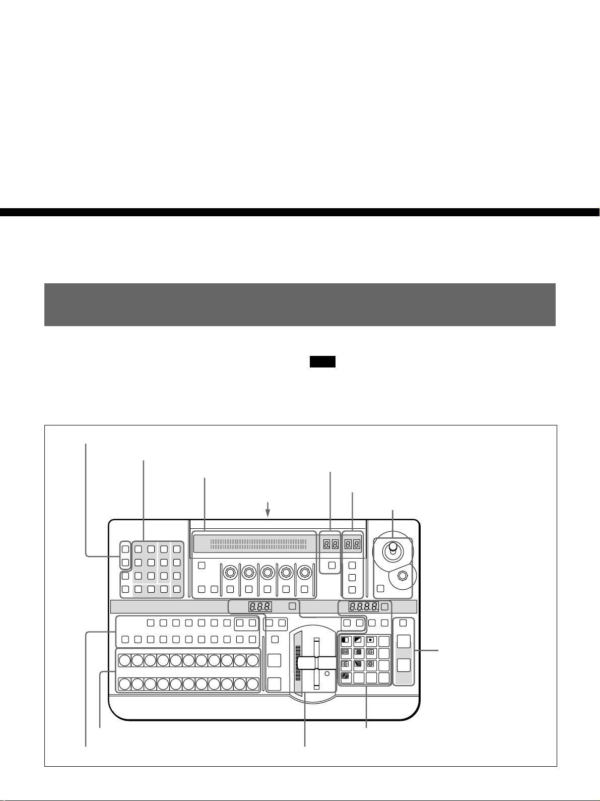
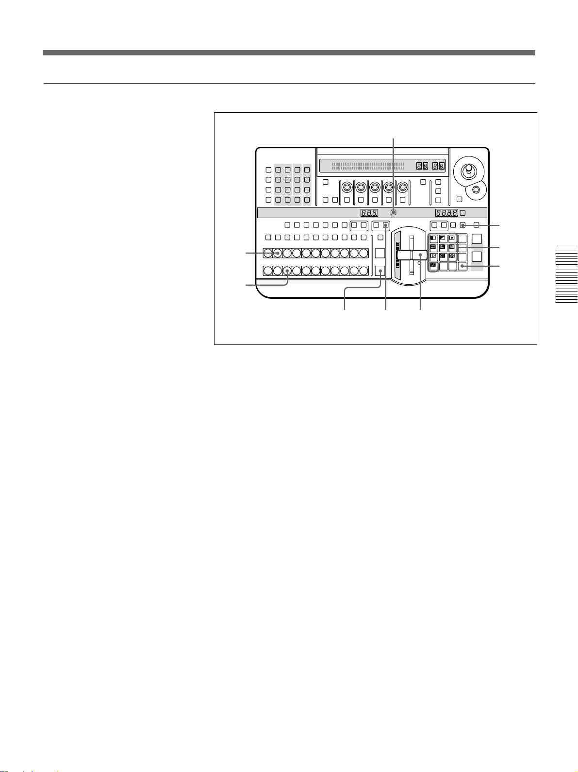
Control Panel
Chapter 2
Location and Function
of Parts and Controls
This section describes the control panel, which is
divided into several sections, as shown below. See the
page numbers shown in parenthesis for more details.
6 EDITOR and GPI buttons
7 Menu control section
TITLE
12
EDITOR LUM LUM LUM
GPI CRK CRK BORDER BEVELD
SET UP MASK MASK MASK SOFT
SHIFT CCR LIGHTING BORDERMATTES
CCR TITLE 1
AUXILIARY
BLACK MEMORY INT
12345678
BACKGROUND
BLACK
12345678
FOREGROUND
BLACK
12345678
DSK EDGE
SOURCE
TRAIL
SHADOW
EDGE
TITLE 2
SOURCE
(see page 2-7)
(see page 2-7)
8 Effect control section
(see page 2-10)
INITIAL
PATTERN
PAGE
F1 F2 F3 F4 F5
ADJ
DSK
SUPER BG FRGD 2 MEMORY FRAME FREEZ MIX EFFECT
FILL
TRANS RATE
MEMORY
MEMORY
VIDEO
VIDEO
VIDEO
INT
INT
qs 25-pin
connector
page 2-12)
EFFECT
TITLE
CUT
AUTO
TRANS
Note
If you make an error in operation, a warning sound
may occur. You can switch off this audible warning
(see page 6-10).
9 User program section
q; Snapshot section
(see
USER PGM
SNAP SHOT
STATUS EDIT
LEARNEDIT
RECALL
LOCATION
HOLD
DSK
FTB
SET
PATTERN NUMBER
INPUT
N/R REV DSK PVWDIRECT
RECALL
789
456
123
DOWN UP
0
PATTERN/KEY PAD
SET
DIRECT
PATTERN
LAST X
P IN P
ENTER
INS
DEL
RST
(see page 2-11)
(see page 2-11)
qa Location section
FADE
TO
BLACK
5 Fade-to-black
DSK
and DSK section
(see page 2-6)
(see page 2-12)
2 Primary cross-point bus section
1 Delegation section
(see page 2-2)
(see page 2-3)
4 Pattern/numeric keypad
3 Effect transition section
Chapter 2 Location and Function of Parts and Controls 2-1
(see page 2-5)
(see page 2-4)
Page 12
Control Panel
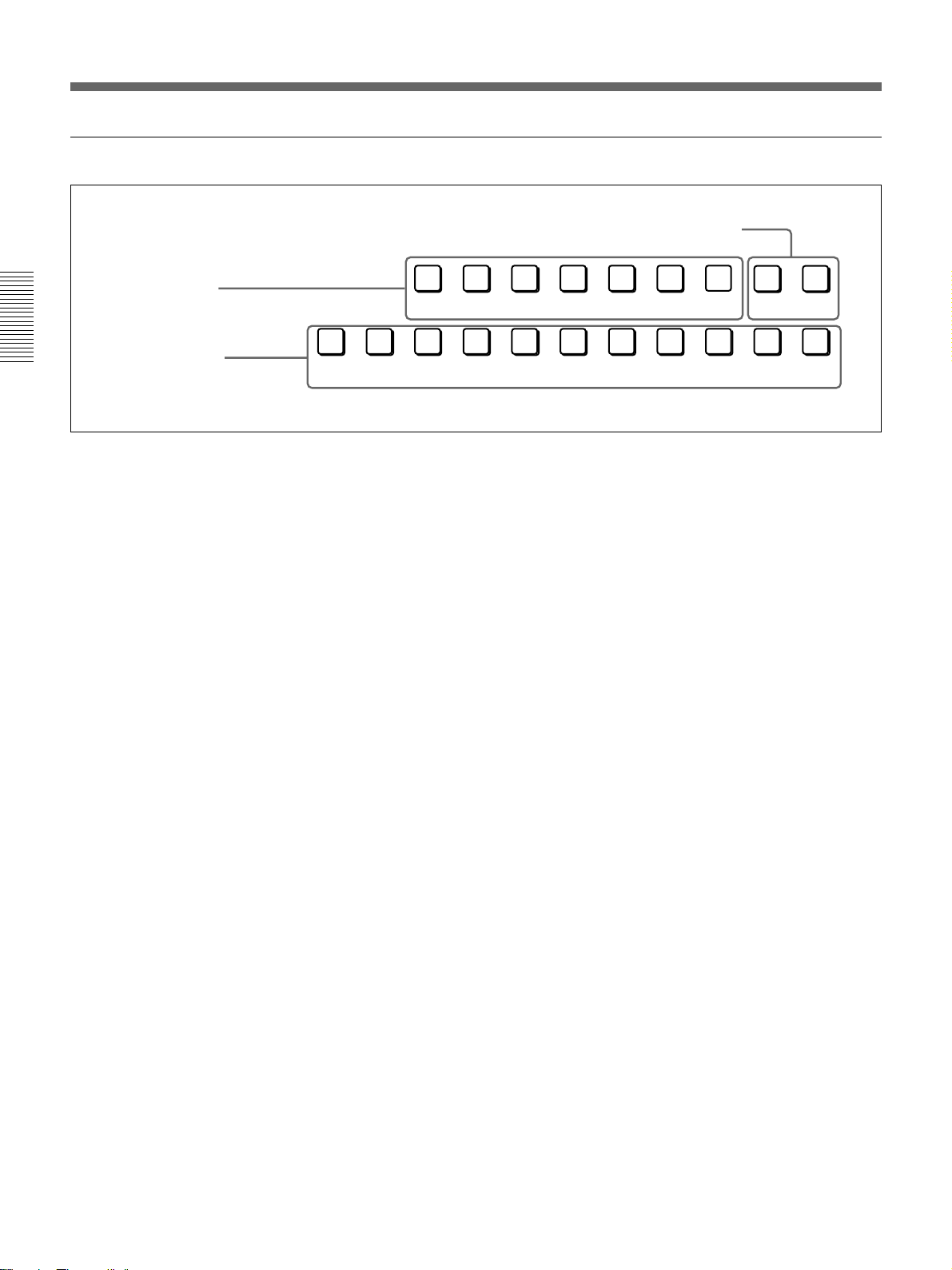
1 Delegation section
3 Frame memory buttons
1 Delegation buttons
2 AUXILIARY buttons
Chapter 2 Location and Function of
Parts and Controls
1 Delegation buttons
Use these buttons to delegate the input signal
corresponding to the selected AUXILIARY button to
the corresponding function. Pressing one of these
buttons lights it, and the corresponding AUXILIARY
button also lights. Any other previously lit delegation
button goes off.
CCR (color corrector) button: Signal for color
correction
TITLE 1 SOURCE button: Title 1 source signal for
inserting characters and graphics using a title key
TITLE 2 SOURCE button: Title 2 source signal for
inserting characters and graphics using a title key
(only available when the optional BKDF-711 2nd
Channel DME Board is installed)
DSK (downstream keyer) FILL button: Fill signal
for the downstream keyer
SUPER BG (background) button: Background
image for 3D effects
FRGD (foreground) 2 button: One of the
foreground images for 3D effects
MEMORY button: Signal captured in frame
memory
CCR TITLE 1
AUXILIARY
BLACK MEMORY INT
12345678
SOURCE
TITLE 2
SOURCE
DSK
SUPER BG FRGD 2 MEMORY FRAME FREEZ
FILL
VIDEO
2 AUXILIARY buttons
Select the input signal to be assigned to the function
selected with a delegation button.
Select from the following buttons.
BLACK button: Black burst signal generated by the
internal synchronizing signal generator in this unit
Buttons 1 to 8: Signals input to the VIDEO INPUT 1
to 8 connectors on the rear panel of the processor
unit. You can set the assignment of buttons to
input connectors in the setup menu.
MEMORY button: Signal recorded in frame
memory
INT (internal) VIDEO button: Signal generated by
the internal video signal generator
3 Frame memory buttons
FREEZ button: To capture the input signal selected
by the MEMORY button in the delegation buttons
(excluding the frame memory output signal) as a
freeze image in frame memory, press this button,
turning it on.
Press once more to end the freeze, turning it off.
FRAME button: Select whether to capture a frame
or a field with the FREEZ button. Press this
button, turning it on, to freeze a frame; when the
button is off a field is captured.
When capturing fields, you can select in the setup
menu whether to capture an odd or an even field.
2-2 Chapter 2 Location and Function of Parts and Controls
Page 13
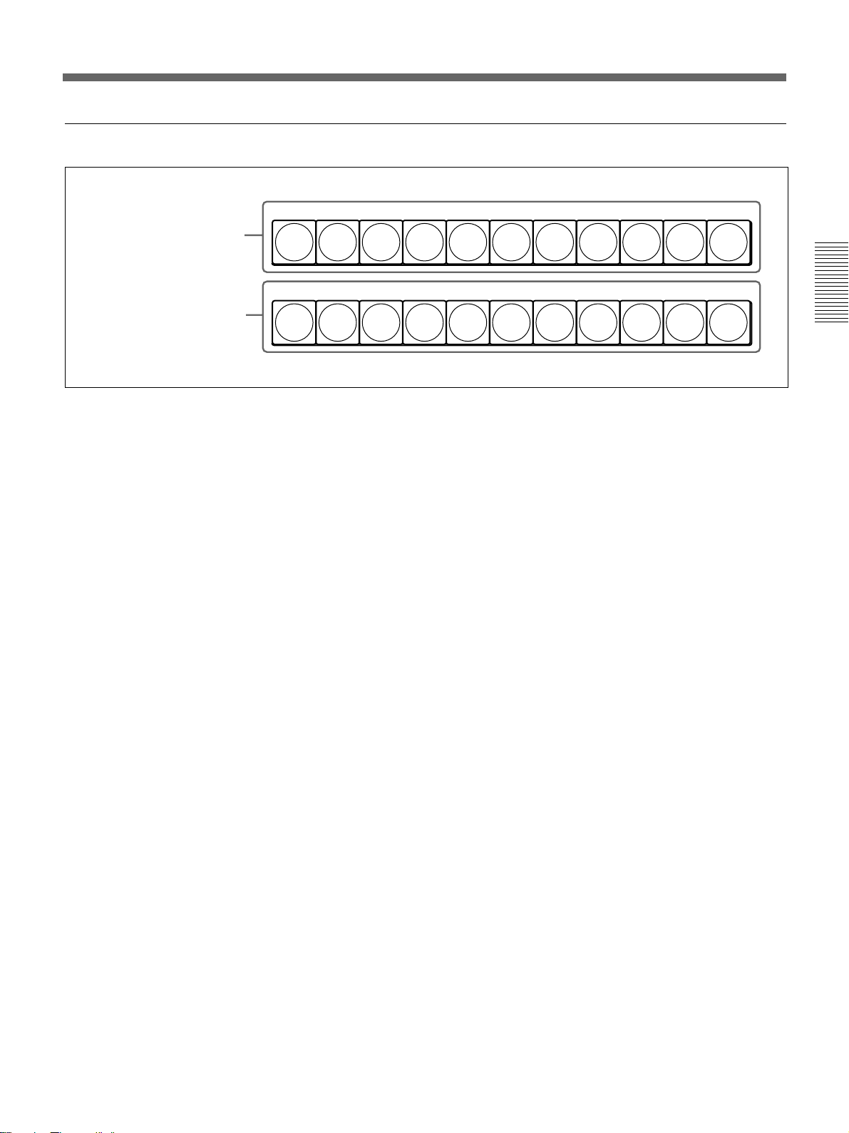
2 Primary cross-point bus section
BACKGROUND
1 BACKGROUND bus buttons
2 FOREGROUND bus buttons
BLACK
FOREGROUND
BLACK
12345678
12345678
MEMORY
MEMORY
INT
VIDEO
INT
VIDEO
Chapter 2 Location and Function of
Parts and Controls
1 BACKGROUND bus buttons
Select the image to form the background for an effect.
Select from the following buttons.
BLACK button: Select the black burst signal
generated by the internal synchronizing signal
generator in this unit.
Buttons 1 to 8: Signals input to the VIDEO INPUT 1
to 8 connectors on the rear panel of the processor
unit. Press a button, turning it on, to select the
corresponding signal.
You can set the assignment of buttons to input
connectors in the setup menu.
MEMORY button: Select the signal recorded in
frame memory.
INT (internal) VIDEO button: Select the internal
video signal selected by pressing the MATTES
button in the menu control section. If you hold
down this button and press the DOWN and UP
buttons in the pattern/numeric keypad, the
selected video signal pattern changes.
When the signal on the background bus is output from
the PGM OUT connector on the rear panel of the
processor unit, the button which has been pressed
lights red.
2 FOREGROUND bus buttons
Select the image to form the foreground for an effect
(or the “new” video in a transition).
The functions of the buttons are the same as in the
BACKGROUND bus buttons.
When the signal on the foreground bus is output from
the PGM OUT connector on the rear panel of the
processor unit, the button which has been pressed
lights red. If the signal is not output, the button pressed
lights amber.
Chapter 2 Location and Function of Parts and Controls 2-3
Page 14
Control Panel
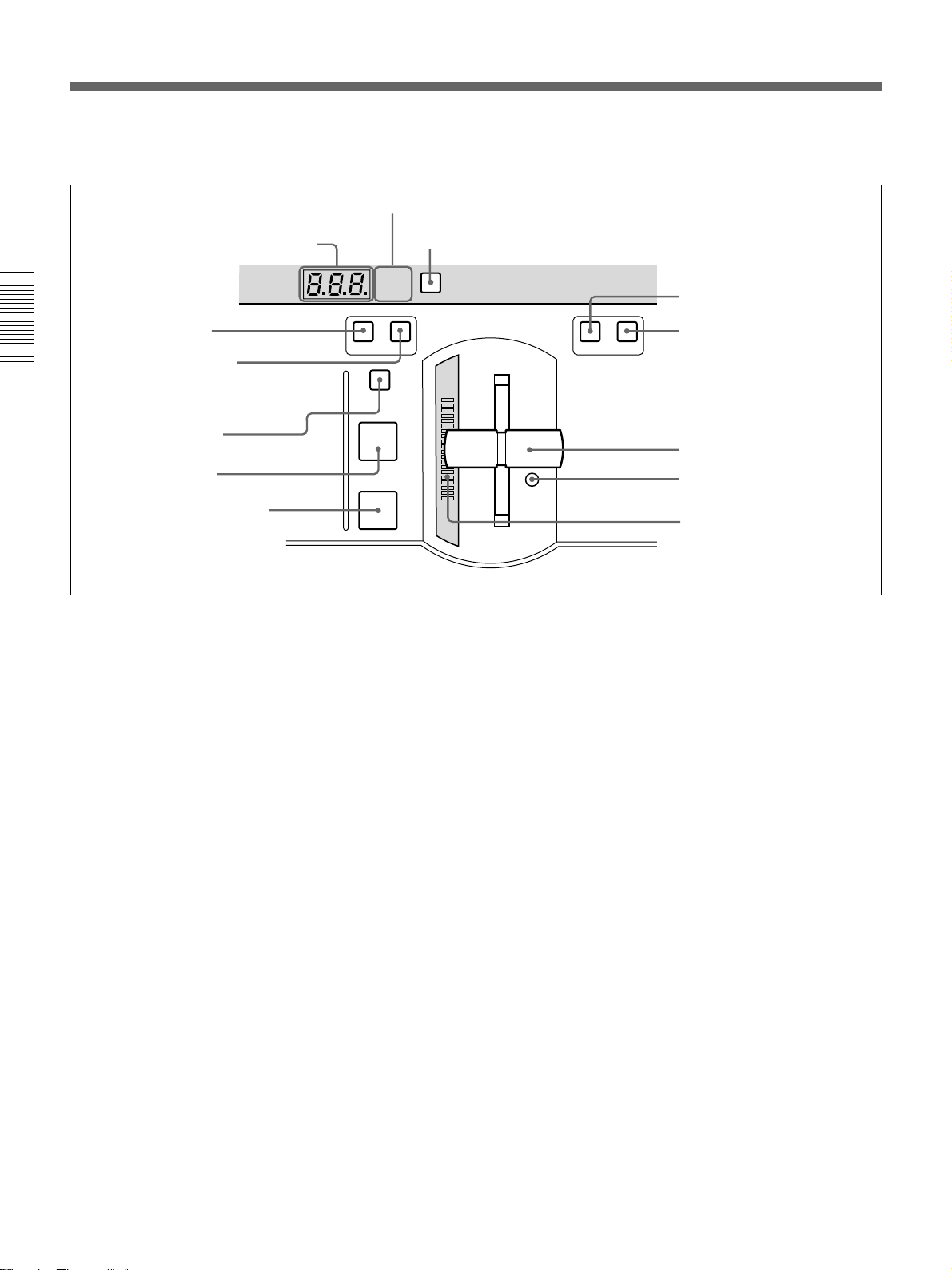
3 Effect transition section
2 Display window mode indicators
1 TRANS RATE display window
4 MIX button
Chapter 2 Location and Function of
Parts and Controls
5 EFFECT button
6 TITLE button
7 CUT button
8 AUTO TRANS button
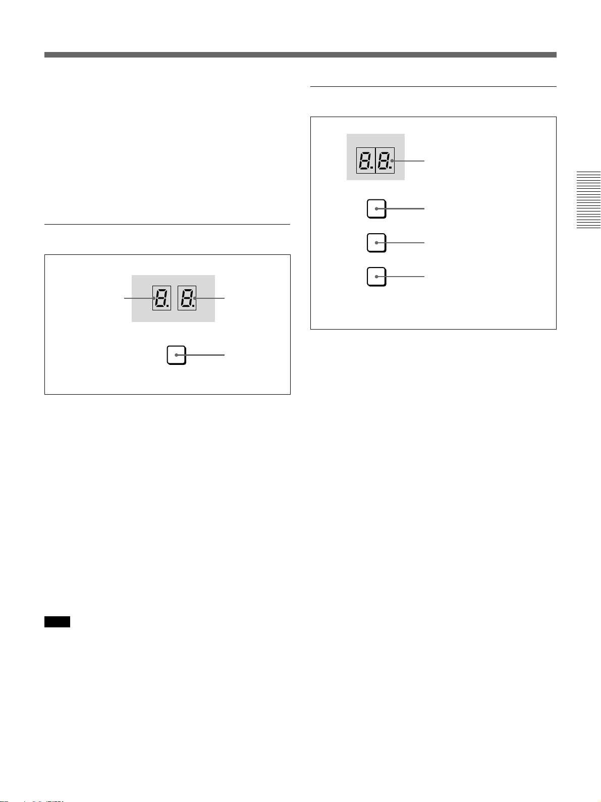
1 TRANS (transition) RATE display window
This shows the transition time for effects, downstream
keys, and fade-to-black, in units of frames. While you
are entering a time, the dot at the lower right of each
numeral lights.
2 Display window mode indicators
These indicate the kind of transition time shown in the
TRANS RATE display window.
EFFECT: Transition time of an effect
DSK: Transition time of a downstream key
FTB: Transition time of a fade-to-black
3 SET button
To set the transition time for an effect, downstream
key, or fade-to-black, press this button, turning it on.
While it is lit, each time you press, the display window
mode indicators change. To set the transition time
corresponding to the display of the display window
mode indicators, enter the value using the pattern/
numeric keypad.
4 MIX button
To carry out the next transition without applying an
effect pattern, but as a mix, press this button, turning it
on.
TRANS RATE
EFFECT
DSK
FTB
MIX EFFECT
TITLE
CUT
AUTO
TRANS
3 SET button
SET
9 N/R button
q; REV button
N/R REV
qa Fader lever
qs Fader lever stiffness
adjusting screw
qd Transition indicator
5 EFFECT button
To carry out the next transition with an effect pattern
applied, press this button, turning it on.
6 TITLE button
To carry out an effect or a mix in title mode, press this
button, turning it on. The title keying is carried out,
inserting the characters and graphics with the effect
pattern and transition settings applied.
7 CUT button
Press this button to carry out an instantaneous
transition.
8 AUTO TRANS (automatic transition) button
Press this button to carry out an effect automatically.
When you press this button, the effect is carried out
automatically, with the transition time which has been
set. During the transition this button is lit. Pressing this
button during the transition pauses it. Press the button
once more to resume the transition.
If you set the fader lever to an intermediate position
and press this button, the transition pauses at the
position corresponding to the fader lever position.
2-4 Chapter 2 Location and Function of Parts and Controls
Page 15
9 N/R (normal/reverse) button
To carry out an effect in normal/reverse (i.e.
alternating) mode, press this button, turning it on. It
lights automatically for animation effects and title
keys.
4 Pattern/numeric keypad
This is used for effect pattern selection, transition time
setting, and other data entry.
q; REV (reverse) button
To carry out an effect in the reverse direction, press
this button, turning it on.
For an effect for which normal/reverse (alternating)
operation is possible, once the effect is carried out, the
direction is automatically reversed. After an effect is
carried out in the normal (i.e. forward) direction, this
button lights. After an effect is carried out in the
reverse direction, this button goes off.
qa Fader lever
Move this to carry out an effect transition manually.
Note
After powering the system on, move the fader lever to
the end of its travel once in each direction. This
ensures that the fader lever will function correctly.
qs Fader lever stiffness adjusting screw
Turn this screw with a miniature Phillips screwdriver
to adjust the fader lever stiffness. Turn clockwise to
make the fader lever harder to move, and
counterclockwise to make it easier to move.
qd Transition indicator
This indicator consisting of 20 LEDs shows the
progress of an effect transition.
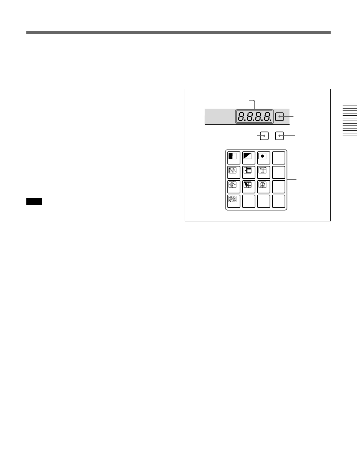
1 PATTERN NUMBER
display window
PATTERN NUMBER
3 DIRECT RECALL button
789
456
123
DOWN UP
0
PATTERN/KEY PAD
DIRECT
RECALL
DIRECT
PATTERN
LAST X
P IN P
ENTER
SET
INS
DEL
RST
2 SET
button
4 DIRECT
PATTERN
button
5 PATTERN/
KEY PAD
buttons
1 PATTERN NUMBER display window
This shows an effect pattern number.
While you are entering a pattern number, the dot at the
lower right of each numeral lights.
2 SET button
Press this button, turning it on, to enter the pattern
number specification mode. In this mode, you can use
the PATTERN/KEY PAD buttons to specify an effect
pattern number.
Press this button once more, turning it off, to return to
the direct pattern selection mode.
Chapter 2 Location and Function of
Parts and Controls
3 DIRECT RECALL button
Press this button, turning it on, to enter the direct recall
mode. In this mode, pressing one of the PATTERN/
KEY PAD buttons 0 to 9 recalls the corresponding
snapshot 0 to 9.
4 DIRECT PATTERN button
Press this button, turning it on, to enter the direct
pattern selection mode. In this mode, you can use the
PATTERN/KEY PAD buttons (0 to 9 and P IN P/
RST) to directly select the assigned effect patterns.
When the system is powered on, and after exiting any
other operating mode, it automatically switches to
direct pattern selection mode.
Chapter 2 Location and Function of Parts and Controls 2-5
Page 16
Control Panel
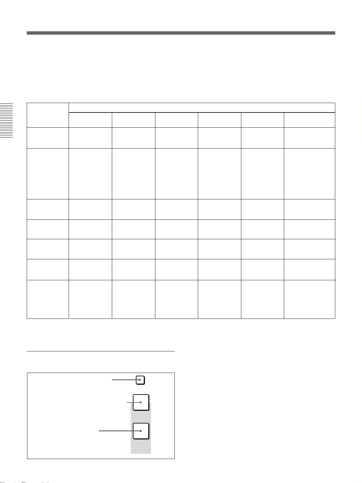
5 PATTERN/KEY PAD buttons
These function as shown in the following table,
according to the selected mode.
Button
DIRECT
PATTERN
0 to 9 Select the
Chapter 2 Location and Function of
LAST X/INS –
Parts and Controls
DEL –
P IN P/RST
UP Increment the
DOWN Decrement the
ENTER – Confirm the
pattern shown
on the button.
a)
Select the
pattern shown
on the button.
pattern number.
pattern number.
a)
Changing labels
You can change the labels on the buttons, using the
supplied labels.
For details of how to change the labels, see page A-63.
Functions of the PATTERN/KEY PAD buttons
Mode
PATTERN
Set the pattern
number.
–
Delete the last
character
entered.
Reset the input
value.
Increment the
pattern number.
Decrement the
pattern number.
input value.
TRANS USER PGM
Set the
transition time.
– Add a key
Delete the last
character
entered.
Reset the input
value.
Increment the
transition time
by one frame.
Decrement the
transition time
by one frame.
Confirm the
input value.
–
frame.
Delete a key
frame.
Initialize the
parameters.
Increment the
key frame
number.
Decrement the
key frame
number.
Change the key
frame.
SNAP SHOT
Specify a
snapshot
number.
Return to the
state before
recalling a
snapshot.
(Press LAST X
while holding
down the
ENTER button.)
Delete the last
character
entered.
Reset the input
value.
Increment the
snapshot
number.
Decrement the
snapshot
number.
Confirm the
input value.
DIRECT RECALL
Recall one of
snapshots 0 to 9.
Return to the state
before recalling a
snapshot. (Press
LAST X while
holding down the
ENTER button.)
–
–
Increment the
snapshot number.
Decrement the
snapshot number.
Return to the state
before recalling a
snapshot. (Press
LAST X while
holding down the
ENTER button.)
–: Not used
a) For the pattern allocation, see pages 3-18 to 3-20.
5 Fade-to-black and DSK section
1 DSK PVW button
DSK PVW
FADE
2 FADE TO BLACK button
3 DSK button
TO
BLACK
DSK
2-6 Chapter 2 Location and Function of Parts and Controls
1 DSK PVW (downstream keyer preview) button
When this button is pressed, turning it on, the program
output video is output from the preview output
connectors with the downstream key inserted.
2 FADE TO BLACK button
Press this button, turning it on, to change the entire
program output video to a preset color (factory default:
black). To set the color, press the MATTES button in
the menu control section, and display the setting menu
in the effect control section ((F1) SELECT-FTB).
By pressing the SET button in the effect transition
section, you can set the fade-to-black transition time.
Page 17
3 DSK (downstream keyer) button
Press this button, turning it on, to insert the
downstream key set by the DSK section buttons in the
menu control section into the program output video.
By pressing the SET button in the effect transition
section, you can set the downstream key transition
time.
6 EDITOR and GPI buttons
1 TITLE section
6 SET UP
button
SET UP MASK MASK MASK SOFT
TITLE
12
LUM LUM LUM
CRK CRK BORDER BEVELD
DSK EDGE
TRAIL
SHADOW
EDGE
2 DSK section
3 EDGE
section
1 EDITOR button
EDITOR
2 GPI button
GPI
1 EDITOR button
Press this button, turning it on, to accept control from
an external editor connected to the EDITOR connector
on the rear panel of the processor unit.
Press this button once again to turn it off; control is no
longer accepted from the external editor.
2 GPI button
Press this button, turning it on, to accept GPI signals
input to the GPI/T 1 and 2 connectors on the rear panel
of the processor unit.
Press this button once again to turn it off; GPI signals
are no longer accepted.
7 Menu control section
For various effect settings, you press a particular
button in the menu control section, to display a setting
menu in the effect control section. Some buttons toggle
on and off when pressed: in this case the
corresponding effect is disabled when the button is off.
Displaying the menu for a button already lit
Hold down the SHIFT button and press the button
again. This leaves the button lit (and the effect
enabled), while bringing up the menu in the effect
control section. For the LUM and CRK buttons in the
TITLE section, it is not necessary to hold down the
SHIFT button.
5 SHIFT
button
SHIFT CCR LIGHTING BORDERMATTES
4 CCR, LIGHTING, and
MATTES buttons
1 TITLE section
The title key function allows you to superimpose
characters or graphics by cutting out part of the
foreground video with a key source signal, and
applying the effect to the background video.
There are two ways of using the key source signal: as a
luminance key depending only on image intensity, or
as a chroma key, based on a particular color.
Using the buttons in columns 1 and 2 of the TITLE
section, you can insert two title keys (TITLE 2
requires the optional BKDF-711 board to be installed).
To insert a title key, press the TITLE button in the
effect transition section.
The TITLE 1 and TITLE 2 buttons include the
following.
CRK (chroma key) button: Press this to use a
chroma key to cut out the image. When pressed,
this button lights, and portions of the foreground
image of the designated color are cut out as the
key source signal. When this button is lit, the
LUM button is off.
You can carry out chroma keying simply, using
the auto chroma key function.
LUM (luminance) button: Press this to use a
luminance key to cut out the image. When
pressed, this button lights, and portions of the
foreground image are cut out based on the
luminance level. When this button is lit, the CRK
button is off.
Chapter 2 Location and Function of
Parts and Controls
Chapter 2 Location and Function of Parts and Controls 2-7
Page 18

Control Panel
MASK button: Press this button to mask off a part
of the key source signal. When you press this
button, it lights, and the system is now in mask
mode, and you can select a rectangular mask in
the effect control section. Normally, the area
outside the mask rectangle is the area which is
masked. To invert the mask, so that the area inside
the rectangle is masked, set INVERT (F5) to ON
in the effect control section.
Press the button once more to turn it off and end
mask mode.
Chapter 2 Location and Function of
2 DSK (downstream keyer) section
Using a downstream key, you can add characters or
Parts and Controls
graphics to an image to which an effect has already
been applied. Unlike a title key, you can add this to an
image with a foreground and background
superimposed. To insert a downstream key, press the
DSK button in the fade-to-black and DSK section.
LUM (luminance) button: Press this to display a
menu in the effect control section for adding a key
based on the luminance level of an input signal. In
the effect control section you can select the input
signal to the DSK KEY IN connector on the rear
panel or the input signal selected by the DSK
FILL button in the delegation section as the key
source signal.
BORDER button: Press this button to apply a border
to the characters and graphics inserted as a
downstream key. When you press this button, it
lights, and you can adjust the border settings in the
effect control section.
Press the button once more to turn it off, and
remove the border.
MASK button: Press this button to mask unwanted
parts of the characters and graphics inserted as a
downstream key. When you press this button, it
lights, and the system is now in mask mode, and
you can select a rectangular mask in the effect
control section. Normally, the area outside the
mask rectangle is the area which is masked. To
invert the mask, so that the area inside the
rectangle is masked, set INVERT (F5) to ON in
the effect control section.
Press the button once more to turn it off and end
mask mode.
3 EDGE section
This controls the edge effects applied to the boundary
between the foreground and background images.
TRAIL SHADOW button: Press this button to
apply a trail, drop border, or shadow effect. When
you press this button, it lights, and you can select
and adjust the effect in the effect control section.
•Trail: The foreground pattern leaves a trail of
afterimages.
•Drop border: This applies a border in the
background of the foreground image.
•Shadow: This applies a shadow behind the
foreground image.
Press the button once more to turn it off and
remove the edge effect.
BEVELD (beveled) EDGE button: Press this button
to apply a three-dimensional beveled effect to the
boundary between the foreground and background
images. When you press this button, it lights, and
you can adjust the beveled edge settings in the
effect control section.
Press the button once more to turn it off and
remove the beveled edge effect.
SOFT button: Press this button to soften the
boundary between the foreground and background
images. When you press this button, it lights, and
you can adjust the degree of softness in the effect
control section.
Press the button once more to turn it off and
remove the soft edge effect.
BORDER button: Press this button to apply a border
to the boundary between the foreground and
background images. When you press this button, it
lights, and you can adjust the border settings in the
effect control section.
Press the button once more to turn it off and
remove the border.
Adjusting the cropping: To adjust the cropping, use
the second page (CROP) of the adjustment menu
for beveled edge, soft edge, or border.
2-8 Chapter 2 Location and Function of Parts and Controls
Page 19

4 CCR, LIGHTING, and MATTES buttons
CCR (color corrector) button: Press this button to
use the color corrector. When you press this
button, it lights, and you can adjust the color
corrector settings in the effect control section.
Press the button once more to turn it off and exit
the color corrector.
LIGHTING button: Press this button to apply
lighting effects to the foreground image. When
you press this button, it lights, and you can adjust
the lighting settings in the effect control section.
Press the button once more to turn it off and
remove the lighting effect.
MATTES button: By pressing this button, you can
carry out various matte adjustments, matte copies,
and internal video signal selections in the effect
control section.
5 SHIFT button
When a button in the menu control section is lit, but
the corresponding menu is not displayed in the effect
control section, hold down the SHIFT button and press
the lit button. This brings up the menu, without
interrupting the function selection, and leaving the
button lit.
This applies to the following buttons:
•MASK buttons in the TITLE section
•BORDER and MASK buttons in the DSK section
•TRAIL SHADOW, BEVELD EDGE, SOFT, and
BORDER buttons in the EDGE section
•CCR button and LIGHTING button
6 SET UP button
To access the setup menus for system and control
panel settings, press this button. The setup menu
appears in the effect control section.
Chapter 2 Location and Function of
Parts and Controls
Chapter 2 Location and Function of Parts and Controls 2-9
Page 20
Control Panel
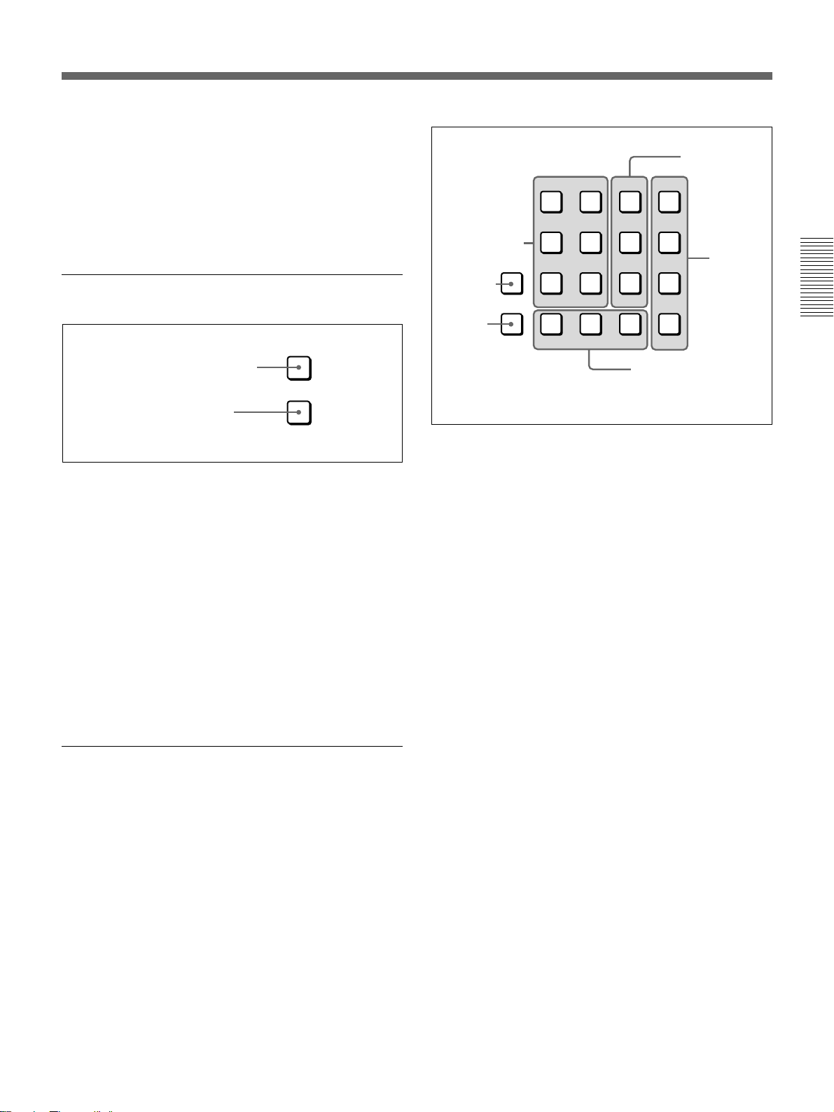
8 Effect control section
1 Menu display
Chapter 2 Location and Function of
2 INITIAL button
Parts and Controls
3 PAGE button
4 PATTERN ADJ button
INITIAL
PATTERN
ADJ
PAGE
F1 F2 F3 F4 F5
5 Control knobs
1 Menu display
This shows system and effect settings. Watch this
display while checking and adjusting the settings.
Menu name or pattern number
Settings
INIT SETUP--SNAP--USRPGM--KEYPAD EXEC
6/8 OFF OFF OFF OFF
Setting values (ON/OFF or parameter values)
Menu page
2 INITIAL button
This returns settings to their factory defaults.
•To return a selected setting to its factory default
Hold down the INITIAL button, and press the
corresponding F button (F1 to F5).
•To return all settings on the selected page to their
factory defaults
Hold down the INITIAL button, and press the PAGE
button.
•To return all settings on all pages of the currently
selected menu to their factory defaults (not valid
in setup menu or matte menu)
Hold down the INITIAL button, and press the
PATTERN ADJ button.
6 F1 to F5 buttons
3 PAGE button
Press this button to move to the next page of a menu.
Pressing this button on the last page of a menu returns
to the first page.
Holding down the SHIFT button in the menu control
section and pressing this button moves to the previous
menu.
4 PATTERN ADJ (adjust) button
Press this button to adjust the settings for the pattern
number displayed in the PATTERN NUMBER display
window.
This displays the settings for the pattern in the effect
control section.
5 Control knobs
These correspond to the five settings shown in the
menu display. Turn the corresponding knob to adjust a
setting.
6 F1 to F5 buttons
These correspond to the five settings shown in the
menu display.
Press the corresponding button to select a setting, or
toggle it on and off.
2-10 Chapter 2 Location and Function of Parts and Controls
Page 21
•Changing a setting value preceded by “+” (setup
menu operations)
Hold down the corresponding F button (F1 to F5),
and turn the control knob.
•Changing a setting value followed by “+” (user
program effect setting operations)
Hold down the corresponding F button (F1 to F5),
and enter the numeric value using the numeric
keypad.
9 User program section
USER
PGM
1 STATUS display
STATUS
EDIT
2 EDIT display
q; Snapshot section
SNAP SHOT
LEARN
RECALL
HOLD
INPUT
1 SNAP SHOT number display
2 LEARN button
3 RECALL button
4 HOLD INPUT button
Chapter 2 Location and Function of
Parts and Controls
3 EDIT button
EDIT
1 STATUS display
When a user program effect is selected, this shows the
number of key frames comprising the effect.
(Maximum 8)
2 EDIT display
In the user program edit mode, this shows the key
frame number to which editing applies.
3 EDIT button
Press this button to edit a user program effect. When
you press this button, it lights, and the system enters
the user program edit mode.
Press the button once more to turn it off and exit the
user program edit mode.
Note
If you press the EDIT button when an effect other than
a user program effect is selected, this does not switch
to user program edit mode.
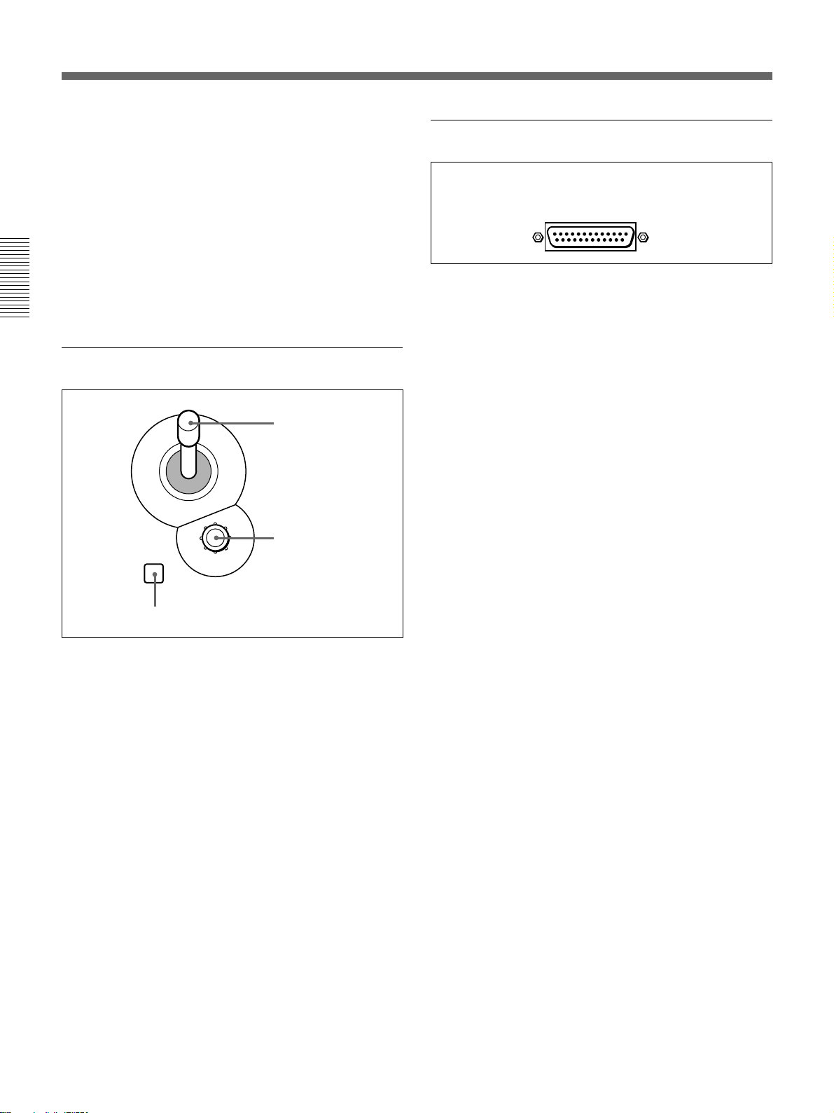
1 SNAP SHOT number display
This shows a snapshot number (0 to 99). While you are
entering a number, the dot at the lower right of each
numeral lights.
2 LEARN button
Press this button to save the control panel settings as a
snapshot (learn function).
When you press this button, it lights, and the system
enters learn mode. Enter the snapshot number (0 to 99)
from the numeric keypad, and press the ENTER button
to save the control panel settings in the snapshot.
3 RECALL button
Press this button to recall settings saved as a snapshot.
When you press this button, it lights, and the system
enters recall mode. Enter the snapshot number (0 to
99) from the numeric keypad, and press the ENTER
button to recreate the control panel settings from the
snapshot on the control panel.
Chapter 2 Location and Function of Parts and Controls 2-11
Page 22
Control Panel
4 HOLD INPUT button
To hold the primary cross-point bus settings and the
auxiliary bus settings (signal selections) fixed when
recalling a snapshot, press this button. When you press
this button, it lights, and when you recall a snapshot,
the system is in the hold input mode. When you recall
a snapshot in this mode, all settings are recreated on
the control panel except those relating to the primary
cross-point bus and the auxiliary bus.
Press the button once more to turn it off and exit the
hold input mode.
Chapter 2 Location and Function of
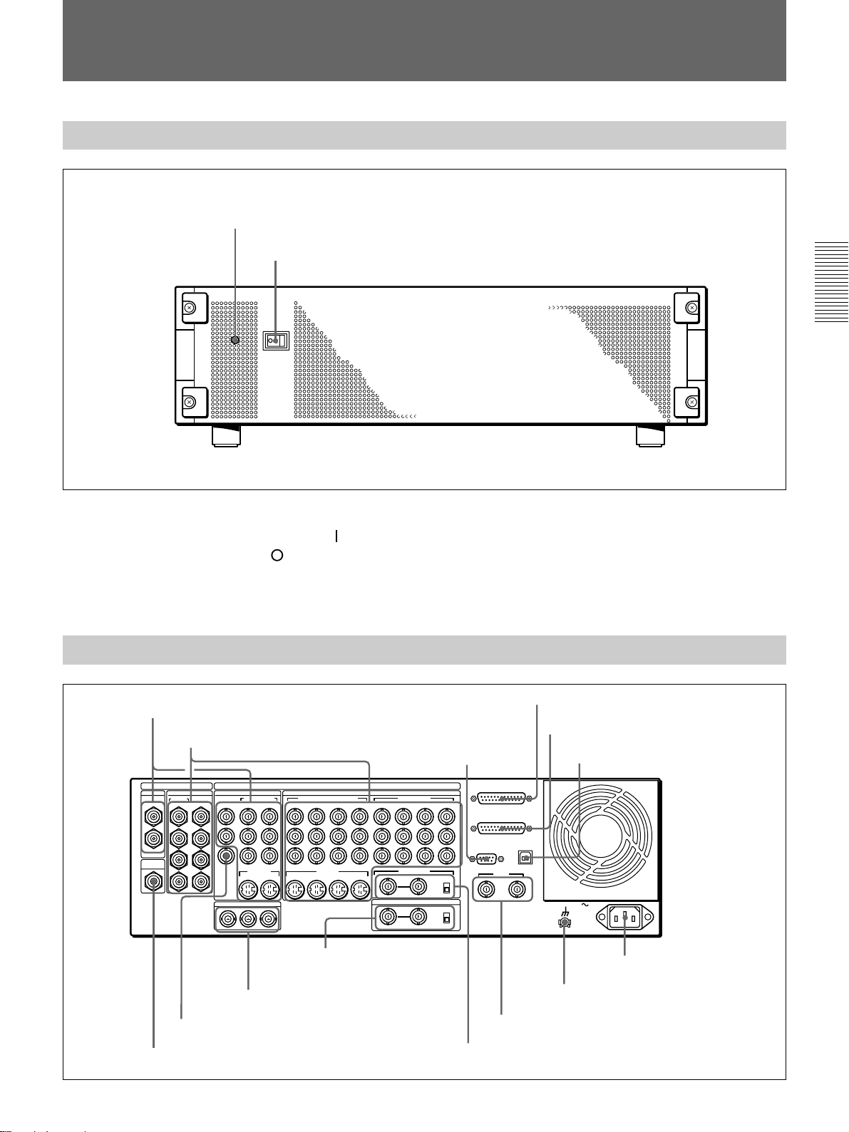
qa Location section
Parts and Controls
qs 25-pin connector (rear panel)
Use the supplied 25-pin control cable to connect this to
the PANEL connector on the processor unit.
2 Joystick
3 Z-knob
LOCATION
1 LOCATION button
1 LOCATION button
Press this button to use the joystick and Z-knob. When
you press this button, it lights, and enables the joystick
and Z-knob.
Press the button once more to disable the joystick and
Z-knob, and return the effect pattern to its default
position.
Holding down the INITIAL button while pressing this
button returns the setting to its default value.
2 Joystick
Use the joystick to position the effect pattern in the xand y-directions.
3 Z-knob
Turn the Z-knob to move an effect pattern in the depth
direction (the z-axis). With this you can change the
effective size of the pattern.
2-12 Chapter 2 Location and Function of Parts and Controls
Page 23
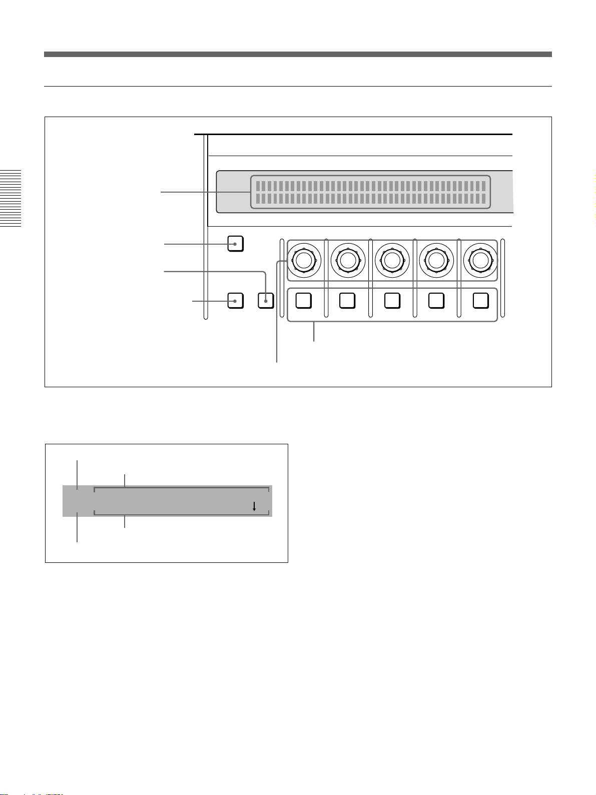
Processor Unit
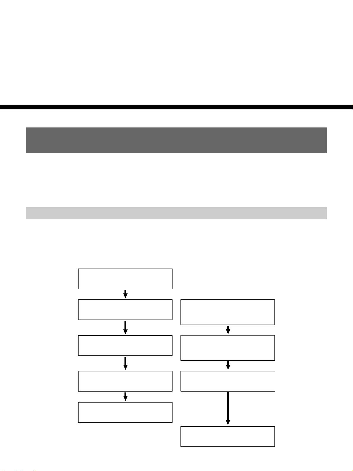
Front Panel
Power indicator
Power switch
Chapter 2 Location and Function of
Parts and Controls
Power switch and indicator
This powers the unit on and off. Press the “
the switch to power on, and the “
” side to power off.
” side of
When the power is on, the power indicator lights
amber.
Rear Panel
1 PGM OUT connectors
2 VIDEO INPUT connectors
PGM OUT
1
2
CLEAN
OUT
DIGITAL I/O
OPTION
5
6
7
8
SDI INPUT PGM OUT
1
2
3
4
COMPOSITE
1
2
PVW
BLACK BURST OUT
3
COMPONENT
21
2 1
S VIDEO
2
Y
R-Y
B-Y
1
ANALOG I/O
(OPTION)
65
S VIDEO
(OPTION)
VIDEO INPUT
COMPONENT/COMPOSITE COMPONENT
87 6/2 5/1
8 7 6 5
Y/V
8/4 7/3
R-Y
B-Y
REF.VIDEO IN
DSK KEY IN
Y
R-Y
B-Y
ON
75Ω
OFF
ON
75Ω
OFF
3 EDITOR
connector
PANEL
TALLY
EDITOR
GPI/T
2 1
4 PANEL connector
5 TALLY connector
6 TERMINAL connector
TERMINAL
AC IN
9 BLACK BURST OUT 1 to 3
connectors
8 PVW connector
7 CLEAN OUT connector
q; DSK KEY IN connectors
and 75Ω terminator
switch
qf - AC IN connector
qd U terminal
qs GPI/T 1 and 2 connectors
qa REF. VIDEO IN connectors and 75Ω
terminator switch
Chapter 2 Location and Function of Parts and Controls 2-13
Page 24

Processor Unit
1 PGM OUT (program output) connectors
These output the final program output, that is, the
video to which effects have been applied. Connect to
VTR (recorder) and program monitor video input
connectors. The following four types of output are
provided, each with two channels (1 and 2).
SDI (BNC): Output serial digital signals (270 MHz).
COMPOSITE (BNC): Output composite video
signals.
COMPONENT (BNC): Output Betacam format
component video signals (Y, R–Y, B–Y).
Chapter 2 Location and Function of
S VIDEO (4-pin): Output S-video (Y/C separation)
signals.
You can use all four formats simultaneously. The same
Parts and Controls
signals are output from connectors 1 and 2.
2 VIDEO INPUT connectors
These input video camera and VTR (player) video
signals. The connectors are in four groups, as follows.
•SDI INPUT 1 to 4, (OPTION) 5 to 8 (BNC)
•COMPONENT 5/1, 6/2, 7/3, 8/4 (BNC)
•COMPONENT/COMPOSITE (OPTION) 5 to 8
(BNC)
•S VIDEO (OPTION) 5 to 8 (4-pin)
SDI INPUT 1 to 4, (OPTION) 5 to 8 (BNC-type)
Input serial digital signals (270 MHz).
Connectors 5 to 8 can only be used when the optional
BKDF-701 SDI and Component Input Board is
installed.
The input signals to these connectors must be
synchronized to this unit.
COMPONENT/COMPOSITE (OPTION) 5 to 8
(BNC-type)
These connectors can be used by installing either of
the optional BKDF-701 and BKDF-702/702P boards.
When the BKDF-701 board is installed, connect
Betacam format component video signals. When the
BKDF-702/702P board is installed, connect composite
video signals. The signals can be input from a VTR
with no time base corrector. When using the BKDF701 to input signals from a VTR, they must come
through a time base corrector.
Connector
Y/V Luminance (Y) signal
R–Y Color difference
B–Y Color difference
Input signal for
BKDF-701
signal (R–Y)
signal (B–Y)
Input signal for
BKDF-702/702P
Composite signal
Not used
Not used
S VIDEO (OPTION) 5 to 8 (4-pin)
Input S-video (Y/C separation) signals. These
connectors can only be used when the optional BKDF702/702P board is installed. The signals can be input
from a VTR with no time base corrector.
3 EDITOR connector (9-pin)
Use this connector when controlling this unit with an
editor (PVE-500, BVE-2000 series, or other editing
control unit). Using an optional 9-pin remote control
cable, connect to the 9-pin control connector of the
editor.
COMPONENT 5/1, 6/2, 7/3, 8/4 (BNC-type)
Input Betacam format component video signals.
Y: Input the luminance (Y) signal.
R–Y: Input the R–Y color difference signal.
B–Y: Input the B–Y color difference signal.
The input signals to these connectors must be
synchronized to this unit. Therefore, when inputing
from a VTR, the signal must come through a time base
corrector.
The 8/4 column of connectors can be changed to RGB
input connectors by a setup menu operation. In this
case, connect G (with sync), R, and B signals to Y, R–
Y, and B–Y respectively.
When the optional BKDF-702/702P Y/C and
Composite Input Board is installed, you can select in
the setup menu whether to use the 5/1, 6/2, 7/3, and
8/4 connectors for component inputs 5 to 8 or
component inputs 1 to 4.
2-14 Chapter 2 Location and Function of Parts and Controls
4 PANEL connector (25-pin)
With the supplied 25-pin control cable, connect to the
25-pin connector of the control panel.
5 TALLY connector (25-pin)
Tally signals are output from this connector when the
signal input to a VIDEO INPUT connector is selected
on the control panel. Connect to the input signal
sources (video cameras etc.). The outputs are relay
contact signals, with a capacity of 200 mA / 30 V.
6 TERMINAL connector (USB type B)
This is a USB interface connector. Use it when
connecting to a computer for a software version
upgrade.
Page 25

7 CLEAN OUT connector (BNC-type)
Outputs serial digital signals (270 MHz). Using the
setup menu, you can select the output from the
following three signals.
CLEAN OUT: The program output signal, without
the downstream key inserted.
PVW OUT: The signal output is the same as the
program output after completion of the effect
transition. The title area can also be shown.
KEY OUT: This outputs a key signal corresponding
to the shape of a selected effect. Use it as the key
source input to another device.
8 PVW (preview) connector (BNC-type)
This is an analog composite preview output. The signal
output is the same as the program output after
completion of the effect transition. It is not possible to
include the title area.
9 BLACK BURST OUT 1 to 3 connectors (BNCtype)
These output the black burst signals generated by the
synchronizing signal generator internal to this unit.
When an external synchronizing signal is input to the
REF. VIDEO IN connectors, the black burst signal
output is locked to the external synchronizing signal.
Use the output from these connectors as a reference
synchronizing signal when synchronizing input signal
sources (character generators, etc.), or when
synchronizing this unit with a VTR or editor to
improve the precision of editing.
qa REF. (reference) VIDEO IN connectors (BNCtype) and 75Ω terminator switch
When using this unit synchronized to an external
signal, input the external reference signal (black burst).
When the 75Ω terminatior switch is in the OFF
position, the connectors provide a loop-through
connection; with the reference signal input to one
connector, the other provides the same reference signal
for another device. When not using the loop-through
output, the 75Ω terminatior switch must be in the ON
position.
qs GPI/T (GPI/trigger) 1 and 2 connectors (BNCtype)
Input external trigger signals. These are used when
controlling editing with GPI signals or an editor (BVE-
600).
qd U (ground) terminal
Connect this to ground as required.
qf - AC IN connector
With the supplied power cord, connect to the AC
supply.
Chapter 2 Location and Function of
Parts and Controls
q; DSK (downstream keyer) KEY IN connectors
(BNC-type) and 75 Ω terminator switch
Input the key source signal for a downstream key,
from a character generator or other device.
When the 75 Ω terminator switch is in the OFF
position, the connectors provide a loop-through
connection; with the key signal input to one connector,
the other provides the same key source signal to
another device. By connecting to an analog component
Y connector on this unit, you can use it as a title key
source.
When not using the loop-through output, the 75 Ω
terminatior switch must be in the ON position.
Chapter 2 Location and Function of Parts and Controls 2-15
Page 26

Page 27
Basic Operation
DME Switcher Introduction
This section selects two of the many effects provided by the DFS-700/
700P as examples, and describes the basic flow of operations to use them.
It also describes the demonstration function, which automatically executes
one hundred sample effects.
Sequence of Operations
Chapter 3
The flow charts below show the general sequence of operations when
using a DME switcher.
Basic operations (to be
always carried out)
Select the background image
(see page 3-13)
Select the foreground image
(see page 3-13)
Select the effect
(see pages 3-23 and 24)
Set up the transition
(see page 3-51)
Advanced operations (to be
carried out as required)
Inserting characters and graphics (1)
• Luminance key
• Chroma key
• Modifying the boundary
• Changing the position and size
3-29)
• Modifying the pattern
Reversing the direction of the effect
(see page 3-52)
(see page 3-33)
(see page 3-36)
(see page 3-26)
(see page
(see page 3-31)
Execute the effect
(see page 3-54)
Inserting characters and graphics (2)
• Downstream key
(see page 3-45)
Chapter 3 Basic Operation 3-1
Page 28
DME Switcher Introduction
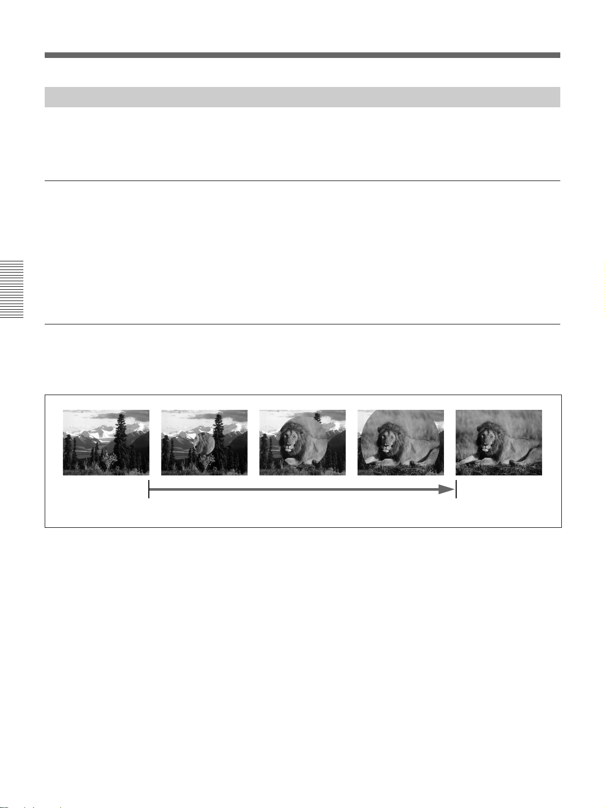
Example Operation (1): Wipe
Setting items
Chapter 3 Basic Operation
Program output
In this example we’ll use the AUTO TRANS button, to make a wipe, with
the new image appearing from the center of the screen.
As an example, we’ll set the control panel as follows.
Background image (the image output before the transition): video
signal connected to the VIDEO INPUT 1 connector
Foreground image (the image output after the transition): video
signal connected to the VIDEO INPUT 2 connector
Effect: wipe (pattern number 24)
Transition time: 30 frames
Start of effect
Executing the above effect produces the following changes in the output
on a program monitor connected to the PGM OUT connector of the
processor unit.
Transition time
End of effect
3-2 Chapter 3 Basic Operation
Page 29
Procedure
LAST X
INS
RST
TITLE
12
EDITOR LUM LUM LUM
DSK EDGE
TRAIL
SHADOW
GPI CRK CRK BORDER BEVELD
EDGE
SET UP MASK MASK MASK SOFT
SHIFT CCR LIGHTING BORDERMATTES
LOCATION
LEARNEDIT
RECALL
HOLD
INPUT
INITIAL
PATTERN
ADJ
PAGE
F1 F2 F3 F4 F5
USER PGM
STATUS EDIT
SNAP SHOT
SET
PATTERN NUMBER
EFFECT
DSK
FTB
SET
TRANS RATE
789
456
123
0
DOWN UP
ENTER
FADE
TO
BLACK
P IN P
DSK
DEL
N/R REV DSK PVWDIRECT
RECALL
DIRECT
PATTERN
CCR TITLE 1
SOURCE
TITLE 2
SOURCE
DSK
FILL
SUPER BG FRGD 2 MEMORY FRAME FREEZ MIX EFFECT
BACKGROUND
BLACK MEMORY INT
VIDEO
TITLE
1234 5678
CUT
AUTO
TRANS
AUXILIARY
BLACK
MEMORY
INT
VIDEO
12345678
FOREGROUND
BLACK
MEMORY
INT
VIDEO
12345678
PATTERN/KEY PAD
8
910
3
2
1
6
5,7
4
Chapter 3 Basic Operation
<Preparation>
<Image selection>
<Effect selection>
1 Pull the fader lever toward you as far as it will go.
2 Press BACKGROUND Bus button 1.
The pressed button lights red, and the video signal connected to the
VIDEO INPUT 1 connector is selected as the background image. The
selected background image appears on the program monitor.
3 Press FOREGROUND Bus button 2.
The pressed button lights amber, and the video signal connected to the
VIDEO INPUT 2 connector is selected as the foreground image.
To check the selected image on the program monitor, move the fader
lever to the opposite end. After checking, return the lever to the
position closest to you.
If a preview monitor is connected, the selected foreground image
appears in the preview monitor.
4 Press the DIRECT PATTERN button, turning it on.
(If it is already lit, omit this step.)
The unit is now in direct pattern selection mode. In this mode, you can
select the eleven patterns assigned to buttons in the pattern/numeric
keypad using the corresponding button.
(Continued)
Chapter 3 Basic Operation 3-3
Page 30
DME Switcher Introduction
5 Press button 9 in the pattern/numeric keypad.
The button lights, and this selects the wipe assigned to this button
(pattern number 24). The PATTERN NUMBER display window
shows “0024”.
<Transition time setting>
Chapter 3 Basic Operation
6 Press the SET button once or twice, so that the EFFECT display
window mode indicator lights.
(If it is already lit, omit this step.)
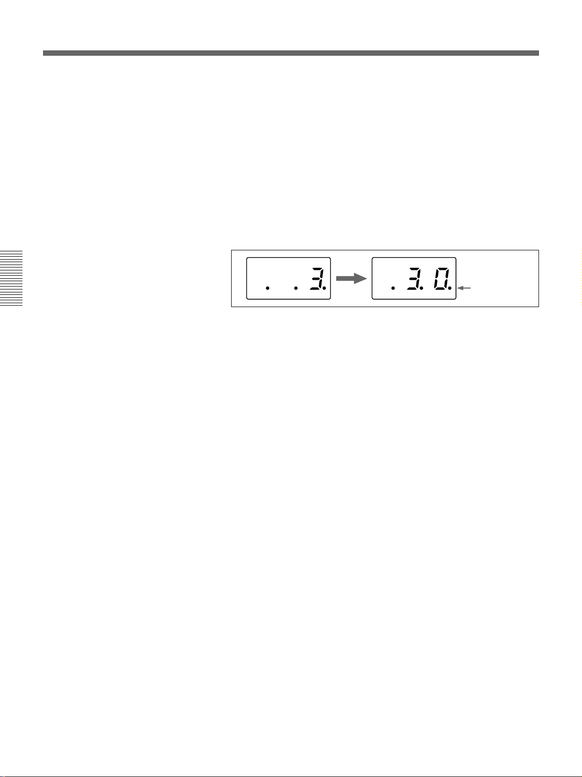
7 In the pattern/numeric keypad, press buttons 3 and 0 in that order.
The TRANS RATE display window shows “.3.0.”.
Dots appear to
the lower right of
the digits
8 Press the ENTER button.
The dots to the lower right of the digits disappear, and the value
entered in step 7 is set as the transition time.
9 Press the EFFECT button, turning it on.
(If it is already lit, omit this step.)
10Press the AUTO TRANS button.
The wipe is carried out over 30 frames, switching from the background
image to the foreground image.
When the transition completes, BACKGROUND bus button 2 is lit
red, and FOREGROUND bus button 1 is lit amber. This indicates that
as a result of the transition, the video signal connected to the VIDEO
INPUT 2 connector is automatically selected as the background image,
and the video signal connected to the VIDEO INPUT 1 connector as
the foreground image.
3-4 Chapter 3 Basic Operation
Page 31

Example Operation (2): Picture-in-Picture
Using the fader lever, we’ll insert the foreground image within the
background image.
We’ll apply a border around the edge of the foreground image.
Setting items
As an example, we’ll set the control panel as follows.
Background image: internal video signal (color background )
Foreground image: video signal connected to the VIDEO INPUT 1
connector
Effect: picture-in-picture (pattern number 1100)
Border: ON
Program output
Executing the above effect produces the following changes in the output
on a program monitor.
Chapter 3 Basic Operation
Background image
Foreground image
Program output
Effect execution
Chapter 3 Basic Operation 3-5
Page 32

DME Switcher Introduction
Procedure
Chapter 3 Basic Operation
<Preparation>
<Image selection>
2
3
8
DSK EDGE
TITLE
12
EDITOR LUM LUM LUM
GPI CRK CRK BORDER BEVELD
SET UP MASK MASK MASK SOFT
SHIFT CCR LIGHTING BORDERMATTES
AUXILIARY
BLACK MEMORY INT
BACKGROUND
BLACK
FOREGROUND
BLACK
TRAIL
SHADOW
EDGE
INITIAL
PATTERN
PAGE
F1 F2 F3 F4 F5
ADJ
CCR TITLE 1
TITLE 2
DSK
SUPER BG FRGD 2 MEMORY FRAME FREEZ MIX EFFECT
SOURCE
SOURCE
FILL
1234 5678
12345678
12345678
TRANS RATE
MEMORY
MEMORY
USER PGM
STATUS EDIT
EFFECT
DSK
FTB
TITLE
VIDEO
INT
CUT
VIDEO
AUTO
INT
VIDEO
TRANS
PATTERN NUMBER
SET
SNAP SHOT
LEARNEDIT
RECALL
HOLD
INPUT
N/R REV DSK PVWDIRECT
RECALL
789
456
123
DOWN UP
0
PATTERN/KEY PAD
LOCATION
5
DIRECT
PATTERN
LAST X
P IN P
ENTER
SET
FADE
TO
BLACK
INS
DEL
RST
6
DSK
7
4
1,9
1 Pull the fader lever toward you as far as it will go.
2 Press the MATTES button in the menu control section, and display
page 1 of the MATTE menu, then with the F1(SELECT) button select
“INT V”.
MATTE
1/2
SELECT
INT V
Lum
0-100
Sat
0-100
Hue
0-99
CH2BRD
BRDMA T
<Effect selection>
P A GE F1 F2 F3 F4 F5
You can change the color of matte color and embossing pattern. For details,
see the section “Adjusting Color Mattes” (page 3-57).
3 Press the BACKGROUND bus INT VIDEO button.
The pressed button lights red, and a color matte is selected as the
background image.
4 Press the FOREGROUND bus button 1.
The pressed button lights amber, and the video signal connected to the
VIDEO INPUT 1 connector is selected as the foreground image.
5 Press the SET button to the right of the PATTERN NUMBER display
window, turning it on.
(If it is already lit, omit this step.)
3-6 Chapter 3 Basic Operation
Page 33

6 In the numeric keypad, press buttons 1, 1, 0, 0, in that order.
The PATTERN NUMBER display window shows “1.1.0.0.”.
Dots appear to the lower right of the digits.
7 Press the ENTER button.
The dots to the lower right of the digits disappear, and picture-inpicture, or pattern number 1100, is selected.
<Border settings>
<Effect execution>
8 In the menu control section, press the BORDER button.
The button lights, enabling the border.
Chapter 3 Basic Operation
You can change the color and width of the border. For details, see the section
“Modifying the Boundary” (page 3-26).
9 Move the fader lever to the opposite end.
Both the BACKGROUND bus INT VIDEO button and the
FOREGROUND bus button 1 light red.
As you move the lever, the picture-in-picture effect takes place, and a
foreground image with a border is inserted into the background image.
Chapter 3 Basic Operation 3-7
Page 34

DME Switcher Introduction
Demonstration
Chapter 3 Basic Operation
The DFS-700/700P is equipped with a demonstration function, which
automatically plays back one hundred effects stored in ROM in the
processor unit.
The effects (which by factory default are snapshots 0 to 99) have been
chosen to demonstrate the features of the DFS-700/700P as effectively as
possible.
For maximum effect, the demonstration function uses the signals
connected to VIDEO INPUT connectors 1 and 2, and the internal video
signal.
USER PGM
EDITOR LUM LUM LUM
GPI CRK CRK BORDER BEVELD
SET UP MASK MASK MASK SOFT
SHIFT CCR LIGHTING BORDERMATTES
AUXILIARY
BLACK MEMORY INT
BACKGROUND
BLACK
FOREGROUND
BLACK
TRAIL
SHADOW
EDGE
INITIAL
PATTERN
PAGE
F1 F2 F3 F4 F5
ADJ
CCR TITLE 1
TITLE 2
DSK
SUPER BG FRGD 2 MEMORY FRAME FREEZ MIX EFFECT
SOURCE
SOURCE
FILL
1234 5678
12345678
12345678
TRANS RATE
MEMORY
MEMORY
DSK EDGE
TITLE
12
EFFECT
DSK
FTB
SET
TITLE
VIDEO
INT
CUT
VIDEO
AUTO
INT
VIDEO
TRANS
STATUS EDIT
PATTERN NUMBER
SNAP SHOT
LEARNEDIT
RECALL
HOLD
INPUT
N/R REV DSK PVWDIRECT
RECALL
789
456
123
DOWN UP
0
PATTERN/KEY PAD
LOCATION
DIRECT
PATTERN
LAST X
P IN P
ENTER
SET
FADE
TO
BLACK
INS
DEL
RST
DSK
Pattern/numeric
keypad
To start the demonstration
AUTO TRANS button
Buttons used for the demonstration
In the pattern/numeric keypad, hold down buttons 1 and 9, and press the
AUTO TRANS button.
The one hundred effects stored in ROM are played back continuously, and
repeated until you press the AUTO TRANS button once more. During the
demonstration, the buttons on the pattern/numeric keypad light in turn in
the clockwise direction.
During the demonstration, the control panel does not accept any operations
other than pressing the AUTO TRANS button.
Demonstration with user-registered snapshots
It is also possible to have a demonstration with user-registered snapshots.
In this case, hold down buttons 3 and 7 in the pattern/numeric keypad, and
press the AUTO TRANS button. During the demonstration, the buttons on
the pattern/numeric keypad light in turn in the counterclockwise direction.
3-8 Chapter 3 Basic Operation
Page 35

To end the demonstration
Press the AUTO TRANS button once more.
The demonstration ends, and the control panel settings are those of the last
effect in the demonstration.
Chapter 3 Basic Operation
Chapter 3 Basic Operation 3-9
Page 36

DME Switcher Introduction
Using the Menus
This unit incorporates menus for various effect settings and internal color
matte settings, and also a setup menu for system settings.
This section describes the basic menu operation.
Accessing a menu
Chapter 3 Basic Operation
Menu control section
TITLE
DSK EDGE
12
EDITOR LUM LUM LUM
GPI CRK CRK BORDER BEVELD
SET UP MASK MASK MASK SOFT
SHIFT CCR LIGHTING BORDERMATTES
AUXILIARY
BLACK MEMORY INT
BACKGROUND
BLACK
FOREGROUND
BLACK
TRAIL
SHADOW
EDGE
CCR TITLE 1
TITLE 2
DSK
SOURCE
SOURCE
FILL
12345678
12345678
12345678
Menu display
INITIAL
PATTERN
PAGE
F1 F2 F3 F4 F5
ADJ
TRANS RATE
SUPER BG FRGD 2 MEMORY FRAME FREEZ MIX EFFECT
TITLE
VIDEO
INT
MEMORY
CUT
VIDEO
AUTO
INT
MEMORY
VIDEO
TRANS
USER PGM
SNAP SHOT
STATUS EDIT
LEARNEDIT
RECALL
LOCATION
HOLD
EFFECT
DSK
FTB
SET
PATTERN NUMBER
INPUT
N/R REV DSK PVWDIRECT
RECALL
789
456
123
DOWN UP
0
PATTERN/KEY PAD
DIRECT
PATTERN
LAST X
P IN P
ENTER
SET
FADE
TO
BLACK
INS
DEL
DSK
RST
Press one of the buttons in the menu control section.
For example, to recall the menu for internal color matte settings, press the
MATTES button in the menu control section. The MATTE menu appears
in the menu display in the effect control section.
In this manual, menus are shown in a tabular format. The following
example shows the MATTE menu.
Menu page number
“1/2” means that this is the
first of two pages.
Menu name
MATTE
P 1/2
A “P” appears
P A GE F1 F2 F3 F4 F5
here when preread
editing is on.
Refers to the PAGE button.
3-10 Chapter 3 Basic Operation
SELECT
INT V
Lum
0-100
Sat
0-100
Refers to buttons and
knobs F1 to F5.
Hue
0-99
CH2BRD
BRDMA T
Setting items
(parameters)
Values for the settings
“0-100” indicates a numerical range.
Page 37

Changing settings
•For settings with values shown in letters, press the corresponding one of
buttons F1 to F5.
In the text, this is shown as “the F1(SELECT) button,” with the setting
name after the button name F1 to F5.
•To change a setting with a numerical value, turn the corresponding one of
control knobs F1 to F5.
In the text, this is shown as “the F2(Lum) knob,” with the setting name
after the knob name F1 to F5.
•In the setup menu, when an item has a plus sign in front, hold down the F
button (F4 or F5) and turn the corresponding knob.
For example, in page 3/8 of the setup menu, to change the setting for F4
[+H-pos], hold down the F4 button and turn the F4 knob.
To change the menu page
Press the PAGE button.
Buttons of the menu control section which light when pressed
When you press one of these buttons, it lights, and the settings in the menu
recalled by the button are reflected in the monitor display. To avoid this,
for example just to check the settings in a menu, hold down the SHIFT
button while pressing the menu button.
Chapter 3 Basic Operation
Chapter 3 Basic Operation 3-11
Page 38

Selecting Images
Background Image and Foreground Image
Background and foreground in a transition effect
In a transition from one image to another, the old image is referred to as
the “background image”. The new image, which replaces the old image, is
referred to as the “foreground image”.
When a transition completes, the background image and foreground image
are interchanged.
B: background image F: foreground image
BF FB
Chapter 3 Basic Operation
Example transition effect: wipe
Background and foreground in an animation effect
In an animation effect, in which an effect pattern is inserted in the image or
moved about on the image, the background image is the background to the
effect, and the inserted effect is referred to as the “foreground image”.
When an animation effect completes, the background image and
foreground image are not interchanged.
B: background image F: foreground image
B
B
Example animation effect: picture-in-picture
F
3-12 Chapter 3 Basic Operation
Page 39

Selecting the background image and foreground image
As the background image and foreground image you can select any of the
video signals connected to the VIDEO INPUT 1 to 8 connectors of the
processor unit (corresponding to BACKGROUND/FOREGROUND bus
buttons 1 to 8), a freeze frame stored in the frame memory (MEMORY
button), or internal pattern signal (INT VIDEO button).
DSK EDGE
TITLE
12
1
EDITOR LUM LUM LUM
GPI CRK CRK BORDER BEVELD
SET UP MASK MASK MASK SOFT
SHIFT CCR LIGHTING BORDERMATTES
AUXILIARY
BLACK MEMORY INT
BACKGROUND
BLACK
FOREGROUND
BLACK
TRAIL
SHADOW
EDGE
INITIAL
PATTERN
ADJ
CCR TITLE 1
TITLE 2
DSK
SUPER BG FRGD 2 MEMORY FRAME FREEZ MIX EFFECT
SOURCE
SOURCE
FILL
1234 5678
12345678
12345678
2
PAGE
F1 F2 F3 F4 F5
TRANS RATE
VIDEO
INT
MEMORY
VIDEO
INT
MEMORY
VIDEO
TRANS
USER PGM
SNAP SHOT
STATUS EDIT
LEARNEDIT
RECALL
LOCATION
HOLD
EFFECT
DSK
FTB
SET
TITLE
CUT
AUTO
PATTERN NUMBER
INPUT
N/R REV DSK PVWDIRECT
RECALL
789
456
123
DOWN UP
0
PATTERN/KEY PAD
DIRECT
PATTERN
LAST X
ENTER
SET
FADE
TO
BLACK
INS
DEL
P IN P
DSK
RST
Chapter 3 Basic Operation
1 To select the background image, press one of BACKGROUND bus
buttons 1 to 8.
The pressed button lights red.
2 To select the foreground image, press one of FOREGROUND bus
buttons 1 to 8.
The pressed button lights amber.
Program output and lit button colors
The BACKGROUND bus buttons and FOREGROUND bus buttons light
in two colors, depending on whether or not the corresponding image is
present in the current program monitor output (on a video monitor
connected to the PGM OUT connector).
•A button lights red when the image is present in the program monitor
output.
•A button lights amber when the image is not present in the program
monitor output.
Chapter 3 Basic Operation 3-13
Page 40

Selecting Images
Switching the internal video signal selected by the INT VIDEO button
To switch the internal video signal selected by pressing the INT VIDEO
button on either the background bus or foreground bus, use the following
procedure.
TITLE
DSK EDGE
12
Chapter 3 Basic Operation
1
EDITOR LUM LUM LUM
GPI CRK CRK BORDER BEVELD
SET UP MASK MASK MASK SOFT
SHIFT CCR LIGHTING BORDERMATTES
AUXILIARY
BLACK MEMORY INT
BACKGROUND
BLACK
FOREGROUND
BLACK
TRAIL
SHADOW
EDGE
INITIAL
PATTERN
PAGE
F1 F2 F3 F4 F5
ADJ
CCR TITLE 1
TITLE 2
DSK
SUPER BG FRGD 2 MEMORY FRAME FREEZ MIX EFFECT
SOURCE
SOURCE
FILL
1234 5678
12345678
12345678
TRANS RATE
MEMORY
MEMORY
3
USER PGM
SNAP SHOT
STATUS EDIT
LEARNEDIT
RECALL
LOCATION
HOLD
EFFECT
DSK
FTB
SET
TITLE
VIDEO
INT
CUT
VIDEO
AUTO
INT
VIDEO
TRANS
PATTERN NUMBER
INPUT
N/R REV DSK PVWDIRECT
RECALL
789
456
123
DOWN UP
0
PATTERN/KEY PAD
DIRECT
PATTERN
LAST X
ENTER
SET
INS
DEL
P IN P
RST
2
FADE
TO
BLACK
DSK
3
1 Press the MATTES button in the menu control section.
Page 1 of the MATTE menu appears.
2 Press the PAGE button in the effect control section, to display page 2
of the MATTE menu, then press the F4(INTVID) button to select the
desired signal.
MATTE
2/2
P A GE F1 F2 F3 F4 F5
You can select any of the following three possibilities.
Matte: color background signal. In the following step 3, you can select
any of plain, or 79 different embossed patterns.
You can adjust the color of the color background signal as desired. For
details, see the section “Adjusting Color Mattes” (page 3-57).
Bar: color bars
Grid: a grid pattern
FROM
INT V
TO
BORD
COPY
EXEC
INTVID
Matte
PTN
1-80
3-14 Chapter 3 Basic Operation
3 If you have selected a color background signal carry out either of the
following.
•Hold down the INT VIDEO button in the background bus or
foreground bus, and in the pattern/numeric keypad press the UP or
DOWN button.
Each time you press, the pattern changes, and the new pattern appears
on the program monitor.
•Turn the F5(PTN) knob.
Page 41

Previewing the image after an effect is executed
Select the background image and foreground image, and set up the effect,
then move the fader lever to the opposite end.
You can now check on the program monitor the result of carrying out the
currently set effect.
If a preview monitor is connected, you can check the foreground image on
the preview monitor.
Chapter 3 Basic Operation
Chapter 3 Basic Operation 3-15
Page 42

Selecting Images
Selecting Signals Output to the Auxiliary Bus
Chapter 3 Basic Operation
Delegation buttons
TITLE
12
EDITOR LUM LUM LUM
GPI CRK CRK BORDER BEVELD
SET UP MASK MASK MASK SOFT
SHIFT CCR LIGHTING BORDERMATTES
CCR TITLE 1
AUXILIARY
BLACK MEMORY INT
12345678
BACKGROUND
BLACK
12345678
FOREGROUND
BLACK
12345678
DSK EDGE
TRAIL
SHADOW
EDGE
INITIAL
PATTERN
ADJ
TITLE 2
DSK
SUPER BG FRGD 2 MEMORY FRAME FREEZ MIX EFFECT
SOURCE
SOURCE
FILL
PAGE
F1 F2 F3 F4 F5
TRANS RATE
VIDEO
INT
MEMORY
VIDEO
INT
MEMORY
VIDEO
TRANS
USER PGM
SNAP SHOT
STATUS EDIT
LEARNEDIT
RECALL
LOCATION
HOLD
EFFECT
DSK
FTB
SET
TITLE
CUT
AUTO
PATTERN NUMBER
INPUT
N/R REV DSK PVWDIRECT
RECALL
789
456
123
DOWN UP
0
PATTERN/KEY PAD
DIRECT
PATTERN
LAST X
P IN P
ENTER
SET
FADE
TO
BLACK
INS
DEL
DSK
RST
AUXILIARY buttons
To select the signal to be output to the auxiliary bus, press the desired
AUXILIARY button (BLACK, 1 to 8, MEMORY, or INT VIDEO),
turning it on.
To specify the function for which the selected signal is used, press one of
the delegation buttons, turning it on.
CCR button: use for color correction.
TITLE 1 SOURCE button: use as the key source signal for title key 1.
TITLE 2 SOURCE button: use as the key source signal for title key 2.
DSK FILL button: use as key fill for the downstream keyer.
SUPER BG button: use as background for 3D effects, two-channel
DME effects and so on.
FRGD 2 button: use as the second foreground channel for 3D effects,
two-channel DME effects and so on.
MEMORY button: capture in frame memory.
3-16 Chapter 3 Basic Operation
Page 43

Selecting an Effect
This section describes the types of effects you can use on this system, and
how to select an effect.
Types of Effect
The DFS-700/700P has more than 450 built-in effect patterns provided as
standard.
Each pattern is identified by a number, and the patterns are grouped
together under headings such as “wipe” and “picture-in-picture”.
Transition effects and animation effects
Effects are broadly divided into transition effects and animation effects.
Transition effects: in these effects the background image is completely
Animation effects: in these effects, for example, the foreground image is
replaced by the foreground image. When the effect completes, the
colors in which the BACKGROUND and FOREGROUND bus
buttons are lit become the reverse of those before the effect.
inserted in the background image, and moved around. The foreground
image does not completely replace the background image, and the
colors in which the BACKGROUND and FOREGROUND bus
buttons are lit stay the same.
Chapter 3 Basic Operation
For the differences between transition and animation effects, see the section
“Background Image and Foreground Image” (page 3-12).
Modifications to effects
Depending on the effect pattern, the following modifications can be added.
•You can add a border to the boundary between the background image and
foreground image, or blur the boundary.
•You can change the pattern position and size.
For details of the modifications that can be applied to the effect patterns, see the
section “Effect Pattern Variant Forms and Decorations” (page A-22).
•You can change a pattern by changing its parameters. (Effects which can
be changed by setting parameters are referred to as “user modifiable
effects”.)
Chapter 3 Basic Operation 3-17
Page 44

Selecting an Effect
Example Effects
7
Pattern number: 1
Effect type: wipe
Chapter 3 Basic Operation
Motion type: transition
This section shows as examples the effect patterns (“direct patterns”)
which you can access simply by pressing a button in the pattern/numeric
keypad. Note that the effect patterns shown below are the factory default
assignments, and you can change the patterns assigned to buttons 0 to 9
and P IN P/RST.
For details of how to change the assignments, see the section “Changing Direct
Pattern Assignments” (page 4-1).
8
Pattern number: 9
Effect type: wipe
Motion type: transition
9
Pattern number: 24
Effect type: wipe
Motion type: transition
The foreground image appears from the left, and wipes over the
background image to the right.
The foreground image appears from the upper left corner, and wipes over
the background image to the lower right.
The foreground image appears as a circle in the center of the image, and
this circle grows, wiping over the background image.
3-18 Chapter 3 Basic Operation
Page 45

4
Pattern number: 700
Effect type: matrix wipe
Motion type: transition
5
Pattern number: 1300
Effect type: slide
Motion type: transition
6
Pattern number: 1700
Effect type: 3D rotation
Motion type: transition
The foreground image appears in the upper left corner, and fills the screen
in a series of vertical strips.
Chapter 3 Basic Operation
The foreground image appears from the right, and slides over the
background image to the left.
1
Pattern number: 1902
Effect type: flip
Motion type: transition
The foreground image appears as a door rotating toward the viewer to
close, and covers the background. When the door is completely closed, the
foreground fills the screen.
The image rotates about a vertical axis as though a panel with the
background on one side. When the panel reaches 90 degrees to the plane of
the screen, the foreground image appears on the other side, and completely
fills the screen when the transition ends.
Chapter 3 Basic Operation 3-19
Page 46

Selecting an Effect
2
Pattern number: 2100
Effect type: page turn
Motion type: transition
3
Pattern number: 2200
Effect type: sphere
Motion type: transition
Chapter 3 Basic Operation
The foreground image appears as though progressively covering the
background image.
The foreground image appears in a ball shape in the upper right. It
“bounces” on the bottom of the screen, then when it reaches the top, turns
into a plane and fills the screen, covering the background image.
P IN P
RST
Pattern number: 1100
Effect type: picture-in-picture
Motion type: animation
0
Pattern number: 2260
Effect type: ripple
Motion type: transition
The foreground image appears in the center as a rectangle, of the same
aspect ratio as the screen, and grows larger until it covers the background
image.
The foreground image appears as from within the ripples, finally covering
the whole screen with no movement.
3-20 Chapter 3 Basic Operation
Page 47

Nonlinear effects
These effects include effects such as ripples, under names such as lens,
burst, explosion, swirl, and rings.
Two-channel DME effects
Ripple
Explosion
Lens Swirl
These effects combine two foreground images with the background image.
They include two-channel picture-in-picture, two-picture intersect, twopicture brick, two-channel page turn, and so on.
Chapter 3 Basic Operation
Two-channel picture-in-picture Two-picture Intersect Masked flip
Note
To use two-channel DME effects requires the optional BKDF-711 2nd
Channel DME Board.
Chapter 3 Basic Operation 3-21
Page 48

Selecting an Effect
3D mapping effects
These effects use nonlinear image processing techniques. They include 3D
page turn, 3D beveled edge, and so on.
Chapter 3 Basic Operation
Three-picture cube
Note
3D wave
3D page turn
Multi-cube
3D beveled edge
3D cylinder
Using 3D mapping effects requires the optional BKDF-712 3D Video
Mapping Effects Board.
Using the three-picture cube effect also requires the optional BKDF-711
2nd Channel DME Board.
3-22 Chapter 3 Basic Operation
Page 49

Selection in Direct Pattern Selection Mode
In the direct pattern selection mode, pressing any button (other than INS,
DEL, UP, DOWN, or ENTER) in the pattern/numeric keypad directly
selects an effect pattern.
For details of the effects assigned by factory default to the buttons in the pattern/
numeric keypad, see the previous section “Example Effects” (page 3-18).
Procedure
To select an effect pattern in the direct pattern selection mode, use the
following procedure.
Note
If the EDIT button in the user program section (see page 2-11) is lit, first
press it, turning it off.
USER PGM
TITLE
DSK EDGE
12
EDITOR LUM LUM LUM
GPI CRK CRK BORDER BEVELD
SET UP MASK MASK MASK SOFT
SHIFT CCR LIGHTING BORDERMATTES
AUXILIARY
BLACK MEMORY INT
BACKGROUND
BLACK
FOREGROUND
BLACK
TRAIL
SHADOW
EDGE
INITIAL
PATTERN
PAGE
F1 F2 F3 F4 F5
ADJ
CCR TITLE 1
TITLE 2
DSK
SUPER BG FRGD 2 MEMORY FRAME FREEZ MIX EFFECT
SOURCE
SOURCE
FILL
1234 5678
12345678
12345678
TRANS RATE
MEMORY
MEMORY
EFFECT
DSK
FTB
SET
TITLE
VIDEO
INT
CUT
VIDEO
AUTO
INT
VIDEO
TRANS
STATUS EDIT
PATTERN NUMBER
SNAP SHOT
LEARNEDIT
RECALL
HOLD
INPUT
N/R REV DSK PVWDIRECT
RECALL
789
456
123
DOWN UP
0
PATTERN/KEY PAD
LOCATION
PATTERN
SET
DIRECT
LAST X
INS
DEL
P IN P
RST
ENTER
1
FADE
TO
BLACK
2
DSK
1 Press the DIRECT PATTERN button, turning it on.
The unit is now in direct pattern selection mode.
Chapter 3 Basic Operation
2 In the pattern/numeric keypad, press the button assigned to the desired
effect pattern, turning it on.
This selects the effect assigned to the button, and the pattern number
appears in the PATTERN NUMBER display window.
Chapter 3 Basic Operation 3-23
Page 50

Selecting an Effect
Selection in Pattern Number Specification Mode
Procedure
Chapter 3 Basic Operation
In the pattern number specification mode, you select the desired effect
pattern by entering the number.
To select an effect pattern in the pattern number specification mode, use
the following procedure.
Note
If the EDIT button in the user program section (see page 2-11) is lit, first
press it, turning it off.
USER PGM
EDITOR LUM LUM LUM
GPI CRK CRK BORDER BEVELD
SET UP MASK MASK MASK SOFT
SHIFT CCR LIGHTING BORDERMATTES
AUXILIARY
BLACK MEMORY INT
BACKGROUND
BLACK
FOREGROUND
BLACK
TRAIL
SHADOW
EDGE
INITIAL
PATTERN
PAGE
F1 F2 F3 F4 F5
ADJ
CCR TITLE 1
TITLE 2
DSK
SOURCE
1234 5678
12345678
12345678
SUPER BG FRGD 2 MEMORY FRAME FREEZ MIX EFFECT
SOURCE
FILL
TRANS RATE
MEMORY
MEMORY
DSK EDGE
TITLE
12
EFFECT
DSK
FTB
SET
TITLE
VIDEO
INT
CUT
VIDEO
AUTO
INT
VIDEO
TRANS
STATUS EDIT
PATTERN NUMBER
SNAP SHOT
LEARNEDIT
RECALL
HOLD
INPUT
N/R REV DSK PVWDIRECT
RECALL
789
456
123
DOWN UP
0
PATTERN/KEY PAD
LOCATION
DIRECT
PATTERN
LAST X
P IN P
ENTER
SET
INS
DEL
RST
1
FADE
TO
BLACK
2
DSK
3
1 Press the SET button, turning it on.
2 Enter the desired pattern number using buttons 0 to 9 on the pattern/
numeric keypad.
The number you entered appears in the PATTERN NUMBER display
window. Dots appear at the lower right of each digit, indicating that
the entry is not yet confirmed.
3-24 Chapter 3 Basic Operation
3 Press the ENTER button.
The dots to the lower right of the digits in the PATTERN NUMBER
display window disappear, confirming the pattern number.
Page 51

If you enter a wrong number
Before pressing the ENTER button press the P IN P/RST button to cancel
the wrong number, then enter the correct number.
Note
If you enter an invalid number (a number with no corresponding pattern),
this is automatically corrected to the closest valid number larger than the
number you entered. However, if you enter a number larger than 9309 this
is corrected to pattern number 0001.
Adjusting the number before confirming
To increment the number by one, press the UP button. Hold down the UP
button to increase the number continuously.
To decrement the number by one, press the DOWN button. Hold down the
DOWN button to decrease the number continuously.
Chapter 3 Basic Operation
Chapter 3 Basic Operation 3-25
Page 52

Modifying the Boundary — Border, Soft Edge,
Beveled Edge, and Crop
You can apply a border to the boundary between the foreground image and
background image, or mask unwanted parts of the image.
There are four effects for modifying the boundary, as follows. You can use
all four simultaneously.
Border: apply a border to the image boundary.
Soft edge: blur the image boundary.
Beveled edge: apply a bevel to the image boundary.
Crop: adjust the image boundary position, to eliminate unwanted parts.
(For picture-in-picture and other effects in which a reduced image is
used, reduce noise on the periphery of the image.)
Note
Depending on the effect pattern, you may not be able to apply the above
effects. For details, see the section “Effect Pattern Variant Forms and
Decorations” (page A-22).
Chapter 3 Basic Operation
Procedure
EDGE section
EDITOR LUM LUM LUM
GPI CRK CRK BORDER BEVELD
SET UP MASK MASK MASK SOFT
SHIFT CCR LIGHTING BORDERMATTES
AUXILIARY
BLACK MEMORY INT
BACKGROUND
BLACK
FOREGROUND
BLACK
TRAIL
SHADOW
EDGE
INITIAL
PATTERN
ADJ
CCR TITLE 1
TITLE 2
DSK
SUPER BG FRGD 2 MEMORY FRAME FREEZ MIX EFFECT
SOURCE
SOURCE
FILL
1234 5678
12345678
12345678
DSK EDGE
TITLE
12
Controls used in modifying the boundary
To apply a border
Use the following procedure.
Effect control section
PAGE
F1 F2 F3 F4 F5
TRANS RATE
VIDEO
INT
MEMORY
VIDEO
INT
MEMORY
VIDEO
TRANS
USER PGM
SNAP SHOT
STATUS EDIT
LEARNEDIT
RECALL
LOCATION
HOLD
EFFECT
DSK
FTB
SET
TITLE
CUT
AUTO
PATTERN NUMBER
INPUT
N/R REV DSK PVWDIRECT
RECALL
789
456
123
DOWN UP
0
PATTERN/KEY PAD
DIRECT
PATTERN
LAST X
P IN P
ENTER
SET
FADE
TO
BLACK
INS
DEL
DSK
RST
3-26 Chapter 3 Basic Operation
1 Press the BORDER button in the EDGE section, turning it on, and
display page 1 of the EDGE menu.
EDGE
1/2
PAGE F1 F2 F3 F4 F5
Border
0-100
Soft
0-100
BvlWid
–100-100
BVLTYP
01-20
BvlInt
0-100
2 Turn the F1(Border) knob, to set the width of the border.
Page 53

To blur the image boundary
Use the following procedure.
1 Press the SOFT button in the EDGE section, turning it on, and display
page 1 of the EDGE menu.
EDGE
1/2
PAGE F1 F2 F3 F4 F5
Border
0-100
Soft
0-100
BvlWid
–100-100
BVLTYP
01-20
BvlInt
0-100
2 Turn the F2(Soft) knob, to set the degree of boundary blurring.
To apply a beveled edge to the image boundary
Use the following procedure.
1 Press the BEVELD EDGE button in the EDGE section, turning it on,
and display page 1 of the EDGE menu.
EDGE
1/2
PAGE F1 F2 F3 F4 F5
Border
0-100
Soft
0-100
BvlWid
–100-100
BVLTYP
01-20
BvlInt
0-100
2 Turn knobs F3(BvlWid), F4(BVLTYP), and F5(BvlInt) to set the
width, type, and contrast of the beveled edge.
Chapter 3 Basic Operation
To remove unwanted portions of the image
Use the following procedure.
1 Press any one of the BORDER, SOFT, and BEVELD EDGE buttons,
turning it on, and display page 2 of the EDGE menu. (Press the PAGE
button to change the page.)
EDGE
2/2
PAGE F1 F2 F3 F4 F5
CROP
AUTO
Left
–400-400
Right
–400-400
Top
–300-300
Bottom
–300-300
2 To adjust the image boundary manually, press the F1(CROP) button to
select “MANUAL”.
3 Turn the F2(Left), F3(Right), F4(Top), F5(Bottom) knobs, to adjust the
four sides of the image boundary.
Note
If in step 2 you set F1(CROP) to “AUTO”, the automatic adjustment for
the particular effect pattern is carried out. Selecting “OFF” disables the
cropping.
When effect parameters are already adjusted
When parameters of a border, soft edge, beveled edge, or crop effect are
already adjusted, simply pressing any one of the BORDER, SOFT, and
BEVELD EDGE buttons in the EDGE section to turn it on allows you to
apply the selected effects to the effect pattern.
Chapter 3 Basic Operation 3-27
Page 54

Modifying the Boundary — Border, Soft Edge, Beveled Edge, and Crop
Indications in the EDGE menu with square brackets [ ]
The parameters in the EDGE menu for functions which are turned off
appear in square brackets [ ].
For example, when the border function is off, when you display the EDGE
menu the setting for Border appears in square brackets.
In this state the knob adjustment is still valid. When you press the
BORDER button, turning the function on, the new setting is reflected
accordingly.
Chapter 3 Basic Operation
3-28 Chapter 3 Basic Operation
Page 55

Changing the Pattern Position and Size —
Location (X)(Y)(Z)
You can adjust the position and size of an effect pattern when inserting a
foreground image into the background image.
Note
For some effect patterns it is not possible to change their position and size.
If pressing the LOCATION button does not turn it on, it means that one of
those effect patterns is selected.
For details of whether position and size adjustment is possible for an effect, see
the section “Effect Pattern Variant Forms and Decorations” (page A-22).
Procedure
To change the position and size of an effect pattern use the following
procedure.
USER PGM
TITLE
DSK EDGE
12
EDITOR LUM LUM LUM
GPI CRK CRK BORDER BEVELD
SET UP MASK MASK MASK SOFT
SHIFT CCR LIGHTING BORDERMATTES
AUXILIARY
BLACK MEMORY INT
BACKGROUND
BLACK
FOREGROUND
BLACK
TRAIL
SHADOW
EDGE
INITIAL
PATTERN
PAGE
ADJ
CCR TITLE 1
TITLE 2
DSK
SUPER BG FRGD 2 MEMORY FRAME FREEZ MIX EFFECT
SOURCE
SOURCE
FILL
1234 5678
12345678
12345678
F1 F2 F3 F4 F5
TRANS RATE
MEMORY
MEMORY
EFFECT
DSK
FTB
SET
TITLE
VIDEO
INT
CUT
VIDEO
AUTO
INT
VIDEO
TRANS
STATUS EDIT
PATTERN NUMBER
SNAP SHOT
LEARNEDIT
RECALL
HOLD
INPUT
N/R REV DSK PVWDIRECT
RECALL
789
456
123
DOWN UP
0
PATTERN/KEY PAD
LOCATION
DIRECT
PATTERN
LAST X
P IN P
ENTER
2
3
SET
BLACK
INS
DEL
RST
1
FADE
TO
DSK
1 After checking in the section “Effect Pattern Variant Forms and
Decorations” (page A-22), select an effect pattern for which it is
possible to change the position and size.
2 To move the pattern horizontally (x-axis) or vertically (y-axis), move
the joystick in the location section.
Chapter 3 Basic Operation
Y-axis (+)
X-axis (–) X-axis (+)
Y-axis (–)
Joystick
(continued)
Chapter 3 Basic Operation 3-29
Page 56

Changing the Pattern Position and Size — Location (X)(Y)(Z)
3 To move the pattern in the depth direction (z-axis), turn the Z-knob in
the location section.
Chapter 3 Basic Operation
Z-knob
3-30 Chapter 3 Basic Operation
Page 57

Modifying the Pattern — User Modifiable Effects
User modifiable effects are those effects for which you can modify the
effect pattern by varying the parameters. The variable parameters vary
from effect to effect.
For the pattern number of user modifiable effects, and the variable parameters,
see the section “Effect Control Parameter List” (page A-5)
Procedure
To modify the effect pattern by varying the parameters, use the following
procedure.
USER PGM
TITLE
DSK EDGE
12
EDITOR LUM LUM LUM
GPI CRK CRK BORDER BEVELD
SET UP MASK MASK MASK SOFT
SHIFT CCR LIGHTING BORDERMATTES
AUXILIARY
BLACK MEMORY INT
BACKGROUND
BLACK
FOREGROUND
BLACK
TRAIL
SHADOW
EDGE
INITIAL
PATTERN
PAGE
F1 F2 F3 F4 F5
ADJ
CCR TITLE 1
TITLE 2
DSK
SUPER BG FRGD 2 MEMORY FRAME FREEZ MIX EFFECT
SOURCE
SOURCE
FILL
1234 5678
12345678
12345678
TRANS RATE
MEMORY
MEMORY
EFFECT
DSK
FTB
SET
TITLE
VIDEO
INT
CUT
VIDEO
AUTO
INT
VIDEO
TRANS
STATUS EDIT
PATTERN NUMBER
SNAP SHOT
LEARNEDIT
RECALL
HOLD
INPUT
N/R REV DSK PVWDIRECT
RECALL
789
456
123
DOWN UP
0
PATTERN/KEY PAD
LOCATION
DIRECT
PATTERN
LAST X
P IN P
ENTER
SET
INS
DEL
RST
2
Chapter 3 Basic Operation
1
FADE
TO
BLACK
DSK
1 After checking in the section “Effect Control Parameter List” (page A-
5), select a user modifiable effect.
The variable parameters of the selected effect appear in the menu
display.
If the selected effect has no variable parameters, the menu display
shows a message “No Adjustable Parameter”.
2 Using knobs and buttons F1 to F5, set the parameters.
Chapter 3 Basic Operation 3-31
Page 58

Modifying the Pattern — User Modifiable Effects
Example of user modifiable effect parameters
As an example, if you select mosaic (pattern number 1016), the following
parameters appear in the menu display.
1016
1/1
PAGE F1 F2 F3 F4 F5
For the effect of the parameters, see the following figure.
Chapter 3 Basic Operation
Size
0-100
Aspect
0-100
Soft
0-100
F1(Size): size of a mosaic cell
F2(Aspect): aspect ratio of a mosaic cell
MskAsp
0-100
TYPE
FLAT
F4(MskAsp): aspect ratio of area to
which mosaic is applied
Parameters for mosaic (pattern number 1016)
3-32 Chapter 3 Basic Operation
Page 59

Inserting Characters and Graphics (1) — Title Key
You can insert (or superimpose) text and graphics into the background
image while applying effects. You can use either a luminance key or a
chroma key for this insertion.
Luminance Key
In a luminance key, a certain luminance level in the foreground image is
used as the threshold for creating the key signal, and the corresponding
part of the foreground image is inserted into the background image.
Normally the foreground image is on a black background, consisting of
bright text to be inserted in the background image.
Background image
Composite image formed by
luminance keying (program output)
Foreground image
Two-channel luminance keying
With the optional BKDF-711 2nd Channel DME Board installed, you can
also use a second luminance key channel.
When using two luminance keys, you must make both title 1 and title 2
settings in the TITLE section of the menu control section. Note that to
select the foreground signal used for the second luminance key, in the
delegation section press the FRGD 2 button, turning it on, then select the
desired video signal with one of the AUXILIARY buttons.
Chapter 3 Basic Operation
Chapter 3 Basic Operation 3-33
Page 60

Inserting Characters and Graphics (1) — Title Key
Procedure
To insert text and graphics in a background image by means of a
luminance key, use the following procedure.
TITLE
12
EDITOR LUM LUM LUM
GPI CRK CRK BORDER BEVELD
SET UP MASK MASK MASK SOFT
SHIFT CCR LIGHTING BORDERMATTES
CCR TITLE 1
SOURCE
AUXILIARY
1
Chapter 3 Basic Operation
BLACK MEMORY INT
1234 5678
BACKGROUND
BLACK
12345678
FOREGROUND
BLACK
12345678
2
DSK EDGE
TRAIL
SHADOW
EDGE
INITIAL
PATTERN
ADJ
TITLE 2
DSK
SUPER BG FRGD 2 MEMORY FRAME FREEZ MIX EFFECT
SOURCE
FILL
64
PAGE
F1 F2 F3 F4 F5
TRANS RATE
VIDEO
INT
MEMORY
VIDEO
INT
MEMORY
VIDEO
TRANS
USER PGM
SNAP SHOT
STATUS EDIT
LEARNEDIT
RECALL
LOCATION
HOLD
EFFECT
DSK
FTB
SET
TITLE
CUT
AUTO
PATTERN NUMBER
INPUT
N/R REV DSK PVWDIRECT
RECALL
789
456
123
DOWN UP
0
PATTERN/KEY PAD
DIRECT
PATTERN
LAST X
P IN P
ENTER
SET
FADE
TO
BLACK
INS
DEL
DSK
RST
3
5
1 With the BACKGROUND bus buttons, select the background image.
The selected background image appears on the program monitor.
2 With the FOREGROUND bus buttons, select the foreground image.
If a preview monitor is connected, the selected foreground image
appears in the preview monitor.
3 Select the effect pattern, and press the TITLE button in the effect
transition section, turning it on.
Note
Depending on the effect pattern, it may not be possible to use a
luminance key. If such a pattern is selected, the TITLE button does not
light. Check the “TITLE” column of the table in the section “Effect
Pattern Variant Forms and Decorations” (page A-22), and select a
pattern for which this shows a check mark ( ).
When the TITLE button lights, the N/R button also automatically
lights, indicating that the system is in N/R (normal/reverse) mode.
While the TITLE button is lit, it is not possible to switch out of N/R
mode.
3-34 Chapter 3 Basic Operation
Page 61

4 In the TITLE section of the menu control section, press a LUM button,
turning it on.
The luminance key menu appears in the menu display. In the following
example, the LUM button in column 1 is lit.
T1LUM
1/1
PAGE F1 F2 F3 F4 F5
Clip
0-100
Gain
0-100
INVERT
OFF
FILL
VIDEO
Densty
0-100
5 Either press the CUT button in the effect transition section, or move
the fader lever.
A composite of the foreground and background images appears in the
program monitor.
At this point, though, (before adjustment), either of the background
image or foreground image may not be visible.
When the foreground image consists of dark lettering on a
light background
In the luminance key menu, press the F3(INVERT) button, turning it
on, then continue to step 6.
6 Watching the composite image on the program monitor, use the
F1(Clip) knob and F2(Gain) knob to adjust the clip and gain as
necessary.
To switch between the composite image and the background
image
Press the CUT button. This toggles between the composite image and the
background image.
To fill the inserted text or image with a color matte (using a
color matte as key fill)
You can use the same color as a border or the same color as an effect.
•To use the same color as a border, in the luminance key menu, press the
F4(FILL) button to select “BDRMAT”.
•To use the same color as an effect, in the luminance key menu, press the
F4(FILL) button to select “EFFMAT”.
To change the color of color mattes, see the section “Adjusting Color Mattes”
(page 3-57).
Chapter 3 Basic Operation
To return from a color matte key fill to the foreground image, press the
F4(FILL) button to select “VIDEO”.
Creating a composite image with a semi-transparent
foreground image
Watching the composite image on the program monitor, turn the
F5(Densty) knob, to adjust the transparency of the foreground image.
To remove the luminance key
Press the TITLE button in the effect transition section, turning it off.
Chapter 3 Basic Operation 3-35
Page 62

Inserting Characters and Graphics (1) — Title Key
Chroma Keying
In chroma keying, a key signal is created based on a specific reference
color in the foreground image, and used to replace the corresponding parts
of the foreground image by the background image. Normally, the
foreground image is created with a plain blue background, which is then
replaced by the background image.
Background image Foreground image
Chapter 3 Basic Operation
Composite image formed by chroma
keying (program output)
In this system, you can use either of the following methods to carry out
chroma keying.
•Auto chroma keying
You point the cursor at part of the background, thus specifying the keying
color. This is the quick and easy way to make a composite image.
•Manual chroma keying
You specify the keying color by manual adjustment. This allows you
finer control than with auto chroma keying.
By starting with auto chroma keying, then using manual chroma key
adjustments as required, you can get the optimum composite image
efficiently.
Two-channel chroma keying
With the optional BKDF-711 2nd Channel DME Board installed, you can
use a second chroma key channel.
To use two chroma key channels, set both title 1 and title 2 in the TITLE
section of the menu control section. To select the foreground image used
for the second chroma key channel, press the FRGD 2 button in the
delegation section, turning it on, then with one of the AUXILIARY
buttons select the desired video signal.
3-36 Chapter 3 Basic Operation
To use a normal effect for a title key
In this case, use one of the buttons in column 1 of the TITLE section to
recall the title 1 setting menu (T1LUM, T1CRK, or T1MSK), and make
the settings.
Page 63

Auto chroma keying
To combine the background image and foreground image by auto chroma
keying, use the following procedure.
64
USER PGM
STATUS EDIT
PATTERN NUMBER
SNAP SHOT
LEARNEDIT
RECALL
HOLD
INPUT
N/R REV DSK PVWDIRECT
RECALL
789
456
123
DOWN UP
0
PATTERN/KEY PAD
LOCATION
DIRECT
PATTERN
LAST X
P IN P
ENTER
5,7
SET
FADE
TO
BLACK
INS
DEL
DSK
RST
3
1
EDITOR LUM LUM LUM
GPI CRK CRK BORDER BEVELD
SET UP MASK MASK MASK SOFT
SHIFT CCR LIGHTING BORDERMATTES
AUXILIARY
BLACK MEMORY INT
BACKGROUND
BLACK
FOREGROUND
BLACK
TRAIL
SHADOW
EDGE
INITIAL
PATTERN
PAGE
F1 F2 F3 F4 F5
ADJ
CCR TITLE 1
TITLE 2
DSK
SUPER BG FRGD 2 MEMORY FRAME FREEZ MIX EFFECT
SOURCE
SOURCE
FILL
1234 5678
12345678
12345678
TRANS RATE
MEMORY
MEMORY
DSK EDGE
TITLE
12
EFFECT
DSK
FTB
SET
TITLE
VIDEO
INT
CUT
VIDEO
AUTO
INT
VIDEO
TRANS
2
1 Select the background image with the BACKGROUND bus buttons.
Chapter 3 Basic Operation
The selected background image appears on the program monitor.
2 Select the foreground image with the FOREGROUND bus buttons.
If a preview monitor is connected, the selected foreground image
appears in the preview monitor.
3 Select the effect pattern, and press the TITLE button in the effect
transition section, turning it on.
Note
Depending on the effect pattern, it may not be possible to use chroma
keying. If such a pattern is selected, the TITLE button does not light.
Check the “TITLE” column of the table in the section “Effect Pattern
Variant Forms and Decorations” (page A-22), and select a pattern for
which this shows a check mark ( ).
When the TITLE button lights, the N/R button also automatically
lights, indicating that the system is in N/R (normal/reverse) mode.
While the TITLE button is lit, it is not possible to switch out of N/R
mode.
(continued)
Chapter 3 Basic Operation 3-37
Page 64

Inserting Characters and Graphics (1) — Title Key
4 In the TITLE section of the menu control section, press the CRK
button, turning it on.
In the menu display page 1 of the chroma key menu appears. The
following example appears when the CRK button in column 1 is lit.
T1CRK
1/3
PAGE F1 F2 F3 F4 F5
Clip
0-100
5 Press the F5(AUTO) button.
In the program monitor screen, the foreground image appears with a
white box cursor.
Cursor
Chapter 3 Basic Operation
Gain
0-100
Hue
0-99
Angle
0-100
AUTO
Foreground image
The menu changes to the auto chroma key menu (T1ACR).
T1ACR
1/1
PAGE F1 F2 F3 F4 F5
Pos H
–100-100
Pos V
–100-100
Size
0-100
– – AUTO
CANCEL START
CRK – –
6 Turn the following knobs to adjust the cursor, to select the background
color which is used as the reference color for chroma keying.
Cursor adjustment Control knob
Move horizontally. F1(Pos H)
Move vertically. F2(Pos V)
Change the size. F3(SIZE)
Notes
•You can also adjust the cursor using the joystick and Z-knob in the
LOCATION section.
•If you press a button which is not related to auto chroma key
operations, this automatically ends the auto chroma key mode.
If there are variations in the background color
Make the cursor as large as possible.
3-38 Chapter 3 Basic Operation
7 Press the F5(START) button.
This executes the auto chroma key, and a composite of the background
and foreground images appears in the program monitor.
Page 65

Making fine adjustments to the composite image
Following the manual chroma key procedure (see next page), adjust the
hue, clip, and gain for the specified chroma key color.
You can also adjust the luminance of the part cut out by the chroma key.
To switch between the composite image and the background
image
Press the CUT button. This toggles between the composite image and the
background image.
To fill the inserted text or image with a color matte (using a
color matte as key fill)
You can use the same color as a border or the same color as an effect.
•To use the same color as a border, in the chroma key menu (T1CRK),
press the F4(FILL) button to select “BDRMAT”.
•To use the same color as an effect, in the chroma key menu (T1CRK),
press the F4(FILL) button to select “EFFMAT”.
To change the color of color mattes, see the section “Adjusting Color Mattes”
(page 3-57).
Color matte key fill
Composite image (program output)
To return from a color matte key fill to the foreground image, in page 2 of
the chroma key menu (T1CRK) press the F4(FILL) button to select
“VIDEO”.
Chapter 3 Basic Operation
Chapter 3 Basic Operation 3-39
Page 66

Inserting Characters and Graphics (1) — Title Key
Manual chroma key
To combine the background image and foreground image by manual
chroma keying, use the following procedure.
TITLE
12
EDITOR LUM LUM LUM
2
Chapter 3 Basic Operation
GPI CRK CRK BORDER BEVELD
SET UP MASK MASK MASK SOFT
SHIFT CCR LIGHTING BORDERMATTES
CCR TITLE 1
AUXILIARY
BLACK MEMORY INT
1234 5678
BACKGROUND
BLACK
12345678
FOREGROUND
BLACK
12345678
DSK EDGE
TRAIL
SHADOW
EDGE
INITIAL
PATTERN
ADJ
TITLE 2
DSK
SUPER BG FRGD 2 MEMORY FRAME FREEZ MIX EFFECT
SOURCE
SOURCE
FILL
4
PAGE
F1 F2 F3 F4 F5
TRANS RATE
VIDEO
INT
MEMORY
VIDEO
INT
MEMORY
VIDEO
TRANS
USER PGM
SNAP SHOT
STATUS EDIT
LEARNEDIT
RECALL
LOCATION
HOLD
EFFECT
DSK
FTB
SET
TITLE
CUT
AUTO
PATTERN NUMBER
INPUT
N/R REV DSK PVWDIRECT
RECALL
789
456
123
DOWN UP
0
PATTERN/KEY PAD
DIRECT
PATTERN
LAST X
P IN P
ENTER
SET
FADE
TO
BLACK
INS
DEL
DSK
RST
3
1 Using the same process as in steps 1 to 3 of the procedure for auto
chroma keying (see page 3-37), select the background image,
foreground image, and effect pattern.
2 In the TITLE section of the menu control section, press the CRK
button, turning it on.
In the menu display page 1 of the chroma key menu appears. The
following example appears when the CRK button in column 1 is lit.
T1CRK
1/3
PAGE F1 F2 F3 F4 F5
Clip
0-100
Gain
0-100
Hue
0-99
Angle
0-100
AUTO
3 Press the CUT button in the effect transition section.
A composite of the foreground and background images appears in the
program monitor.
At this point, though, (before adjustment), either of the background
image or foreground image may not be visible.
3-40 Chapter 3 Basic Operation
Page 67

4 Watching the composite image on the program monitor, in page 1 of
the chroma key menu, adjust the hue, clip, and gain.
When the background part of the foreground image is not
completely replaced by the background image
Adjust the hue with the F3(Hue) knob and the clip with the F1(Clip)
knob.
When the outline of the foreground image is not clear
Adjust the clip with the F1(Clip) knob and the gain with the F2(Gain)
knob.
In combination with a luminance key
1 Press the PAGE button to display page 3 of the chroma key menu, then
press the F1(LUM) button, setting the parameter to “ON”.
T1CRK
3/3
PAGE F1 F2 F3 F4
LUM
ON
Clip
0-100
Gain
0-100
INVERT
OFF
2 Watching the composite image on the program monitor, use the
F2(Clip) knob to adjust the clip, and the F3(Gain) knob to adjust the
gain. To leave dark portions, press the F4(INVERT) button, setting the
parameter to “ON”.
Chapter 3 Basic Operation
To switch between the composite image and the background
image
Press the CUT button. This toggles between the composite image and the
background image.
To fill the inserted text or image with a color matte (using a
color matte as key fill)
Use the same procedure as for an auto chroma key (see page 3-39).
Chapter 3 Basic Operation 3-41
Page 68

Inserting Characters and Graphics (1) — Title Key
Adjusting the hue range for chroma keying (the “angle” setting)
If there are fluctuations in the background color in the foreground image, it
may not be immediately possible to key the background image into the
whole of the desired background. In this case, you can correct this by
increasing the range of hues (the “angle” setting) used for chroma keying.
(This means using a wider-angled sector of the hue circle.)
Angle setting (Example: using a blue background color)
•Increasing the angle increases the range of hues replaced by the
background image, including shades of cyan and magenta.
•Decreasing the angle decreases the range of hues replaced by the
background image, restricting it to closely-matching blues.
Note
If the foreground image includes a color close to the “background” color in
a position not intended to be replaced by the background image, then if
Chapter 3 Basic Operation
you make the hue range too wide this part will also be filled by the
background image (key fill).
Eliminating bleeding of colors into the edge of the inserted image (color cancel function)
In a chroma key composite image, on the boundary of the inserted image,
the “background” keying color in the foreground image (usually blue)
tends to bleed into the boundary with the background image. In this case,
by replacing the keying color in the composite image by another color (for
example gray), the boundary is made to stand out less. This function is
called “color cancel”.
To use the color cancel function, use the following procedure.
1 In the TITLE section of the menu control section, press the CRK
button, turning it on, and display page 2 of the chroma key menu.
The following example appears when the CRK button in column 1 is
lit.
T1CRK
2/3
PAGE F1 F2 F3 F4 F5
COLCANONSat
0-100
Hue
0-99
FILL
VIDEO
Densty
0-100
2 In the effect transition section, press the TITLE button, turning it on,
then press the CUT button.
3-42 Chapter 3 Basic Operation
A composite of the foreground and background images appears in the
program monitor.
3 Press the F1(COLCAN) button, setting the parameter to “ON”.
Page 69

4 Watching the composite image on the program monitor, turn the
F3(Hue) and F2(Sat) knobs, until the boundary between the
background image and foreground image provides a natural match of
hue and saturation.
Creating a composite image with a semi-transparent foreground image (density function)
You can make the inserted image semi-transparent, and insert it into the
background image.
Use the following procedure.
1 In the TITLE section of the menu control section, press the CRK
button, turning it on, to display page 2 of the chroma key menu.
The following example appears when the CRK button in column 1 is
lit.
T1CRK
2/3
PAGE F1 F2 F3 F4 F5
COLCANONSat
0-100
Hue
0-99
FILL
VIDEO
Densty
0-100
2 Watching the composite image on the program monitor, turn the
F5(Densty) knob, to adjust the transparency of the inserted image.
Chapter 3 Basic Operation
Chapter 3 Basic Operation 3-43
Page 70

Inserting Characters and Graphics (1) — Title Key
Masking Part of a Title Key
You can apply a rectangular mask, to eliminate unwanted parts of the key.
The masked part is filled with the background image.
This operation is common to luminance and chroma keys.
TITLE
12
EDITOR LUM LUM LUM
GPI CRK CRK BORDER BEVELD
1
Chapter 3 Basic Operation
SET UP MASK MASK MASK SOFT
SHIFT CCR LIGHTING BORDERMATTES
CCR TITLE 1
AUXILIARY
BLACK MEMORY INT
1234 5678
BACKGROUND
BLACK
12345678
FOREGROUND
BLACK
12345678
DSK EDGE
TRAIL
SHADOW
EDGE
INITIAL
PATTERN
ADJ
TITLE 2
DSK
SUPER BG FRGD 2 MEMORY FRAME FREEZ MIX EFFECT
SOURCE
SOURCE
FILL
2
PAGE
F1 F2 F3 F4 F5
TRANS RATE
VIDEO
INT
MEMORY
VIDEO
INT
MEMORY
VIDEO
TRANS
USER PGM
SNAP SHOT
STATUS EDIT
LEARNEDIT
RECALL
LOCATION
HOLD
EFFECT
DSK
FTB
SET
TITLE
CUT
AUTO
PATTERN NUMBER
INPUT
N/R REV DSK PVWDIRECT
RECALL
789
456
123
DOWN UP
0
PATTERN/KEY PAD
DIRECT
PATTERN
LAST X
P IN P
ENTER
SET
FADE
TO
BLACK
INS
DEL
DSK
RST
1 In the TITLE section of the menu control section, press one of the
MASK buttons, turning it on.
The mask menu appears in the menu display.
The following example appears when the MASK button in column 1 is
lit.
T1MSK
1/1
PAGE F1 F2 F3 F4 F5
Left
–400-400
Right
–400-400
Top
–300-300
Bottom
–300-300
INVERT
OFF
2 Turn the F1(Left), F2(Right), F3(Top), and F4(Bottom) knobs to set
the mask region.
Removing the mask
Press the MASK button lit in step 1, turning it off.
To invert the mask
In the mask menu, press the F5(INVERT) button, setting it to “ON”.
3-44 Chapter 3 Basic Operation
Page 71

Inserting Characters and Graphics (2) —
Downstream Key
As its name implies, the downstream key (often abbreviated as DSK) is a
key which is added downstream the title keying stages, to the alreadyformed composite image made up of the background and foreground
images.
Background image
Foreground image
Key source signal
Chapter 3 Basic Operation
Program output
Note that if a preview monitor is connected, you can use it to preview the
downstream key on the composite image by pressing the DSK PVW
button in the fade-to-black/downstream key section.
Chapter 3 Basic Operation 3-45
Page 72

Inserting Characters and Graphics (2) — Downstream Key
Procedure
To insert a downstream key, use the following procedure.
For details of key source and key fill signal connections, see the section “Key
Signal Connections” (page 6-3).
TITLE
DSK EDGE
12
Chapter 3 Basic Operation
EDITOR LUM LUM LUM
GPI CRK CRK BORDER BEVELD
SET UP MASK MASK MASK SOFT
SHIFT CCR LIGHTING BORDERMATTES
AUXILIARY
BLACK MEMORY INT
BACKGROUND
BLACK
FOREGROUND
BLACK
TRAIL
SHADOW
EDGE
INITIAL
PATTERN
PAGE
ADJ
CCR TITLE 1
TITLE 2
DSK
SUPER BG FRGD 2 MEMORY FRAME FREEZ MIX EFFECT
SOURCE
SOURCE
FILL
1234 5678
12345678
12345678
F1 F2 F3 F4
TRANS RATE
VIDEO
INT
MEMORY
VIDEO
INT
MEMORY
VIDEO
342
USER PGM
SNAP SHOT
STATUS EDIT
LEARNEDIT
RECALL
LOCATION
HOLD
PATTERN NUMBER
INPUT
N/R REV DSK PVWDIRECT
RECALL
789
456
123
DOWN UP
0
PATTERN/KEY PAD
DIRECT
PATTERN
LAST X
P IN P
ENTER
SET
FADE
TO
BLACK
INS
DEL
DSK
RST
1
5
TRANS
EFFECT
DSK
FTB
SET
TITLE
CUT
AUTO
1
1 First create the image into which the downstream key is to be inserted.
1) Select the background and foreground images.
2) Select the effect, and create the desired composite image.
2 Select the key source signal for the downstream key.
1) In the DSK section of the menu control section, press the LUM
button and display page 2 of the downstream key (DSK) menu.
DSK
2/2
PAGE F1
2) Press the F1(Source) button, and select the signal to be used as the
key signal.
EXT: Use the signal input to the DSK KEY IN connector (external
key mode).
SELF: Use the signal specified as “DSK FILL” in the delegation
section (self-keying mode).
SOURCE
EXT
3-46 Chapter 3 Basic Operation
Page 73

3 Select the downstream key fill signal.
1) Press the PAGE button, and switch to page 1 of the downstream
key menu.
DSK
1/2
PAGE F1 F2 F3 F4 F5
Clip
0-100
Gain
0-100
INVERT
OFF
FILL
VIDEO
Densty
0-100
2) Press the F4(FILL) button, to select the signal used as the key fill
signal.
VIDEO: Use the signal specified as “DSK FILL” in the delegation
section. When you select this, press the DSK FILL button in the
delegation section, turning it on, then select the desired bus with
the AUXILIARY buttons.
DSKMAT: Use an internal DSK matte signal.
NONE: Do not use a key fill signal (applying the border only).
Note
When you select “NONE”, DSK border automatically goes on. If you
now forcibly turn the DSK border off, the downstream key will not
appear.
4 Set the downstream key transition time (the time taken to insert the
key).
For an instantaneous insert, set the transition time to zero.
Chapter 3 Basic Operation
For details of the setting, see the section “Setting the Transition Time” (page
3-51).
5 Press the DSK button to insert the downstream key.
When the downstream key has been inserted, the DSK button lights
red.
During the transition, the DSK button lights amber.
Note
Downstream keys are always delayed by 6H.
Deleting the downstream key
When the DSK button is lit red, press it, turning it off.
Adjusting the outline of the downstream key
If the outline of the inserted text or graphics is not sharp, in page 1 of the
downstream key menu, adjust the F1(Clip) and F2(Gain) knobs as follows.
•To adjust the degree to which the key is cut out, turn the F1(Clip) knob
to adjust the clip level.
•To adjust the sharpness of outline of the key, turn the F2(Gain) knob to
adjust the key gain.
Chapter 3 Basic Operation 3-47
Page 74

Inserting Characters and Graphics (2) — Downstream Key
To invert the downstream key source signal
Depending on the desired sense of the key source signal (whether the
white or black portions form the key), in page 1 of the downstream key
menu make the following setting.
•For white lettering on a black background, press the F3(INVERT)
button, setting it to “OFF”.
•For black lettering on a white background, press the F3(INVERT)
button, setting it to “ON”.
Applying a border to a downstream key
You can apply a border to the text or graphics inserted as a downstream
key, and adjust the border color.
For details of adjusting the border color, see the section “Adjusting Color
Mattes” (page 3-57).
Chapter 3 Basic Operation
To apply a border to a downstream key, use the following procedure.
321
USER PGM
TITLE
DSK EDGE
12
EDITOR LUM LUM LUM
GPI CRK CRK BORDER BEVELD
SET UP MASK MASK MASK SOFT
SHIFT CCR LIGHTING BORDERMATTES
AUXILIARY
BLACK MEMORY INT
BACKGROUND
BLACK
FOREGROUND
BLACK
TRAIL
SHADOW
EDGE
INITIAL
PATTERN
PAGE
ADJ
CCR TITLE 1
TITLE 2
DSK
SUPER BG FRGD 2 MEMORY FRAME FREEZ MIX EFFECT
SOURCE
SOURCE
FILL
1234 5678
12345678
12345678
F1 F2 F3 F4 F5
TRANS RATE
MEMORY
MEMORY
EFFECT
DSK
FTB
SET
TITLE
VIDEO
INT
CUT
VIDEO
AUTO
INT
VIDEO
TRANS
STATUS EDIT
PATTERN NUMBER
SNAP SHOT
LEARNEDIT
RECALL
HOLD
INPUT
N/R REV DSK PVWDIRECT
RECALL
789
456
123
DOWN UP
0
PATTERN/KEY PAD
LOCATION
DIRECT
PATTERN
LAST X
ENTER
SET
FADE
TO
BLACK
INS
DEL
P IN P
DSK
RST
1 In the DSK section of the menu control section, press the BORDER
button, turning it on.
The downstream key border setting menu (DSK)appears.
DSK
1/1
PAGE F1
TYPE
Double
3-48 Chapter 3 Basic Operation
Page 75

2 Press the F1(TYPE) button, to select the border type.
Wide: wide border
Narrow: narrow border
Drop: drop border
Double: double border (combination of drop and narrow borders)
If you selected drop border or double border, you can now specify the
border position with the F2 button.
DSK
1/1
PAGE F1 F2
TYPE
Double
POS
T+R
3 If in step 2 you selected drop border or double border, press the
F2(POS) button to specify the border position.
Each time you press the button it cycles to the next in the sequence
“T+L” (top and left)” t “T+R” (top and right)” t “B+R” (bottom
and right) t “B+L” (bottom and left).
To remove the border
In the DSK section of the menu control section, press the BORDER
button, turning it off.
Chapter 3 Basic Operation
Chapter 3 Basic Operation 3-49
Page 76

Inserting Characters and Graphics (2) — Downstream Key
To mask a part of the downstream key
You can mask out unwanted portions of a downstream key (text or
graphics).
To use the mask function, use the following procedure.
TITLE
DSK EDGE
12
Chapter 3 Basic Operation
EDITOR LUM LUM LUM
GPI CRK CRK BORDER BEVELD
SET UP MASK MASK MASK SOFT
SHIFT CCR LIGHTING BORDERMATTES
AUXILIARY
BLACK MEMORY INT
BACKGROUND
BLACK
FOREGROUND
BLACK
TRAIL
SHADOW
EDGE
INITIAL
PATTERN
PAGE
F1 F2 F3 F4 F5
ADJ
CCR TITLE 1
TITLE 2
DSK
SUPER BG FRGD 2 MEMORY FRAME FREEZ MIX EFFECT
SOURCE
SOURCE
FILL
1234 5678
12345678
12345678
TRANS RATE
MEMORY
MEMORY
21
USER PGM
SNAP SHOT
STATUS EDIT
LEARNEDIT
RECALL
LOCATION
HOLD
EFFECT
DSK
FTB
SET
TITLE
VIDEO
INT
CUT
VIDEO
AUTO
INT
VIDEO
TRANS
PATTERN NUMBER
INPUT
N/R REV DSK PVWDIRECT
RECALL
789
456
123
DOWN UP
0
PATTERN/KEY PAD
DIRECT
PATTERN
LAST X
P IN P
ENTER
SET
FADE
TO
BLACK
INS
DEL
DSK
RST
1 In the DSK section of the menu control section, press the MASK
button, turning it on.
The mask menu (DKMSK) appears in the menu display.
DKMSK
1/1
PAGE F1 F2 F3 F4 F5
Left
–400-400
Right
–400-400
Top
–300-300
Bottom
–300-300
INVERT
OFF
2 Turn the F1(Left), F2(Right), F3(Top), and F4(Bottom) knobs to set
the mask region.
Removing the mask
Press the MASK button lit in step 1, turning it off.
To invert the mask
In the mask menu, press the F5(INVERT) button, setting the parameter to
“ON”.
3-50 Chapter 3 Basic Operation
Page 77

Setting Up a Transition
This section describes how to set the transition time and transition
direction.
Setting the Transition Time
The transition time measures the duration of an effect in frames (1/30
second (NTSC) or 1/25 second (PAL)), ranging from 0 to 999 frames.
In this system, you can set the transition time for a downstream key or
fade-to-black independently of the transition time for an effect.
Procedure
To set the transition time, use the following procedure.
EDITOR LUM LUM LUM
GPI CRK CRK BORDER BEVELD
SET UP MASK MASK MASK SOFT
SHIFT CCR LIGHTING BORDERMATTES
AUXILIARY
BLACK MEMORY INT
BACKGROUND
BLACK
FOREGROUND
BLACK
TRAIL
SHADOW
EDGE
INITIAL
PATTERN
PAGE
F1 F2 F3 F4 F5
ADJ
CCR TITLE 1
TITLE 2
DSK
SUPER BG FRGD 2 MEMORY FRAME FREEZ MIX EFFECT
SOURCE
SOURCE
FILL
1234 5678
12345678
12345678
TRANS RATE
MEMORY
MEMORY
DSK EDGE
TITLE
12
Chapter 3 Basic Operation
USER PGM
SNAP SHOT
STATUS EDIT
LEARNEDIT
RECALL
LOCATION
HOLD
EFFECT
DSK
FTB
SET
TITLE
VIDEO
INT
CUT
VIDEO
AUTO
INT
VIDEO
TRANS
PATTERN NUMBER
INPUT
N/R REV DSK PVWDIRECT
RECALL
789
456
123
DOWN UP
0
PATTERN/KEY PAD
DIRECT
PATTERN
LAST X
P IN P
ENTER
SET
BLACK
INS
DEL
RST
1
FADE
TO
2
DSK
3
1 Press the SET button in the effect transition section until the
appropriate display window mode indicator (EFFECT, DSK, or FTB)
is lit.
EFFECT: for setting the effect transition time
DSK: for setting the downstream key transition time
FTB: for setting the fade-to-black transition time
Note
If the EDIT button in the user program section is lit, it is not possible
to set the transition time. Press the EDIT button, turning it off.
2 With buttons 0 to 9 in the pattern/numeric keypad, enter the desired
transition time (0 to 999 frames).
The value entered appears in the TRANS RATE display window, and
dots appear to the lower right of the digits. You can use the UP and
DOWN buttons to adjust the value.
(continued)
Chapter 3 Basic Operation 3-51
Page 78

Setting Up a Transition
Setting the Transition Direction
Chapter 3 Basic Operation
3 Press the ENTER button.
The dots to the lower right of the digits disappear, confirming the
transition time.
If you make a mistake entering the time
Before pressing the ENTER button press the P IN P/RST button to return
the display to the last confirmed value, then enter the correct time.
Transition effects are normally executed in the direction in which the
foreground image enters (forwards, or “normal”). To reverse the direction,
before executing the transition, press the REV button in the effect
transition section, turning it on.
Pressing the REV button once more turns it off, and reverts to the normal
direction.
If you have selected an animation effect, the N/R button lights, and the
normal and reverse directions are used alternately. Each time an effect
completes, the REV button goes on or off alternately.
N/R button
REV button
USER PGM
TITLE
DSK EDGE
12
EDITOR LUM LUM LUM
GPI CRK CRK BORDER BEVELD
SET UP MASK MASK MASK SOFT
SHIFT CCR LIGHTING BORDERMATTES
AUXILIARY
BLACK MEMORY INT
BACKGROUND
BLACK
FOREGROUND
BLACK
TRAIL
SHADOW
EDGE
INITIAL
PATTERN
PAGE
F1 F2 F3 F4 F5
ADJ
CCR TITLE 1
TITLE 2
DSK
SUPER BG FRGD 2 MEMORY FRAME FREEZ MIX EFFECT
SOURCE
SOURCE
FILL
12345678
12345678
12345678
TRANS RATE
MEMORY
MEMORY
EFFECT
DSK
FTB
SET
TITLE
VIDEO
INT
CUT
VIDEO
AUTO
INT
VIDEO
TRANS
STATUS EDIT
PATTERN NUMBER
SNAP SHOT
LEARNEDIT
RECALL
HOLD
INPUT
N/R REV DSK PVWDIRECT
RECALL
789
456
123
DOWN UP
0
PATTERN/KEY PAD
LOCATION
DIRECT
PATTERN
LAST X
P IN P
ENTER
SET
FADE
TO
BLACK
INS
DEL
DSK
RST
3-52 Chapter 3 Basic Operation
Page 79

Operation of transition effects
The following figure illustrates the execution of an example transition
effect. In the figure, “B” is the background image and “F” the foreground
image.
Operation in the normal direction (REV button off)
Pattern number 1630
BB
BF
F
Operation in the reverse direction (REV button on)
Pattern number 1630
F
Operation of animation effects
F
B
B
F
F
BF
For the direction of operation of other transition effects, see the section “Effect
Motion Types” (page A-21).
The following figure illustrates the execution of an example animation
effect. In the figure, “B” is the background image and “F” the foreground
image.
Operation in the normal direction (REV button off)
Pattern number 1100
BF
B
B
F
Chapter 3 Basic Operation
Operation in the reverse direction (REV button on)
Pattern number 1100
F
BF
For the direction of operation of other animation effects, see the section “Effect
Motion Types” (page A-21).
BB
F
Chapter 3 Basic Operation 3-53
Page 80

Executing an Effect
To execute an effect, after setting the execution direction (normal/reverse),
in the effect transition section press the AUTO TRANS button, or move
the fader lever.
TITLE
DSK EDGE
12
EDITOR LUM LUM LUM
GPI CRK CRK BORDER BEVELD
SET UP MASK MASK MASK SOFT
SHIFT CCR LIGHTING BORDERMATTES
AUXILIARY
BLACK MEMORY INT
BACKGROUND
BLACK
FOREGROUND
BLACK
TRAIL
SHADOW
EDGE
INITIAL
PATTERN
PAGE
F1 F2 F3 F4 F5
ADJ
CCR TITLE 1
TITLE 2
DSK
SUPER BG FRGD 2 MEMORY FRAME FREEZ MIX EFFECT
SOURCE
SOURCE
FILL
1234 5678
12345678
12345678
TRANS RATE
MEMORY
MEMORY
USER PGM
SNAP SHOT
STATUS EDIT
LEARNEDIT
RECALL
LOCATION
HOLD
EFFECT
DSK
FTB
SET
TITLE
VIDEO
INT
CUT
VIDEO
AUTO
INT
VIDEO
TRANS
PATTERN NUMBER
INPUT
N/R REV DSK PVWDIRECT
RECALL
789
456
123
DOWN UP
0
PATTERN/KEY PAD
DIRECT
PATTERN
LAST X
P IN P
ENTER
SET
FADE
TO
BLACK
INS
DEL
DSK
RST
Chapter 3 Basic Operation
Using the fader lever
Fader lever
AUTO TRANS button
By moving the fader lever from one end of its travel to the other at any
desired speed, you can manually control the transition.
The transition indicator on the left of the fader lever lights progressively
corresponding to the status of the transition. When the transition
completes, the transition indicator goes completely off.
For an effect in which the image switches like a cut, the transition occurs
when the fader lever is in the center position.
Note
After powering on the system, move the fader lever once through the
whole of its travel. This will ensure that the fader lever operates correctly.
To pause the transition
Stop moving the fader lever.
3-54 Chapter 3 Basic Operation
To resume the transition
Start moving the fader lever again.
Page 81

Using the AUTO TRANS button
To execute the effect automatically at the preset transition time, press the
AUTO TRANS button, turning it on.
To pause the transition
During the transition, press the AUTO TRANS button, turning it off.
Note
If the fader lever is in an intermediate position, then the transition pauses
at the corresponding position. To make sure the transition does not pause,
first move the fader lever to either end of its travel.
To resume the transition
Press the AUTO TRANS button again.
Using the fader lever and AUTO TRANS button together
You can use the AUTO TRANS button to complete a transition started and
paused with the fader lever, or in the opposite way, use the fader lever to
complete a transition started and paused with the AUTO TRANS button.
•If you resume a transition partially executed with the fader lever, using
the AUTO TRANS button, then the transition time taken is in proportion
to the setting for the entire transition. For example, if the transition time
is set to 100 frames, and you carry out the equivalent of 25 frames with
the fader lever, then press the AUTO TRANS button, the remainder of
the transition will take 75 frames.
•If you partially execute the transition with the AUTO TRANS button,
then start moving the fader lever, the transition resumes when the fader
lever reaches the corresponding intermediate position.
Note
When you carry out an auto transition by controlling the processor unit
from an external editor through the EDITOR connector, then regardless of
the fader lever position, the transition is executed in its entirety.
Chapter 3 Basic Operation
Chapter 3 Basic Operation 3-55
Page 82

Executing an Effect
Checking the direction and state of progress of the transition
Whether you are carrying out the effect manually or automatically, the
transition indicator on the left of the fader lever (20 LEDs) shows the state
of progress of the transition.
When you start the transition, the indicator lights progressively in the
direction of the transition, and goes off when the transition completes.
If you pause the transition, the indicator remains on in the corresponding
position.
You can always complete a paused transition by moving the fader lever in
the direction of the unlit indicator segments.
Chapter 3 Basic Operation
Direction of progress of
transition
Direction of moving
fader lever
Transition indicator
Of the 20 LEDs, ten are lit, showing that the
transition is one-half completed.
3-56 Chapter 3 Basic Operation
Page 83

Adjusting Color Mattes
You can adjust the color of each color matte individually, and also copy
parameters from other color mattes.
Procedure
To adjust a color matte, use the following procedure.
123
TITLE
DSK EDGE
12
EDITOR LUM LUM LUM
GPI CRK CRK BORDER BEVELD
SET UP MASK MASK MASK SOFT
SHIFT CCR LIGHTING BORDERMATTES
AUXILIARY
BLACK MEMORY INT
BACKGROUND
BLACK
FOREGROUND
BLACK
TRAIL
SHADOW
EDGE
INITIAL
PATTERN
PAGE
F1 F2 F3 F4 F5
ADJ
CCR TITLE 1
TITLE 2
DSK
SUPER BG FRGD 2 MEMORY FRAME FREEZ MIX EFFECT
SOURCE
SOURCE
FILL
1234 5678
12345678
12345678
TRANS RATE
MEMORY
MEMORY
VIDEO
INT
VIDEO
INT
VIDEO
AUTO
TRANS
USER PGM
SNAP SHOT
STATUS EDIT
LEARNEDIT
RECALL
LOCATION
HOLD
EFFECT
DSK
FTB
SET
TITLE
CUT
PATTERN NUMBER
INPUT
N/R REV DSK PVWDIRECT
RECALL
789
456
123
DOWN UP
0
PATTERN/KEY PAD
DIRECT
PATTERN
LAST X
P IN P
ENTER
SET
FADE
TO
BLACK
INS
DEL
DSK
RST
Chapter 3 Basic Operation
1 Press the MATTES button in the menu control section, to display page
1 of the MATTE menu.
MATTE
1/2
PAGE F1 F2 F3 F4 F5
SELECT
INT V
Lum
0-100
Sat
0-100
Hue
0-99
CH2BRD
BRDMAT
2 Press the F1(SELECT) button, to select the color matte to adjust.
INT V (internal video): color matte used for foreground and
background images
BORD (border): color matte used to fill the border applied to an
effect pattern, and as key fill for a title key
EFFECT: general-purpose color matte for use in effects
SHADOW: color matte used for shadows around an input image (fill)
DSKFL (DSK fill): color matte used as key fill for a downstream key
DSKBD (DSK border): color matte used for a downstream key border
FTB: color matte used in place of black in the fade-to-black function
3 Turn the F2(Lum), F3(Sat), and F4(Hue) knobs, to adjust the
luminance, saturation, and hue.
Note
If you vary the luminance of a color matte signal with high saturation,
the saturation is automatically adjusted so as not to go outside the
signal specifications.
Chapter 3 Basic Operation 3-57
Page 84

Adjusting Color Mattes
Chapter 3 Basic Operation
To copy a matte color
To copy the color matte parameters from another color matte, use the
following procedure.
1 Press the MATTES button in the menu control section, to display page
2 of the MATTE menu. (Press the PAGE button to change pages.)
MATTE
2/2
PAGE F1 F2 F3
FROM
INT V
TO
BORD
COPY
EXEC
INTVID
Matte
F4 F5
PTN
1
2 Press the F1(FROM) button, to select the color matte to be copied.
3 Press the F2(TO) button, to select the color matte to which you want to
make the copy.
4 Press the F3(COPY) button, to carry out the copy.
3-58 Chapter 3 Basic Operation
Page 85

Adjusting Image Colors — Color Correction
The color correction function allows you to adjust the overall color balance
of images, or correct the white balance for different lighting color
temperatures.
You can apply color correction to the signal input to any one of the
primary input connectors (VIDEO INPUT 1 to 8).
Notes
•Color correction settings cannot be saved in a snapshot.
•The color correction function cannot be used for the effect patterns
numbered 2261, 2264, 2267, 2269, and 2279.
Procedure
To adjust the color balance with the color correction function, use the
following procedure.
Chapter 3 Basic Operation
3
TITLE
DSK EDGE
12
EDITOR LUM LUM LUM
GPI CRK CRK BORDER BEVELD
SET UP MASK MASK MASK SOFT
SHIFT CCR LIGHTING BORDERMATTES
1
CCR TITLE 1
SOURCE
AUXILIARY
BLACK MEMORY INT
2
1234 5678
BACKGROUND
BLACK
12345678
FOREGROUND
BLACK
12345678
TRAIL
SHADOW
EDGE
INITIAL
PATTERN
PAGE
ADJ
TITLE 2
DSK
SUPER BG FRGD 2 MEMORY FRAME FREEZ MIX EFFECT
SOURCE
FILL
4
F1 F2 F3 F4 F5
TRANS RATE
MEMORY
MEMORY
EFFECT
DSK
FTB
SET
TITLE
VIDEO
INT
CUT
VIDEO
AUTO
INT
VIDEO
TRANS
USER PGM
STATUS EDIT
PATTERN NUMBER
SNAP SHOT
LEARNEDIT
RECALL
HOLD
INPUT
N/R REV DSK PVWDIRECT
RECALL
789
456
123
DOWN UP
0
PATTERN/KEY PAD
LOCATION
DIRECT
PATTERN
LAST X
ENTER
SET
FADE
TO
BLACK
INS
DEL
P IN P
DSK
RST
1 Press the CCR button in the delegation section, turning it on.
2 Press one of the AUXILIARY buttons, turning it on, to select the bus
to which the color adjustment applies.
3 Press the CCR button in the menu control section, turning it on, to
display the color correction menu (CCR).
CCR
1/1
PAGE F1 F2 F3 F4 F5
Gain
0-100
Hue
0-99
Offset
0-100
HueRot
0-99
Gamma
0-100
Chapter 3 Basic Operation 3-59
(continued)
Page 86

Adjusting Image Colors — Color Correction
4 Watching the image on the monitor, turn the F1 to F5 knobs to adjust
the color.
F1(Gain): adjust the chrominance gain (the depth of the colors).
F2(Hue): adjust the hue.
Note
When F3(Offset) is set to its minimum value of zero, turning the
F2(Hue) knob has no effect on the hue.
F3(Offset): vary the adjustment range of the F2(Hue) knob.
The larger the value of “Offset,” the wider the range of color
adjustment. A smaller value for “Offset” means that the F2(Hue)
knob can be used for fine adjustment.
F4(HueRot): set the hue.
F5(Gamma): adjust the gamma value of the luminance signal.
Chapter 3 Basic Operation
To turn off the color correction function
In the menu control section press the CCR button, turning it off.
3-60 Chapter 3 Basic Operation
Page 87

Freezing an Input Image — Frame Memory
Function
Using the frame memory function, you can capture a “freeze frame” from
input video or store a still frame. You can then use this still image as a
video source.
Procedure
To capture a freeze frame in memory, use the following procedure.
2
5 1,6
TITLE
DSK EDGE
12
3
4
EDITOR LUM LUM LUM
GPI CRK CRK BORDER BEVELD
SET UP MASK MASK MASK SOFT
SHIFT CCR LIGHTING BORDERMATTES
AUXILIARY
BLACK MEMORY INT
BACKGROUND
BLACK
FOREGROUND
BLACK
TRAIL
SHADOW
EDGE
INITIAL
PATTERN
PAGE
F1 F2 F3 F4 F5
ADJ
CCR TITLE 1
TITLE 2
DSK
SUPER BG FRGD 2 MEMORY FRAME FREEZ MIX EFFECT
SOURCE
SOURCE
FILL
1234 5678
12345678
12345678
TRANS RATE
MEMORY
MEMORY
EFFECT
DSK
FTB
SET
TITLE
VIDEO
INT
CUT
VIDEO
AUTO
INT
VIDEO
TRANS
USER PGM
STATUS EDIT
PATTERN NUMBER
SNAP SHOT
LEARNEDIT
RECALL
HOLD
INPUT
N/R REV DSK PVWDIRECT
RECALL
789
456
123
DOWN UP
0
PATTERN/KEY PAD
LOCATION
DIRECT
PATTERN
LAST X
P IN P
ENTER
SET
FADE
TO
BLACK
INS
DEL
DSK
RST
Chapter 3 Basic Operation
1 If the FREEZ button is lit, press it, turning it off.
2 In the delegation section press the MEMORY button, turning it on.
3 Press one of the AUXILIARY buttons, turning it on, to select the input
video signal.
4 Press the MEMORY button in the BACKGROUND bus button row,
turning it on.
5 • To capture a frame from still video, press the FRAME button turning
it on.
• To capture a field from moving video, leave the FRAME button off.
(Pressing the FRAME button toggles it on and off.)
6 Press the FREEZ button, turning it on, to capture the image. (For
capture from a moving video input, press the FREEZ button at the
point you want to capture.)
The captured image appears on the output bus, and is written to
memory.
Note
Even if other than MEMORY is selected on the BACKGROUND bus
buttons, you can still capture the selected image with an AUXILIARY
button.
Chapter 3 Basic Operation 3-61
Page 88

Freezing an Input Image — Frame Memory Function
Recalling a freeze frame saved in memory
In the BACKGROUND or FOREGROUND bus button row, press
MEMORY, turning it on.
Note
When the unit is powered off, the saved frame is lost from memory.
Chapter 3 Basic Operation
3-62 Chapter 3 Basic Operation
Page 89

Fade-to-Black
The fade-to-black allows you to gradually fade the image on the preview
monitor (the background image) until it is completely black.
To carry out a fade-to-black
USER PGM
TITLE
DSK EDGE
12
EDITOR LUM LUM LUM
GPI CRK CRK BORDER BEVELD
SET UP MASK MASK MASK SOFT
SHIFT CCR LIGHTING BORDERMATTES
AUXILIARY
BLACK MEMORY INT
BACKGROUND
BLACK
FOREGROUND
BLACK
TRAIL
SHADOW
EDGE
INITIAL
PATTERN
PAGE
F1 F2 F3 F4 F5
ADJ
CCR TITLE 1
TITLE 2
DSK
SUPER BG FRGD 2 MEMORY FRAME FREEZ MIX EFFECT
SOURCE
SOURCE
FILL
1234 5678
12345678
12345678
TRANS RATE
MEMORY
MEMORY
EFFECT
DSK
FTB
SET
TITLE
VIDEO
INT
CUT
VIDEO
AUTO
INT
VIDEO
TRANS
STATUS EDIT
PATTERN NUMBER
SNAP SHOT
LEARNEDIT
RECALL
HOLD
INPUT
N/R REV DSK PVWDIRECT
RECALL
789
456
123
DOWN UP
0
PATTERN/KEY PAD
LOCATION
DIRECT
PATTERN
LAST X
ENTER
SET
FADE
TO
BLACK
INS
DEL
P IN P
DSK
RST
Chapter 3 Basic Operation
FADE TO BLACK button
Press the FADE TO BLACK button in the fade-to-black/downstream key
section.
During the transition, the FADE TO BLACK button lights amber, and
when the transition completes (when the image is completely black), lights
red.
To end a fade-to-black
When the FADE TO BLACK button is lit red (the screen is black), press
the FADE TO BLACK button. The output gradually changes from black to
the image selected on the BACKGROUND bus buttons.
To reverse the direction of a fade-to-black transition during
execution
During the transition (while the FADE TO BLACK button is lit amber),
press the FADE TO BLACK button.
This immediately reverses the direction of the transition.
Setting the fade-to-black transition time
Follow the procedure in the section “Setting the Transition Time” (page 3-
51).
To change the color from black
Follow the procedure in the section “Adjusting Color Mattes” (page 3-57).
To prohibit a fade-to-black
See F4 in the section “Control Panel Setup (page 5/8)” (page 6-10).
Chapter 3 Basic Operation 3-63
Page 90

Page 91

Advanced Operations
Changing Direct P attern Assignments
You can change the effect patterns assigned to the buttons 0 to 9 and
P IN P/RST. Doing so allows you to select frequently used patterns simply
by pressing the corresponding buttons in direct pattern selection mode.
Chapter 4
To change the direct pattern assignment
To change the direct pattern assignment to the buttons 0 to 9 and P IN P/
RST, use the following procedure.
EDITOR LUM LUM LUM
GPI CRK CRK BORDER BEVELD
SET UP MASK MASK MASK SOFT
SHIFT CCR LIGHTING BORDERMATTES
AUXILIARY
BLACK MEMORY INT
BACKGROUND
BLACK
FOREGROUND
BLACK
DSK EDGE
TITLE
12
TRAIL
SHADOW
EDGE
INITIAL
PATTERN
PAGE
F1 F2 F3 F4 F5
ADJ
CCR TITLE 1
TITLE 2
DSK
SUPER BG FRGD 2 MEMORY FRAME FREEZ MIX EFFECT
SOURCE
SOURCE
FILL
12345678
12345678
12345678
PATTERN NUMBER display window
USER PGM
SNAP SHOT
STATUS EDIT
LEARNEDIT
RECALL
LOCATION
HOLD
TRANS RATE
MEMORY
MEMORY
EFFECT
DSK
FTB
SET
TITLE
VIDEO
INT
CUT
VIDEO
AUTO
INT
VIDEO
TRANS
PATTERN NUMBER
INPUT
N/R REV DSK PVWDIRECT
RECALL
789
456
123
DOWN UP
0
PATTERN/KEY PAD
2,4
DIRECT
PATTERN
LAST X
P IN P
ENTER
SET
FADE
BLACK
INS
DEL
DSK
RST
1
4
TO
4
3
1 Press the SET button.
The button lights, and the unit enters pattern number entry mode.
Chapter 4 Advanced Operations 4-1
(continued)
Page 92

Changing Direct Pattern Assignments
2 Use buttons 0 to 9 to enter the pattern number you want to assign to a
button.
For more information about pattern numbers, see the section “Effect Pattern
Image List” (page A-29).
The number you enter appears in the PATTERN NUMBER display
window.
3 Press the ENTER button.
4 While holding down the DIRECT PATTERN button, press the button
(0 to 9, or P IN P/RST) to which you want to assign the pattern.
The button you pressed lights, and the pattern number entered in step 2
is assigned to the button.
To restore the default assignments (direct pattern reinitialization)
Chapter 4 Advanced Operations
After changing pattern assignments, you can restore the factory default
assignments shown in “Example Effects” (page 3-18).
To return all of the buttons 0 to 9 and P IN P/RST to their factory default
assignments, use the following procedure.
1 Press the SET UP button.
The setup menu appears.
2 Press the PAGE button to display page 6/8.
3 Press the F4(KEYPAD) button to set it to “ON”.
4 Press the F5(EXEC) button.
5 Press the F3(OK) button.
This returns all of the assignments to the 0 to 9 and P IN P/RST buttons
to their factory default settings.
4-2 Chapter 4 Advanced Operations
Page 93

User Program Effects
In addition to the internal effect patterns, you can also create usercustomized effect patterns. These are referred to as “user program effects.”
With standard equipment you can save a maximum of 40 effects. You use
these effect patterns in the same way as the internal patterns, using the
assigned number.
Constructing a User Program Effect
You build a user program effect from key frames, which show an outline
of the animation.
A user effect can consist of up to eight key frames, numbered from 1 to 8.
When you execute the effect, it runs through the key frames in sequence,
starting from the highest numbered, and ending on key frame 1.
Therefore, when creating the effect you save the movement in the reverse
direction (with the image selected on the foreground bus moving outside
the screen).
By pressing the REVERSE button, turning it on, you can execute the effect
in the reverse order of the created key frames. You can adjust the interval
between key frames by a menu setting.
When you execute a user program effect, the interval between key frames
is automatically interpolated using spline curves, producing a smooth
effect. You can also adjust the smoothness of the spline curves (i.e. the
movement) when executing the effect.
Chapter 4 Advanced Operations
Key frame 1 Key frame 2
Effect created by interpolation
Key frame 1
Key
frame 2
If you execute a user program effect that consists of a single key frame, the
result is that the foreground image appears against the background image,
subjected only to the effect defined for key frame 1.
Chapter 4 Advanced Operations 4-3
Page 94

User Program Effects
Types of User Program Effect
There are four types of user program effects. The four types must be
registered saved in the pattern number ranges shown below.
Effect type Pattern number
Linear Transition 9000 to 9009
Animation 9100 to 9109
Nonlinear Transition 9200 to 9209
Animation 9300 to 9309
Linear: effects built from rotation, magnification, and movement of the
x-, y-, and z-axes
For details of the modification parameters, see page 4-6.
Nonlinear: modifications of the page turn, page roll, and sphere effects,
together with z-axis rotation, magnification, and movement
For details of the modification parameters, see page 4-7.
Transition effects: effects which accomplish a transition from one scene
to another. After the effect completes, the background image (B) and
foreground image (F) are interchanged.
Chapter 4 Advanced Operations
F B
Key frame 1 Key frame 2 Key frame 3 Key frame 4
Example of a transition user program effect
When you execute an effect saved as shown above in the “normal”
direction (with the REV button off), the key frames go in the sequence
from 4 to 1.
Animation effects: effects in which the foreground image (F) remains on
the background image (B). You can vary the shape of the foreground
image, or move it about the screen.
F
B
F
Key frame 1 Key frame 2 Key frame 3 Key frame 4
Example of an animation user program effect
When you execute an animation effect saved as shown above in the
“normal” direction (with the REV button off), again the key frames go in
the sequence from 4 to 1.
F
F
4-4 Chapter 4 Advanced Operations
Page 95

Modification Parameters
You can adjust key frames, using the effect control section and location
section to set the parameters described on pages 4-6 and 4-7.
• If you specify a linear user program effect number, the following three
pages appear in the menu display.
Page 1/3: Rot-X, Rot-Y, Rot-Z, Pers
Page 2/3: Loc-X, Loc-Y, Loc-Z, KfDur
You can control Loc-X, Loc-Y, and Loc-Z from the location
section.
Page 3/3: key frame temporary storage
• If you specify a nonlinear user program effect number, the following
three pages appear in the menu display.
Page 1/3: Angle, Offset, Rot-Z, Radius, FORM
Page 2/3: Loc-X, Loc-Y, Loc-Z, KfDur
You can control Loc-X, Loc-Y, and Loc-Z from the location
section.
Page 3/3: key frame temporary storage
Menu display
Control knobs
Location section
Chapter 4 Advanced Operations
TITLE
DSK EDGE
12
EDITOR LUM LUM LUM
GPI CRK CRK BORDER BEVELD
SET UP MASK MASK MASK SOFT
SHIFT CCR LIGHTING BORDERMATTES
AUXILIARY
BLACK MEMORY INT
BACKGROUND
BLACK
FOREGROUND
BLACK
TRAIL
SHADOW
EDGE
INITIAL
PATTERN
PAGE
F1 F2 F3 F4 F5
ADJ
CCR TITLE 1
TITLE 2
DSK
SUPER BG FRGD 2 MEMORY FRAME FREEZ MIX EFFECT
SOURCE
SOURCE
FILL
1234 5678
12345678
12345678
TRANS RATE
MEMORY
MEMORY
USER PGM
SNAP SHOT
STATUS EDIT
LEARNEDIT
RECALL
LOCATION
HOLD
EFFECT
DSK
FTB
SET
TITLE
VIDEO
INT
CUT
VIDEO
AUTO
INT
VIDEO
TRANS
PATTERN NUMBER
INPUT
N/R REV DSK PVWDIRECT
RECALL
789
456
123
DOWN UP
0
PATTERN/KEY PAD
DIRECT
PATTERN
LAST X
ENTER
SET
FADE
TO
BLACK
INS
DEL
P IN P
DSK
RST
Chapter 4 Advanced Operations 4-5
Page 96

User Program Effects
Parameters for linear user program effects (9000 to 9009 and 9100 to 9109)
Controls and parameters
Joystick, Loc-X knob
Movement along x-axis
Joystick, Loc-Y knob
Movement along y-axis
Z-knob, Loc-Z knob
Magnification
Rot-X knob
Rotation about the x-axis
Chapter 4 Advanced Operations
Impression of parameter adjustment
Rot-Y knob
Rotation about the y-axis
Rot-Z knob
Rotation about the z-axis
Pers knob
Perspective adjustment
4-6 Chapter 4 Advanced Operations
Page 97

Parameters for nonlinear user program effects (9200 to 9209 and 9300 to 9309)
Controls and parameters Impression of parameter adjustment
Joystick, Loc-X knob
Movement along x-axis
Joystick, Loc-Y knob
Movement along y-axis
Z-knob, Loc-Z knob
Magnification
Angle knob
Direction of folding
OFFSET knob
Degree of modification
Rot-Z knob
Rotation about the z-axis
Radius knob
Tightness of winding
FORM (F5 button)
Type of modification
Chapter 4 Advanced Operations
KfDur
Time interval from one key frame to the next. (Not valid for key frame 1)
(See page 4-9.)
Chapter 4 Advanced Operations 4-7
Page 98

User Program Effects
Displaying parameter values
Chapter 4 Advanced Operations
The numerical values of the parameters appear in the menu.
Numerical parameter values
Parameter Function Value range Default
Loc-X Movement along x-axis –800 to +800
Loc-Y Movement along y-axis –600 to +600
Loc-Z Magnification 0 to 200 100
KfDur Key frame duration 1 to 100 50
Rot-X Rotation about the x-axis –400 to +400
Rot-Y Rotation about the y-axis –400 to +400
Rot-Z Rotation about the z-axis –400 to +400
Pers Perspective 0 to 400 200
Angle Direction of folding –100 to +100
Offset Degree of modification 0 to 200 0
Rot-Z Rotation about the z-axis –400 to +400
Radius Radius 0 to 100 0
FORM Type of modification TURN, ROLL, SPHERE
a) 600 corresponds to the full width of the screen.
b) 300 corresponds to the full height of the screen.
c) 100 corresponds to 360 degrees.
d) For SPHERE, the Angle and the Radius parameter do not function.
a)
b)
c)
c)
c)
c)
c)
0
0
0
0
0
20
0
d)
TURN
Resetting the parameters to their initial values
•To reset all of the parameters, hold down the INITIAL button, and press
the PATTERN ADJ button.
The initial values of the parameters are for an unmodified image
occupying the whole screen.
• To reset all of the parameters on a particular page, hold down the
INITIAL button, and press the PAGE button.
• To reset a particular parameter only, press the corresponding function
button while holding down the INITIAL button.
4-8 Chapter 4 Advanced Operations
Page 99

About the key frame duration
Setting the type of interpolation
The KfDur value (key frame duration) for key frame n corresponds to the
interval between key frame n and key frame n+1. Therefore, if the settings
are as follows:
Key frame 1 ... not effective
Key frame 2 ... KfDur 100
Key frame 3 ... KfDur 50
Key frame 4 ... KfDur 50
The interval between key frames 1 and 2 is twice that between the other
pairs of frames. For example, if the transition duration is set to 100 frames,
the transition will proceed as follows:
Key frame 4 t 3 ... 25 frames
Key frame 3 t 2 ... 25 frames
Key frame 2 t 1 ... 50 frames
When executing the effect, using the F1 button in the menu, you can set
the type of interpolation between key frames as follows:
Chapter 4 Advanced Operations
Lin: linear interpolation
S-Lin: S-curve interpolation
Spln: spline interpolation
V-Spln: parameterized spline interpolation
If you select V-Spln, with the F2(Tens) knob you can adjust the tension of
the spline curve in the range –100 to +100. This controls the smoothness,
with the initial value 0 and –100 giving the smoothest result.
Chapter 4 Advanced Operations 4-9
Page 100

User Program Effects
Creating New User Program Effects
To create a new user program effect, use the following procedure.
5
BACKGROUND
FOREGROUND
EDITOR LUM LUM LUM
GPI CRK CRK BORDER BEVELD
SET UP MASK MASK MASK SOFT
SHIFT CCR LIGHTING BORDERMATTES
AUXILIARY
BLACK MEMORY INT
BLACK
BLACK
TRAIL
SHADOW
EDGE
INITIAL
PATTERN
PAGE
F1 F2 F3 F4 F5
ADJ
CCR TITLE 1
TITLE 2
DSK
SUPER BG FRGD 2 MEMORY FRAME FREEZ MIX EFFECT
SOURCE
SOURCE
FILL
12345678
12345678
12345678
TRANS RATE
MEMORY
MEMORY
DSK EDGE
TITLE
12
STATUS display window
EDIT display window
USER PGM
SNAP SHOT
STATUS EDIT
LEARNEDIT
RECALL
EFFECT
DSK
FTB
SET
TITLE
VIDEO
INT
CUT
VIDEO
AUTO
INT
VIDEO
TRANS
PATTERN NUMBER
INPUT
N/R REV DSK PVWDIRECT
789
456
123
0
HOLD
RECALL
DOWN UP
PATTERN/KEY PAD
LOCATION
DIRECT
PATTERN
LAST X
P IN P
ENTER
4,7
SET
FADE
BLACK
INS
DEL
DSK
RST
1
TO
6
2
3
Chapter 4 Advanced Operations
PATTERN NUMBER display window
1 Press the SET button.
2 Using the numeric buttons, enter the pattern number of the user
program effect to be created.
If you enter a number outside the user program effect range, an audible
warning sounds in step 4. (The warning sounds only if the item
BEEPER on page 5 of the setup menu is set to ON.)
Effect type Pattern number
Linear Transition 9000 to 9009
Animation 9100 to 9109
Nonlinear Transition 9200 to 9209
Animation 9300 to 9309
The number you entered appears in the PATTERN NUMBER display
window.
3 Press the ENTER button.
4-10 Chapter 4 Advanced Operations
The STATUS display window should show “1”. If it shows any value
other than “1” this means that there are already a number of key frames
assigned to this number.
 Loading...