

SONY DCR-PC106E Service Manual
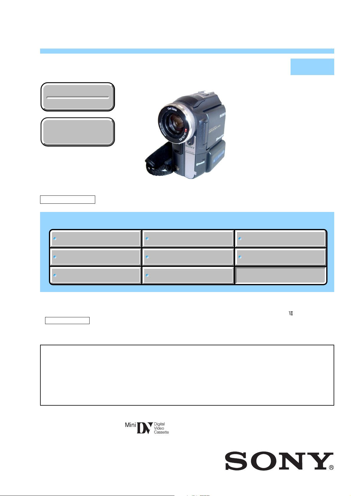
DCR-PC330/PC330E
RMT-831
SERVICE MANUAL
Ver 1.1 2003. 11
Revision History
Revision History
How to use
How to use
Acrobat Reader
Acrobat Reader
Z MECHANISM
Link
Link
SPECIFICATIONS
SPECIFICATIONS
Photo : DCR-PC330
BLOCK DIAGRAMS
BLOCK DIAGRAMS
LEVEL 2
US Model
Canadian Model
Korea Model
DCR-PC330
AEP Model
UK Model
East European Model
Australian Model
Hong Kong Model
Chinese Model
DCR-PC330E
E Model
Tourist Model
DCR-PC330/PC330E
PRINTED WIRING BOARDS
PRINTED WIRING BOARDS
SERVICE NOTE
SERVICE NOTE
DISASSEMBLY
DISASSEMBLY
• For ADJUSTMENTS (SECTION 6), refer to SERVICE MANUAL, ADJ (987627251.pdf).
• For INSTRUCTION MANUAL, refer to SERVICE MANUAL, LEVEL 1 (987627241.pdf).
• For MECHANISM ADJUSTMENTS, refer to the “DV MECHANICAL ADJUSTMENT MANUAL
Z MECHANISM ” (9-876-210-11).
• Reference No. search on printed wiring boards is available.
On the CD-452, VC-325 and BT-021 boards
This service manual provides the information that is premised the circuit board replacement service and not intended repair
inside the CD-452, VC-325 and BT-021 boards.
Therefore, schematic diagram, printed wiring board, waveforms, mounted parts location and electrical parts list of the
VC-325 and BT-021 boards
The following pages are not shown.
Schematic diagram .............................Pages 4-11 to 4-48
Printed wiring board............................Pages 4-75 to 4-82 Electrical parts list ......................... Pages 5-18 to 5-27
Waveforms ...........................................
are not shown.
FRAME SCHEMATIC DIAGRAMS
FRAME SCHEMATIC DIAGRAMS
SCHEMATIC DIAGRAMS
SCHEMATIC DIAGRAMS
Mounted parts location ..................
Page 4-97 to 98
REPAIR PARTS LIST
REPAIR PARTS LIST
Pages 4-101 to 4-103
CD-452,
DIGITAL VIDEO CAMERA RECORDER

DCR-PC330/PC330E
COVER
COVER
SPECIFICATIONS
System
Video recording system
2 rotary heads, Helical scanning system
Sitll image record ing system
Exif Ver. 2.2 *1
*1 “Exif” is a file format for still images,
established by the JEITA (Japan Electronics
and Information Technology Industries
Association). Files in this format can have
additional information such as your
camcorder’s setting inform a tion at the time of
recording.
Audio recording system
Rotary heads, PCM system
Quantization: 12 bi ts (Fs 32 kHz, stereo 1,
stereo 2), 16 bits (Fs 48 kHz, stereo)
Video signal
DCR-PC330: NTSC color, EIA standards
DCR-PC330E: PAL color, CCIR standards
Usable cassette
Mini DV cassette with the mark
printed
Tape speed
SP: Approx. 18.81 mm/s
LP: Approx. 12.56 mm/s
Recording/playback time (using a DVM60
cassette)
SP: 60 min
LP: 90 min
Fast forward/rewind time (using a DVM60
cassette)
Approx. 2 min 40 s
Viewfinder
Electric viewfinder (color)
Image device
5.9 mm (1/3 type) CCD (Charge Coupled
Device)
Gross: Approx. 3 310 000 pixels
Effective (still): Approx. 3 050 000 pi xe ls
Effective (movi e ): Approx. 2 050 000 pixels
Lens
Carl Zeiss Vario-Sonnar T*
Combined power zoom lens
Filter diameter: 37 mm (1 1/2 in.)
10 × (Optical), 120 × (Dig ital)
F = 1.8 ~ 2.1
Focal length
5.1 - 51 mm (7/32 - 2 1/8 in.)
When converted to a 35 mm still camera
In CAMERA-TAPE:
45 - 450 mm (1 13/16 - 17 3/4 in.)
In CAMERA-MEMORY:
37 - 370 mm (1 1/2 - 14 5/8 in.)
Colour temperature
[AUTO], [HOLD], [INDOOR] (3 200 K),
[OUTDOOR] (5 800 K)
Minimum illumination
7 lx (lux) (F 1.8)
0 lx (lux) (during NightShot function)*
*Objects unable to be seen due to the dark can be
shot with infrared lighting.
Input/Output connectors
Audio/Video input/output
10-pin connector
Video signal: 1 Vp-p, 75 Ω (ohms),
unbalanced
Luminance signal: 1 Vp-p, 75Ω (ohms),
unbalanced
Chrominance signal: DCR-PC330: 0.286Vp-p
Audio signal: 327 mV (at output impe da nce
more than 47 kΩ (kilohms)), Input impedance
more than 47 kΩ(kilohms), Output impedance
with less than 2.2 kΩ (kilohms)
DV input/output
4-pin connector
Headphones jack
Stereo minijack (φ 3.5 mm)
LANC jack
Stereo mini-minijack (φ 2.5 mm)
USB jack
mini-B
MIC jack
Minijack, 0.388 mV low impedance wi th DC
2.5 to 3.0 V, output impedance 6.8 kΩ
(kilohms) (φ 3.5 mm), Stereo type
DCR-PC330E: 0.3Vp-p
75Ω (ohms), unbalanced
LCD screen
Picture
6.2 cm (2.5 type)
Total dot number
211 200 (960 × 220)
General
Power requirements
DC 7.2 V (battery pack)
DC 8.4 V (AC Adaptor)
Average power consumption (when using the
battery pack)
During camera recording using the viewfinder
3.3 W
During camera recording using the LCD
3.8 W
Operating temperature
0°C to 40°C (32°F to 104°F)
Storage temperature
-20°C to + 60° C (-4°F to + 140° F)
Dimensions (approx.)
59 × 119 × 113 mm (2 3/8 × 43/4 × 41/2 in.)
(w/h/d)
Mass (Approx.)
540 g (1 lb 3 oz) main unit only
630 g (1 lb 6 oz) including the NP-FM30
rechargeable bat tery pack, DVM60 cassette
and lens cap.
Supplied accessories
See page 4.
AC Adaptor AC-L15A/L15B
Power requirements
AC 100 - 240 V, 50/60 Hz
Current consumption
0.35 - 0.18 A
Power consumption
18 W
Output voltage
DC 8.4 V, 1.5 A
Operating temperature
0°C to 40°C (32°F to 104°F)
Storage temperature
-20°C to + 60° C (-4°F to + 140° F)
Dimensions (approx.)
56 × 31 × 100 mm (2 1/4 × 11/4 × 4 in.) (w/h/
d) excluding the projecting parts
Mass (approx.)
190 g (6.7 oz) excluding the power cord
Rechargeable battery pack (NP-FM30)
Maximum output voltage
DC 8.4 V
Output voltage
DC 7.2 V
Capacity
5.0 Wh (700 mAh)
Dimensions (approx.)
38.2 × 20.5 × 55.6 mm
(1 9/16 × 13/16 × 2 1/4 in.) (w/h/d)
Mass (approx.)
65 g (2.2 oz)
Operating temperature
0°C to 40°C (32° F to 104°F)
Type
Lithium ion
“Memory Stick”
Memory
Flash memory
16MB: MSA-16A
Operating voltage
DC 2.7 - 3.6 V
Power consumption
Approx. 45 mA during operation m ode
Approx. 130 µA during tape recording standby
Dimensions (approx.)
21.5 × 50 × 2.8 mm (7/8 × 2 × 1/8 in.) (w/h/d)
Mass (approx.)
4 g (0.14 oz)
Design and specifications are subject to change
without n o tice.
— 2 —

DCR-PC330/PC330E
SAFETY-RELATED COMPONENT WARNING!!
COMPONENTS IDENTIFIED BY MARK 0 OR DOTTED LINE WITH
MARK 0 ON THE SCHEMATIC DIAGRAMS AND IN THE PARTS
LIST ARE CRITICAL TO SAFE OPERATION. REPLACE THESE
COMPONENTS WITH SONY PARTS WHOSE PART NUMBERS
APPEAR AS SHOWN IN THIS MANUAL OR IN SUPPLEMENTS
PUBLISHED BY SONY.
CAUTION :
Danger of explosion if battery is incorrectly replaced.
Replace only with the same or equivalent type.
SAFETY CHECK-OUT
After correcting the original service problem, perform the following
safety checks before releasing the set to the customer.
1. Check the area of your repair for unsoldered or poorly-soldered
connections. Check the entire board surface for solder splashes
and bridges.
2. Check the interboard wiring to ensure that no wires are
"pinched" or contact high-wattage resistors.
3. Look for unauthorized replacement parts, particularly
transistors, that were installed during a previous repair. Point
them out to the customer and recommend their replacement.
4. Look for parts which, through functioning, show obvious signs
of deterioration. Point them out to the customer and
recommend their replacement.
5. Check the B+ voltage to see it is at the values specified.
6. Flexible Circuit Board Repairing
• Keep the temperature of the soldering iron around 270˚C
during repairing.
• Do not touch the soldering iron on the same conductor of the
circuit board (within 3 times).
• Be careful not to apply force on the conductor when soldering
or unsoldering.
ATTENTION AU COMPOSANT AYANT RAPPORT
À LA SÉCURITÉ!
LES COMPOSANTS IDENTIFÉS PAR UNE MARQUE 0 SUR LES
DIAGRAMMES SCHÉMATIQUES ET LA LISTE DES PIÈCES SONT
CRITIQUES POUR LA SÉCURITÉ DE FONCTIONNEMENT. NE
REMPLACER CES COMPOSANTS QUE PAR DES PIÈSES SONY
DONT LES NUMÉROS SONT DONNÉS DANS CE MANUEL OU
DANS LES SUPPÉMENTS PUBLIÉS PAR SONY.
Unleaded solder
Boards requiring use of unleaded solder are printed with the leadfree mark (LF) indicating the solder contains no lead.
(Caution: Some printed circuit boards may not come printed with
the lead free mark due to their particular size.)
: LEAD FREE MARK
Unleaded solder has the following characteristics.
• Unleaded solder melts at a temperature about 40°C higher than
ordinary solder.
Ordinary soldering irons can be used but the iron tip has to be
applied to the solder joint for a slightly longer time.
Soldering irons using a temperature regulator should be set to
about 350°C.
Caution: The printed pattern (copper foil) may peel away if the
heated tip is applied for too long, so be careful!
• Strong viscosity
Unleaded solder is more viscous (sticky, less prone to flow) than
ordinary solder so use caution not to let solder bridges occur such
as on IC pins, etc.
• Usable with ordinary solder
It is best to use only unleaded solder but unleaded solder may
also be added to ordinary solder.
— 3 —
DCR-PC330/PC330E
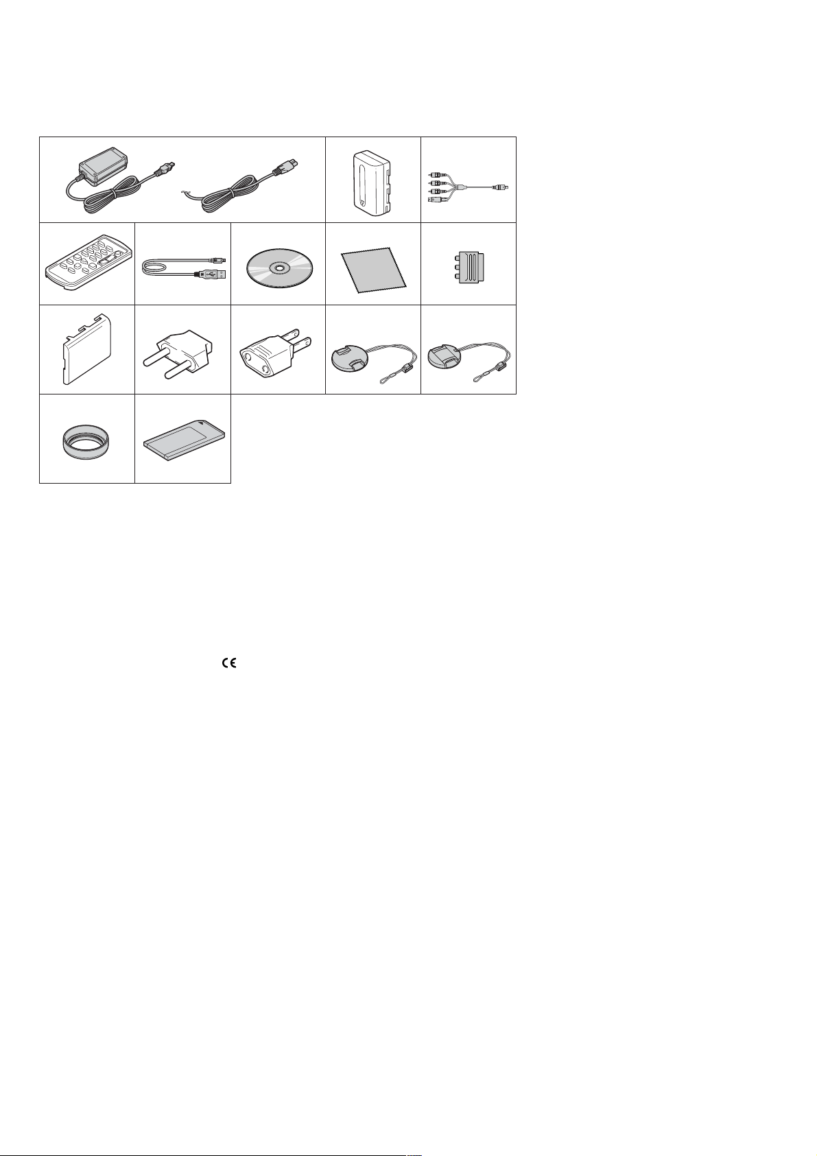
• SUPPLIED ACCESSORIES
Make sure that the following accessories are supplied with your camcorder .
1
4
9
qf
1 AC Adaptor (1), Mains lead (1)
2 NP-FM30 rechargeable battery pack (1)
3 A/V connecting cable (1) (AV multi)(1.5m)
4 Wireless Remote Commander (1)
(RMT-831)
56USB cable (1)
CD-ROM (1)
SPVD-010 USB Driver (DCR-PC330: E, JE, KR/PC330E)
SPVD-010 (I) USB Driver (DCR-PC330: US, CND)
7 Cleaning cloth (1)
8 21-pin adaptor (1) (Models with
printed on their bottom surfaces only)
(PC330E: AEP, UK, EE)
5678
qa qs qd
qg
mark
23
9 Battery terminal cover (1)
q; 2-pin Conversion adaptor (1)
(PC330: JE/PC330E: JE)
qa 2-pin Conversion adaptor (1)
(PC330: E/PC330E: E, HK)
qs Lens cap (Large) (1)
qd Lens cap (Small) (1)
When you use the lens food,
use the small lens cap.
qf Lens hood (1)
qg Memory stick (MSA-16A) (1)
— 4 —

TABLE OF CONTENTS
1. SERVECE NOTE
1-1. SER VICE NOTE ·····························································1-1
1. POWER SUPPLY DURING REPAIRS ··························1-1
2. TO TAKE OUT A CASSETTE WHEN NOT EJECT
(FORCE EJECT) ·····························································1-1
3. HOW TO OPEN THE FLASH WHEN THE FLASH
DOSEN’T OPEN ····························································1-1
4. DISCHARGING OF THE FLASHLIGHT POWER
SUPPLY CAPACITOR ···················································1-2
5. NOTES ON HANDLING THE LASER DIODE
[LASER UNIT (D7609 of FP-706 flexible)] ··················1-3
1-2. SELF-DIAGNOSIS FUNCTION····································1-4
1. SELF-DIAGNOSIS FUNCTION····································1-4
2. SELF-DIAGNOSIS DISPLAY ·······································1-4
3. SELF-DIAGNOSIS CODE TABLE································1-5
2. DISASSEMBLY
2-1. LCD CABINET (R) ASSEMBLY···································2-2
2-2. CABINET (F) SECTION ················································2-3
2-3. CABINET (REAR) SECTION ·······································2-3
2-4. CONTROL SWITCH BLOCK (PS5000) ·······················2-4
2-5. CABINET (R) SECTION ···············································2-4
2-6. TRIPOD SCREW····························································2-5
2-7. BJ-005 BOARD·······························································2-5
2-8. BT-021 BOARD, LITHIUM BATTERY
(SECONDARY) ······························································2-6
2-9. LOUD SPEAKER (1.6CM), FP-704 BOARD, MEMORY
STICK CONNECTOR ···················································· 2-7
2-10. HINGE BLIND ASSEMBLY ··········································2-8
2-11. LCD UNIT ······································································2-8
2-12. PD-198 BOARD······························································2-9
2-13. HINGE ASSEMBL Y····················································· 2-10
2-14. EVF SECTION······························································2-11
2-15. VF-158 BOARD····························································2-12
2-16. STROBOSCOPE SECTION ·········································2-13
2-17. FP-707 BOARD ····························································2-13
2-18. MIC UNIT (MIC5000)·················································· 2-14
2-19. STROBOSCOPE LUMINOUS UNIT (ST5000),
STROBOSCOPE ASSEMBLY ·····································2-14
2-20. LENS SECTION ···························································2-15
2-21. FP-706 BOARD - (1) ····················································2-15
2-22. FP-706 BOARD - (2) ····················································2-16
2-23. CD-452 BOARD, LENS DEVICE LSV-870A ·············2-17
2-24. GMR (M) SENSOR ······················································ 2-17
2-25. IRIS (IR870), STEPPING MOTOR Z870A·················· 2-18
2-26. VC-325 BOARD ···························································2-19
2-27. MECHANISM DECK··················································· 2-19
2-28. AV-081 BOARD ····························································2-20
2-29. JK-257 BOARD ····························································· 2-20
2-30. CONTROL SWITCH BLOCK (FK5000)·····················2-22
2-31. CABINET (L) ASSEMBLY··········································2-22
2-32. CABINET (G) ASSEMBLY ········································· 2-23
2-33. CIRCUIT BOARDS LOCATION ·································2-24
2-34. FLEXIBLE BOARDS LOCATION ······························ 2-25
HELP (List of caution points is shown here.)
3. BLOCK DIAGRAMS
3-1. OVERALL BLOCK DIAGRAM (1/4) ···························3-1
3-2. OVERALL BLOCK DIAGRAM (2/4) ···························3-3
3-3. OVERALL BLOCK DIAGRAM (3/4) ···························3-5
3-4. OVERALL BLOCK DIAGRAM (4/4) ···························3-7
3-5. POWER BLOCK DIAGRAM (1/2)································3-9
3-6. POWER BLOCK DIAGRAM (2/2)······························3-11
4. PRINTED WIRING BOARDS AND
SCHEMATIC DIAGRAMS
4-1. FRAME SCHEMATIC DIAGRAM (1/4) ·······················4-1
DCR-PC330/PC330E
FRAME SCHEMATIC DIAGRAM (2/4)·······················4-3
FRAME SCHEMATIC DIAGRAM (3/4)·······················4-5
FRAME SCHEMATIC DIAGRAM (4/4)·······················4-7
4-2. SCHEMATIC DIAGRAMS
Schematic diagram of the CD-452, VC-325 and
BT-021 board are not shown.
Pages from 4-11 to 4-48 are not shown.
• BJ-005/FP-705 FLEXIBLE (DC/USB/DV JACK,
PANEL SWITCH)
SCHEMATIC DIAGRAM ····························4-49
• PD-198 (RGB DRIVE, BACKLIGHT DRIVE)
SCHEMATIC DIAGRAM ····························4-51
• VF-158 (1/3) (RGB DRIVE, TIMING GENERATOR,
BACK LIGHT)
SCHEMATIC DIAGRAM ····························4-53
• VF-158 (2/3) (MIC AMP)
SCHEMATIC DIAGRAM ····························4-55
• VF-158 (3/3) (CONNECTOR, PITCH/YAW SENSOR
AMP)
SCHEMATIC DIAGRAM ····························4-57
• AV-081/JK-257 (AV MULTI/HP/LANC/MIC JACK)
SCHEMATIC DIAGRAM ····························4-59
• FP-704 FLEXIBLE (MS CONNECTOR)
SCHEMATIC DIAGRAM ····························4-61
• FP-706 FLEXIBLE (REMOCON SENSOR, MF SW)
SCHEMATIC DIAGRAM ····························4-63
• FP-702/FP-707 FLEXIBLE (FLASH DRIVE)
SCHEMATIC DIAGRAM ····························4-65
• FLASH UNIT (ST5000)
SCHEMATIC DIAGRAM ····························4-67
• FP-467/468/228 FLEXIBLE (MD BLOCK)
SCHEMATIC DIAGRAM ····························4-69
• CONTROL SWITCH BLOCK (FK5000)
SCHEMATIC DIAGRAM ····························4-71
• CONTROL SWITCH BLOCK (PS5000)
SCHEMATIC DIAGRAM ····························4-73
4-3. PRINTED WIRING BOARDS
Printed wiring board of the CD-452, VC-325
and BT-021 board are not shown.
Pages from 4-75 to 4-82 are not shown.
• BJ-005 (DC/USB/DV JACK)
PRINTED WIRING BOARD ·······················4-83
• FP-705 FLEXIBLE (PANEL SWITCH)
PRINTED WIRING BOARD ·······················4-85
• PD-198 (RGB DRIVE, BACK LIGHT DRIVE)
PRINTED WIRING BOARD ·······················4-85
• AV-081 (AV MULTI)
PRINTED WIRING BOARD ·······················4-87
• JK-257 (HP/LANC/MIC JACK)
PRINTED WIRING BOARD ·······················4-87
• VF-158 (RGB DRIVE, TIMING GENERATOR, BACK
LIGHT, MIC AMP, CONNECTOR, PITCH/YAW
SENSOR AMP)
PRINTED WIRING BOARD ·······················4-89
• FP-704 FLEXIBLE (MS CONNECTOR)
PRINTED WIRING BOARD ·······················4-91
• FP-707 FLEXIBLE (FLASH DRIVE)
PRINTED WIRING BOARD ·······················4-92
• FP-706 FLEXIBLE (REMOCON SENSOR, MF SW)
PRINTED WIRING BOARD ·······················4-93
• FP-467/468/228 FLEXIBLE (MD BLOCK)
PRINTED WIRING BOARD ·······················4-95
— 5 —

DCR-PC330/PC330E
4-4. WAVEFORMS ······························································4-99
Waveforms of the CD-452 and VC-325 board are not
shown.
Pages 4-97 to 4-98 are not shown.
4-5. MOUNTED PARTS LOCATION ·······························4-104
Mounted parts location of the
CD-452, VC-325
and BT-021 board are not shown.
Page 4-101 to 4-103 is not shown.
5. REPAIR PARTS LIST
5-1-1.OVERALL ······································································5-3
5-1-2.CABINET (R) SECTION-1 ············································5-4
5-1-3.CABINET (R) SECTION-2 ············································5-5
5-1-4.CABINET (L) SECTION-1 ············································5-6
5-1-5.CABINET (L) SECTION-2 ············································5-7
5-1-6.EVF SECTION································································5-8
5-1-7.STROBOSCOPE SECTION ···········································5-9
5-1-8.LENS SECTION ···························································5-10
5-1-9.OVERALL (MECHANISM DECK-Z101) ····················5-11
5-1-10. LS CHASSIS BLOCK ASSEMBLY ··························5-12
5-1-11. MECHANICAL CHASSIS BLOCK ASSEMBLY ····5-13
5-2. ELECTRICAL PARTS LIST ········································5-14
Parts list of the BT-021, CD-452 and VC-325
board are not shown.
Pages from 5-18 to 5-27 are not shown.
— 6 —
DCR-PC330/PC330E
COVER
COVER
SECTION 1
SERVICE NOTE
1-1. SERVICE NOTE
1. POWER SUPPLY DURING REPAIRS
In this unit, about 10 seconds after power is supplied to the battery terminal using the regulated power supply (8.4V), the po wer is shut of f so
that the unit cannot operate.
This following two methods are available to prevent this. Take note of which to use during repairs.
Method 1.
Use the AC power adaptor (AC-L15, AC-VQ800 etc.).
Method 2.
Connect the servicing remote commander RM-95 (J-6082-053-B) to the LANC jack, and set the commander switch to the “ADJ” side.
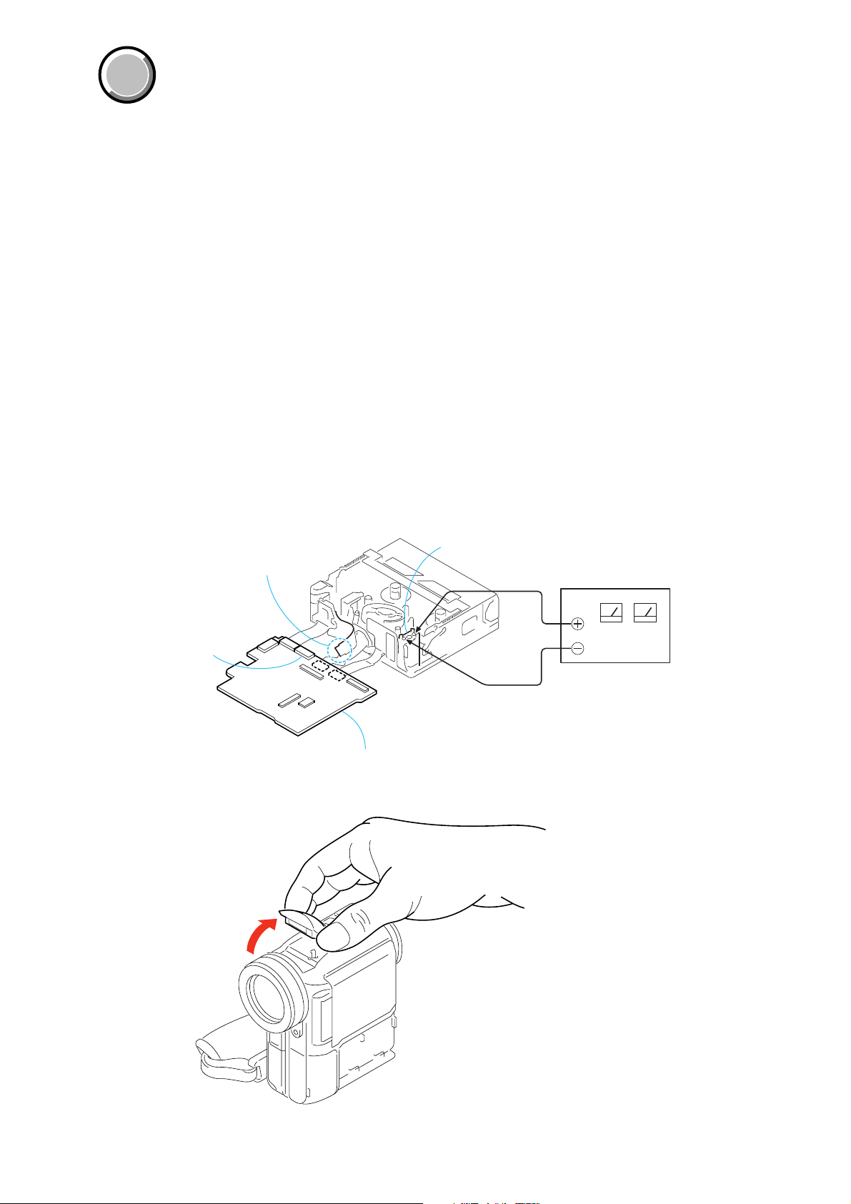
2. TO TAKE OUT A CASSETTE WHEN NOT EJECT (FORCE EJECT)
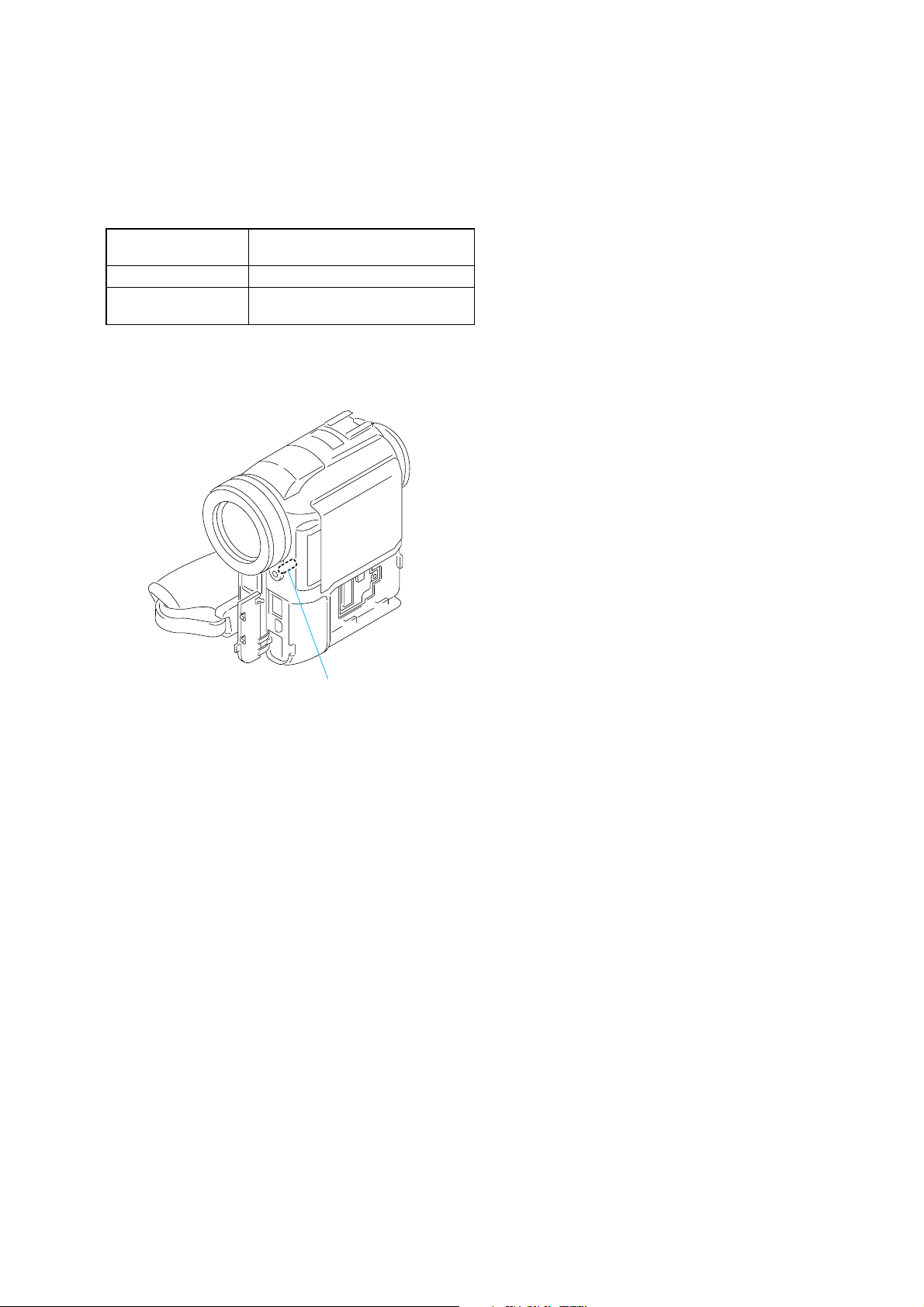
1 Open the flash. (When the flash doesn’t open, refer to “3. HOW TO OPEN THE FLASH WHEN THE FLASH DOSEN’T OPEN”.)
2 Refer to page 2-3 to remove the cabinet (F) section.
3 Refer to page 2-3 to remove the cabinet (Rear) section.
4 Refer to page2-4 to remove the cabinet (R) section.
5 Refer to page2-11 to remove the EVF section.
6 Refer to page2-13 to remove the stroboscope section.
7 Refer to page2-15 to remove the lens section.
8 Open the VC-325 board.
9 Refer to page 2-19 to remove the VC-325 board and the mechanism deck.
q; Disconnect CN2502 (27P, 0.3mm) of VC-325 board.
qa Supply +4.5V from the DC power supply to the loading motor and unload with a pressing the cassette compartment.
Disconnect the flexible board from
CN2502 of VC-325 board.
CN2502
VC-325 board
Loading motor
3. HOW TO OPEN THE FLASH WHEN THE FLASH DOSEN’T OPEN
DC power supply
(+ 4.5Vdc)
1-1
DCR-PC330/PC330E
g
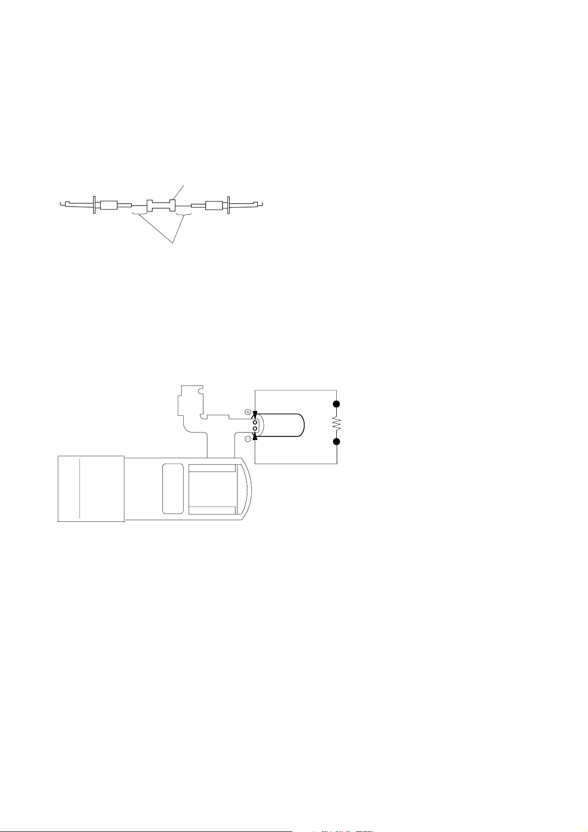
4. DISCHARGING OF THE FLASHLIGHT POWER SUPPLY CAPACITOR
The power supply capacitor (C4208) of the FP-707 flexible is charged up to the maximum 300V potential.
There is a danger of electric shock by this high voltage when the capacitor is handled by hand. The electric shock is caused by the charged
voltage which is kept without discharging when the main power of the unit is simply turned off. Therefore, the remaining voltage must be
discharged as described below.
4-1. PREPARING THE SHORT JIG
To preparing the short jig. a small clip is attached to each end of a resistor of 1kΩ/1W (1-215-869-119)
Wrap insulating tape fully around the reads of the resistor to prevent electric shock.
1 kΩ/1 W
Wrap insulating tape.
4-2. DISCHARGING THE CAPACITOR
1 Open the flash. (When the flash doesn’t open, refer to “3. HOW TO OPEN THE FLASH WHEN THE FLASH DOSEN’T OPEN”.)
2 Refer to page 2-3 to remove the cabinet (F) section.
3 Refer to page 2-3 to remove the cabinet (Rear) section.
4 Refer to page 2-4 to remove the cabinet (R) section.
5 Refer to page 2-11 to remove the EVF section.
6 Refer to page 2-13 to remove the stroboscope section.
7 Remove the insulation sheet of the capacitor (C4208) of the FP-707 flexible.
8 Short-circuit between (+) and (–) terminal of the capacitor (C4208) with the short jig about 10 seconds.
C4208
Short ji
1-2
DCR-PC330/PC330E
5. NOTES ON HANDLING THE LASER DIODE [LASER UNIT (D7609 of FP-706 flexible)]
The laser diode may suffer electrostatic breakdown because of the potential difference generated by the charged electrostatic load, etc. on
clothing and the human body.
During repair, pay attention to electrostatic breakdown and also use the procedure in the printed matter which is inc luded in the repair parts.
The flexible board is easily damaged and should be handled with care.
5-1. Soldering Conditions of Laser Unit (D7609)
Temperature of Less than 350 °C
the Soldering Iron
Time to Solder 3 seconds
Interval to Solder Next terminal is soldered after
waiting for 1 second
Note: Adjustment is needed when laser unit (D7609) is replaced. Refer
to “24. AF Laser Output Adjustment”, “25. AF Laser Axis Check
(1)” and “26. AF Laser Axis Check (2)” of SERVICE MANUAL,
ADJ (987627251.pdf).
Laser Unit (D7609)
1-3
DCR-PC330/PC330E
1-2. SELF-DIAGNOSIS FUNCTION
1. SELF-DIAGNOSIS FUNCTION
When problems occur while the unit is operating, the self-diagnosis
function starts working, and displays on the viewfinder, or LCD
screen what to do. This function consists of two display; selfdiagnosis display and service mode display .
Details of the self-diagnosis functions are provided in the Instruction
manual.
Viewfinder or LCD screen
C : 3 1 : 1 1
Blinks at 3.2Hz
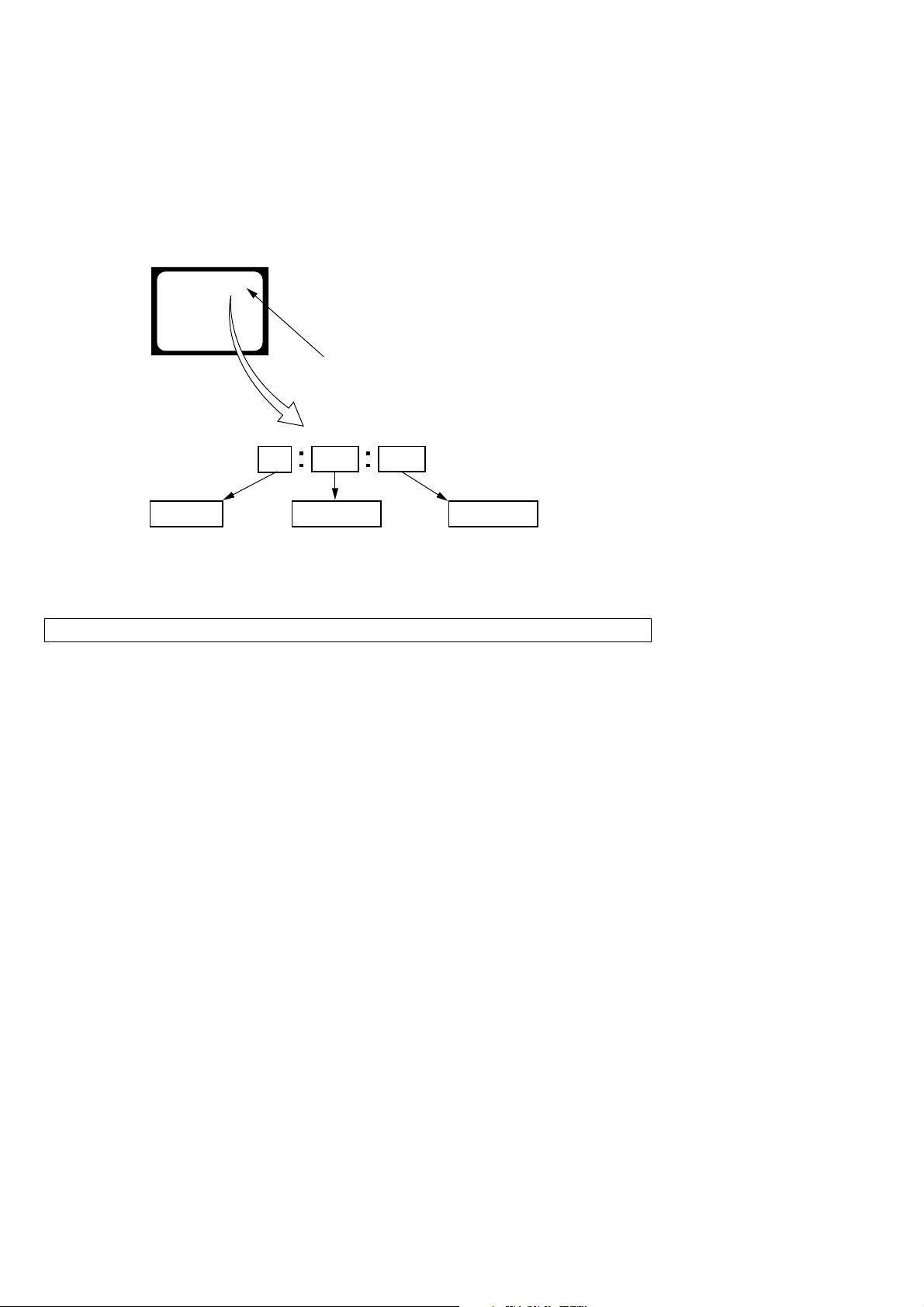
2. SELF-DIAGNOSIS DISPLAY
When problems occur while the unit is operating, the counter of the
viewfinder or LCD screen consists of an alphabet and 4-digit number ,
which blinks at 3.2Hz. This 5-character display indicates the
“repaired by:”, “block” in which the problem occurred, and “detailed
code” of the problem.
3 1C
Repaired by:
C : Corrected by customer
H : Corrected by dealer
E : Corrected by service
engineer
Note: The self-diagnosis display data will be kept even if the lithium battery (BT9901 of BT-021 board) is removed.
Indicates the appropriate
step to be taken.
E.g.
31 ....Reload the tape.
32 ....Turn on power again.
Block
1 1
Detailed Code
Refer to page 1-5.
Self-diagnosis Code Table.
1-4
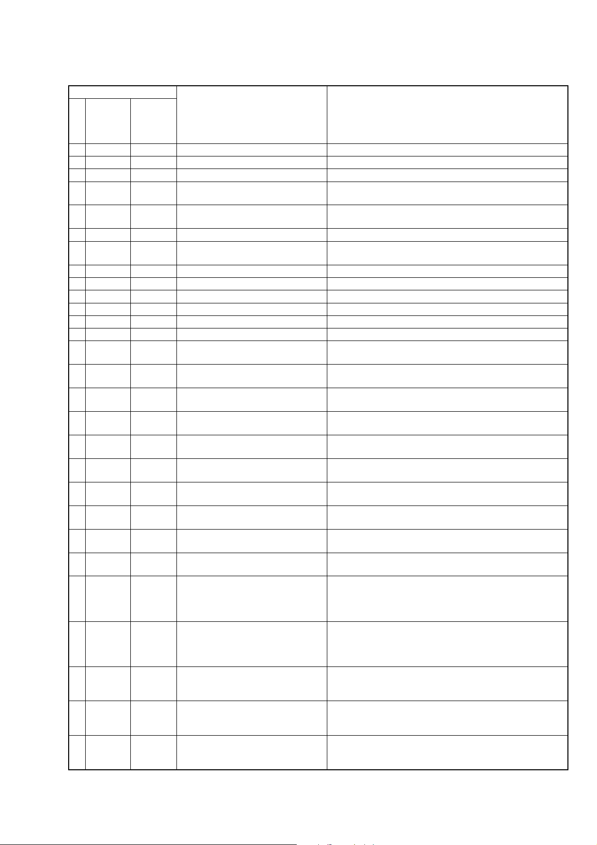
3. SELF-DIAGNOSIS CODE TABLE
Self-diagnosis Code
DCR-PC330/PC330E
Ver 1.1 2003. 11
Function
Repaired by:
C
C
C
C
C
C
C
C
C
C
C
C
C
C
C
C
C
C
C
C
C
C
C
E
E
E
E
E
Block
04
21
22
31
31
31
31
31
31
31
31
31
31
32
32
32
32
32
32
32
32
32
32
61
61
62
62
91
Detailed
Code
00
00
00
10
11
20
21
22
23
24
30
40
42
10
11
20
21
22
23
24
30
40
42
00
10
00
01
01
Symptom/State
Non-standard battery is used.
Condensation.
Video head is dirty.
LOAD direction. Loading does not
complete within specified time
UNLOAD direction. Loading does not
complete within specified time
T reel side tape slacking when unloading
Winding S reel fault when counting the
rest of tape.
T reel fault.
S reel fault.
T reel fault.
FG fault when starting capstan.
FG fault when starting drum.
FG fault during normal drum operations.
LOAD direction loading motor time-
out.
UNLOAD direction loading motor
time-out.
T reel side tape slacking when
unloading.
Winding S reel fault when counting the
rest of tape.
T reel fault.
S reel fault.
T reel fault.
FG fault when starting capstan.
FG fault when starting drum
FG fault during normal drum
operations
Difficult to adjust focus
(Cannot initialize focus.)
Zoom operations fault
(Cannot initialize zoom lens.)
Steadyshot function does not work well.
(With pitch angular velocity sensor output
stopped.)
Steadyshot function does not work well.
(With yaw angular v elocity sensor output
stopped.)
Abnormality when the power supply
capacitor of the flash unit is being
charged.
Correction
Use the info LITHIUM battery.
Remove the cassette, and insert it again after one hour.
Clean with the optional cleaning cassette.
Load the tape again, and perform operations from the beginning.
Load the tape again, and perform operations from the beginning.
.
Load the tape again, and perform operations from the beginning.
Load the tape again, and perform operations from the beginning.
Load the tape again, and perform operations from the beginning.
Load the tape again, and perform operations from the beginning.
Load the tape again, and perform operations from the beginning.
Load the tape again, and perform operations from the beginning.
Load the tape again, and perform operations from the beginning.
Load the tape again, and perform operations from the beginning.
Remove the battery or power cable, connect, and perform
operations from the beginning.
Remove the battery or power cable, connect, and perform
operations from the beginning.
Remove the battery or power cable, connect, and perform
operations from the beginning.
Remove the battery or power cable, connect, and perform
operations from the beginning.
Remove the battery or power cable, connect, and perform
operations from the beginning.
Remove the battery or power cable, connect, and perform
operations from the beginning.
Remove the battery or power cable, connect, and perform
operations from the beginning.
Remove the battery or power cable, connect, and perform
operations from the beginning.
Remove the battery or power cable, connect, and perform
operations from the beginning.
Remove the battery or power cable, connect, and perform
operations from the beginning.
Inspect the lens block focus MR sensor (Pin ql, wa of CN1301 of
VC-325 board) when focusing is performed when the focus ring is
rotated in the focus manual mode, and the focus motor drive circuit
(IC1303 of VC-325 board) when the focusing is not performed.
Inspect the lens block zoom MR sensor (
VC-325 board
is operated and the zoom motor drive circuit (IC1303 of VC-325
board) when zooming is not performed.
Inspect pitch angular velocity sensor (SE3502 of VF-158 board)
peripheral circuits.
Inspect yaw angular velocity sensor (SE3501 of VF-158 board)
peripheral circuits.
Checking or replacement of the flash unit.
) when zooming is performed when the zoom switch
Pin qh, qj of CN1301 of
1-5E
DCR-PC330/PC330E
DISASSEMBLY
HELP
DISASSEMBLY
HELP
DISASSEMBLY
DISASSEMBLY
DISASSEMBLY
DISASSEMBLY
DISASSEMBLY
DISASSEMBLY
DISASSEMBLY
DISASSEMBLY
DISASSEMBLY
DISASSEMBLY
DISASSEMBLY
HELP
HELP
DISASSEMBLY
SERVICE POSITION TO
CHECK THE VTR SECTION
PD-198 board
service position
Discharging the Capacitor
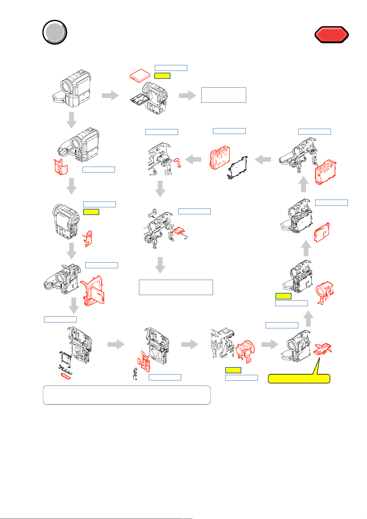
PROCEDURE OF REMOVING THE MECHANISM DECK. (VTR CHECK SERVICE POSITION)
1 2-2. CABINET (F) SECTION ...................................
2 2-3. CABINET (REAR) SECTION ...........................
3 2-5. CABINET (R) SECTION ..................................
4 2-6. TRIPOD SCREW .............................................
5 2-7. BJ-005 BOARD ................................................
6 2-14. EVF SECTION ...............................................
7 2-16. STROBOSCOPE SECTION ..........................
8 2-20. LENS SECTION ............................................
9 2-21. FP-706 BOARD - (1) .....................................
0 2-26. VC-325 BOARD .............................................
(page 2-3)
(page 2-3)
(page 2-4)
(page 2-5)
(page 2-5)
(page 2-11)
(page 2-13)
(page 2-15)
(page 2-15)
(page 2-19)
qa 2-27. MECHANISM DECK ....................................
qs 2-28. AV-081 BOARD ............................................
qd 2-29. JK-257 BOARD ............................................
qf SERVICE POSITION TO CHECK
THE VTR SECTION..............................................
(page 2-19)
(page 2-20)
(page 2-20)
(page 2-21)
COVER
COVER
SECTION 2
DISASSEMBLY
The following flow chart shows the disassembly procedure.
HELP
HELP
2-1
DCR-PC330/PC330E
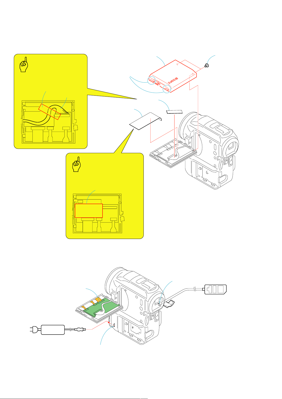
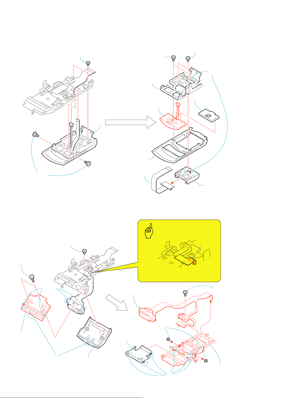
2-1. LCD CABINET (R) ASSEMBLY
Caution
Attach the tape (A) as shown
in the illustration.
Tape (A)
Harness (PB-053)
PD-198
3
LCD cabinet (R) assembly
2
Two claws
4
5
Sheet (panel)
Tape (A)
1
Two MI screws
(M1.7 × 2.5)
Caution
Attach the sheet (panel)
as shown in the illustration.
[PD-198 BOARD SERVICE POSITION]
PD-198 board
Sheet (panel)
PD-198
PD-
198
LANC jack
Adjustment remote
commander (RM-95)
AC IN
AC power
adaptor
PD-
198
DC IN connector
2-2
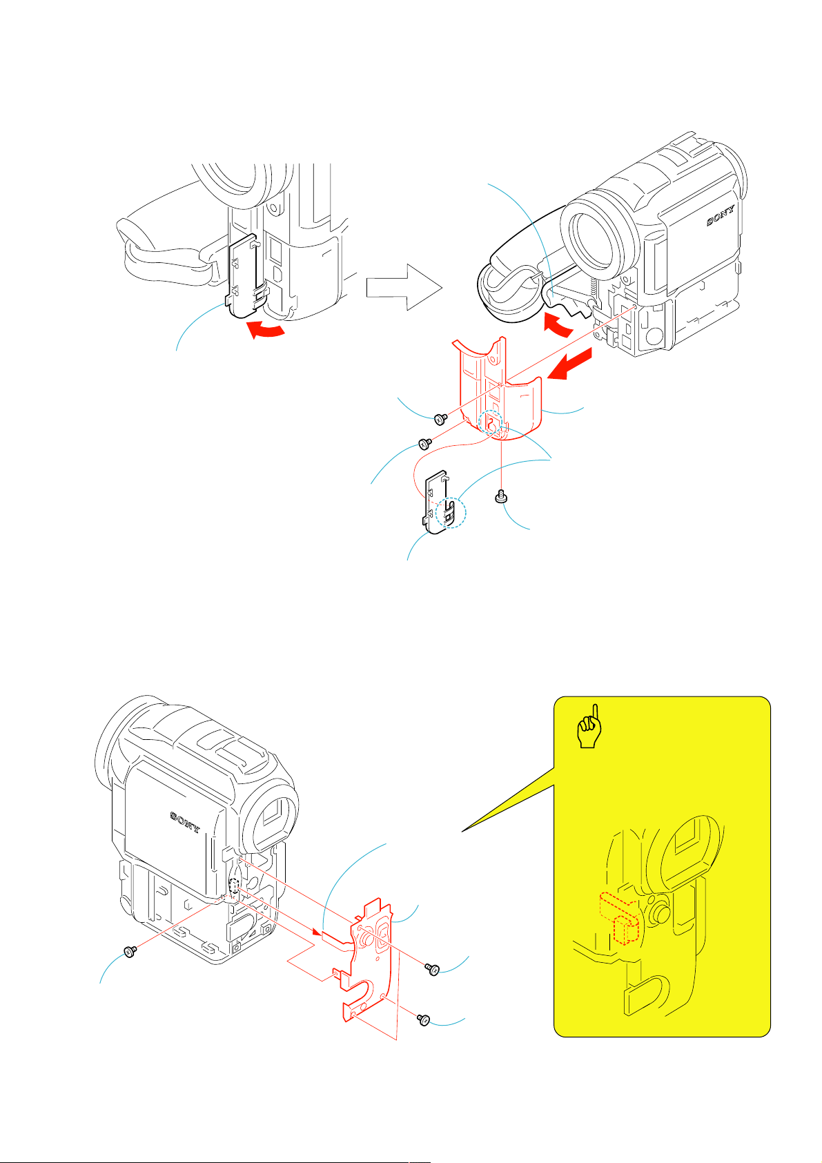
2-2. CABINET (F) SECTION
1
Open the jack cover (F) assembly.
2
Tapping screw
(TP1.7
×
3.5) (black)
3
Open the
cassette lid.
DCR-PC330/PC330E
6
9
Cabinet (F) section
4
Screw (M1.7 × 2.5),
lock ace, p2 (black)
2-3. CABINET (REAR) SECTION
8
Jack cover (F) assembly.
4
Control switch block
(PS5000) (14P)
7
Claw
5
Screw (M1.7 × 2.5),
lock ace, p2 (black)
Caution
When install the cabinet (rear) section to
the main body, install the flexible board of
control switch block (PS5000) as shown
in the illustration.
1
Screw (M1.7 × 2.5),
lock ace, p2 (black)
5
Cabinet (rear) section
2
Two screws
(M1.7
lock ace, p2
3
Screw
(M1.7
lock ace, p2
(black)
2-3
×
4),
×
2.5),
DCR-PC330/PC330E
2-4. CONTROL SWITCH BLOCK (PS5000)
3
Control switch block
(PS5000)
1
Two tapping screws
(M1.7
×
3.5) (black)
2
Cabinet (rear) assembly
2-5. CABINET (R) SECTION
7
Open the
stroboscope.
9
Open the cassette lid.
qa
Caution
Be careful not to drop it.
qg
Compression spring
qf
Battery
lock knob
8
Screw (M1.7 × 2.5),
lock ace, p2 (black)
qs
FP-704 flexible board (15P)
4
Screw (M1.7 × 2.5),
lock ace, p2 (black)
Caution
If the Cabinet (R) section is removed
with extra force, the FP-704 flexible
board and the BJ-005 board can be
damaged. Be careful not to damage
them.
q;
BJ-005 board (80P)
6
Screw (M1.7 × 2.5),
lock ace, p2 (black)
qd
Cabinet (R) section
2-4
5
Screw (M1.7 × 2.5),
lock ace, p2 (black)
1
Screw (M1.7 × 2.5),
lock ace, p2 (black)
3
CPC lid
2
Claw
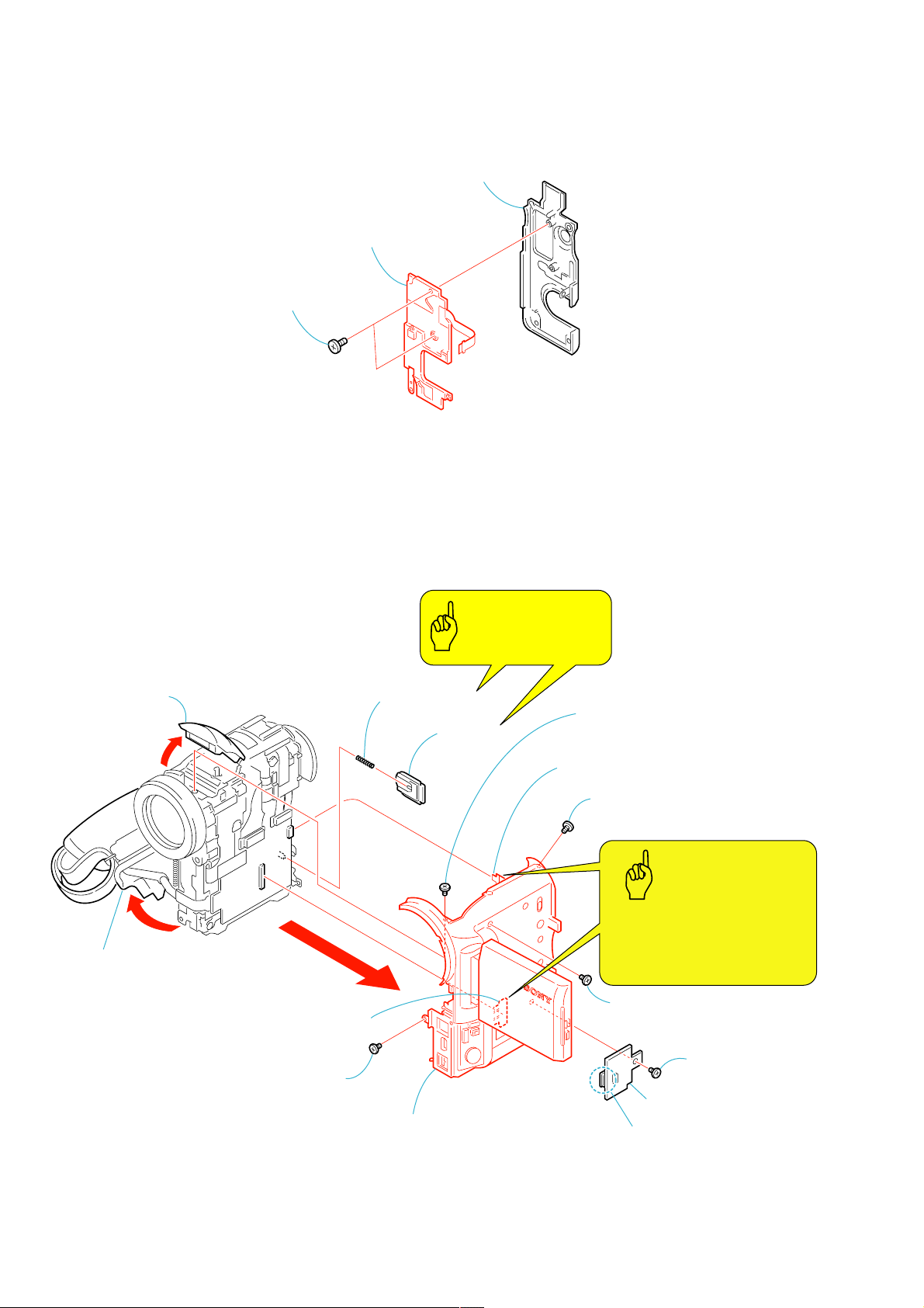
2-6. TRIPOD SCREW
w
1
FP-705 flexible
board (6P)
2
Harness
(PB-053) (20P)
3
Tapping screw
(M1.7
×
3.5)
(silver)
4
Jack retainer DC
5
FP-703 flexible
board (15P)
6
BJ-005 board
2
Two tapping screws
(M1.7
×
4
BT terminal retainer
3.5) (silver)
DCR-PC330/PC330E
1
Cla
6
Bottom frame assembly
2-7. BJ-005 BOARD
7
Tripod screw
3
Three screws
(M1.7
lock ace, p2
5
Tapping screw
(TP1.7
×
5),
×
3.5) (silver)
2-5
DCR-PC330/PC330E
2-8. BT-021 BOARD, LITHIUM BATTERY (SECONDARY)
3
FP-703 flexible
board (15P)
4
BT-021 board
2
BT-021 board,
FP-703 flexible board
1
Screw (M1.7 × 2.5),
lock ace, p2 (silver)
5
Two soldering
6
Lithium battery
2-6
DCR-PC330/PC330E
2-9. LOUD SPEAKER (1.6CM), FP-704 BOARD, MEMORY STICK CONNECTOR
Caution
When re-assembling, align
the switch position beforehand.
9
LCD back light knob
8
Memory stick connector,
Loud speaker (1.6cm),
6
Speaker retainer
assembly
4
Screw
(TP1.7
5
Two tapping
screw
(TP1.7
(silver)
×
3.5)
×
2.5)
FP-704 board
7
Screw
(TP1.7
(silver)
×
2.5)
q;
Indication
selection
switch
2
Tapping screw
(TP1.7
(silver)
1
(TP1.7
(silver)
×
3.5)
Tapping screw
×
5)
3
BB retainer
qs
Loud speaker (1.6cm)
qa
Remove the
two solderings
qf
Memory stick connector
2-7
qd
FP-704 board (15P)
DCR-PC330/PC330E
2-10.HINGE BLIND ASSEMBLY
2
Open the LCD panel.
3
Two screws (M1.7 × 2.5),
lock ace, p2 (silver)
1
Screw
(M1.7 × 2.5)
Caution
When re-assembling, pass the harness (PB-053)
through the groove the hinge blind assembly.
The harness must
be hooked here.
Harness (PB-053)
2-11.LCD UNIT
Caution
When re-assembling,
attach the tape (A) as shown.
Groove
3
LCD cabinet (R) assembly
2
Two claws
4
Hinge blind assembly
1
Two MI screws
(M1.7 × 2.5)
5
(PB-053) (20P)
Harness
A
Tape (A)
Harness (PB-053)
PD-198
4
Tape (A)
7
LCD unit
2-8
PD-
198
A
6
Two screws
(M1.7 × 2.5),
lock ace, p2 (black)
2-12.PD-198 BOARD
PD-
198
(6P)
(24P)
PD-198
1
Sheet (panel)
Sheet (panel)
2
Two screws
(M1.7
×
2.5),
lock ace, p2
(silver)
3
LCD cabinet (L) assembly
4
Panel protection sheet
5
Liquid crystal
indicator module
8
Back light (6P)
Cold cathode
fluorescent tube
6
Screw
(M1.7
×
2.5),
lock ace, p2
(silver)
7
Two claws
9
PD-198 board
Caution
When re-assembling, attach
the sheet (panel) as shown.
DCR-PC330/PC330E
2-9
DCR-PC330/PC330E
2-13.HINGE ASSEMBLY
A
1
Rotate the hinge in the
direction of the arrow
8
FP-705 flexible board
A
2
.
Two tapping screws
×
(M1.7
7
Claw
3.5) (silver)
3
6
Claw
9
Hinge cover (rear)
5
Screw (grip)
(M1.7
qs
Harness (PB-053)
×
2.5) (black)
4
Tape (A)
qa
Hinge cover (front)
q;
Claw
qd
2-10
Hinge assembly
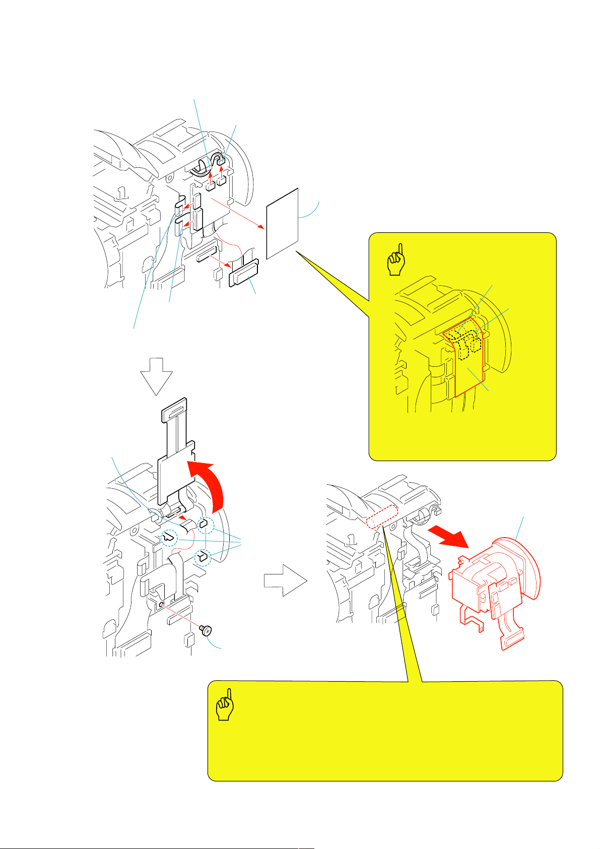
2-14.EVF SECTION
8
2
FP-700 flexible
board (23P)
9
FP-702 flexible
board (16P)
1
VF-158 board (60P)
3
Control switch block
(FK5000) (8P)
4
VF protection sheet
VF protection
sheet
Caution
7
Three claws
qa
EVF section
Caution
The power capacitor of the flash unit is charged up to 300 V maximum. If you touch
the capacitor terminal that is charged to high voltage, you will receive an electric
shock. This high voltage is not discharged even if you turned off the main power
of this set, and it residues. Discharge the residual voltage referring to the service
note (page 1-2).
q;
Screw (M1.7 × 2.5),
lock ace, p2 (silver)
5
FP-701 flexible
board (10P)
FP-701
flexible board
Attach the VF protection sheet in the way
that the PF-701 flexible board is positioned
in the right angle with the harness (MIC unit).
6
MIC unit (MIC5000) (4P)
Harness
(MIC unit)
DCR-PC330/PC330E
2-11
DCR-PC330/PC330E
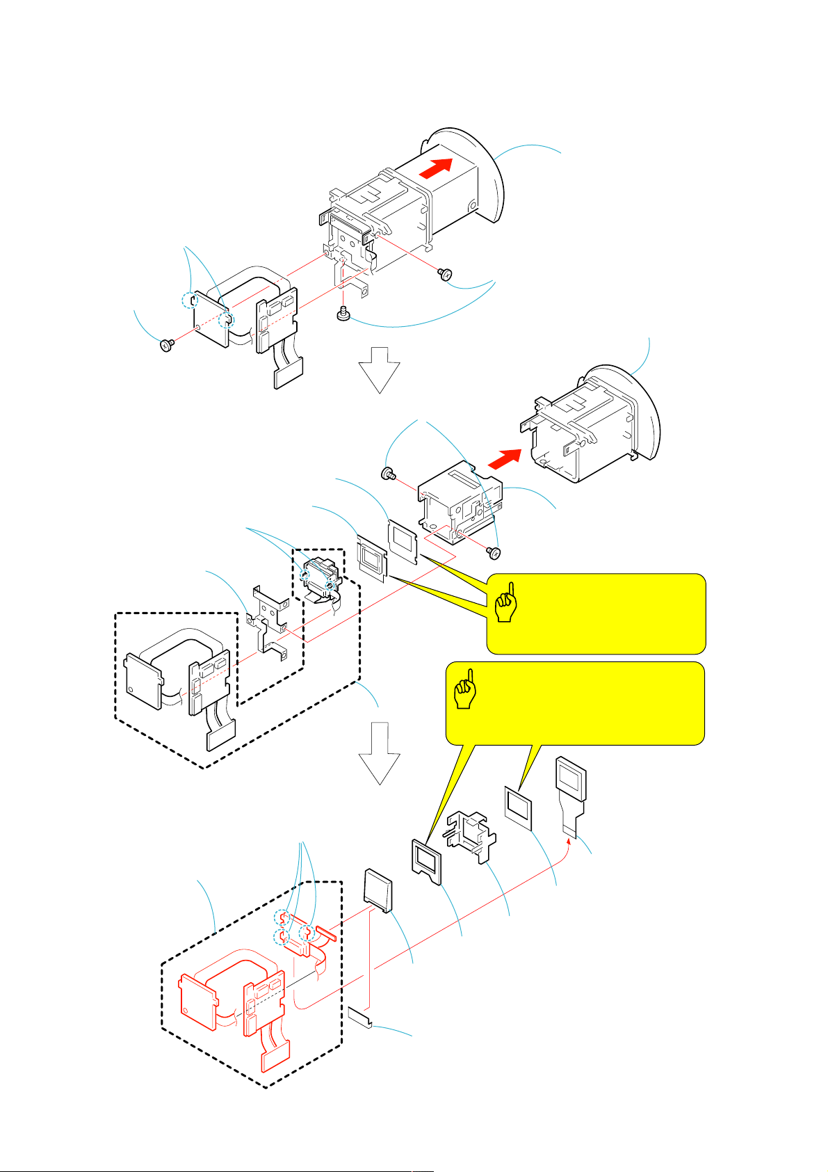
2-15.VF-158 BOARD
2
1
Screw (M1.7 × 2.5),
lock ace, p2 (silver)
Two claws
4
lock ace, p2 (silver)
6
Two screws
(M1.7 × 2.5),
lock ace, p2 (silver)
3
Slide the Finder in the
direction of the arrow.
Two screws (M1.7 × 2.5),
5
VF lens assembly,
VF regulation ring assembly
7
VF PC board fixed plate
q;
LCD cushion (044)
8
Two claws
w;
VF-158 board
qa
VF light sheet
qg
Three claws
qs
9
Sleeve guide assembly
Caution
Be careful not to drop the LCD
cushion (044) and VF light sheet.
Caution
Be careful not to drop the LCD cushion (2)
and BL cushion (B)
qd
LCX033AN-1
(16P)
qf
LCD cushion (2)
2-12
qh
Back light holder
qj
BL cushion (B)
ql
Light guide plate block (0.44)
qk
BL retainer sheet metal
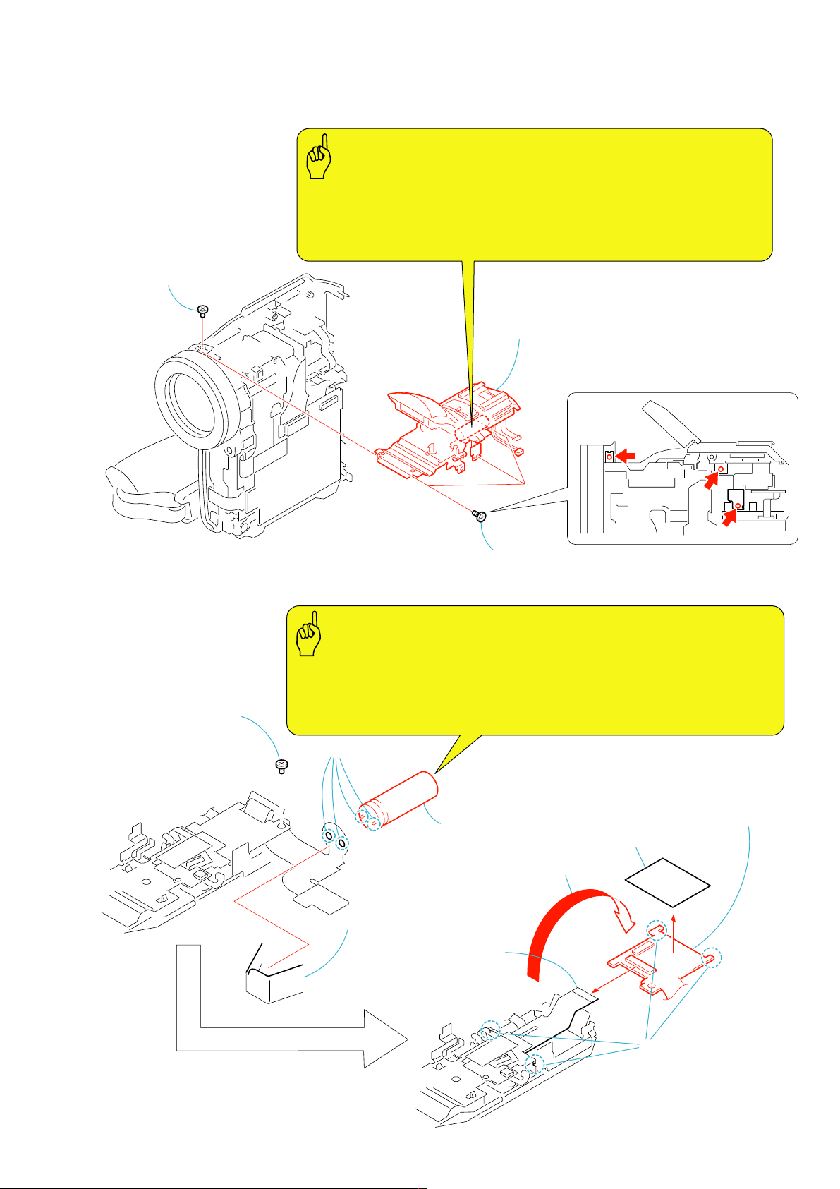
2-16.STROBOSCOPE SECTION
d
1
Screw (M1.7 × 2.5),
lock ace, p2 (black)
DCR-PC330/PC330E
Caution
The power capacitor of the flash unit is charged up to 300 V maximum. If you touch
the capacitor terminal that is charged to high voltage, you will receive an electric
shock. This high voltage is not discharged even if you turned off the main power
of this set, and it residues. Discharge the residual voltage referring to the service
note (page 1-2).
3
Stroboscope section
2-17.FP-707 BOARD
4
Screw (M1.7 × 2.5),
lock ace, p2 (silver)
2
Three tapping screws
(M1.7 × 3.5) (silver)
Caution
The power capacitor of the flash unit is charged up to 300 V maximum. If you touch
the capacitor terminal that is charged to high voltage, you will receive an electric
shock. This high voltage is not discharged even if you turned off the main power
of this set, and it residues. Discharge the residual voltage referring to the service
note (page 1-2).
2
Remove the
two solderings
9
3
Elect 80MF cap
1
Condenser insulating sheet
7
Stroboscope luminous
unit (ST5000) (24P)
6
Make the FP-707
board inside-out.
8
ST insulating sheet
FP-707
FP-707 boar
2-13
5
Two claws
DCR-PC330/PC330E
r
e
2-18.MIC UNIT (MIC5000)
2
Two screws
(M1.7
lock ace, p2 (silver)
×
2.5),
3
4
Two tapping screws
(M1.7
7
×
3.5) (silver)
Hot shoe frame
qs
MIC unit
(MIC5000)
5
Two screws
(M1.7
qa
Microphone
cushion
×
2.5) (silver)
6
Claw
q;
Cabinet (upper)
8
FP-701 flexible
1
Two screws
(M1.7
×
1.8)
board (10P)
9
External connecto
(hot shoe)
2-19.STROBOSCOPE LUMINOUS UNIT (ST5000), STROBOSCOPE ASSEMBLY
Caution
6
Screw (M1.7 × 2.5),
lock ace, p2 (silver)
1
Two tapping screws
×
(M1.7
5) (black)
4
claws
Two
When re-assembling,
confirm the switch position.
8
Stroboscope luminous
unit (ST5000)
switch
7
Screw (bolt)
(M1.4
×
3)
5
Unit cover
assembly
2
Claw
3
Stroboscope
cabinet
qa
(stroboscope)
q;
Blind cabinet
2-14
Two cushions
9
Three claws
qs
Stroboscop
assembly
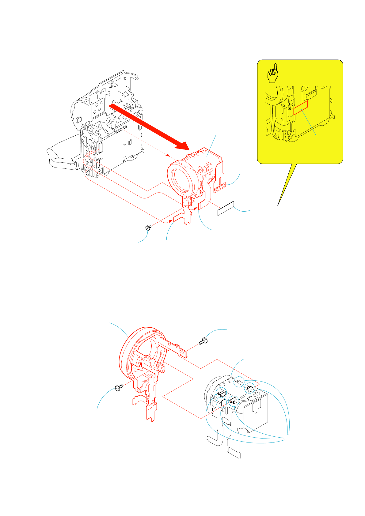
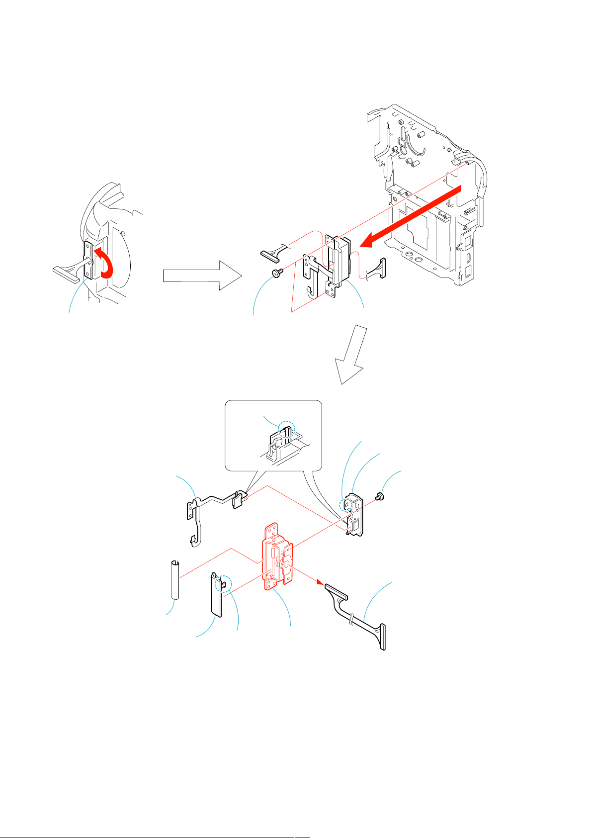
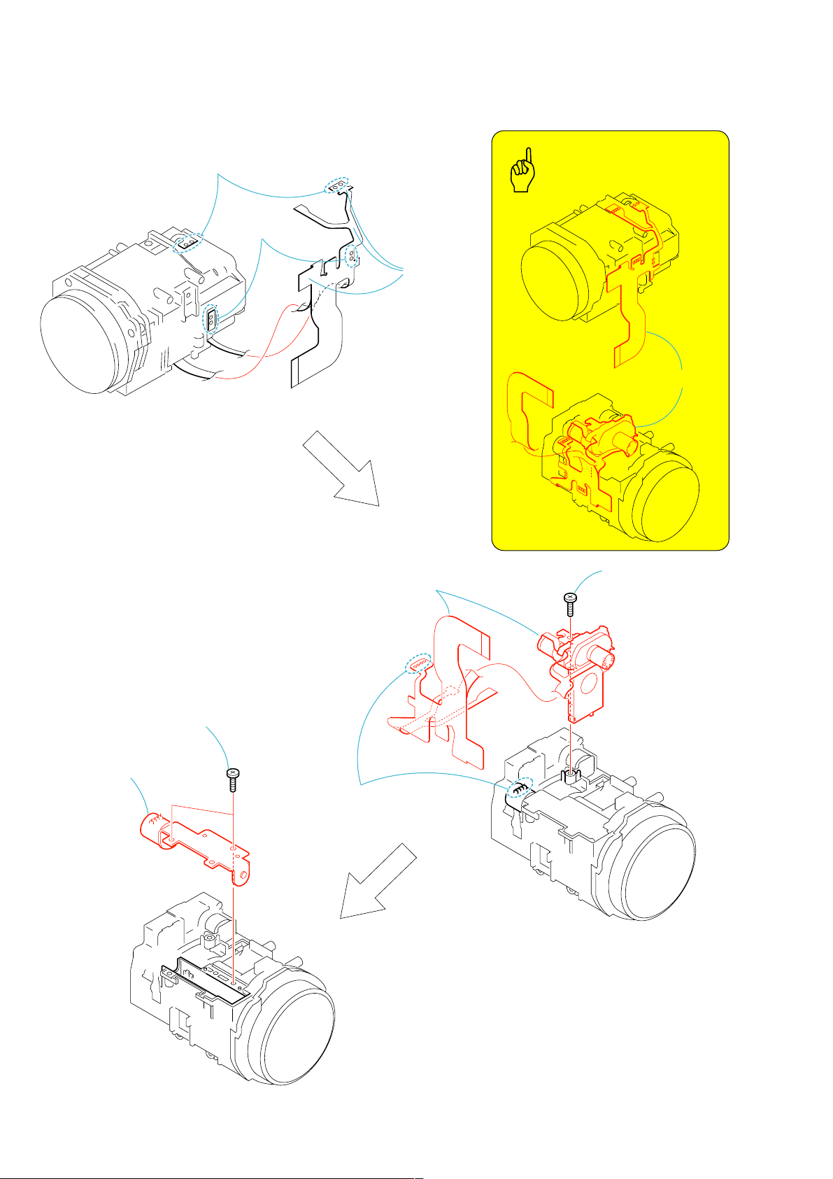
2-20.LENS SECTION
VC325
1
CD-452 board
(80P)
4
FP-706 board (18P)
2
Tape (A)
Tape (A)
3
Flexible board
(from lens device)(33P)
5
Screw
(M1.7 × 2.5),
lock ace, p2(silver)
6
Lens section
Caution
When re-assembling,
attach the tape (A) as shown.
d
DCR-PC330/PC330E
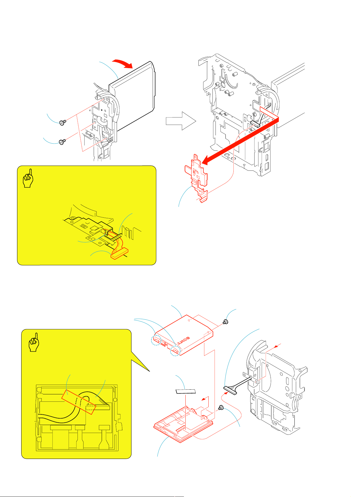
2-21.FP-706 BOARD - (1)
5
MF ring assembly,
FP-706 board
2
Tapping screw
(M1.7
×
5) (silver)
1
Tapping screw
(M1.7
×
5) (silver)
4
Lens device LSV-870A,
CD-452 board, etc.
3
Remove the
four dowels an
convex part
2-15
DCR-PC330/PC330E
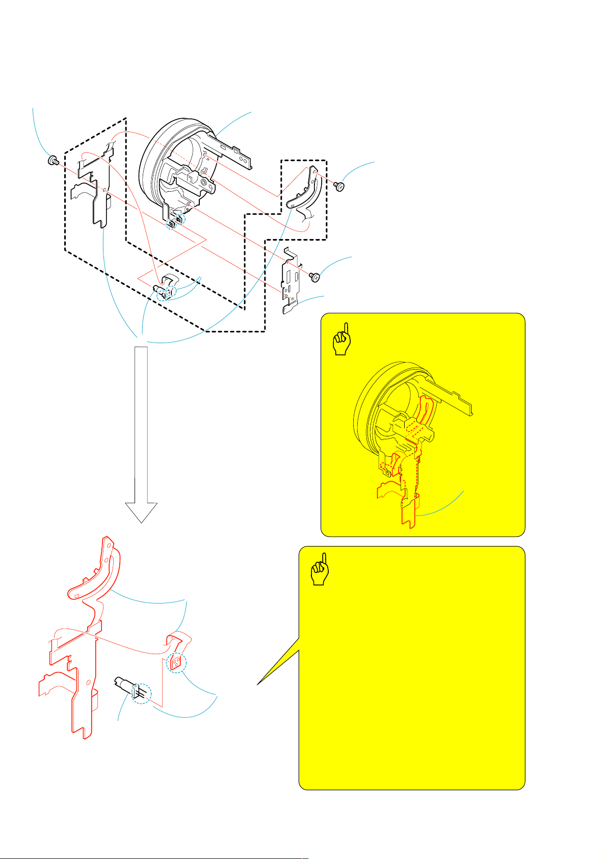
2-22.FP-706 BOARD - (2)
2
Screw (M1.7 × 2.5),
lock ace, p2 (silver)
1
Two
claws
6
MF ring assembly
4
IR frame
5
Screw (M1.7 × 2.5),
lock ace, p2 (silver)
3
Tapping screw
×
(M1.7
3.5) (silver)
7
q;
FP-706 board
Caution
FP-706 board
Caution
When soldering the laser unit on the FP-706 board,
observe the following things.
(Refer to Service Note (page 1-3)).
Observe the following conditions of temperature
and time of soldering.
Temperature of soldering iron : 350
Time of contacting the soldering : 3 seconds
iron with the solder
°
9
Laser unit
8
Three solderings
The laser diode may suffer electrostatic breakdown
because of the potential difference generated by the
charged electrostatic load, etc. on clothing and the
human body.
During repair, pay attention to electrostatic breakdown
and also use the procedure in the printed matter which
is included in the repair parts.
The flexible board is easily damaged and should be
handled with care.
2-16
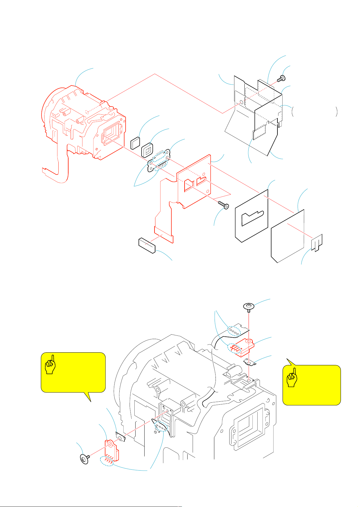
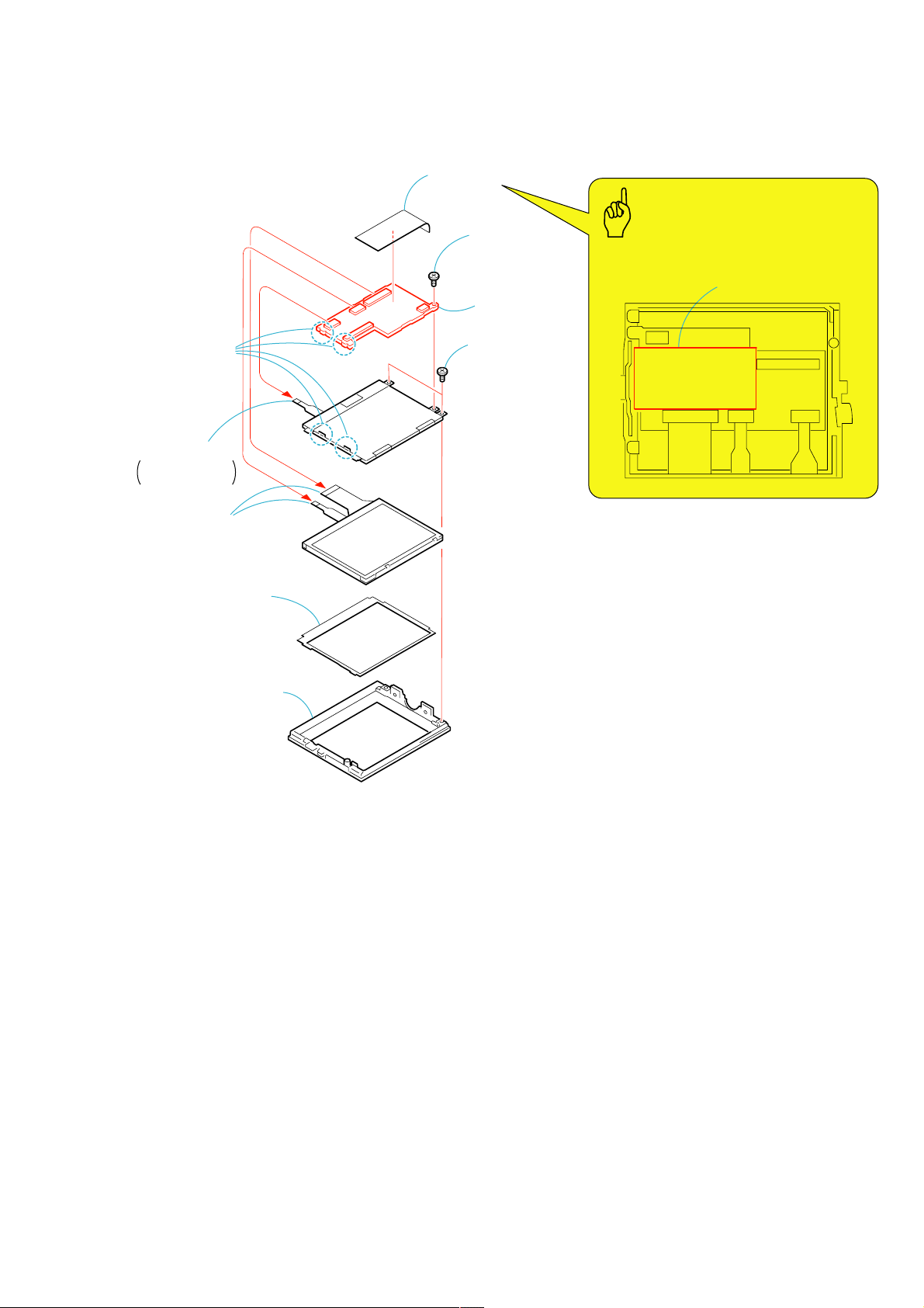
2-23.CD-452 BOARD, LENS DEVICE LSV-870A
1
FK flexible
fixed sheet
2
CD shield
sheet (A)
3
Tapping screw
(M1.7
×
5) (silver)
4
CD heat sink,
CD radiation sheet,
MD flexible guard sheet, etc.
(CD heat sink)
(CD radiation sheet)
(CD radiation sheet (small))
(MD flexible guard sheet)
5
CDF sheet
6
BB retainer cushion (A)
7
Two tapping screws
(M1.7
×
5) (silver)
8
Lens device LSV-870A
9
Optical filter block
(OFB-04-30)
q;
Seal rubber (870)
qa
Remove the
solderings
qs
CCD block
assembly
qd
CD-452
board
CD radiation sheet
(L)(large)
1
Screw (M1.4 × 3.5)
5
Screw
(M1.4 × 3.5)
4
GMR (M) sensor
8
GMR (M) sensor
2
MR spacer (760)
6
MR spacer (760)
3
Remove the
four solderings
7
Remove the
four solderings
Be careful not to drop
the MR spacer (760).
Be careful not to drop
the MR spacer (760).
Caution
Caution
DCR-PC330/PC330E
2-24.GMR (M) SENSOR
2-17
DCR-PC330/PC330E
2-25.IRIS (IR870), STEPPING MOTOR Z870A
1
Remove the
two solderings
2
Remove the
two solderings
3
Peel off the
adhesion
part.
Caution
Iris (IR870)
7
(B1.7
8
Stepping motor
Z870A
Two tapping screws
×
5) (black)
6
Iris (IR870)
4
Remove the
four solderings
5
Tapping screw
×
(B1.7
5) (black)
2-18
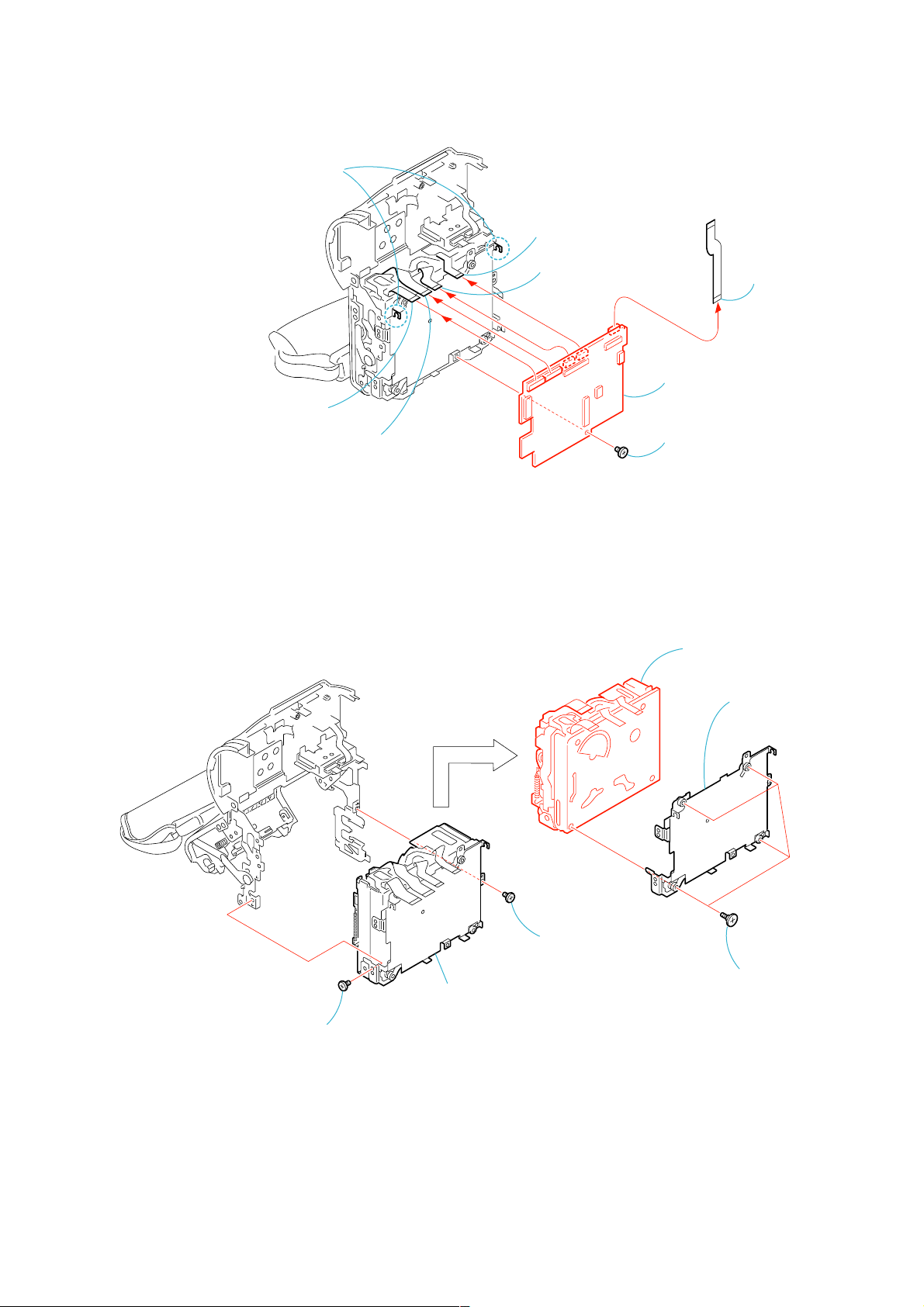
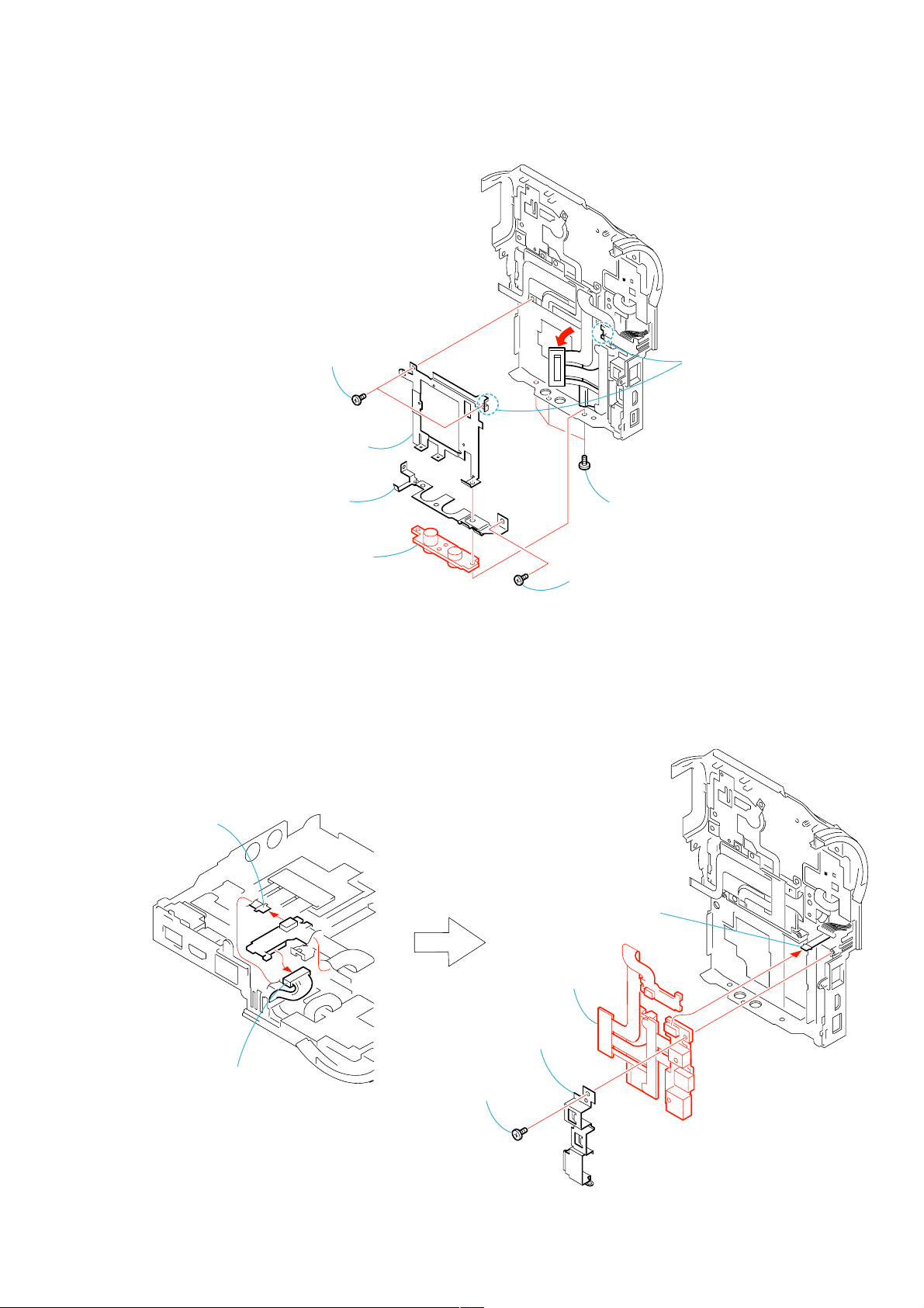
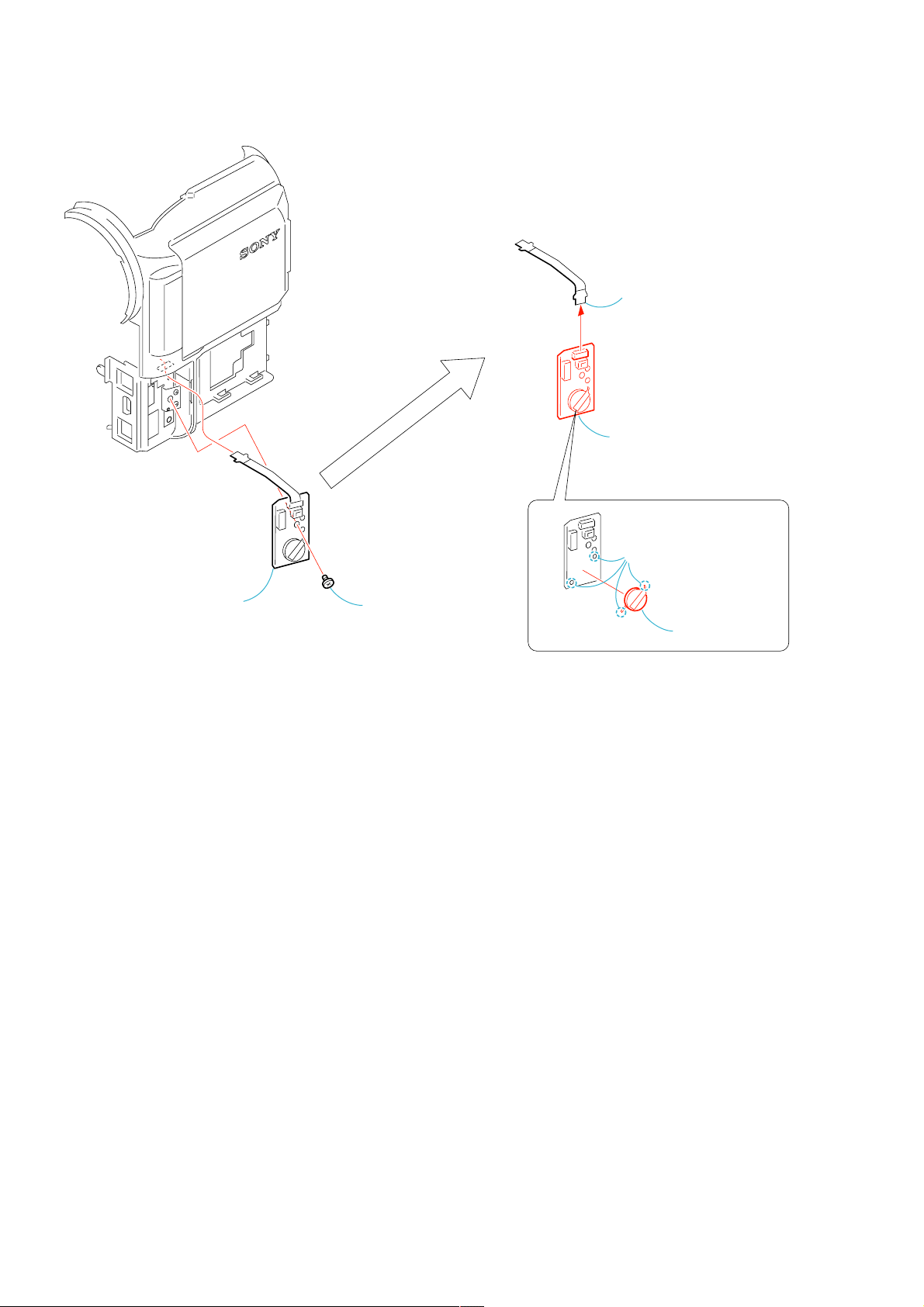
2-26.VC-325 BOARD
y
2
3
Flexible board
(from the capstan motor) (27P)
Two claws
4
Flexible board
(from the sensor) (27P)
6
Flexible board
(from the video head) (10P)
5
Flexible board
(from the drum motor) (10P)
8
VC-325 board
VC-325
1
Screw (M1.7 × 2.5),
lock ace, p2 (silver)
DCR-PC330/PC330E
7
FP-702 flexible
board (16P)
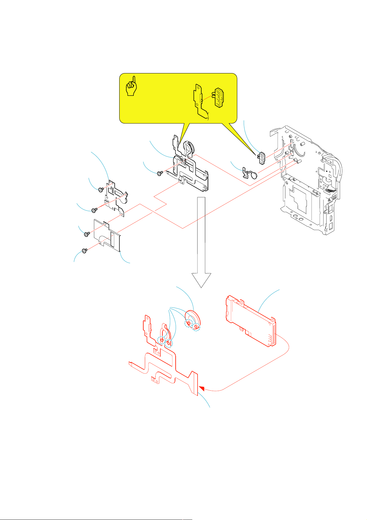
2-27.MECHANISM DECK
2
Screw (M1.7 × 2.5),
lock ace, p2 (silver)
1
Screw (M1.7 × 2.5),
lock ace, p2 (silver)
3
Mechanism deck,
MD frame assembly
6
Mechanism deck
5
MD frame assembl
4
Four screws
(M1.4
×
1.5),
2-19
 Loading...