

SONY DCR-PC100E, PC105, DCR-PC103E Service Manual
DCR-PC103E/PC104E/
PC105/PC105E
RMT-830/RMT-831
SERVICE MANUAL
Ver 1.0 2003. 04
Revision History
Revision History
Photo : DCR-PC103E
Link
Link
SPECIFICATIONS
BLOCK DIAGRAMS
BLOCK DIAGRAMS
LEVEL 2
US Model
Canadian Model
Korea Model
DCR-PC105
AEP Model
UK Model
East European Model
DCR-PC103E/PC105E
E Model
Hong Kong Model
DCR-PC104E/PC105/PC105E
Chinese Model
DCR-PC104E/PC105E
Australian Model
DCR-PC105E
Tourist Model
DCR-PC105/PC105E
Z MECHANISM
PRINTED WIRING BOARDS
PRINTED WIRING BOARDSSPECIFICATIONS
SERVICE NOTE
SERVICE NOTE
DISASSEMBLY
DISASSEMBLY
• For INSTRUCTION MANUAL, refer to SERVICE MANUAL, LEVEL 1 (987625841.pdf).
• Reference No. search on printed wiring boards is available.
On the VC-319 board
This service manual provides the information that is premised the circuit board replacement service and not intended repair
inside the VC-319 board.
Therefore, schematic diagram, printed wiring board, waveforms, mounted parts location and electrical parts list of the VC-319
board are not shown.
The following pages are not shown.
Schematic diagram .............................Pages 4-25 to 4-60
Printed wiring board............................Pages 4-77 to 4-80
Waveforms ...........................................
FRAME SCHEMATIC DIAGRAMS
FRAME SCHEMATIC DIAGRAMS
SCHEMATIC DIAGRAMS
SCHEMATIC DIAGRAMS
Mounted parts location .............................
Electrical parts list................................... Pages 5-15 to 5-23
Pages 4-85 to 4-86
REPAIR PARTS LIST
REPAIR PARTS LIST
Page 4-89 to 4-90
DIGITAL VIDEO CAMERA RECORDER

DCR-PC103E/PC104E/PC105/PC105E
COVER
COVER
Video camera
recorder
System
Video recording system
2 rotary heads
Helical scanning system
Mini DV Format (SD Specification of
Consumer-Use Digital VCR)
Audio recording system
Rotary heads, PCM system
Quantization: 12 bits (Fs 32 kHz,
stereo 1, stereo 2), 16 bits
(Fs 48 kHz, stereo)
Video signal
NTSC colour, EIA standards
(DCR-PC105 only)
PAL colour, CCIR standards
(DCR-PC103E/PC104E/PC105E only)
Usable cassette
Mini DV cassette with the
mark printed
Tape speed
SP: Approx. 18.81 mm/s
LP: Approx. 12.56 mm/s
Recording/playback time
(using cassette DVM60)
SP: 1 hour
LP: 1.5 hours
Fastforward/rewind time
(using cassette DVM60)
Approx. 2 min. and 40 seconds
Viewfinder
Electric viewfinder (Colour)
Image device
3.8 mm (1/4.7 type)
CCD (Charge Coupled Device)
Gross: Approx. 1 070 000 pixels
Effective (still)
(DCR-PC105/PC105E only):
Approx. 1 000 000 pixels
Effective (moving):
Approx. 690 000 pixels
Lens
Carl Zeiss
Combined power zoom lens
Filter diameter: 30 mm (1 3/16 in.)
10× (Optical), 120× (Digital)
F = 1.8 – 2.0
Focal length
3.7 – 37 mm (5/32 – 1 1/2 in.)
When converted to a 35 mm still
camera
In CAMERA mode:
50 – 500 mm (2 – 19 3/4 in.)
In MEMORY mode
(DCR-PC105/PC105E only):
42 – 420 mm (1 11/16 – 16 5/8 in.)
Colour temperature
Auto, HOLD, INDOOR (3 200 K),
OUTDOOR (5 800 K)
Minimum illumination
7 lx (lux) (F 1.8)
0 lx (lux) (in the NightShot mode)*
* Objects unable to be seen due to
the dark can be shot with infrared
lighting.
Input/Output connectors
Audio/Video input (DCR-PC104E/
PC105E only) /output
10-pin connector
Input/output auto switch (DCRPC104E/PC105/PC105E only)
Video signal: 1 Vp-p, 75 Ω,
unbalanced
Luminance signal: 1 Vp-p, 75 Ω,
unbalanced
Chrominance signal:
0.286 Vp-p, 75 Ω (DCR-PC105 only)
0.3 Vp-p, 75 Ω
(DCR-PC103E/PC104E/PC105E only)
unbalanced
Audio signal: 327 mV, (at output
impedance more than 47 kΩ)
Input impedance with more than
47 kΩ
(DCR-PC104E/PC105/PC105E only)
Output impedance with less than
2.2 kΩ
DV input (DCR-PC104E/PC105E
only)/output
4-pin connector
DV jack (DCR-PC105 only)
4-pin connector
Headphone jack
Stereo minijack (ø 3.5 mm)
LANC jack
Stereo mini-minijack (ø 2.5 mm)
USB jack
mini-B
MIC jack
Minijack, 0.388 mV low impedance
with 2.5 to 3.0 V DC, output
impedance 6.8 kΩ (ø 3.5 mm)
Stereo type
LCD screen
Picture
6.2 cm (2.5 type)
Total dot number
211 200 (960 × 220)
General
Power requirements
7.2 V (battery pack)
8.4 V (AC Adaptor)
SPECIFICATIONS
Average power consumption
(when using the battery pack)
During camera recording using LCD
3.7 W
(DCR-PC103E/PC104E/PC105E only)
3.8 W (DCR-PC105 only)
Viewfinder
3.1 W
(DCR-PC103E/PC104E/PC105E only)
3.2 W (DCR-PC105 only)
Operating temperature
0°C to 40°C (32°F to 104°F)
Storage temperature
–20°C to + 60°C
(–4°F to + 140°F)
Dimensions (approx.)
51 × 104 × 97 mm
(2 × 4 1/8 × 3 7/8 in.) (w/h/d)
Mass (approx.)
DCR-PC105/PC105E:
460 g (1 lb)
,
DCR-PC103E/PC104E:
440 g (1 lb)
main unit only
DCR-PC105/PC105E:
550 g (1 lb 4 oz)
DCR-PC103E/PC104E:
530 g (1 lb 3 oz)
including the rechargeable battery
pack NP-FM30 (not for sale),
cassette DVM60
Supplied accessories
See page 3.
AC Adaptor
AC-L15A/L15B
Power requirements
100 – 240 V AC, 50/60 Hz
Current consumption
0.35 – 0.18 A
Power consumption
18 W
Output voltage
DC OUT: 8.4 V, 1.5 A
Operating temperature
0°C to 40°C (32°F to 104°F)
Storage temperature
–20°C to + 60°C
(–4°F to + 140°F)
Dimensions (approx.)
56 × 31 × 100 mm
(2 1/4 × 1 1/4 × 4 in.) (w/h/d)
excluding projecting parts
Mass (approx.)
190 g (6.7 oz)
excluding mains lead
Rechargeable
battery pack
NP-FM30
Maximum output voltage
DC 8.4 V
Output voltage
DC 7.2 V
Capacity
5.0 Wh (700 mAh)
Dimensions (approx.)
38.2 × 20.5 × 55.6 mm
(1 9/16 × 13/16 × 2 1/4 in.)
(w/h/d)
Mass (approx.)
65 g (2.3 oz)
Operating temperature
0°C to 40°C (32°F to 104°F)
Type
Lithium ion
“Memory Stick”
(DCR-PC105/PC105E only)
Memory
Flash memory
8MB: MSA-8A
Operating voltage
2.7 – 3.6 V
Power consumption
Approx. 45 mA during operation
mode
Approx. 130 µA during tape
recording standby
Dimensions (approx.)
50 × 2.8 × 21.5 mm
(2 × 1/8 × 7/8 in.) (w/h/d)
Mass (approx.)
4 g (0.14 oz)
Design and specifications are subject
to change without notice.
— 2 —
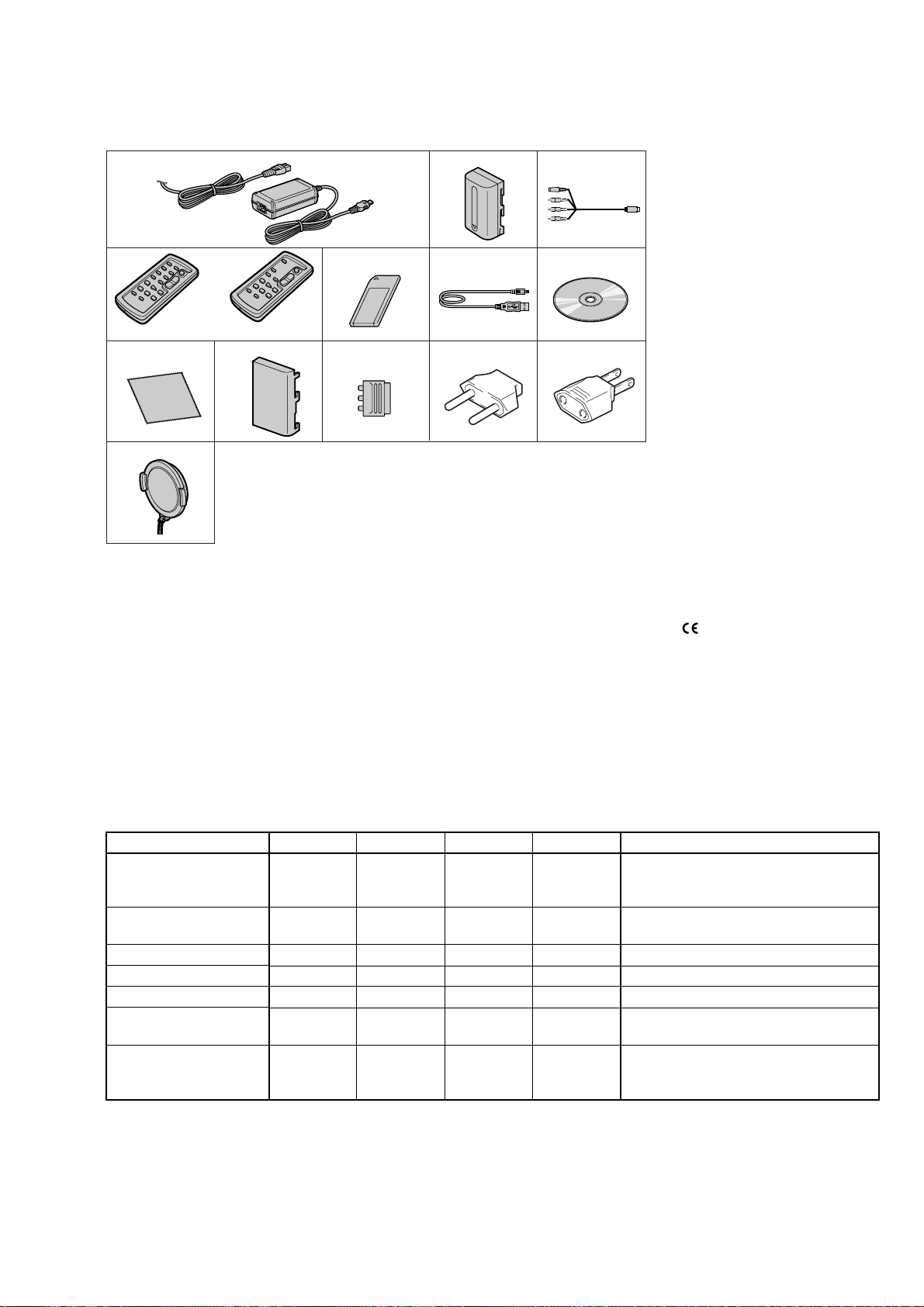
• SUPPLIED ACCESSORIES
Make sure that the following accessories are supplied with your camcorder .
DCR-PC103E/PC104E/PC105/PC105E
1
4
8
qd
1 AC-L15A/L15B AC Adaptor (1), Mains lead (1)
2 NP-FM30 rechargeable battery pack (BLUE) (1)
3 A/V connecting cable (1) (AV multi)(1.5m)
4 Wireless Remote Commander (1)
(A button type lithium battery is built in.)
RMT-831: DCR-PC105/PC105E
RMT-830: DCR-PC103E/PC104E
5 “Memory Stick” (MSA-8A) (1) (DCR-PC105/PC105E only)
6 USB cable (1)
7 CD-ROM (SPVD-010 USB Driver) (1)
9
5627
q; qa qs
3
8 Cleaning cloth (1)
9 Battery terminal cover (1)
0 21-pin adaptor (1) (Models with
printed on their bottom surfaces only)
(PC103E/PC105E: AEP, UK, EE only)
qa 2-pin Conversion adaptor (1)
(PC105: JE/PC105E: JE only)
qs 2-pin Conversion adaptor (1)
(PC104E: E, HK/PC105: E, HK/PC105E: E)
qd Lens cap (1)
mark
Table for difference of functions
DCRDestination
PC103E
AEP, UK,
EE
Color system
Remote commander
PAL
RMT-830
VTR REC
DV input
MEMORY STICK
(Digital still)
Flash
• Abbreviation
EE : East European model
HK : Hong Kong model
CH : Chinese model
CND : Canadian model
JE : Tour ist model
KR : Korea model
AUS : Australian model
PC104E
E, HK, CH
PC105
US, CND, E,
HK, JE, KR
PC105E
AEP , UK,
EE, E, HK,
Remarks
AUS, CH, JE
PAL
NTSC
PAL
NTSC: X1501 is 66MHz.
PAL: X1501 is 54MHz.
RMT-830
✕
✕
✕
✕
a
a
✕
✕
RMT-831
a
a
a
a
RMT-831
a
a
a
a
a : With Memory stick connector
a : With Flash unit (FL4400)
With D001, S005 of PS4400 block
With ST-084 board
— 3 —

DCR-PC103E/PC104E/PC105/PC105E
SAFETY-RELATED COMPONENT WARNING!!
COMPONENTS IDENTIFIED BY MARK 0 OR DOTTED LINE WITH
MARK 0 ON THE SCHEMATIC DIAGRAMS AND IN THE PARTS
LIST ARE CRITICAL TO SAFE OPERATION. REPLACE THESE
COMPONENTS WITH SONY PARTS WHOSE PART NUMBERS
APPEAR AS SHOWN IN THIS MANUAL OR IN SUPPLEMENTS
PUBLISHED BY SONY.
SAFETY CHECK-OUT
After correcting the original service problem, perform the following
safety checks before releasing the set to the customer.
1. Check the area of your repair for unsoldered or poorly-soldered
connections. Check the entire board surface for solder splashes
and bridges.
2. Check the interboard wiring to ensure that no wires are
"pinched" or contact high-wattage resistors.
3. Look for unauthorized replacement parts, particularly
transistors, that were installed during a previous repair . Point
them out to the customer and recommend their replacement.
4. Look for parts which, through functioning, show obvious signs
of deterioration. Point them out to the customer and
recommend their replacement.
5. Check the B+ voltage to see it is at the values specified.
6. Flexible Circuit Board Repairing
• Keep the temperature of the soldering iron around 270˚C
during repairing.
• Do not touch the soldering iron on the same conductor of the
circuit board (within 3 times).
• Be careful not to apply force on the conductor when soldering
or unsoldering.
ATTENTION AU COMPOSANT AYANT RAPPORT
À LA SÉCURITÉ!
LES COMPOSANTS IDENTIFÉS P AR UNE MARQUE 0 SUR LES
DIAGRAMMES SCHÉMA TIQUES ET LA LISTE DES PIÈCES SONT
CRITIQUES POUR LA SÉCURITÉ DE FONCTIONNEMENT. NE
REMPLACER CES COMPOSANTS QUE PAR DES PIÈSES SONY
DONT LES NUMÉROS SONT DONNÉS DANS CE MANUEL OU
DANS LES SUPPÉMENTS PUBLIÉS PAR SONY.
Unleaded solder
Boards requiring use of unleaded solder are printed with the leadfree mark (LF) indicating the solder contains no lead.
(Caution: Some printed circuit boards may not come printed with
the lead free mark due to their particular size.)
: LEAD FREE MARK
Unleaded solder has the following characteristics.
• Unleaded solder melts at a temperature about 40°C higher than
ordinary solder.
Ordinary soldering irons can be used but the iron tip has to be
applied to the solder joint for a slightly longer time.
Soldering irons using a temperature regulator should be set to
about 350°C.
Caution: The printed pattern (copper foil) may peel away if the
heated tip is applied for too long, so be careful!
• Strong viscosity
Unleaded solder is more viscous (sticky, less prone to flow) than
ordinary solder so use caution not to let solder bridges occur such
as on IC pins, etc.
• Usable with ordinary solder
It is best to use only unleaded solder but unleaded solder may
also be added to ordinary solder.
— 4 —

TABLE OF CONTENTS
1. SERVICE NOTE
1-1. SERVICE NOTE ····························································· 1-1
1. POWER SUPPLY DURING REPAIRS ··························1-1
2. TO TAKE OUT A CASSETTE WHEN NOT EJECT
(FORCE EJECT) ····························································· 1-1
3. HOW TO OPEN THE FLASH WHEN THE FLASH
DOSEN’T OPEN (DCR-PC105/PC105E) ······················1-1
4. DISCHARGING OF THE FLASHLIGHT POWER
SUPPLY CAPACITOR (DCR-PC105/PC105E) ············· 1-2
1-2. SELF-DIAGNOSIS FUNCTION····································1-3
1. SELF-DIAGNOSIS FUNCTION····································1-3
2. SELF-DIAGNOSIS DISPLAY ·······································1-3
3. SELF-DIAGNOSIS CODE TABLE································1-4
2. DISASSEMBLY
2-1. LCD CABINET (R) ························································2-2
2-2. CABINET (FRONT) ASSEMBLY ·································2-3
2-3. CABINET (G) ASSEMBLY ··········································· 2-3
2-4. CABINET (L)··································································2-4
2-5. ST CABINET (UPPER) ASSEMBLY ····························2-4
2-6. CABINET (R) SECTION ···············································2-5
2-7. BATTERY HOLDER ······················································2-6
2-8. BJ-004 BOARD······························································· 2-7
2-9. BLIND PLATE ASSEMBLY ··········································2-8
2-10. HINGE SECTION ···························································2-9
2-11. LCD HINGE ASSEMBLY ············································2-10
2-12. PD-193 BOARD ····························································2-11
2-13. CABINET (REAR) ·······················································2-11
2-14. CONTROL SWITCH BLOCK (PS4400) ·····················2-12
2-15. ST-084 BOARD (PC105/PC105E) ·······························2-12
2-16. LENS/EVF/ST SECTION-1 ·········································2-13
2-17. LENS/EVF/ST SECTION-2 ·········································2-13
2-18. EVF SECTION ······························································2-14
2-19. VF-156 BOARD ····························································2-15
2-20. MF RING ASSEMBLY·················································2-16
2-21. LENS SECTION ··························································· 2-16
2-22. LENS DEVICE (LSV-751A) ········································2-17
2-23. EXTERNAL CONNECTOR (HOT SHOE) ·················2-18
2-24. FLASH UNIT (FL4400) (PC105/PC105E) ··················2-19
2-25. HP RETAINER ASSEMBLY, MEMORY STICK
CONNECTOR (PC105/PC105E)··································2-20
2-26. CONTROL SWITCH BLOCK (FK4400)·····················2-21
2-27. NS-018 BOARD, FK FRAME ASSEMBLY ················2-22
2-28. VC-319 BOARD ··························································· 2-22
2-29. MECHANISM DECK (Z100) ·······································2-23
2-30. CIRCUIT BOARDS LOCATION ·································2-25
2-31. FLEXIBLE BOARDS LOCATION ······························2-26
DCR-PC103E/PC104E/PC105/PC105E
• CONTROL SWITCH BLOCK (FK4400) (MS, AUDIO
OUT)
SCHEMATIC DIAGRAM ····························4-11
• LI-070 (BATTERY)
SCHEMATIC DIAGRAM ····························4-12
• BJ-004 (JACK)
SCHEMATIC DIAGRAM ····························4-13
• FP-697 FLEXIBLE
SCHEMATIC DIAGRAM ····························4-14
• ST-084 (FLASH DRIVER)
SCHEMATIC DIAGRAM ····························4-15
• FLASH UNIT (FL4400)
SCHEMATIC DIAGRAM ····························4-16
• VF-156 (1/2) (MIC AMP)
SCHEMATIC DIAGRAM ····························4-17
• VF-156 (2/2) (JACK)
SCHEMATIC DIAGRAM ····························4-19
• NS-018 (SIRCS,NS)
SCHEMATIC DIAGRAM ····························4-21
• CONTROL SWITCH BLOCK (PS4400) (FUNCTION
KEY)
SCHEMATIC DIAGRAM ····························4-22
• FP-467/468/228 FLEXIBLE (MD BLOCK)
SCHEMATIC DIAGRAM ····························4-23
Shematic diagram of the VC-319 board are not shown.
Pages from 4-25 to 4-60 are not shown.
4-3. PRINTED WIRING BOARDS
• CD-444 (CCD IMAGER)
PRINTED WIRING BOARD ·······················4-63
• FP-672 FLEXIBLE (MF SENSOR)
PRINTED WIRING BOARD ·······················4-65
• LI-070 (BATTERY)
PRINTED WIRING BOARD ·······················4-65
• FP-697 FLEXIBLE
PRINTED WIRING BOARD ·······················4-67
• NS-018 (SIRCS,NS)
PRINTED WIRING BOARD ·······················4-67
• PD-193 (LCD RGB DRIVE)
PRINTED WIRING BOARD ·······················4-67
• BJ-004 (JACK)
PRINTED WIRING BOARD ·······················4-69
• ST-084 (FLASH DRIVER)
PRINTED WIRING BOARD ·······················4-71
• VF-156 (MIC AMP, JACK)
PRINTED WIRING BOARD ·······················4-73
3. BLOCK DIAGRAMS
3-1. OVERALL BLOCK DIAGRAM (1/4) ···························3-1
3-2. OVERALL BLOCK DIAGRAM (2/4) ···························3-3
3-3. OVERALL BLOCK DIAGRAM (3/4) ···························3-5
3-4. OVERALL BLOCK DIAGRAM (4/4) ···························3-7
3-5. POWER BLOCK DIAGRAM (1/2) ································3-9
3-6. POWER BLOCK DIAGRAM (2/2) ······························3-11
4. PRINTED WIRING BOARDS AND
SCHEMATIC DIAGRAMS
4-1. FRAME SCHEMATIC DIAGRAM (1/2) ·······················4-1
FRAME SCHEMATIC DIAGRAM (2/2) ······················· 4-3
4-2. SCHEMATIC DIAGRAMS
• CD-444 (CCD IMAGER)
SCHEMATIC DIAGRAM ······························4-7
• FP-672 FLEXIBLE (MF SENSOR)
SCHEMATIC DIAGRAM ······························4-8
• PD-193 (LCD RGB DRIVE)
SCHEMATIC DIAGRAM ······························4-9
Printed wiring board of the VC-319 board are not shown.
Pages from 4-77 to 4-80 are not shown.
• FP-467/468/228 FLEXIBLE BOARD
(MD BLOCK) ·····························································4-81
4-4. WAVEFORMS ······························································4-83
Waveforms of the VC-319 board are not shown.
Pages 4-85 to 4-86 are not shown.
4-5. MOUNTED PARTS LOCATION ·································4-87
Mounted parts location of the VC-319 board is not shown.
Page 4-89 to 4-90 is not shown.
— 5 —

DCR-PC103E/PC104E/PC105/PC105E
5. REPAIR PARTS LIST
5-1. EXPLODED VIEWS ······················································ 5-1
5-1-1.OVERALL SECTION·····················································5-3
5-1-2.VTR COMPLETE SECTION ·········································5-4
5-1-3.LENS/EVF/ST SECTION···············································5-5
5-1-4.STROBOSCOPE SECTION ···········································5-6
5-1-5.EVF SECTION································································5-7
5-1-6.CABINET (R) SECTION-1 ············································5-8
5-1-7. CABINET (R) SECTION-2············································5-9
5-1-8.MECHANISM DECK OVERALL (Z100) ···················5-10
5-1-9.LS CHASSIS BLOCK ASSEMBLY ·····························5-11
5-1-10. MECHANICAL CHASSIS BLOCK ASSEMBLY ····5-12
5-2. ELECTRICAL PARTS LIST ········································5-13
Parts list of the VC-319 board are not shown.
Pages from 5-15 to 5-23 are not shown.
— 6 —
DCR-PC103E/PC104E/PC105/PC105E
COVER
COVER
SECTION 1
SERVICE NOTE
1-1. SERVICE NOTE
1. POWER SUPPLY DURING REPAIRS
In this unit, about 10 seconds after power is supplied to the battery terminal using the regulated power supply (8.4V), the po wer is shut of f so
that the unit cannot operate.
This following two methods are available to prevent this. Take note of which to use during repairs.
Method 1.
Use the AC power adaptor (AC-L10, AC-VQ800 etc.).
Method 2.
Connect the servicing remote commander RM-95 (J-6082-053-B) to the LANC jack, and set the commander switch to the “ADJ” side.
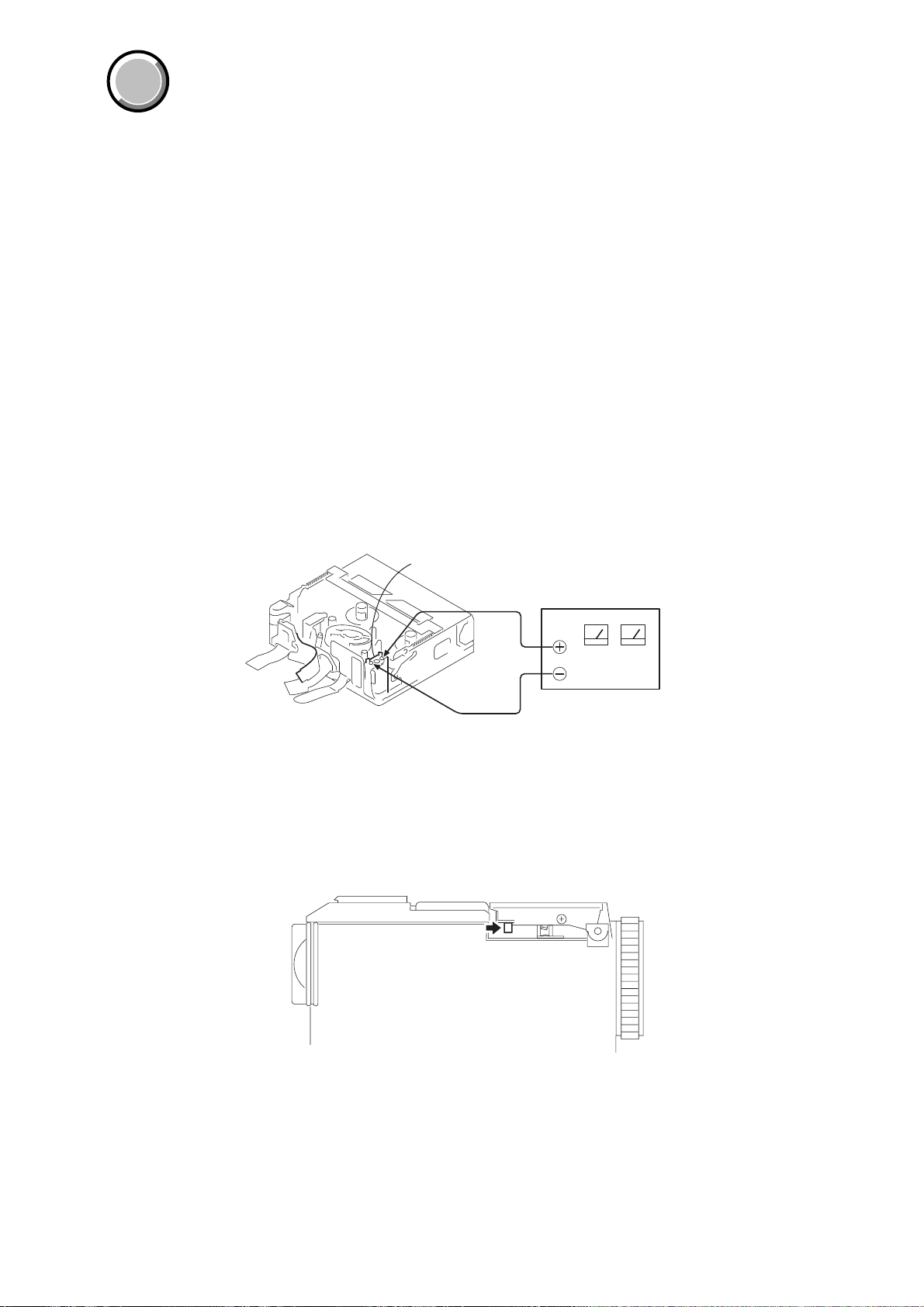
2. TO TAKE OUT A CASSETTE WHEN NOT EJECT (FORCE EJECT)
1 Only for DCR-PC105/PC105E, open the flash.
2 Only for DCR-PC105/PC105E, refer to “3. DISCHARGING OF THE FLASHLIGHT POWER SUPPLY CAPACITOR” to discharge
the flash power supply capacitor.
3 Refer to 2-2., 2-3. and 2-4. to remove the cabinet (front) assembly, cabinet (G) assembly and cabinet (L).
4 Refer to 2-6. to remove the cabinet (R) section.
5 Refer to 2-13. and 2-14. to remove the cabinet (rear), control switch block (PS4400).
6 Refer to 2-15., 2-16. and 2-17. to remove the ST-084 board and LENS/EVF/ST section.
7 Refer to 2-28., 2-29. to remove the VC-319 board and mechanism deck (Z100).
8 Supply +4.5V from the DC power supply to the loading motor and unload with a pressing the cassette compartment.
Loading motor
DC power supply (+4.5Vdc)
3. HOW TO OPEN THE FLASH WHEN THE FLASH DOSEN’T OPEN (DCR-PC105/PC105E)
1 Refer to 2-3. and 2-4. to remove cabinet (G) assembly and cabinet (L).
2 Push the part pointed out with the arrow in the direction of the arrow.
1-1
DCR-PC103E/PC104E/PC105/PC105E
y
D
4. DISCHARGING OF THE FLASHLIGHT POWER SUPPLY CAPACITOR (DCR-PC105/PC105E)
The power supply capacitor (C6606) of the ST-084 board is charged up to the maximum 300V potential.
There is a danger of electric shock by this high voltage when the capacitor is handled by hand. The electric shock is caused by the charged
voltage which is kept without discharging when the main power of the unit is simply turned off. Therefore, the remaining voltage must be
discharged as described below.
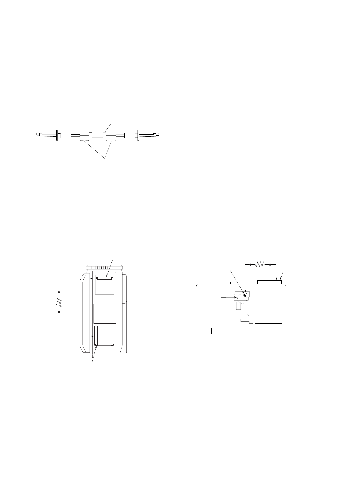
4-1. PREPARING THE SHORT JIG
To preparing the short jig. a small clip is attached to each end of a resistor of 1kΩ/1W (1-215-869-119)
Wrap insulating tape fully around the reads of the resistor to prevent electric shock.
1 kΩ/1 W
Wrap insulating tape.
4-2. DISCHARGING THE CAPACITOR (DCR-PC105/PC105E)
Discharging method (1):
1 Open the flash.
2 Remove the power supply (Battery or AC power adaptor).
3 Remove the ST cabinet (Upper).
4 Short-circuit between the Xenon tube anode and the GND
(GND of the accessory shoe) with the short jig about 10 seconds.
Xenon tube
AK
Short jig
Discharging method (2):
1 Remove the power supply (Battery or AC power adaptor).
2 Refer to 2-2. to remove the cabinet (front) section.
3 Refer to 2-6. to release the cassette cover lock and remo v e the
cabinet (R) section.
4 Short-circuit between the TP6600 of the ST-084 board and the
GND (GND of the accessory shoe) with the short jig about 10
seconds.
Short jig
ST-084 board TP6600
C6606
Accessor
shoe GN
Accessory shoe GND
1-2
1-2. SELF-DIAGNOSIS FUNCTION
1. SELF-DIAGNOSIS FUNCTION
When problems occur while the unit is operating, the self-diagnosis
function starts working, and displays on the viewfinder, or LCD
screen what to do.
Details of the self-diagnosis functions are provided in the Instruction
manual.
Viewfinder or LCD screen
C : 3 1 : 1 1
Blinks at 3.2Hz
DCR-PC103E/PC104E/PC105/PC105E
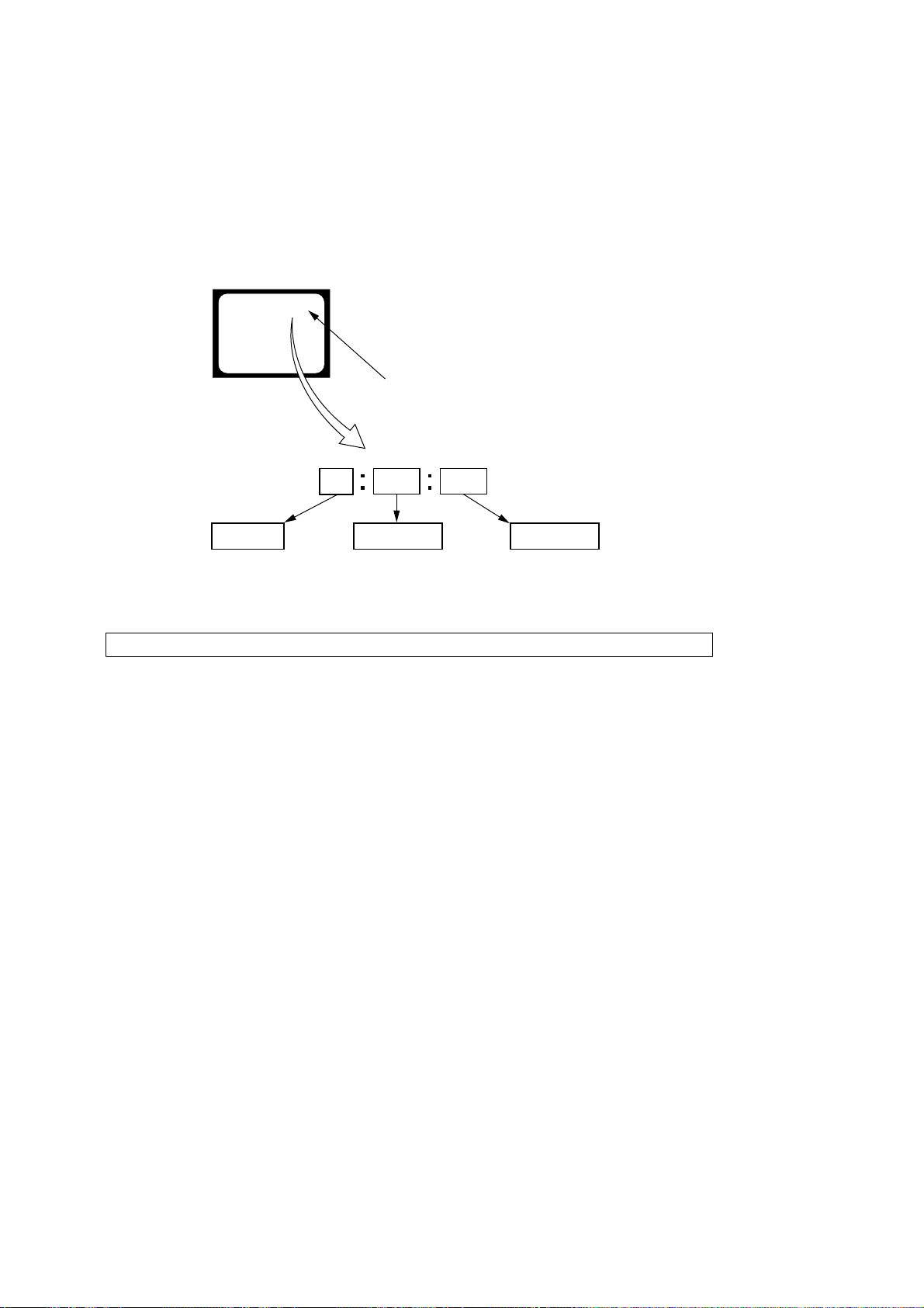
2. SELF-DIAGNOSIS DISPLAY
When problems occur while the unit is operating, the counter of the
viewfinder or LCD screen consists of an alphabet and 4-digit number ,
which blinks at 3.2Hz. This 5-character display indicates the
“repaired by:”, “block” in which the problem occurred, and “detailed
code” of the problem.
3 1C
Repaired by:
C : Corrected by customer
H : Corrected by dealer
E : Corrected by service
engineer
Note: The “self-diagnosis display” data will be kept even if the lithium battery (BT6401 of LI-070 board) is removed.
Indicates the appropriate
step to be taken.
E.g.
31 ....Reload the tape.
32 ....Turn on power again.
Block
1 1
Detailed Code
Refer to page 1-4.
Self-diagnosis Code Table.
1-3

DCR-PC103E/PC104E/PC105/PC105E
3. SELF-DIAGNOSIS CODE TABLE
Self-diagnosis Code
Function
Repaired by:
C
C
C
C
C
C
C
C
C
C
C
C
C
C
C
C
C
C
C
C
C
C
C
E
E
E
E
E
Block
04
21
22
31
31
31
31
31
31
31
31
31
31
31
31
32
32
32
32
32
32
32
32
61
61
62
62
91
Detailed
Code
00
00
00
10
11
20
21
22
23
24
30
40
42
10
11
20
21
22
23
24
30
40
42
00
10
00
01
01
Symptom/State
Non-standard battery is used.
Condensation.
Video head is dirty.
LOAD direction. Loading does not
complete within specified time
UNLOAD direction. Loading does not
complete within specified time
T reel side tape slacking when unloading
Winding S reel fault when counting the
rest of tape.
T reel fault.
S reel fault.
T reel fault.
FG fault when starting capstan.
FG fault when starting drum.
FG fault during normal drum operations.
LOAD direction loading motor time-
out.
UNLOAD direction loading motor
time-out.
T reel side tape slacking when
unloading.
Winding S reel fault when counting the
rest of tape.
T reel fault.
S reel fault.
T reel fault.
FG fault when starting capstan.
FG fault when starting drum
FG fault during normal drum
operations
Difficult to adjust focus
(Cannot initialize focus.)
Zoom operations fault
(Cannot initialize zoom lens.)
Steadyshot function does not work well.
(With pitch angular velocity sensor output
stopped.)
Steadyshot function does not work well.
(With yaw angular v elocity sensor output
stopped.)
Abnormality when the power supply
capacitor of the flash unit is being
charged.
Correction
Use the info LITHIUM battery.
Remove the cassette, and insert it again after one hour.
Clean with the optional cleaning cassette.
Load the tape again, and perform operations from the beginning.
Load the tape again, and perform operations from the beginning.
.
Load the tape again, and perform operations from the beginning.
Load the tape again, and perform operations from the beginning.
Load the tape again, and perform operations from the beginning.
Load the tape again, and perform operations from the beginning.
Load the tape again, and perform operations from the beginning.
Load the tape again, and perform operations from the beginning.
Load the tape again, and perform operations from the beginning.
Load the tape again, and perform operations from the beginning.
Remove the battery or power cable, connect, and perform
operations from the beginning.
Remove the battery or power cable, connect, and perform
operations from the beginning.
Remove the battery or power cable, connect, and perform
operations from the beginning.
Remove the battery or power cable, connect, and perform
operations from the beginning.
Remove the battery or power cable, connect, and perform
operations from the beginning.
Remove the battery or power cable, connect, and perform
operations from the beginning.
Remove the battery or power cable, connect, and perform
operations from the beginning.
Remove the battery or power cable, connect, and perform
operations from the beginning.
Remove the battery or power cable, connect, and perform
operations from the beginning.
Remove the battery or power cable, connect, and perform
operations from the beginning.
Inspect the lens block focus MR sensor (Pin ql, w; of CN1013 of
VC-319 board) when focusing is performed when the focus ring is
operated in the focus manual mode, and the focus motor drive circuit
(IC1301 of VC-313 board) when the focusing is not performed.
Inspect the lens block zoom MR sensor (
VC-319 board
is operated and the zoom motor drive circuit (IC1301 of VC-319
board) when zooming is not performed.
Inspect pitch angular velocity sensor (SE5202 of CD-444 board)
peripheral circuits.
Inspect yaw angular velocity sensor (SE5201 of CD-444 board)
peripheral circuits.
Checking or replacement of the flash unit.
) when zooming is performed when the zoom switch
Pin 8, 0 of CN1013 of
1-4E
DCR-PC103E/PC104E/PC105/PC105E
PD-193 board
service position
SERVICE POSITION TO
CHECK THE VTR SECTION
(PC105/PC105E)
Discharging the Capacitor
(PC105/PC105E)
DISASSEMBLY
HELP
DISASSEMBLY
DISASSEMBLY
DISASSEMBLY
DISASSEMBLY
DISASSEMBLY
DISASSEMBLY
DISASSEMBLY
DISASSEMBLY
DISASSEMBLY
DISASSEMBLY
DISASSEMBLY
DISASSEMBLY
HELP
HELP
DISASSEMBLY
DISASSEMBLY
HELP
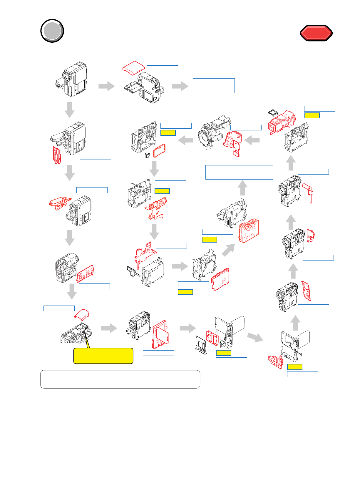
1 2-2. CABINET (FRONT) ASSEMBLY .....................
2 2-3.
CABINET (G) ASSEMBLY...............................
3 2-4.
CABINET (L)....................................................
4 2-5. ST CABINET (UPPER) ASSEMBLY................
5 2-6.
CABINET (R) SECTION..................................
6 2-7. BATTERY HOLDER.........................................
7 2-8.
BJ-004 BOARD................................................
8 2-13.
CABINET (REAR)..........................................
9 2-14.
CONTROL SWITCH BLOCK (PS4400).........
0 2-15.
ST-084 BOARD (PC105/PC105E).................
qa 2-16. LENS/EVF/ST SECTION-1............................
(page 2-3)
(page 2-3)
(page 2-4)
(page 2-4)
(page 2-5)
(page 2-6)
(page 2-7)
(page 2-11)
(page 2-12)
(page 2-12)
(page 2-13)
qs 2-17.
LENS/EVF/ST SECTION-2................................
qd 2-18. EVF SECTION...................................................
qf 2-25.
HR RETAINER ASSEMBLY,
MEMORY STICK CONNECTOR
(PC105/PC105E)...............................................
qg 2-26. CONTROL SWITCH BLOCK (FK4400).............
qh 2-27. NS-018 BOARD, FK FRAME ASSEMBLY.........
qj 2-28. VC-319 BOARD.................................................
qk 2-29. MECHANISM DECK (Z100)..............................
ql
SERVICE POSITION TO CHECK
THE VTR SECTION....................................................
(page 2-13)
(page 2-14)
(page 2-20)
(page 2-21)
(page 2-22)
(page 2-22)
(page 2-23)
(page 2-24)
PROCEDURE OF REMOVING THE MECHANISM DECK.
(VTR CHECK SERVICE POSITION)
DISASSEMBLY
HELP
DISASSEMBLY
HELP
DISASSEMBLY
HELP
COVER
COVER
SECTION 2
DISASSEMBLY
The following flow chart shows the disassembly procedure.
HELP
HELP
2-1
DCR-PC103E/PC104E/PC105/PC105E
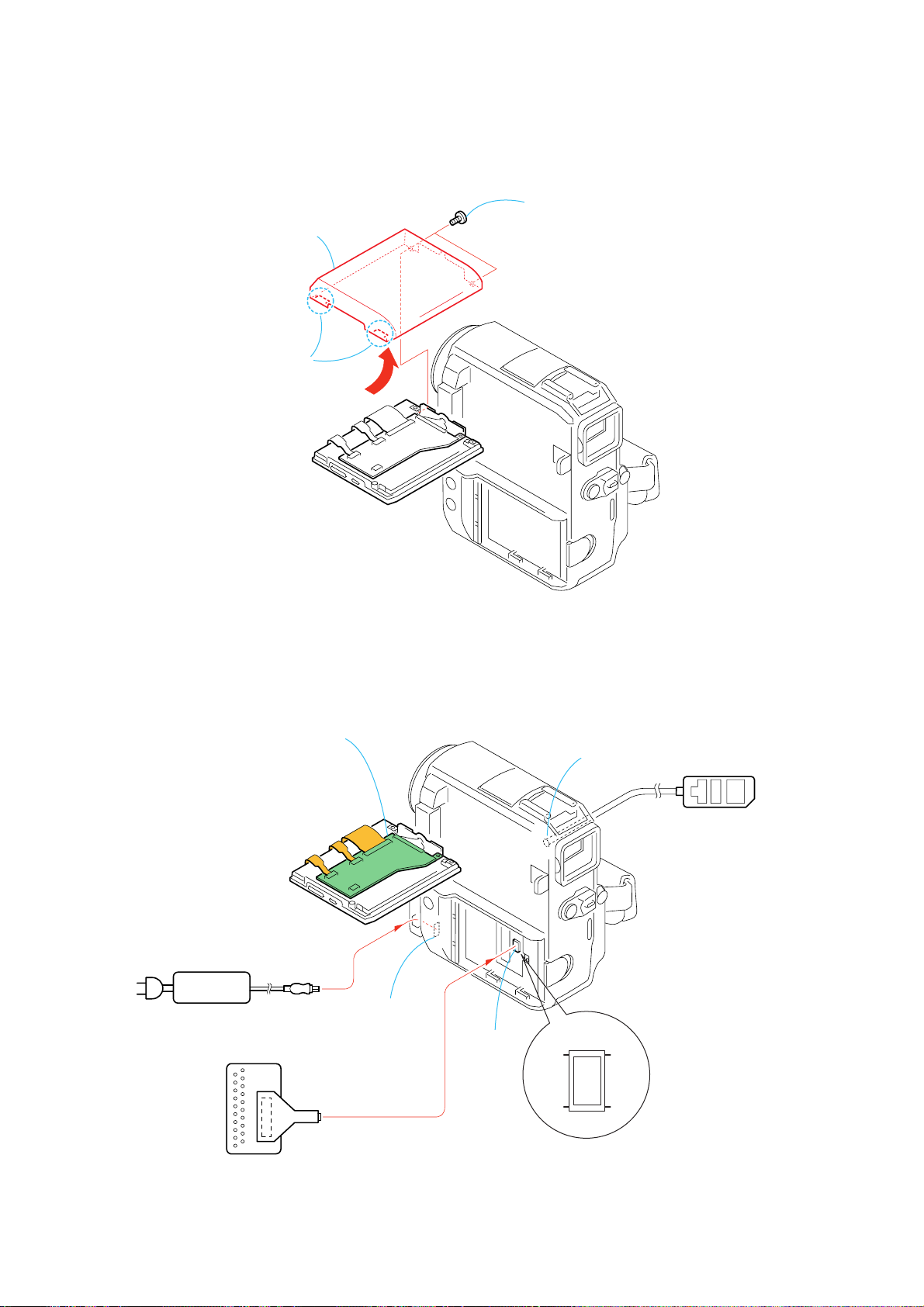
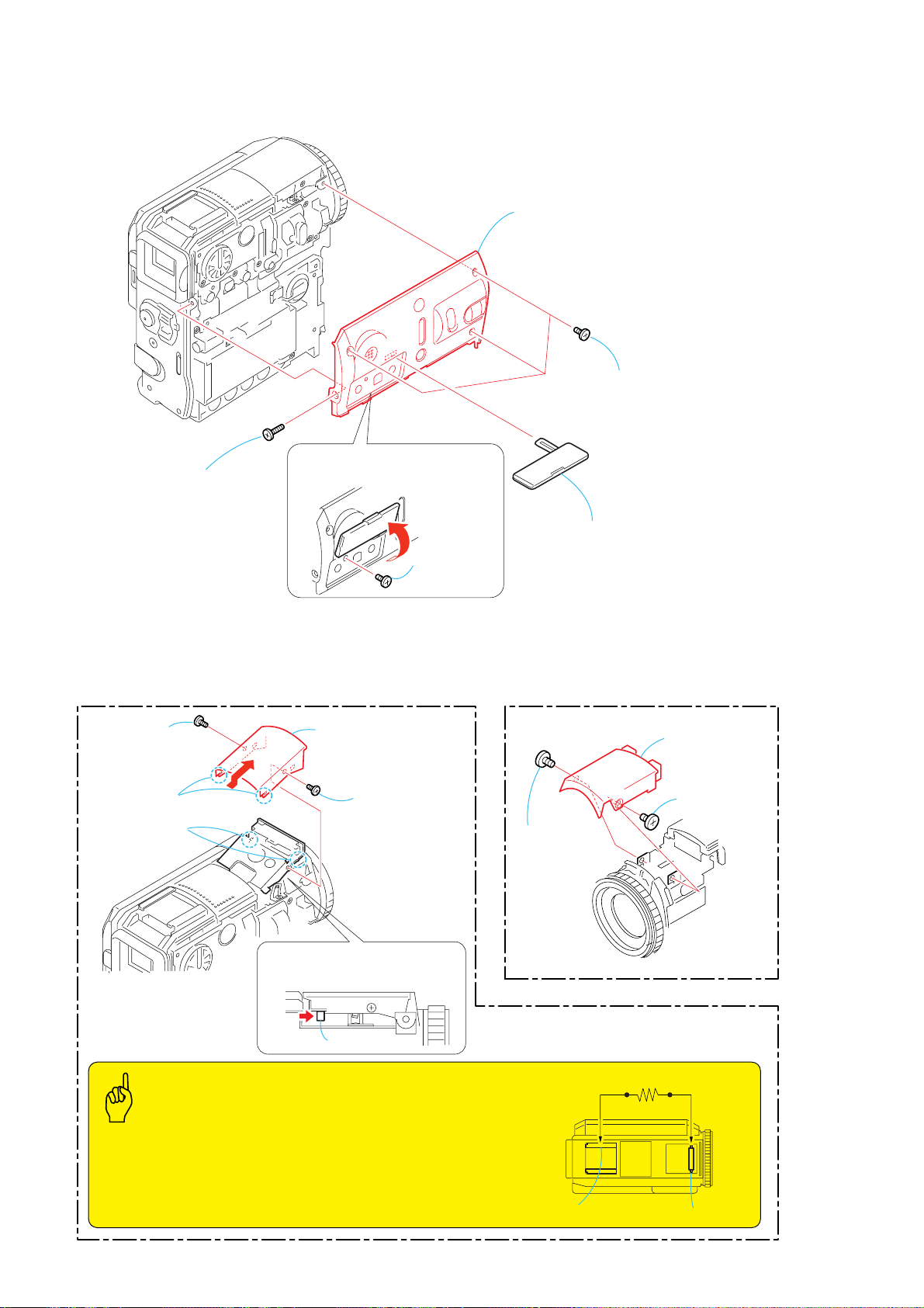
2-1. LCD CABINET (R)
3
LCD cabinet (R)
2
Two claws
PD-193
1
Two screws
×
(M1.7
lock ace, p2
2.5),
[PD-193 BOARD SERVICE POSITION]
PD-193 board
AC IN
AC power
adaptor
CPC-6 jig
(J-6082-371-A)
CPC-6 flexible jig
(J-6082-370-C)
PD-193
DC IN connector
CN1018
19
1
LANC jack
CN1018
20
2
Adjustment remote
commander (RM-95)
2-2
2-2. CABINET (FRONT) ASSEMBLY
4
Open the cassette lid.
Caution
When attaching the cabinet
(front) assembly, be careful
not to damage the claw.
7
Cabinet (front) assembly
5
Screw
(M1.7
lock ace, p2
×
2.5),
6
Two Claws
DCR-PC103E/PC104E/PC105/PC105E
Caution
When installing the cabinet
(front) assembly, install it while
pushing the flexible boards
(from the lens device and the
NS-018 board) in the direction
of the arrow.
Flexible board
(from the NS-018 board)
3
Screw
(M1.7
lock ace, p2
×
2.5),
2-3. CABINET (G) ASSEMBLY
Float the cabinet (G) assembly
5
and remove the eject knob
from the hole of the Cabinet
(G) assembly.
Eject knob
2
1
Three screws
(M1.7
lock ace, p2
×
2.5),
1
Open the jack cover
6
Remove the cabinet (G) assembly
in the direction of the arrow
Screw (M1.7 × 4),
lock ace, p2 (black)
A
A
.
Flexible board
(from the lens device)
3
Open the jack
cover (HP)
4
Open the cassette lid.
Caution
Be careful not to drop the eject knob.
2
Two screws
(M1.7
lock ace, p2
×
2.5),
2-3
8
Eject knob
7
Claw
DCR-PC103E/PC104E/PC105/PC105E
2-4. CABINET (L)
2
Flip over the jack cover
1
Screw
(M1.7
lock ace, p2
×
4),
(L) assembly.
5
Cabinet (L)
4
Three screws
(M1.7
lock ace, p2
6
Jack cover (L) assembly
×
2.5),
2-5. ST CABINET (UPPER) ASSEMBLY
(PC105/PC105E)
3
EG grip
(M1.7 × 2.5)
5
Two claws
4
Two claws
6
ST cabinet (upper)
assembly
2
EG grip
(M1.7 × 2.5)
1
Push the portion A in the
direction of the arrow to open
the Flash.
3
Screw
(M1.7
lock ace, p2
×
2.5),
(PC103E/PC104E)
1
EG grip
(M1.7 × 2.5)
3
ST cabinet (N)
assembly
2
EG grip
(M1.7 × 2.5)
A
Caution
Note: The power supply capacitor of the flash unit is charged to the high tension
voltage as high as 300 V at a maximum. You will get electrical shock when
you touch the terminal of the charged capacitor . The charged potential
remains even after the main power of the machine is turned off. Discharge
the remaining power in the capacitor referring to Service Note
(See page 1-2). High-voltage cautions. Short jig (R: 1k
2-4
Ω
/1W)
Accessory shoe GND
Short jig (R: 1kΩ/1W)
A
K
Xenon tube
2-6. CABINET (R) SECTION
7
Screw
×
(M1.7
lock ace, p2
4),
8
Screw
×
(M1.7
lock ace, p2
2.5),
DCR-PC103E/PC104E/PC105/PC105E
Caution
When installing the cabinet (R) section, install
it while the LCD unit is in the opened condition.
4
Remove the connector.
2
Two claws
9
Cabinet (R) section
3
CPC lid
6
Three screws
(M1.7
lock ace, p2
5
Open the LCD unit.
×
2.5),
1
Screw
×
(M1.7
lock ace, p2
2.5),
2-5
DCR-PC103E/PC104E/PC105/PC105E
2-7. BATTERY HOLDER
5
Radiation sheet (R)
6
Battery bracket
1
Two screws
(M1.7
lock ace, p2
×
2.5),
3
Screw
(M1.7
lock ace, p2
×
2.5),
4
Screw
8
Battery holder
2
Four screws (M1.7 × 4),
lock ace, p2
Caution
Radiation sheet (R)
Battery bracket
7
Flip over the BJ-004 board.
2-6
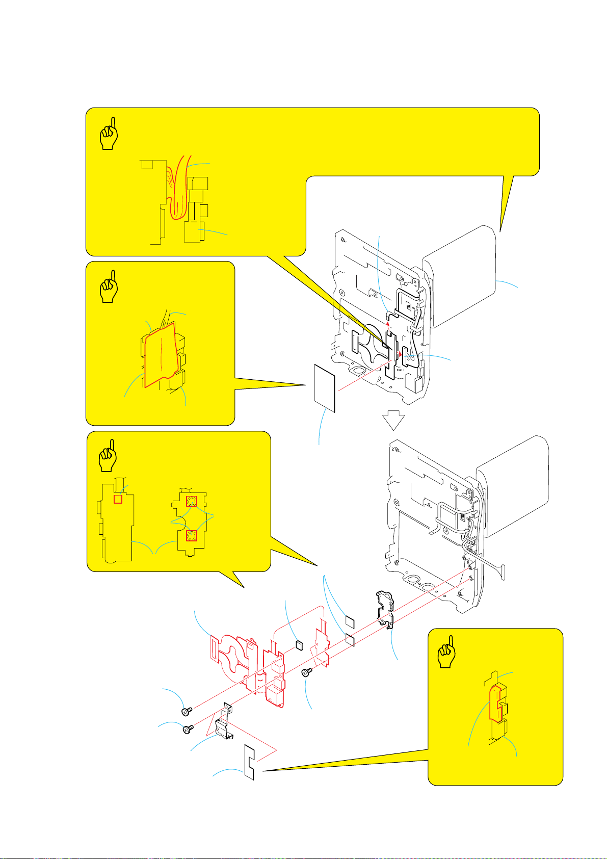
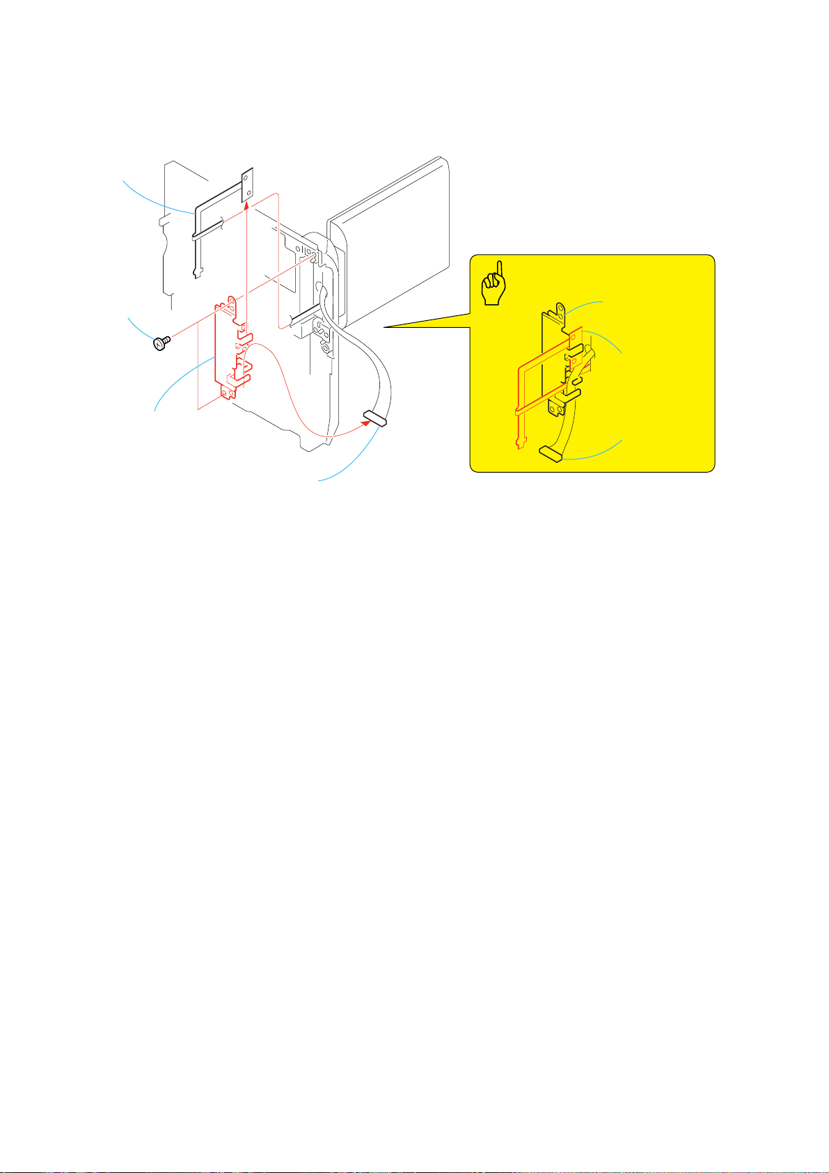
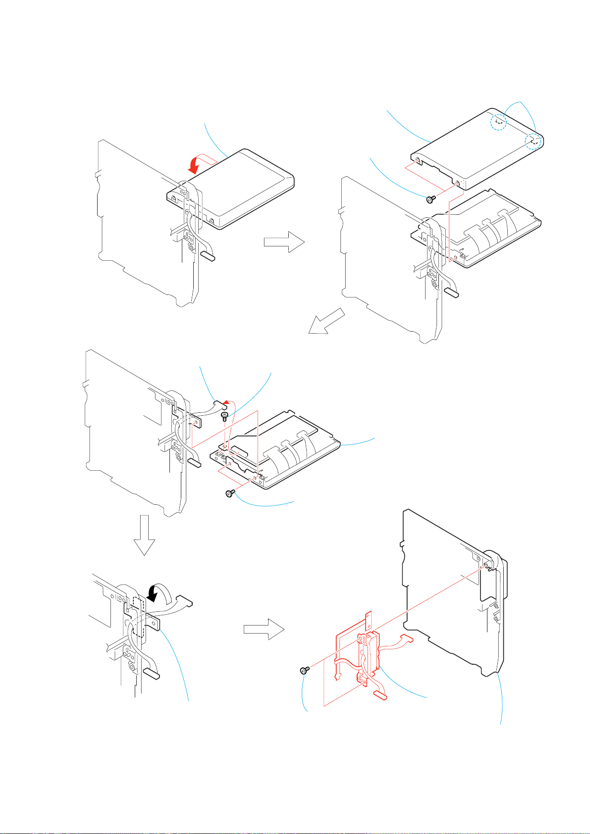
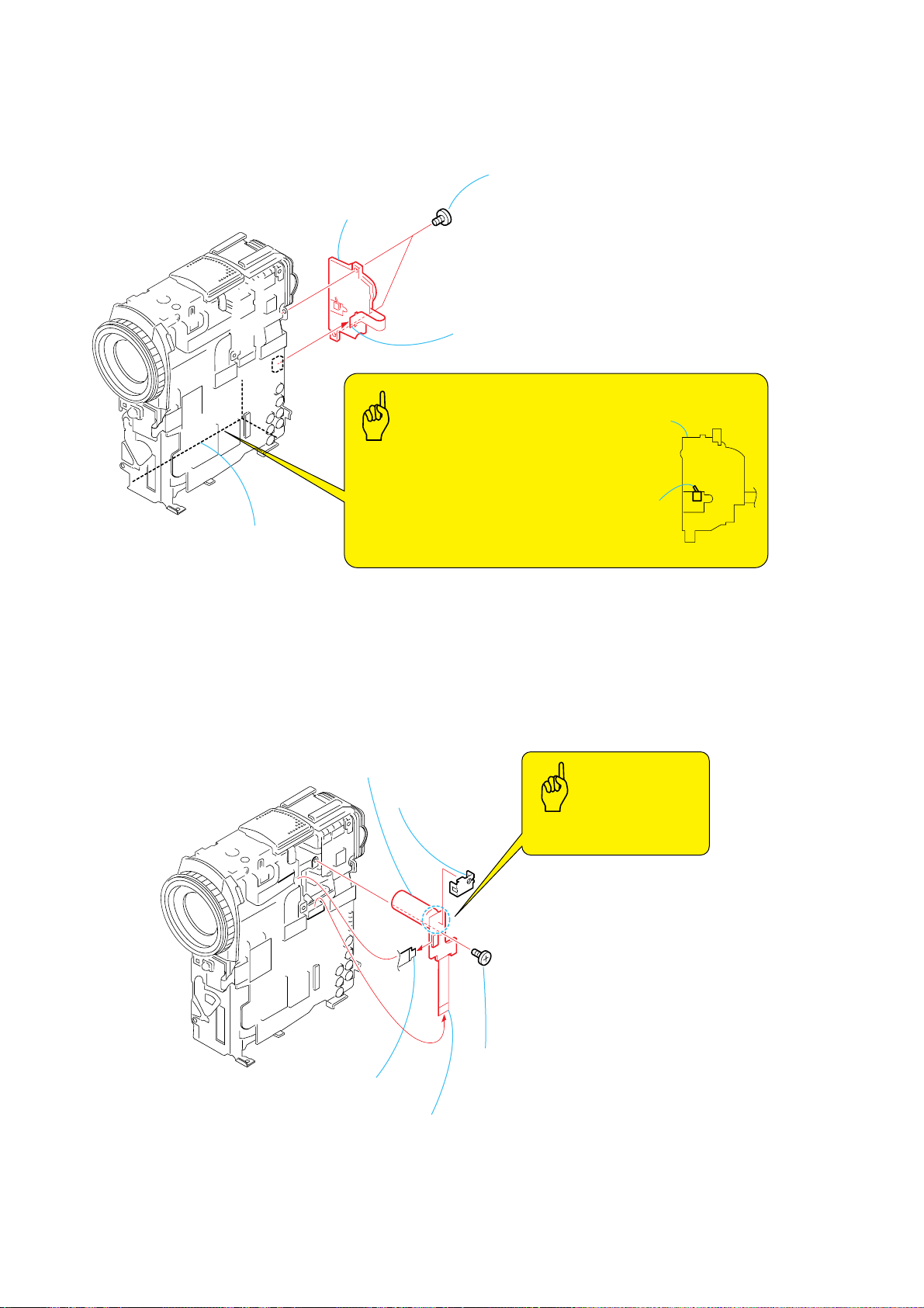
2-8. BJ-004 BOARD
Caution
BJ-004 board
Harness
Fixed DC
connector plate
DCR-PC103E/PC104E/PC105/PC105E
When attaching the harness flixed sheet, insert the harness
in the groove in between the fixed DC connector plate and the
BJ-004 board.
This attachment work must be executed while the LCD unit is
in the opened condition.
1
FP-697 flexible board
(6P)
Caution
BJ-004 board
Harness fixed sheet
Fixed DC connector plate
Caution
Cushion (CF)
Switch
block
BJ-004 board
Harness
qs
BJ-004 board
Muffle sheet
(small)
qa
Cushion (CF)
2
Harness
fixed sheet
0
Muffle sheet
(small)
3
Harness (PB-052)
(20P)
LCD unit
7
Screw
×
(M1.7
lock ace, p2
5
Two screws
(M1.7
lock ace, p2
6
Fixed DC connector plate
2.5),
×
2.5),
4
Harness protection sheet
8
Two screws
(M1.7
lock ace, p2
×
2.5),
2-7
9
CF button
Caution
Harness protection
sheet
Fixed DC
connector plate
BJ-004
board
DCR-PC103E/PC104E/PC105/PC105E
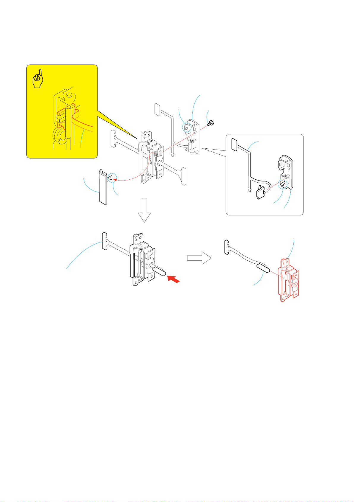
2-9. BLIND PLATE ASSEMBLY
3
FP-697 board
1
Two screws
(M1.7 × 2.5),
lock ace, p2
4
Blind plate assembly
Caution
Blind plate assembly
FP-697 board
Harness (PB-052)
2
Harness (PB-052)
2-8
2-10.HINGE SECTION
s
1
Remove the LCD unit
in the direction of the arrow.
DCR-PC103E/PC104E/PC105/PC105E
3
4
LCD cabinet (R)
2
Two screws
(M1.7
lock ace, p2
×
2.5),
PD-193
Two claw
7
Harness (PB-052)
(20P)
5
Screw
×
(M1.7
lock ace, p2
PD-193
2.5),
6
Two screws
(M1.7
lock ace, p2
×
2.5),
8
LCD cabinet section
9
Turn over the LCD hinge assembly
in the direction of the arrow.
0
Two screws
×
(M1.7
lock ace, p2
4),
2-9
qs
Hinge section
qa
Cabinet (R)
assembly
DCR-PC103E/PC104E/PC105/PC105E
2-11. LCD HINGE ASSEMBLY
Caution
FP-697 board
5
Hinge cover
(front)
2
Claw
3
Hinge cover (back),
FP-697 board
1
Screw
(M1.7
lock ace, p2
×
2.5),
8
FP-697 board
9
Remove the harness (PB-052)
in the direction of the arrow.
4
Claw
0
Harness (PB-052)
6
Claw
7
Hinge cover (back)
qa
assembly
LCD hinge
2-10
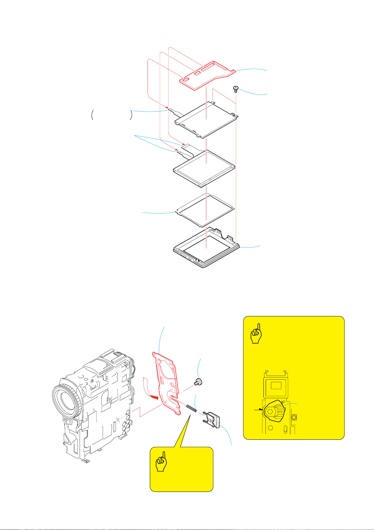
2-12. PD-193 BOARD
y
5
Back light
Cold cathode
fluorescent tube
4
Liquid crystal
indicator module
(6P)
(6P)
(24P)
PD-193
DCR-PC103E/PC104E/PC105/PC105E
6
PD-193 board
1
Two screws
(M1.7
lock ace, p2
×
2.5),
3
LCD panel protection sheet
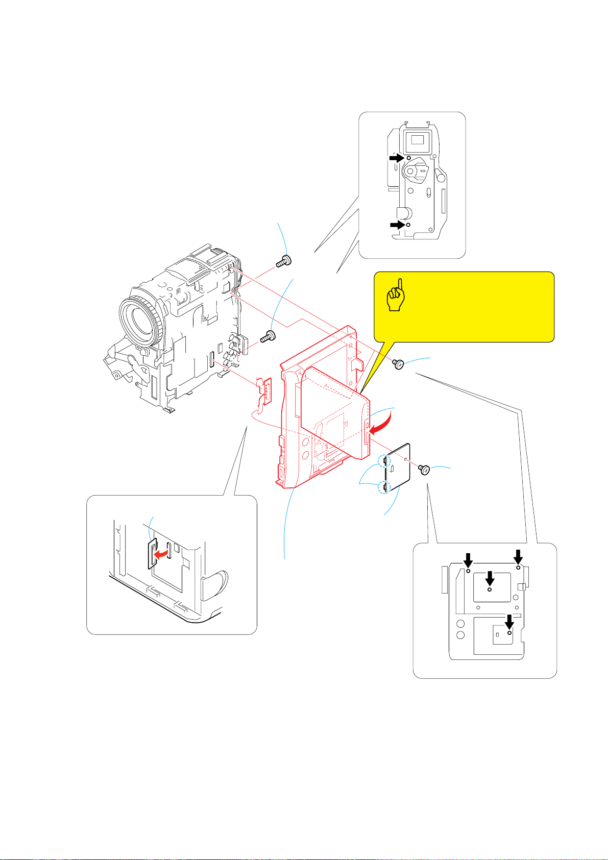
2-13. CABINET (REAR)
4
Remove the cabinet (rear)
in the direction of the arrow.
3
(M1.7 × 2.5),
lock ace, p2
2
Compression
spring
Screw
2
LCD cabinet (L) assembl
Caution
When installing the Cabinet (Rear),
install it while aligning the switch of the
Operation Switch Block (PS4400) with
the position A.
Control switch block
A
(PS4400)
Caution
Be careful not to drop
the compression coil.
2-11
1
Battery lock
DCR-PC103E/PC104E/PC105/PC105E
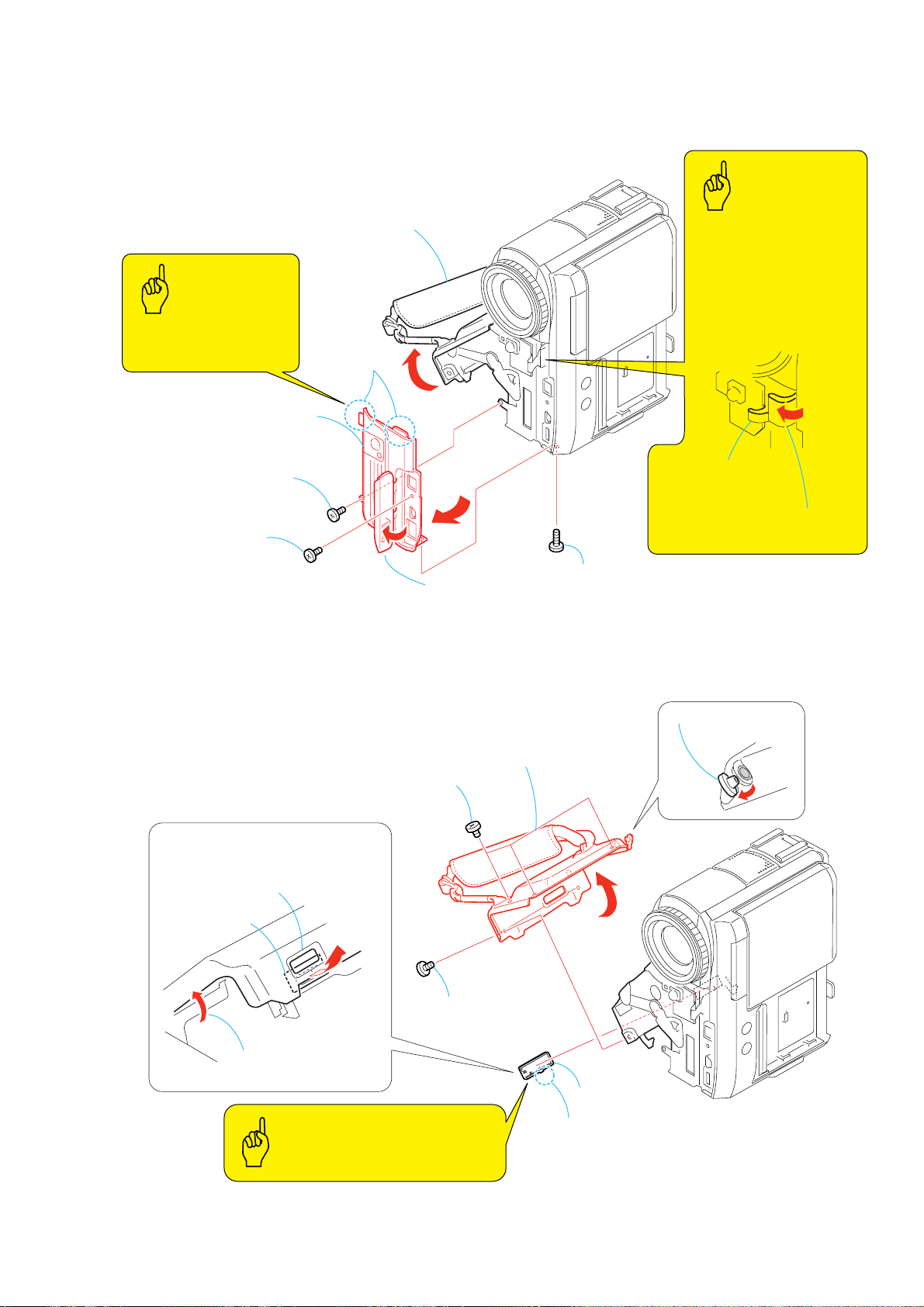
2-14. CONTROL SWITCH BLOCK (PS4400)
3
Control switch block
(PS4400)
1
Screw
(M1.7
lock ace, p2
2
Control switch block
(PS4400) (10P)
×
2.5),
G frame assembly
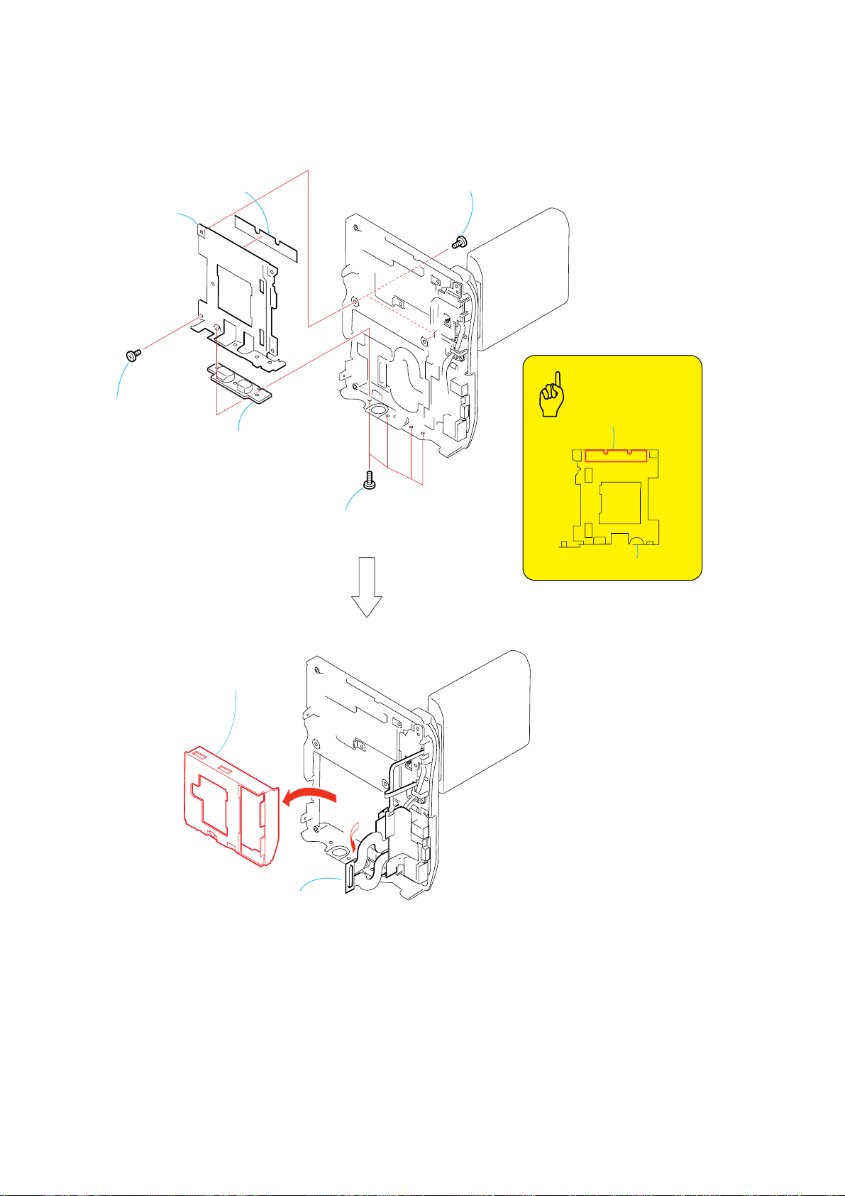
2-15. ST-084 BOARD (PC105/PC105E)
5
ST-084 board
Caution
If you install the Operation Switch
Block (PS4400) while the G Frame
Assy is left open, the open/close
switch will be broken. To install the
Operation Switch Block (PS4400),
be sure to install it after the G
Frame Assy is closed.
2
Condenser holder
Note: High-voltage cautions.
Control switch block (PS4400)
Open/close switch
Caution
(See page 1-2)
3
Flash unit (FL4400)
(19P)
4
ST-084 board (16P)
2-12
1
Screw
(M1.7
lock ace, p2
×
2.5),
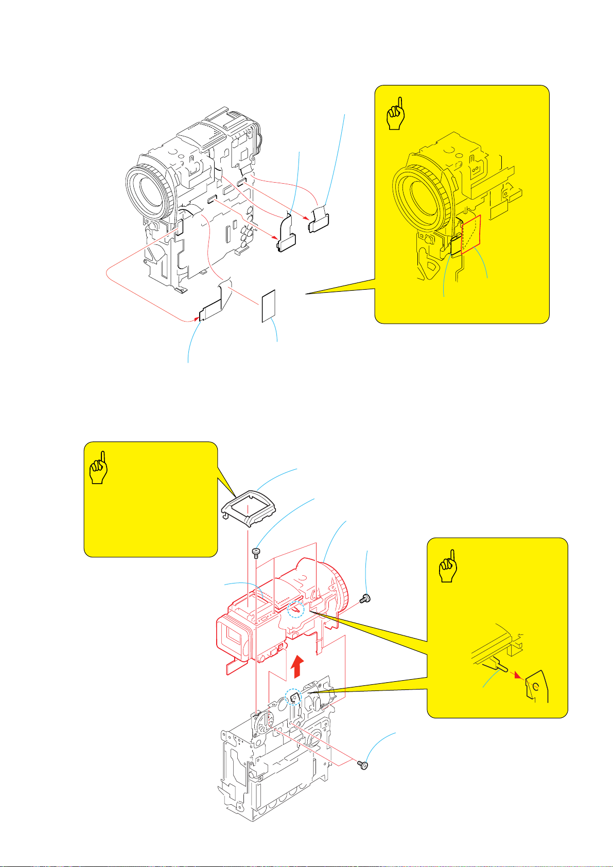
2-16. LENS/EVF/ST SECTION-1
4
(60P)
3
CD-444 board
(40P)
DCR-PC103E/PC104E/PC105/PC105E
VF-156 board
Caution
Lens fixed sheet
flexible board
(from the Lens device)
2
flexible board
(from the Lens device)
2-17. LENS/EVF/ST SECTION-2
Caution
When installing the cabinet
(upper), insert the cabinet (upper)
in straight down so that the rubber
of the Mic Unit shoud not be
deformed.
Rubber of the
Mic unit
1
Lens fixed sheet
3
Cabinet (upper)
4
lock ace, p2
Three screws (M1.7 × 2.5),
5
Lens/EVF/ST section
1
Screw
(M1.7
lock ace, p2
×
2.5),
Caution
To attach the Lens/EVF/ST section,
align the nightshot switch position
as shown.
2-13
2
Two screws
(M1.7
lock ace, p2
×
2.5),
Nightshot
switch
DCR-PC103E/PC104E/PC105/PC105E
2-18. EVF SECTION
2
Claw
4
Mic unit (6P)
3
FP-671 flexible board (10P)
5
EVF section
1
Dowel
2-14
2-19. VF-156 BOARD
y
DCR-PC103E/PC104E/PC105/PC105E
5
Two screws
(M1.7 × 2.5),
lock ace, p2
EVF section
2
Three claws
3
VF-156 board,
Connector retainer cushion
1
Two tapping screws
(M1.7 × 4)
6
VF fixed palate
4
Tapping screw
(M1.7 × 4)
7
guide assembly
9
LCD cushion
VF sleeve
0
w;
BL cushion L
qd
8
VF assembl
LCX032AN-5
qa
Two claws
qh
BL retainer
sheet metal
qk
BL cushion B
qj
Light guide plate block (0.44)
qg
VF-156 board
qf
Connector retainer cushion
ql
BL unit
qs
LCX032AN-5
(16P)
2-15
DCR-PC103E/PC104E/PC105/PC105E
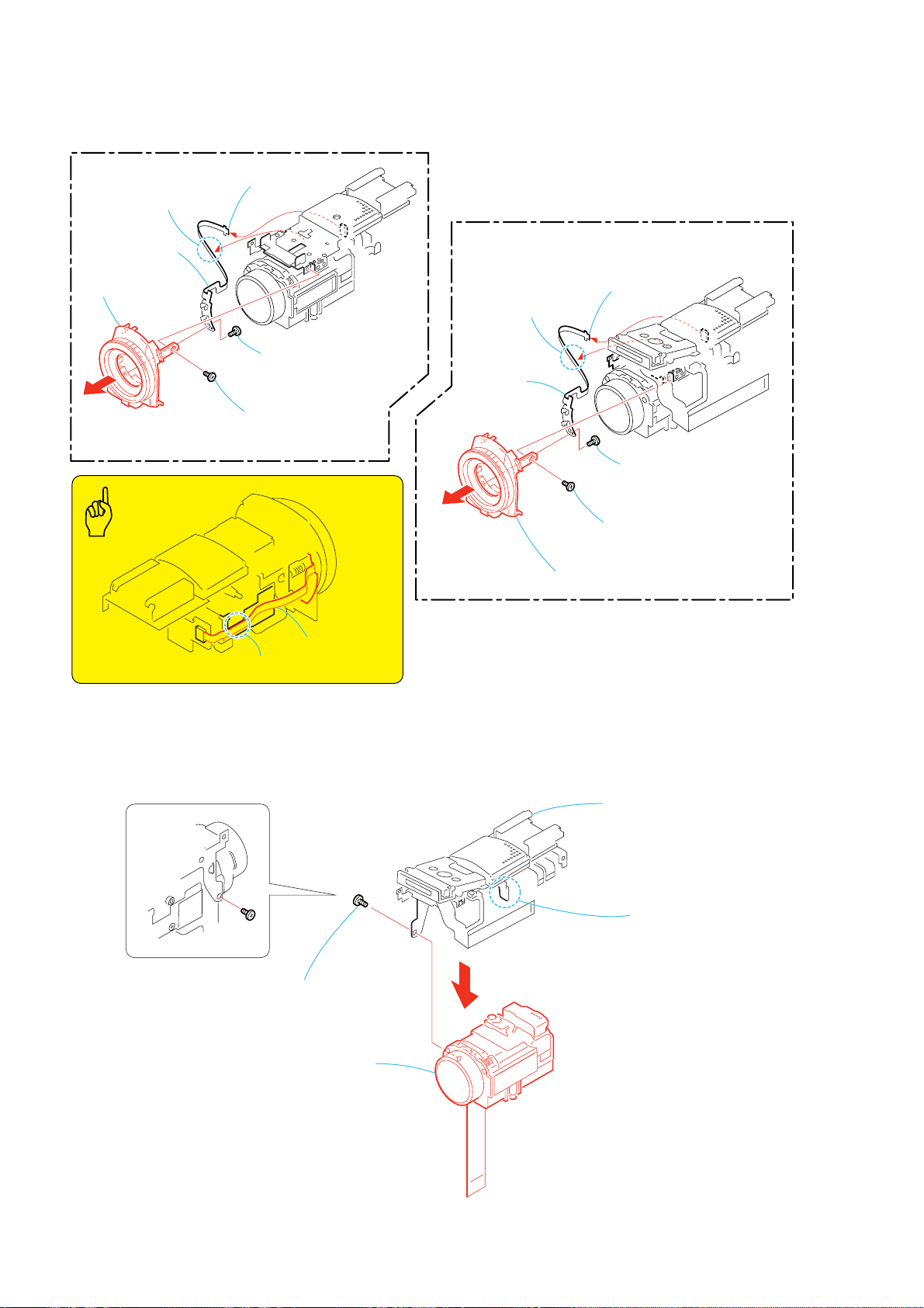
2-20. MF RING ASSEMBLY
(PC103E/PC104E)
3
Peel off the flexible
board that is attached
by adhesive agent.
5
FP-672 board
6
MF ring
assembly (N)
Caution
2
FP-672 board
(6P)
4
Screw
×
×
2.5),
(M1.7
lock ace, p2
1
Screw
(M1.7
lock ace, p2
2.5),
(PC105/PC105E)
3
Peel off the flexible
board that is attached
by adhesive agent.
5
FP-672
board
6
MF ring assembly
2
FP-672 board
(6P)
4
Screw
(M1.7
lock ace, p2
1
Screw
×
(M1.7
lock ace, p2
2.5),
×
2.5),
2-21.LENS SECTION
FP-672 board
Adhesive portion
1
Tapping screw
(M1.7
4
Lens section
3
Stroboscope section
2
Claw
×
4)
2-16
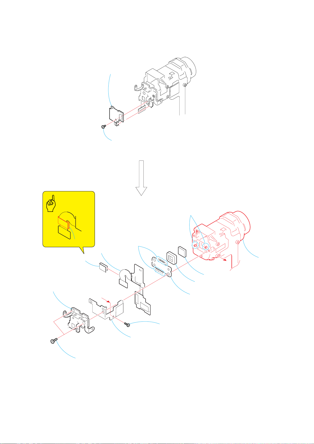
2-22.LENS DEVICE (LSV-751A)
2
CD-444 board
1
Screw
(M1.7
lock ace, p2
×
DCR-PC103E/PC104E/PC105/PC105E
2.5),
Caution
CD shield sheet
8
CD shield sheet
6
CD frame assembly
9
CD-444 board
A
qs
Remove the soldering
7
CD heat sink assembly
5
4
Tapping screw
(M1.7 × 4)
Two dowels
q;
qa
Seal rubber (W)
qd
CCD section
A
Optical filter block
qf
Lens device
(LSV-751A)
3
Two screws
(M1.7 × 8),
lock ace, p2
2-17
DCR-PC103E/PC104E/PC105/PC105E
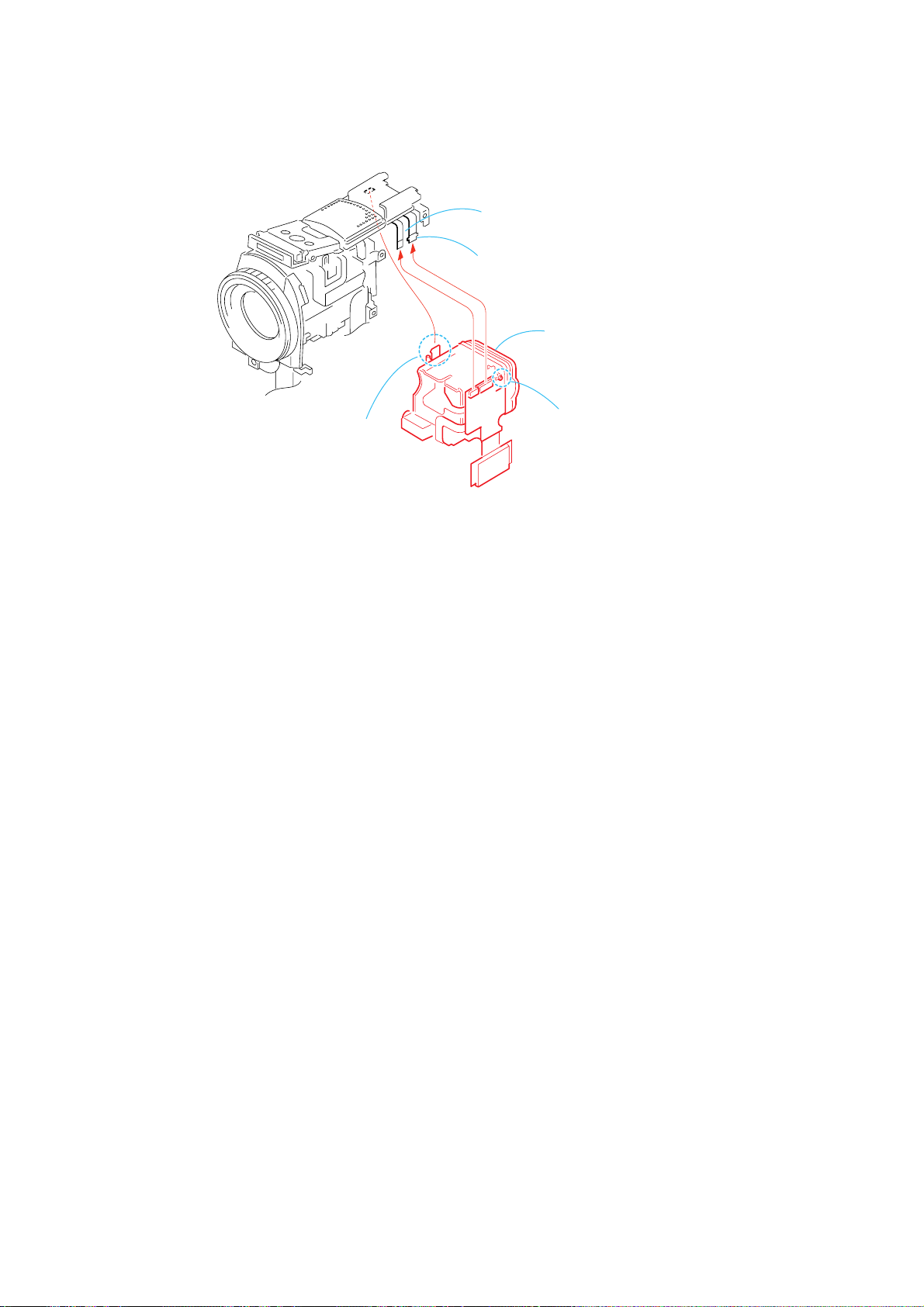
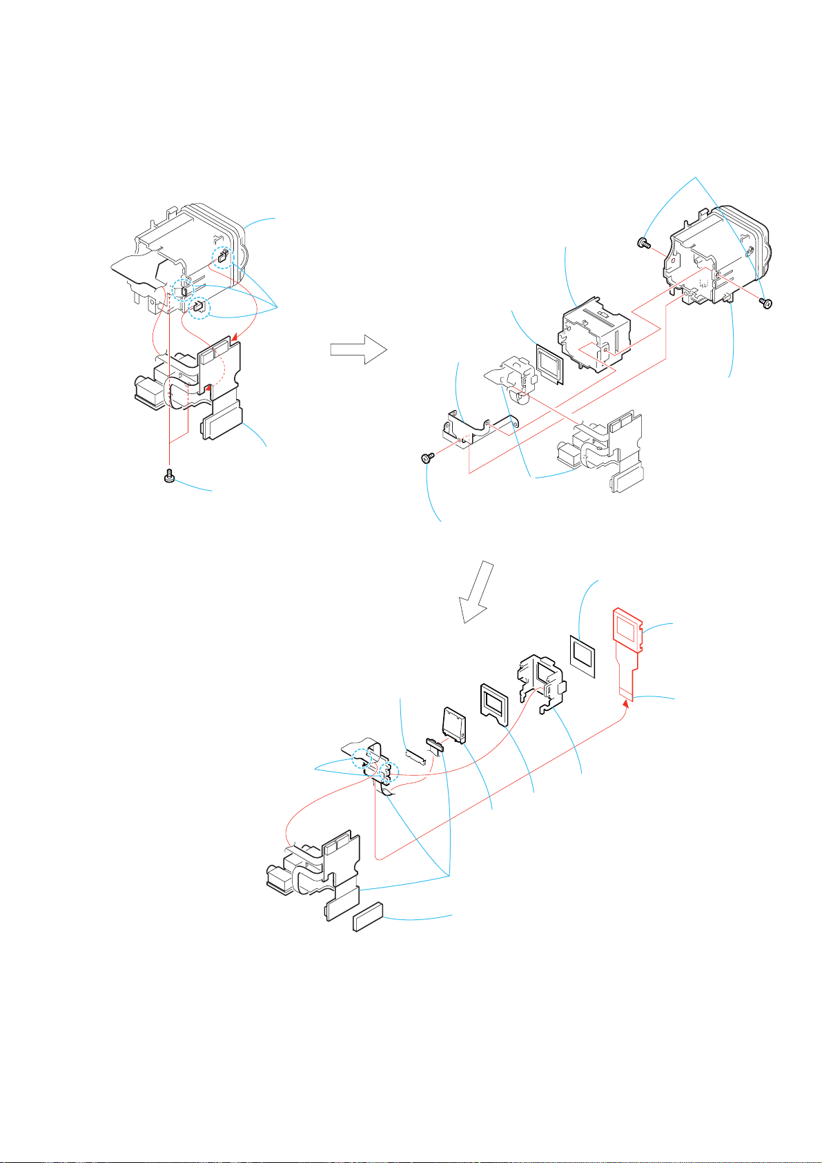
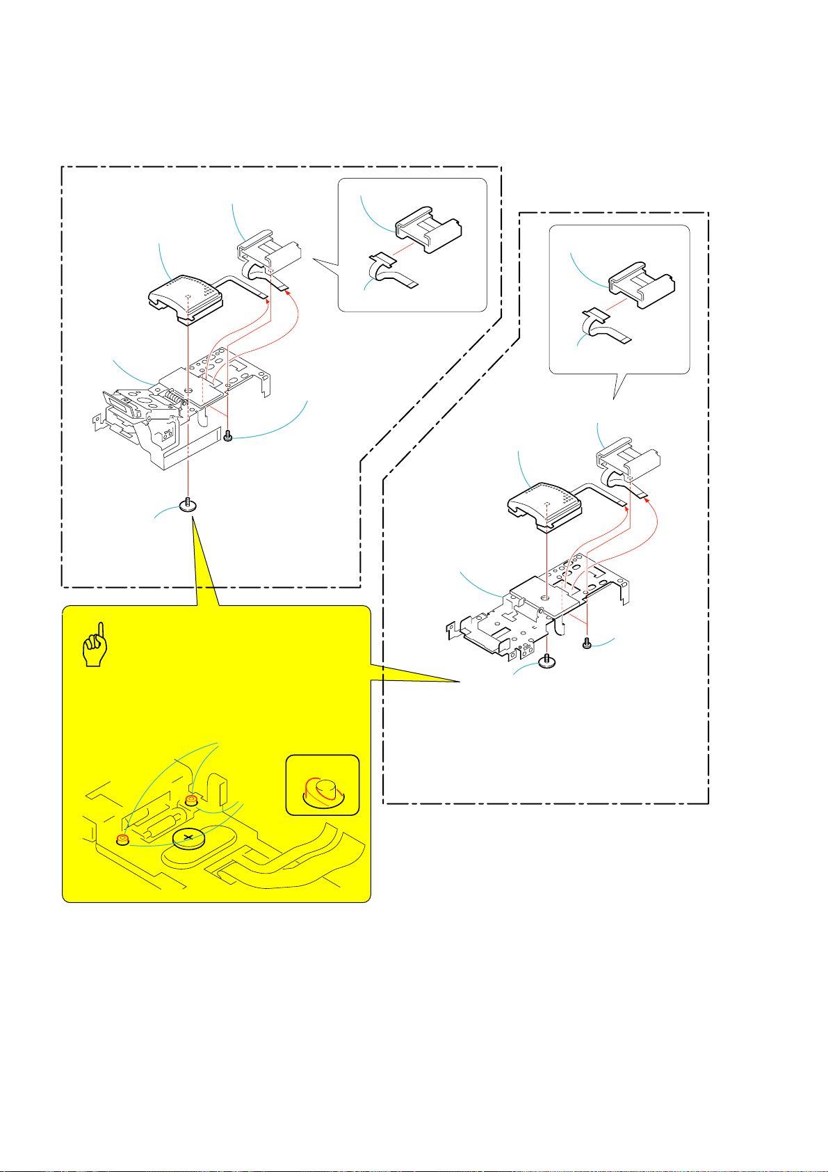
2-23. EXTERNAL CONNECTOR (HOT SHOE)
(PC105/PC105E)
2
External connector (hot shoe),
FP-671 flexible board
4
Mic unit
5
Stroboscope
section, ST frame
assembly
1
Two screws
(M1.7
lock ace, p2 (black)
7
External connector
(hot shoe)
6
FP-671 flexible board
×
2.5),
(PC103E/PC104E)
7
External connector
(hot shoe)
6
FP-671 flexible board
2
External connector (hot shoe),
FP-671 flexible board
3
Special tapping
screw
(M1.7
×
5.5)
Caution
When installing the Mic unit, align and insert the rubber
protrusions of the Mic unit into the hole of the FK frame
assembly so that the Mic unit made of rubber should
not be deformed.
Rubber protrusions
of the Mic unit
Hole of the
FK frame
assembly
NG
5
ST frame
assembly
3
screw
(M1.7
4
Mic unit
Special tapping
×
5.5)
1
Two screws
(M1.7
lock ace, p2
(black)
×
2.5),
2-18
 Loading...