

Sony DCR-PC1, DCR-PC1E Service Manual
DCR-PC1/PC1E
RMT-808/809
SERVICE MANUAL
Ver 1.0 1998. 07
D200 MECHANISM
DCR-PC1: NTSC model
DCR-PC1E: PAL model
Photo: DCR-PC1E
RMT-809
For MECHANISM ADJUSTMENTS, refer to the “DV MEHCANICAL
ADJUSTMENT MANUAL
supplement: 9-973-815-81) and “DV MECHANICAL ADJUSTMENT
MANUAL
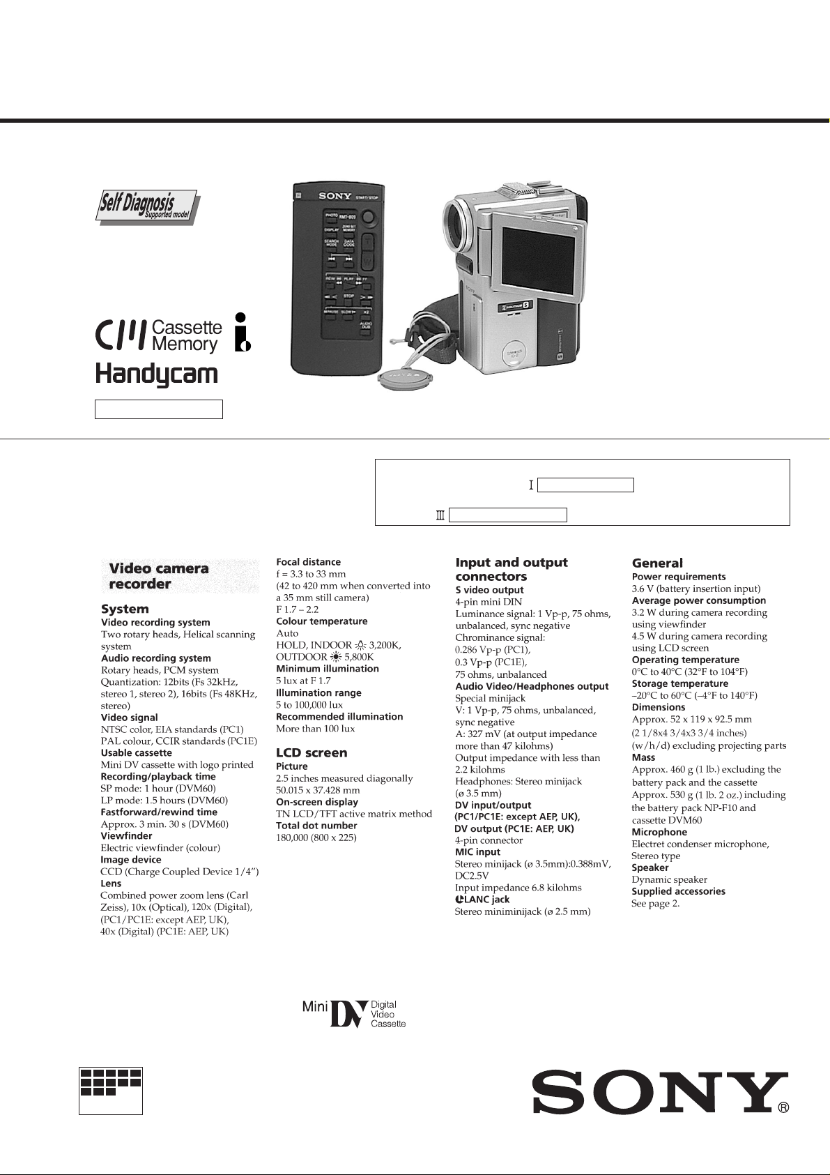
SPECIFICATIONS
D200 MECHANISM ” (original: 9-973-981-11).
US Model
Canadian Model
DCR-PC1
AEP Model
UK Model
Australian Model
Chinese Model
DCR-PC1E
E Model
Hong Kong Model
Tourist Model
DCR-PC1/PC1E
D MECHANISM ” (original: 9-973-815-11,
MICROFILM
— Continued on next page —
DIGITAL VIDEO CAMERA RECORDER
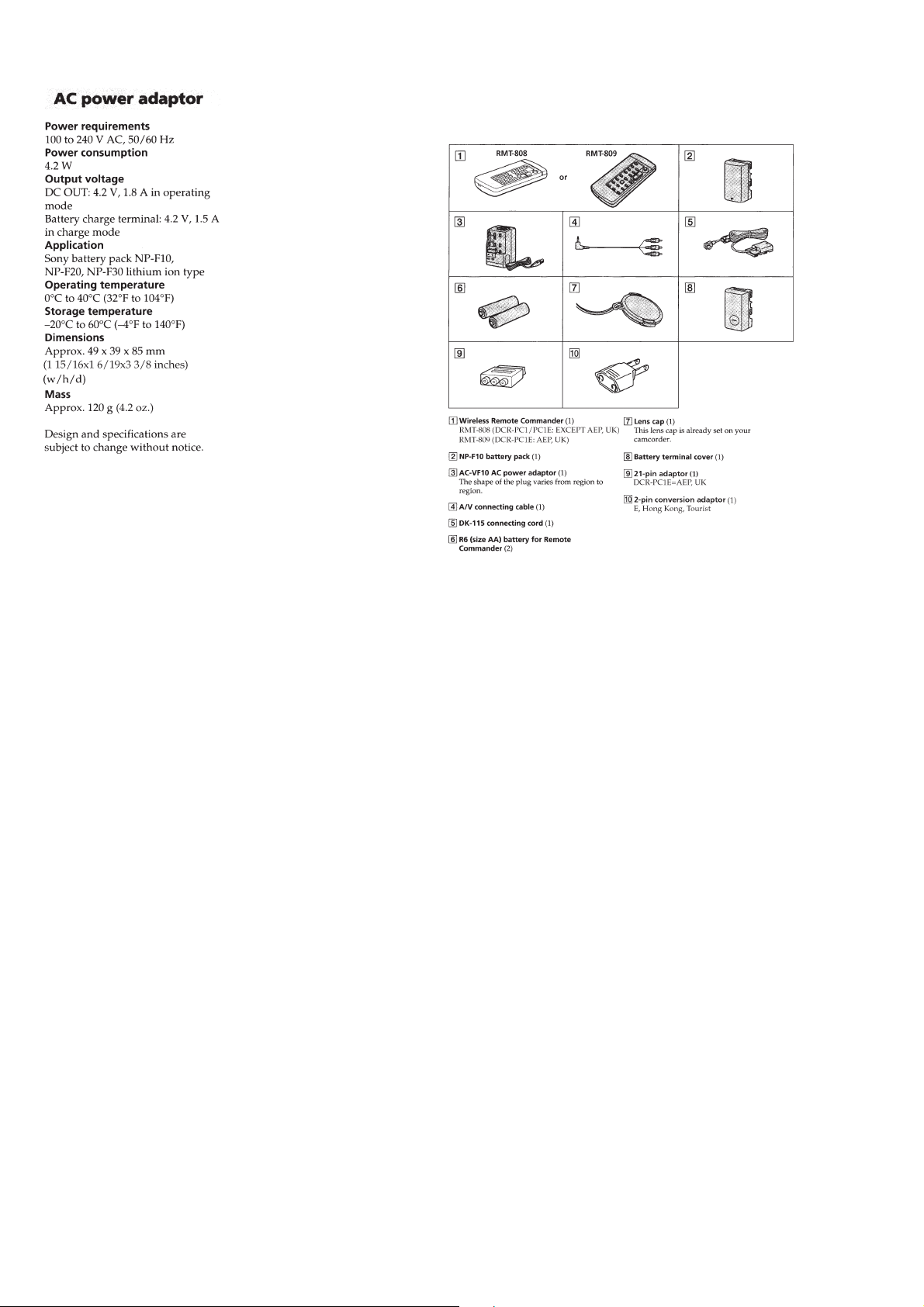
• SUPPLIED ACCESSORIES
Check that the following accessories are supplied with your
camcorder.
SAFETY-RELATED COMPONENT WARNING!!
COMPONENTS IDENTIFIED BY MARK ! OR DO TTED LINE WITH
MARK ! ON THE SCHEMATIC DIAGRAMS AND IN THE PARTS
LIST ARE CRITICAL TO SAFE OPERATION. REPLACE THESE
COMPONENTS WITH SONY PARTS WHOSE PART NUMBERS
APPEAR AS SHOWN IN THIS MANUAL OR IN SUPPLEMENTS
PUBLISHED BY SONY.
SAFETY CHECK-OUT
After correcting the original service problem, perform the following
safety checks before releasing the set to the customer.
1. Check the area of your repair for unsoldered or poorly-soldered
connections. Check the entire board surface for solder splashes
and bridges.
2. Check the interboard wiring to ensure that no wires are
"pinched" or contact high-wattage resistors.
3. Look for unauthorized replacement parts, particularly
transistors, that were installed during a previous repair . Point
them out to the customer and recommend their replacement.
ATTENTION AU COMPOSANT AYANT RAPPORT
À LA SÉCURITÉ!
LES COMPOSANTS IDENTIFÉS P AR UNE MARQUE ! SUR LES
DIAGRAMMES SCHÉMA TIQUES ET LA LISTE DES PIÈCES SONT
CRITIQUES POUR LA SÉCURITÉ DE FONCTIONNEMENT. NE
REMPLACER CES COMPOSANTS QUE PAR DES PIÈSES SONY
DONT LES NUMÉROS SONT DONNÉS DANS CE MANUEL OU
DANS LES SUPPÉMENTS PUBLIÉS PAR SONY.
4. Look for parts which, through functioning, show obvious signs
of deterioration. Point them out to the customer and
recommend their replacement.
5. Check the B+ voltage to see it is at the values specified.
6. Flexible Circuit Board Repairing
• Keep the temperature of the soldering iron around 270˚C
during repairing.
• Do not touch the soldering iron on the same conductor of the
circuit board (within 3 times).
• Be careful not to apply force on the conductor when soldering
or unsoldering.
— 2 —

TABLE OF CONTENTS
SERVICE NOTE
1. Power Supply During Repairs ············································ 5
2. How to Take a Cassette Out When the Main Power
Cannot Be Turned on·························································· 5
Trouble check ······································································1-26
Self-diagnosis function ························································1-27
Identifying the parts ·····························································1-28
Warning indicators ·······························································1-30
SELF-DIAGNOSIS FUNCTION
1. Self-Diagnosis Function ····················································· 6
2. Self-Diagnosis Display·······················································6
3. Service Mode Display ························································ 6
3-1. Display Method ·································································· 6
3-2. Switching of Backup No. ··················································· 6
3-3. End of Display ···································································· 6
4. Self-Diagnosis Code Table ················································· 7
1. GENERAL
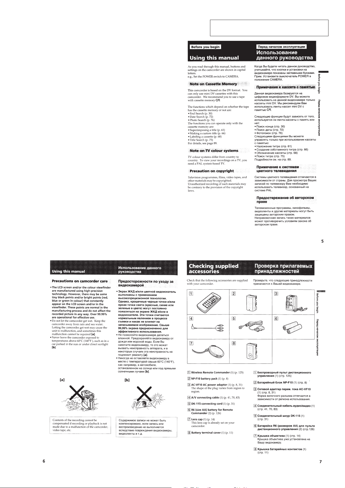
Before you begin
Using this manual ··································································1-1
Checking supplied accessories ··············································1-1
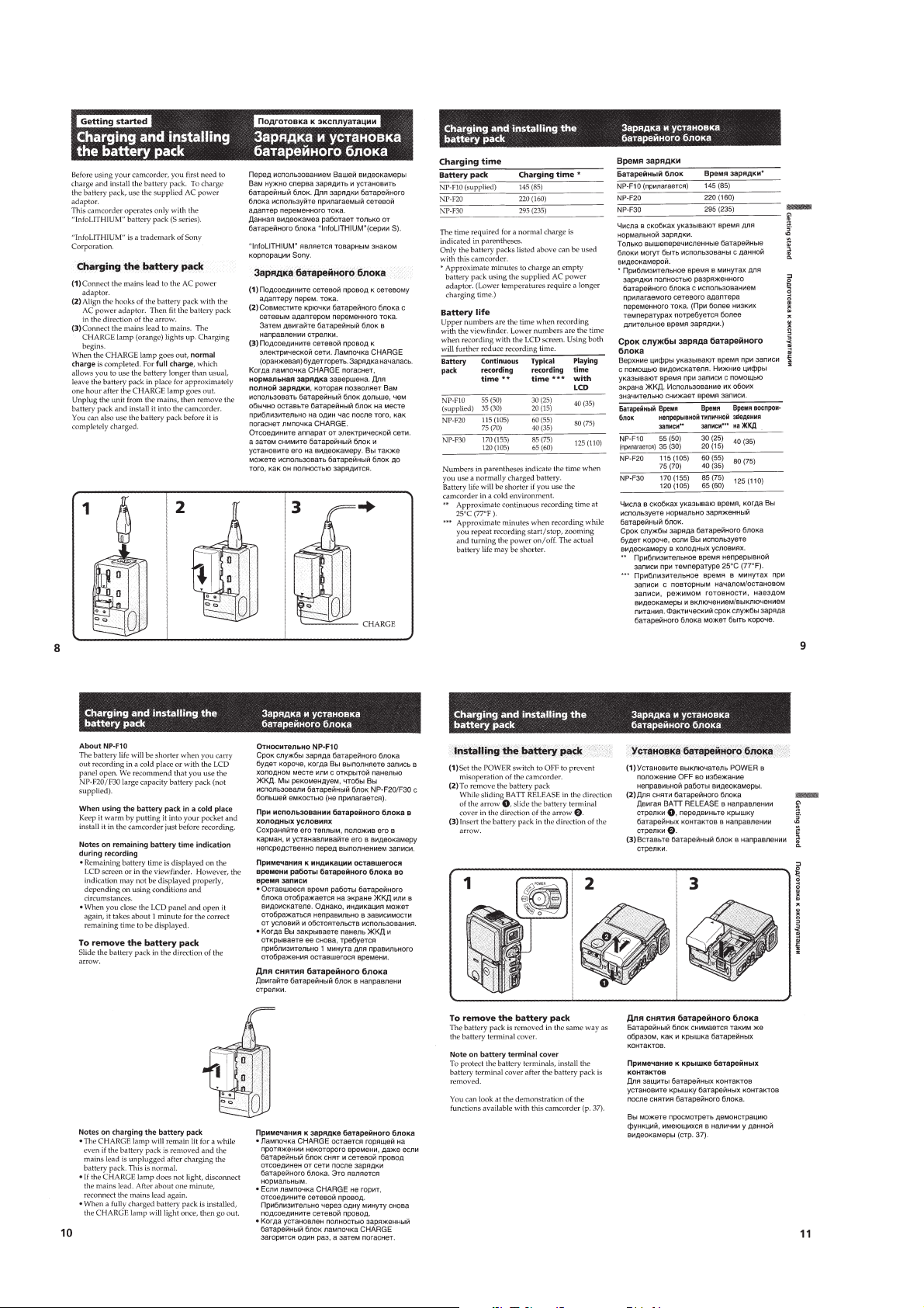
Getting started
Charging and installing the battery pack ·······························1-2
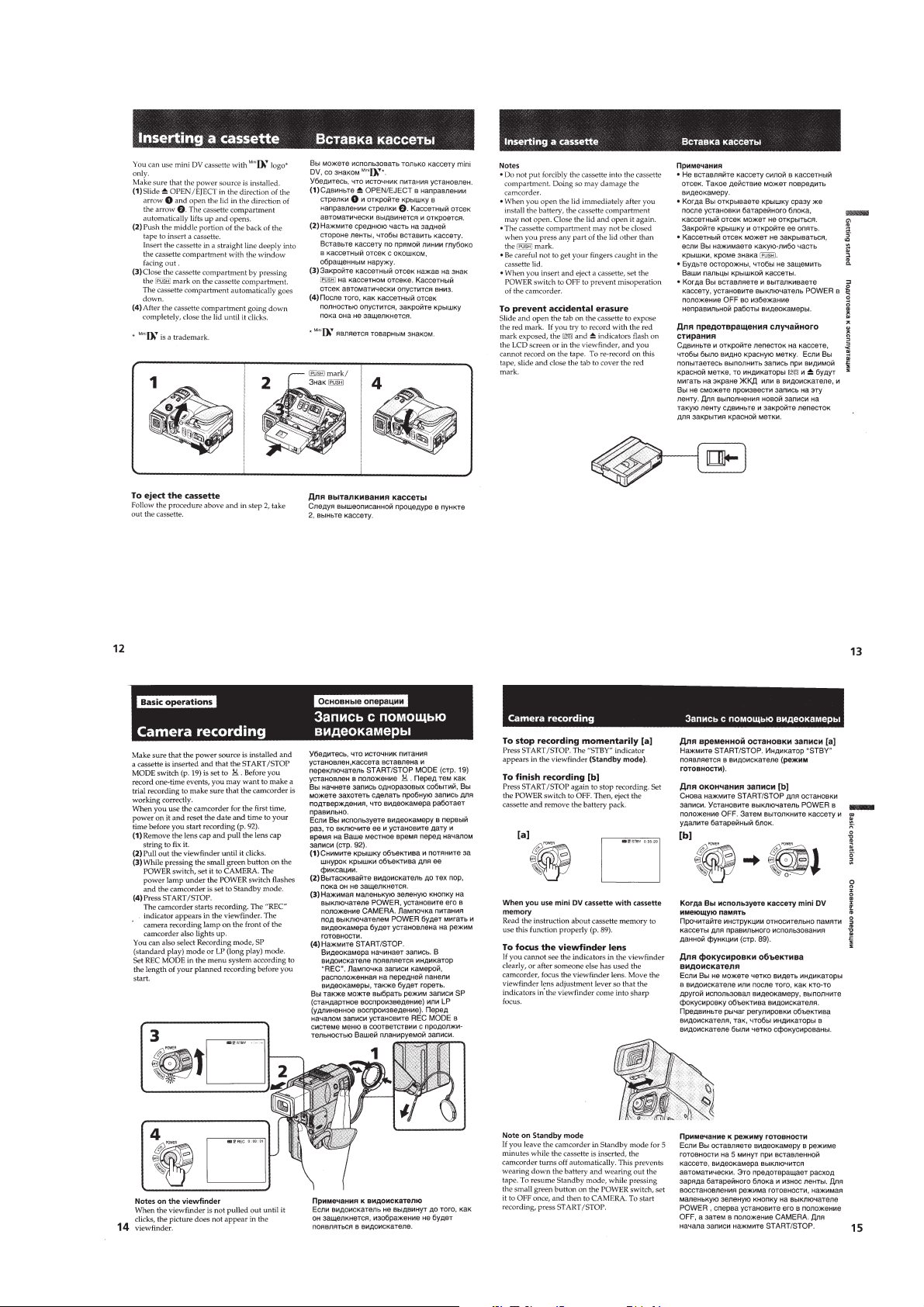
Inserting a cassette ·································································1-3
Basic operations
Camera recording···································································1-3
Hints for better shooting ························································1-5
Checking the recorded picture ···············································1-6
Playing back a tape ································································1-6
Searching for the end of the picture·······································1-7
Advanced operations
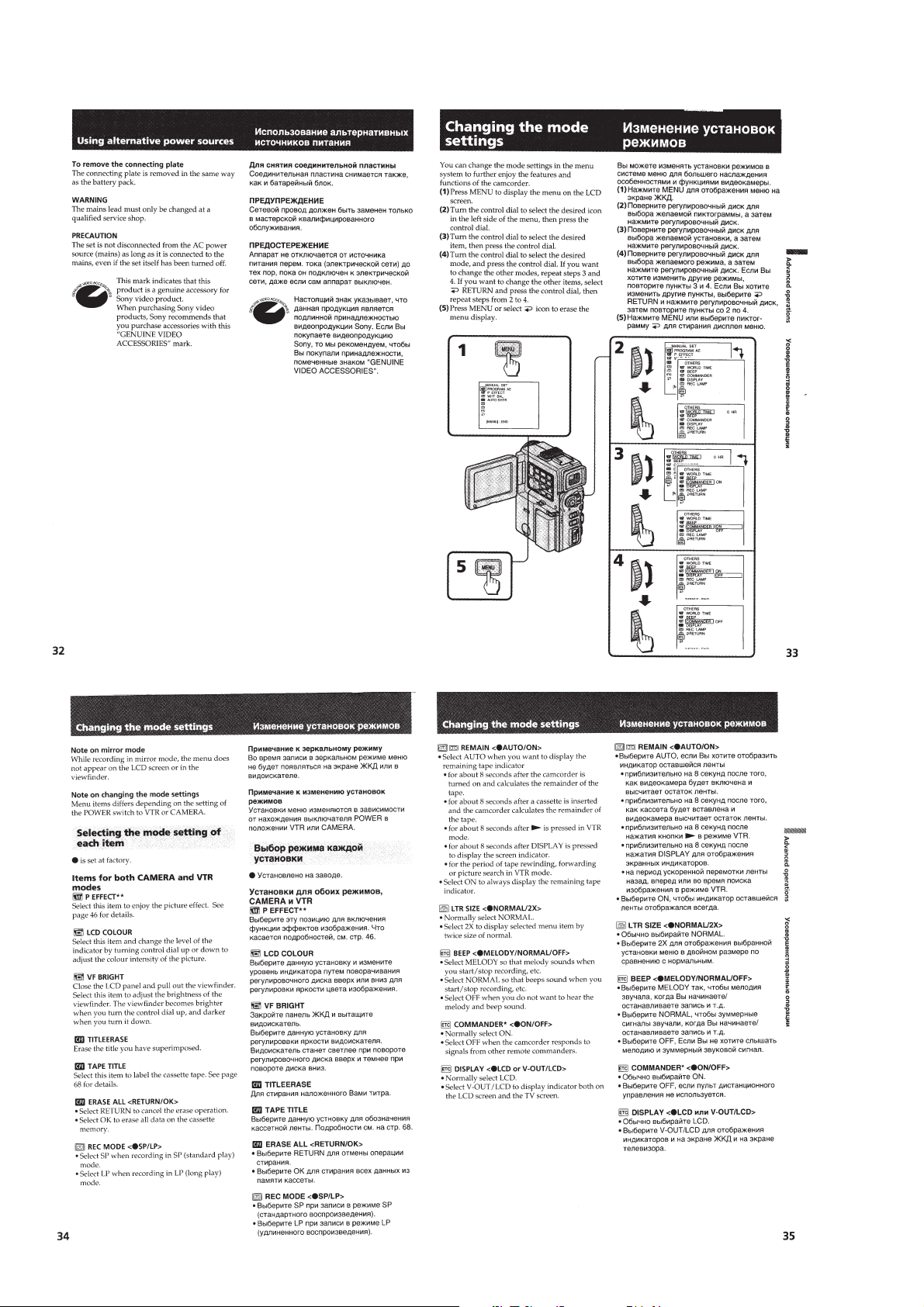
Using alternative power sources ············································1-7
Changing the mode setting ····················································1-8
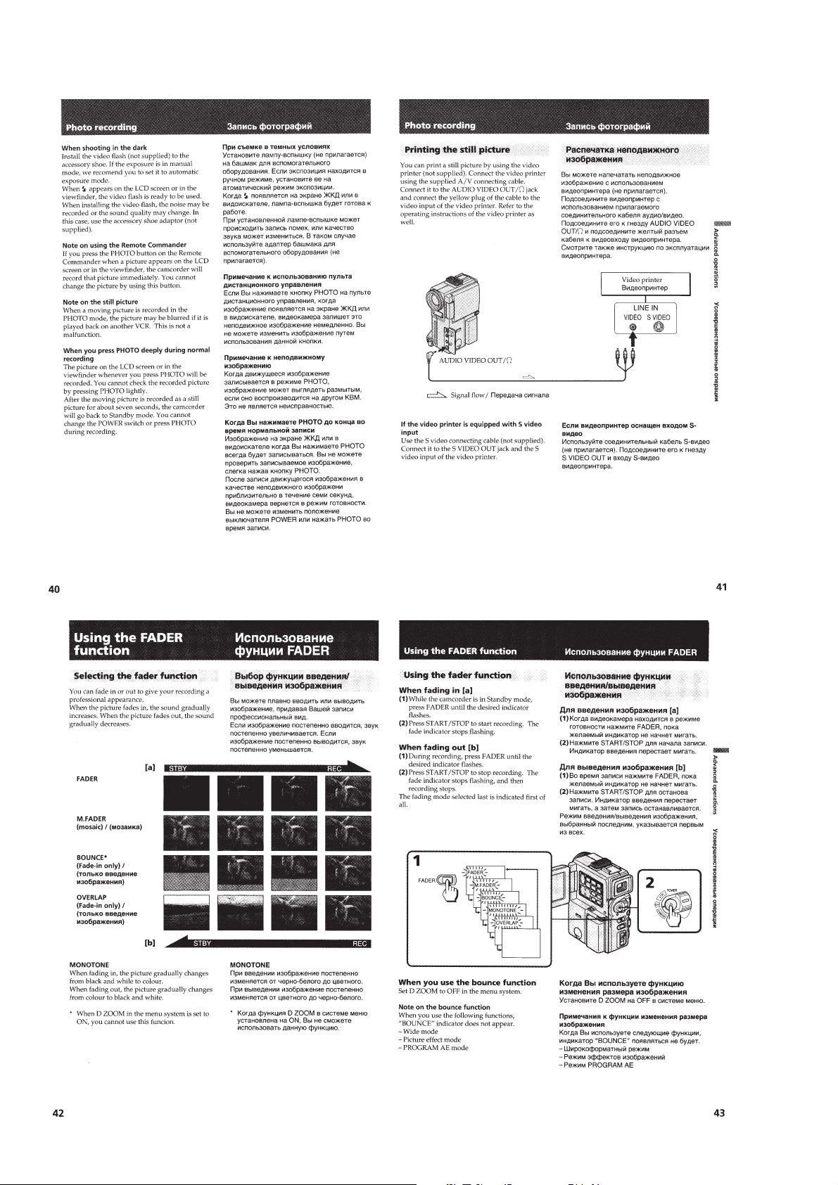
Photo recording······································································1-9
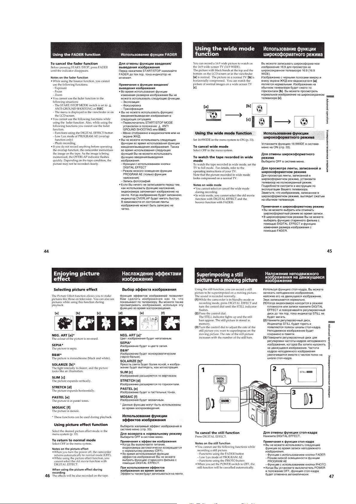
Using the FADER function ··················································1-10
Using the wide mode function ·············································1-11
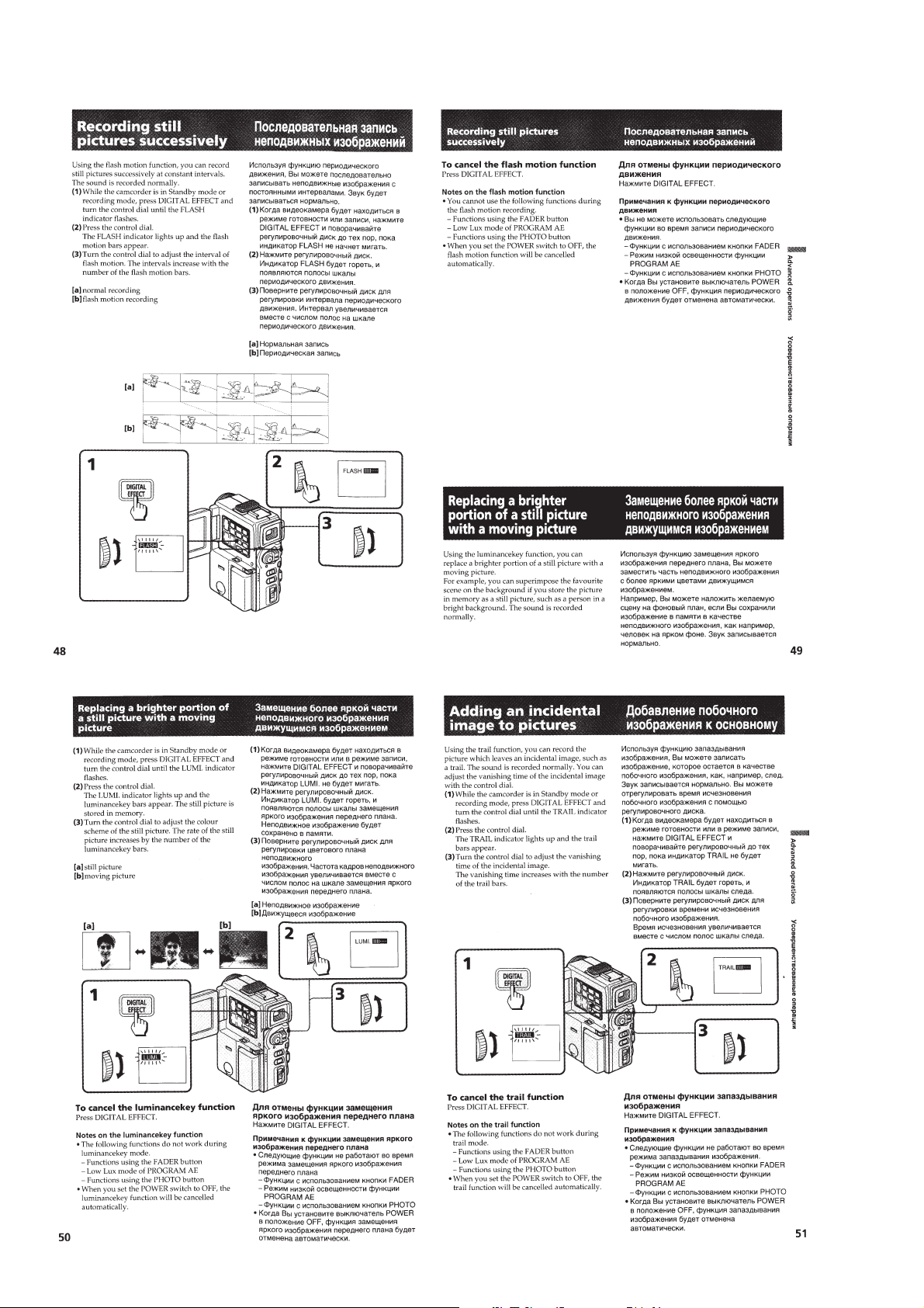
Enjoying picture effect·························································1-11
Superimposing a still picture on a moving picture ··············1-11
Recording still pictures successively ···································1-12
Replacing a brighter portion of a still picture with a
moving picture ·····································································1-12
Adding an incidental image to pictures ······························· 1-12
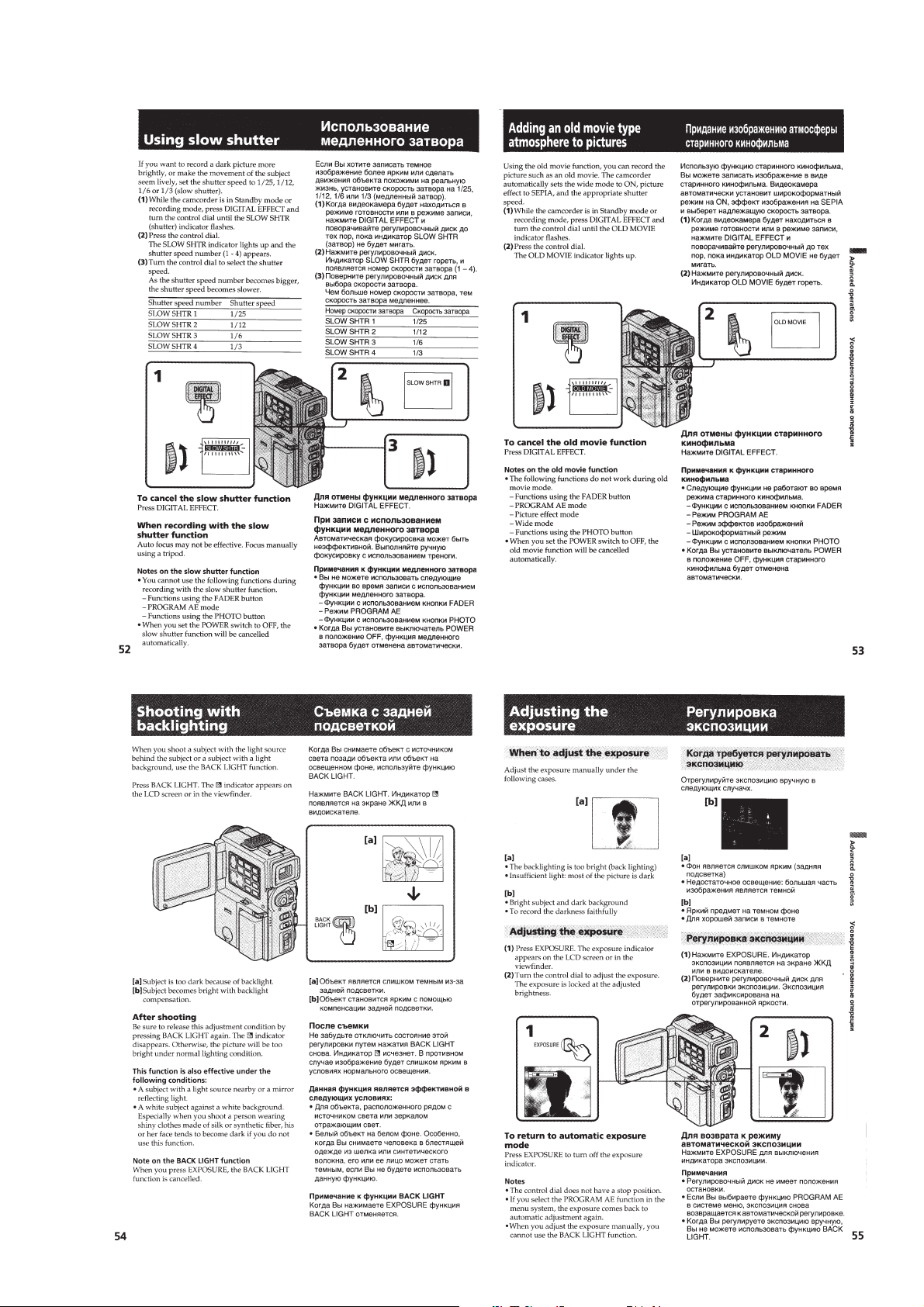
Using slow shutter ·······························································1-13
Adding an old movie type atmosphere to pictures ··············1-13
Shooting with backlighting··················································1-13
Adjusting the exposure ························································ 1-13
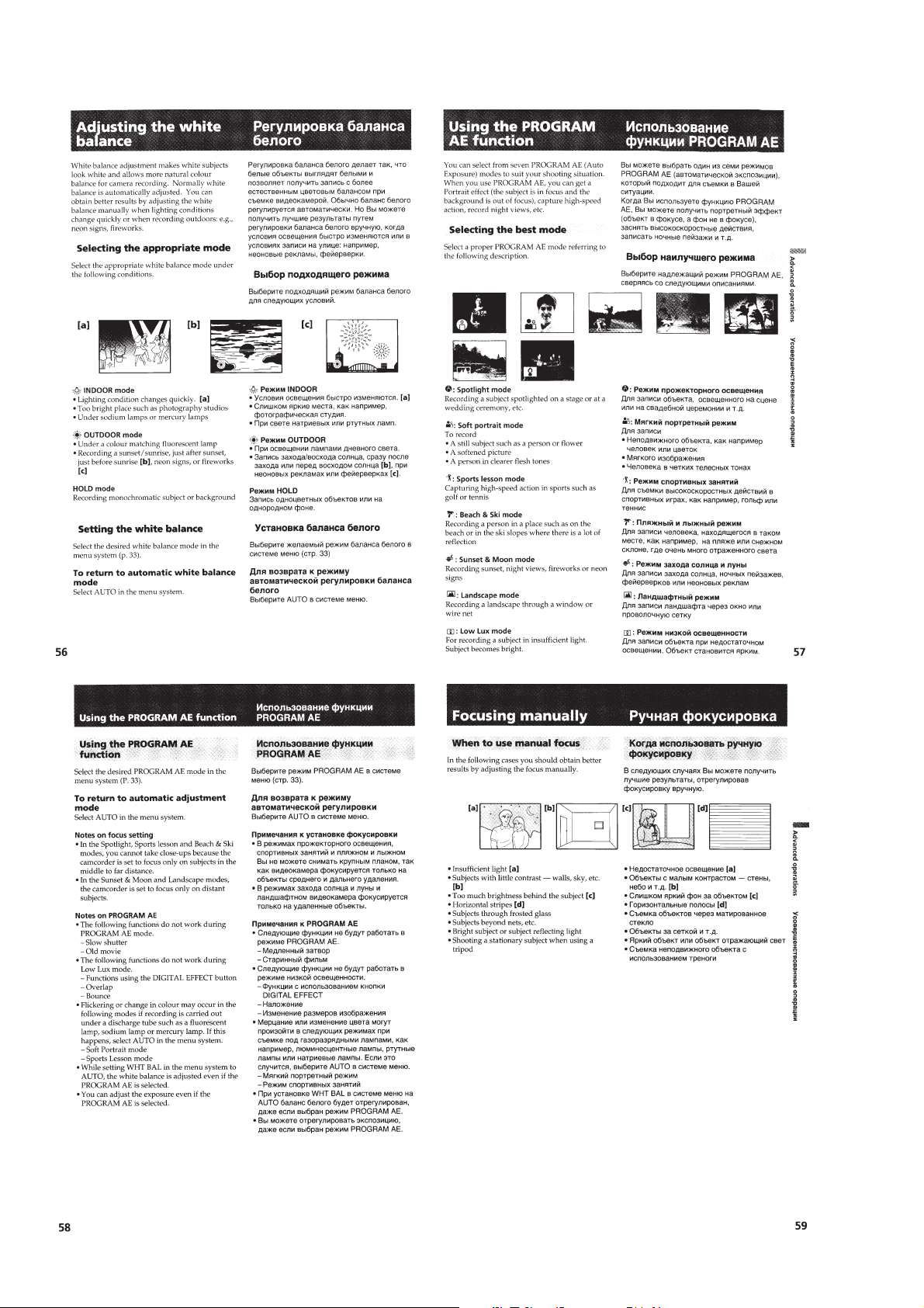
Adjusting the white balance·················································1-14
Using the PROGRAM AE function ·····································1-14
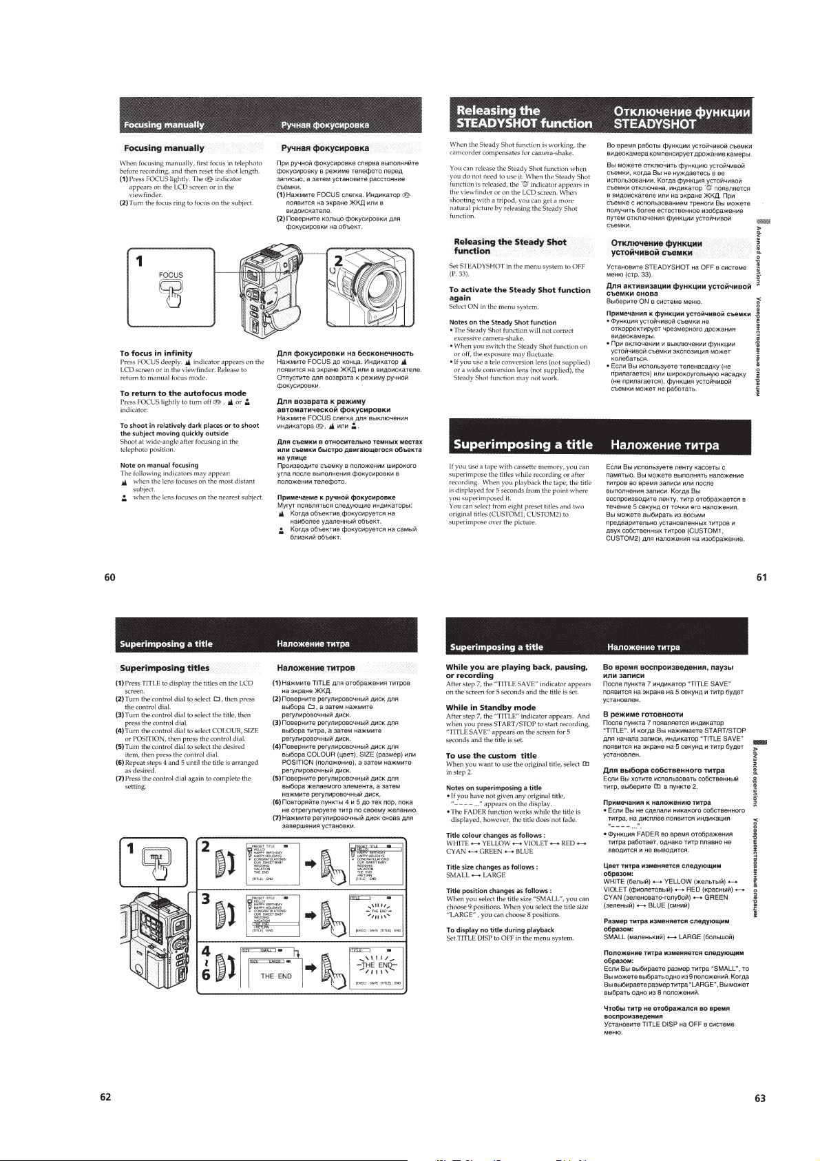
Focusing manually·······························································1-14
Releasing the STEADYSHOT function ······························ 1-15
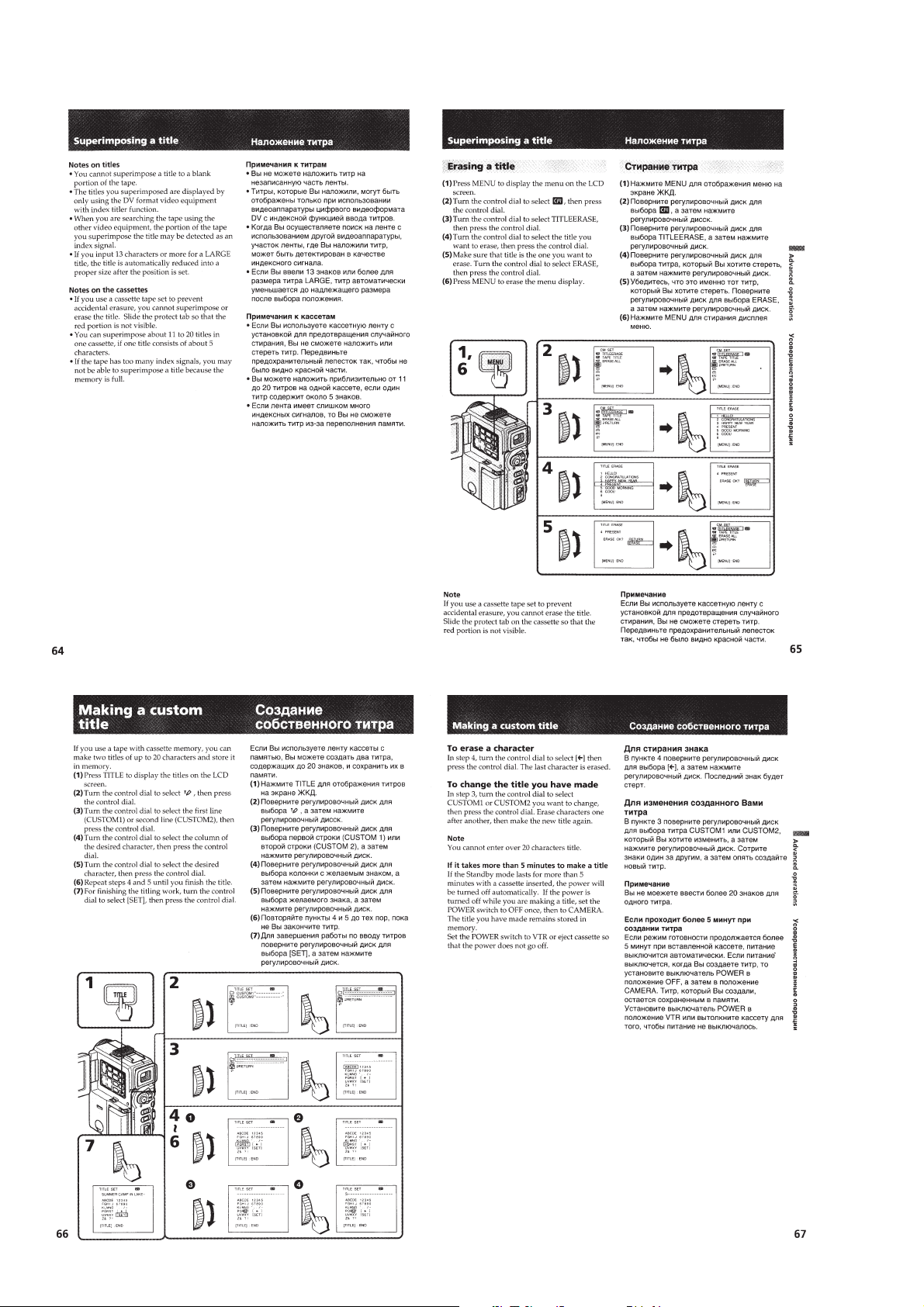
Superimposing a title ···························································1-15
Making a custom title ··························································1-16
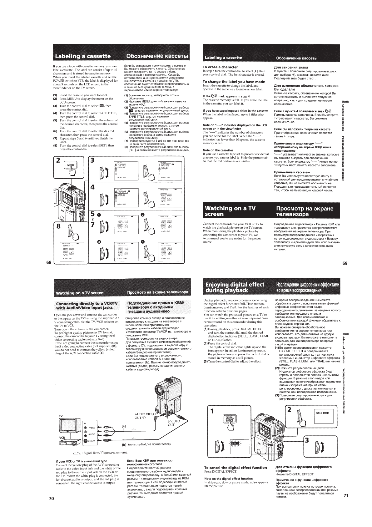
Labeling a cassette ·······························································1-17
Watching on a TV screen ·····················································1-17
Enjoying digital effect during playback·······························1-17
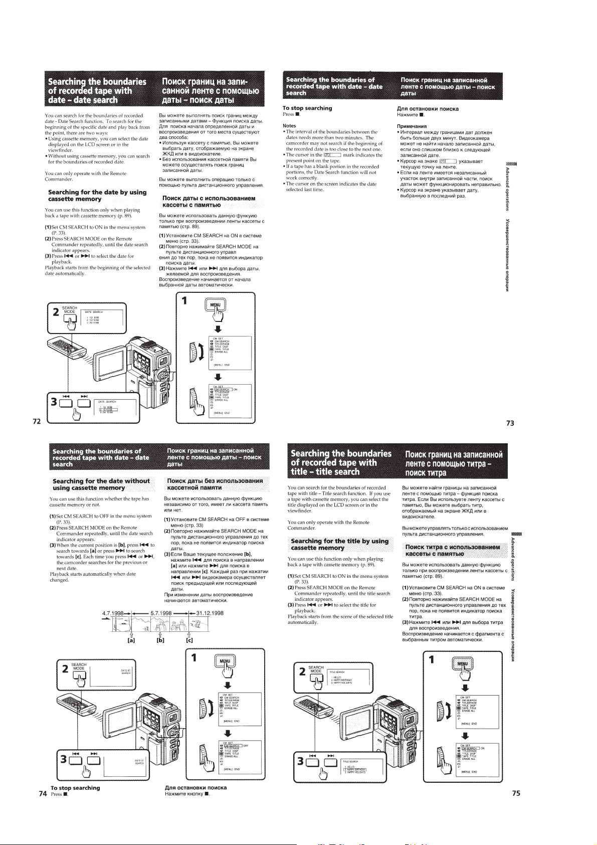
Searching the boundaries of recorded tape
with date - date search ·························································1-18
Searching the boundaries of recorded tape
with title - title search ·························································· 1-18
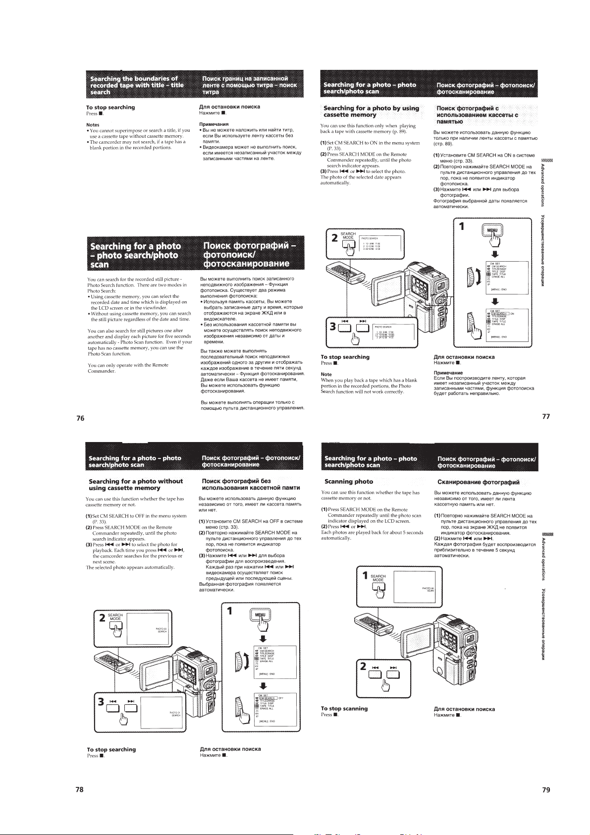
Searching for a photo - photo search/photo scan·················1-19
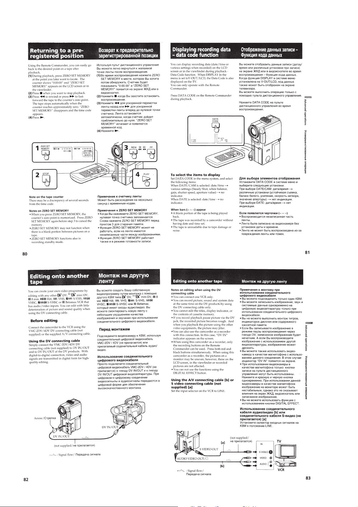
Returning to a preregistered position··································· 1-20
Displaying recording data - data code function ···················1-20
Editing onto another tape·····················································1-20
Replacing recording on a tape - insert editing ·····················1-21
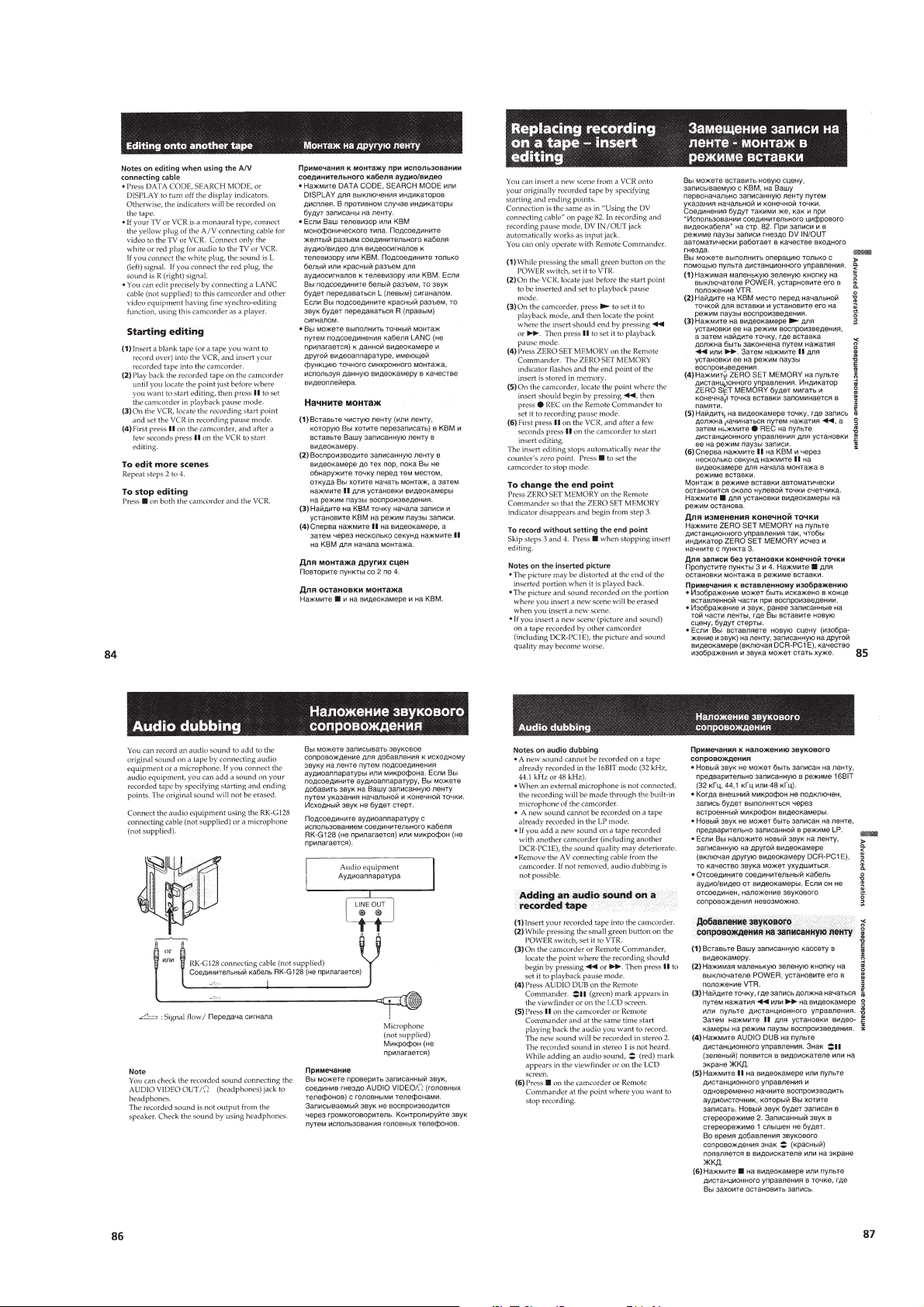
Audio dubbing ·····································································1-21
Additional information
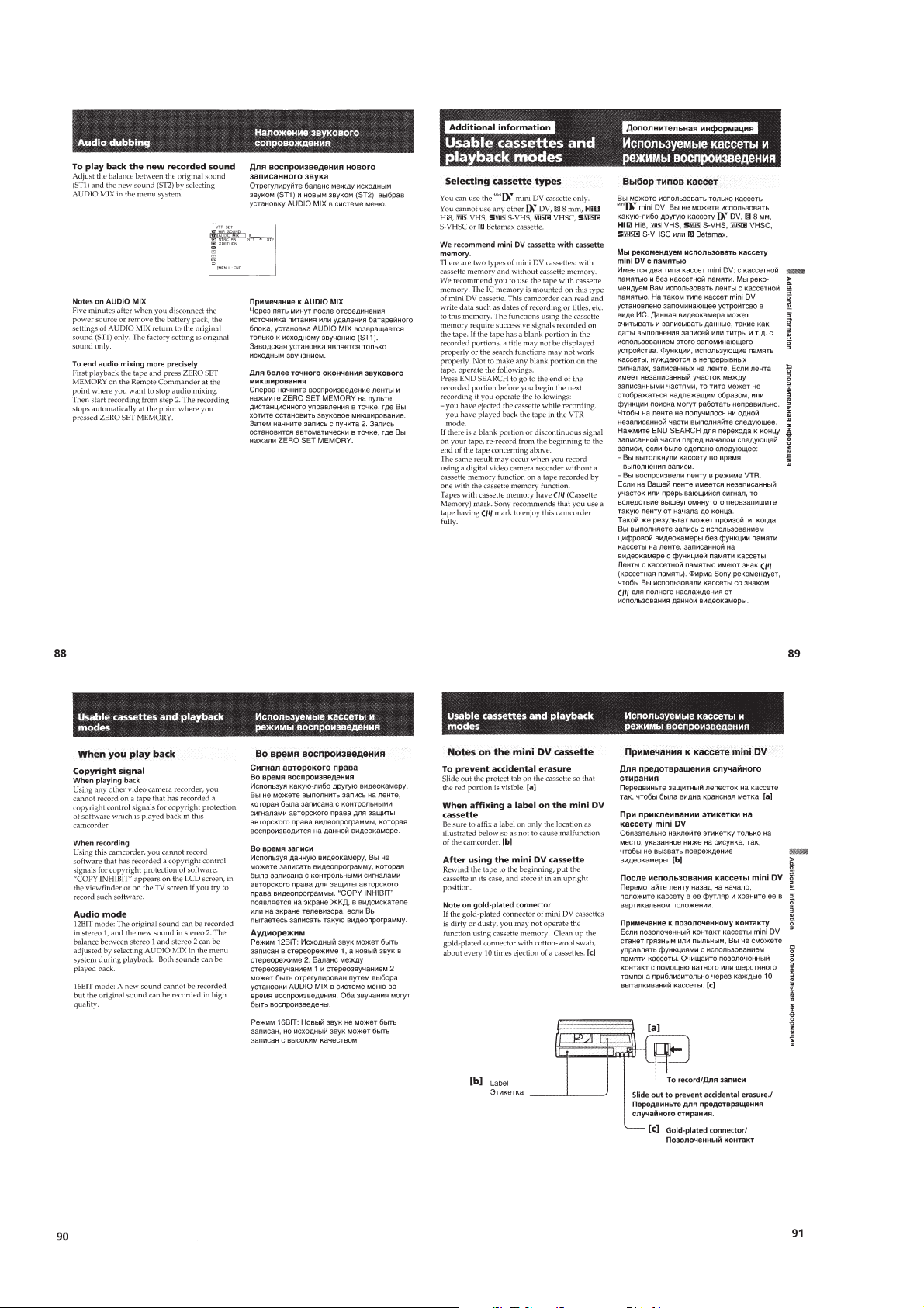
Usable cassettes and playback modes··································1-22
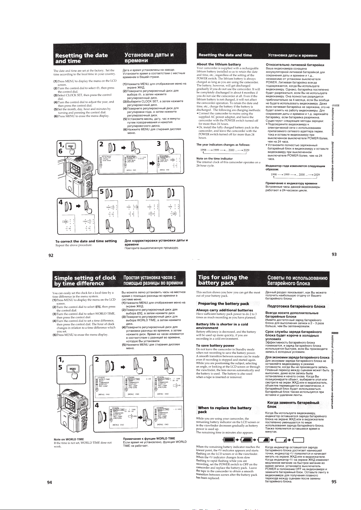
Resetting the date and time··················································1-23
Simple setting of clock by time difference ··························1-23
Tips for using the battery pack ············································1-23
Maintenance information and precautions···························1-24
Using your camcorder abroad·············································· 1-26
2. DISASSEMBLY
2-1. Cabinet (L) Assembly, Cabinet (R) Assembly ················2-1
2-2. Cabinet (L) Assembly, EVF, MD Block Assembly ·········2-2
2-3. VC-210 Board, DC-111 Board, MF-40 Board ················2-2
2-4. Control Switch Block ······················································2-3
2-5. Cabinet (R) Assembly, PD-102 Board ····························2-4
2-6. CD-203 Board ·································································2-5
2-7. VF-125 Board ··································································2-5
2-8. Service Position (Mainly for Adjustment)·······················2-6
2-9. Service Position (Mainly for Voltage Measurement) ······2-6
2-10. Circuit Boards Location ··················································2-7
2-11. Flexible Boards Location ················································ 2-8
3. BLOCK DIAGRAMS
3-1. Overall Block Diagram ···················································3-1
3-2. Power Block Diagram ·····················································3-5
4. PRINTED WIRING BOARDS AND
SCHEMATIC DIAGRAMS
4-1. Frame Schematic Diagram ··············································4-1
4-2. Printed Wiring Boards and Schematic Diagrams ············4-5
• CD-203 (CCD Imager) Printed Wiring Board············· 4-7
• CD-203 (CCD Imager) Schematic Diagram ···············4-9
• VC-210 (Camera Process, Mecha SP Control,
Blocking, Camera Hi Control, Audio Processor,
EVF Driver, DC/DC Converter, Line Out Amp)
Printed Wiring Board ····································4-12
• VC-210 (Camera Process)(1/8)
Schematic Diagram ·······································4-19
• VC-210 (Mecha SP Control)(2/8)
Schematic Diagram ·······································4-23
• VC-210 (Blocking)(3/8)
Schematic Diagram ·······································4-27
• VC-210 (Camera Hi Control)(4/8)
Schematic Diagram ·······································4-31
• PR-31 (Panel SW) Printed Wiring Board ··················4-34
• VC-210 (Audio Processor)(5/8)
Schematic Diagram ·······································4-37
• VC-210 (EVF Driver)(6/8)
Schematic Diagram ·······································4-39
• VC-210 (DC/DC Converter)(7/8)
Schematic Diagram ·······································4-43
• VC-210 (Line Out Amp)(8/8)
Schematic Diagram ·······································4-45
• MR-40 (Drum/Capstan Drive, REC/PB Head Amp)
Printed Wiring Board ····································4-48
• MR-40 (Drum/Capstan Drive)(1/2)
Schematic Diagram ·······································4-51
• MR-40 (REC/PB Head Amp)(2/2)
Schematic Diagram ·······································4-54
• PD-102 (RGB Driver)(1/2)
Schematic Diagram ·······································4-57
• PD-102 (Timing Generator)(2/2)
Schematic Diagram ·······································4-61
• PD-102 (RGB Driver, Taming Generator)
Printed Wiring Board ····································4-63
• VF-125 (Back-Light Driver)
Printed Wiring Board ····································4-65
• VF-125 (Back-Light Driver)
Schematic Diagram ·······································4-67
• Control Switch Block (FK-4780)
Schematic Diagram ·······································4-68
• TB-37 (Battery Terminal) Printed Wiring Board·······4-71
— 3 —

• DD-111 (DC/DC Converter)
Printed Wiring Board ····································4-72
• DD-111 (DC/DC Converter)
Schematic Diagram ·······································4-75
5. ADJUSTMENTS
5-1. Camera Section Adjustment ············································5-1
1-1. Preparations before Adjustment (Camera Section) ········· 5-1
1-1-1.List of Service Tools ························································5-1
1-1-2.Preparations ·····································································5-2
1-1-3.Precaution ········································································5-4
1. Setting the Switch···························································· 5-4
2. Order of Adjustments ······················································5-4
3. Subjects ···········································································5-4
1-2. Initialization of F, E Page Data········································5-5
1. Initializing the F, E Page Data ·········································5-5
2. Modification of F, E Page Data ······································· 5-5
3. F Page Table ····································································5-5
4. E Page table ·····································································5-8
1-3. Camera System Adjustments··········································· 5-9
1. 36 MHz Origin Oscillation Adjustment
(VC-210 board) ·······························································5-9
2. HALL Adjustment ···························································5-9
3. Flange Back Adjustment ···············································5-10
3-1. Flange Back Adjustment (1)··········································5-10
3-2. Flange Back Adjustment (2)··········································5-10
4. Flange Back Check························································5-11
5. Optical Axis Adjustment ···············································5-12
6. Picture Frame Setting ····················································5-13
7. AGC Gain Calibration Adjustment ·······························5-13
8. Color Reproduction Adjustment····································5-14
9. MAX GAIN Adjustment ···············································5-15
10. Auto White Balance & LV Standard Data Input ···········5-15
11. Auto White Balance Adjustment ···································5-16
12. White Balance Check ····················································5-16
13. Angular Velocity Sensor Sensitivity Adjustment ··········5-17
1-4. Color Electronic Viewfinder System Adjustment··········5-18
1. VCO Adjustment (VC-210 board) ································ 5-18
2. Bright Adjustment (VC-210 board)·······························5-19
3. Contrast Adjustment (VC-210 board) ···························5-19
4. White Balance Adjustment (VC-210 board) ·················5-20
1-5. LCD System Adjustment···············································5-21
1. VCO Adjustment (PD-102 board)································· 5-21
2. Black Limit Adjustment (PD-102 board) ······················5-22
3. Bright Adjustment (PD-102 board) ·······························5-22
4. Gamma-1 Adjustment (PD-102 board) ·························5-23
5. Contrast Adjustment (PD-102 board)····························5-23
6. Center Level Adjustment (PD-102 board)·····················5-24
7. White Balance Adjustment (PD-102 board)··················5-24
5-2. Mechanism Section Adjustment ····································5-25
2-1. How to Enter Record Mode without Cassette ··············5-25
2-2. How to Enter Playback Mode without Cassette ···········5-25
2-3. Tape Path Adjustment ····················································5-25
1. Preparation for Adjustment ··········································· 5-25
2. Procedure after Operations ············································5-25
5-3. Video Section Adjustments ···········································5-26
3-1. Preparation before Adjustments ····································5-26
3-1-1.Equipment Required ······················································5-26
3-1-2.Precaution on Adjusting ················································5-27
3-1-3.Adjusting Connectors ····················································5-27
3-1-4.Connecting the Equipment ············································5-28
3-1-5.Alignment Tapes····························································5-28
3-1-6.Output Level and Impedance·········································5-28
3-2. Initialization of C, D Page Data ···································· 5-29
1. Initializing the C Page Data···········································5-29
2. Modification of C Page Data·········································5-29
3. C Page Table ··································································5-29
4. Initializing the D Page Data ··········································5-32
5. Modification of D Page Data·········································5-32
— 4 —
6. D Page Table·································································· 5-32
3-3. System Control System Adjustment······························5-34
1. Battery End Adjustment (VC-210 board)······················5-34
3-4. Servo and RF System Adjustment·································5-35
1. Cap FG Duty Adjustment (MR-40 board)·····················5-35
2. T-reel FG Duty Adjustment (MR-40 board)··················5-35
3. PLL f
0 & LPF f0 Adjustment (MR-40 board)················5-35
4. Switching Position Adjustment (MR-40 board)············5-36
5. AGC Center Level Adjustment (MR-40 board) ············5-36
6. APC & AEQ Adjustment (MR-40 board) ·····················5-37
7. PLL f0 & LPF f0 Final Adjustment (MR-40 board)·······5-37
3-5. Video System Adjustments············································5-38
3-5-1.Base Band Block Adjustments ······································5-38
1. Chroma BPF f0 Adjustment (VC-210 board)················ 5-38
2. Line Output Y, Cr, Cb Level Adjustment
(VC-210 board) ·····························································5-38
3. AV Jack Burst Level Check···········································5-39
4. AV Jack Y Level Check ·················································5-39
3-5-2.BIST Check ···································································5-40
1. Playback System Check ················································5-40
1-1. Preparation for Playback ···············································5-40
1-2. IC1900 (TRX) BIST (PB) Check ··································5-40
1-3. IC1601 (TFD), BIST (PB) Check ·································5-40
1-4. IC1600 (SFD) BIST (PB) Check···································5-40
1-5. IC1501 (VFD) BIST(PB) Check ···································5-41
2. Recording System Check ··············································5-42
2-1. Preparation for Recording ·············································5-42
2-2. IC1501(VFD) BIST (REC) Check ································5-42
2-3. IC1600(SFD) BIST (REC) Check ·································5-42
2-4. IC1601 (TFD) BIST (REC) Check ·······························5-43
2-5. IC1900(TRX) BIST (REC) Check ································5-43
3-6. Audio System Adjustments ···········································5-44
1. Playback Level Check ···················································5-44
2. Overall Level Characteristics Check ·····························5-44
3. Overall Distortion Check···············································5-44
4. Overall Noise Level Check············································5-45
5. Overall Separation Check·············································· 5-45
5-4. Service Mode ·································································5-49
4-1. Adjustment Remote Commander ··································5-49
1. Using the Adjustment Remote Commander··················5-49
2. Precautions Upon Using
the Adjustment Remote Commander ····························5-49
4-2. Data Process ··································································5-50
4-3. Service Mode ·································································5-51
1. Setting the Test Mode ····················································5-51
2. Emergence Memory Address ········································5-51
2-1. EMG Code (Emergency Code) ·····································5-51
2-2. MSW Code ····································································5-52
3. Bit Value Discrimination ···············································5-53
4. Switch Check (1) ···························································5-53
5. Switch Check (2) ···························································5-54
6. Record of Use check······················································5-54
6. REPAIR PARTS LIST
6-1. Exploded Views ·······························································6-1
6-1-1.Cabinet (R) Section ·························································6-1
6-1-2.Main Board Section ·························································6-2
6-1-3.Cabinet (R) Block Assembly···········································6-3
6-1-4.Cabinet (L) Block Assembly ···········································6-4
6-1-5.EVF Block Assembly ······················································6-5
6-1-6.Cassette Compartment and Drum Assembly···················6-6
6-1-7.LS Chassis Block Section················································6-7
6-1-8.Mechanism Chassis Block Section-1 ······························6-8
6-1-9.Mechanism Chassis Block Section-2 ······························6-9
6-2. Electrical Parts List ·······················································6-10
* The optical axis frame and color reproduction frame is shown
on page 215.
SERVICE NOTE
1. POWER SUPPLY DURING REPAIRS
In this unit, about 10 seconds after power is supplied (4.2V) to the
battery terminal using the regulated power supply , the po wer is shut
off so that the unit cannot operate.
This following two methods are av ailable to prev ent this. Take note
of which to use during repairs.
Method 1.
Connect the servicing remote commander RM-95 (J-6082-053-B)
to the LANC jack, and set the remote commander switch to the
“ADJ” side.
Method 2.
Use the AC power adaptor.
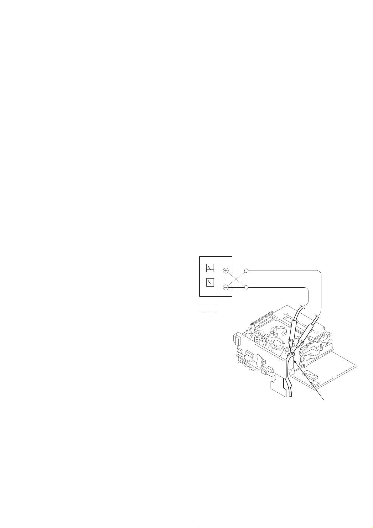
2. HOW TO TAKE A CASSETTE OUT
WHEN THE MAIN POWER CANNOT
BE TURNED ON
Note: To take a cassette out forcibly as follows when the main power
cannot be turned on, remove the cabinet (L) assembly . Apply +4.5
V power from an external power supply to the loading motor, as
shown below. Refer to sections 2-1 and 2-2 for the procedure to
remove the cabinet (L) assembly.
Procedure:
1) Disconnect the CN2504 of the MR-40 board.
2) Apply +4.5 V directly to the loading motor as shown to drive
the loading motor that ejects a cassette.
:unloading
:loading
Loading motor
— 5 —
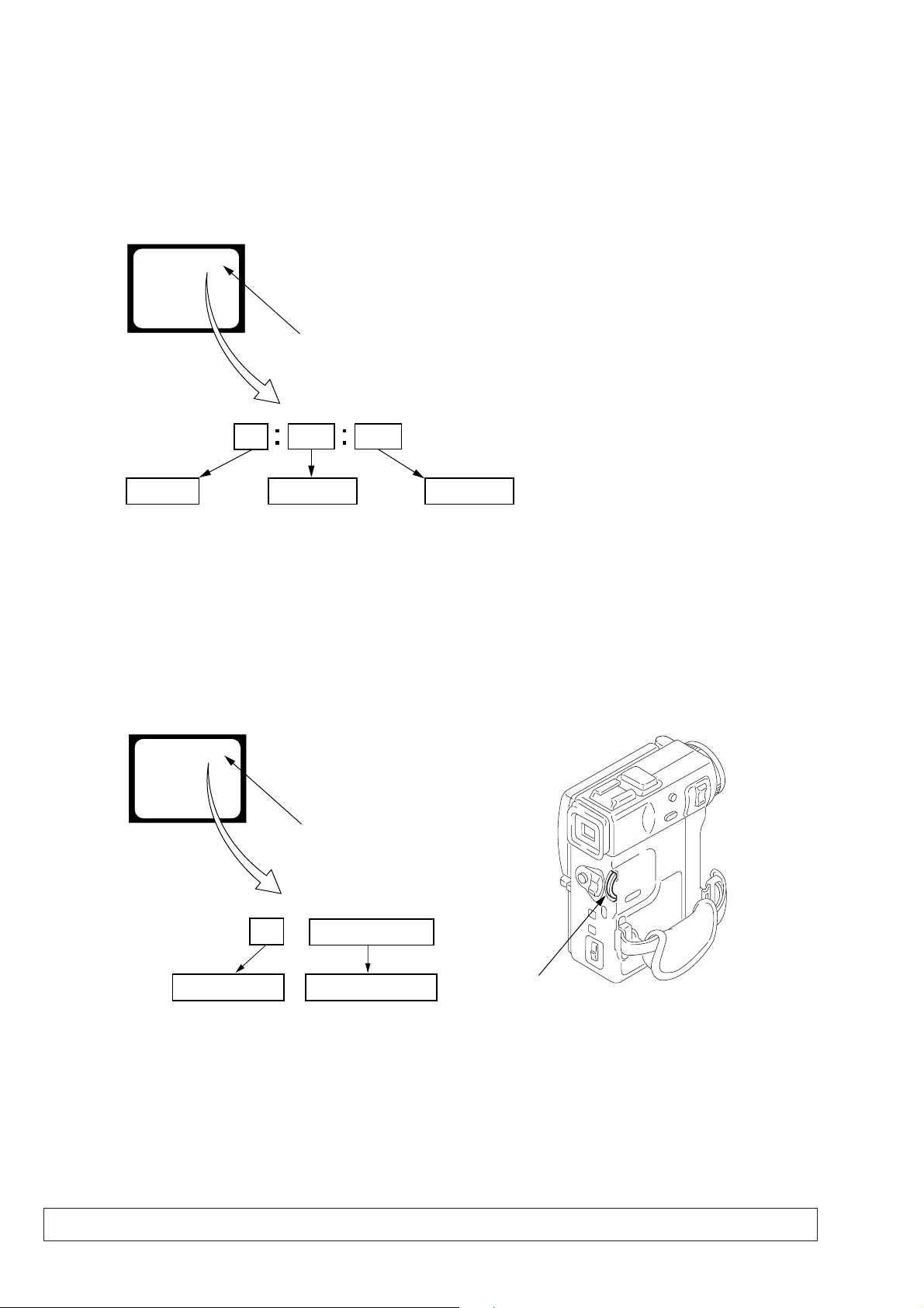
SELF-DIAGNOSIS FUNCTION
1. SELF-DIAGNOSIS FUNCTION
When problems occur while the unit is operating, the self-diagnosis
function starts working, and displays on the viewfinder or LCD
screen what to do. This function consists of two display; selfdiagnosis display and service mode display.
Details of the self-diagnosis functions are provided in the Instruction
manual.
Viewfinder or LCD screen
C : 3 1 : 1 1
Repaired by:
C : Corrected by customer
H : Corrected by dealer
E : Corrected by service
engineer
Blinks at 3.2Hz
3 1C
Block
Indicates the appropriate
step to be taken.
E.g.
31 ....Reload the tape.
32 ....Turn on power again.
1 1
2. SELF-DIAGNOSIS DISPLAY
When problems occur while the unit is operating, the counter of the
viewfinder shows a 4-digit display consisting of an alphabet and
numbers, which blinks at 3.2 Hz. This 5-character display indicates
the “repaired by:”, “block” in which the problem occurred, and
“detailed code” of the problem.
Detailed Code
Refer to page 7.
Self-diagnosis Code Table.
3. SER VICE MODE DISPLAY
The service mode display shows up to six self-diagnosis codes shown in the past.
3-1. Display Method
While pressing the “STOP” key, set the switch from OFF to “CAMERA” or “VTR or PLA YER”, and contin ue pressing the “ST OP” key for
10 seconds continuously. The service mode will be displayed, and the counter will show the backup No. and the 5-character self-diagnosis
codes.
3-2. Switching of Backup No.
By rotating the control dial, past self-diagnosis codes will be shown in order. The backup No. in the [] indicates the order in which the
problem occurred. (If the number of problems which occurred is less than 6, only the number of problems which occurred will be shown.)
[1] : Occurred first time [4] : Occurred fourth time
[2] : Occurred second time [5] : Occurred fifth time
[3] : Occurred third time [6] : Occurred the last time
Viewfinder or LCD screen
[3] C : 3 1 : 1 1
Backup No.
Order of previous errors
[3]
Lights up
C : 3 1 : 1 1
self-diagnosis codes
Control dial
3-3. End of Display
Turning OFF the power supply will end the service mode display.
Note: The self-diagnosis display data will be backed up by the coin-type lithium battery . When this coin-type lithium battery (CN2507 of MR-40 board)
is disconnected, the self-diagnosis data will be lost by initialization.
— 6 —
4. SELF-DIAGNOSIS CODE TABLE
Self-diagnosis Code
Repaired by:
C
C
C
C
C
C
C
C
C
C
C
C
C
C
C
C
C
C
C
C
C
C
C
E
E
E
E
Block
Function
21
22
23
31
31
31
31
31
31
31
31
31
31
31
31
32
32
32
32
32
32
32
32
61
61
62
62
Detailed
Code
00
00
00
10
11
20
21
22
23
24
30
40
42
10
11
20
21
22
23
24
30
40
42
00
10
00
01
Symptom/State
Condensation.
Video head is dirty.
Non-standard battery is used.
LOAD direction. Loading does not
complete within specified time
UNLOAD direction. Loading does not
complete within specified time
T reel side tape slacking when unloading
Winding S reel fault when counting the
rest of tape.
T reel fault.
S reel fault.
T reel fault.
FG fault when starting capstan.
FG fault when starting drum.
FG fault during normal drum operations.
LOAD direction loading motor time-
out.
UNLOAD direction loading motor
time-out.
T reel side tape slacking when
unloading.
Winding S reel fault when counting the
rest of tape.
T reel fault.
S reel fault.
T reel fault.
FG fault when starting capstan.
FG fault when starting drum
FG fault during normal drum
operations
Difficult to adjust focus
(Cannot initialize focus.)
Zoom operations fault
(Cannot initialize zoom lens.)
Steadyshot function does not work well.
(With pitch angular velocity sensor output
stopped.)
Steadyshot function does not work well.
(With yaw angular v elocity sensor output
stopped.)
Correction
Remove the cassette, and insert it again after one hour.
Clean with the optional cleaning cassette.
Use the info LITHIUM battery.
Load the tape again, and perform operations from the beginning.
Load the tape again, and perform operations from the beginning.
.
Load the tape again, and perform operations from the beginning.
Load the tape again, and perform operations from the beginning.
Load the tape again, and perform operations from the beginning.
Load the tape again, and perform operations from the beginning.
Load the tape again, and perform operations from the beginning.
Load the tape again, and perform operations from the beginning.
Load the tape again, and perform operations from the beginning.
Load the tape again, and perform operations from the beginning.
Remove the battery or power cable, connect, and perform
operations from the beginning.
Remove the battery or power cable, connect, and perform
operations from the beginning.
Remove the battery or power cable, connect, and perform
operations from the beginning.
Remove the battery or power cable, connect, and perform
operations from the beginning.
Remove the battery or power cable, connect, and perform
operations from the beginning.
Remove the battery or power cable, connect, and perform
operations from the beginning.
Remove the battery or power cable, connect, and perform
operations from the beginning.
Remove the battery or power cable, connect, and perform
operations from the beginning.
Remove the battery or power cable, connect, and perform
operations from the beginning.
Remove the battery or power cable, connect, and perform
operations from the beginning.
Inspect the lens block focus reset sensor (Pin 1 of CN450 of CD-
203 board) when focusing is performed when the focus ring is
rotated in the focus manual mode, and the focus motor drive circuit
(IC501 of VC-210 board) when the focusing is not performed.
Inspect the lens block zoom reset sensor (Pin !ª of CN450 of CD203 board) when zooming is performed when the zoom lens is
operated and the zoom motor drive circuit (IC501 of VC-210 board)
when zooming is not performed.
Inspect pitch angular velocity sensor (SE451 of CD-203 board)
peripheral circuits.
Inspect yaw angular velocity sensor (SE450 of CD-203 board)
peripheral circuits.
— 7 —
SECTION 1
GENERAL
DCR-PC1/PC1E
This section is extracted from instruction manual
of DCR-PC1E (3-864-275-51).
1-1
1-2
1-3
1-4
1-5
1-6
1-7
1-8

1-9
1-10
1-11
1-12
1-13
1-14
1-15
1-16
1-17
1-18
1-19
1-20
1-21
1-22
1-23
 Loading...