

Sony DCR-IP5E, DCR-IP7E Service Manual
DCR-IP5E/IP7E
RMT-817/818
SERVICE MANUAL
SERVICE MANUALSERVICE MANUAL
Level 1
Ver 1.0 2001. 10
Photo : DCR-IP7E
RMT-817
SPECIFICATIONS
Video camera
recorder
System
Video recording system
2 rotary heads
Helical scanning system
Audio recording system
Rotary heads, PCM system
Quantization: 12 bits
(Fs 48 kHz, stereo)
Video signal
PAL colour, CCIR standards
Usable cassette
MICROMV cassette with the
mark printed
Tape speed
Approx. 5.66 mm/s
Recording/playback time
(using cassette MGR60)
1 hour
Fastforward/rewind time
(using cassette MGR60)
Approx. 1 min and 30 s
Viewfinder
Electric viewfinder (colour)
Image device
3.0 mm (1/6 type) CCD
(Charge Coupled Device)
Approx. 800 000 pixels
(Effective: 400 000 pixels)
Lens
Carl Zeiss
Combined power zoom lens
Filter diameter 30 mm. (1 3/16 in.)
10× (Optical), 120× (Digital)
Focal length
2.3 - 23 mm (3/32 - 29/32 in.)
When converted to a 35 mm still
camera 44 - 440 mm (1 3/4 17 3/8 in.)
Colour temperature
Auto, HOLD (Hold),
(3 200 K),
Minimum illumination
7 lx (lux) (F 1.7)
Input/Output connectors
Audio/Video input/output
10-pin connector
Input/output auto switch
Video signal: 1 Vp-p, 75 Ω (ohms),
unbalanced, sync negative
Luminance signal: 1 Vp-p, 75 Ω
(ohms), unbalanced
Chrominance signal: 0.3 Vp-p, 75 Ω
(ohms), unbalanced
Audio signal: 327 mV, (at output
impedance more than 47 kΩ
(kilohms) )
Input impedance with more than
47 kΩ (kilohms)
Output impedance with less than
2.2 kΩ (kilohms)
USB jack
mini-B
i.LINK (MICROMV) input/output
4-pin connector S400
Outdoor (5 800 K)
Indoor
LCD screen
Picture
6.2 cm (2.5 type)
50 × 37 mm (2 × 1 1/2 in.)
Total dot number:
211 200 (960 × 220)
Wireless communication
(DCR-IP7E only)
Communication system
Bluetooth specification Ver. 1.1
Maximum communication
speed
Approx. 723 kbps
Maximum output
Bluetooth specification Power
Class2
Communication distance
Approx. 10 m (33 feet) (Open space,
when using a Sony BTA-NW1
Modem Adaptor with Bluetooth
Function)
Compatible Bluetooth profiles
Generic Access Profile
Dial-up Networking Profile
Usable frequency band
2.4 GHz band
(2.400 – 2.4835 GHz)
1)The maximum rate defined by
2)Depends on obstacles between
3)Defined by Bluetooth
1) 2)
2)
3)
Bluetooth specification Ver. 1.1
the Bluetooth devices, radio wave
conditions, etc.
specification for intended use
between the Bluetooth devices
AEP Model
UK Model
V MECHANISM
General
Power requirements
7.2 V (battery pack)
8.4 V (AC power adaptor)
Average power consumption
(when using the battery pack)
During camera recording using the
viewfinder (brightness normal)
3.5 W
During camera recording using the
LCD (Backlighting on) 4.2 W
During camera recording using the
LCD (Backlighting off) 3.5 W
Operating temperature
0°C to 40°C (32°F to 104°F)
Storage temperature
–20°C to +60°C (–4°F to +140°F)
Dimensions (approx.)
47× 103 × 80 mm
(1 7/8 × 4 × 3 1/8 in.) (w/h/d)
(excluding protruding parts)
Mass (approx.)
310 g (10 oz)
Main unit only
370 g (13 oz)
including the battery pack,
NP-FF50, cassette MGR60, lens cap,
and list strap
Supplied accessories
See page 3.
— Continued on next page —
DIGITAL VIDEO CAMERA RECORDER

DCR-IP5E/IP7E
AC power adaptor
AC-L20A
Power requirements
100 - 240 V AC, 50/60 Hz
Power consumption
23 W
Output voltage
DC OUT: 8.4 V, 1.5 A in the
operating mode
Operating temperature
0°C to 40°C (32°F to 104°F)
Storage temperature
–20°C to +60°C (–4°F to +140°F)
Dimensions (approx.)
125 × 39 × 62 mm
(5 × 1 9/16 ×2 1/2 in.) (w/h/d)
excluding (projecting parts) mains
lead
Mass (approx.)
280 g (9.8 oz)
excluding the mains lead
Table for difference of functions
Model
Remote commander
Memory mode
Memory stick
USB connector
NETWORK (Bluetooth)
(BT-003 board)
Maximum output voltage
DC 8.4 V
Output voltage
DC 7.2 V
Capacity
4.8 Wh (675 mAh)
Operating temperature
0°C to 40°C (32°F to 104°F)
Dimensions (approx.)
40.8 × 12.5 × 49.1 mm
(1 5/8 × 1/2 × 1 15/16 in.)
(w/h/d)
Mass (approx.)
45 g (1.6 oz)
Type
Lithium ion
DCR-IP5E
RMT-818
Battery pack
NP-FF50
DCR-IP7E
RMT-817
✕
✕
✕
✕
a
a
a
a
“Memory Stick”
(DCR-IP7E only)
Memory
Flash memory
8 MB: MSA-8A
Operating voltage
2.7-3.6 V
Power consumption
Approx. 45 mA in the operating
mode
Approx. 130 µA in the standby
mode
Dimensions (approx.)
50 × 2.8 × 21.5 mm
(2 × 1/8 × 7/8 in.) (w/h/d)
Mass (approx.)
4 g (0.14 oz)
Design and specifications are
subject to change without notice.
Remark
a: with IC1601, 1602, 1605,
1606, 1801, 1802, 1803
of VC-263 board
a: with BT-003 board
SAFETY-RELATED COMPONENT WARNING!!
COMPONENTS IDENTIFIED BY MARK 0 OR DOTTED LINE WITH
MARK 0 ON THE SCHEMATIC DIAGRAMS AND IN THE PARTS
LIST ARE CRITICAL TO SAFE OPERATION. REPLACE THESE
COMPONENTS WITH SONY PARTS WHOSE PART NUMBERS
APPEAR AS SHOWN IN THIS MANUAL OR IN SUPPLEMENTS
PUBLISHED BY SONY.
SAFETY CHECK-OUT
After correcting the original service problem, perform the following
safety checks before releasing the set to the customer.
1. Check the area of your repair for unsoldered or poorly-soldered
connections. Check the entire board surface for solder splashes
and bridges.
2. Check the interboard wiring to ensure that no wires are
"pinched" or contact high-wattage resistors.
3. Look for unauthorized replacement parts, particularly
transistors, that were installed during a previous repair . Point
them out to the customer and recommend their replacement.
4. Look for parts which, through functioning, show obvious signs
of deterioration. Point them out to the customer and
recommend their replacement.
5. Check the B+ voltage to see it is at the values specified.
6. Flexible Circuit Board Repairing
• Keep the temperature of the soldering iron around 270˚C
during repairing.
• Do not touch the soldering iron on the same conductor of the
circuit board (within 3 times).
• Be careful not to apply force on the conductor when soldering
or unsoldering.
— 2 —
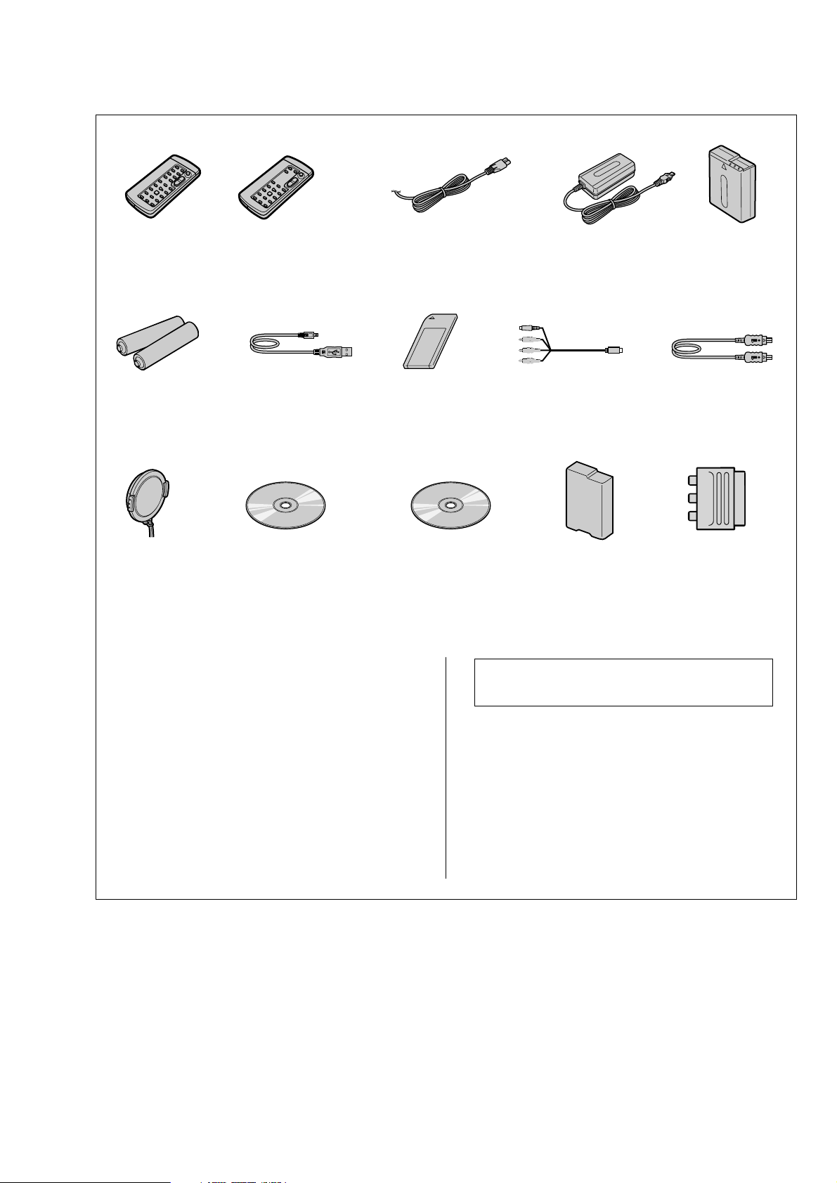
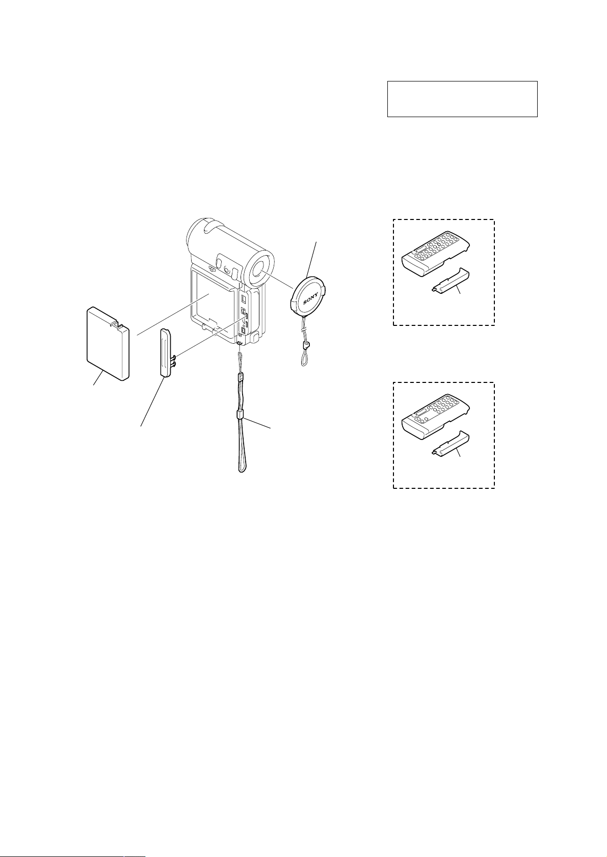
Checking supplied accessories.
Make sure that the following accessories are supplied with your camcorder.
DCR-IP5E/IP7E
Wireless Remote
Commander (1)
RMT-817: DCR-IP7E
1-476-815-21
R6 (size AA) batteries for
Remote Commander (2)
(not supplied)
Lens cap (1)
X-3951-910-1
Wireless Remote
Commander (1)
RMT-818: DCR-IP5E
1-476-814-21
USB Cable (1)
(75 cm)
1-757-293-11
(DCR-IP7E only)
CD-ROM
(SPVD-004(P) USB Driver)(1)
3-066-676-01
(DCR-IP7E only)
Power cord (Main lead)(1) (AEP model)
0
Power cord (Main lead)(1) (UK model)
0
1-769-608-11
1-783-374-11
Memory stick (1)
(MSA-8A)
A-7024-735-A
(DCR-IP7E only)
CD-ROM
(Movie Shaker Ver.3.1
for MICROMV)(1)
3-070-810-01
AC Power Adaptor (1)
(AC-L20A)
0
1-476-779-11
A/V Connecting Cable (1)
(1.5 m)
1-823-156-11
Battery Cover (1)
3-070-945-01
Battrey Pack (1)
(NP-FF50)
(not supplied)
i.LINK Cable (1)
(not supplied)
21-pin adaptor (1)
1-573-291-11
Other accessories
3-071-132-11 OPERATING INSTRUCTION (NETWORK)
(ENGLISH/FRENCH) (IP7E)
3-071-132-21 OPERATING INSTRUCTION (NETWORK)
(GERMAN/DUTCH) (IP7E:AEP)
3-071-132-51 OPERATING INSTRUCTION (NETWORK) (ITALIAN)
3-071-133-11 OPERATING INSTRUCTION (SET)(ENGLISH/RUSSIAN)
3-071-133-21 OPERATING INSTRUCTION (SET)(FRENCH/GERMAN)
(IP5E:AEP/IP7E:AEP)
3-071-133-31 OPERATING INSTRUCTION (SET)(DUTCH)
(IP5E:AEP/IP7E:AEP)
3-071-133-41 OPERATING INSTRUCTION (SET)
(SPANISH/PORTUGUESE) (IP5E:AEP/IP7E:AEP)
3-071-133-51 OPERATING INSTRUCTION (SET)(ITALIAN/GREEK)
(IP5E:AEP/IP7E:AEP)
Note : The components identified by mark 0 or dotted
line with mark 0 are critical for safety.
Replace only with part number specified.
(IP7E:AEP)
— 3 —

DCR-IP5E/IP7E
TABLE OF CONTENTS
SERVICE NOTE
1. POWER SUPPLY DURING REPAIRS ·····························5
2. TO TAKE OUT A CASSETTE WHEN NOT EJECT
(FORCE EJECT) ································································ 5
SELF-DIAGNOSIS FUNCTION
1. SELF-DIAGNOSIS FUNCTION······································· 6
2. SELF-DIAGNOSIS DISPLAY ·········································· 6
3. SERVICE MODE DISPLAY ·············································6
3-1. Display Method ·································································· 6
3-2. Backup No.········································································· 6
3-3. End of Display···································································· 6
4. SELF-DIAGNOSIS CODE TABLE··································· 7
1. MAIN PARTS
1. ORNAMENTAL PARTS···················································· 8
2. DISASSEMBLY································································· 9
2-1. LCD SECTION (PD-142 BOARD) ································· 10
2-2. CABINET (R) SECTION ················································ 11
2-3. LENS SECTION (LD-105 BOARD)······························· 12
2-4. VC-263 BOARD ······························································ 13
2-5. MECHANISM DECK······················································ 13
2-6. EVF SECTION (VF-149 BOARD)··································14
2-7. CONTROL SWITCH BLOCK (CF-1900), SPEAKER··· 14
2-8. JK-209 BOARD ······························································· 15
2-9. PARTS UNIT (HINGE) ··················································· 16
2-10. BT-003 BOARD (IP7E), CABINET (L) ASSEMBLY ····17
2-11. GRIP CABINET ASSEMBLY,
CONTROL SWITCH BLOCK (FK-1900) ······················ 17
3. REPAIR PARTS LIST ······················································ 18
3-1. EXPLODED VIEWS ······················································· 18
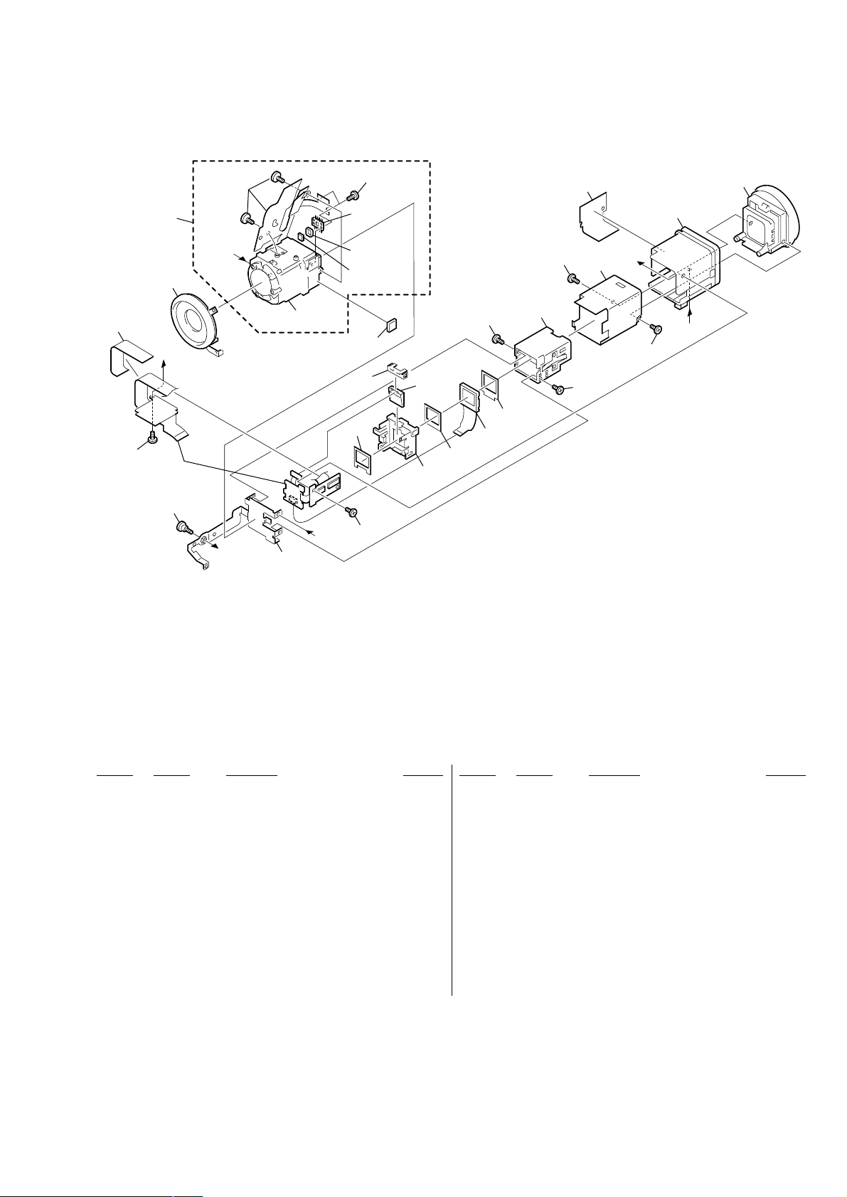
3-1-1.OVERALL SECTION······················································ 18
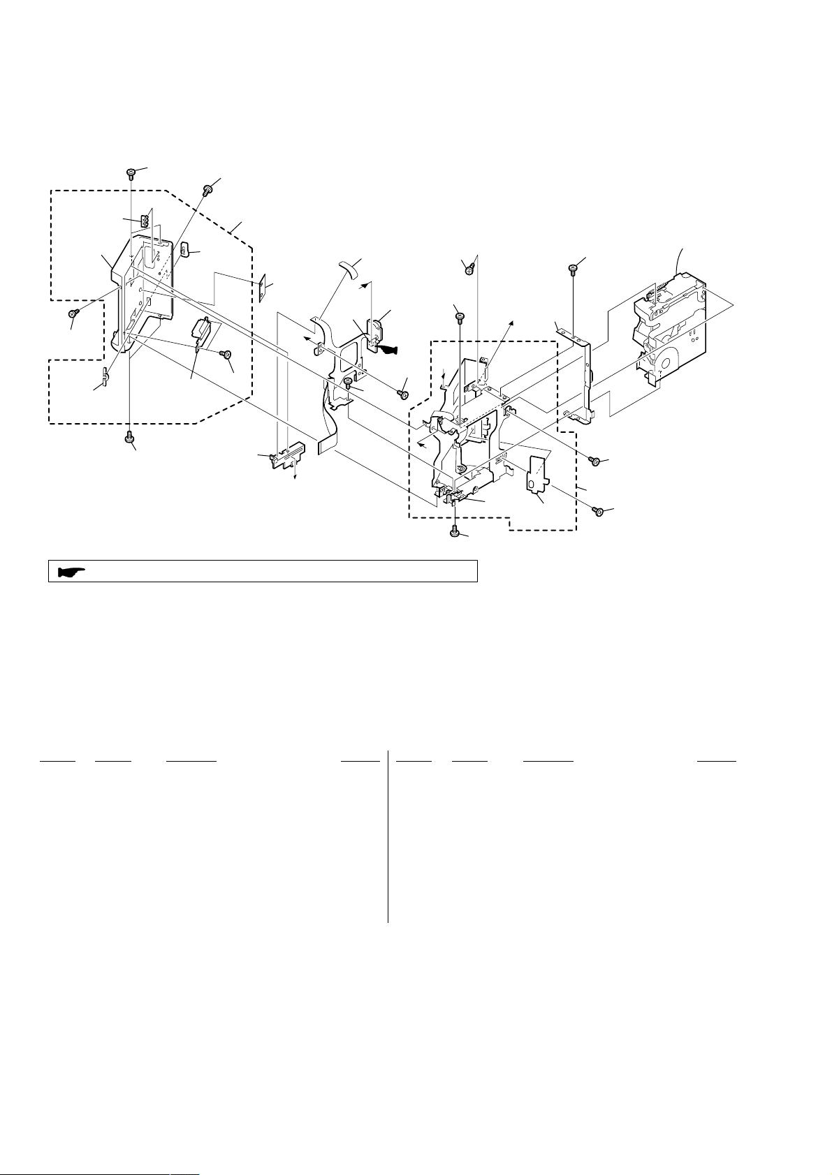
3-1-2.CABINET (R) SECTION-1 ············································· 19
3-1-3.CABINET (R) SECTION-2 (LCD SECTION)················ 20
3-1-4.LENS-EVF SECTION ····················································· 21
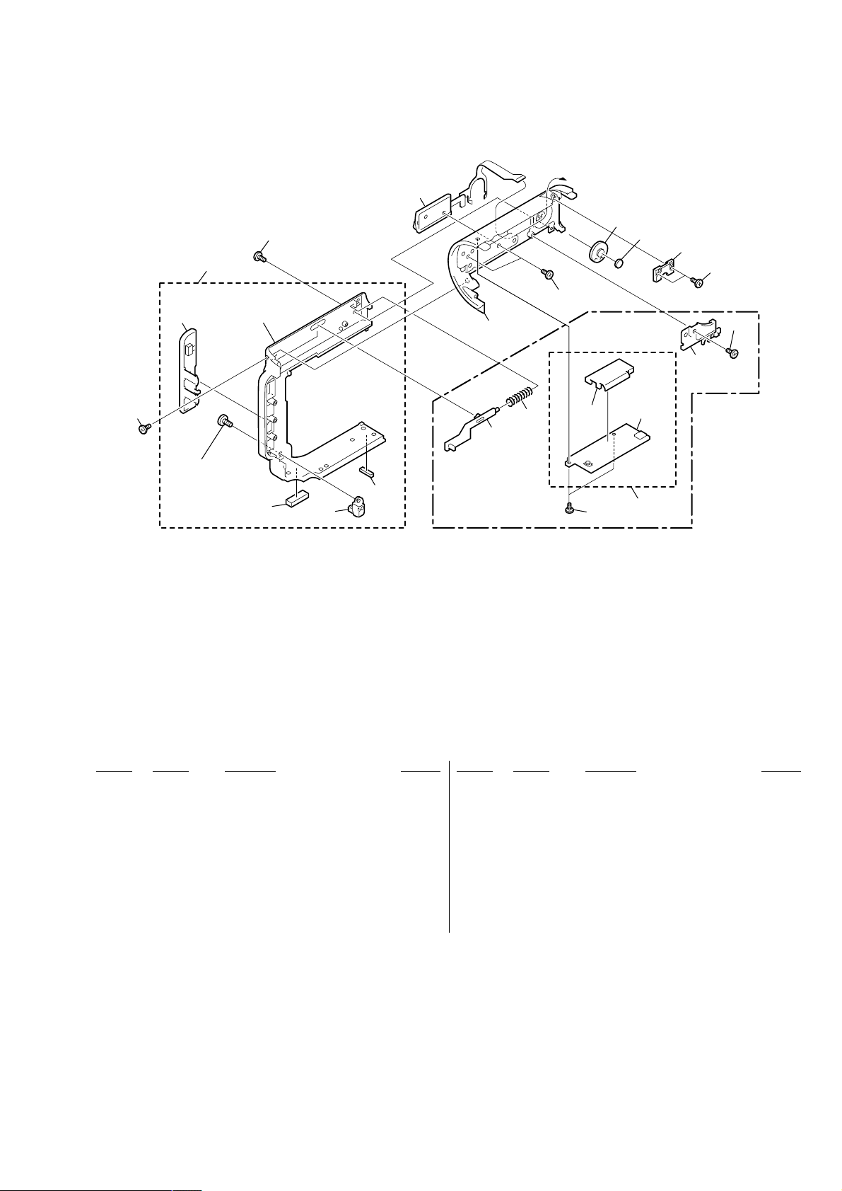
3-1-5.G CABINET SECTION··················································· 22
3-1-6.CABINET (L) SECTION················································· 23
2. GENERAL
Main Features ············································································· 24
Introduction – Basic operations·················································· 24
Quick Start Guide ······································································· 25
Getting started
Using this manual ···································································26
Checking supplied accessories ··············································· 26
Step 1 Preparing the power supply ········································· 27
Installing the battery pack···················································· 27
Charging the battery pack ···················································· 27
Connecting to the mains ······················································28
Step 2 Setting the date and time ············································· 29
Step 3 Inserting a cassette······················································· 30
Recording – Basics
Recording a picture································································· 30
Shooting backlit subjects – BACK LIGHT ························· 32
Self-timer recording····························································· 33
Checking the recording – END SEARCH······························ 33
Playback – Basics
Playing back a tape ································································· 33
Viewing the recording on the TV screen ································ 35
Advanced Recording Operations
Recording a still image on a tape – Tape Photo recording ····· 36
Using the wide mode ······························································37
Using the fader function ························································· 37
Using special effects – Picture effect······································ 38
Using special effects – Digital effect······································ 38
Using the PROGRAM AE function ········································ 39
Adjusting the white balance manually···································· 40
Adjusting the exposure manually ···········································41
Focusing manually·································································· 41
Advanced Playback Operations
Playing back a tape with picture effects ·································42
Playing back a tape with digital effects ·································· 42
Searching for a scene – Multi-picture search ························· 43
Searching the boundaries of recorded tape by title
– Title search········································································ 44
Searching a recording by date – Date search·························· 44
Searching for a photo – Photo search ·····································45
Editing
Dubbing a tape ········································································ 45
Recording a programme ························································· 46
Superimposing a title ······························································ 48
Making your own titles ··························································· 50
The Micro Cassette Memory ··················································51
Customizing Y our Camcorder
Changing the menu settings···················································· 52
“Memory Stick” Operations – DCR-IP7E only
Using a “Memory Stick” – introduction ································· 53
Recording still images on a “Memory Stick”
– Memory Photo recording ·················································· 57
Recording an image from a tape as a still image ···················· 58
Recording moving pictures on a “Memory Stick”
– MPEG movie recording ···················································· 59
Recording a picture from a tape as a moving picture ············· 60
Superimposing a still image in a “Memory Stick” on a
moving picture – MEMORY MIX ······································ 61
Copying still images from a tape – Photo save······················· 62
Viewing a still image – Memory photo playback ··················· 63
Viewing a moving picture – MPEG movie playback ············· 64
Dubbing images recorded on the “Memory Stick” onto
the tape················································································· 65
Enlarging still images recorded on a “Memory Stick”
– Memory PB ZOOM ·························································· 66
Playing back images in a continuous loop – SLIDE SHOW ····
Preventing accidental erasure – Image protection ·················· 67
Deleting images ······································································ 67
Writing a print mark – PRINT MARK··································· 69
Connecting with a computer
Viewing images recorded on a tape using your computer ······69
Viewing images recorded on a “Memory Stick” using
your computer – DCR-IP7E only ········································70
Network operation – DCR-IP7E only
Accessing the network ···························································· 72
Troubleshooting
Types of trouble and their solutions ········································ 72
Self-diagnosis display ····························································· 74
Warning indicators and messages ···········································74
Additional Information
Compatible cassettes······························································· 74
About the “InfoLITHIUM” battery pack································ 75
About i.LINK·········································································· 75
Using your camcorder abroad················································· 76
Maintenance information and precautions······························ 76
Quick Reference
Identifying the parts and controls ··········································· 78
66
— 4 —
SERVICE NOTE
DCR-IP5E/IP7E
1. POWER SUPPLY DURING REPAIRS
In this unit, about 10 seconds after power is supplied to the battery terminal using the regulated power supply (8.4V), the po wer is shut of f so
that the unit cannot operate.
These following two methods are available to prevent this. Take note of which to use during repairs.
Method 1.
Use the AC power adaptor (AC-L20, AC-VF50).
Method 2.
Connect the servicing remote commander RM-95 (J-6082-053-B) to the A/V jack, and set the commander switch to the “ADJ” side.
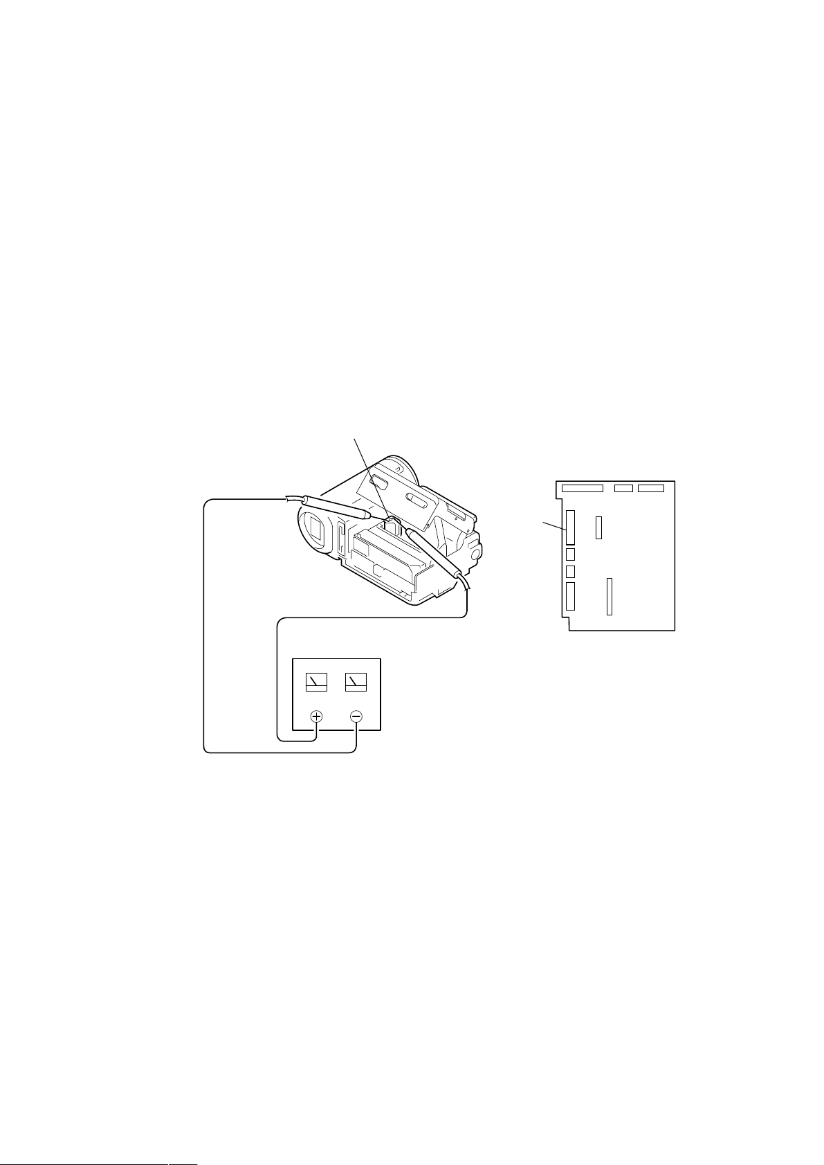
2. TO TAKE OUT A CASSETTE WHEN NOT EJECT (FORCE EJECT)
1 Refer to 2-2 to remove the cabinet (R) assembly.
2 Disconnect CN2009 (31P, 0.3mm) of VC-263 board.
3 Open the cassette lid.
4 Supply +4.5V from the regulated power supply to the loading motor and unload with a pressing the cassette compartment.
Loading motor
Regulated power supply
(+4.5Vdc)
CN2009
VC-263 board
— 5 —
DCR-IP5E/IP7E
SELF-DIAGNOSIS FUNCTION
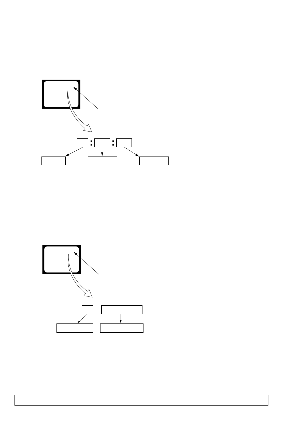
1. SELF-DIAGNOSIS FUNCTION
When problems occur while the unit is operating, the self-diagnosis
function starts working, and displays on the viewfinder or LCD
screen what to do. This function consists of two display; selfdiagnosis display and service mode display.
Details of the self-diagnosis functions are provided in the Instruction
manual.
Viewfinder or LCD screen
C : 3 1 : 1 1
Repaired by:
C : Corrected by customer
H : Corrected by dealer
E : Corrected by service
engineer
Blinks at 3.2Hz
3 1C
Block
Indicates the appropriate
step to be taken.
E.g.
31 ....Reload the tape.
32 ....Turn o n power again.
1 1
2. SELF-DIAGNOSIS DISPLAY
When problems occur while the unit is operating, the counter of the
viewfinder or LCD screen consists of an alphabet and 4-digit
numbers, which blinks at 3.2 Hz. This 5-character display indicates
the “repaired by:”, “block” in which the problem occurred, and
“detailed code” of the problem.
Detailed Code
Refer to page 7.
Self-diagnosis Code Table.
3. SER VICE MODE DISPLAY
The service mode display shows the last self-diagnosis codes shown in the past.
3-1. Display Method
While pressing the “BACK LIGHT” key, set the switch from OFF to ON, and continue pressing the “BACK LIGHT” key for 5 seconds
continuously. The service mode will be displayed, and the counter will show the backup No. and the 5-character self-diagnosis codes.
3-2. Backup No.
Viewfinder or LCD screen
[3] C : 3 1 : 1 1
Lights up
[3]
Backup No.
Order of previous errors
The backup No. in the [] indicates the order in which the problem occurred. (If the number of problems which occurred is less than 6, only the
number of problems which occurred will be shown.)
[1] : Occurred first time [4] : Occurred fourth time
[2] : Occurred second time [5] : Occurred fifth time
[3] : Occurred third time [6] : Occurred the last time
Note: Switching of the backup No. can’t be done.
C : 3 1 : 1 1
Self-diagnosis Codes
3-3. End of Display
Turning OFF the power supply will end the service mode display.
Note: The “self-diagnosis display” data will be backed up by the coin-type lithium battery of control switch block (FK-1900) BT001. When CN2024 of
VC-263 board is disconnected, the “self-diagnosis display” data will be lost by initialization.
— 6 —

4. SELF-DIAGNOSIS CODE TABLE
Self-diagnosis Code
DCR-IP5E/IP7E
Function
Repaired by:
C
C
C
C
C
C
C
C
C
C
C
C
C
C
C
C
C
C
C
C
C
C
C
C
C
C
C
E
E
Block
04
21
22
31
31
31
31
31
31
31
31
31
31
31
31
32
32
32
32
32
32
32
32
32
32
32
32
61
61
Detailed
Code
00
00
00
10
11
20
21
22
23
31
32
40
41
42
43
10
11
20
21
22
23
31
32
40
41
42
43
00
10
Symptom/State
Non-standard battery is used.
Condensation.
Video head is dirty.
LOAD direction. Loading does not
complete within specified time
UNLOAD direction. Loading does not
complete within specified time
T reel side tape slacking when unloading
Winding S reel fault when unloading.
T reel fault.
S reel fault.
FG fault during capstan operations.
Capstan reverse rotation.
FG fault when starting drum.
PG fault
FG fault during normal drum operations.
PG fault during normal drum operations.
LOAD direction loading motor time-
out.
UNLOAD direction loading motor
time-out.
T reel side tape slacking when
unloading.
Winding S reel fault when unloading.
T reel fault.
S reel fault.
FG fault during capstan operations
Captan reverse operations
FG fault when starting drum
PG fault when starting drum
FG fault during normal drum
operations
PG fault during normal drum
operations
Difficult to adjust focus
(Cannot initialize focus.)
Zoom operations fault
(Cannot initialize zoom lens.)
when starting drum.
Correction
Use the info LITHIUM battery.
Remove the cassette, and insert it again after one hour.
Clean with the optional cleaning cassette.
Load the tape again, and perform operations from the beginning.
Load the tape again, and perform operations from the beginning.
.
Load the tape again, and perform operations from the beginning.
Load the tape again, and perform operations from the beginning.
Load the tape again, and perform operations from the beginning.
Load the tape again, and perform operations from the beginning.
Load the tape again, and perform operations from the beginning.
Load the tape again, and perform operations from the beginning.
Load the tape again, and perform operations from the beginning.
Load the tape again, and perform operations from the beginning.
Load the tape again, and perform operations from the beginning.
Load the tape again, and perform operations from the beginning.
Remove the battery or power cable, connect, and perform
operations from the beginning.
Remove the battery or power cable, connect, and perform
operations from the beginning.
Remove the battery or power cable, connect, and perform
operations from the beginning.
Remove the battery or power cable, connect, and perform
operations from the beginning.
Remove the battery or power cable, connect, and perform
operations from the beginning.
Remove the battery or power cable, connect, and perform
operations from the beginning.
Remove the battery or power cable, connect, and perform
operations from the beginning.
Remove the battery or power cable, connect, and perform
operations from the beginning.
Remove the battery or power cable, connect, and perform
operations from the beginning.
Remove the battery or power cable, connect, and perform
operations from the beginning.
Remove the battery or power cable, connect, and perform
operations from the beginning.
Remove the battery or power cable, connect, and perform
operations from the beginning.
Inspect the lens block focus MR sensor (Pin rh,rj of CN2021 of VC-
263 board) when focusing is performed using the manual focus buttons
on the menu screen, and the focus motor drive signals (Pin ea,es of
CN2021 of VC-263 board) when the focusing is not performed.
Inspect the lens block zoom MR sensor (
VC-263 board
is operated and the zoom motor drive signals (
of VC-263 board
) when zooming is performed when the zoom switch
) when zooming is not performed.
Pin rl,t; of CN2021 of
Pin wl,e; of CN2021
— 7 —
DCR-IP5E/IP7E
1. MAIN PARTS
Note:
• Follow the disassembly procedure in the numerical order given.
• Items marked “*” are not stocked since they are seldom required for routine service.
Some delay should be anticipated when ordering these items.
• The parts numbers of such as a cabinet are also appeared in this section.
Refer to the parts number mentioned below the name of parts to order.
1. ORNAMENTAL PARTS
Lens cap assembly
X-3951-910-1
The components identified by mark 0 or
dotted line with mark 0 are critical for safety.
Replace only with part number specified.
Remote commander (RMT-817)
1-476-815-21
(IP7E)
Lid battery case
(for RMT-817)
3-053-056-01
BT terminal cover
3-070-945-01
Jack cover
3-069-883-01
Note: Disassembling the main unit
is necessary to replace it.
Remote commander (RMT-818)
1-476-814-21 (IP5E)
List strap
3-069-932-01
Lid battery case
(for RMT-818)
3-053-056-01
— 8 —

2. DISASSEMBLY
The following flow chart shows the disassembly procedure.
2-1. LCD section (PD-142 board)
2-2. Cabinet (R) section
2-3. Lens section (LD-105 board)
DCR-IP5E/IP7E
2-6. EVF section (VF-149 board)
2-7. Control switch block (CF-1900), Speaker2-4. VC-263 board
DCR-IP5E/IP7E
2-5. Mechanism deck
2-8. JK-209 board
2-9. Parts unit (Hinge)
2-10. BT-003 board (IP7E), Cabinet (L) assembly
2-11. Grip cabinet assembly,
Control switch block (FK-1900)
— 9 —
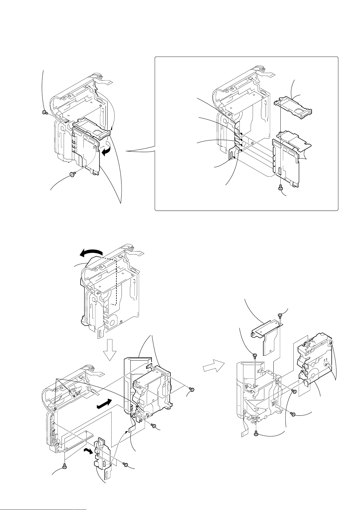
DCR-IP5E/IP7E
NOTE: F ollo w the disassembly procedure in the numerical order given.
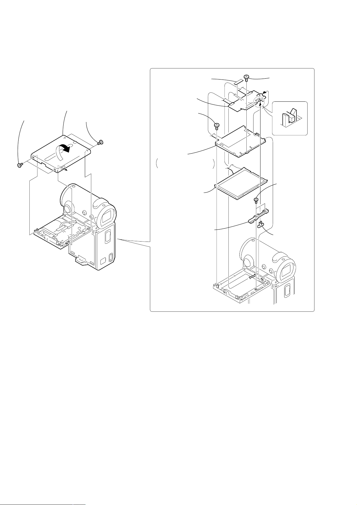
2-1. LCD SECTION (PD-142 BOARD)
REMOVING THE PD-142 BOARD
3 Remove the panel cabinet (R) assembly
in the direction of the arrow.
1 T wo screws
(M1.4 × 2.5),
lock ace
PD-142
2 T wo screws
(M1.4 × 2.5),
lock ace
4 T ape (F)
8 PD-142
board
5 Screw
(M1.4 × 2.5),
lock ace
9 Back light
Cold cathode fluorescent
tube, BL shield sheet (N)
6 Liquid crystal
indicator module
qa LED SW base
7 Screw
(M1.4 × 2.5),
lock ace
PD-142
0 T wo screws
(M1.4 × 2.5),
lock ace
qs LED SW knob
— 10 —
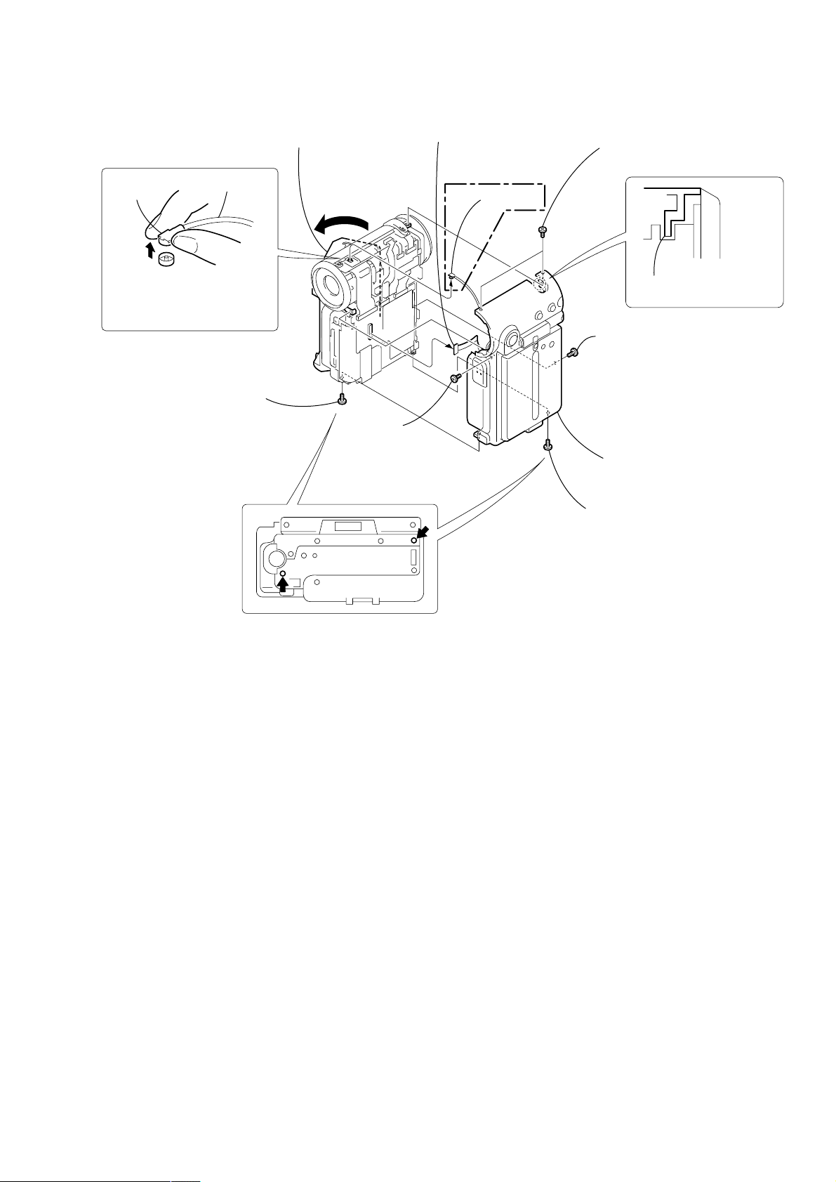
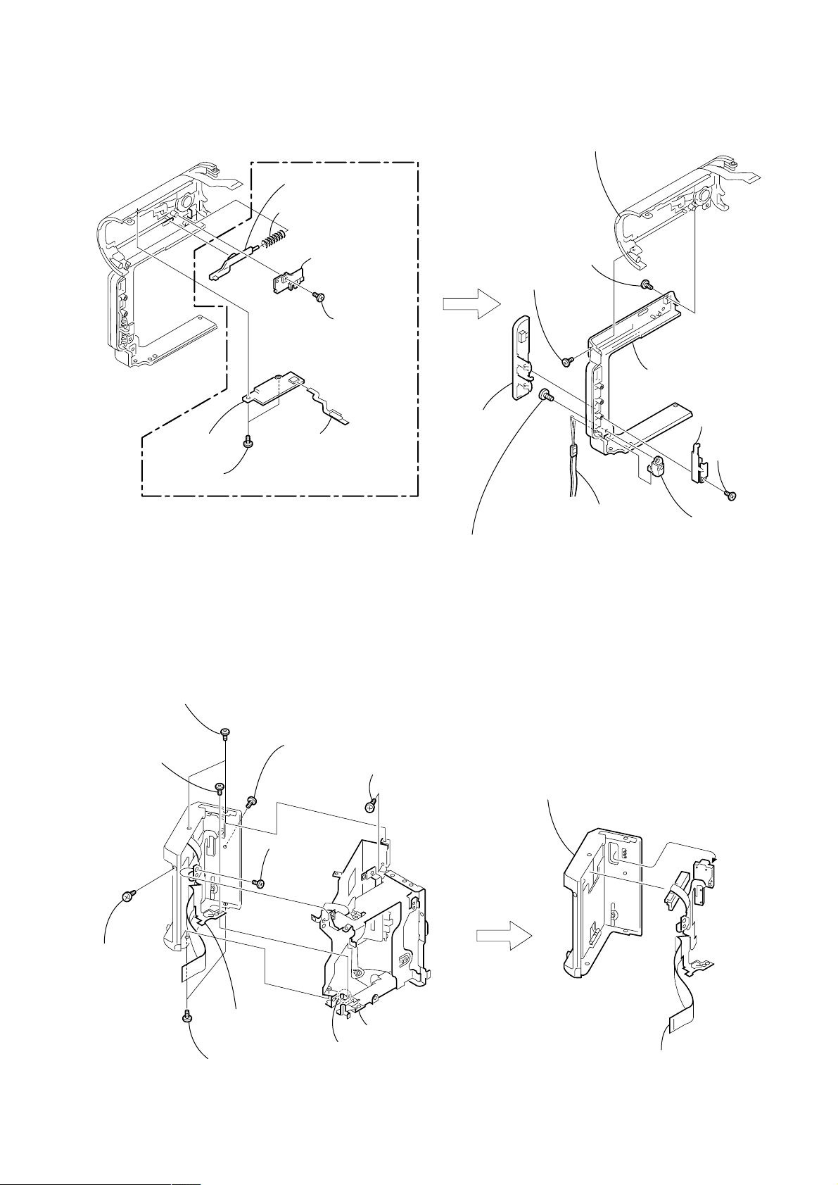
2-2. CABINET (R) SECTION
DCR-IP5E/IP7E
(IP7E)
BT cable
connector
When removing the BT cable
from the BT-003 board, be sure
to hold the connector of the
BT cable and remove it.
BT cable
3 Screw
(M1.4 × 2.5),
lock ace
5 Open the grip
cabinet assembly.
VC-263
2 Screw
(M1.4 × 2.5),
lock ace
8 FP-366 flexible board
(40P)
(IP7E)
7 Antenna
1 Two screws (M1.4 × 2.5),
lock ace
When installing cabinet (L)
section insert it in the groove.
6 Screw (M1.4 × 2.5),
lock ace
9 Cabinet (R) section
4 Screw (M1.4 × 2.5),
lock ace
— 11 —
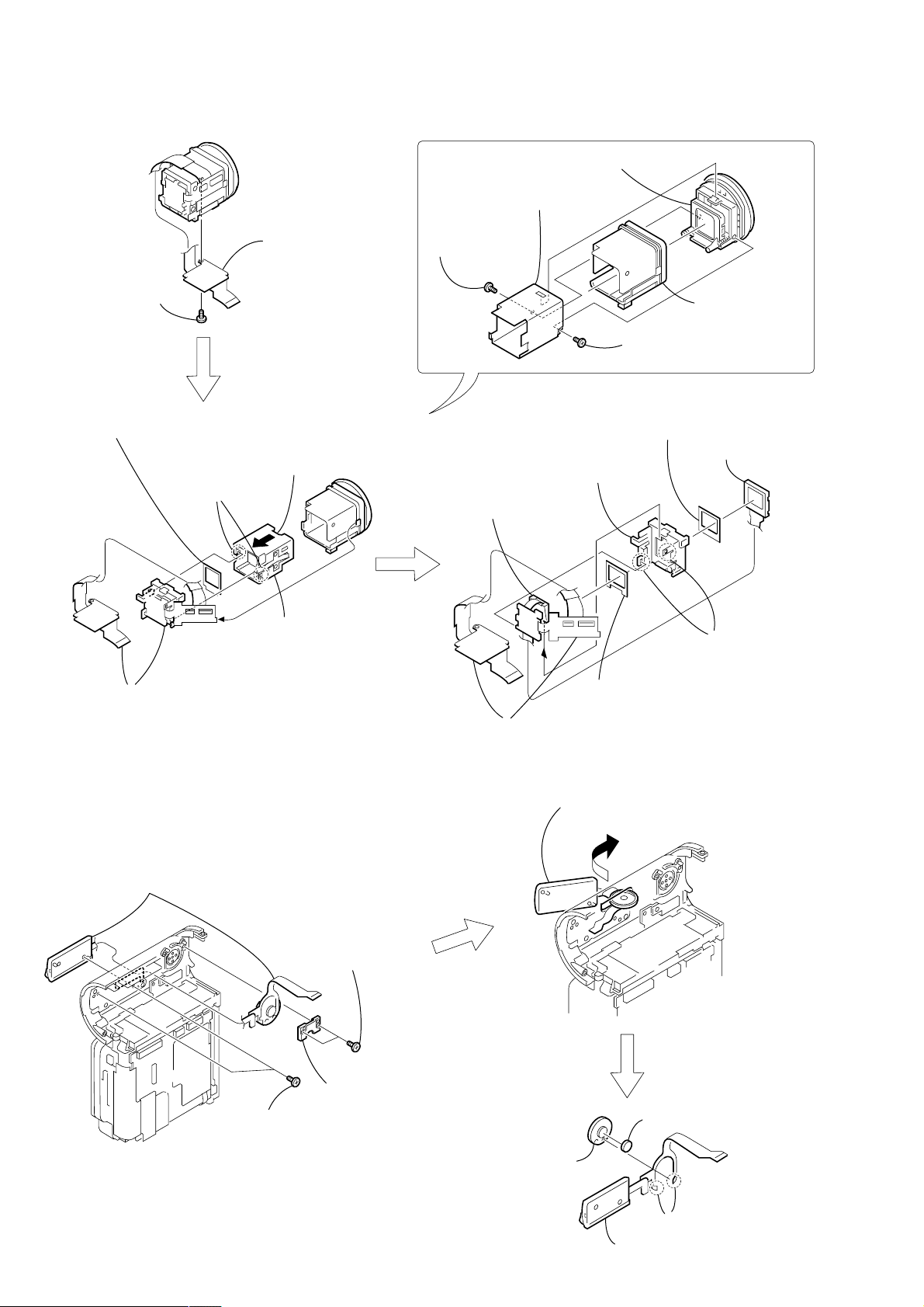
DCR-IP5E/IP7E
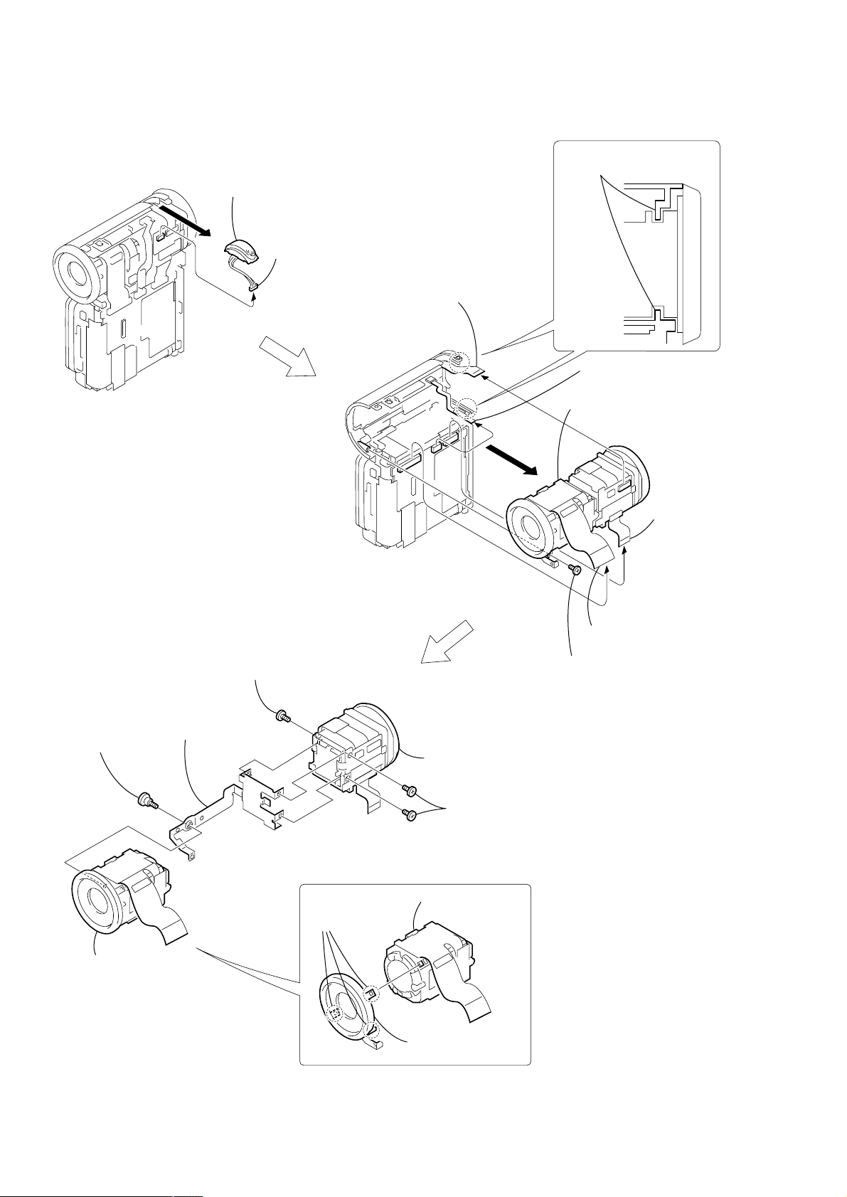
2-3. LENS SECTION (LD-105 BOARD)
2 Remove the microphone unit
in the direction of the arrow A.
A
VC-263
When installing cabinet (L)
section insert it in the groove.
1 Microphone unit
(4P)
1 Control switch block
(CF-1900) (14P)
2 FP-367 flexible board (15P)
(IP7E)
6 Remove the lens-EVF section
in the direction of the arrow B.
1 T apping screw
(M1.7 × 3.5)
4 Screw (M1.4 × 2.5),
lock ace
5 VF fixed plate
assembly
B
VC-263
LD-105
9
4
-1
F
V
3
EVF section,
VF-149 board
(33P)
4
LD-105 board
(51P)
5 Screw (M1.4 × 2.5),
lock ace
9
4
-1
F
V
6 EVF section
3 Two screws (M1.4 × 2.5),
lock ace
LD-105
2 Lens section
3 Lens section
1 Three claws
LD-105
2 Filter ring assembly
— 12 —
2-4. VC-263 BOARD
1 Screw (M1.4 × 2.5),
lock ace
REMOVING THE VC-263 BO ARD
2 Flexible board
(from sensor) (31P)
3 Flexible board
(from video head)
(11P)
DCR-IP5E/IP7E
7
MS holder
assembly (IP7E)
VC PC board
7
holder (IP5E)
VC-263
2 Screw (M1.4 × 2.5),
lock ace
3 Open the VC-263 board,
MS holder assembly (IP7E)/
VC PC board holder (IP5E)
in the direction of the arrow.
2-5. MECHANISM DECK
1 Open the grip
cabinet
assembly
4 Flexible board
(from drum motor) (11P)
1 JK-209 board
CN5504 (60P)
6 Remove the grip
cabinet assembly
in the direction of
the arrow A.
5 Flexible board
(from capstan motor) (19P)
0 VC heat
sink assembly
qa T wo screws
(M1.4 × 2.5),
lock ace
VC-263
6 T apping screw
(M1.7 × 3.5)
9 Screw
(M1.4 × 2.5),
lock ace
8 VC-263
board
Three
dowels
4 T wo screws
(M1.4 × 2.5),
lock ace
B
A
5 Control switch block
(FK-1900) (31P)
7 Two screws (M1.4 × 2.5),
lock ace
8 Remove the JK-209 board
in the direction of the arrow B.
2 T wo screws
(M1.4 × 2.5),
lock ace
3 Screw
(M1.4 × 2.5),
lock ace
— 13 —
Two
dowels
qf Mechanism
deck
qd Screw
(M1.4 × 2),
ace
qs T wo screws
(M1.4 × 2.5),
lock ace
DCR-IP5E/IP7E
)
)
2-6. EVF SECTION (VF-149 BOARD)
3 VF lens assembly
4 VF sleeve
VF-149 board
1 T apping screw
(M1.7 × 3.5)
5 LCD cushion (1)
(Shining side must face to the VF sleeve guide assembly.)
VF-149
4 VF-149 board block
VF-149
2 Push the VF sleeve guide assembly
in the direction of the arrow.
3 Two claws
6 VF sleeve guide
assembly
2 T apping screw
(M1.7 × 5)
0 Light guide plate block,
BL retainer sheet metal
VF-149
qa VF-149 board
5 VF ring assembly,
VF guard sheet
1 T apping screw
(M1.7 × 5)
8 LCD cushion (2)
(Shining side must face to the BL holder.
7 LCD
qd
BL holder
qs BL cushion
(Shining side must face to the BL holder.)
(LCX033AN-J
9 T wo claws
2-7. CONTROL SWITCH BLOCK (CF-1900), SPEAKER
4 Control switch block (CF-1900),
Speaker
1 T wo screws
(M1.4 × 2.5),
lock ace
VC-263
3 T wo screws
(M1.4 × 2.5),
lock ace
2 SP retainer
5 Remove the control switch block (CF-1900),
speaker in the direction of the arrow.
7 SP cushion
8 Speaker
6 Remove soldering
from the two points
9 Control switch block (CF-1900)
— 14 —
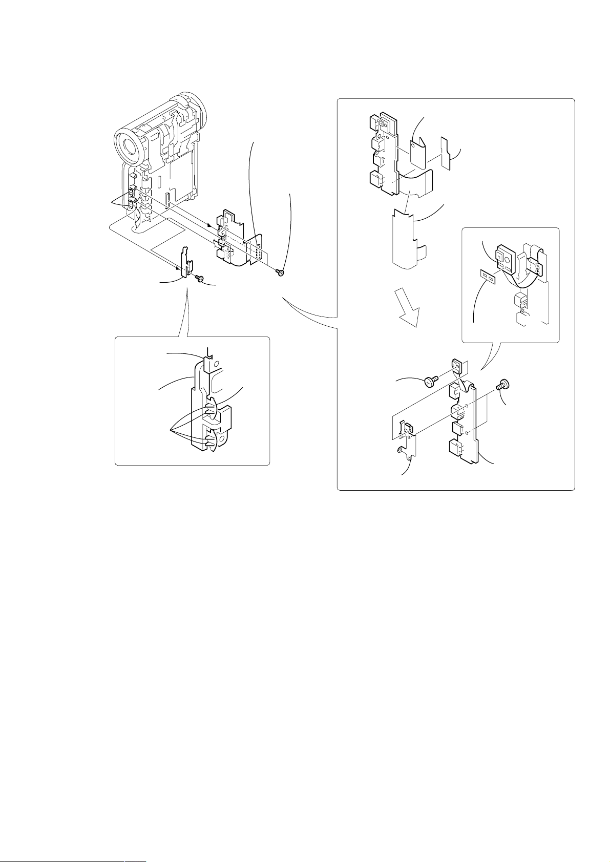
2-8. JK-209 BOARD
VC-263
2 Jack
cover
4 Connector
CN5504 (60P)
5 T wo screws
(M1.4 × 2.5),
lock ace
DCR-IP5E/IP7E
REMOVING THE JK-209 BOARD
3 JK flexible protection
sheet 2
2 JK flexible
protection sheet
JK-209
1 JK PC board
protection sheet
3 JC retainer
plate
JK bracket
assembly
JC retainer
plate
Four claws
JK-209
1 Screw
(M1.4 × 2.5),
lock ace
Jack
cover
JK-209 board
JK-209
5 T ally light
interception sheet
4 Screw
(M1.4 × 2),
lock ace
6 T wo screws
(M1.4 × 2),
ace
JK-209
8 JK-209 board
7 JK bracket assembly
— 15 —
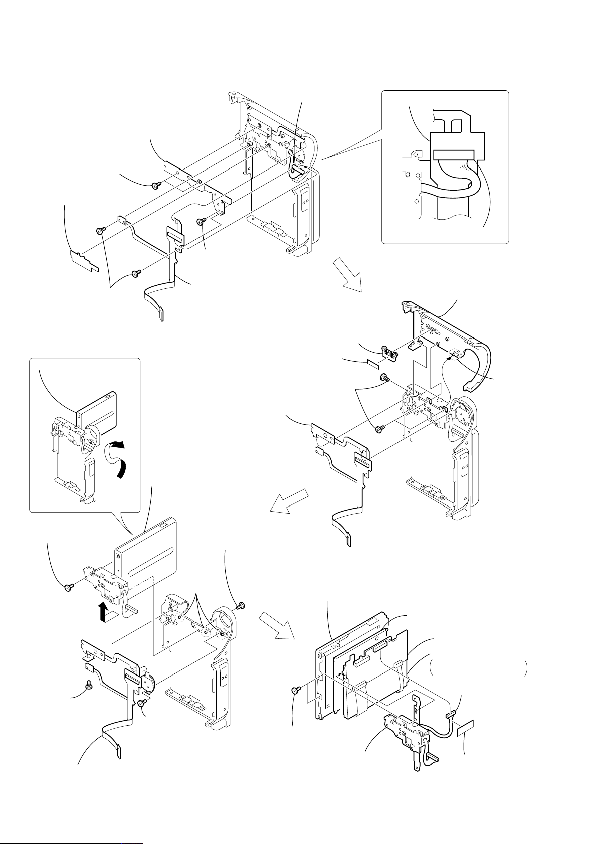
DCR-IP5E/IP7E
2-9. PARTS UNIT (HINGE)
4 T wo screws
(M1.4 × 2.5),
lock ace
1 Waterproof sheet
2 T wo screws
(M1.4 × 2.5),
lock ace
1 Open the LCD unit in the
direction of the arrow A.
6 Menu sheet metal
5 Screw (M1.4 × 2.5),
lock ace
FP-366 flexible
board
3 Harness
(from LCD section)
(17P)
3 R button
2 Muffle sheet (B)
1 Three screws (M1.4 × 2.5),
lock ace
FP-366 flexible board
FP-366 flexible board
Harness (17P)
4 Lens cabinet
(R) assembly
Dowel
3 Screw
(M1.4 × 3)
6 Screw
(M1.4 × 2),
ace
7 FP-366 flexible board
B
A
5 Remove the LCD unit,
parts unit (Hinge) in the
direction of the arrow B.
4 Screw
(M1.4 × 2.5),
lock ace
Three
dowels
2 Screw
(M1.4 × 2.5),
lock ace
Start the removal work afar the LCD section (PD-142 board) has
been removed referring section 2-1.
4 Panel cabinet (R) assembly
Liquid crystal
indicator module
PD-142 board
Back light
Cold cathode fluorescent
tube, BL shield sheet (N)
2 Harness (15P)
1 T ape F
3 T wo screws
(M1.4 × 2.5),
lock ace
PD-142
5 Parts unit
(Hinge)
— 16 —
2-10. BT-003 BOARD (IP7E), CABINET (L) ASSEMBLY
DCR-IP5E/IP7E
7 BT-003
board
6 T wo screws
(M1.4 × 2), ace
(IP7E)
4 MS release knob
3 Compression spring
2 MS knob retainer
assembly
BT-003
5 FP-367 flexible board
(15P)
1 Screw
(M1.4 × 2.5),
lock ace
3 Lens cabinet
(L) section
2 Screw
(M1.4 × 2.5),
lock ace
1 Screw
(M1.4 × 2.5),
lock ace
0 Cabinet (L) assembly
6 Jack cover
8 List strap
7 Screw (M2 × 3)
Note: This screw (M2 × 3) is MEC-processed. If the screw
is are removed once, it cannot be re-used.
When re-assembling, use the new MEC screw.
5 JC retainer
plate
9 Strap bracket
4 Screw
(M1.4 × 2.5),
lock ace
2-11. GRIP CABINET ASSEMBLY, CONTROL SWITCH BLOCK (FK-1900)
3 T wo screws
(M1.4 × 2.5),
lock ace
2 Screw (M1.4 × 2),
lock ace
6 Screw
(M1.4 × 2.5),
lock ace
Control switch block
(FK-1900)
5 T wo screws
(M1.4 × 2.5),
lock ace
4 Screw (M1.4 × 2.5),
lock ace
1 Screw
(M1.4 × 2.5),
lock ace
Dowel
7 T apping screw
(M1.7 × 3.5)
8 Grip arm assembly,
Cabinet (L) joint
2 Grip cabinet assembly
1 Control switch block (FK-1900),
Battery terminal board
— 17 —
DCR-IP5E/IP7E
2
3. REPAIR PARTS LIST
3-1. EXPLODED VIEWS
NOTE:
• -XX, -X mean standardized parts, so they may
have some differences from the original one.
• Items marked “*” are not stocked since they
are seldom required for routine service. Some
delay should be anticipated when ordering these
items.
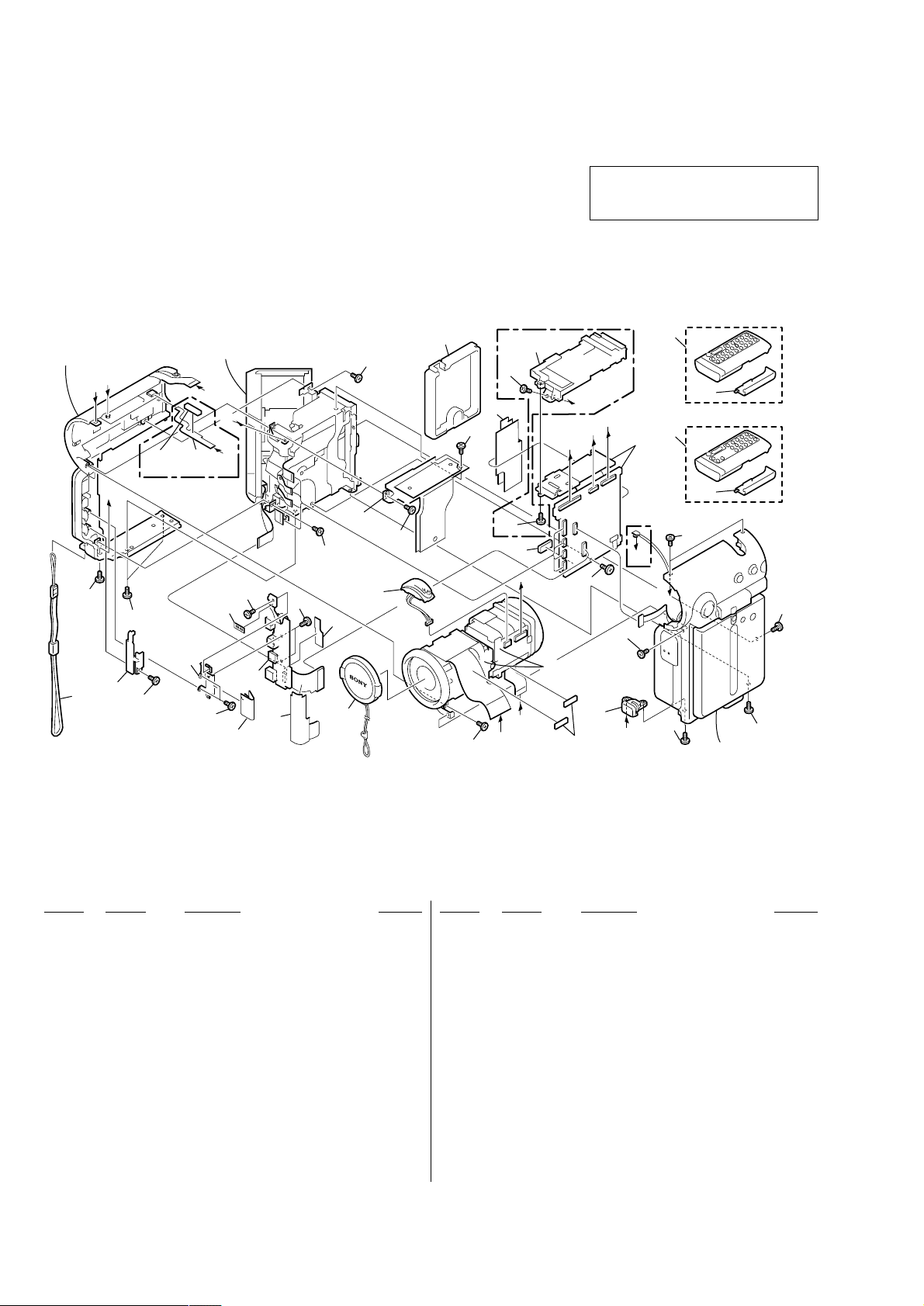
3-1-1. OVERALL SECTION
• The mechanical parts with no reference number
in the exploded views are not supplied.
The components identified by mark 0 or
dotted line with mark 0 are critical for safety.
Replace only with part number specified.
Cabinet (L) section
(See page 23)
F
E
(IP7E)
H
1
1
2
3
1
G Cabinet section
(See page 22)
not
supplied
22
D
4
G
B
23
1
not
supplied
18
21
19
20
1
MIC901
16
17
(IP7E)
24
1
1
8
1
C
G
B
A
11
7
(IP7E)
9
10
(IP5E)
9
10
VC-263
5
1
6
12
D
13
Board
(IP7E)
F
E
1
1
1
LENS-EVF section
(See page 21)
A
C
1
15
not
supplied
H
14
Cabinet (R) section-1,
(See page 19, 20)
1
Ref. No. Part No. Description Remarks Ref. No. Part No. Description Remarks
1 3-389-523-22 SCREW (LOCK ACE)
2 3-069-946-01 PLATE, JC RETAINER
3 3-069-932-01 STRAP, LIST
4 1-682-337-11 FP-367 FLEXIBLE BOARD (IP7E)
5 X-3951-999-1 HEAT SINK ASSY, VC
6 3-713-791-05 SCREW (M1.7)
7 3-069-953-01 SHEET, VC BLIND
8 X-3951-821-1 HOLDER ASSY, MS (IP7E)
8 3-071-914-01 HOLDER, VC PC BOARD (IP5E)
9 1-476-814-21 REMOTE COMMANDER (RMT-818) (IP5E)
9 1-476-815-21 REMOTE COMMANDER (RMT-817) (IP7E)
10 3-053-056-01 LID BATTERY CASE (FOR RMT-817/818)
11 not supplied VC-263B BOARD COMPLETE (SERVICE) (IP5E)
11 not supplied VC-263A BOARD COMPLETE (SERVICE) (IP7E)
12 3-071-191-01 VC SPACER
— 18 —
13 3-069-941-01 HEAD (M1.4) (LOCK ACE)
14 3-071-513-01 0 PART-NO. P2 MAIN M1.4X3
15 3-069-924-01 SCREW, TRIPOD
16 3-069-963-01 SHEET, JK FLEXIBLE PROTECTION
17 X-3951-910-1 CAP ASSY, LENS
18 3-069-941-11 HEAD (M1.4) (LOCK ACE)
19 3-069-959-01 SHEET, JK PC BOARD PROTECTION
20 3-071-189-01 ACE (M1.4)
21 not supplied JK-209 BOARD COMPLETE (IP7E)
21 not supplied JK-209 (L) BOARD COMPLETE (IP5E)
22 X-3951-830-1 BRACKET ASSY, JK
23 3-070-944-01 SHEET,TALLY LIGHT INTERCEPTION
24 3-070-945-01 COVER, BT TERMINAL
MIC901 1-476-816-11 MICROPHONE UNIT
3-1-2. CABINET (R) SECTION-1
DCR-IP5E/IP7E
51
52
(IP7E)
73
53
51
ANT901
53
51
51
B
E
72
51
54
57
53
51
not
supplied
60
73
56
61
58
59
68
C
69
D
53
71
A
62
67
64
not
supplied
66
51
70
55
C
51
B
E
63
Cabinet (R) section-2
(LCD section)
(See page 20)
65
D
A
Ref. No. Part No. Description Remarks Ref. No. Part No. Description Remarks
51 3-389-523-22 SCREW (LOCK ACE)
52 3-069-938-01 SHEET METAL, MENU
53 3-071-189-01 ACE (M1.4)
54 A-7074-962-A FP-366 BOARD COMPLETE
55 3-070-604-01 SCREW (M1.4)
56 3-713-791-05 SCREW (M1.7)
57 3-669-481-02 PIN (DIA. 1), PARALLEL
58 3-069-876-11 SPRING, TORSION
59 3-069-866-11 SHEET METAL, DETECTION (SW)
60 3-069-874-01 LEVER, SWITCHING DETECTION
61 3-069-922-01 BUTTON, R
62 X-3952-071-1 CABINET (R) ASSY (7), LENS
63 3-071-221-01 SHEET, WATERPROOF
64 3-069-879-11 SPACER, PANEL
65 X-3951-813-1 WINDOW ASSY, REMOTE CONTROL (IP7E)
65 X-3952-117-1 WINDOW ASSY (5),REMOTE CONTROL (IP5E)
66 X-3951-812-1 CABINET (R) ASSY
67 3-069-957-01 FOOT (3), RUBBER
68 3-069-875-11 SHEET METAL, PANEL LOCK
69 3-069-873-01 CLAW, PANEL LOCK
70 3-071-888-01 LABEL (ENGLISH), CAUTION
71 3-071-647-01 SHEET (3), HEAT INSULATING
72 3-070-527-01 SHEET (A), MUFFLE
73 3-070-528-01 SHEET (B), MUFFLE
ANT901 1-754-210-11 ANTENNA (2.4GHz) (IP7E)
— 19 —
DCR-IP5E/IP7E
3-1-3. CABINET (R) SECTION-2 (LCD SECTION)
103
109
101
B
C
112
104
102
not
supplied
110
A
113
111
101
101
PD-142
105
LED901
101
101
LCD901
101
106
107
B
C
not
supplied
108
A
Ref. No. Part No. Description Remarks Ref. No. Part No. Description Remarks
101 3-389-523-22 SCREW (LOCK ACE)
102 X-3952-069-1 CABINET (R) ASSY (7), PANEL (IP7E)
102 X-3952-115-1 CABINET (R) ASSY (5), PANEL (IP5E)
103 3-069-923-01 COVER, HINGE
104 1-476-813-11 UNIT PARTS (HINGE)
105 not supplied PD-142 BOARD COMPLETE
106 3-069-989-01 BASE, LCD SW (IP7E)
106 3-069-989-11 BASE, LCD SW (IP5E)
107 3-069-988-01 KNOB, LCD SW
— 20 —
108 X-3952-070-1 CABINET (L) ASSY (7), PANEL (IP7E)
108 X-3952-116-1 CABINET (L) ASSY (5), PANEL (IP5E)
109 3-070-604-01 SCREW (M1.4)
110 3-831-441-11 TAPE (F)
111 3-069-965-01 SPACER (2), PD
112 3-070-533-01 CAP, PAINTING PROTECTION
113 9-911-839-99 SPACER (1), PD
LCD901 not supplied ACX500AKB-J (SERVICE)
0 LED901 not supplied BLOCK (2.5), LIGHT GUIDE PLATE
Note : The components identified by mark 0 or dotted
line with mark 0 are critical for safety.
Replace only with part number specified.
3-1-4. LENS-EVF SECTION
DCR-IP5E/IP7E
155
169
157
156
C
VF-149
153
151
not
supplied
A
A
LD-105
152
not
supplied
B
IC701
172
173
170
171
158
154
167
174
159
160
154
161
LCD902
162
163
168
154
164
166
165
B
C
163
Ref. No. Part No. Description Remarks Ref. No. Part No. Description Remarks
151 3-069-937-01 TAPPING (B1.7X3.5), HEAD
152 X-3951-825-1 PLATE ASSY, VF FIXED
153 not supplied VF-149 BOARD COMPLETE
154 3-389-523-22 SCREW (LOCK ACE)
155 3-071-116-01 SHEET, VF FLEXIBLE PROTECTION
156 X-3951-822-1 RING ASSY, FILTER
157 not supplied 670A (PAL) (CZ) BLOCK ASSY
158 3-069-981-01 CUSHION, BL
159 3-069-980-01 HOLDER, BL
160 3-069-976-01 CUSHION (2), LCD
161 3-069-886-01 CUSHION (1), LCD
162 X-3951-818-1 GUIDE ASSY, VF SLEEVE
163 3-713-791-11 SCREW (M1.7X5), TAPPING, P2
164 3-069-977-01 SLEEVE, VF
165 X-3951-820-1 RING ASSY, VF
166 X-3951-817-1 LENS ASSY, VF
167 not supplied SCREW (B1.7) TAPPING
168 3-069-930-01 SHEET, VF GUARD
169 3-713-791-05 SCREW (M1.7)
170 3-070-948-01 CUSHION, LENS
171 3-069-940-01 SHEET METAL, BL RETAINER
172 not supplied RVBBER (S) SEAL
173 not supplied FILTER BLOCK OPTICAL
174 not supplied BLOCK(0.44), LIGHT GUIDE PLATE
IC701 not supplied ICX281DKF-13 (CCD IMAGER)
LCD902 not supplied LCX033AN-J (SERVICE)
— 21 —
DCR-IP5E/IP7E
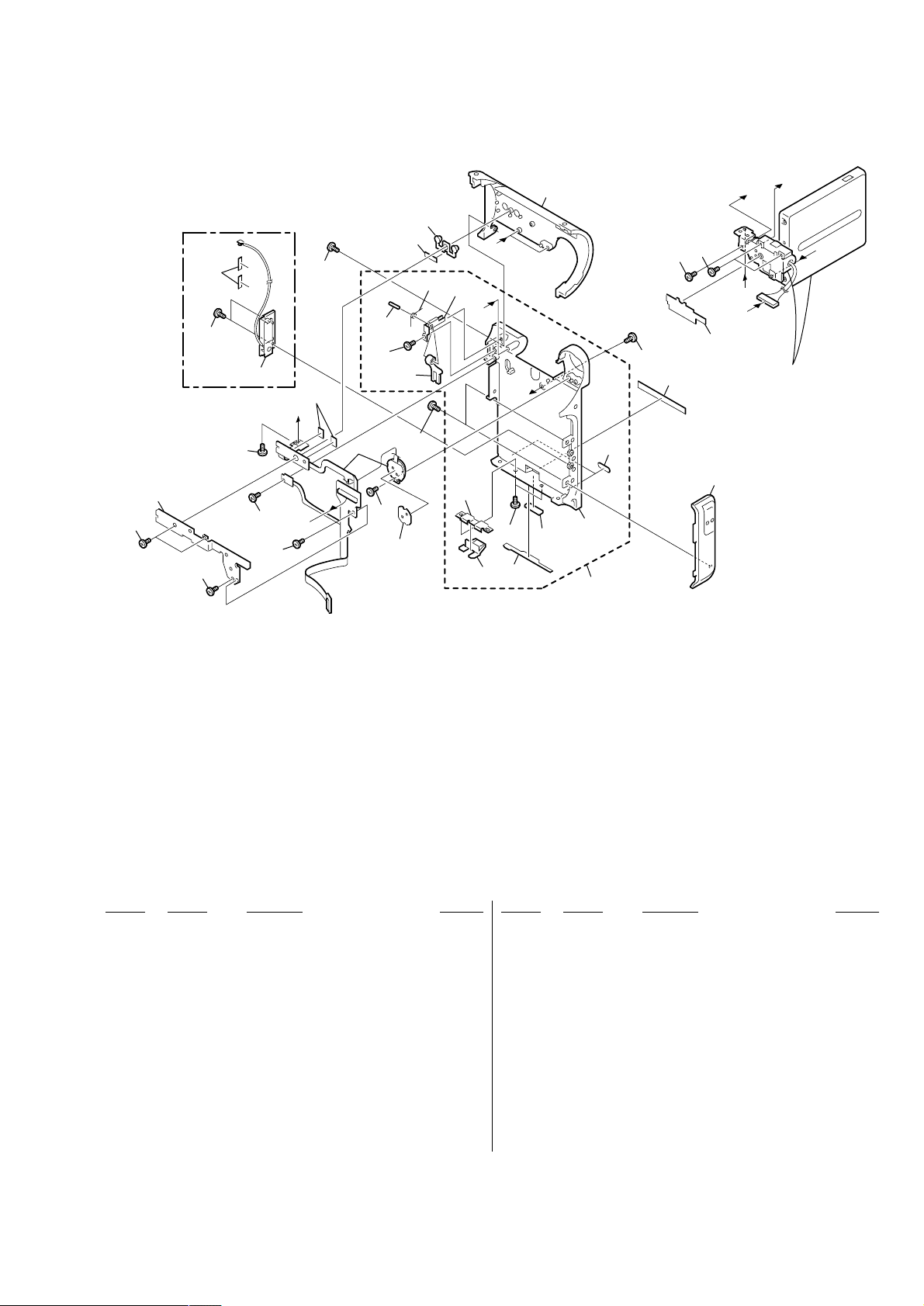
3-1-5. G CABINET SECTION
201
203
not
supplied
201
202
207
201
: BT001 (Lithium battery) FK-1900 control switch block on the mount position.
205
204
213
BT901
209
206
A
B
C
BT001
210
211
212
201
B
213
204
A
not
supplied
204
C
214
208
204
215
Mechanism deck
204
212
Ref. No. Part No. Description Remarks Ref. No. Part No. Description Remarks
201 3-389-523-23 SCREW (LOCK ACE)
202 3-069-891-01 SLIDER, G LOCK
203 3-069-892-01 TALLY, POWER (IP7E)
203 3-069-892-11 TALLY, POWER (IP5E)
204 3-389-523-22 SCREW (LOCK ACE)
205 3-069-890-01 BUTTON, G LOCK RELEASE
206 3-069-962-01 SHEET, CHG BLIND
207 X-3951-865-1 RELEASE ASSY, BT
208 3-069-947-01 SLIDER, CASSETTE COMPARTMENT
209 X-3952-067-1 CABINET ASSY (7E), GRIP (IP7E)
209 X-3952-113-1 CABINET ASSY (5E), GRIP (IP5E)
210 3-069-950-01 SHEET, BT TERMINAL BLIND
211 1-476-812-11 SWITCH BLOCK, CONTROL (FK-1900)
212 3-071-189-01 ACE (M1.4)
213 3-713-791-05 SCREW (M1.7)
214 3-069-928-01 JOINT, CABINET (L)
215 X-3951-816-1 ARM ASSY, GRIP
BT001 1-756-102-11 BATTERY, LITHIUM SECONDARY
BT901 1-694-843-11 TERMINAL BOARD, BATTERY
— 22 —
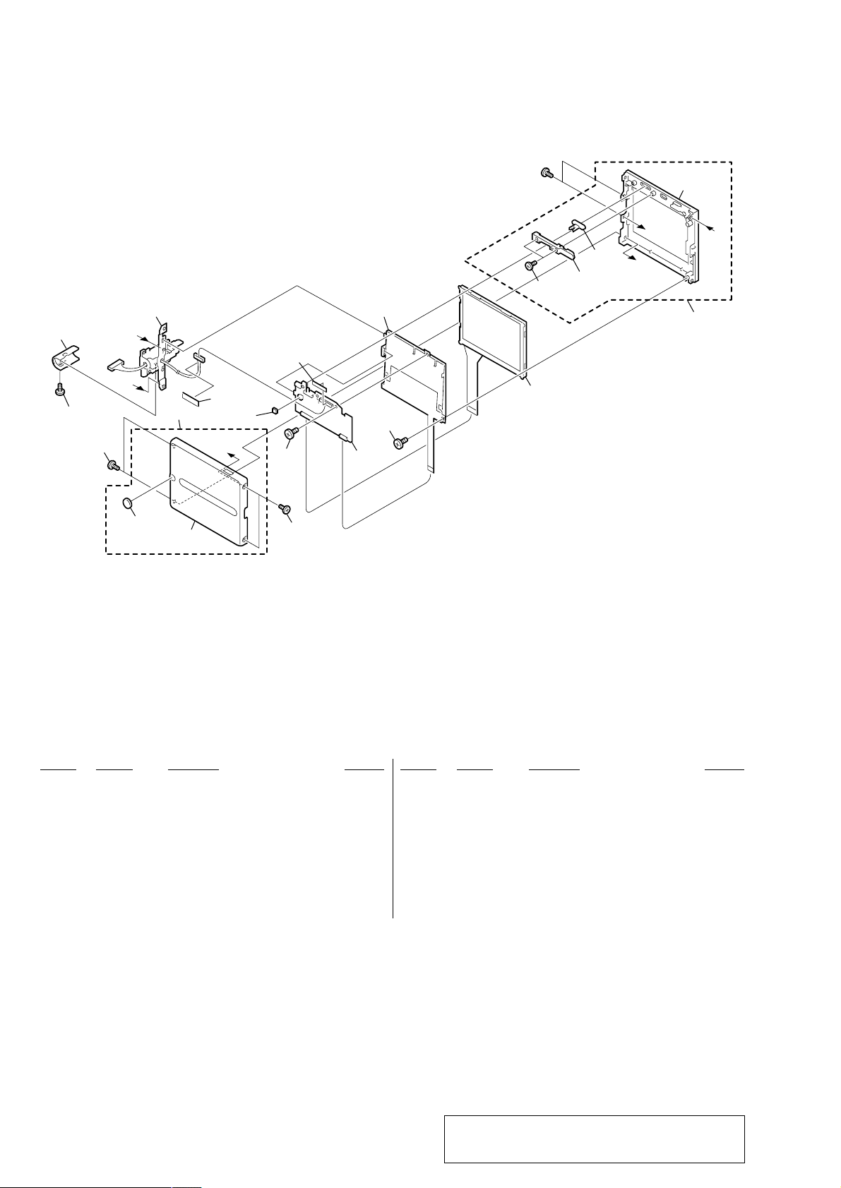
3-1-6. CABINET (L) SECTION
DCR-IP5E/IP7E
261
255
257
not
256
supplied
255
254
Note
251
253
Note: This screw (M2 × 3) is MEC-processed. If the screw
is are removed once, it cannot be re-used.
When re-assembling, use the new MEC screw.
252
260
258
259
255
266
267
SP901
BT-003
262
not
supplied
265
263
255
(IP7E)
255
264
Ref. No. Part No. Description Remarks Ref. No. Part No. Description Remarks
251 3-069-888-01 FOOT, RUBBER
252 3-069-885-01 BRACKET, STRAP
253 3-069-956-01 FOOT (2), RUBBER
254 3-724-455-41 SCREW
255 3-389-523-22 SCREW (LOCK ACE)
256 3-069-883-01 COVER, JACK
257 X-3952-068-1 CABINET (L) ASSY (IP7E)
257 X-3952-174-1 CABINET (L) ASSY (IP5E)
258 3-069-881-01 KNOB, MS RELEASE (IP7E)
259 3-062-142-01 SPRING, COMPRESSION (IP7E)
260 3-069-945-11 CABINET (L), LENS
261 1-476-811-21 SWITCH BLOCK, CONTROL (CF-1900)
262 3-070-947-01 CUSHION, SP
263 3-069-983-01 RETAINER, SP
264 X-3951-827-1 RETAINER ASSY, MS KNOB (IP7E)
264 3-069-882-02 MS KNOB, RETAINER (IP5E)
265 not supplied BT-003 BOARD COMPLETE (IP7E)
266 X-3951-819-1 CASE ASSY, BT SHIELD (IP7E)
267 3-071-189-01 ACE (M1.4)
SP901 1-529-857-11 SPEAKER (1.6 CM)
— 23 —
DCR-IP5E/IP7E
English
Main Features
Taking moving or still images, and playing them back
•Recording a picture on a tape (p. 38)
•Recording a still image on a tape (p. 61)
•Playing back a tape (p. 51)
•Recording a still image on a “Memory Stick” (p. 149) (DCR-IP7E only)
•Recording moving pictures on a “Memory Stick” (p. 160) (DCR-IP7E only)
•Viewing a still image recorded on a “Memory Stick” (p. 174) (DCR-IP7E only)
•Viewing a moving picture on a “Memory Stick” (p. 179) (DCR-IP7E only)
Capturing images on your computer
•Viewing an image recorded on a tape using your computer via the i.LINK cable (p. 199)
•Viewing an image recorded on a “Memory Stick” using your computer via the USB cable (p. 201)
(DCR-IP7E only)
Accessing the Internet via a Bluetooth device (not supplied) (DCR-IP7E only)
•Accessing the Internet and sending/receiving your e-mail. For details, refer to the network function
operating instructions supplied with your camcorder.
Other uses
Functions to adjust exposure in recording mode
•Back light (p. 47)
•PROGRAM AE (p. 75)
•White balance (p. 78)
•Adjusting the exposure manually (p. 80)
2. GENERAL
Main Features
Functions to give an effect to your recordings
•Digital zoom (p. 124)
The default setting is set to OFF. (To zoom greater than 10×, set up the D ZOOM item in the menu
settings.)
•Fader (p. 66)
•Picture effect (p. 69)
•Digital effect (p. 71)
•Title (p. 108, 116)
•MEMORY MIX (p. 166) (DCR-IP7E only)
Functions to give a natural appearance to your recordings
•Manual focus (p. 82)
•Landscape mode (p. 75)
Functions used after recording
•END SEARCH (p. 50)
•DATA CODE (p. 54)
•Multi-picture search (p. 88)
•Title search (p. 93)
•Date search (p. 95)
•Photo search (p. 97)
This section is extracted from
instruction manual.
4
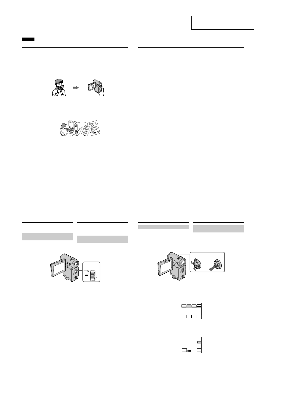
Introduction – Basic
operations
This section describes the basic operations used
to control and ways to operate the camcorder.
How to turn on the power and
select the mode
To supply power for the camcorder, see “Step 1
Preparing the power supply” on page 25.
(1)Slide the POWER switch down while pressing
the small green button, then release your
finger.
The camcorder is turned on, and then the
camcorder turns to the CAMERA mode so
that the CAMERA lamp lights up.
(2)Slide the POWER switch down. Each time you
slide it down, the mode changes as follows
and corresponding mode lamp also lights up.
CAMERA Use this mode when you record on
a tape.
MEMORY/NETWORK (DCR-IP7E only)
MEMORY: Use this mode when you record
on a “Memory Stick”, or play
back or edit a image in a
“Memory Stick”.
NETWORK: Use this mode when you use
the network function. For
details, refer to the supplied
network function operating
VCRUse this mode when you play back or
8
instructions.
edit an image recorded on a tape or
“Memory Stick” (A “Memory Stick” can
only be used with the DCR-IP7E).
Bвeдeниe – Ocновныe
опepaции
B этом paздeлe опиcывaютcя оcновныe
опepaции, иcпользyeмыe для yпpaвлeния, и
cпоcобы paботы c видeокaмepой.
Кaк включить питaниe и
выбpaть peжим
Чтобы включить питaниe видeокaмepы, cм.
“Пyнкт 1 Подготовкa иcточникa питaния” нa
cтp. 25.
1,2
POWER
CAMERA
MEMORY/
(CHG)
NETWORK
OFF
VCR
ON
MODE
(1)Пepeдвиньтe пepeключaтeль POWER
вниз, нaжaв мaлeнькyю зeлeнyю кнопкy,
зaтeм отпycтитe.
Bидeокaмepa включитcя, зaтeм пepeйдeт
в peжим CAMERA, и зaгоpитcя индикaтоp
CAMERA.
(2)Пepeдвиньтe пepeключaтeль POWER
вниз. Пpи кaждом пepeдвижeнии eго вниз
зaгоpaeтcя cоотвeтcтвyющий индикaтоp
peжимa, и peжим измeняeтcя cлeдyющим
обpaзом.
CAMERA Иcпользyйтe этот peжим пpи
зaпиcи нa лeнтy.
MEMORY/NETWORK (только модeль
DCR-IP7E)
MEMORY: Иcпользyйтe этот peжим пpи
зaпиcи нa “Memory Stick”, a
тaкжe пpи воcпpоизвeдeнии
или peдaктиpовaнии
изобpaжeния нa “Memory
Stick”.
NETWORK: Иcпользyйтe этот peжим пpи
иcпользовaнии фyнкции
Network. Подpобнyю
инфоpмaцию о фyнкции
Network cм. в пpилaгaeмой
инcтpyкции по экcплyaтaции.
VCR Иcпользyйтe этот peжим пpи
воcпpоизвeдeнии или
peдaктиpовaнии изобpaжeния,
зaпиcaнного нa лeнтe или “Memory
Stick” (“Memory Stick” можно
иcпользовaть только для модeли
DCR-IP7E).
Introduction – Basic operations
How to use the control button
Most of the operations are carried out using the
control button. Select a button displayed on the
screen using the control button, then press the
centre z on the control button.
(1)Press v/V/b/B on the control button
repeatedly to select the desired button
displayed on the screen.
The selected button turns orange.
PAGE1 PAGE2 PAGE3
LCD
BRT
(2)Press the centre z on the control button to
enter the setting.
Repeat steps 1 and 2 to execute the function.
Bвeдeниe – Ocновныe опepaции
Кaк иcпользовaть кнопкy
yпpaвлeния
Большинcтво опepaций пpоизводятcя c
помощью кнопки yпpaвлeния. Bыбepитe
кнопкy, отобpaжaeмyю нa экpaнe, c помощью
кнопки yпpaвлeния, зaтeм нaжмитe нa цeнтp
z нa кнопкe yпpaвлeния.
12
(1)Haжимaя v/V/b/B нa кнопкe yпpaвлeния,
выбepитe нyжнyю кнопкy, отобpaжaeмyю
нa экpaнe.
Bыбpaннaя кнопкa cтaнeт оpaнжeвой.
EXIT
END
TITLE
VOL
SCH
(2)Haжмитe нa цeнтp z нa кнопкe
yпpaвлeния для вводa ycтaновки.
Повтоpитe пyнкты 1 и 2 для выполнeния
фyнкции.
OK
LCD BRT
– +
5
Getting started/Подготовкa к экcплyaтaции
9
1-24
DCR-IP5E/IP7E
Introduction – Basic operations
The procedure above is referred to as “Select
[XXXX], then press the centre z on the control
button” in this operating instructions.
When an item is selected
A green bar appears above the item.
If certain items are not available
The colour of those items changes to grey.
How to use the FN screen
If FN is not displayed on the screen, press
DISPLAY or the centre z on the control button.
DISPLAY
(1)Select FN with v/V/b/B on the control
button, then press the centre z. The FN
screen appears.
In CAMERA mode/B peжимe CAMERA
(2)To change the page, select PAGE1, PAGE2, or
PAGE3 with v/V/b/B on the control button,
then press the centre z. The PAGE1/PAGE2/
PAGE3 screen appears.
(3)Select the desired item with v/V/b/B on the
control button, then press the centre z. The
screen that corresponds to that button will
appear, or that function will be executed.
10
Bвeдeниe – Ocновныe опepaции
Bышeопиcaннaя пpоцeдypa в инcтpyкции по
экcплyaтaции нaзывaeтcя “Bыбepитe
[XXXX], зaтeм нaжмитe нa цeнтp z нa
кнопкe yпpaвлeния”.
Пpи выбоpe элeмeнтa
Haд ним появляeтcя зeлeнaя полоca.
Ecли кaкиe-то элeмeнты нeдоcтyпны
Цвeт этиx элeмeнтов измeняeтcя нa cepый.
Кaк иcпользовaть экpaн FN
Ecли нa экpaнe нe отобpaжaeтcя FN,
нaжмитe DISPLAY или нa цeнтp z нa кнопкe
yпpaвлeния.
1–3
(1)Bыбepитe FN c помощью v /V/b/B нa
кнопкe yпpaвлeния, зaтeм нaжмитe нa
цeнтp z. Появитcя экpaн FN.
PAGE1 PAGE2 PAGE3
MENU FOCUS
FADER SELF
FN
(2)Чтобы cмeнить cтpaницy, выбepитe
(3)Bыбepитe тpeбyeмый элeмeнт c помощью
EXIT
MEM
EXPO–
MIX
SURE
TIMER
PAGE1, PAGE2 или PAGE3 c помощью v/
V/b/B нa кнопкe yпpaвлeния, зaтeм
нaжмитe нa цeнтp z. Появитcя экpaн
PAGE1/PAGE2/PAGE3.
v/V/b/B нa кнопкe yпpaвлeния, зaтeм
нaжмитe нa цeнтp z. Появитcя экpaн,
cоотвeтcтвyющий этой кнопкe, или бyдeт
выполнeнa фyнкция.
Introduction – Basic operations
To return to the FN screen
Select OK, then RETURN, or END
with v/V/b/B on the control button, then press
the centre z. Next, select EXIT with v/V/b/B
on the control button, then press the centre z.
To execute settings
Select OK with v/V/b/B on the control
button, then press the centre z. The display
returns to the PAGE1/PAGE2/PAGE3 screen.
To cancel settings
Select OFF or AUTO with v/V/b/B on the
control button, then press the centre z. The
display returns to the PAGE1/PAGE2/PAGE3
screen.
The screen buttons on the PAGE1/PAGE2/
PAGE3 screen
In CAMERA mode
PAGE1 MENU, FADER, SELFTIMER, MEM
MIX*, EXPOSURE, FOCUS
PAGE2 LCD BRT, VOL, END SCH, TITLE
PAGE3 DIG EFFT, COUNT RESET
In VCR mode
PAGE1 MENU, VOL, TITLE, MULTI SRCH, x/
PB*, m *, BX *, M *
PAGE2 LCD BRT, DIG EFFT, END SCH,
x/ PB*, m *, BX *, M *
PAGE3
DATA CODE, COUNT RESET, qREC
CTRL, x/ PB*, m *, BX *,
M *
* (DCR-IP7E only)
See page 142 for the MEMORY/NETWORK
mode (DCR-IP7E only).
To turn on/off the screen buttons
Press DISPLAY. However, the finder can be used
only in mirror mode.
A screen where the FN button is displayed is
referred to as the FN screen in this operating
instructions.
Bвeдeниe – Ocновныe опepaции
Для возвpaтa к экpaнy FN
Bыбepитe OK, зaтeм RETURN или
END c помощью v/V/b/B нa кнопкe
yпpaвлeния, зaтeм нaжмитe нa цeнтp z.
Зaтeм выбepитe EXIT c помощью v/V/b/B нa
кнопкe yпpaвлeния, зaтeм нaжмитe нa цeнтp
z.
Для выполнeния ycтaновок
Bыбepитe OK c помощью v/V/b/B нa
кнопкe yпpaвлeния, зaтeм нaжмитe нa цeнтp
z. Oтобpaжeниe вepнeтcя к экpaнy PAGE1/
PAGE2/PAGE3.
Для отмeны ycтaновок
Bыбepитe OFF или AUTO c помощью v/V/
b/B нa кнопкe yпpaвлeния, зaтeм нaжмитe нa
цeнтp z. Oтобpaжeниe вepнeтcя к экpaнy
PAGE1/PAGE2/PAGE3.
Экpaнныe кнопки нa экpaнe PAGE1/PAGE2/
PAGE3
B peжимe CAMERA
PAGE1 MENU, FADER, SELFTIMER, MEM MIX*,
EXPOSURE, FOCUS
PAGE2 LCD BRT, VOL, END SCH, TITLE
PAGE3 DIG EFFT, COUNT RESET
B peжимe VCR
PAGE1 MENU, VOL, TITLE, MULTI SRCH, x/
PB*, m *, BX *, M *
PAGE2 LCD BRT, DIG EFFT, END SCH,
x/ PB*, m *, BX *, M *
PAGE3 DATA CODE, COUNT RESET,
CTRL, x/ PB*, m *, BX *,
M
* (только модeль DCR-IP7E)
Инфоpмaцию о peжимe MEMORY/NETWORK
cм. нa cтp. 142 (только модeль DCR-IP7E).
Чтобы включить/выключить экpaнныe
кнопки
Haжмитe кнопкy DISPLAY. Oднaко
видоиcкaтeль можно иcпользовaть только в
зepкaльном peжимe.
B этой инcтpyкции по экcплyaтaции экpaн,
нa котоpом pacположeнa кнопкa FN,
нaзывaeтcя экpaном FN.
*
q
REC
Getting started/Подготовкa к экcплyaтaции
11
Englsih
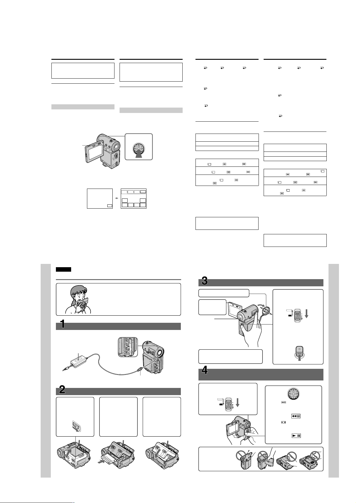
Quick Start Guide
This guide introduces you to the basic operations for
recording/playback. See the page in parentheses “()” for
more information.
Connecting the mains lead (p. 30)
Use the battery pack when using your camcorder outdoors (p. 25).
AC power adaptor (supplied)
Quick Start Guide
Inserting a cassette (p. 36)
1 Slide OPEN/ZEJECT
in the direction of the
arrow and open the
lid.
Open the jack
cover.
2 Push the middle
portion of the back of
the cassette to insert.
Insert it the cassette
in a straight line
deeply into the
cassette compartment
with the window
facing out.
Connect the plug with its v
mark facing the lens side.
3 Close the cassette
compartment by
pushing down the
cassette lid halfway.
After the cassette
compartment goes
down completely,
close the lid until it
clicks.
Recording a picture
1
Remove the lens cap.
2
Press OPEN
to open the
LCD panel.
Viewfinder
When the LCD panel
is closed, pull out the
viewfinder until it
clicks and use it to
monitor your
recording.
When you purchase your camcorder, the clock
is not set up yet. Set up the clock before
recording (p. 32).
Monitoring the playback picture on the LCD
screen
(p. 51)
1
Set the POWER switch to VCR.
The VCR lamp lights up.
CAMERA
MEMORY/
NETWORK
POWER
(CHG)
OFF
VCR
ON
MODE
(p. 38)
3
4
2
Select , then press the centre z
on the control button to rewind the
tape.
3
Select , then press the centre z
on the control button to start
playback.
Set the POWER switch to
CAMERA.
The CAMERA lamp lights up.
POWER
CAMERA
MEMORY/
(CHG)
NETWORK
OFF
VCR
ON
MODE
Press START/STOP. Your
camcorder starts recording. To
stop recording, press START/
STOP again.
START/STOP
Quick Start Guide
16
— 25 —
NOTE
Do not pick up your
camcorder by holding
the viewfinder, the
LCD panel, the battery
pack, or the jack cover.
17
 Loading...