

Sony DAV-DZ555M User Manual
2-895-970-E2(1)
DVD Home Theatre
System
Operating Instructions
DAV-DZ555M
©2007 Sony Corporation
WARNING
To reduce the risk of fire or electric
shock, do not expose this apparatus to
rain or moisture.
Caution – The use of optical instruments
with this product will increase eye
hazard.
Do not install the appliance in a confined space, such
as a bookcase or built-in cabinet.
To prevent fire, do not cover the ventilation of the
apparatus with news papers, table-cloths, curtains, etc.
And don’t place lighted candles on the apparatus.
To prevent fire or shock hazard, do not place objects
filled with liquids, such as vases, on the apparatus.
Do not expose the battery to excessive heat such as
direct sunlight, fire, or the like.
Don’t throw away the battery with
general house waste, dispose of it
correctly as chemical waste.
This appliance is
classified as a CLASS 1
LASER product. This
marking is located on the
rear exterior.
Disposal of Old
Electrical & Electronic
Equipment (Applicable
in the European Union
and other European
countries with separate
collection systems)
This symbol on the produ ct or on
its packaging indicates that this
product shall not be treated as household waste. Instead
it shall be handed over to the applicable collection
point for the recycling of electrical and electronic
equipment. By ensuring this product is disposed of
correctly, you will help prevent potential negative
consequences for the environment and human health,
which could otherwise be caused by inappropriate
waste handling of this product. The recycling of
materials will help to conserve natural resources. For
more detailed information about recycling of this
product, please contact your local Civic Office, your
household waste disposal service or the shop where
you purchased the product.
Precautions
On power sources
• AC power cord (mains lead) must be changed only at
the qualified service shop.
• The unit is not disconnected from the AC power
source (mains) as long as it is connected to the wall
outlet (mains), even if the unit itself has been turned
off.
• Install this system so that the AC power cord (mains)
can be unplugged from the wall socket immediately
in the event of trouble.
Welcome!
Thank you for purchasing Sony DVD Home
Theatre System. Before operating this system,
please read this manual thoroughly and retain it
for future reference.
GB
2

Table of Contents
d
Welcome!................................................2
About This Manual .................................5
This System Can Play the Following
Discs .................................................5
Getting Started – BASIC –
Step 1: Assembling
the Speakers ............................. 9
Step 2: Connecting the System and
TV ............................................. 14
Step 3: Positioning the System... 18
Step 4: Performing the Quick
Setup........................................ 19
Getting Started
– ADVANCED –
Turning off the Demonstration .............22
Installing the Speakers on a Wall..........23
Connecting the TV (Advanced) ............24
Connecting Other Components.............28
Basic Operations
Playing Discs ................................ 30
Enjoying the Radio or Other
Components............................ 31
Enjoying TV or VCR Sound from All
Speakers.................................. 32
Selecting the Movie or Music
Mode ........................................ 33
Sound Adjustments
Enjoying Surround Sound by Using Sound
Field ................................................34
Various Functions for Playing
Discs
Searching for a Particular Point on
a Disc ..............................................36
(Scan, Slow-motion Play, Freeze
Frame)
Searching for a Title/Chapter/Track/
Scene, etc........................................37
Searching by Scene...............................38
(Picture Navigation)
Resuming Playback from the Point Where
You Stopped the Disc .....................38
(Resume Play)
Creating Your Own Program................ 39
(Program Play)
Playing in Random Order..................... 41
(Shuffle Play)
Playing Repeatedly............................... 42
(Repeat Play)
Using the DVD’s Menu........................ 43
Changing the Sound.............................. 43
Selecting [ORIGINAL] or [PLAY LIST]
on a DVD-R/DVD-RW.................. 45
Viewing Information About the Disc ... 46
Changing the Angles ............................ 48
Displaying the Subtitles........................ 48
Adjusting the Delay Between the Picture
and Sound....................................... 49
(A/V SYNC)
About MP3 Audio Tracks and JPEG
Image Files ..................................... 49
Playing DATA CDs or DATA DVDs with
MP3 Audio Tracks and JPEG Image
Files ................................................ 51
Playing Audio Tracks and Images as a
Slide Show with Sound .................. 53
Enjoying DivX® Videos ...................... 55
Playing VIDEO CDs with PBC Functions
(Ver.2.0) ......................................... 57
(PBC Playback)
Tuner Functions
Presetting Radio Stations...................... 58
Listening to the Radio........................... 59
Other Operations
Controlling the TV with the Supplied
Remote ........................................... 61
Using the THEATRE SYNC Function. 61
Enjoying Karaoke................................. 62
Using the Sound Effect......................... 66
Using the Sleep Timer .......................... 66
Changing the Brightness of the Front
Panel Display.................................. 67
Using the DIGITAL MEDIA PORT
Adapter........................................... 67
Deactivating the Buttons on the Unit ... 68
(Child Lock)
continue
GB
3

Advanced Settings and
Adjustments
Locking Discs .......................................69
(CUSTOM PARENTAL
CONTROL, PARENTAL
CONTROL)
Getting Optimal Surround Sound for a
Room ..............................................72
(SPEAKER FORMATION)
Calibrating the Appropriate Settings
Automatically .................................74
(AUTO CALIBRATION)
Using the Setup Display........................76
Setting the Display or Sound Track
Language ........................................78
[LANGUAGE SETUP]
Settings for the Display.........................78
[SCREEN SETUP]
Custom Settings ....................................80
[CUSTOM SETUP]
Settings for the Speakers.......................81
[SPEAKER SETUP]
Returning to the Default Settings..........84
Additional Information
Precautions............................................85
Notes about the Discs............................86
Troubleshooting....................................86
Self-diagnosis Function ........................90
(When letters/numbers appear in
the display)
Specifications........................................91
Glossary ................................................92
Language Code List..............................95
Index to Parts and Controls...................96
Guide to the Control Menu Display......99
DVD Setup Display List.....................103
System Menu List...............................104
Index ...................................................105
GB
4
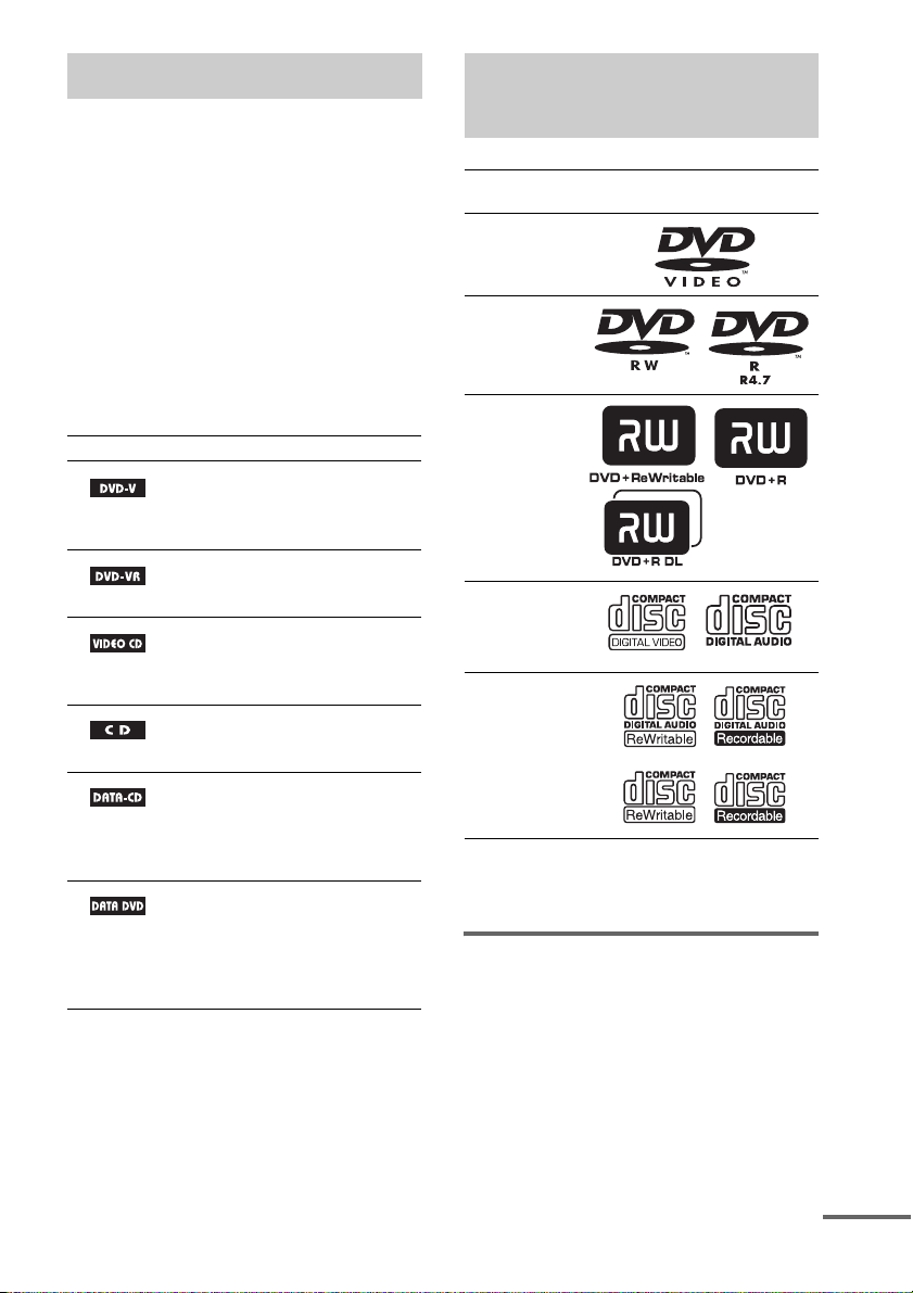
About This Manual
d
This System Can Play the
• The instructions in this manual describe the
controls on the remote. You can also use the
controls on the unit if they have the same or
similar names as those on the remote.
• The Control Menu items may vary depending
on the area.
• “DVD” may be used as a general term for
DVD VIDEOs, DVD+RWs/DVD+Rs, and
DVD-RWs/DVD-Rs.
• Measurements are expressed in feet (ft) for
North American models.
• The following symbols are used in this
manual.
Symbol Meaning
Functions available for DVD
VIDEOs, DVD-Rs/DVD-RWs in
video mode, and DVD+Rs/
DVD+RWs
Functions available for DVD-Rs/
DVD-RWs in VR (Video
Recording) mode
Functions available for VIDEO
CDs (including Super VCDs or CDRs/CD-RWs in video CD format or
Super VCD format)
Functions available for music CDs
or CD-Rs/CD-RWs in music CD
format
Functions available for DATA CDs
(CD-ROMs/CD-Rs/CD-RWs)
containing MP3
JPEG image files, and DivX
video files
Functions available for DATA
DVDs (DVD-ROMs/DVD-Rs/
DVD-RWs/DVD+Rs/DVD+RWs)
containing MP3
JPEG image files, and DivX
video files
1)
MP3 (MPEG1 Audio Layer 3) is a standard format
defined by ISO/MPEG which compresses audio data.
2)
DivX® is a video file compression technology,
developed by DivX, Inc.
3)
DivX, DivX Certified, and associated logos are
trademarks of DivX, Inc. and are used under license.
1)
audio tracks,
1)
audio tracks,
2)3)
2)3)
Following Discs
Format of
discs
DVD VIDEO
DVD-RW/
DVD-R
DVD+RW/
DVD+R
VIDEO CD
(Ver. 1.1 and
2.0 discs)/
Audio CD
CD-RW/CD-R
(audio data)
(MP3 files)
(JPEG files)
“DVD-RW,” “DVD+RW,” “DVD+R,”
“DVD VIDEO,” and the “CD” logos are trademarks.
Note about CDs/DVDs
The system can play CD-ROMs/CD-Rs/CDRWs recorded in the following formats:
– audio CD format
– VIDEO CD format
– MP3 audio tracks, JPEG image files, and
DivX video files of format conforming to ISO
9660 Level 1/Level 2, or its extended format,
Joliet
Disc logo
continue
GB
5

The system can play DVD-ROMs/DVD+RWs/
DVD-RWs/DVD+Rs/DVD-Rs recorded in the
following formats:
– MP3 audio tracks, JPEG image files, and
DivX video files of format conforming to
UDF (Universal Disc Format)
Example of discs that the system cannot play
The system cannot play the following discs:
• CD-ROMs/CD-Rs/CD-RWs other than those
recorded in the formats listed on page 5
• CD-ROMs recorded in PHOTO CD format
• Data part of CD-Extras
• DVD Audios
• Super Audio CD
• DATA DVDs that do not contain MP3 audio
tracks, JPEG image files, or DivX video files
•DVD-RAMs
Also, the system cannot play the following
discs:
• A DVD VIDEO with a different region code
(page 6, 94)
• A disc that has a non-standard shape (e.g.,
card, heart)
• A disc with paper or stickers on it
• A disc that has the adhesive of cellophane tape
or a sticker still left on it
Notes about CD-R/CD-RW/DVD-R/
DVD-RW/DVD+R/DVD+RW
In some cases, CD-R/CD-RW/DVD-R/DVDRW/DVD+R/DVD+RW cannot be played on
this system due to the recording quality or
physical condition of the disc, or the
characteristics of the recording device and
authoring software.
The disc will not play if it has not been correctly
finalized. For more information, see the
operating instructions for the recording device.
Note that some playback functions may not
work with some DVD+RWs/DVD+Rs, even if
they have been correctly finalized. In this case,
view the disc by normal playback. Also some
DATA CDs/DATA DVDs created in Packet
Write format cannot be played.
Music discs encoded with
copyright protection
technologies
This product is designed to play back discs that
conform to the Compact Disc (CD) standard.
Recently, various music discs encoded with
copyright protection technologies are marketed
by some record companies. Please be aware that
among those discs, there are some that do not
conform to the CD standard and may not be
playable by this product.
Note on DualDiscs
A DualDisc is a two sided disc product which
mates DVD recorded material on one side with
digital audio material on the other side.
However, since the audio material side does not
conform to the Compact Disc (CD) standard,
playback on this product is not guaranteed.
About Multi Session CD
• This system can play Multi Session CDs when
an MP3 audio track is contained in the first
session. Any subsequent MP3 audio tracks
recorded in later sessions can also be played
back.
• This system can play Multi Session CDs when
a JPEG image file is contained in the first
session. Any subsequent JPEG image files
recorded in later sessions can also be played
back.
• If audio tracks and images in music CD format
or video CD format are recorded in the first
session, only the first session will be played
back.
Region code
Your system has a region code printed on the
rear of the unit and will only play DVDs labeled
with the same region code.
DVD VIDEOs labeled will also play on this
system.
If you try to play any other DVD VIDEO, the
message [Playback prohibited by area
limitations.] will appear on the TV screen.
Depending on the DVD VIDEO, no region code
ALL
GB
6

indication may be given even though playing the
DVD VIDEO is prohibited by area restrictions.
Note about playback operations of DVDs and VIDEO CDs
Some playback operations of DVDs and VIDEO
CDs may be intentionally set by software
producers. Since this system plays DVDs and
VIDEO CDs according to the disc contents the
software producers designed, some playback
features may not be available. Be sure to read the
operating instructions supplied with the DVDs
or VIDEO CDs.
Copyrights
This product incorporates copyright protection
technology that is protected by U.S. patents and
other intellectual property rights. Use of this
copyright protection technology must be
authorized by Macrovision, and is intended for
home and other limited viewing uses only unless
otherwise authorized by Macrovision. Reverse
engineering or disassembly is prohibited.
This system incorporates with Dolby* Digital
and Dolby Pro Logic (II) adaptive matrix
surround decoder and the DTS** Digital
Surround System.
* Manufactured under license from Dolby
Laboratories.
“Dolby”, “Pro Logic”, and the double-D symbol are
trademarks of Dolby Laboratories.
** Manufactured under license from DTS, Inc.
“DTS” and “DTS Digital Surround” are registered
trademarks of DTS, Inc.
GB
7
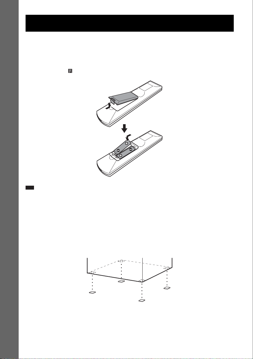
Getting Started – BASIC –
See Unpacking in Specifications, page 91.
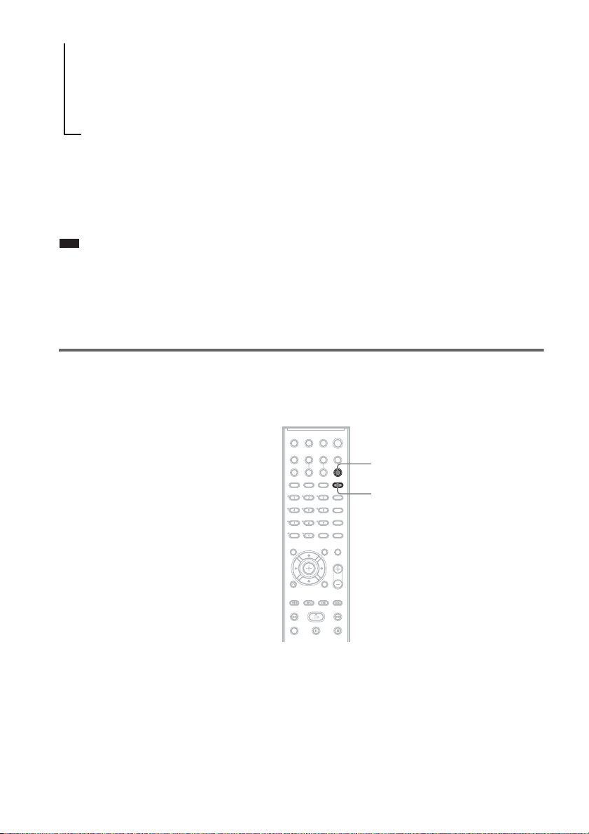
Inserting batteries into the remote
You can control the system using the supplied remote. Insert two R6 (size AA) batteries by matching
the 3 and # ends on the batteries to the markings inside the compartment. To use the remote, point it
at the remote sensor on the unit.
Getting Started – BASIC –
Note
• Do not leave the remote in an extremely hot or humid place.
• Do not use a new battery with an old one.
• Do not drop any foreign object into the remote casing, particularly when replacing the batteries.
• Do not expose the remote sensor to direct sunlight or lighting apparatus. Doing so may cause a malfunction.
• If you do not intend to use the remote for an extended period of time, remove the batteries to avoid possible damage
from battery leakage and corrosion.
Attaching the foot pads to the subwoofer
Attach the supplied foot pads to the bottom of the subwoofer to stabilize the subwoofer and prevent it
from slipping.
GB
8
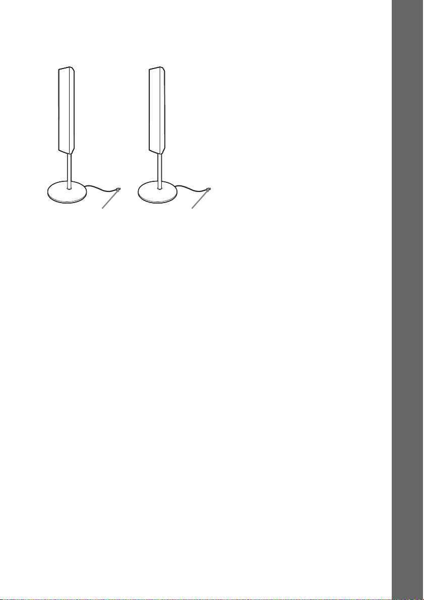
p
Step 1: Assembling the Speakers
d
Before connecting the speakers, attach the speaker stand to the speaker.
(For the front speakers.)
About how to connect the speaker cords to the SPEAKER jacks, see page 15.
Note
• Spread a cloth on the floor to avoid damaging the floor.
Ti
• You can use the speaker without the speaker stand by installing it on the wall (page 23).
Use the screws illustrated below.
Getting Started – BASIC –
Screw (small, black) Screw (small, silver) Screw (large, with
washer)
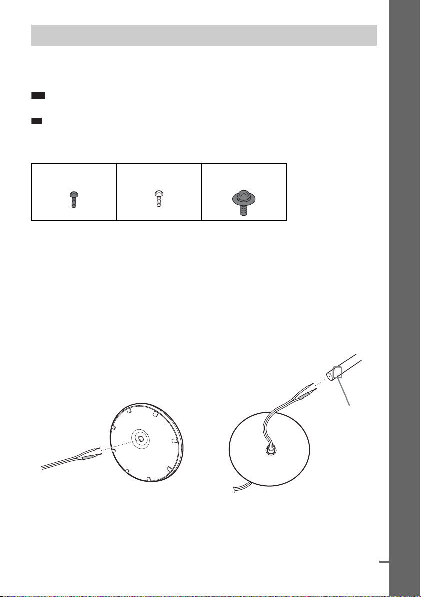
1 Thread the speaker cord through the hole on the base and post.
Be careful with the orientation of the post. Thread the speaker cord into the end of the post that has
2 holes.
About the speaker cord
The connector and color tube of the speaker cords are the same color as the label of the jacks to be
connected.
Use the speaker cords as follows:
• Front speaker (L): White
• Front speaker (R): Red
Post
Bottom of the base
,
2 holes
Speaker cord
Top of the base
continue
GB
9
2 Attach the post cover to the other end of the post.
Orient the slot toward you, attach the post cover so that the slot of the post engages with the tab of
the post cover, then secure with the screw.
Thread the speaker cord through
the hole of the post cover.
Speaker cord
Getting Started – BASIC –
Hole
Upper part of the
post
,
Post cover
,
Screw (small, black)
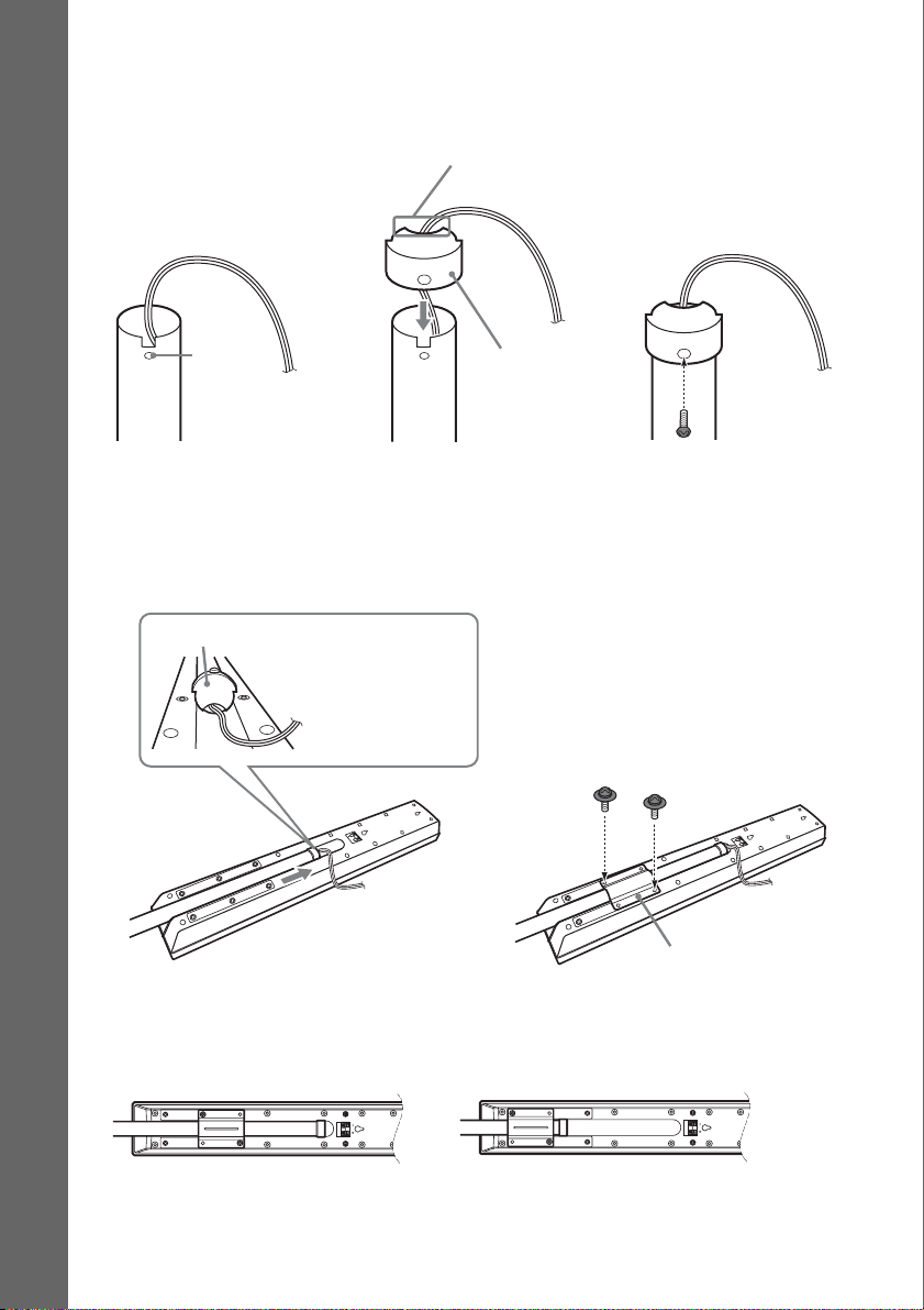
3 Lay the post in the slot of the speaker, slide the post to the end of the slot, then secure
the post with the mounting plate and screws.
Select the speaker whose color of the jack on the rear panel of speaker matches the color tube of
the speaker cord.
Post cover
Be careful the
orientation of the
post cover when
placing the post.
Secure 2 screws (large, with
washer) in criss-cross pattern.
,
Rear of the speaker
Mounting plate
When securing the mounting plate, position the mounting plate depending on the desired height of
the speaker.
Low position High position
After attaching the post to the base, you can adjust the height of the speaker.
GB
10
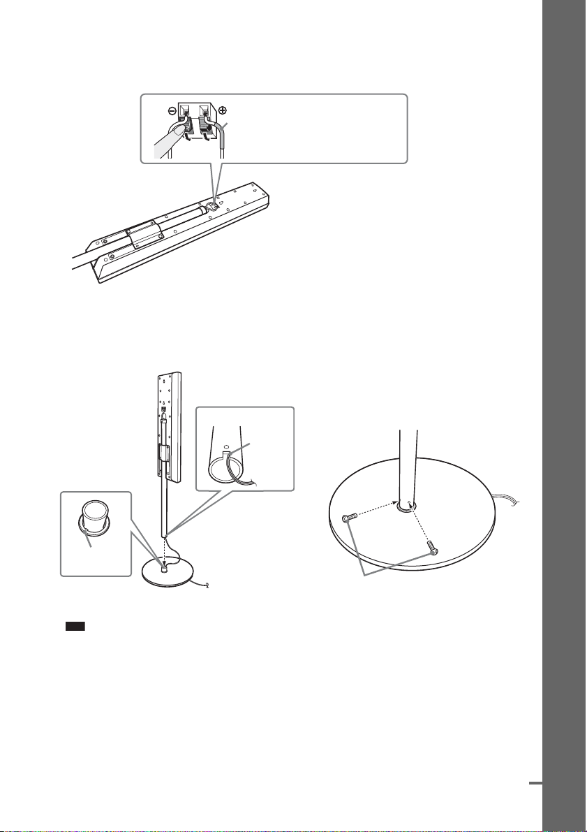
4 Connect the speaker cords to the speaker.
d
Be sure to match the speaker cord to the appropriate terminal on the components: 3 to 3, and #
to #.
Color tube
Front speaker (L): White
Front speaker (R): Red
Rear of the speaker
5 Attach the post to the base.
Insert the post so that the slit on the lower part of the post aligns with the projection of the base,
then secure the post with the 2 screws.
Post
Slit
Getting Started – BASIC –
,
Projection
Base
Screws
(small, silver)
Note
• Make sure that the slot on the post aligns with the projection of the base by rotating the post slightly.
continue
11
GB
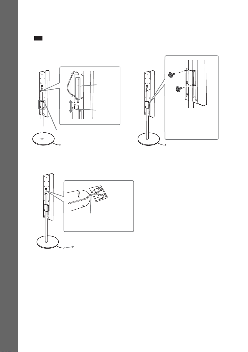
6 Adjust the height of the speaker.
Loosen (but do not remove) the screws, adjust the height of the speaker, then secure the screws.
Adjust the speaker of one side, then adjust another speaker by checking lines as a guide.
Note
• When adjusting the height of the speaker, grasp the speaker so that the speaker does not fall.
Getting Started – BASIC –
Lines
,
Post
Loosen 2 screws.
7 Take up any speaker cord slack.
Take up slack in the speaker cord by pulling from the bottom of the base.
Secure the speaker cord by
running it through the slot.
Adjust the length of the cord.
In addition to the screws
secured in Step 3, secure
2 more screws. (Secure 4
screws in total.)
12
GB
Fully-assembled illustration
Front speaker (L):
White label
White
Front speaker (R):
Red label
Red
Getting Started – BASIC –
13
GB
Step 2: Connecting the System and TV
The following is the basic connection of the unit to the speakers and TV. For other TV connections, see
page 24. For other component connection, see page 28.
To accept progressive signals, see page 26.
Refer to the connection diagram below, and read the additional information from 1 to 4 on the
following pages.
Getting Started – BASIC –
AC power cord (mains lead)
Front speaker (R)
SPEAKER
CENTER WOOFER
Subwoofer
FRONT R
SPEAKER
FRONT L SUR R SUR L
Center speaker
DIR-TC1
OUT
(DVD ONLY)
B
Front speaker (L)
DMPORT
TV /
VIDEO
(DVD ONLY)
YPB/CBPR/C
A
AUDIO
OUT
L
R
AM loop antenna (aerial)
COAXIAL
AM
RLAUDIO IN
VIDEO
S VIDEO
(DVD ONLY)
R
MONITOR OUTCOMPONENT VIDEO OUT
FM75
FM wire antenna
(aerial)
VIDEO
IN
TV
Surround speaker (R)
GB
14
Surround speaker (L)
:Signal flow
1 Connecting the Speakers
d
Required cords
The connector and color tube of the speaker cords are the same color as the label of the jacks to be
connected.
Getting Started – BASIC –
To the SPEAKER jack
Note
• Do not catch the speaker cord insulation in the SPEAKER jack.
Color tube
(+)
(–)
To avoid short-circuiting the speakers
Short-circuiting of the speakers may damage the system. To prevent this, be sure to follow these
precautions when connecting the speakers. Make sure the bare wire of each speaker cord does not touch
another speaker terminal or the bare wire of another speaker cord, such as shown below.
Stripped speaker cord is touching
another speaker terminal.
Stripped cords are touching each other
due to excessive removal of insulation.
After connecting all the components, speakers, and AC power cord (mains lead), output a test tone to
check that all the speakers are connected correctly. For details on outputting a test tone, see page 83.
If no sound is heard from a speaker while outputting a test tone, or a test tone is output from a speaker
other than the one currently displayed on the Setup Display, the speaker may be short-circuited. If this
happens, check the speaker connection again.
Note
• Be sure to match the speaker cord to the appropriate terminal on the components: 3 to 3, and # to #. If the cords
are reversed, the sound will lack bass and may be distorted.
continue
15
GB
2 Connecting the TV
p
p
Required cords
A Video cord
.
Yellow
B Audio cord (not supplied)
White (L/audio)
Red (R/audio)
Ti
Getting Started – BASIC –
• When you want to output the TV sound or stereo sound of a 2 channel source from the 6 speakers, select the “Dolby
Pro Logic,” “Dolby Pro Logic II MOVIE,” or “Dolby Pro Logic II MUSIC” sound field (page 34).
3 Connecting the Antenna (Aerial)
To connect the AM loop antenna (aerial)
The shape and the length of the antenna (aerial) is designed to receive AM signals. Do not dismantle
or roll up the antenna (aerial).
1 Remove only the loop part from the plastic stand.
2 Set up the AM loop antenna (aerial).
3 Connect the cords to the AM antenna (aerial) terminals.
Cord (A) or cord (B) can be connected to either terminal.
Insert the cord pushing
down the terminal clamp.
AB
Note
• Do not place the AM loop antenna (aerial) near the unit or other AV equipment, as noise may result.
Ti
• Adjust the direction of the AM loop antenna (aerial) for best AM broadcast sound.
Insert until this
part.
4 Make sure the AM loop antenna (aerial) is connected firmly by pulling softly.
GB
16
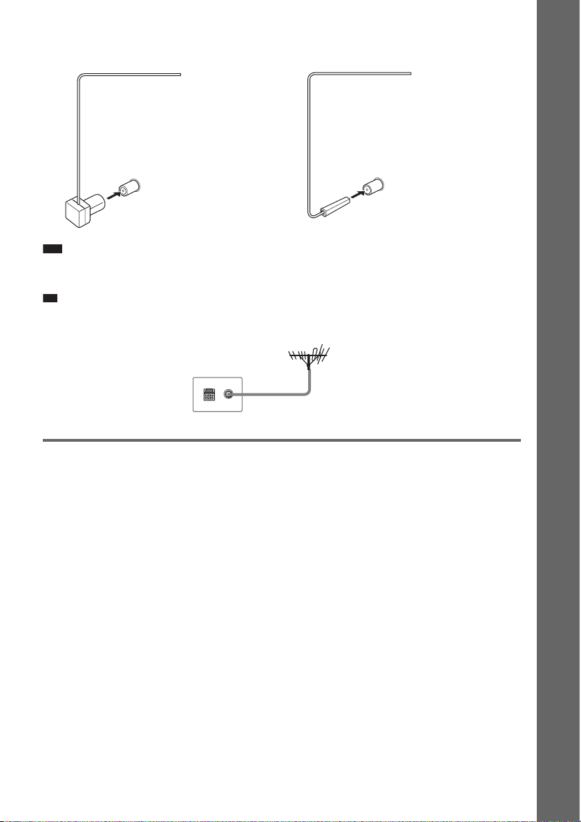
To connect the FM wire antenna (aerial)
p
Connect the FM wire antenna (aerial) to the COAXIAL FM 75 Ω jack.
FM wire antenna (aerial)
(supplied)
or
FM wire antenna (aerial)
(supplied)
Getting Started – BASIC –
COAXIAL FM 75 Ω jack
Note
COAXIAL FM 75 Ω jack
• Be sure to fully extend the FM wire antenna (aerial).
• After connecting the FM wire antenna (aerial), keep it as horizontal as possible.
Ti
• If you have poor FM reception, use a 75-ohm coaxial cable (not supplied) to connect the unit to an outdoor FM
antenna (aerial) as shown below.
Unit
Outdoor FM antenna (aerial)
4 Connecting the AC power cord (mains lead)
Before connecting the AC power cord (mains lead) of this unit to a wall outlet (mains), connect the
speakers to the unit.
GB
17
p
Step 3: Positioning the System
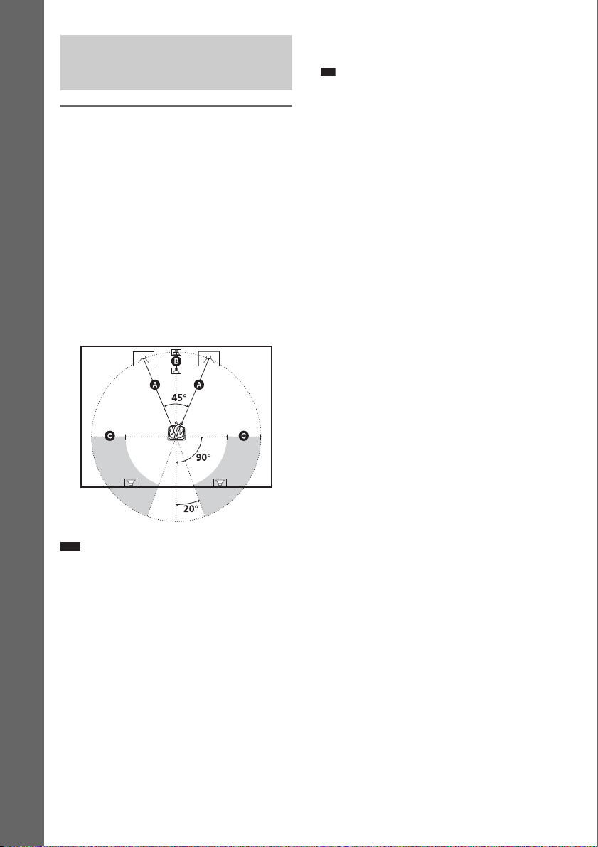
Positioning the speakers
For the best possible surround sound, all the
speakers other than the subwoofer should be
placed at the same distance from the listening
position (A).
However, this system allows you to place the
center speaker up to 1.6 meters (5 ft) closer (B)
Getting Started – BASIC –
and the surround speakers up to 5.0 meters (16
ft) closer (C) to the listening position.
The front speakers can be placed from 1.0 to
7.0 meters (3 to 23 ft) (A) from the listening
position.
Place speakers as illustrated below.
• Do not lean or hang on the speaker, as the speaker
may fall down.
Ti
• When you change the positions of the speakers, it is
recommended that you change the settings. For
details, see “Getting Optimal Surround Sound for a
Room” (page 72) and “Calibrating the Appropriate
Settings Automatically” (page 74).
Note
• Do not set the speakers in an inclined position.
• Do not place the speakers in locations that are:
– Extremely hot or cold
– Dusty or dirty
– Very humid
– Subject to vibrations
– Subject to direct sunlight
• Use caution when placing the speakers and/or
speaker stands that are attached with the speakers on
a specially treated (wax ed, oiled, polished, etc.) floor,
as staining or discoloration may result.
• When cleaning, use a soft cloth such as a cleaning
cloth for glasses.
• Do not use any type of abrasive pad, scouring
powder, or solvent such as alcohol or benzine.
GB
18
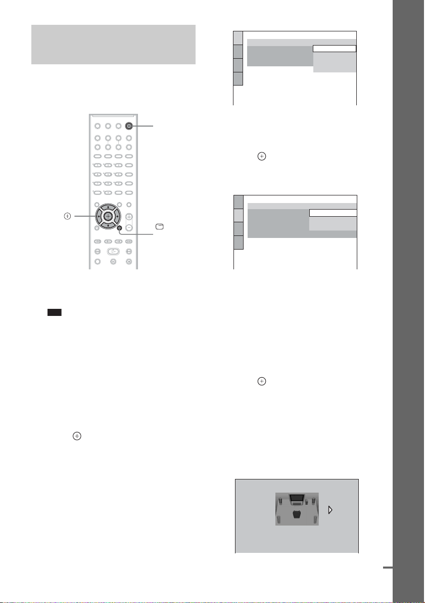
Step 4: Performing the
d
Quick Setup
Follow the steps below to make the minimum
number of basic adjustments for using the
system.
LANGUAGE SETUP
OSD:
MENU:
AUDIO:
SUBTITLE:
ENGLISH
ENGLISH
FRENCH
SPANISH
PORTUGUESE
Getting Started – BASIC –
"/1
C/X/x/c,
DISPLAY
1 Turn on the TV.
2 Press [/1.
Note
• Make sure that the function is set to “DVD”
(page 30).
3 Switch the input selector on your TV so
that the signal from the system
appears on the TV screen.
[Press [ENTER] to run QUICK SETUP.]
appears at the bottom of the TV screen. If
this message does not appear, recall the
Quick Setup display (page 21) and perform
again.
4 Press without inserting a disc.
The Setup Display for selecting the
language used in the on-screen display
appears.
5 Press X/x to select a language.
The system displays the menu and subtitles
in the selected language.
6 Press .
The Setup Display for selecting the aspect
ratio of the TV to be connected appears.
SCREEN SETUP
TV TYPE:
YC
BCR
/RGB (HDMI):
SCREEN SAVER:
BACKGROUND:
4:3 OUTPUT:
4:3 LETTER BOX
16:9
16:9
4:3 PAN SCAN
FULL
7 Press X/x to select the setting that
matches your TV type.
x If you have a wide-screen TV or a 4:3
standard TV with a wide-screen mode
[16:9] (page 78)
x If you have a 4:3 standard TV
[4:3 LETTER BOX] or [4:3 PAN SCAN]
(page 78)
8 Press .
The Setup Display for selecting the speaker
formation appears.
9 Press C/c to select the speaker
formation image as the speakers are
actually positioned.
For details, see “Getting Optimal Surround
Sound for a Room” (page 72).
SPEAKER FORMATION
STANDARD
continue
19
GB
Note
p
• When the wireless kit WAHT-SD1 (not
supplied) is installed, [STANDARD
(WIRELESS)] appears instead.
10 Press .
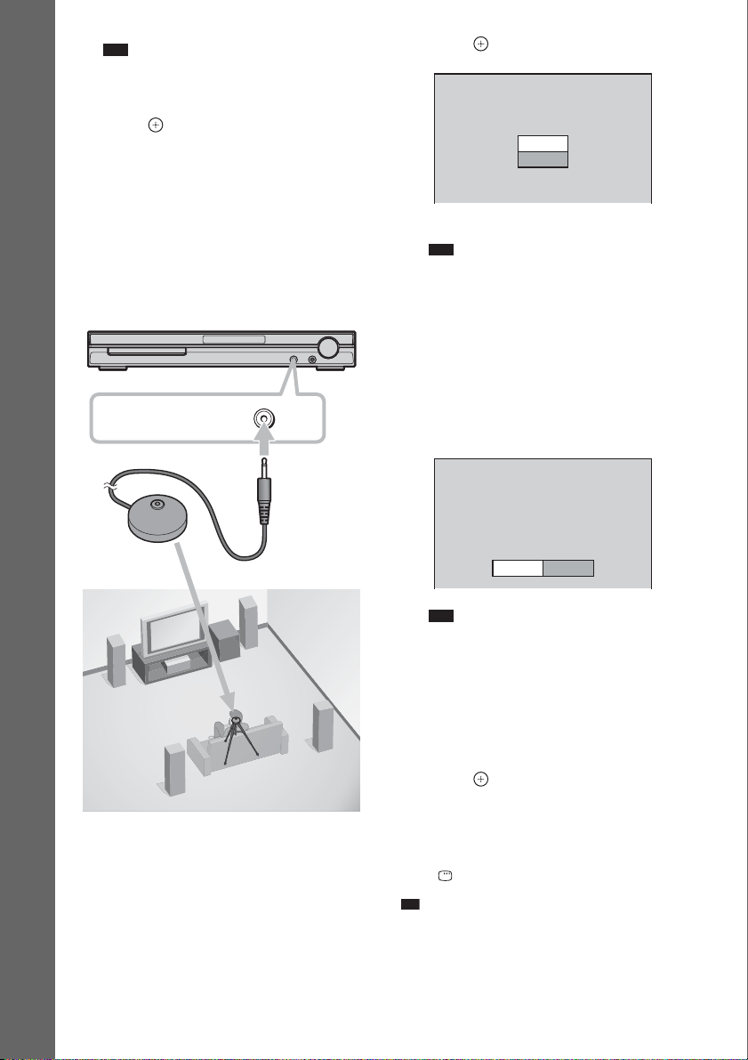
11 Connect the calibration mic to the
A.CAL MIC jack on the front panel and
press X/x to select [YES].
Set up the calibration mic at the ear level
using a tripod, etc. (not supplied). The front
of each speaker should face the calibration
Getting Started – BASIC –
mic, and there should be no obstruction
between the speakers and the calibration
mic. Be quiet during the measurement.
AUDIO IN / MIC 1 /
A.CAL MIC
Calibration mic
12 Press .
AUTO CALIBRATION
Connect calibration mic. Start
measurement?
YES
NO
Auto Calibration starts.
Note
• Loud test sound is output when [AUTO
CALIBRATION] starts. You cannot turn the
volume down. Give consideration to children
and neighbor.
• Avoid being in the measurement area and
making noise during the measurement (which
takes about 3 minutes), as it may interfere with
measurement.
13 Unplug the calibration mic and press C/
c to select [YES].
Measurement complete.
FRONT L :
FRONT R :
CENTER :
SUBWOOFER :
SURROUND L :
SURROUND R :
If OK, unplug calibration mic and select
“YES”.
YES
YES
YES
NONE
YES
NONE
NONE
NO
Note
• The environment of the room in which the
system is installed may affect measurements.
• If measurement fails, follow the message then
retry [AUTO CALIBRATION].
• When you select [SECOND ROOM] for
[SPEAKER FORMATION], measurement of
[SURROUND L] and [SURROUND R] is not
displayed.
14 Press .
Quick Setup is finished. All connections
and setup operations are complete.
To quit the Quick Setup
Press DISPLAY in any Step.
Ti
• If you change the position of the speakers, reset the
speaker settings. See “Getting Optimal Surround
Sound for a Room” (page 72) and “Calibrating the
Appropriate Settings Automatically” (page 74).
GB
20
• If you want to change any of the settings, see “Using
the Setup Display” (page 76).
To recall the Quick Setup display
1 Press DISPLAY when the system is in
stop mode.
The Control Menu display appears.
2 Press X/x to select [SETUP], then
press .
The options for [SETUP] appear.
)
1 2 ( 2 7
)
BNR
1 8 ( 3 4
T
QUICK
QUICK
CUSTOM
RESET
0 : 0 0 : 0 2
DVD VIDEO
3 Press X/x to select [QUICK], then press .
The Quick Setup display appears.
Getting Started – BASIC –
21
GB
Getting Started – ADVANCED –
Turning off the Demonstration
"/1
SYSTEM
MENU
X/x/c,
After connecting the AC power cord (mains
lead), the demonstration appears in the front
panel display. When you press "/1 on the
remote, the demonstration turns off.
Setting the demonstration mode to on/off
1 Press SYSTEM MENU.
2 Press X/x repeatedly until “DEMO”
appears in the front panel display, then
press or c.
3 Press X/x to select a setting.
The default setting is underlined.
• “DEMO ON”
mode to on.
• “DEMO OFF”: sets the demonstration
mode to off.
: sets the demonstration
4 Press .
The setting is made.
5 Press SYSTEM MENU.
The system menu turns off.
Note
• When you press "/1 on the unit, the demonstration
does not turn off.
• When you set the demonstration mode in the system
menu to on, the demonstration does not turn off even
though you press "/1 on the remote. To turn off the
demonstration, set the demonstration mode to off,
then press "/1 on the remote. When the
demonstration mode is set to off, the system saves
power in standby mode.
• If the system is at its factory default settings (ex. after
performing “COLD RESET” (page 84)), you can turn
off the demonstration simply by pressing "/1 on the
remote. Otherwise, to stop the demonstration, you
need to set “DEMO” to “DEMO OFF.”
GB
22
Installing the Speakers on
For the front speakers
a Wall
You can use the speakers by installing on the
wall.
Installing the speakers on a wall
1 Prepare screws (not supplied) that are
suitable for the hole on the back of
each speaker. See the illustrations
below.
5
4 mm (
/32 inch)
30 mm (1 3/16 inches)
4.6 mm
3
/16 inch)
(
10 mm
13
/32 inch)
(
Hole on the back of
the speaker
2 Fasten the screws to the wall.
For the center speaker
160 mm
5
/16 inches)
(6
100 mm
15
/16 inches)
(3
6 to 9 mm
1
(
/4 to 3/8
inch
)
For the other speakers
6 to 9 mm
1
/4 to 3/8
inch
(
)
3 Hang the speakers on the screws.
4.6 mm
3
/16 inch)
(
10 mm
13
/32 inch)
(
Getting Started – ADVANCED –
7 to 9 mm
9
/32 to 3/8
(
inch
Rear of speaker
)
Note
• Use screws that are suitable for the wall material and
strength. As a plaster board wall is especially fragile,
attach the screws securely to a beam and fasten them
to the wall. Install the speakers on a vertical and flat
wall where reinforcement is applied.
• Contact a screw shop or installer regarding the wall
material or screws to be used.
• Sony is not responsible for accident or damage
caused by improper installation, insufficient wall
strength or improper screw installation, natural
calamity, etc.
23
GB
Connecting the TV (Advanced)
Sends the played back DVD image to the connected TV.
Check the jacks of your TV, and choose connection method A, B, C, or D. Picture quality improves
in order from A (standard) to D (HDMI).
TV with HDMI* IN jack
D
IN
R
S VIDEO
(DVD ONLY)
VIDEO
MONITOR OUTCOMPONENT VIDEO OUT
To VIDEO
AM
To
S VIDEO
COAXIAL
FM75
SPEAKER
CENTER WOOFER
C
Y
PB/CB
PR/CR
TV with COMPONENT
VIDEO IN jacks
FRONT R
SPEAKER
FRONT L SUR R SUR L
B
S VIDEO
IN
To HDMI* OUT
DIR-TC1
OUT
(DVD ONLY)
To COMPONENT
VIDEO OUT
TV /
VIDEO
(DVD ONLY)
YPB/CBPR/C
A
TV with VIDEO IN jackTV with S VIDEO IN jack
DMPORT
RLAUDIO IN
VIDEO
IN
:Signal flow
* HDMI (high-definition multimedia interface)
The system incorporates High-Definition Multimedia Interface (HDMI
TM
) technology.
HDMI, the HDMI logo and High-Definition Multimedia Interface are trademarks or registered trademarks of
HDMI Licensing LLC.
24
GB
A To connect to a TV with the VIDEO IN jack
d
Connect the video cord.
.
Yellow
B To connect to a TV with the S VIDEO IN jack
Connect an S video cord (not supplied). To use the S video jack instead of the video jack, your TV
monitor must also be connected via an S video jack. S video signals are on a separate bus from the video
signals and will not be output through the video jack.
C To connect to a TV with the COMPONENT VIDEO IN jacks
Connect a component video cord (not supplied). To use the COMPONENT VIDEO OUT jacks (Y, PB/
C
B, PR/CR) instead of the video jack, your TV monitor must be equipped with via COMPONENT
VIDEO IN jacks (Y, P
B/CB, PR/CR). If your TV accepts progressive format signals, you must use this
connection and set the output channel of the system to progressive format (page 26).
Green
Blue
Red
D To connect to a TV with the HDMI (high-definition multimedia
interface)/DVI (digital visual interface) IN jack
Use a certified HDMI (high-definition multimedia interface) cord (not supplied) to enjoy high quality
digital picture and sound through the HDMI OUT (high-definition multimedia interface out) jack.
To connect to a TV with DVI (digital visual interface) input
Use an HDMI (high-definition multimedia interface)-DVI (digital visual interface) converter cord (not
supplied) with an HDMI (high-definition multimedia interface)-DVI (digital visual interface) adaptor
(not supplied). The DVI (digital visual interface) jack will not accept any audio signals. Furthermore,
you cannot connect the HDMI OUT (high-definition multimedia interface out) jack to DVI (digital
visual interface) jacks that are not HDCP (high-bandwidth digital content protection) compliant (e.g.,
DVI (digital visual interface) jacks on the computer displays).
To select the type of video signal output from the HDMI OUT (highdefinition multimedia interface out) jack
When you connect the unit and the TV with the HDMI cord, selects the type of video signals output
from the HDMI OUT (high-definition multimedia interface out) jack.
For details, refer also to the operating instructions supplied with the TV/projector, etc.
1 Press FUNCTION repeatedly to select “DVD.”
2 Press VIDEO FORMAT.
The current type of video signals appears in the front panel display.
Each time you press VIDEO FORMAT, the display changes as follows:
Getting Started – ADVANCED –
continue
25
GB
t 720 × 480p*
r
1280 × 720p*
r
720
× 480p*
r
× 1080i*
1920
• “720 × 480p*”: Sends 720 × 480p video signals.**
• “1280 × 720p*”: Sends 1280 × 720p video signals.
• “1920
× 1080i*”: Sends 1920 × 1080i video signals.
*i: interlace, p: progressive
**Depending on the country, [720 × 576p] may appear.
Note
• When the HDMI indicator on the front panel lights up, images other than [720 × 480p] or [720 × 576p] are stretched
vertically.
When connecting to a standard 4:3 screen TV
Depending on the disc, the image may not fit your TV screen.
To change the aspect ratio, see page 78.
Does your TV accept progressive signals?
Progressive is the method for displaying TV images which reduces flickering, and sharpens the image.
To display using this method, you need to connect to a TV that accepts progressive signals.
FUNCTION
VIDEO
FORMAT
“PROGRE” lights up in the front panel display when the system outputs progressive signals.
1 Press FUNCTION repeatedly to select “DVD.”
2 Press VIDEO FORMAT.
The current signal appears in the front panel display.
Each time you press VIDEO FORMAT, the display changes as follows:
GB
26

p
t NORMAL (INTERLACE)
r
PROGRESSIVE
x NORMAL (INTERLACE)
Select this setting when:
– your TV does not accept progressive signals, or,
– your TV is connected to jacks other than the COMPONENT VIDEO OUT jacks (MONITOR
OUT (VIDEO/S VIDEO)).
x PROGRESSIVE
Select this setting when:
– your TV accepts progressive signals, and,
– the TV is connected to the COMPONENT VIDEO OUT jacks.
Normally select this under the above condition. This automatically detects the software type, and
selects the appropriate conversion method.
Note that the picture will not be clear or no picture will appear if you select these settings when
either of the above conditions are not met.
Note
• When you connect the unit and the TV with the HDMI cord during the system is set to “NORMAL
(INTERLACE),” the system is set to “PROGRESSIVE” automatically.
Ti
• When you connect the unit and the TV with the HDMI cord, VIDEO FORMAT is used for selecting the type of
video signals output from the HDMI OUT jack. For details, see “To select the type of video signal output from the
HDMI OUT (high-definition multimedia interface out) jack” (page 25).
About DVD software types and the conversion method
DVD software can be divided into 2 types: film-based software and video-based software.
Video-based software is derived from TV, such as dramas and sit-coms, and displays images at 30
frames/60 fields per second. Film-based software is derived from film and displays images at 24 frames
per second. Some DVD software contains both video and film.
In order for these images to appear natural on your screen when output in progressive format, the
progressive signals need to be converted to match the type of DVD software that you are watching.
Note
• When you play video-based software in progressive signal format, sections of some types of images may appear
unnatural due to the conversion process when output through the COMPONENT VIDEO OUT jacks. Even though
you set to “PROGRESSIVE,” images from the MONITOR OUT (VIDEO or S VIDEO) jack are unaffected as they
are output in the interlace format.
Getting Started – ADVANCED –
GB
27
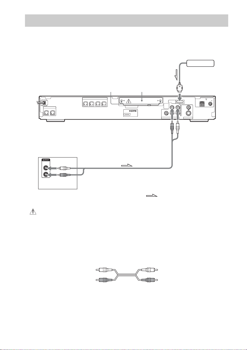
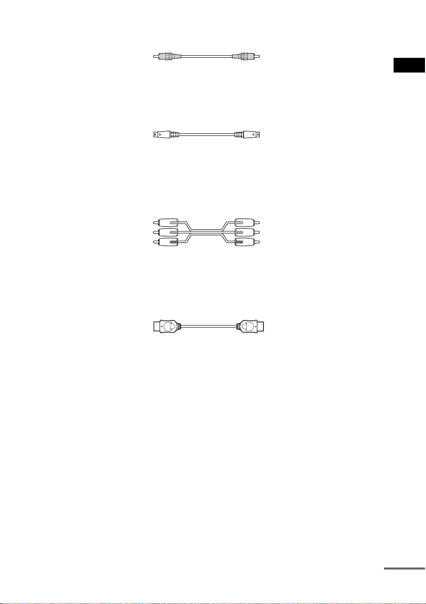
Connecting Other Components
You can enjoy sound using the speakers of this system by connecting the AUDIO OUT jacks of another
component. For video connection of other components, connect directly to the TV.
DIGITAL MEDIA
PORT adapter
SPEAKER
CENTER WOOFER
FRONT R
SPEAKER
FRONT L SUR R SUR L
Screws*
DIR-TC1 slot for
the WAHT-SD1
DIR-TC1
OUT
(DVD ONLY)
VIDEO
(DVD ONLY)
TV /
YPB/CBPR/C
DMPORT
RLAUDIO IN
R
To DMPORT jack
AM
VIDEO
S VIDEO
(DVD ONLY)
MONITOR OUTCOMPONENT VIDEO OUT
COAXIAL
FM75
To TV/VIDEO
(AUDIO IN)
AUDIO
OUT
L
R
VCR, digital satellite receiver
or PlayStation, etc.
:Signal flow
* CAUTION
Please do not remove the screws before installing the WAHT-SD1.
To connect the AUDIO OUT jacks of other components to the TV/VIDEO
(AUDIO IN) jacks of this unit
Connect the VCR or other components to the TV/VIDEO (AUDIO IN) jacks using the audio cord (not
supplied). When connecting a cord, be sure to match the color-coded sleeves to the appropriate jacks
on the components.
White (L/audio)
Red (R/audio)
To connect the DIGITAL MEDIA PORT adapter
Connect a DIGITAL MEDIA PORT adapter (not supplied) to the DMPORT jack. For details of the
DIGITAL MEDIA PORT adapter, see “Using the DIGITAL MEDIA PORT Adapter” (page 67).
GB
28

To listen to the portable audio source sound through the system
p
Connect the audio output jacks of the portable audio source to the AUDIO IN jack on the front panel
of the unit with the stereo mini-plug cord (not supplied).
Ti
• When listening to MP3 format recordings using a portable audio source, you can enhance the sound.
Press FUNCTION to select “AUDIO.” Connect the portable audio source. Press SOUND FIELD repeatedly until
“A.F.D. STD” appears in the front panel display.
To cancel, select other than “A.F.D. STD.”
Wireless system option
When you install the WAHT-SD1 (not supplied) in the DIR-TC1 slot, you can enjoy wireless
performance by transmission of the sound to the surround speakers. For details, see the operating
instructions of the WAHT-SD1.
Note
• Be sure to make connections securely to avoid hum and noise.
• When you connect another component with a volume control, turn up the volume of the other components to a level
where sound is not distorted.
Getting Started – ADVANCED –
GB
29
p
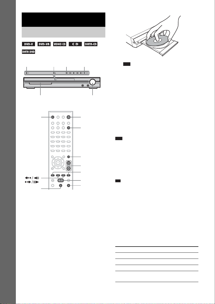
Basic Operations
Playing Discs
"/1
A
H
FUNCTION
Basic Operations
Disc tray
Z
/
X
Depending on the DVD VIDEO or VIDEO CD,
some operations may be different or restricted.
Refer to the operating instructions supplied with
your disc.
1 Turn on your TV.
2 Switch the input selector on the TV to
this system.
3 Press "/1.
The system turns on.
Unless the system is set to “DVD,” press
FUNCTION to select “DVD.”
4 Press A.
5 Load a disc.
Place one disc on the tray, and then press A.
Adjust the
volume
"/1
FUNCTION
MUTING
VOLUME +/–
./>
H
x
Note
• When you play an 8 cm disc, place it on the
inner circle of the tray. Be careful that th e disc is
not skewed on the inner circle of the tray.
• Do not forcibly press the disc tray closed with
your finger, as this may cause malfunction.
• Do not place more than one disc on the tray.
6 Press H.
The system starts playback (continuous
play).
Adjust the volume on the unit.
The volume level appears on the TV screen
and in the front panel display.
Note
• Depending on the system status, the volume level
may not appear on the TV screen.
• When you set the HDMI CONTROL function to on
(page 80), the TV that is connected to the system with
the HDMI cord can be synch-operated with the
system. For details, see the HDMI CONTROL Guide
(supplied separately).
Ti
• When you connect the system and TV with the HDMI
cord, you can operate them simply, using the HDMI
CONTROL function. For details, see the HDMI
CONTROL Guide (supplied separately).
To save the power in standby
mode
Press "/1 while the system turns on. To cancel
standby mode, press "/1 once.
Additional operations
To Press
Stop x
Pause X
Resume play after pause X or H
Go to the next chapter,
track, or scene
> (except for JPEG)
GB
30
 Loading...