

Sony DAV-DZ361W Operating Instructions
3-879-443-11(1)
DVD Home Theatre
System
Operating Instructions
DAV-DZ361W
©2008 Sony Corporation
WARNING
To reduce the risk of fire or electric
shock, do not expose this apparatus to
rain or moisture.
Do not install the appliance in a confined space, such
as a bookcase or built-in cabinet.
To prevent fire, do not cover the ventilation of the
apparatus with news papers, table-cloths, curtains, etc.
And don’t place lighted candles on the apparatus.
To prevent fire or shock hazard, do not place objects
filled with liquids, such as vases, on the apparatus.
Batteries or batteries installed apparatus shall not be
exposed to excessive heat such as sunshine, fire or the
like.
In door use only.
This appliance is
classified as a CLASS 1
LASER product. This
marking is loca ted on the
rear exterior.
NOTICE FOR THE CUSTOMERS IN THE
UNITED KINGDOM
A moulded plug complying with BS1363 is fitted to
this equipment for your safety and convenience.
Should the fuse in the plug supplied need to be
replaced, a fuse of the same rating as the supplied one
and approved by ASTA or BSI to BS1362, (i.e.,
marked with mark or mark) must be used.
If the plug supplied with this equipment has a
detachable fuse cover, be sure to attach the fuse cover
after you change the fuse. Never use the plug without
the fuse cover.
If you should lose the fuse cover, please contact your
nearest Sony service station.
Disposal of Old
Electrical & Electronic
Equipment (Applicable
in the European Union
and other European
countries with separate
collection systems)
This symbol on the product or
on its packaging indicates that
this product shall not be treated as household waste.
Instead it shall be handed over to the applicable
collection point for the recycling of electrical and
electronic equipment. By ensuring this product is
disposed of correctly, you will help prevent potential
negative consequence s for the environment and human
health, which could otherwise be caused by
inappropriate waste handling of this product. The
recycling of materials will help to conserve natural
resources. For more detailed information about
recycling of this product, please contact your local
Civic Office, your household waste disposal service or
the shop where you purchased the product.
Disposal of waste
batteries (applicable in
the European Union and
other European
countries with separate
collection systems)
This symbol on the battery or on the packaging
indicates that the battery provided with this product
shall not be treated as household waste. By ensuring
these batteries are disposed of correctly, you will help
prevent potentially negative consequences for the
environment and human health which could otherwise
be caused by inappropriate waste handling of the
battery. The recycling of the materials will help to
conserve natural resources. In case of products that for
safety, performance or data integrity reasons require a
permanent connection with an incorporated battery,
this battery should be replaced by qualified service
staff only. To ensure that the battery will be treated
properly, hand over the product at end-of-life to the
applicable collection point for the recycling of
electrical and electronic equipment. For all other
batteries, please view the section on how to remove the
battery from the product safely. Hand the battery over
to the applicable collection point for the recycling of
waste batteries. For more detailed information about
recycling of this product or battery, please contact your
local Civic Office, your household waste disposal
service or the shop where you purchased the product.
The manufacturer of this product is Sony Corporation,
1-7-1 Konan Minato-ku Tokyo, 108-0075 Japan. The
Authorized Representative for EMC and product
safety is Sony Deutschland GmbH, Hedelfinger
Strasse 61, 70327 Stuttgart, Germany. For any service
or guarantee matters please refer to the addresses given
in separate service or guarantee documents.
GB
2

Precautions
On power sources
• AC power cord (mains lead) must be changed only at
the qualified service shop.
• The unit is not disconnected from the AC power
source (mains) as long as it is connected to the wall
outlet (mains), even if the unit itself has been turned
off.
• Install this system so that the AC power cord (mains
lead) can be unplugged from the wall socket
immediately in the event of trouble.
About This Operating Instructions
• The instructions in this Operating Instructions
describe the controls on the remote. You can
also use the controls on the unit if they have the
same or similar names as those on the remote.
• The Control Menu items may vary depending
on the area.
• “DVD” may be used as a general term for a
DVD VIDEO, DVD+RW/DVD+R, and DVDRW/DVD-R.
• Measurements are expressed in feet (ft) for
North American models.
• The default setting is underlined.
About the S-AIR function
The system is compatible with the S-AIR
function, which allows transmission of sound
between S-AIR products wirelessly.
The following S-AIR products can be used with
the system:
• Surround amplifier (supplied): You can enjoy
surround speaker sound wirelessly.
• S-AIR receiver (optional): You can enjoy
system sound in another room.
The S-AIR receiver can be purchased as an
option (the S-AIR product lineup differs
depending on the area).
Notes or instructions for the surround amplifier
or S-AIR receiver in this operating instructions
refer only to when the surround amplifier or
S-AIR receiver is used.
For details on the S-AIR function, see “Using an
S-AIR Product” (page 73).
GB
3

Table of Contents
About This Operating Instructions..........3
About the S-AIR function .......................3
Playable Discs......................................... 5
Getting Started
Step 1: Positioning the System ...10
Step 2: Connecting the System ...13
Step 3: Setting up the Wireless
System .....................................21
Step 4: Performing the Quick
Setup ........................................23
Step 5: Enjoying Sound from all the
Speakers ..................................26
Sound Adjustment
Enjoying Surround Sound by Using
Decoding Mode ..............................28
Selecting the Sound Mode....................30
Enjoying Multiplex Broadcast Sound... 30
Disc
Playing a Disc ....................................... 31
Using Play Mode...................................36
Searching/Selecting a Disc ...................39
Playing MP3 Files/JPEG Image Files... 41
Enjoying DivX® Videos.......................44
Adjusting the Delay Between the Picture
and Sound ....................................... 46
Restricting Playback of the Disc...........47
Using the Setup Display........................49
Tuner
Presetting Radio Stations ...................... 56
Listening to the Radio...........................57
Using the Radio Data System (RDS).... 59
Control for HDMI/External
Audio Device
Using the Control for HDMI Function for
“BRAVIA” Sync ............................ 60
Playing Back Audio Files/JPEG Image
Files of a USB Device .................... 63
Storing Songs in a USB Device ............ 69
Using the DIGITAL MEDIA PORT
Adapter ........................................... 72
Using an S-AIR Product ....................... 73
Other Operations
Getting Optimal Surround Sound for a
Room .............................................. 79
Calibrating the Appropriate Settings
Automatically................................. 80
Controlling the TV with the Supplied
Remote ........................................... 81
Using the Sound Effect......................... 82
Using the Sleep Timer .......................... 82
Changing the Brightness of the Front
Panel Display.................................. 83
Viewing Information About the Disc... 83
Returning to the Default Settings ......... 86
Additional Information
Precautions ........................................... 87
Notes about the Discs ........................... 88
Troubleshooting.................................... 89
Self-diagnosis Function ........................ 99
Specifications ..................................... 100
Glossary.............................................. 102
Language Code List............................ 104
Index to Parts and Control .................. 105
Guide to the Control Menu Display ... 110
Index ................................................... 114
GB
4
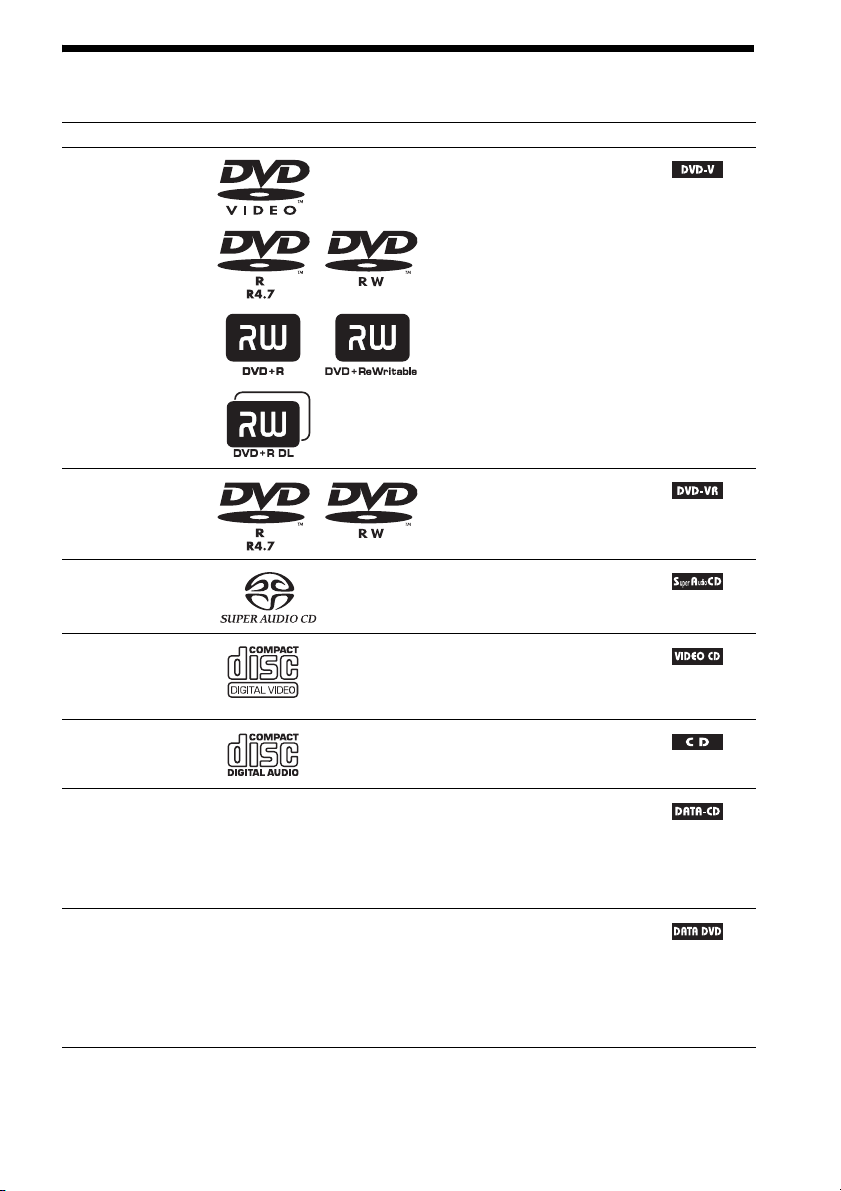
Playable Discs
Type Disc logo Characteristics Icon
DVD VIDEO • DVD VIDEO
• DVD-R/DVD-RW in DVD
VIDEO format or video mode
• DVD+R/DVD+RW in DVD
VIDEO format
VR (Video
Recording) mode
• DVD-R/DVD-RW in VR (Video
Recording) mode (except for
DVD-R DL)
Super Audio CD • Super Audio CD
VIDEO CD • VIDEO CD (Ver. 1.1 and 2.0 discs)
• Super VCD
• CD-R/CD-RW/CD-ROM in video
CD format or Super VCD format
CD • Audio CD
• CD-R/CD-RW in audio CD format
DATA CD – • CD-R/CD-RW/CD-ROM in
DATA CD format, containing MP3
files1), JPEG image files2), and
DivX video files
conforming to ISO 9660
3)4)
, and
5)
Level 1/
Level 2, or Joliet (extended format)
DATA DVD – • DVD-ROM/DVD-R/DVD-RW/
DVD+R/DVD+RW in DATA
DVD format, containing MP3
files1), JPEG image files2), and
DivX video files
3)4)
, and
conforming to UDF (Universal
Disk Format)
1)
MP3 (MPEG1 Audio Layer 3) is a standard format defined by ISO/MPEG which compresses audio data. MP3 files
must be in MPEG1 Audio Layer 3 format.
GB
5

2)
JPEG image files must conform to the DCF image file format. (DCF “Design rule for Camera File system”: Image
standards for digital cameras regulated by Japan Electronics and Information Technology Industries Association
(JEITA).)
3)
DivX® is a video file compression technology, developed by DivX, Inc.
4)
DivX, DivX Certified, and associated logos are trademarks of DivX, Inc. and are used under license.
5)
A logical format of files and folders on CD-ROMs, defined by ISO (International Organization for
Standardization).
“DVD-RW,” “DVD+RW,” “DVD+R,”“DVD VIDEO,” and the “CD” logos are trademarks.
Example of discs that the system cannot play
The system cannot play the following discs:
• CD-ROM/CD-R/CD-RW other than those recorded in the formats listed on page 5
• CD-ROM recorded in PHOTO CD format
• Data part of CD-Extra
• CD Graphics disc
• DVD Audio
• DATA DVD that does not contain MP3 files, JPEG image files, or DivX video files
•DVD-RAM
Also, the system cannot play the following discs:
• A DVD VIDEO with a different region code (page 7)
• A disc that has a non-standard shape (e.g., card, heart)
• A disc with paper or stickers on it
• A disc that has the adhesive of cellophane tape or a sticker still left on it
Note about CD-R/CD-RW/DVD-R/DVD-RW/DVD+R/DVD+RW
In some cases, CD-R/CD-RW/DVD-R/DVD-RW/DVD+R/DVD+RW cannot be played on this system
due to the recording quality or physical condition of the disc, or the characteristics of the recording
device and authoring software.
The disc will not play if it has not been correctly finalized. For more information, refer to the operating
instructions for the recording device.
Note that some playback functions may not work with some DVD+RWs/DVD+Rs, even if they have
been correctly finalized. In this case, view the disc by normal playback. Also some DATA CDs/DATA
DVDs created in Packet Write format cannot be played.
Music discs encoded with copyright protection technologies
This product is designed to play back discs that conform to the Compact Disc (CD) standard.
Recently, various music discs encoded with copyright protection technologies are marketed by some
record companies. Please be aware that among those discs, there are some that do not conform to the
CD standard and may not be playable by this product.
Note on DualDiscs
A DualDisc is a two sided disc product which mates DVD recorded material on one side with digital
audio material on the other side. However, since the audio material side does not conform to the
Compact Disc (CD) standard, playback on this product is not guaranteed.
GB
6
About Multi Session CD
• This system can play a Multi Session CD when an MP3 file is contained in the first session. Any
subsequent MP3 files recorded in later sessions can also be played back.
• This system can play a Multi Session CD when a JPEG image file is contained in the first session.
Any subsequent JPEG image files recorded in later sessions can also be played back.
• If MP3 files and JPEG image files in music CD format or video CD format are recorded in the first
session, only the first session will be played back.
Region code
Your system has a region code printed on the rear of the unit and will only play a DVD labeled with
the same region code.
A DVD VIDEO labeled will also play on this system.
If you try to play any other DVD VIDEO, the message [Playback prohibited by area limitations.] will
appear on the TV screen. Depending on the DVD VIDEO, no region code indication may be given even
though playing the DVD VIDEO is prohibited by area restrictions.
ALL
Note about playback operations of a DVD or VIDEO CD
Some playback operations on a DVD or VIDEO CD may be intentionally set by software producers.
Since this system will play a DVD or VIDEO CD according to the disc contents the software producers
designed, some playback features may not be available. Be sure to read the operating instructions
supplied with the DVD or VIDEO CD.
Copyrights
This product incorporates copyright protection technology that is protected by U.S. patents and other
intellectual property rights. Use of this copyright protection technology must be authorized by
Macrovision, and is intended for home and other limited viewing uses only unless otherwise authorized
by Macrovision. Reverse engineering or disassembly is prohibited.
This system incorporates with Dolby* Digital and Dolby Pro Logic (II) adaptive matrix surround
decoder and the DTS** Digital Surround System.
* Manufactured under license from Dolby Laboratories.
“Dolby”, “Pro Logic”, and the double-D symbol are trademarks of Dolby Laboratories.
** Manufactured under license from DTS, Inc.
“DTS” and “DTS Digital Surround” are registered trademarks of DTS, Inc.
This system incorporates High-Definition Multimedia Interface (HDMITM) technology.
HDMI, the HDMI logo and High-Definition Multimedia Interface are trademarks or registered
trademarks of HDMI Licensing LLC.
“BRAVIA” and are trademarks of Sony Corporation.
“S-AIR” and its logo are trademarks of Sony Corporation.
GB
7
Getting Started
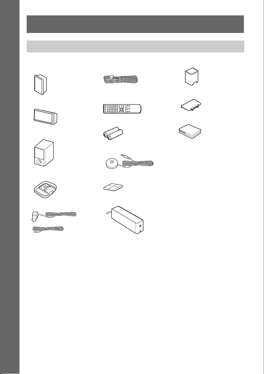
Unpacking
• Front speakers (2) and
surround speakers (2)
Getting Started
• Center speaker (1)
• Subwoofer (1)
• AM loop antenna (aerial) (1)
• FM wire antenna (aerial) (1)
or
• Speaker cords (6, red/white/
green/gray/blue/purple)
• Remote commander
(remote) (1)
• R6 (size AA) batteries (2)
• Calibration mic (1)
• Foot pads (1 set)
• Surround amplifier (1)
• Speaker cord cover (1)
• Speaker cord holder (1)
• Wireless transceivers (2)
• Operating Instructions
• Speaker and T V connections
(card)
GB
8
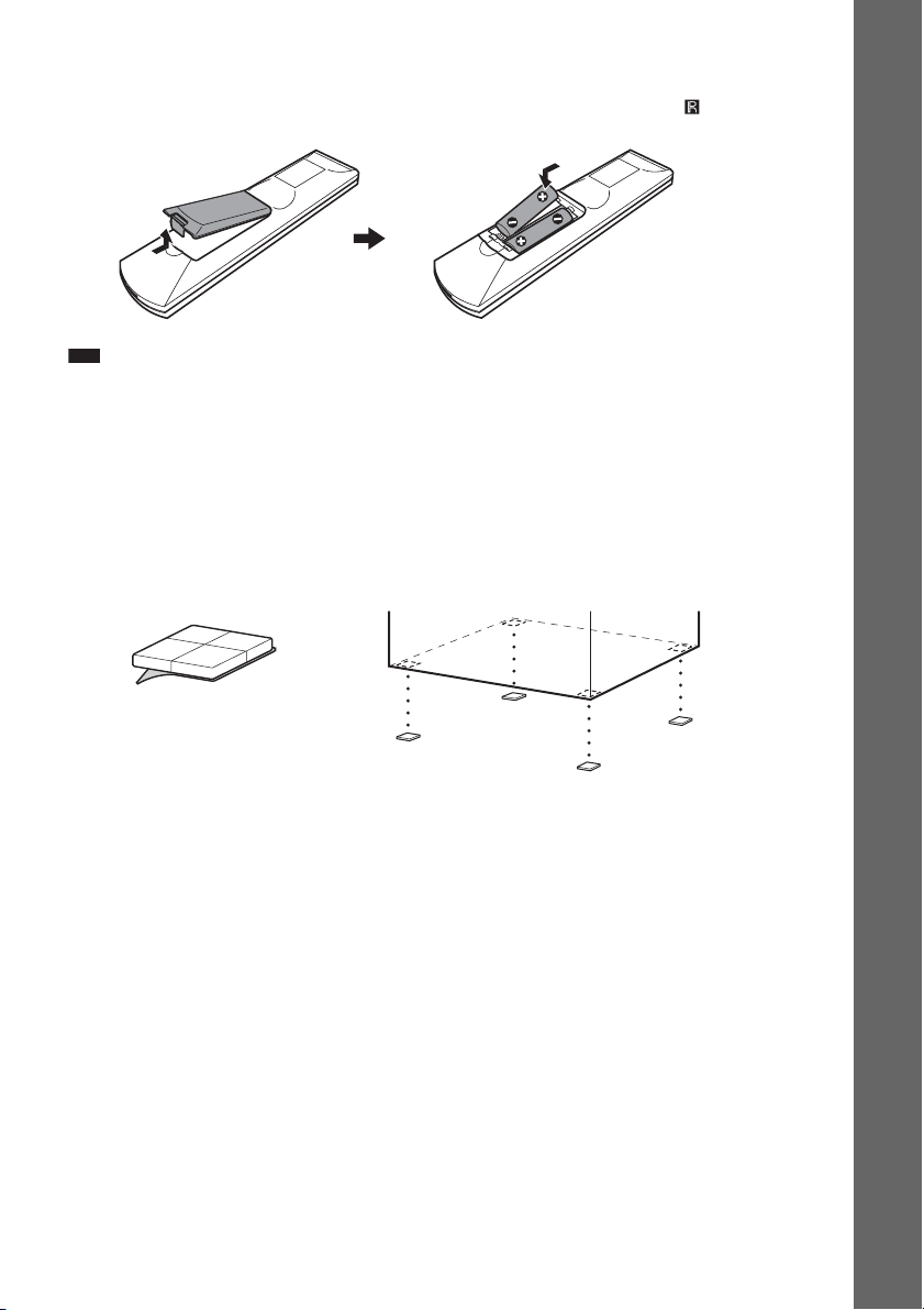
Inserting batteries into the remote
Insert two R6 (size AA) batteries (supplied) by matching the 3 and # ends on the batteries to the
markings inside the compartment. To use the remote, point it at the remote sensor on the unit.
Note
• Do not leave the remote in an extremely hot or humid place.
• Do not use a new battery with an old one.
• Do not drop any foreign object into the remote casing, particularly when replacing the batteries.
• Do not expose the remote sensor to direct sunlight or lighting apparatus. Doing so may cause a malfunction.
• If you do not intend to use the remote for an extended period of time, remove the batteries to avoid possible damage
from battery leakage and corrosion.
Attaching the foot pads to the subwoofer
Attach the foot pads (supplied) to the bottom of the subwoofer to stabilize the subwoofer and prevent
it from slipping.
,
Getting Started
Remove the foot pads from
the mount seat.
GB
9
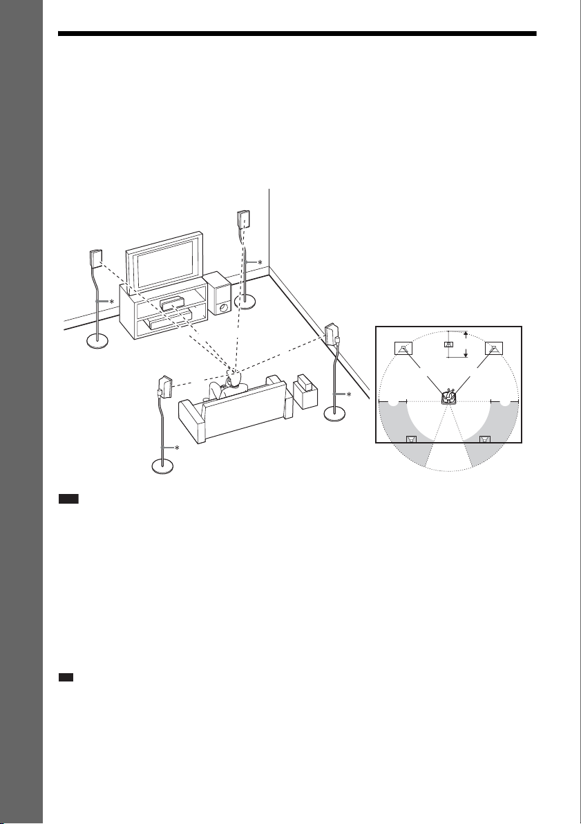
Step 1: Positioning the System
p
For the best possible surround sound, all the speakers other than the subwoofer should be placed at the
same distance from the listening position (A).
However, this system allows you to place the center speaker up to 1.6 meters (5 ft) closer (B) and the
surround speakers up to 5.0 meters (16 ft) closer (C) to the front speakers.
The front speakers can be placed from 1.0 to 7.0 meters (3 to 23 ft) (A) from the listening position.
Getting Started
Place the system as illustrated below.
A Front speaker (L (left))
B Front speaker (R (right))
C Center speaker
D Surround speaker (L (left))
E Surround speaker (R (right))
F Subwoofer
G Unit
H Surround amplifier
E
Top view
A
C C
C
B
AA
A
D
A
C
G
A
A
B
F
A
A
H
B
D
* Not supplied.
Note
• Do not set the speakers in an inclined position.
• Do not place the speakers in locations that are:
– Extremely hot or cold
– Dusty or dirty
– Very humid
– Subject to vibrations
– Subject to direct sunlight
• Use caution when placing the speakers and/or speaker stands attached to the speakers on a specially treated (waxed,
oiled, polished, etc.) floor, as staining or discoloration may result.
• Do not use any type of abrasive pad, scouring powder, or solvent such as alcohol or benzine.
• Do not lean or hang on the speaker, as the speaker may fall down.
Ti
• When you change the positions of the speakers, Sony recommends that you change the settings. For details, see
“Getting Optimal Surround Sound f or a Room” (page 79) and “Cal ibrating the Appropriate Settings Automatically ”
(page 80).
GB
10
E
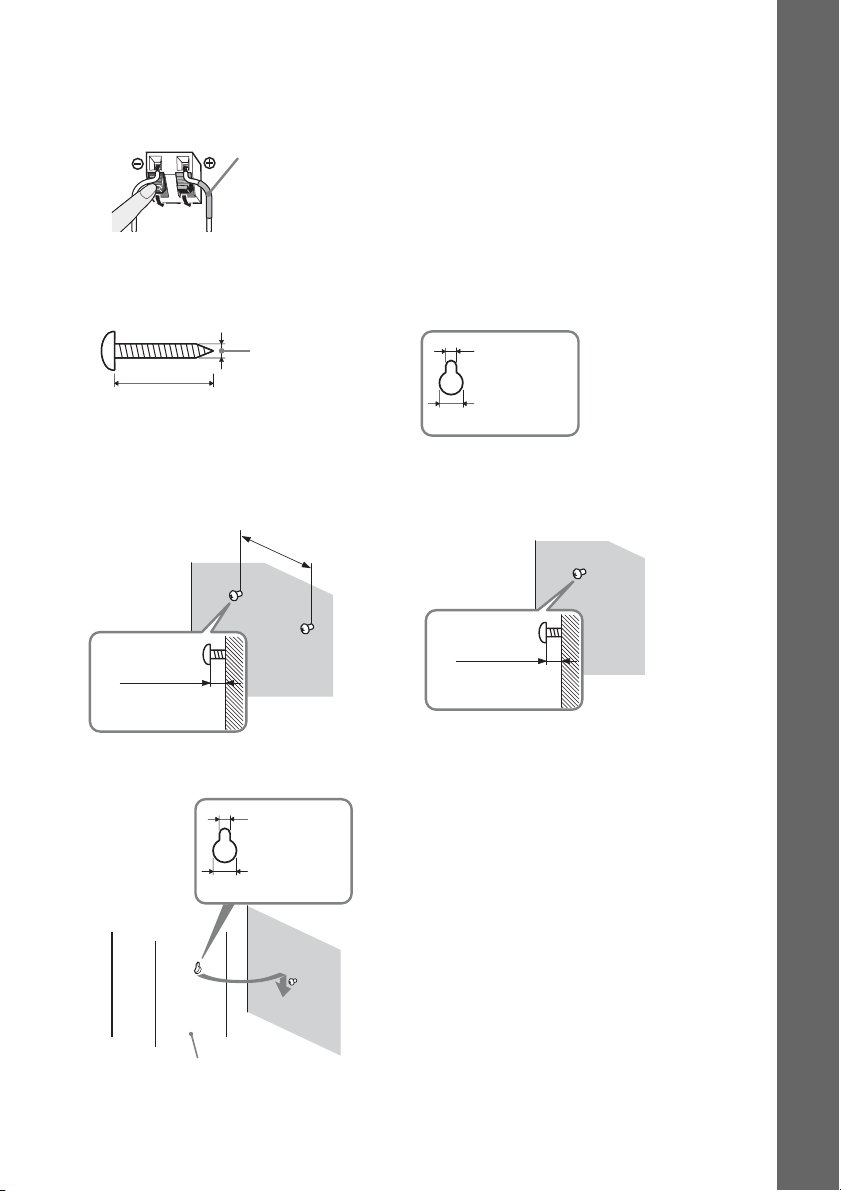
To install the speakers on a wall
Before installing the speakers on a wall, connect the speaker cord to the speaker.
Be sure to match the speaker cords to the appropriate terminals on the speakers: the speaker cord with
the color tube to 3, and the speaker cord without the color tube to #.
Color tube
Front speaker (L): White
Front speaker (R): Red
Center speaker: Green
Surround speaker (L): Blue
Surround speaker (R): Gray
1 Prepare screws (not supplied) that are suitable for the hole on the back of each speaker.
See the illustrations below.
Getting Started
5
4 mm (
/32 inch)
30 mm (1 3/16 inches)
2 Fasten the screws to the wall.
For the center speaker
145 mm
3
/4 inches)
(5
8 to 10 mm
11
/32 to 13/32
(
inch
)
3 Hang the speakers on the screws.
5 mm
7
/32 inch)
(
10 mm
13
/32 inch)
(
For the other speakers
11
(
/32 to 13/32
Hole on the back of
the speaker
5 mm
7
/32 inch)
(
10 mm
13
(
/32 inch)
8 to 10 mm
inch
)
Hole on the back of
the speaker
Rear of the speaker
11
GB

Note
• Use screws that are suitable for the wall material and strength. As a plaster board wall is especially fragile, attach
the screws securely to a beam and fasten them to the wall. Install the speakers on a vertical and flat wall where
reinforcement is applied.
• Contact a screw shop or installer regarding the wall material or screws to be used.
• Sony is not responsible for accident or damage caused by improper installation, insufficient wall strength or
improper screw installation, natural calamity, etc.
Getting Started
12
GB
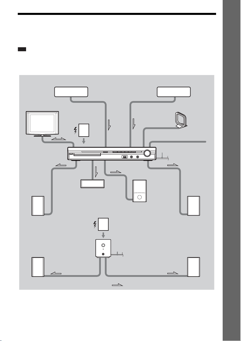
Step 2: Connecting the System
See the connection diagram below, and read the additional information from 1 to 6 on the following
pages.
Note
• Be sure to make connections securely to avoid hum and noise.
• When you connect another component with a volume control, turn up the volume of the other components to a level
where sound is not distorted.
Getting Started
2 TV
1 Front speaker (L)
3 DIGITAL MEDIA
PORT adapter
5 Wireless
transceiver
1 Center speaker
Surround
amplifier
1 Subwoofer
5 Wireless
transceiver
6 AC power cord
(mains lead)
3 Portable audio source
4 AM loop antenna (aerial)
4 FM wire antenna (aerial)
6 AC power cord (mains lead)
1 Front speaker (R)
1 Surround speaker (L)
:Signal flow
1 Surround speaker (R)
13
GB
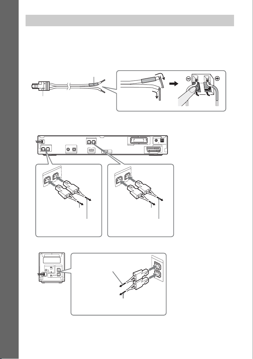
1 Connecting the Speakers
The connector and color tube of the speaker cords are the same color as the label of the jacks to be
connected. Be sure to match the speaker cords to the appropriate terminals on the speakers: the speaker
cord with the color tube to 3, and the speaker cord without the color tube to #. Do not catch the
speaker cord insulation in the speaker terminals.
Getting Started
Color tube
Rear of speaker
(+)
Connector
(–)
When connecting to the unit, insert the connector until it clicks.
Rear panel of the unit
SPEAKER
SPEAKER
CENTER SUBWOOFER
SPEAKER
CENTER
DIGITAL IN
COAXIAL OPTICAL
SUBWOOFER
FRONT R FRONT L
TV HDMI OUT
To the center speaker
(green)
To the subwoofer
(purple)
Rear panel of the surround amplifier
EZW-RT
10
S-AIR ID
SPEAKER
A
PAIRIN G
SURROUND SELECTOR
B
C
SURROUND
SURROUND
BACK
To the surround speaker (L)
L
(blue)
R
DC5V
0.7A MAX
DMPORT
To the front speaker (R)
(red)
EZW-RT10
OUTPUT(TO TV)
SPEAKER
FRONT L
FRONT R
To the front speaker (L)
(white)
ANTENNA
COAXIAL 75
AM
FM
EURO AV
S
P
E
A
K
E
R
L
R
14
To the surround speaker (R) (gray)
GB
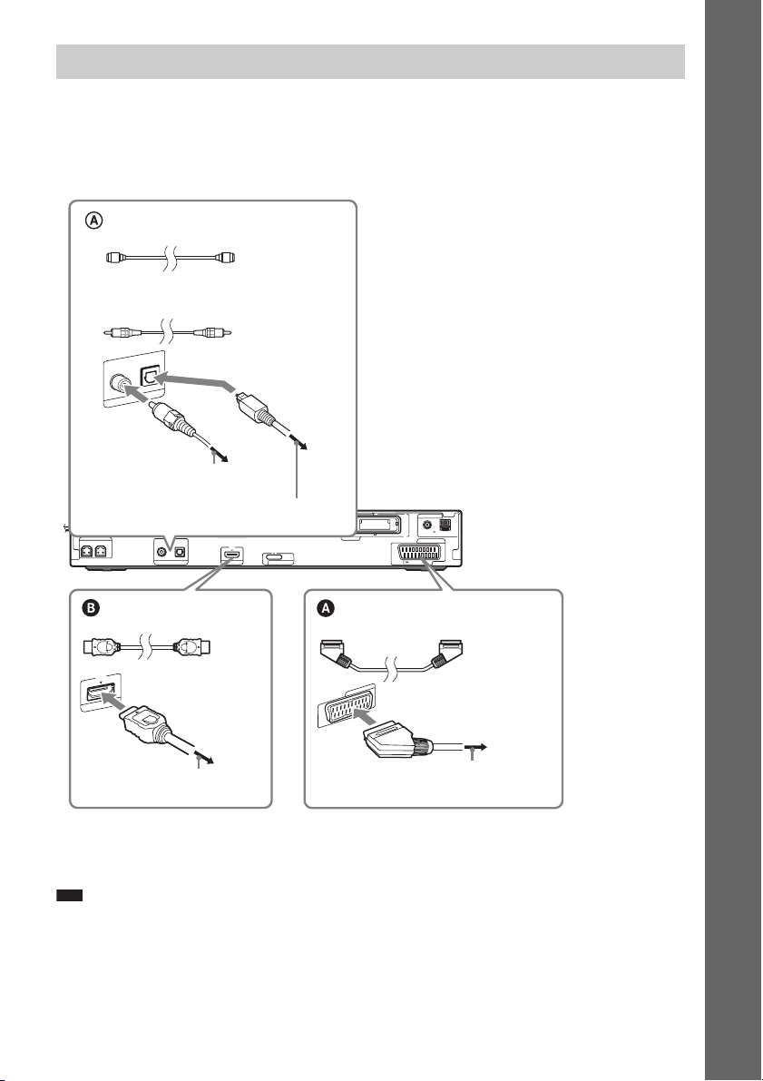
2 Connecting the TV
For video output to your TV, check the video input jacks of the TV, and select connection method A
or B. Picture quality improves in order from A (standard) to B (HDMI).
When the TV has the digital optical or coaxial output jack, you can improve sound quality by
connecting with the digital cord (A).
Digital optical cord
(not supplied)
Digital coaxial cord
(not supplied)
DIGITAL IN
COAXIAL OPTICAL
TV
To the digital coaxial output jack of
the TV
To the digital optical output jack of
the TV
SPEAKER
CENTER SUBWOOFER
COAXIAL OPTICAL
or
DIGITAL IN
TV HDMI OUT
SPEAKER
FRONT R FRONT L
ANTENNA
Rear panel
COAXIAL 75
AM
OUTPUT(TO TV)
FM
EURO AV
DC5V
0.7A MAX
DMPORT
EZW-RT10
Getting Started
HDMI* cable
(not supplied)
T
U
I O
M
D
H
To the HDMI IN jack of the TV
SCART (EURO AV) cord
(not supplied)
EURO AV
OUTPUT(TO TV)
To the SCART (EURO AV) jack of the TV
* HDMI (High-Definition Multimedia Interface)
If your TV has the HDMI jack, use this connection and select the type of output signal (page 25).
Note
• During the “DMPORT” function, video signal is not output from the HDMI OUT jack.
• The system can accept both digital and analog signals. Digital signals have priority over analog signals. (COAXIAL
has priority over OPTICAL.) If the digital signal ceases, the analog signal will be processed after 2 seconds.
15
GB
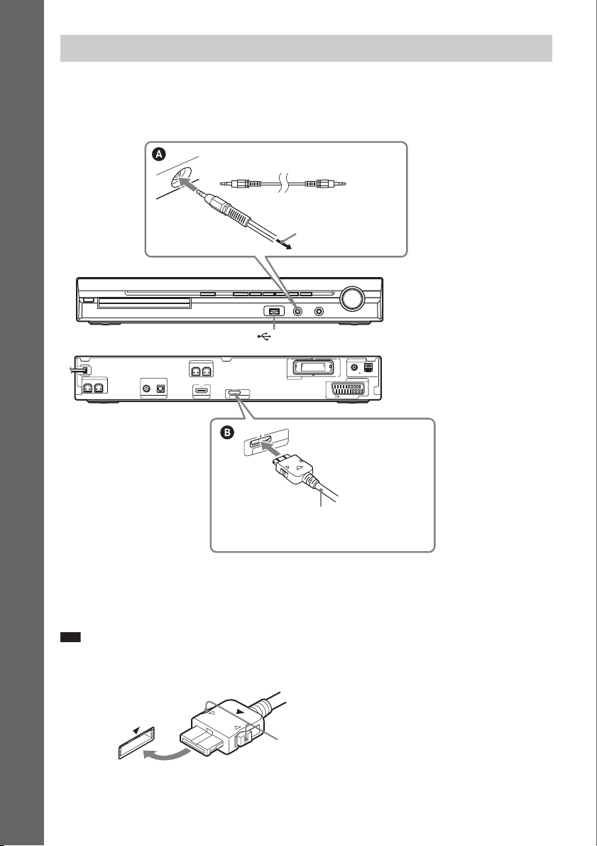
3 Connecting the other components
You can enjoy the connected component using the six speakers of the system.
• Portable audio source: A
• DIGITAL MEDIA PORT adapter: B
Getting Started
SPEAKER
CENTER SUBWOOFER
DIGITAL IN
COAXIAL OPTICAL
TV HDMI OUT
Stereo mini-plug cord
(not supplied)
To the portable audio
source
(USB) port (See page 63.)
SPEAKER
FRONT R FRONT L
DC5V
0.7A MAX
DMPORT
EZW-RT10
5V
C
D
X
A
M
A
0.7
T
R
O
P
M
D
DIGITAL MEDIA PORT adapter
(not supplied)
COAXIAL 75
OUTPUT(TO TV)
EURO AV
ANTENNA
FM
AM
Front panel
Rear panel
To connect the DIGITAL MEDIA PORT adapter
Connect a DIGITAL MEDIA PORT adapter (not supplied) to the DMPORT jack. For details, see
“Using the DIGITAL MEDIA PORT Adapter” (page 72).
Note
• Connect the DIGITAL MEDIA PORT adapter so that the V marks are aligned. When disconnecting, pull out while
pressing A.
A
GB
16
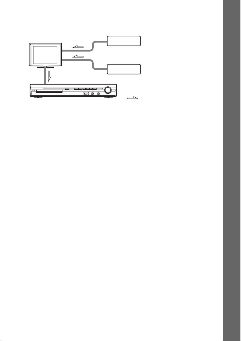
If your TV has multiple audio/video inputs
You can enjoy the sound with the speakers of the system through the connected TV. Connect the
components as follows.
TV
System
VCR, digital satellite receiver
or PlayStation, etc.
VCR, digital satellite receiver
or PlayStation, etc.
:Signal flow
Select the component on the TV. For details, refer to the operating instructions of the TV.
If the TV does not have multiple audio/video inputs, a switcher will be necessary to receive the sound
from more than two components.
Getting Started
17
GB
p
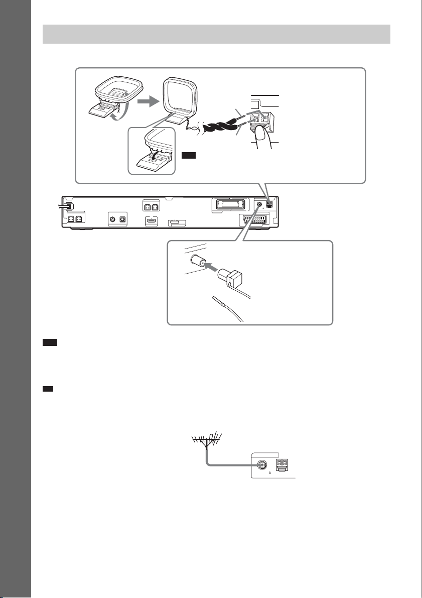
4 Connecting the antenna (aerial)
Getting Started
AM loop antenna (aerial)
(supplied)
A
B
Note
• Cord (A) or cord (B) can be connected to either terminal.
SPEAKER
CENTER SUBWOOFER
DIGITAL IN
COAXIAL OPTICAL
TV HDMI OUT
SPEAKER
FRONT R FRONT L
DC5V
0.7A MAX
DMPORT
EZW-RT10
A
N
N
TE
N
A
FM wire antenna (aerial)
(supplied)
5
7
L
IA
X
A
O
C
M
F
COAXIAL 75
OUTPUT(TO TV)
ANTENNA
FM
EURO AV
AM
Rear panel
or
Note
• Keep the AM loop antenna (aerial) and cord away from the system or other AV components, as noise may result.
• Be sure to fully extend the FM wire antenna (aerial).
• After connecting the FM wire antenna (aerial), keep it as horizontal as possible.
Ti
• Adjust the direction of the AM loop antenna (aerial) for best AM broadcast sound.
• If you have poor FM reception, use a 75-ohm coaxial cable (not supplied) to connect the unit to an outdoor FM
antenna (aerial) as shown below.
Outdoor FM antenna (aerial)
Unit
ANTENNA
COAXIAL 75
FM
AM
GB
18
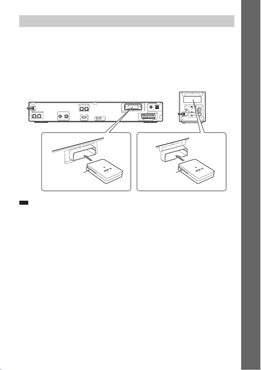
5 Inserting the wireless transceiver
You can transmit sound from the unit to an S-AIR product, such as a surround amplifier or S-AIR
receiver.
An S-AIR product is a component that is compatible with the S-AIR function.
To use the S-AIR function, you need to insert the wireless transceivers into the unit, surround amplifier,
and S-AIR receiver.
For details of the S-AIR function, see “Using an S-AIR Product” (page 73).
Rear panel of the
surround amplifier
EZW-RT
S-AIR ID
PAIRIN G
SURROUND SELECTOR
10
SPEAKER
A
B
C
L
R
SURROUND
SURROUND
BACK
Rear panel of the unit
ANTENNA
COAXIAL 75
FM
EURO AV
OUTPUT(TO TV)
transceiver
AM
Wireless
10
T
-R
W
Z
E
Note
SPEAKER
CENTER SUBWOOFER
DIGITAL IN
COAXIAL OPTICAL
TV HDMI OUT
EZW-RT10
Wireless
transceiver
SPEAKER
FRONT R FRONT L
DC5V
0.7A MAX
DMPORT
EZW-RT10
• When you insert the wireless transceiver, make sure that the AC power cord (mains lead) is not connected to a wall
outlet (mains).
• Do not touch the terminals of the wireless transceiver.
• Insert the wireless transceiver with the S-AIR logo facing up.
• Insert the wireless transceiver so that the V marks are aligned.
• Do not insert other than the wireless transceiver into the EZW-RT10 slot.
Getting Started
19
GB
p
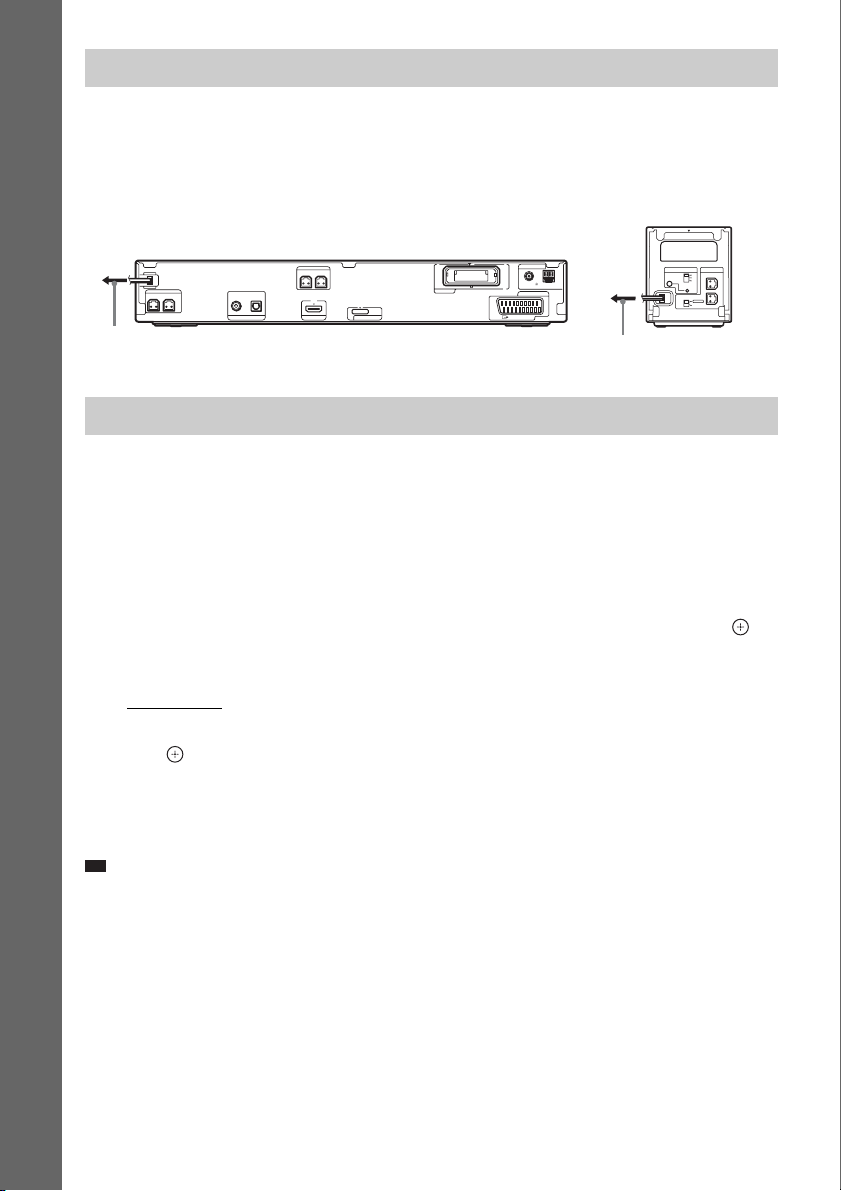
6 Connecting the AC power cords (mains lead)
Before connecting the AC power cords (mains leads) of the unit and the surround amplifier to a wall
outlet (mains), connect the front, center speakers and subwoofer to the unit and surround speakers to
the surround amplifier.
Rear panel of the
Getting Started
Rear panel of the unit
To the wall outlet (mains)
SPEAKER
CENTER SUBWOOFER
DIGITAL IN
COAXIAL OPTICAL
TV HDMI OUT
SPEAKER
FRONT R FRONT L
ANTENNA
COAXIAL 75
AM
OUTPUT(TO TV)
FM
EURO AV
DC5V
0.7A MAX
DMPORT
EZW-RT10
To the wall outlet (mains)
surround amplifier
EZW-RT
S-AIR ID
PAIRIN G
SURROUND SELECTOR
About the demonstration
After connecting the AC power cord (mains lead), the demonstration appears in the front panel display.
Setting the demonstration mode to on/off
1 Press [/1 on the unit.
The system turns on.
2 Press SYSTEM MENU.
3 Press X/x repeatedly until “DEMO” appears in the front panel display, then press or
c.
4 Press X/x to select a setting.
• “DEMO ON”: On.
• “DEMO OFF”: Off.
5 Press .
The setting is made.
6 Press SYSTEM MENU.
The system menu turns off.
Ti
• When you purchase the system from new, or if the system is at its factory default settings (ex., after performing
“COLD RESET” (page 86)), you can turn off the demonstration simply by pressing [/1 on the remote.
10
SPEAKER
A
B
C
L
R
SURROUND
SURROUND
BACK
GB
20
Step 3: Setting up the Wireless System
To use the wireless system, you need to set up
the surround amplifier. Before setting, make
sure that the wireless transceivers are inserted
into the unit and the surround amplifier correctly
(page 19).
This wireless system is called “S-AIR.” For
details of the S-AIR function, see “Using an
S-AIR Product” (page 73).
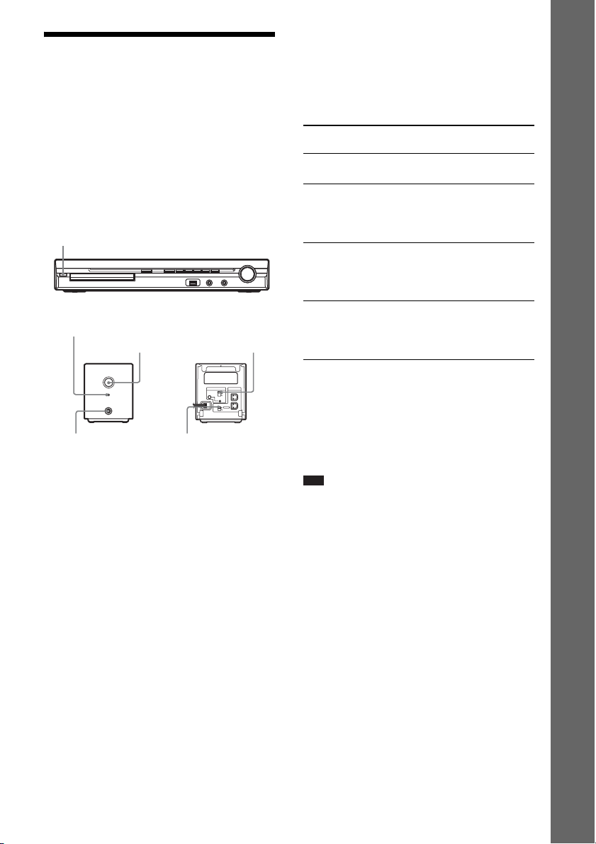
"/1
POWER / ON LINE
Indicator
POWER
POWER
POWER/ON LINE
PHONES
PHONES jack
The unit transmits sound to the surround
amplifier that is connected to the surround
speakers. To establish sound transmission,
perform the following Steps.
1 Press "/1 on the unit.
The system turns on.
2 Make sure that the SURROUND
SELECTOR switch of the surround
amplifier is set to SURROUND.
3 Set the S-AIR ID switch of the surround
amplifier to A.
4 Press POWER on the surround
amplifier.
The POWER / ON LINE indicator turns
green. If not, check the transmission status
as follows.
S-AIR ID switch
EZW-RT
10
S-AIR ID
SPEAKER
A
B
C
L
PAIRIN G
SURROUND SELECTOR
R
SURROUND
SURROUND
BACK
SURROUND
SELECTOR switch
To check the transmission status
You can check the status of sound transmission
between the unit and surround amplifier by
checking the POWER / ON LINE indicator of
the surround amplifier.
POWER / ON LINE
indicator
Turns green. Sound transmission is
Flashes green. Sound transmission is not
Turns red. The surround amplifier does
Turns off. The surround amplifier turns
Status
established.
established.
For details, see “Surround
amplifier operation” (page 97).
not output sound.
For details, see “Surround
amplifier operation” (page 97).
off or its protection is active.
For details, see “Surround
amplifier operation” (page 97).
To enjoy the sound by using
headphones
You can enjoy the system’s sound in a place
apart from the unit by connecting the
headphones to the PHONES jack on the
surround amplifier.
Note
• When you connect headphones to the surround
amplifier, neither the unit nor the surround amplifier
outputs sound from the system’s speakers.
• The volume of the unit may become minimum if you
turn off the surround amplifier while the headphones
are connected to the surround amplifier, or radio
reception is poor. In this case, “HP NO LINK” and
“VOLUME MIN” appear alternately in the front
panel display. Check radio reception, and set the
volume again.
When you use the multiple S-AIR
product
You can prevent miss transmission between the
S-AIR products by setting a different ID for each
S-AIR product. For details, see “Establishing
sound transmission between the unit and S-AIR
sub unit (ID setting)” (page 73).
Getting Started
21
GB
To prevent the transmission by
neighbors
To prevent the transmission from neighbors, you
can identify the unit and the surround amplifier
by performing the pairing operation. For details,
see “Identifying the unit with a specific S-AIR
sub unit (Pairing operation)” (page 76).
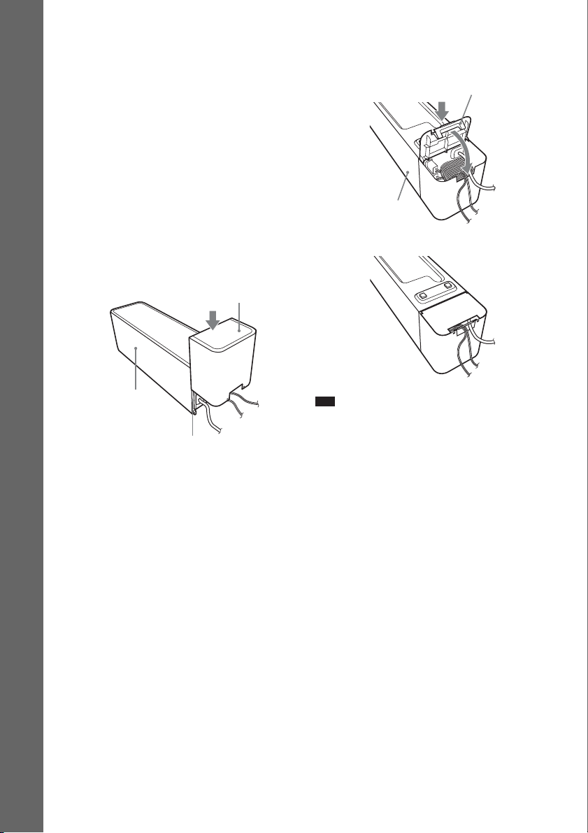
To attach the cover to the
Getting Started
surround amplifier
After connecting and setting, you can attach the
cover to the surround amplifier for organizing
and storing excess speaker cords.
1 Attach the speaker cord cover by
sliding it down along the grooves along
the edges of the surround amplifier.
Speaker cord cover
2 Insert the tabs of the speaker cord
holder in the slots of the speaker cord
cover, and press it into place.
Speaker cord holder
Surround amplifier
m
Surround amplifier
Grooves
Push the speaker cord cover down until you
hear a click. Turn the surround amplifier
upside down, then store the cords in the
speaker cord cover.
GB
22
Note
• When detaching, remove the speaker cord holder,
then remove the speaker cord cover. To remove the
speaker cord holder, slightly press the catch of the
holder and lift off. To remove the speaker cord cover,
slightly splay open the edges of the cover and slide
down.
• Do not use excessive force to store the cords.
Step 4: Performing the Quick Setup
Follow the Steps below to make the basic
adjustments for using the system.
Displayed items vary depending on the country
model.
Note
• When you connect the system and the TV with the
HDMI cable (not supplied), you need to set the type
of video output for matchi ng your TV. For details, see
“Setting the type of video output to match your TV”
(page 25).
"/1
The Setup Display for selecting the
language used in the on-screen display
appears.
LANGUAGE SETUP
OSD:
MENU:
AUDIO:
SUBTITLE:
ENGLISH
ENGLISH
FRENCH
SPANISH
PORTUGUESE
5 Press X/x to select a language.
The system displays the menu and subtitles
in the selected language.
6 Press .
The Setup Display for selecting the aspect
ratio of the TV to be connected appears.
Getting Started
C/X/x/c,
DISPLAY
1 Turn on the TV.
2 Press [/1 on the unit, and POWER on
the surround amplifier.
Note
• Make sure that the function is set to “DVD”
(page 26).
3 Switch the input selector on your TV so
that the signal from the system
appears on the TV screen.
[Press [ENTER] to run QUICK SETUP.]
appears at the bottom of the TV screen. If
this message does not appear, recall the
Quick Setup display (page 25) and perform
again.
4 Press without inserting a disc.
VIDEO SETUP
TV TYPE:
LINE:
PAUSE MODE:
4:3 LETTER BOX
16:9
16:9
4:3 PAN SCAN
7 Press X/x to select the setting that
matches your TV type.
x If you have a wide-screen TV or a 4:3
standard TV with a wide-screen mode
[16:9] (page 50)
x If you have a 4:3 standard TV
[4:3 LETTER BOX] or [4:3 PAN SCAN]
(page 50)
8 Press .
The Setup Display for selecting the output
method for video signals from the EURO
AV T OUTPUT (TO TV) jack on the rear
panel of the unit appears.
VIDEO SETUP
TV TYPE:
LINE:
PAUSE MODE:
16:9
VIDEO
VIDEO
VIDEO
RGB
VIDEO
23
GB
9 Press X/x to select the output method
for video signals.
• [VIDEO]: outputs video signals.
• [RGB]: outputs RGB signals.
Note
• If your TV does not accept RGB signals, no
picture appears on the TV screen even if you
Getting Started
select [RGB]. Refer to the operating instructions
supplied with your TV.
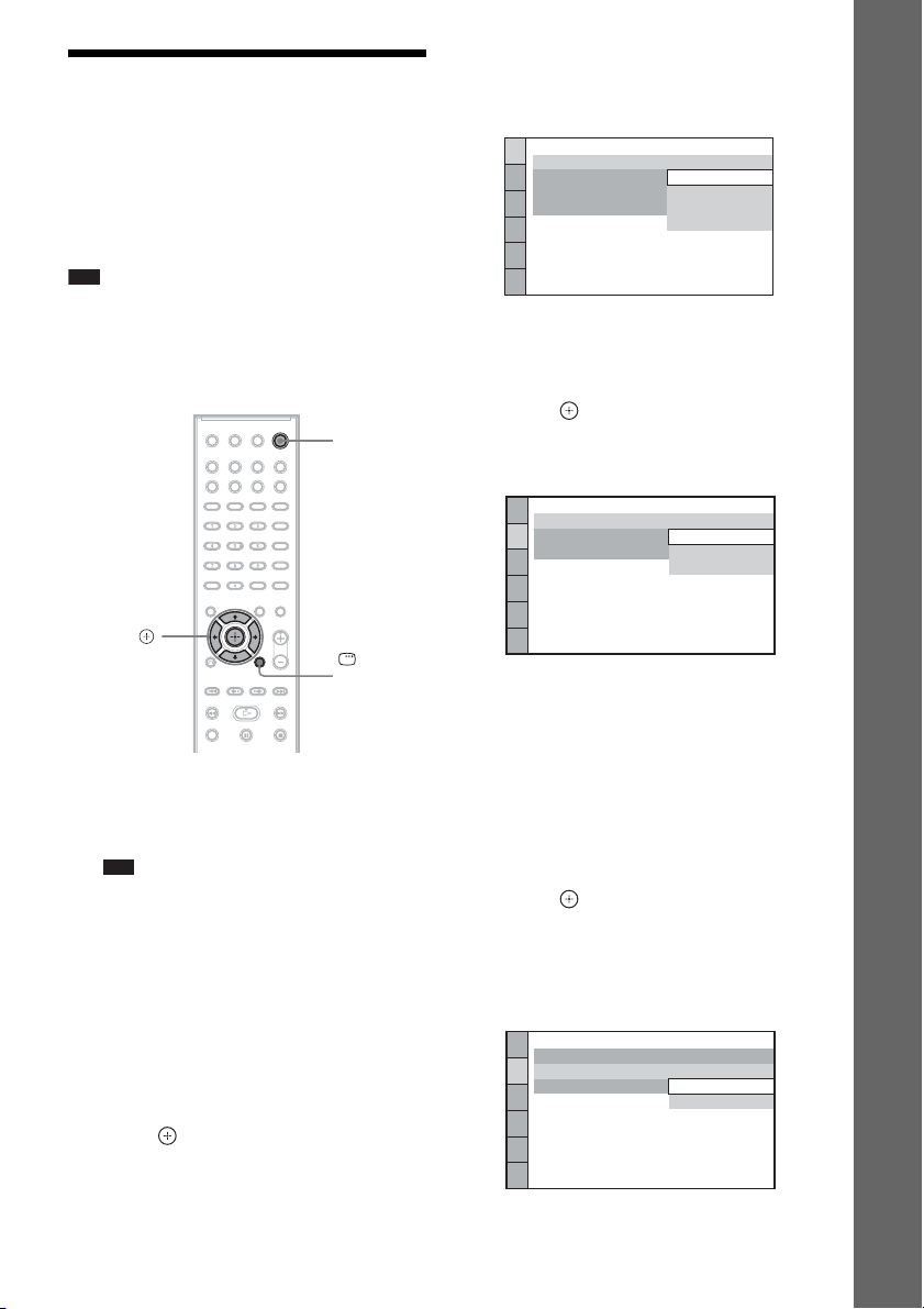
10 Press .
The Setup Display for selecting the speaker
formation appears.
11 Press C/c to select the speaker
formation image as the speakers are
actually positioned.
For details, see “Getting Optimal Surround
Sound for a Room” (page 79).
SPEAKER FORMATION
STANDARD
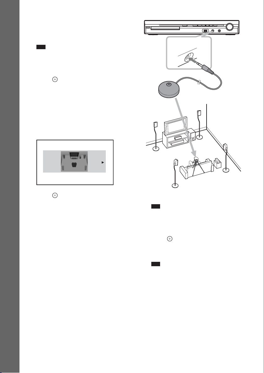
AUDIO IN / A.CAL MIC
Calibration mic
12 Press .
13 Connect the calibration mic to the
A.CAL MIC jack on the front panel.
Set up the calibration mic at the ear level
using a tripod, etc. (not supplied). The front
of each speaker should face the calibration
mic, and there should be no obstruction
between the speakers and the calibration
mic.
GB
24
14 Press C/c to select [YES].
Note
• Make sure that the headphones are not
connected to the unit or surround amplifier. You
cannot operate following Steps with the
headphones connected.
15 Press .
[AUTO CALIBRATION] starts.
Be quiet during the measurement.
Note
• Loud test sound is output when [AUTO
CALIBRATION] starts. You cannot turn the
volume down. Give consideration to children
and neighbors.
• Before [AUTO CALIBRATION], install the
surround amplifier in the appropriate location. If
you install the surroun d amplifier in an improper
location, such as another room, proper
measurement will not be obtained.
• Avoid being in the measurement area and
making noise during the measurement (which
takes about 3 minutes), as it may interfere with
measurement.
16 Unplug the calibration mic and press C/
p
c to select [YES].
Note
• The environment of the room in which the
system is installed may affect measurements.
• If measurement fails, follow the message then
retry [AUTO CALIBRATION].
17 Press .
Quick Setup is finished. All connections
and setup operations are complete.
To quit the Quick Setup
Press DISPLAY in any Step.
Ti
• If you change the position of the speakers, reset the
speaker settings. See “Getting Optimal Surround
Sound for a Room” (page 79) and “Calibrating the
Appropriate Settings Automatically” (page 80).
• If you want to change any of the settings, see “Using
the Setup Display” (page 49).
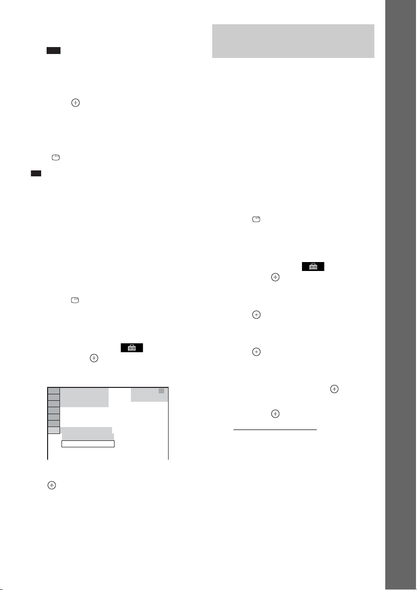
To recall the Quick Setup display
1 Press FUNCTION +/– repeatedly until
“DVD” appears in the front panel
display.
2 Press DISPLAY while the system is
in stop mode.
The Control Menu display appears on the
TV screen.
3 Press X/x to select [SETUP],
then press .
The options for [SETUP] appear.
94( 99)
1( 1)
T 0: 01: 08
CUSTOM
CUSTOM
QUICK
DVD VIDEO
4 Press X/x to select [QUICK], then press
.
The Quick Setup display appears.
Setting the type of video output to match your TV
Depending on the connection of the TV (page 15),
select the type of video output of the system.
To select the type of video signal
output from the HDMI OUT jack
When you connect the unit and the TV with the
HDMI cable, select the type of video signals
output from the HDMI OUT jack.
For details, refer also to the operating
instructions supplied with the TV/projector, etc.
1 Press FUNCTION +/– repeatedly until
“DVD” appears in the front panel
display.
2 Press DISPLAY while the system is
in stop mode.
The Control Menu display appears on the
TV screen.
3 Press X/x to select [SETUP],
then press .
The options for [SETUP] appear.
4 Press X/x to select [CUSTOM], then
press .
The Setup Display appears.
5 Press X/x to select [HDMI SETUP], then
press .
The options for [HDMI SETUP] appear.
6 Press X/x to select [HDMI
RESOLUTION], then press .
7 Press X/x to select the desired setting,
then press .
• [AUTO (1920
outputs the optimal video signal for the
connected TV.
• [1920
× 1080i* video signals.
• [1280
720p* video signals.
• [720
× 480p]**: The system outputs 720 ×
480p* video signals.
* i: interlace, p: progressive
** Depending on the country model, [720 × 480/
576p] may appear.
× 1080p)]: The system
× 1080i]: The system outputs 1920
× 720p]: The system outputs 1280 ×
Getting Started
GB
25
Step 5: Enjoying Sound
p
from all the Speakers
You can enjoy DVD, TV, or VCR sound from
all the speakers in this system.
Getting Started
X/x/c,
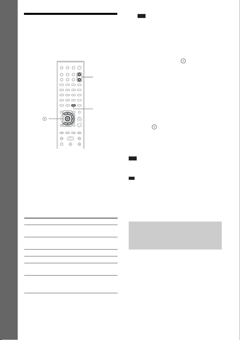
1 Press FUNCTION +/– repeatedly until
the desired function appears in the
front panel display.
Each time you press FUNCTION +/–, the
function changes as follows.
“DVD” t “TUNER FM” t “TUNER
AM” t “USB” t “TV” t “DMPORT”
t “AUDIO” t …
FUNCTION
+/–
SYSTEM
MENU
Note
• When you use th e TV (COAXIAL or OPTICAL
DIGITAL IN) jack (digital connection), the
digital connection takes priority.
2 Press SYSTEM MENU.
3 Press X/x repeatedly until “DEC.
MODE” appears in the front panel
display, then press or c.
4 Press X/x repeatedly until the
decoding mode you want appears in
the front panel display.
When you want to output the TV sound or
stereo sound of a 2 channel source from the
six speakers, select the “PRO LOGIC,”
“PLII MOVIE,” or “PLII MUSIC”
decoding mode.
For details, see page 28.
5 Press .
The setting is made.
6 Press SYSTEM MENU.
The system menu turns off.
Note
• Depending on your TV, you m ay need to t urn off your
TV’s speaker to enjoy surround sound of the system.
Ti
• When listening to audio files using a portable audio
source, you can enhance the sound.
Press FUNCTION +/– to select “AUDIO.” Connect
the portable audio source. Select “A.F.D. STD” for
“DEC. MODE.”
To cancel, select other than “A.F.D. STD.”
Function Source
“DVD” Disc that is played by the
“TUNER FM”/
“TUNER AM”
“USB” USB device (page 63)
“TV” TV
“DMPORT” DIGITAL MEDIA PORT
“AUDIO” Portable audio source (that
GB
26
system
FM/AM radio (page 56)
adapter (page 72)
is connected to the AUDIO
IN jack on the front panel)
Changing the input level of the sound from connected components
Distortion may occur when you listen to a
component connected to the EURO AV T
OUTPUT (TO TV) jack on the rear panel, or to
the AUDIO IN jack on the front panel.
Distortion is not a malfunction and will depend
on the component connected.
To prevent distortion, reduce the input level on
the unit.

1 Press FUNCTION +/– repeatedly until
“TV” or “AUDIO” appears in the front
panel display.
2 Press SYSTEM MENU.
3 Press X/x repeatedly until
“ATTENUATE” appears in the front
panel display, then press or c.
4 Press X/x to select a setting.
• “ATT ON”: You can attenuate the input
level. The output level is changed.
• “ATT OFF”: Normal input level.
5 Press .
The setting is made.
6 Press SYSTEM MENU.
The system menu turns off.
Getting Started
27
GB
Sound Adjustment
Enjoying Surround Sound by Using Decoding Mode
You can enjoy surround sound simply by selecting one of the system’s pre-programmed decoding
modes. They bring exciting and powerful sound of movie theaters into your home.
SYSTEM
X/x/c,
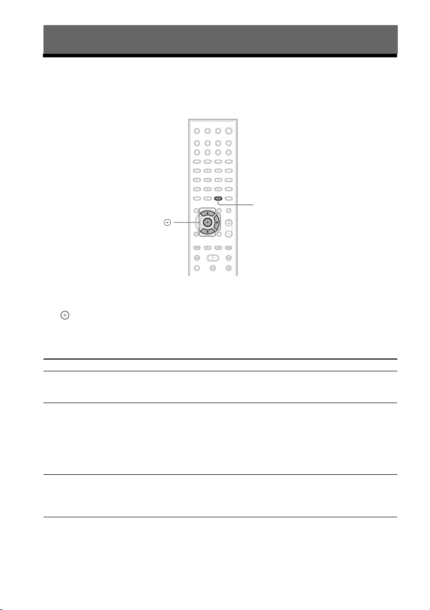
1 Press SYSTEM MENU.
2 Press X/x repeatedly until “DEC. MODE” appears in the front panel display, then press
or c.
3 Press X/x repeatedly until the decoding mode you want appears in the front panel
display.
MENU
Display Decoding mode Effect
“A.F.D. STD” AUTO FORMAT
“A.F.D. MULTI” AUTO FORMAT
“PRO LOGIC” Dolby Pro Logic Performs Pro Logic decoding to the input signal and simulates
GB
28
DIRECT
STANDARD
DIRECT MULTI
Presents sound as it was recorded/encoded.
Depending on the source, the speakers that output sound will vary.
2 channel source: Sound that is recorded in 2 channel (front left and
right channel) is also assigned to the surround left and right channel.
This mode outputs sound from the front left and right speakers,
surround left and right speakers, and subwoofer. The center speaker
does not output any sound.
Multi channel source: Depending on the source, speakers that output
the sound will vary.
surround sound from 2 channel sources.
This mode outputs sound from all the speakers and subwoofer. Sound
may not be output from all speakers depending on the source.
Display Decoding mode Effect
“PLII MOVIE” Dolby Pro Logic II
MOVIE
“PLII MUSIC” Dolby Pro Logic II
MUSIC
“2CH STEREO” 2 CHANNEL
STEREO
“HP 2CH” HEADPHONE
2 CHANNEL
STEREO
“HP VIRTUAL” HEADPHONE
VIRTUAL
Performs Pro Logic II movie mode decoding to the input signal and
produces five full-ba ndwidth output channels from 2 channe l sources.
This setting is ideal for watching videos of overdubbed or old movies.
This mode outputs sound from all the speakers and subwoofer. Sound
may not be output from all speakers depending on the source.
Performs Pro Logic II music mode decoding to the input signal and
produces five full-ba ndwidth output channels from 2 channe l sources.
This setting is ideal for normal stereo sources such as a CD.
This mode outputs sound from all the speakers and subwoofer. Sound
may not be output from all speakers depending on the source.
Outputs the sound from the front left and right speakers and
subwoofer. Multi channel surround formats are downmixed to 2
channels.
Outputs the sound from headphone left and right. Multi channel
surround formats are downmixed to 2 channels.
Outputs the sound as surround from headphone left and right. This
mode is effective only when a multi channel source is played.
4 Press .
The setting is made.
5 Press SYSTEM MENU.
The system menu turns off.
To turn the surround effect off
Select “A.F.D. STD” or “2CH STEREO” for “DEC. MODE.”
Note
• When the input signal is multi channel source, “PRO LOGIC,” “PLII MOVIE,” and “PLII MUSIC” are canceled
and the multi channel source is output directly.
• When the bilingual broadcast sound is input, “PRO LOGIC,” “PLII MOVIE,” and “PLII MUSIC” are not effective.
• You cannot select the decoding mode when the unit is reading the files in the USB device or recording/copying
songs.
• Depending on the input stream, the decoding mode may not be effective.
• When you select “A.F.D. MULTI,” the surround or stereo effect may not be effective. In this case, select “A.F.D.
STD,” “PRO LOGIC,” “PLII MOVIE,” or “PLII MUSIC.”
• When changing the decoding mode while using the S-AIR receiver, sound from the S-AIR receiver may skip.
Sound Adjustment
29
GB
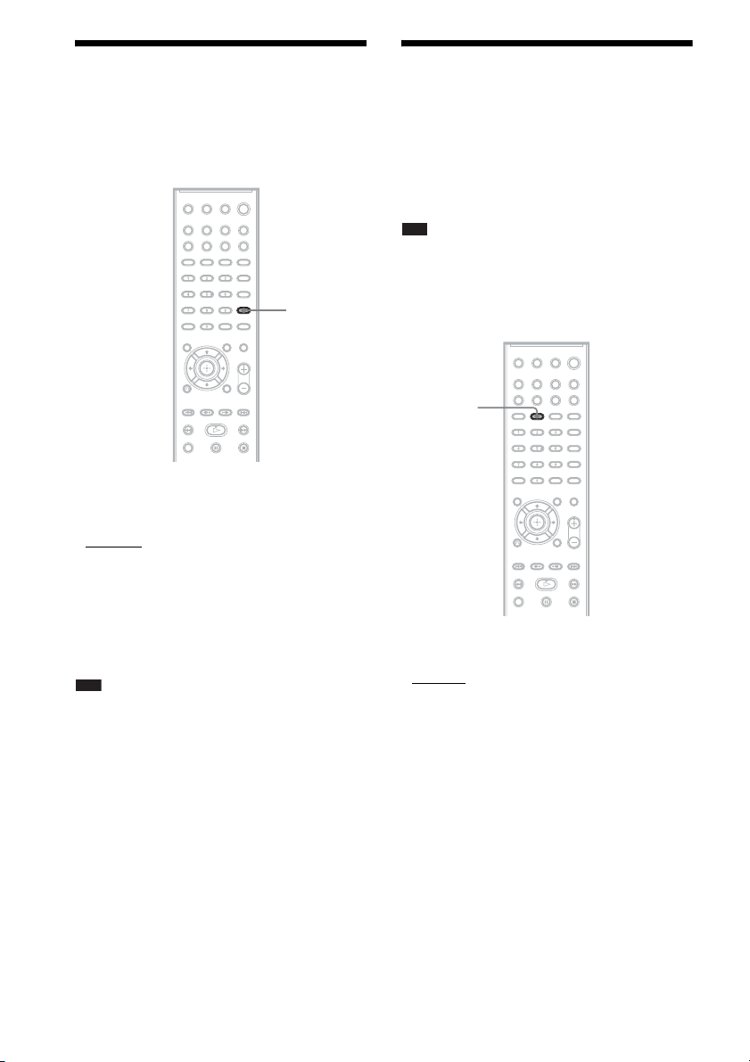
Selecting the Sound
Enjoying Multiplex
Mode
You can select a suitable sound mode for movies
or music.
SOUND
MODE
Press SOUND MODE repeatedly during
playback until the desired mode appears in
the front panel display.
• “AUTO”: The system selects “MOVIE” or
“MUSIC” automatically to produce the sound
effect depending on the disc.
• “MOVIE”: The system provides the sound for
movies.
• “MUSIC”: The system provides the sound for
music.
Note
• You cannot operate these setup items when you
connect headphones to the unit or surround amplifier.
• When changing the sound mode while using the
S-AIR receiver, sound from the S-AIR receiver may
skip.
Broadcast Sound
(DUAL MONO)
You can enjoy multiplex broadcast sound when
the system receives or plays the Dolby Digital
multiplex broadcast signal.
Note
• To receive the Dolby Digital signal, you need to
connect a TV or other component to the unit with an
optical or coaxial digital cord (page 15) and set the
digital output mode of the TV or other component to
Dolby Digital.
AUDIO
Press AUDIO repeatedly until the desired
signal appears in the front panel display.
•“MAIN”: Sound of the main language will be
output.
• “SUB”: Sound of the sub language will be
output.
• “MAIN+SUB”: Mixed sound of both the main
and sub languages will be output.
30
GB
 Loading...