

Sony CDX-GT317EE, CDX-GT360 Schematic
CDX-GT317EE/GT360
SERVICE MANUAL
Ver. 1.1 2007.03
(Photo: CDX-GT317EE)
• The tuner and CD sections have no adjustments.
SPECIFICATIONS
CD player section
Signal-to-noise ratio 120 dB
Frequency response 10 – 20,000 Hz
Wow and flutter Below measurable limit
Tuner section
FM
Tuning range GT317EE:
FM1/FM2: 87.5 – 108.0 MHz
(at 50 kHz step)
FM3: 65 – 74 MHz (at 30 kHz step)
GT360:
87.5 – 108.0 MHz
Antenna terminal External antenna connector
Intermediate frequency 10.7 MHz/450 kHz
Usable sensitivity 9 dBf
Selectivity 75 dB at 400 kHz
Signal-to-noise ratio 67 dB (stereo), 69 dB (mono)
Harmonic distortion at 1 kHz
0.5% (stereo), 0.3% (mono)
Separation 35 dB at 1 kHz
Frequency response 30 – 15,000 Hz
Saudi Arabia Model
CDX-GT360
East European Model
CDX-GT317EE
Model Name Using Similar Mechanism CDX-GT262/GT217
CD Drive Mechanism Type MG-101TA-188//Q
Optical Pick-up Name DAX-25A
MW/LW (GT317EE)
Tuning range MW: 531 – 1,602 kHz
LW: 153 – 279 kHz
Antenna terminal External antenna connector
Intermediate frequency 10.7 MHz/450 kHz
Sensitivity MW: 30 µV, LW: 40 µV
MW/SW (GT360)
Tuning range MW: 531 – 1,602 kHz
SW1: 2,940 – 7,735 kHz
SW2: 9,500 – 18,135 kHz
(except for 10,140 – 11,575 kHz)
Antenna terminal External antenna connector
Intermediate frequency 10.7 MHz/450 kHz
Sensitivity 30 µV
Power amplifier section
Outputs Speaker outputs (sure seal connectors)
Speaker impedance 4 – 8 ohms
Maximum power output
GT317EE: 50 W × 4 (at 4 ohms)
GT360: 52 W × 4 (at 4 ohms)
9-887-460-02
2007C04-1
© 2007.03
– Continued on next page –
FM/MW/LW COMPACT DISC PLAYER
CDX-GT317EE
FM/MW/SW COMPACT DISC PLAYER
CDX-GT360
Sony Corporation
eVehicle Division
Published by Sony Techno Create Corporation
CDX-GT317EE/GT360
General
Outputs Audio outputs terminal (sub/rear switchable)
Inputs Telephone ATT control terminal (GT317EE)
Tone controls Low: ±10 dB at 60 Hz (XPLOD)
Power requirements 12 V DC car battery (negative ground)
Dimensions Approx. 178 × 50 × 179 mm
Mounting dimensions Approx. 182 × 53 × 162 mm
Mass Approx. 1.2 kg (2 lb. 11 oz.)
Supplied accessories Card remote commander: RM-X151
Design and specifications are subject to change without
notice.
Power antenna relay control terminal
Power amplifier control terminal
BUS control input terminal
BUS audio input terminal
Antenna input terminal
AUX input jack (stereo mini jack)
Mid: ±10 dB at 1 kHz (XPLOD)
High: ±10 dB at 10 kHz (XPLOD)
(7
1/8 × 2 × 7 1/8 in.) (w/h/d)
(7 1/4 × 2 1/8 × 6 1/2 in.) (w/h/d)
Parts for installation and connections (1 set)
SERVICE NOTES
NOTES ON HANDLING THE OPTICAL PICK-UP BLOCK
OR BASE UNIT
The laser diode in the optical pick-up block may suffer electrostatic
breakdown because of the potential difference generated by the
charged electrostatic load, etc. on clothing and the human body.
During repair, pay attention to electrostatic breakdown and also use
the procedure in the printed matter which is included in the repair
parts.
The flexible board is easily damaged and should be handled with
care.
Notes on Chip Component Replacement
•Never reuse a disconnected chip component.
•Notice that the minus side of a tantalum capacitor may be damaged
by heat.
TEST DISCS
Please use the following test discs for the check on the CD section.
YDES-18 (Part No. 3-702-101-01)
PATD-012 (Part No. 4-225-203-01)
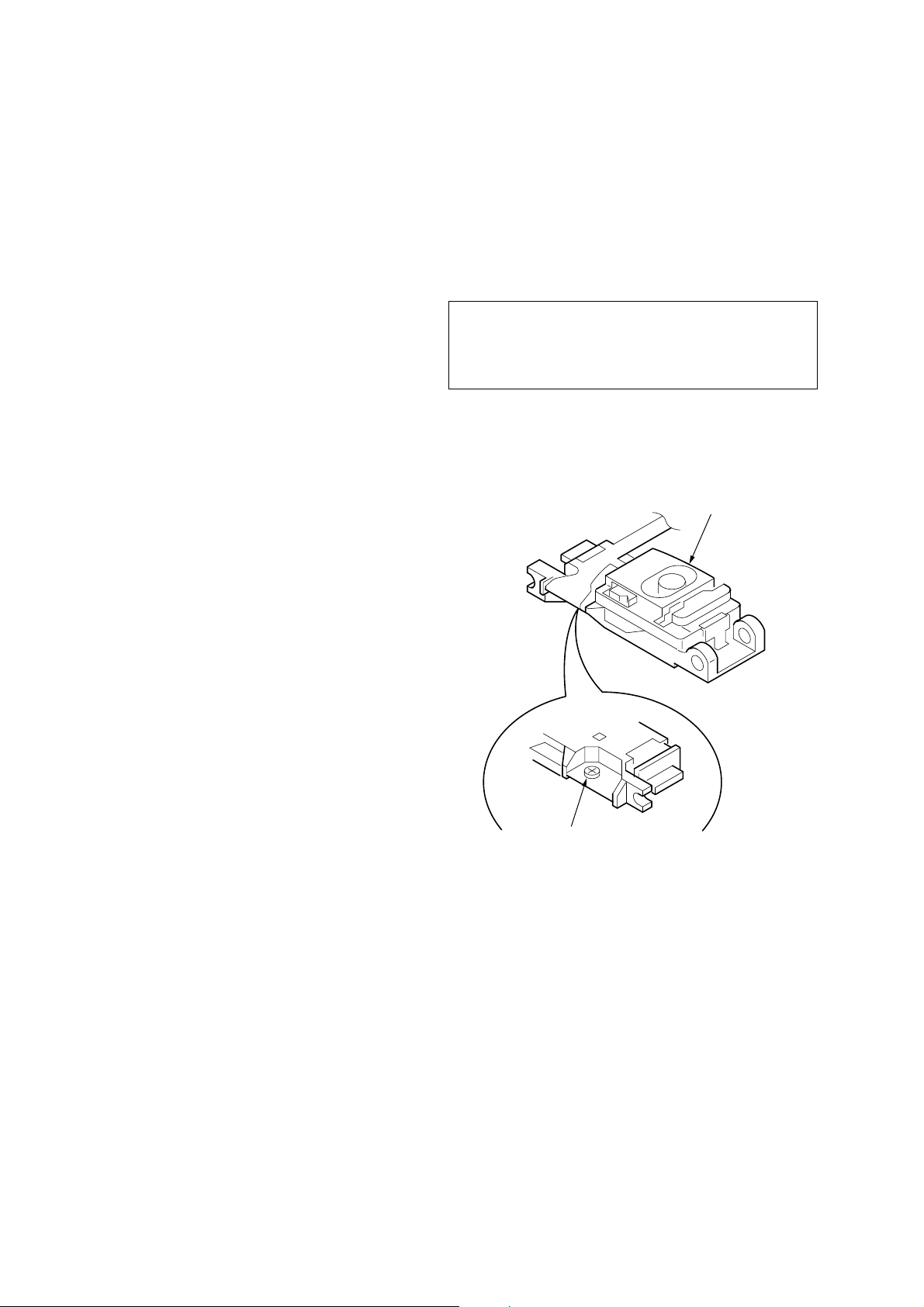
CAUTION
Use of controls or adjustments or performance of procedures
other than those specified herein may result in hazardous
radiation exposure.
If the optical pick-up block is defective, please replace the whole
optical pick-up block.
Never turn the semi-fix ed resistor located at the side of optical pickup block.
optical pick-up
NOTES ON LASER DIODE EMISSION CHECK
The laser beam on this model is concentrated so as to be focused on
the disc reflective surface by the objective lens in the optical pickup block. Therefore, when checking the laser diode emission,
observe from more than 30 cm away from the objective lens.
SAFETY-RELATED COMPONENT WARNING!!
COMPONENTS IDENTIFIED BY MARK 0 OR DOTTED LINE
WITH MARK 0 ON THE SCHEMATIC DIAGRAMS AND IN
THE PARTS LIST ARE CRITICAL TO SAFE OPERATION.
REPLACE THESE COMPONENTS WITH SONY PARTS
WHOSE PART NUMBERS APPEAR AS SHOWN IN THIS
MANUAL OR IN SUPPLEMENTS PUBLISHED BY SONY.
semi-fixed resistor
2
CDX-GT317EE/GT360
D
This compact disc player is classified as a CLASS 1 LASER
product. The CLASS 1 LASER PRODUCT label is located on the
exterior.
This label is located on the bottom of the chassis.
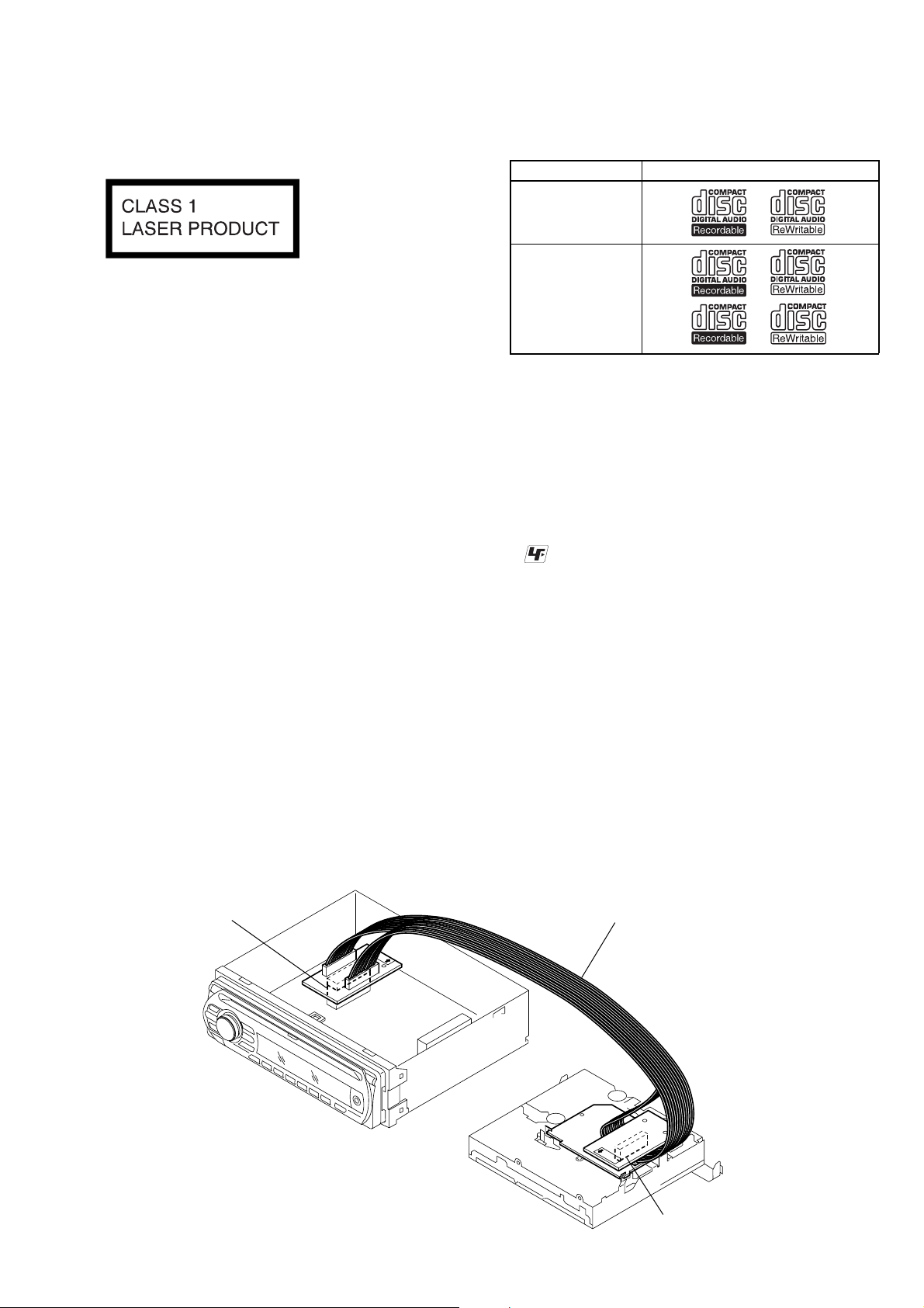
EXTENSION CABLE AND SERVICE POSITION
When repairing or servicing this set, connect the jig (extension cable)
as shown below.
• Connect the MAIN board (CN350) and the SER V O board (CN2)
with the extension cable (Part No. J-2502-076-1).
• CD playback
You can play CD-DA (also containing CD TEXT*), CD-R/CDRW (MP3/WMA files also containing Multi Session .
Type of discs Label on the disc
CD-DA
MP3
WMA
*A CD TEXT disc is a CD-DA that includes information such as
disc, artist and track name.
UNLEADED SOLDER
•
Boards requiring use of unleaded solder are printed with the leadfree mark (LF) indicating the solder contains no lead.
(Caution:Some printed circuit boards may not come printed with
the lead free mark due to their particular size.)
: LEAD FREE MARK
Unleaded solder has the following characteristics.
• Unleaded solder melts at a temperature about 40°C higher than
ordinary solder.
Ordinary soldering irons can be used but the iron tip has to be
applied to the solder joint for a slightly longer time.
Soldering irons using a temperature regulator should be set to
about 350°C.
Caution:The printed pattern (copper foil) may peel away if the
heated tip is applied for too long, so be careful!
• Strong viscosity
Unleaded solder is more viscous (sticky, less prone to flow)
than ordinary solder so use caution not to let solder bridges
occur such as on IC pins, etc.
• Usable with ordinary solder
It is best to use only unleaded solder but unleaded solder may
also be added to ordinary solder.
MAIN BOARD
CN350
J-2502-076-1
SERVO BOAR
CN2
3
CDX-GT317EE/GT360
k
Ver. 1.1
NOTE FOR REPLACEMENT OF THE SERVO BOARD
When repairing, the complete SER VO board (A-1177-201-A) should
be replaced since any parts in the SER V O board cannot be repaired.
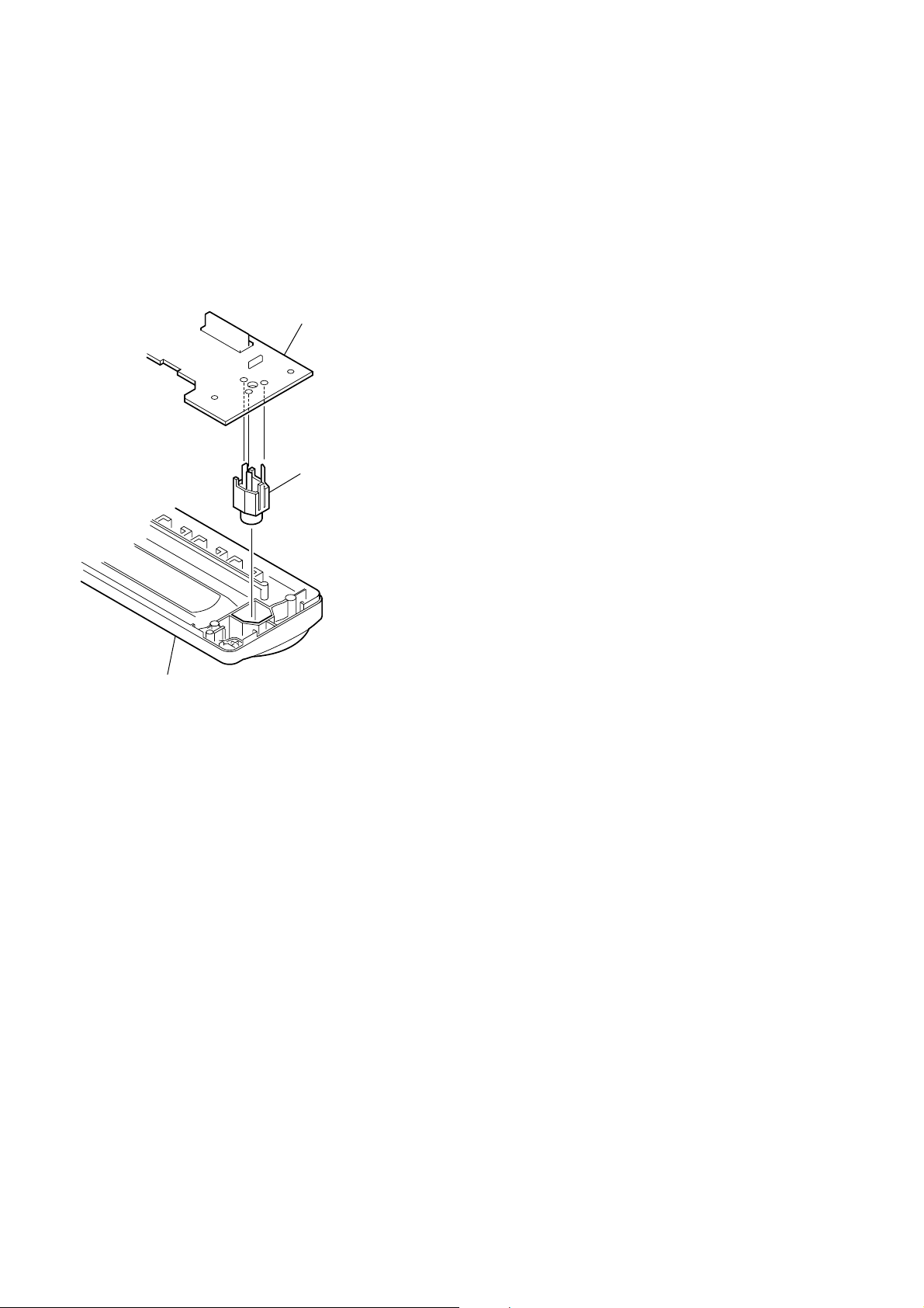
NOTE FOR REPLACEMENT OF THE AUX JACK (J901)
To replace the AUX jack requires alignment.
1. Insert the AUX jack into the KEY board.
2. Place the KEY board on the front panel.
3. Solder the three terminals of the jack.
KEY board
AUX jac
TABLE OF CONTENTS
1. GENERAL
Location of Controls........................................................ 5
Connections ..................................................................... 6
2. DISASSEMBLY
2-1. Sub Panel (FL) Assy........................................................ 11
2-2. CD Mechanism Block ..................................................... 11
2-3. Main Board...................................................................... 12
2-4. Servo Board ..................................................................... 12
2-5. Chassis (T) Sub Assy....................................................... 13
2-6. Roller Arm Assy .............................................................. 13
2-7. Chassis (OP) Assy ........................................................... 14
3. DIAGNOSIS FUNCTION ........................................ 15
4. DIAGRAMS
4-1. Block Diagram –Main Section– ...................................... 17
4-2. Block Diagram –Display Section– .................................. 18
4-3. Printed Wiring Board –Main Section– ............................ 20
4-4. Schematic Diagram –Main Section (1/3)– ...................... 21
4-5. Schematic Diagram –Main Section (2/3)– ...................... 22
4-6. Schematic Diagram –Main Section (3/3)– ...................... 23
4-7. Printed Wiring Board –Key Section– .............................. 24
4-8. Schematic Diagram –Key Section–................................. 25
front panel
5. EXPLODED VIEWS
5-1. Main Section.................................................................... 30
5-2. Front Panel Section ......................................................... 31
5-3. CD Mechanism Section (MG-101TA-188//Q) ................ 32
6. ELECTRICAL PARTS LIST.................................. 33
4
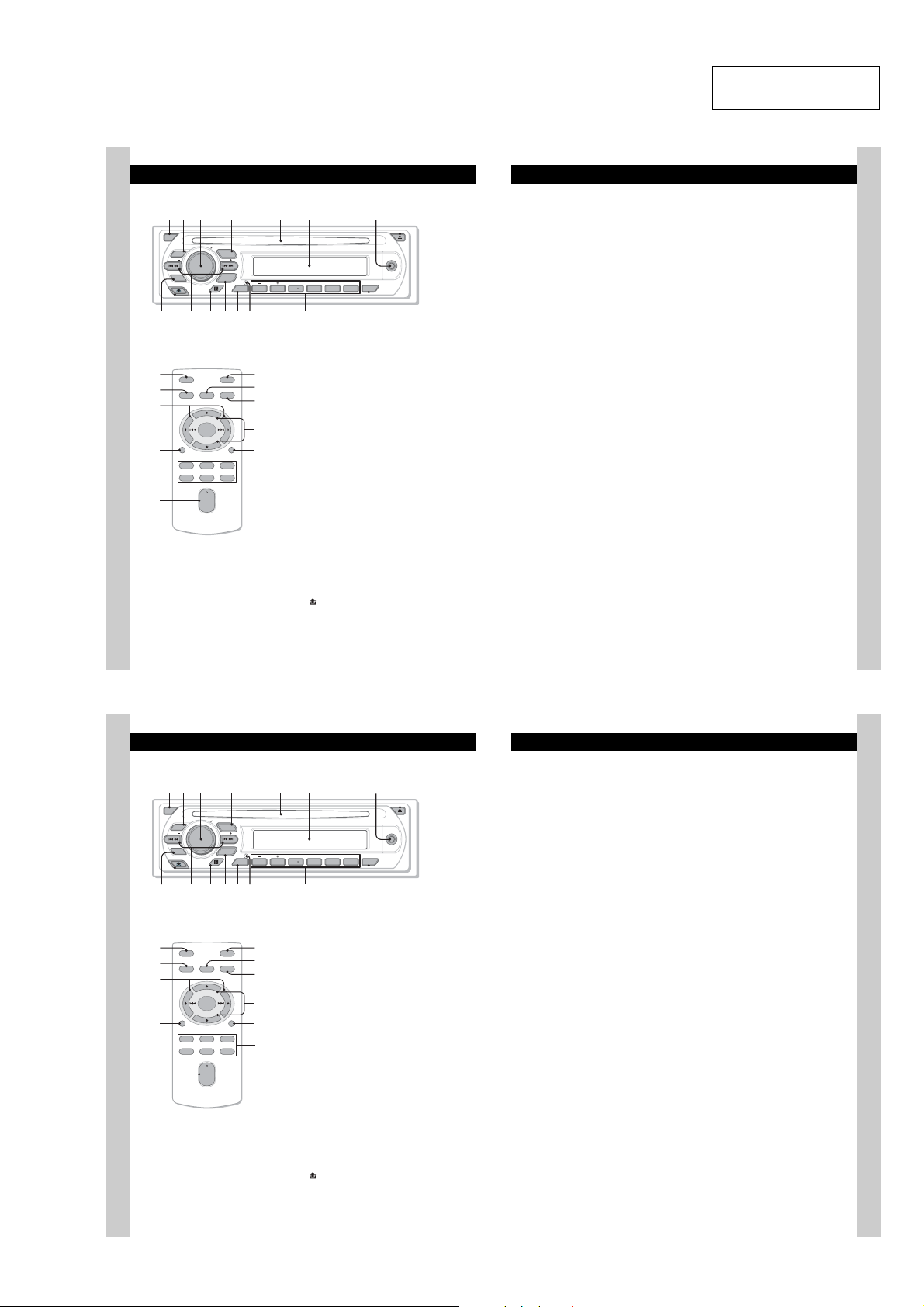
• LOCATION OF CONTROLS
1 2
4 5 8673
1 2
q
q
4 5 8673
qaq
q;9 qsqfq
• CDX-GT317EE
Location of controls and basic operations
Main unit
OFF
Card remote commander
RM-X151
1
4
qk
qf
ql
PUSH SELECT
EQ3
SEEK
PTY
qa qdq;9 qs qfqg
OFF
SEL
SOURCE
+
–
DSPL
132
465
+
VOL
–
SOURCE
SEEK
MODE
ALBMDIM REP SHUF
123456
DSPL
w;
ATT
wa
MODE
qd
ws
SCRL
wd
wf
Refer to the pages listed for details. The
corresponding buttons on the card remote
commander control the same functions as those
on the unit.
A OFF button
B EQ3 (equalizer) button 11
C Volume control dial/select button 11
D SOURCE button
E Disc slot
F Display window
G AUX input jack 12
H Z (eject) button
I PTY (Program Type) button 10
J (front panel release) button 5
AUX
PAUSE
AF/TA
CDX-GT317EE
qjqh
To po we r off; stop the source.
To select an equalizer type (XPLOD,
VOCAL, EDGE, CRUISE, SPACE,
GRAVITY, CUSTOM or OFF).
To ad ju st vo lume (rotate); select setup items
(press and rotate).
To po wer on; change the source (Radio/CD/
1
MD*
/AUX).
Insert the disc (label side up), playback
starts.
To co nnect a portabl e audio device.
To ej e c t the disc.
To se lect PTY in RDS.
SECTION 1
GENERAL
CDX-GT317EE/GT360
K SEEK –/+ buttons
CD:
To sk ip tracks (press); skip tracks
continuously (press, then press again within
about 1 second and hold); reverse/fastforward a track (press and hold).
Radio:
To tune in stations automatically (press); find
a station manually (press and ho ld).
L Receptor for th e card remote
commander
M MODE button 8, 12
To se le ct the radio band (FM/MW/LW);
2
select the unit*
N DSPL (display)/DIM (dimmer) button
8, 9
To ch ange display item s (press); change the
display brightness (press and hol d) .
O RESET button (located behind the front
panel) 4
P Number buttons
CD/MD*
(1)/(2): ALBM –/+*
(3): REP 8
(4): SHUF 8
(6): PAUS E*
Radio:
To re ce ive stored stations (press); store
stations (press and hold).
Q AF (Alternative Frequencies)/TA
(Traffic Announcement) button 9
To se t AF and TA in RDS.
.
1
:
To s kip albums (press); skip albums
continuously (press and hold) .
To p ause playback. To cancel, press
again.
3*4
5
This section is extracted
from instruction manual.
The following buttons on the card remote
commander have also different buttons/functions
from the unit. Remove the insulation film before
use (page 4).
qk < (.)/, (>) buttons
To control CD/radio, the same as (SEEK)
–/+ on the unit.
ql VOL (volume) +/– button
To adjust volume.
w; AT T (attenuate) button
To att e nuate the sound. To cancel, press
again.
wa SEL (select) button
The same as the select button on the unit.
ws M (+)/m (–) buttons
To control CD, the same as (1)/(2)
(ALBM –/+) on the unit.
wd SCRL (scroll) button 8
To s c roll the display item.
wf Number buttons
To r e c e ive stored st at ions (press); store
stations (press and hold).
*1
When an MD changer is connected.
*2
When a CD/MD changer is connected.
*3
When an MP3/WMA is played.
*4
If the changer is connected, the operation is
different, see page 13.
*5
When playing bac k on this unit.
Note
If the unit is turned off and the display disappears, it
cannot be operated with the card remote commander
unless
(SOURCE)
inserted to activate the unit first.
Tip
For details on how to replace the battery, see
“Replacing the lithium battery of the card remote
commander” on page 15.
on the unit is pressed, or a disc is
6
• CDX-GT360
6
Location of controls and basic operations
Main unit
OFF
Card remote commander
RM-X151
1
4
qk
qf
ql
PUSH SELECT
EQ3
SOURCE
OFF
SOURCE
DSPL
132
465
SEEK
MODE
ALBMDIM REP SHUF
123456
DSPL
d
g
Refer to the pages listed for details. The
corresponding buttons on the card remote
commander control the same functions as those
on the unit.
w;
ATT
SEL
MODE
+
–
SCRL
+
VOL
–
A OFF button
wa
B EQ3 (equalizer) button 9
qd
ws
C Volume control dial/select button 9
qj
D SOURCE button
wd
E Disc slot
SEEK
BTM
F Display window
G AUX input jack 10
H Z (eject) button
I BTM button 8
J (front panel release) button 5
AUX
PAUSE
SCRL
CDX-GT360
h
j
To po we r off; stop the source.
To select an equalizer type (XPLOD,
VOCAL, EDGE, CRUISE, SPACE,
GRAVITY, CUSTOM or OFF).
To ad ju st vo lume (rotate); select setup items
(press and rotate).
To po we r on; change the sour ce (Radio/CD/
1
MD*
/AUX).
Insert the disc (label side up), playback
starts.
To co nnect a portabl e audio device.
To ej e c t the disc.
To st art t he BTM function (press and ho ld).
K SEEK –/+ buttons
CD:
To sk ip tracks (press); skip tracks
continuously (press, then press again within
about 1 second and hold); reverse/fastforward a track (press and hold).
Radio:
To tune in stations automatically (press); find
a station manually (press and ho ld).
L Receptor for th e card remote
commander
M MODE button 8, 11
To se le ct the radio band (FM/MW/SW);
2
select the unit*
N DSPL (display)/DIM (dimmer) button
8
To ch ange display item s (press); change the
display brightness (press and hol d) .
O RESET button (located behind the front
panel) 4
P Number buttons
CD/MD*
(1)/(2): ALBM –/+*
(3): REP 8
(4): SHUF 8
(6): PAUS E*
Radio:
To re ce ive stored stations (press); store
stations (press and hold).
Q SCRL (scroll) button 8
To sc ro ll th e display item.
.
1
:
To s kip albums (press); skip albums
continuously (press and hold) .
To p ause playback. To cancel, press
again.
3*4
5
The following buttons on the card remote
commander have also different buttons/functions
from the unit. Remove the insulation film before
use (page 4).
qk < (.)/, (>) buttons
To control CD/radio, the same as (SEEK)
–/+ on the unit.
ql VOL (volume) +/– button
To adjust volume.
w; AT T (attenuate) button
To att e nuate the sound. To cancel, press
again.
wa SEL (select) button
The same as the select button on the unit.
ws M (+)/m (–) buttons
To control CD, the same as (1)/(2)
(ALBM –/+) on the unit.
wd Number buttons
To r e c e ive stored st ations (press); store
stations (press and hold).
*1
When an MD changer is connected.
*2
When a CD/MD changer is connected.
*3
When an MP3/WMA is played.
*4
If the changer is connected, the operation is
different, see page 11.
*5
When playing bac k on this unit.
Note
If the unit is turned off and the display disappears, it
cannot be operated with the card remote commander
unless
(SOURCE)
inserted to activate the unit first.
Tip
For details on how to replace the battery, see
“Replacing the lithium battery of the card remote
commander” on page 13.
on the unit is pressed, or a disc is
7
7
5
CDX-GT317EE/GT360
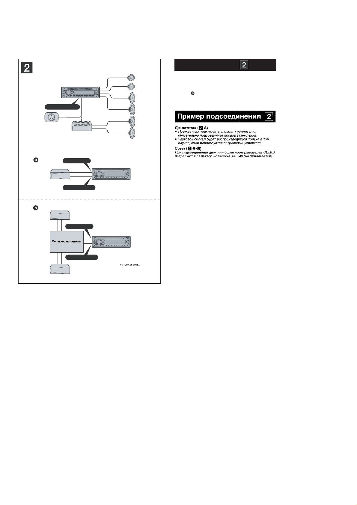
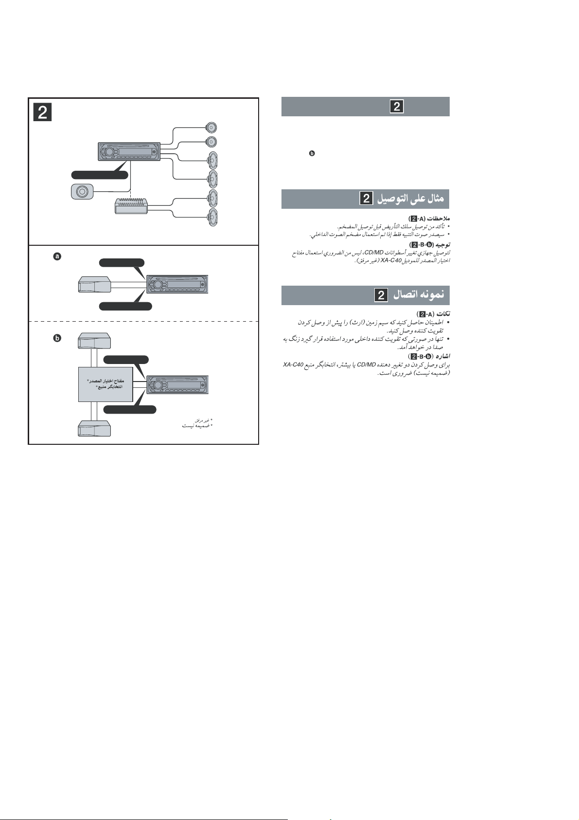
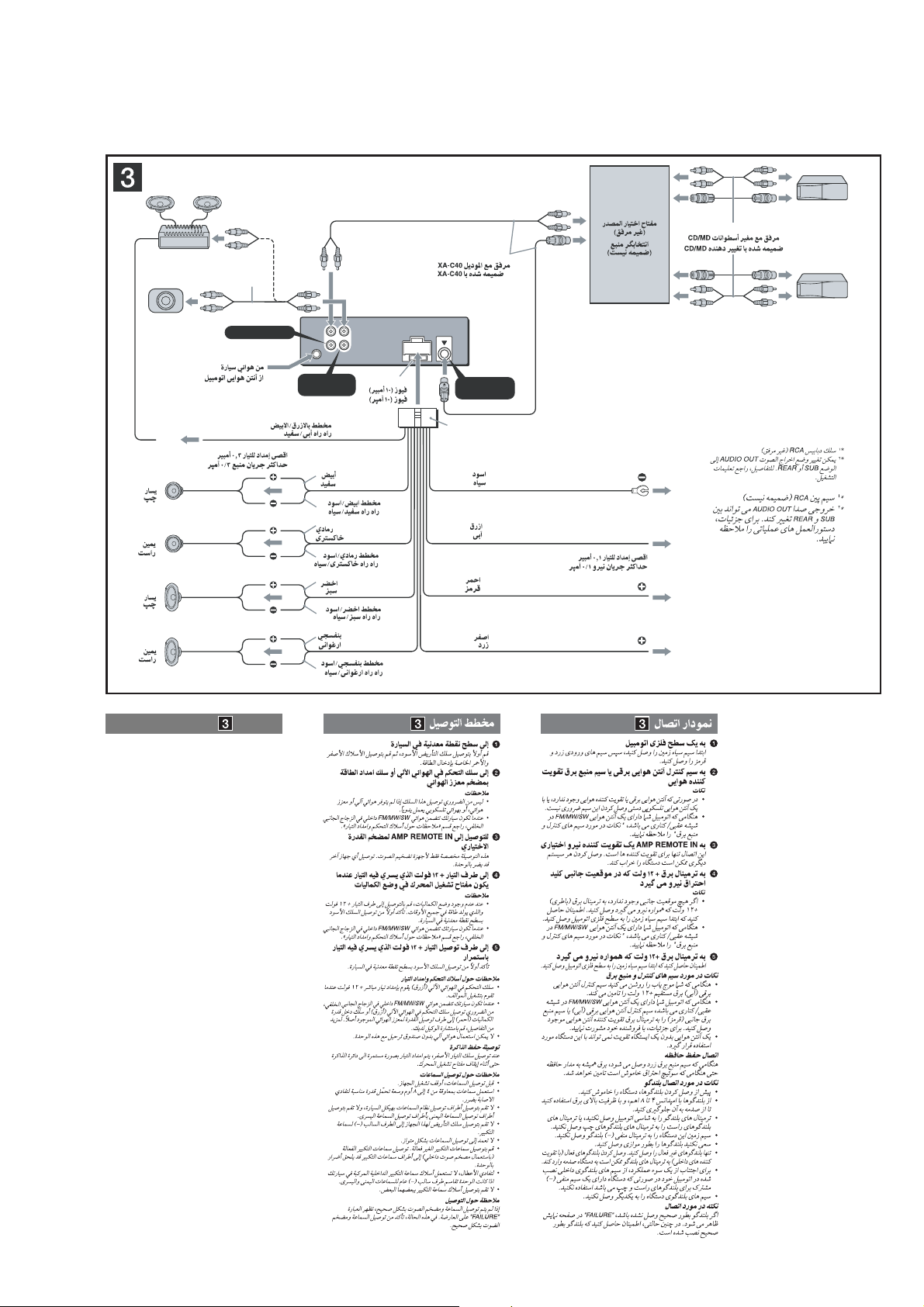
• CONNECTIONS
• CDX-GT317EE
A
AUDIO OUT REAR
*
AUDIO OUT SUB/REAR
*
Connection example
Notes
(2-A)
•
Be sure to connect the ground (earth) lead before connecting
the amplifi er.
•
The alarm will only sound if the built-in amplifi er is used.
(2-B-
Tip
For connecting two or more CD/MD changers, the source
selector XA-C40 (not supplied) is necessary.
)
B
BUS AUDIO IN
BUS CONTROL IN
BUS AUDIO IN
Source selector*
XA-C40
BUS CONTROL IN
*
not supplied
*
6
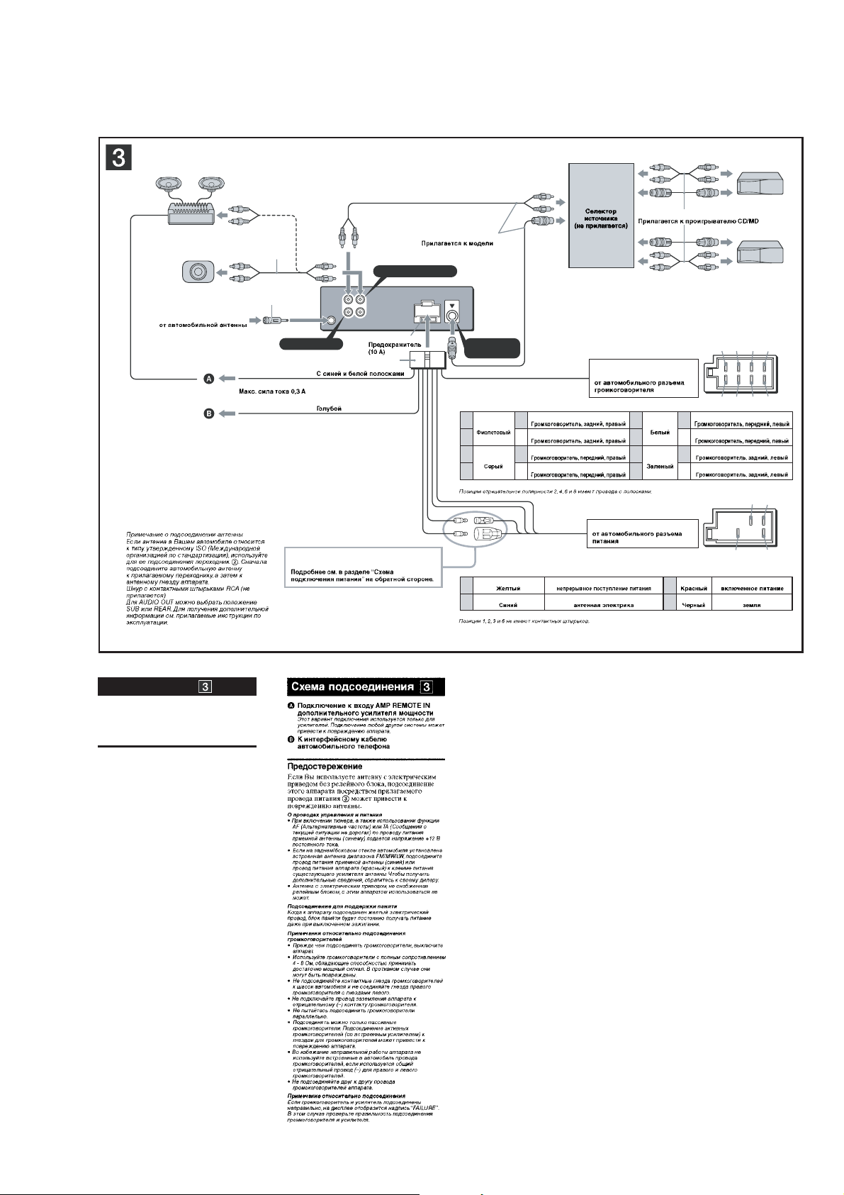
CDX-GT317EE/GT360
L
R
AUDIO OUT
REAR/SUB
BUS
IN
BUS
CONTROL IN
13 57
24 68
57
48
AUDIO OUT REAR
*
3
BUS AUDIO IN
Negative polarity positions 2, 4, 6, and 8 have striped leads.
1
Purple
+
Speaker, Rear, Right
5
White
+
Speaker, Front, Left
2–
Speaker, Rear, Right
6–
Speaker, Front, Left
3
Grey
+
Speaker, Front, Right
7
Green
+
Speaker, Rear, Left
4–
Speaker, Front, Right
8–
Speaker, Rear, Left
AMP REM
Max. supply current 0.3 A
Fuse (10 A)
Blue/white striped
Light blue
from the car’s power connector
See “Power connection diagram” on the reverse
side for details.
Positions 1, 2, 3, and 6 do not have pins.
from the car’s speaker
connector
ATT
*
2
Source selector
(not supplied)
XA-C40
4
Yellow continuous power supply
7
Red switched power supply
5
Blue power antenna (aerial) control
8
Black ground (earth)
Supplied with the CD/MD changer
from car antenna (aerial)
*
1
*
1
Note for the aerial connecting
If your car aerial is an ISO (International
Organization for Standardization) type, use the
supplied adaptor
2
to connect it. First connect
the car antenna (aerial) to the supplied adaptor,
then connect it to the antenna (aerial) jack of the
master unit.
*
2
RCA pin cord (not supplied)
*
3
AUDIO OUT can be switched to SUB or REAR. For
details, see the supplied Operating Instructions.
*
1
*
2
*
3
Supplied with XA-C40
XA-C40
2
3
Connection diagram
A To AMP REMOTE IN of an optional power
amplifi er
This connection is only for amplifi ers. Connecting any other
system may damage the unit.
B To the interface cable of a car telephone
Warning
If you have a power antenna (aerial) without a relay box,
connecting this unit with the supplied power connecting
lead 3 may damage the antenna (aerial).
Notes on the control and power suppy leads
•
The power antenna (aerial) control lead (blue) supplies +12 V
DC when you turn on the tuner, or when you activate the AF
(Alternative Frequency) or TA (Traffi c Announcement) function.
•
When your car has built-in FM/MW/LW antenna (aerial) in the
rear/side glass, connect the power antenna (aerial) control
lead (blue) or the accessory power supply lead (red) to the
power terminal of the existing antenna (aerial) booster. For
details, consult your dealer.
•
A power antenna (aerial) without a relay box cannot be used
with this unit.
Memory hold connection
When the yellow power supply lead is connected, power will
always be supplied to the memory circuit even when the ignition
switch is turned off.
Notes on speaker connection
•
Before connecting the speakers, turn the unit off.
•
Use speakers with an impedance of 4 to 8 ohms, and with
adequate power handling capacities to avoid its damage.
•
Do not connect the speaker terminals to the car chassis, or
connect the terminals of the right speakers with those of the
left speaker.
•
Do not connect the ground (earth) lead of this unit to the
negative (–) terminal of the speaker.
•
Do not attempt to connect the speakers in parallel.
•
Connect only passive speakers. Connecting active speakers
(with built-in amplifi ers) to the speaker terminals may damage
the unit.
•
To avoid a malfunction, do not use the built-in speaker leads
installed in your car if the unit shares a common negative (–)
lead for the right and left speakers.
•
Do not connect the unit’s speaker leads to each other.
Note on connection
If speaker and amplifi er are not connected correctly, “FAILURE”
appears in the display. In this case, make sure the speaker and
amplifi er are connected correctly.
7
CDX-GT317EE/GT360
• CONNECTIONS
• CDX-GT360
A
AUDIO OUT REAR
*
AUDIO OUT SUB/REAR
*
Connection example
Notes
(2-A)
•
Be sure to connect the ground (earth) lead before connecting
the amplifi er.
•
The alarm will only sound if the built-in amplifi er is used.
(2-B-
Tip
For connecting two or more CD/MD changers, the source
selector XA-C40 (not supplied) is necessary.
)
B
BUS AUDIO IN
BUS CONTROL IN
BUS AUDIO IN
Source selector*
XA-C40
BUS CONTROL IN
not supplied
*
8
CDX-GT317EE/GT360
L
R
BUS AUDIO IN
AUDIO OUT
REAR
*
2
BUS
CONTROL IN
2
4
5
1
3
AUDIO OUT
REAR/SUB
BUS
IN
*
1
RCA pin cord (not supplied)
*
2
AUDIO OUT can be switched SUB or
REAR. For details, see the Operating
Instructions.
AMP REM
Max. supply current 0.3 A
Fuse (10 A)
Blue/white striped
Red
Yellow
White
Green
Purple
White/black striped
Gray/black striped
Green/black striped
Gray
Left
Right
Left
Right
ANT REM
Black
Blue
Max. supply current 0.1 A
Purple/black striped
Source selector
(not supplied)
XA-C40
*
1
Supplied with XA-C40
from car antenna (aerial)
Supplied with the CD/MD changer
2
Connection diagram
1 To a metal surface of the car
First connect the black ground (earth) lead, then connect the
yellow, and red power input leads.
2 To the power antenna (aerial) control lead or
power supply lead of antenna (aerial) booster
amplifi er
Notes
•
It is not necessary to connect this lead if there is no power
antenna (aerial) or antenna (aerial) booster, or with a
manually-operated telescopic antenna (aerial).
•
When your car has a built-in FM/MW/SWantenna (aerial)
in the rear/side glass, see “Notes on the control and power
supply leads.”
3 To AMP REMOTE IN of an optional power
amplifi er
This connection is only for amplifi ers. Connecting any other
system may damage the unit.
4 To the +12 V power terminal which is
energized in the accessory position of the
ignition key switch
Notes
•
If there is no accessory position, connect to the +12 V
power (battery) terminal which is energized at all times.
Be sure to connect the black ground (earth) lead to a
metal surface of the car fi rst.
•
When your car has a built-in FM/MW/SW antenna (aerial)
in the rear/side glass, see “Notes on the control and power
supply leads.”
5 To the +12 V power terminal which is
energized at all times
Be sure to connect the black ground (earth) lead to a metal
surface of the car fi rst.
Notes on the control and power supply leads
•
The power antenna (aerial) control lead (blue) supplies +12 V
DC when you turn on the tuner.
•
When your car has built-in FM/MW/SW antenna (aerial) in the
rear/side glass, connect the power antenna (aerial) control
lead (blue) or the accessory power supply lead (red) to the
power terminal of the existing antenna (aerial) booster. For
details, consult your dealer.
•
A power antenna (aerial) without a relay box cannot be used
with this unit.
Memory hold connection
When the yellow power input lead is connected, power will
always be supplied to the memory circuit even when the ignition
switch is turned off.
Notes on speaker connection
•
Before connecting the speakers, turn the unit off.
•
Use speakers with an impedance of 4 to 8 ohms, and with
adequate power handling capacities to avoid its damage.
•
Do not connect the speaker terminals to the car chassis, or
connect the terminals of the right speakers with those of the
left speaker.
•
Do not connect the ground (earth) lead of this unit to the
negative (–) terminal of the speaker.
•
Do not attempt to connect the speakers in parallel.
•
Connect only passive speakers. Connecting active speakers
(with built-in amplifi ers) to the speaker terminals may damage
the unit.
•
To avoid a malfunction, do not use the built-in speaker leads
installed in your car if the unit shares a common negative (–)
lead for the right and left speakers.
•
Do not connect the unit’s speaker leads to each other.
Note on connection
If speaker and amplifi er are not connected correctly, “FAILURE”
appears in the display. In this case, make sure the speaker and
amplifi er are connected correctly.
9
CDX-GT317EE/GT360
Ver. 1.1
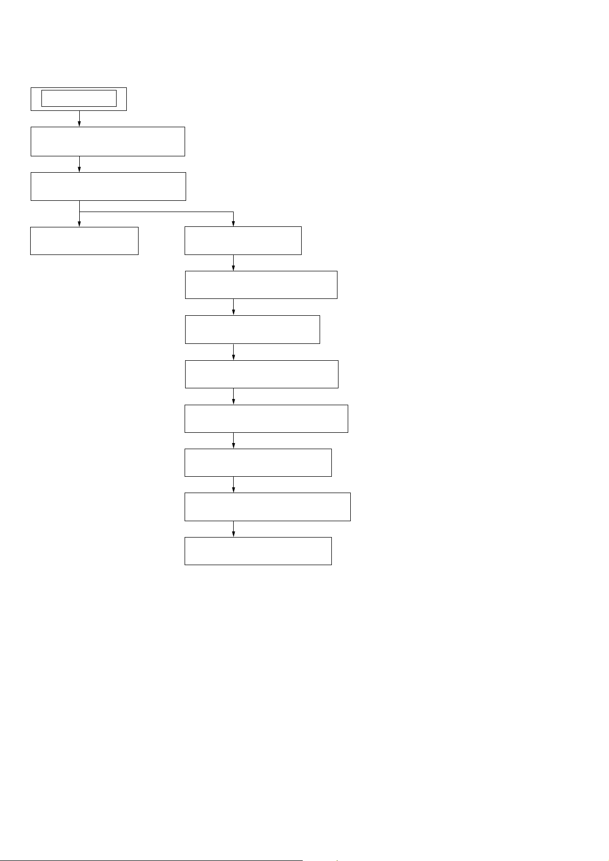
SECTION 2
DISASSEMBLY
Note: This set can be disassemble according to the following sequence.
SET
2-1. SUB PANEL (FL) ASSY
(Page 11)
2-2. CD MECHANISM BLOCK
(Page 11)
2-3. MAIN BOARD
(Page 12)
2-4. SERVO BOARD
(Page 12)
2-5. CHASSIS (T) SUB ASSY
(Page 13)
2-6. ROLLER ARM ASSY
(Page 13)
2-7. CHASSIS (OP) ASSY
(Page 14)
1. CHUCKING ARM SUB ASSY
(SUPPLEMENT-1 Page 1)
2. SLED MOTOR ASSY
(SUPPLEMENT-1 Page 2)
3. OPTICAL PICK-UP SECTION
(SUPPLEMENT-1 Page 3)
10
4. OPTICAL PICK-UP
(SUPPLEMENT-1 Page 3)
Note: Follow the disassembly procedure in the numerical order given.
s
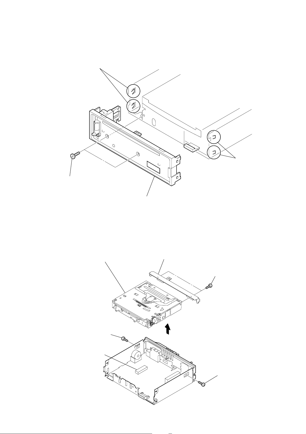
2-1. SUB PANEL (FL) ASSY
3
two claws
CDX-GT317EE/GT360
2
two claw
1
two
screws
(+PTT 2.6
×
6)
2-2. CD MECHANISM BLOCK
7
2
screw
(+PTT 2.6
×
CD mechanism block
6)
4
sub panel (FL) assy
6
bracket (CD)
3
5
two
(+PTT 2.6
screws
×
4)
4
CN350
1
screw
(+PTT 2.6
×
6)
11
CDX-GT317EE/GT360
)
)
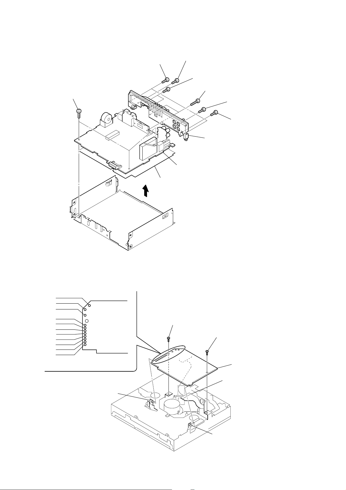
2-3. MAIN BOARD
1
three
screws
(+BTT 2.6
×
2
two
screws
(+PTT 2.6
5)
insulating sheet
3
×
8)
0
5
screw
(+PTT 2.6
4
two
(+P 2.6
6
9
MAIN board
×
10)
screws
×
8)
two
screws
(+PTT 2.6
heat sink
×
7
8
10)
screw
(+P 2.6
screw
(+PTT 2.6
×
10)
×
10
2-4. SERVO BOARD
WHT
RED
BLK
WHT
RED
BLK
RED
ORG
BLE
YEL
GRY
1
Remove the eleven solders.
SERVO board
claw
2
toothed lock
(M 1.7
×
2.5)
screw
3
claw
toothed lock
(M 1.7
4
optical pick-up (16 core
(CN1)
screw
×
2.5)
5
SERVO board
12
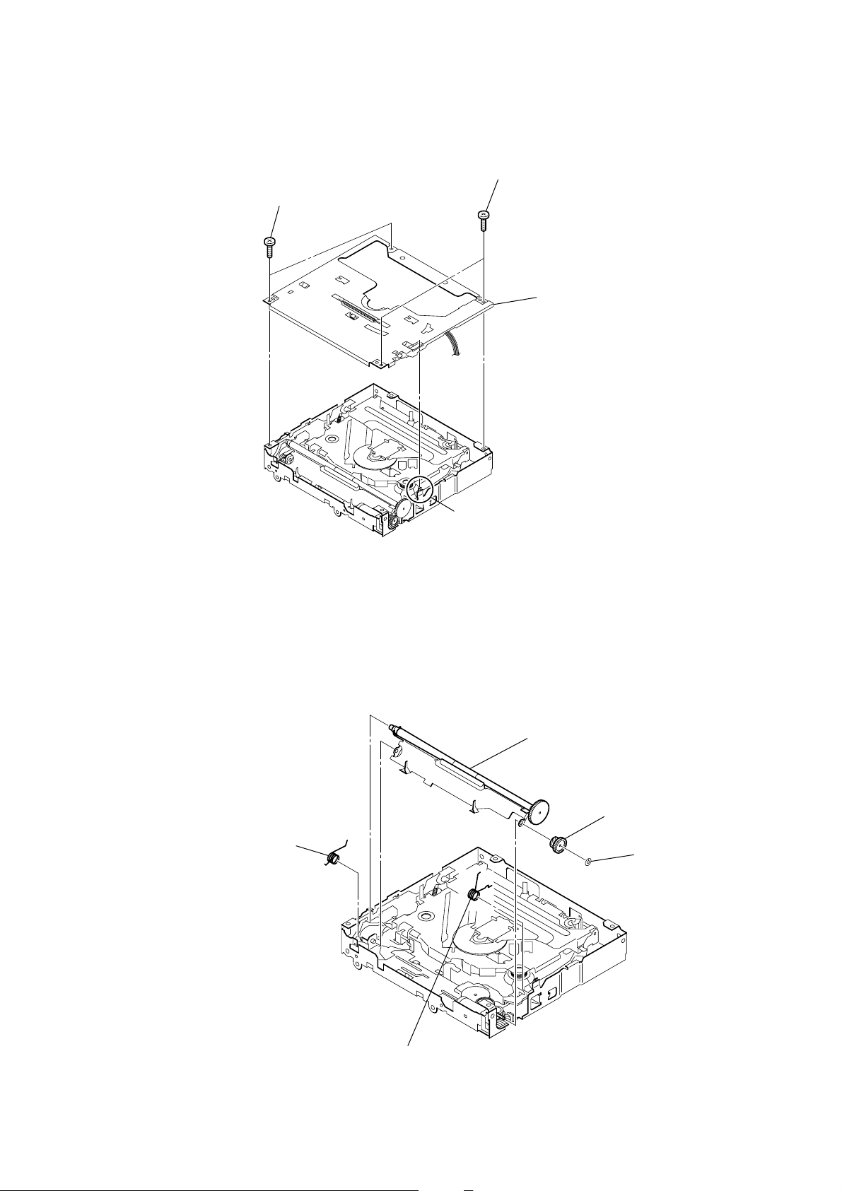
2-5. CHASSIS (T) SUB ASSY
1
two precision
(+P 1.7
×
2.2)
screws
2
two precision
(+P 1.7
4
CDX-GT317EE/GT360
screws
×
2.2)
chassis (T) sub assy
2-6. ROLLER ARM ASSY
1
spring (RAL)
3
claw
5
roller arm assy
4
gear (RA1)
3
washer
2
spring (RAR)
13
CDX-GT317EE/GT360
)
Ver. 1.1
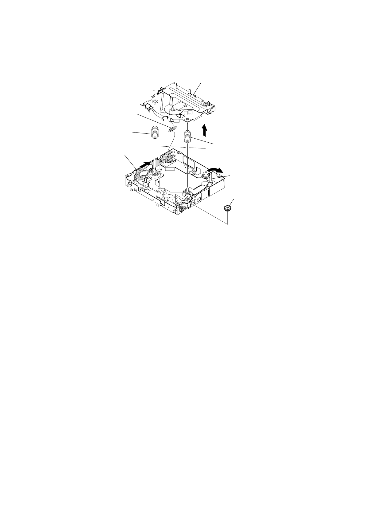
2-7. CHASSIS (OP) ASSY
1
7
coil spring (damper) (natural)
tension spring (KF)
4
slider (R)
6
chassis (OP) assy
5
8
coil spring (damper) (green
3
lever (D)
2
gear (LE1)
14
 Loading...