

SONY CDP-CX53 Service Manual
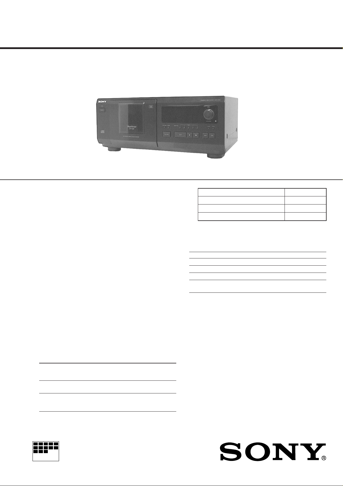
CDP-CX53
SERVICE MANUAL
SPECIFICATIONS
US Model
Canadian Model
AEP Model
E Model
Australian Model
Model Name Using Similar Mechanism CDP-CX50/CX571
CD Mechanism Type CDM-46C2
Base Unit Type
Optical Pick-up Type KSS-213B/S-N
KSM-213BFN/M-NP
Compact disc player
Laser Semiconductor laser (λ = 780 nm)
Emission duration: continuous
Laser output Max 44.6 µW*
* This output is the value measured at
a distance of 200 mm from the
objective lens surface on the
Optical Pick-up block with 7 mm
aperture.
Frequency reponse 2 Hz to 20 kHz ± 1dB
Signal-to-noise ratio More than 100 dB
Dynamic range More than 88 dB
Harmonic distortion Less than 0.013%
Channel separation More than 95 dB
Output
Jack Maximum Load impedance
type output
level
LINE OUT Phono 2V Over 10 kilohms
Jacks (at 50 kilohms)
DIGITAL Optical –18 dBm Wave length: 660 nm
OUT output
(OPTICAL) connector
General
Power requirements
Where purchased Power requirements
USA/Canada 120 V AC, 60 Hz
Australia 240 V AC, 50 Hz
Europe 220 V – 230 V AC, 50/60 Hz
Other countries 110 V – 120 V or 220 V – 240 V AC,
adjustable, 50/60 Hz
Power consumption 12 W
Dimensions (approx.) When the front cover is closed
(w/h/d) 430 × 182.5 × 295 mm (17 × 7 1/4 × 11 5/8 in.)
incl. projecting parts
When the front cover is open
430 × 182.5 × 414 mm (17 × 7 1/4 × 16 3/8 in.)
incl. projecting parts
Mass (approx.) 5.2 kg (11 lbs 8 oz)
Supplied accessories
Audio cord (2 phono plugs – 2 phono plugs) (1)
CONTROL A1 cord (supplied for Canadian models only) (1)
Remote commander (remote) (1)
Sony SUM-3 (NS) batteries (2)
CD booklet holder (1)
Label (1)
Design and specifications are subject to change without notice.
COMPACT DISC PLAYER
MICROFILM
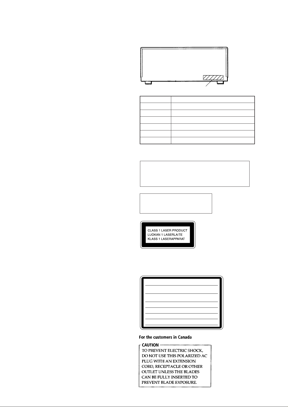
TABLE OF CONTENTS
1. SERVICING NOTE .................................................. 3
2. GENERAL ................................................................... 4
3. DISASSEMBLY ......................................................... 5
4. TEST MODE.............................................................. 9
5. MECHANICAL ADJUSTMENTS ....................... 12
6. ELECTRICAL ADJUSTMENTS......................... 15
7. DIAGRAMS.................................................................17
7-1. Printed Wiring Board – BD Section – ........................... 19
7-2. Schematic Diagram – BD Section – ............................... 21
7-3. Printed Wiring Board – Audio Section –....................... 23
7-4. Schematic Diagram – Audio Section –.......................... 25
7-5. Printed Wiring Boards – Panel Section – ...................... 27
7-6. Schematic Diagram – Panel Section – .......................... 29
7-7. Printed Wiring Board – Sensor/Motor Section – .......... 31
7-8. Schematic Diagram – Sensor/Motor Section – ............. 33
7-9. IC Pin Function Description ........................................... 37
8. EXPLODED VIEWS ................................................ 43
9. ELECTRICAL PARTS LIST ............................... 49
MODEL IDENTIFICATION
— BACK PANEL —
PARTS No.
PARTS No. MODEL
4-997-124-01
4-997-124-11
4-997-124-21
4-997-124-31
4-997-124-41
4-997-124-51
US model
Canadian model
AEP, AED model
Australian model
E model
Singapore model
• Abbreviation
AED: North Europe
CAUTION
Use of controls or adjustments or performance of procedures
other than those specified herein may result in hazardous
radiation exposure.
The laser component in this product
is capable of emitting radiation
exceeding the limit for Class 1.
This appliance is classified as
a CLASS 1 LASER product.
The CLASS 1 LASER
PRODUCT MARKING is
located on the rear exterior.
(Except for the customers in the United States and
Canada)
The following caution label is located inside the unit.
CAUTION :
INTERLOCKS DEFEATED. AVOID EXPOSURE TO BEAM.
ADVARSEL :
SIKKERHEDSAFBRYDERE ER UDE AF FUNKTION. UNDGÅ UDSAETTELSE
FOR STRÅLING.
VORSICHT :
ABDECKUNG GEÖFFNET UND SICHEREITSVERRIEGELUNG
ÜBERBRÜCKT. NICHT DEM STRAHL AUSSETZEN.
VARO!:
TIINA NÄKYMÄTTÖMÄLLE LASERSÄTEILYLLE. ÄLÄ KATSO SÄTEESEEN.
VARNING :
OCH SPÄRREN ÄR URKOPPLAD. BETRAKTA EJ STRÅLEN.
ADVERSEL :
SIKKERHEDSLÅS BRYTES. UNNGÅ EKSPONERING FOR STRÅLEN.
VIGYAZAT!:
GÁRVESZÉLY
INVISIBLE LASER RADIATION WHEN OPEN AND
USYNLIG LASERSTRÅLING VED ÅBNING NÅR
UNSICHTBARE LASERSTRAHLUNG, WENN
AVATTAESSA JA SUOJALUKITUS OHITETTAESSA OLET ALT -
OSYNLING LASERSTRÅLING NÄR DENNA DEL ÄR ÖPPNAD
USYNLIG LASERSTRÅLING NÅR DEKSEL ÅPNES OG
A BURKOLAT NYITÁSAKOR LÁTHATATLAN LÉZERSU-
!
KERÜLJE A BESUGÁRZÁST!
– 2 –
SECTION 1
SERVICING NOTES
SAFETY CHECK-OUT
After correcting the original service problem, perform the following safety check before releasing the set to the customer:
Check the antenna terminals, metal trim, “metallized” knobs,
screws, and all other exposed metal parts for AC leakage.
Check leakage as described below.
LEAKAGE
The AC leakage from any exposed metal part to earth ground and
from all exposed metal parts to any exposed metal part having a
return to chassis, must not exceed 0.5 mA (500 microampers.).
Leakage current can be measured by any one of three methods.
1. A commercial leakage tester, such as the Simpson 229 or RCA
WT -540A. Follo w the manufacturers’ instructions to use these
instruments.
2. A battery-operated AC milliammeter. The Data Precision 245
digital multimeter is suitable for this job.
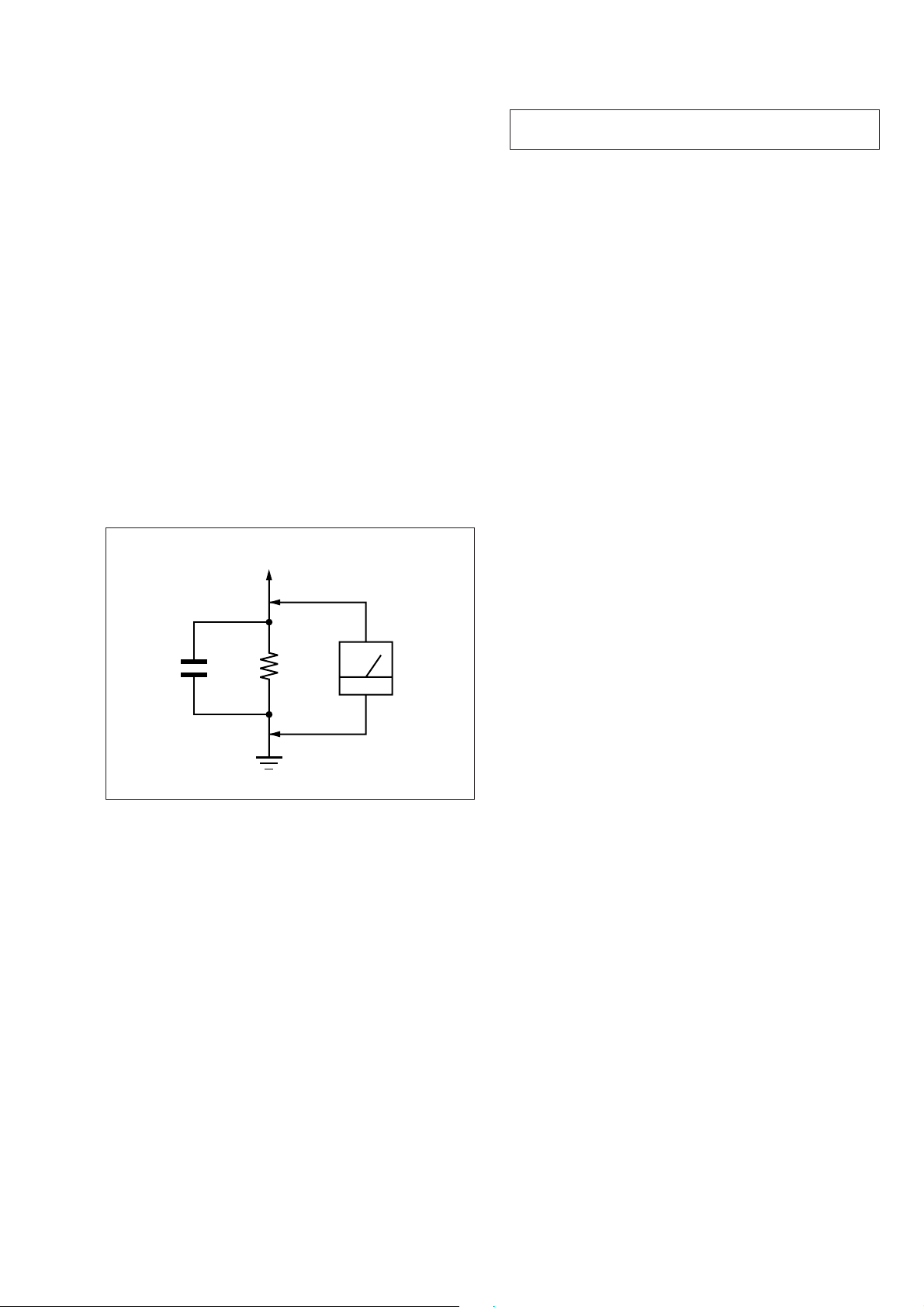
3. Measuring the voltage drop across a resistor by means of a
VOM or battery-operated AC voltmeter. The “limit” indication is 0.75 V, so analog meters must have an accurate lowvoltage scale. The Simpson 250 and Sanwa SH-63Trd are examples of a passive VOM that is suitable. Nearly all battery
operated digital multimeters that have a 2 V A C range are suitable. (See Fig. A)
To Exposed Metal
Parts on Set
NOTES ON HANDLING THE OPTICAL PICK-UP
BLOCK OR BASE UNIT
The laser diode in the optical pick-up block may suffer electrostatic break-down because of the potential difference generated
by the charged electrostatic load, etc. on clothing and the human
body.
During repair, pay attention to electrostatic break-down and also
use the procedure in the printed matter which is included in the
repair parts.
The flexible board is easily damaged and should be handled with
care.
NOTES ON LASER DIODE EMISSION CHECK
The laser beam on this model is concentrated so as to be focused
on the disc reflective surface by the objective lens in the optical
pick-up block. Therefore, when checking the laser diode emission, observe from more than 30 cm away from the objectiv e lens.
LASER DIODE AND FOCUS SEARCH OPERATION
CHECK
Carry out the “S curve check” in ”CD section adjustment” and
check that the S curve waveform is output repeatedly.
1.5 k
0.15 µF
Fig. A. Using an AC voltmeter to check AC leakage.
SAFETY-RELATED COMPONENT WARNING!!
COMPONENTS IDENTIFIED BY MARK ! OR DOTTED
LINE WITH MARK ! ON THE SCHEMATIC DIAGRAMS
AND IN THE PARTS LIST ARE CRITICAL TO SAFE
OPERATION. REPLACE THESE COMPONENTS WITH
SONY PARTS WHOSE PART NUMBERS APPEAR AS
SHOWN IN THIS MANUAL OR IN SUPPLEMENTS PUBLISHED BY SONY.
Ω
Earth Ground
AC
voltmeter
(0.75 V)
ATTENTION AU COMPOSANT AYANT RAPPORT
À LA SÉCURITÉ!
LES COMPOSANTS IDENTIFIÉS P AR UNE MARQUE !
SUR LES DIAGRAMMES SCHÉMATIQUES ET LA LISTE
DES PIÈCES SONT CRITIQUES POUR LA SÉCURITÉ
DE FONCTIONNEMENT. NE REMPLACER CES COMPOSANTS QUE PAR DES PIÈCES SONY DONT LES
NUMÉROS SONT DONNÉS DANS CE MANUEL OU
DANS LES SUPPLÉMENTS PUBLIÉS PAR SONY.
– 3 –
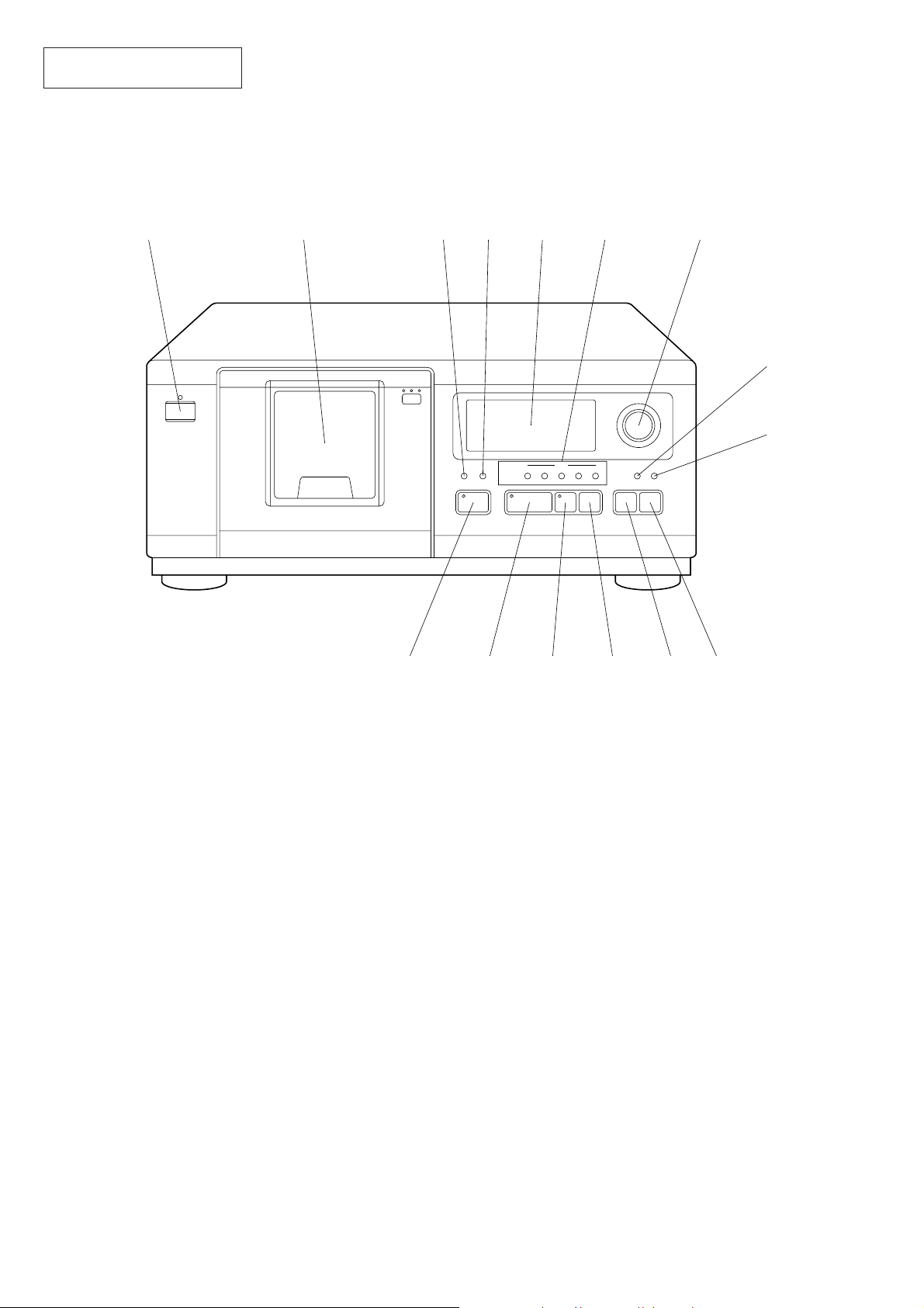
This section is extracted from
instruction manual.
LOCATION OF PARTS AND CONTROLS
Front Panel
SECTION 2
GENERAL
1
STANDBY
I/u
23
PUSH
OPEN
!∞
45 6 7
ª
BLOCK
Pp
PLAY MODE REPEAT BLOCK FILE 1 2 3
PULS ONE
!¢
DISC
PUSH ENTER
4 5 CHECK CLEAR
±
±
8
9
0!¡!™!£
1 I/u (power switch) button
2 Front cover
3 PLAY MODE button
4 REPEAT button
5 Display window
6 BLOCK 1-5 buttons
7 DISC PUSH ENTER knob
8 CHECK button
9 CLEAR button
!º ± button
!¡ ≠ button
!™ p button
!£ P button
!¢ · button
!∞ PLUS ONE button
– 4 –
SECTION 3
)
DISASSEMBLY
Note: Follow the disassembly procedure in the numerical order given.
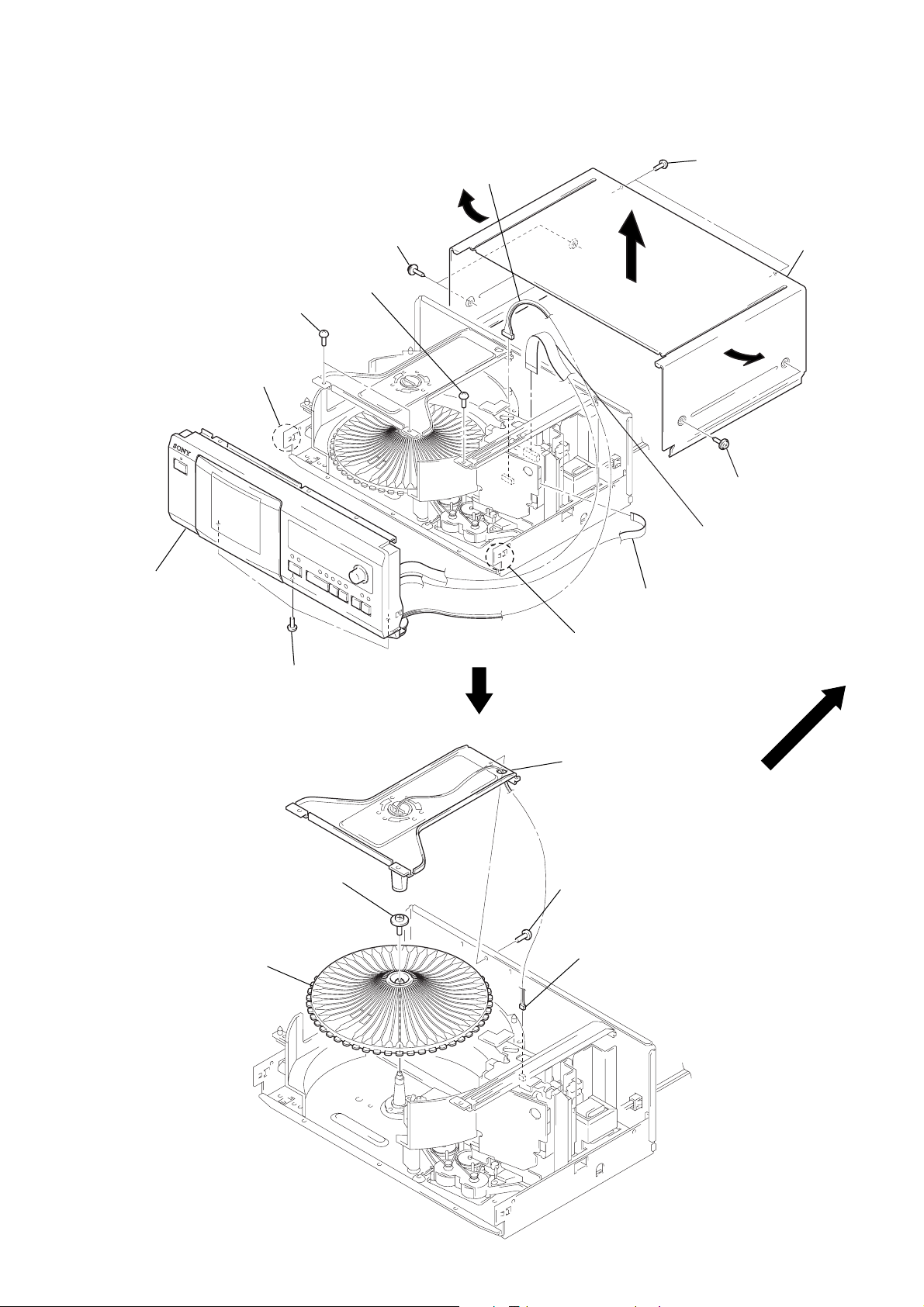
CASE, FRONT PANEL
3
two screws
(BVTT3 × 6)
9
claw
0
front panel
1
two screws
(M3 × 8)
4
screw
(BVTT3 × 6)
5
connector
(CN803)
1
two screws
(M3 × 8)
6
wire (flat type) (15 core
(CN801)
7
wire (flat type) (9 core)
(CN103)
1
two screws
(M3 × 8)
2
case
TABLE (50)
5
table (50)
4
screw
(PTPWH2.6
8
three screws
(BVTT3 × 6)
×
8)
9
claw
3
bracket
(ILLUMINATION)
1
screw
(BVTT3
2
connector
(CN84)
×
6)
– 5 –
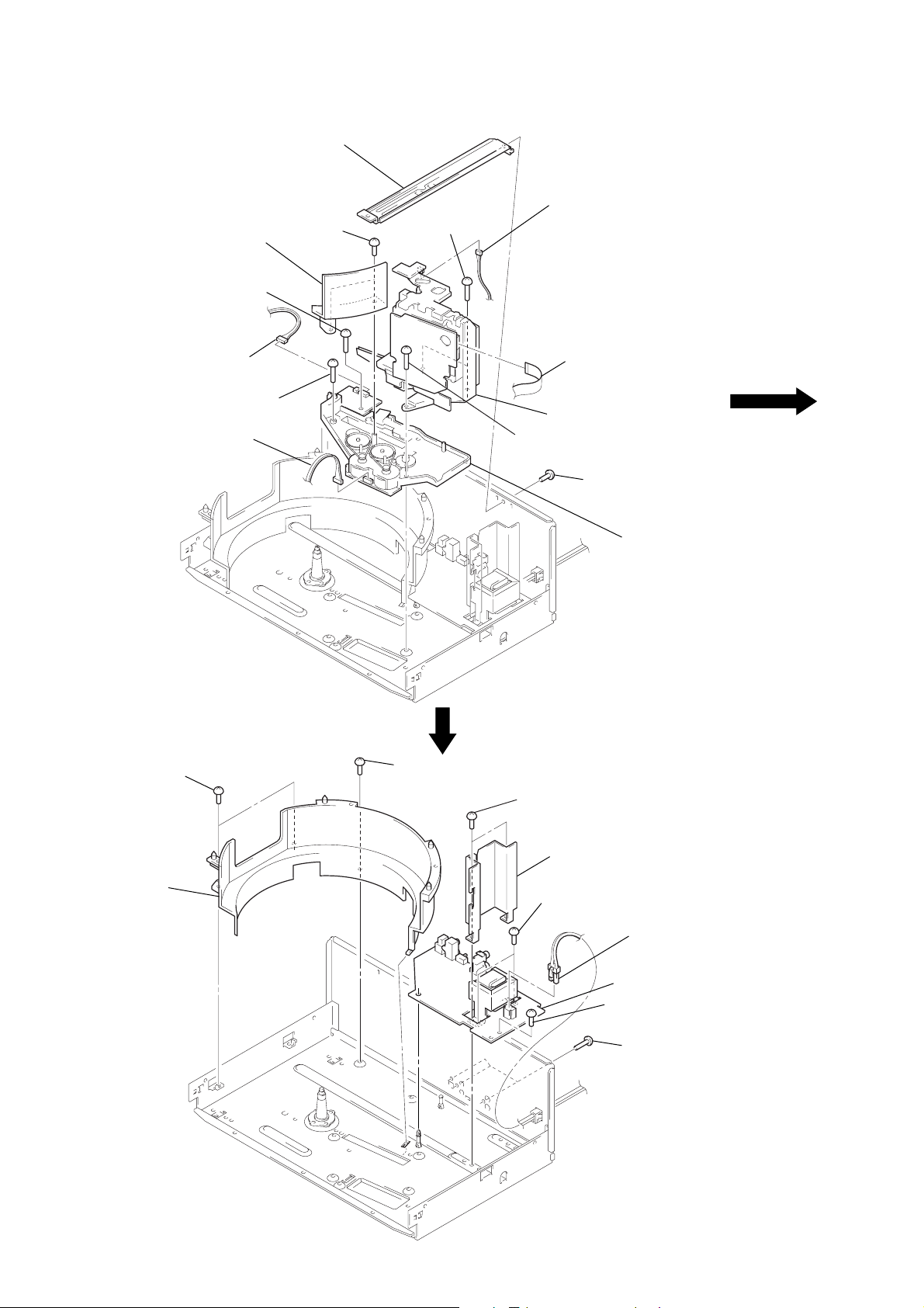
CD MECHANISM DECK SECTION
3
two screws
×
14)
screw
(BVTT3
(BVTP3
9
0
!¡
connector
(CN61)
4
ring (B)
screw
(P3
connector
(CN51)
9
2
reinforcement
×
×
8)
8)
5
two screws
(BVTT3
×
10)
5
6
connector
(CN53)
7
8
base (LOADING)
screw
(BVTT3
×
wire (flat type) (12 core)
(CN102)
6)
1
screw
×
(BVTT3
6)
!™
base (CDM)
AUDIO BOARD
1
two screws
2
ring (A)
1
screw
(BVTP3 × 8)
3
two screws
(BVTT3 × 6)
4
6
two screws
(BVTT3 × 6)
transformer cover
8
connector
(CN701)
9
AUDIO board
5
screw
(BVTT3 × 6)
7
three screws
(BVTP3 × 10)
– 6 –
BASE UNIT
)
2
bracket
1
two screws
(BTP2.6
3
×
8)
screw
(BTP2.6
×
10)
4
reinforcement (small)
5
two tention springs
7
base unit
6
four screws
(PTPWH2.6
×
8
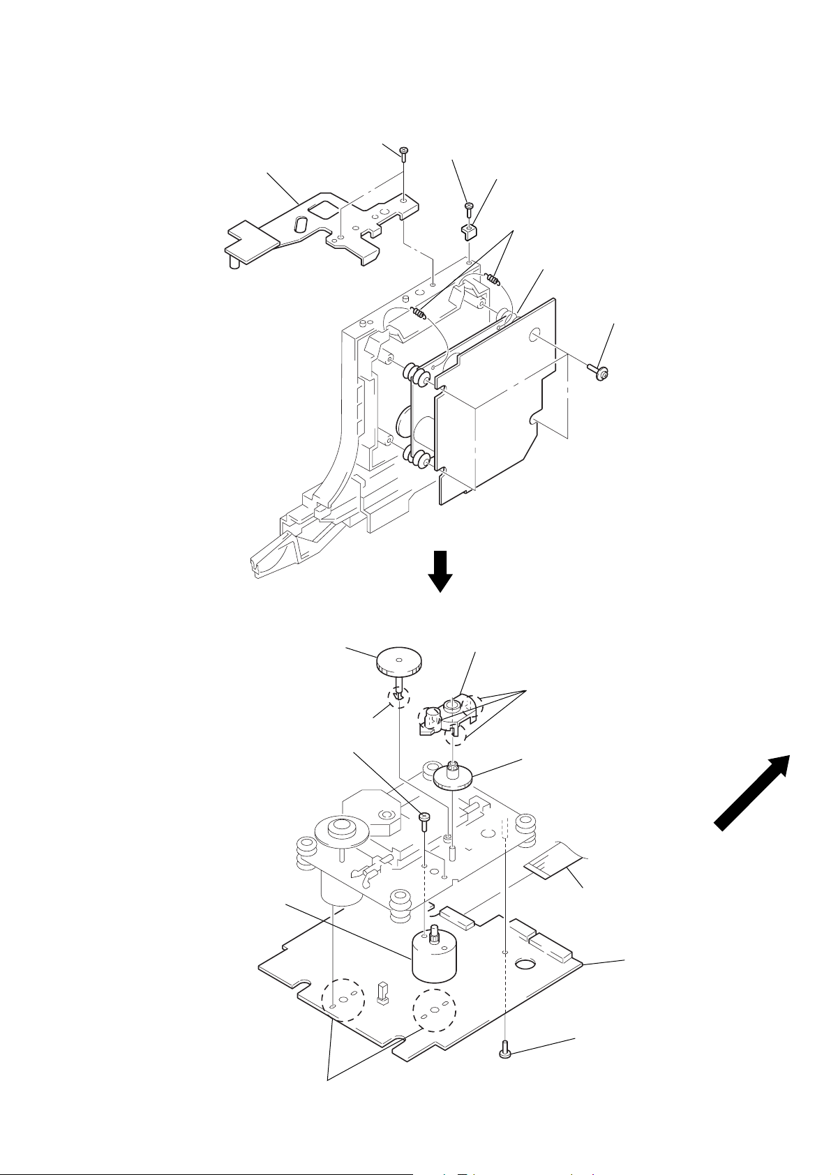
BD BOARD, SLED MOTOR (M102)
6
gear (A) (S)
0
two screws
(2 × 3)
!¡
sled motor
(M102)
5
claw
8
gear cover
7
three claws
9
gear (B) (RP)
1
wire (flat type) (16 core)
(CN101)
4
BD board
3
Removal
four solders.
– 7 –
2
screw
(B2 × 5)
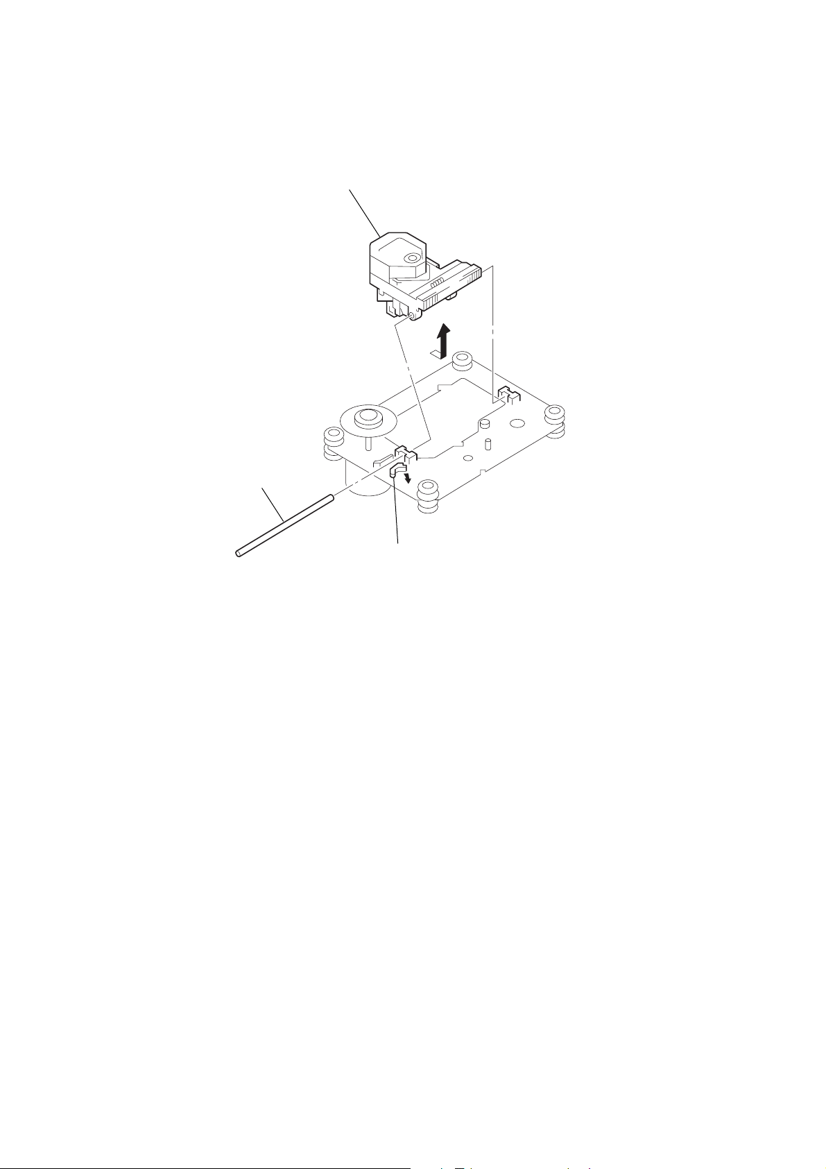
OPTICAL PICK-UP (KSS-213B/S-N)
3
Remove the optical
pick-up to direction
of the arrow A.
2
sled shaft
A
1
claw
– 8 –
SECTION 4
TEST MODE
DISPLAY CHECK MODE
Note:
This will not work properly if the DISC is set to any slit.
1. Press the I/u button, turn ON the power, and set a CD in any
slit.
2. Press the I/u button, and turn OFF the power.
3. While pressing the [CHECK] and [PLUSONE] buttons together with the power OFF , press the I/
u button and turn ON
the power.
4. All the segments of the fluorescent indicator tube light up, and
the · , P , and [PLUSONE] LEDs light up.
5. To exit the display check mode, press the I/u button.
ADJ MODE
1. Press the I/u button to turn the power ON.
2. Open the front cover, and press the [PLUSONE] button.
3. Set the disc (YEDS-18 : 3-702-101-01) in the PLUS ONE slit.
4. Close the front cover, and chuck the disc.
5. Press the I/
6. Connect TP (ADJ) of the DISPLA Y board and the ground with
a lead wire.
7. Press the I/u button and turn ON the power.
The ADJ mode is set with the above.
u button, and turn OFF the power.
FLUORESCENT INDICATOR TUBE, LED ALL LIT,
AND KEY CHECK MODE
Connect TP (AFADJ) and ground of the DISPLAY board with a
lead wire.
When a button is pressed, the left side of the indicator tube will
show how many buttons have been pressed so far.
(However, buttons already pressed once will not be counted.)
The right side will show the numbers corresponding to the pressed
buttons.
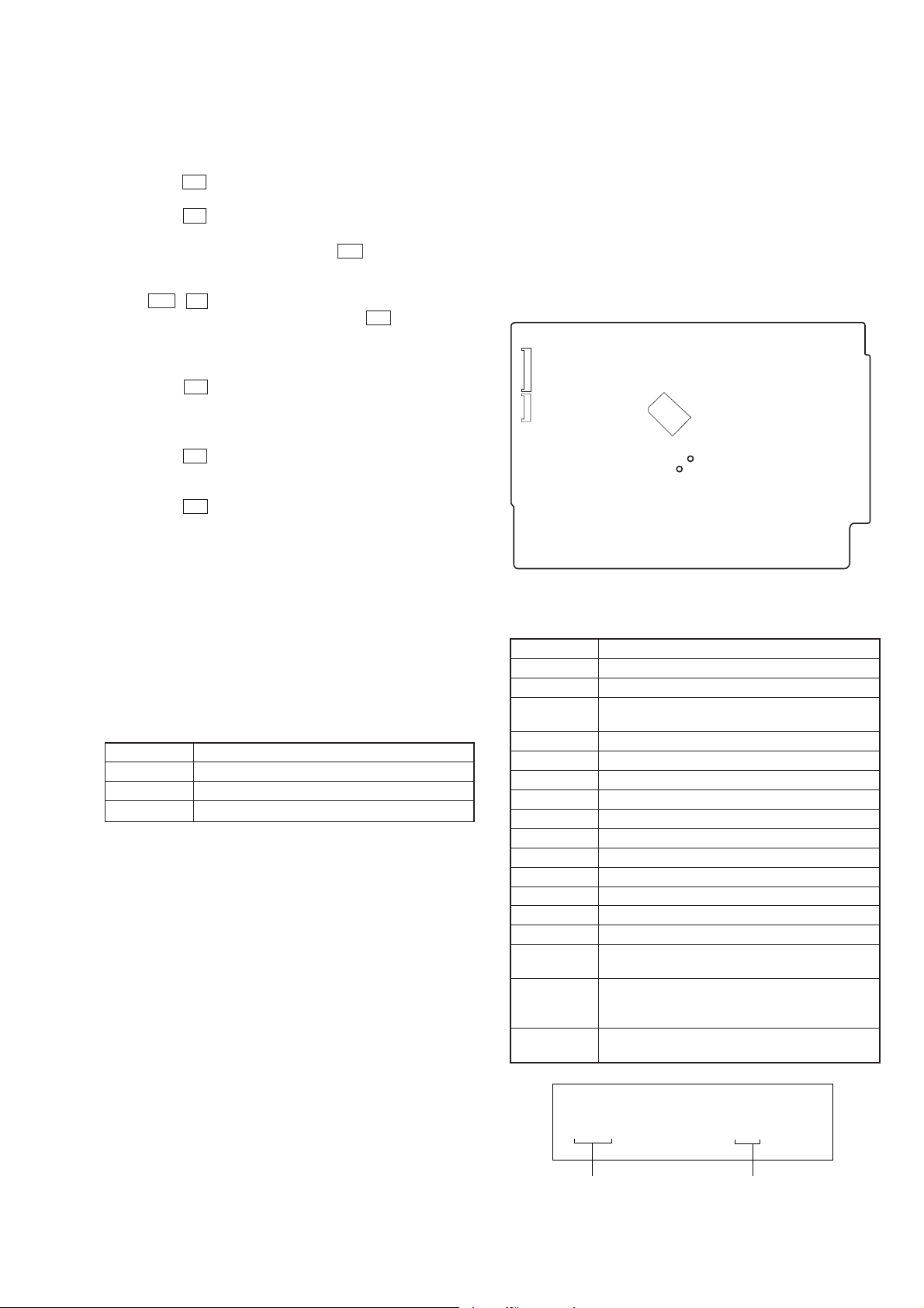
[ DISPLAY BOARD ] — CONDUCTOR SIDE —
CNP801
IC801
CNP804
TP(AFADJ)
TP(ADJ)
Differences with normal mode
• No high speed search is performed during access
• Ignored even if GFS becomes L
• Ignored even if Q data cannot be read
• Spindle servo gain is set to 12 cm mode (Even with 8 cm disc)
The following special functions will work when certain functions
are pressed in this mode.
Special functions in ADJ mode
(The ( ) buttons function only with the general purpose remote.)
Button Function
(3) Tracking servo, sled servo OFF
(8) Tracking servo, sled servo ON
CHECK S shape observation mode
Buttons and Corresponding Button Numbers
Button Button Number or Display
CLEAR 0
CHECK 1
DISC
PUSH ENTER
± 8
≠ 9
REPEAT 14
PLAY MODE 15
BLOCK 5 16
BLOCK 4 17
BLOCK 3 18
BLOCK 2 19
BLOCK 1 20
I/u 21
PLUS ONE While the button is pressed, LED (D803) lights up.
·
P is partially lit and LED near by (D802) is lit while
p
2
While the button is pressed, LED (D801) lights, and
the whole fluorescent indicator tube lights up.
The fluorescent indicator tube (segment check)
pressed.
The fluorescent indicator tube is partially lit while
pressed (grid check).
– 9 –
1 DISC
**
Count up
**
CD 1
Button number
2
1. Grid check
(
)
1 DISC
88
2. Segment check
Key Inputs Other than Buttons and How to Display
Key input Display
Rotate the JOG knob to
the right
Rotate the JOG knob to
the left
Press the JOG knob
(ENTER)
Door cover “Close” [STANDBY] LED goes OFF
Door cover “Open” [STANDBY] LED lights up
88
CD 1
Fluorescent indicator tube block indicator
lights up in the order of 1 n 2 n 3 n 4 n
5 n 1 n ·····.
Fluorescent indicator tube block indicator
lights up in the order of 5 n 4 n 3 n 2 n
1n 5 n ·····.
Displays button number 2
88
7
---
onn
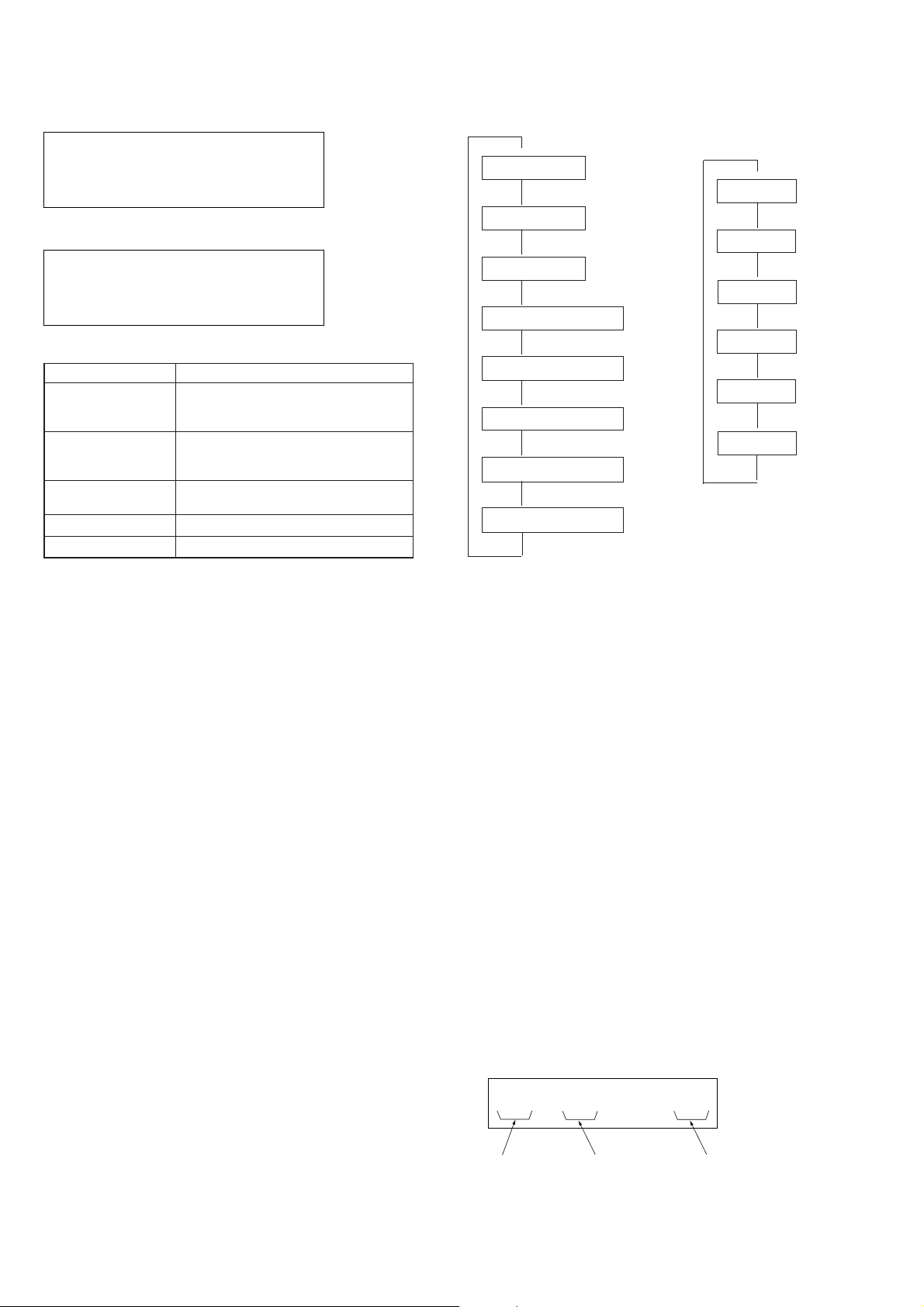
Sequence of Aging Mode
$
1. Disc change
$
2. Load in
$
3. TOC read
$
4. Access of last track
$
5. 3 second playback
$
6. Access of first track
$
7. 3 second playback
$
8. Load out
$
Order of Disc Change
(1 cycle takes 3 minutes)
$
1. No. 51
$
2. No. 20
$
3. No. 40
$
4. No. 30
$
5. No. 10
$
6. No. 40*
$
AGING MODE
• Mode which repeatedly changes and plays back discs automatically in the unit.
• It will repeat aging as long as no errors occur.
• If an error occurs during aging, it will stop all servos, motors,
etc. instantaneously, display the error number, and stop operations. However, the stopping conditions differ according to
whether the unit is equipped with the “self-protection function
during errors” described later.
The function serves to maintain the state of the unit when errors
occur.
* DISC No. 40 chucks twice during one cycle.
T o dif ferentiate, the “[2]” on the block indicator of the fluorescent indicator tube will light up during the second chucking.
Special Functions in Aging Mode
There are some useful function in the aging mode.
• Disc setting mode*1
• Switching of use/disuse of protection function in errors *2
• Aging cycle count function *3
*1 Disc setting mode:
5 discs are set before setting the aging mode. This mode makes
the setting of these discs more easy.
*2 Switching of use/disuse of protection function in errors:
Function which voluntarily corrects errors which occur during normal operations by retries.
If this function is not provided, all operations will be stopped
without retiring. It is suitable for checking errors with low reproducibility.
If this function is provided, and errors can be corrected by
retries, aging will be continued without stopping.
(The normal aging should be performed with “be”.)
*3 Aging cycle count function:
Functions which displays the number of agings carried out on
the Fluorescent indicator tube in numbers. One aging cycle
consists of six discs.
DISC
51
Disc number Track number Agings carrried
TRACK1MIN SEC
0.01
*
1 n 2 n 3 n .....
– 10 –
Aging procedure:
(
Some operating method will be changed depending on if the following jig for the aging mode exists or not.
• Jig
Parts. No Description
J-2501-123-A Remote commander (For aging mode)
With remote commander for aging mode:
1. Turn ON the power of the unit. Open the front cover.
2. Press the [AGINGSTART] button of the remote commander
for aging mode.
3. When the disc set mode is set, the · and P LEDs blink.
4. Rotate the JOG dial. The slits (No. 10, 20, 30, 40, 51) for set-
ting the discs will come forward. Insert the discs into these
slits. Do not set the discs in other slits.
5. Set the use/disuse of the self protection function in errors. Press
the
[REPEAT] button. When REPEAT is displayed on the fluo-
rescent indicator tube, the self protection function during the
error will become “Use”.
If the REPEAT displa y is OFF, it means that the function is
not used. (Normally set to “Use” when performing aging.)
6. Press the · button.
7. The · LED blinks, the aging mode is set, and aging is
started.
8. The aging cycle lasts 3 minutes. When problems occur during
aging, the error number will be displayed on the fluorescent
indicator tube, and the P LED will light up.
(Refer to the following table for the details of the errors.)
9. Aging will be repeated as long as no errors occur.
10. After each ag ing cycle, the number displayed on the Fluores-
cent indicator tube will increase.
11. To end aging, press the I/u button
Without remote commander for aging mode:
1. Turn ON the power of the unit. Open the front cover.
2. Press the [PLAYMODE], · , and ≠ buttons in order.
3. When the disc set mode is set, the · and P LEDs blink.
The following procedure is the same as in the case “With remote
commander for aging mode”.
Error Display
DISC
51
Disc number
26
Error code number of agings
Err
*
1 n 2 n 3 n.....)
Error code
Code number Name Contents
Err 01 DISC sensor check 1 No disc in the specified slit
Err 02 DISC sensor check 2 Disc in other slits
Err 03 No function
Err 04 Table operation check 2 No table sensor input
Err 05 Loading operation check 1 Load in timeover
Err 06 Loading operation check 2 Load out timeover
Err *1 BU related check 1 Access timeover
Err *2 BU related check 2 High speed search NG
Err *3 BU related check 3 Q data read error
Err *4 BU related check 4 BU operation (From focus search to until signal can be read) timeover
Err *5 BU related check 5 GFS monitor error
Err *6 BU related check 6 Focus cannot be imposed by focus search
The * numbers mean the following according to the state of the unit during aging
2 : From checking to end of TOC read
3 : From end of TOC read to end of last track playback
4 : From end of last track playback to end of first track playback
– 11 –
SECTION 5
MECHANICAL ADJUSTMENTS
To adjust the mechanism section, enter the mechanism section adjustment mode.
For how to enter the mechanism section adjustment mode, refer to each adjustment section.
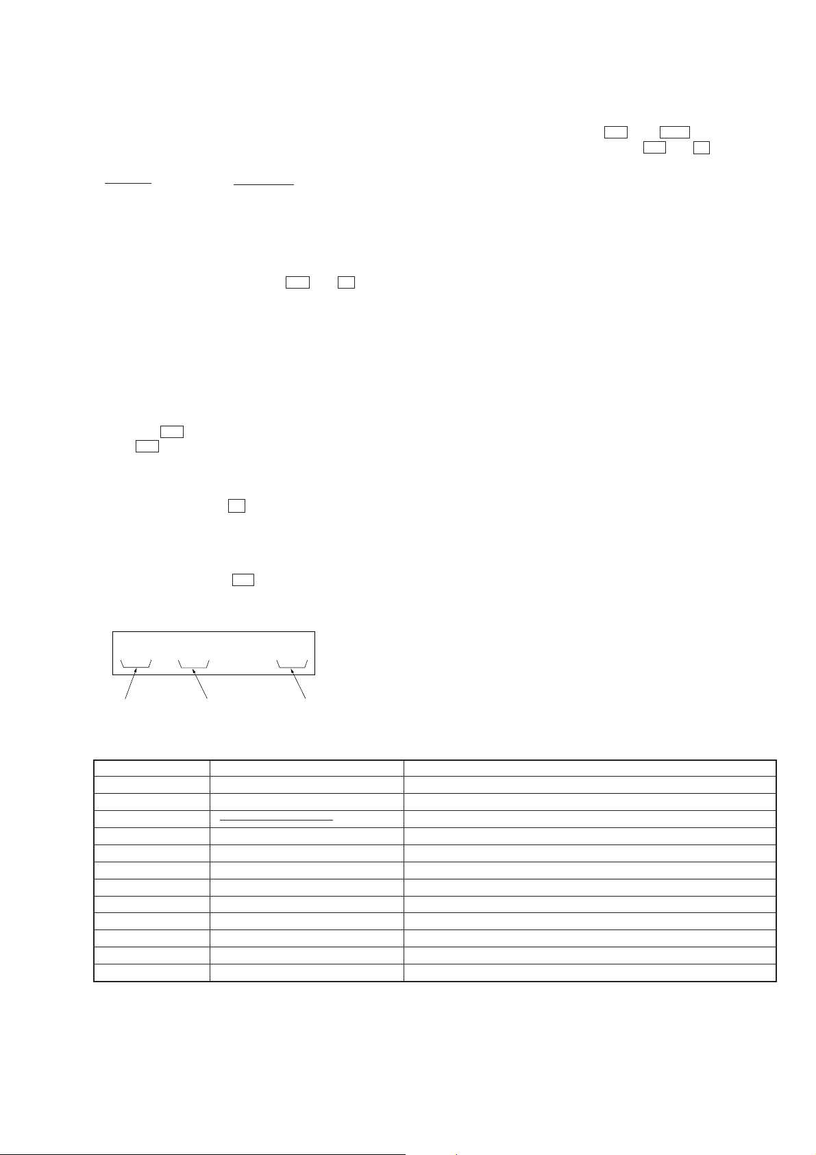
DISC SENSOR ALIGMENT
1. Make sure that there is no disc in the unit.
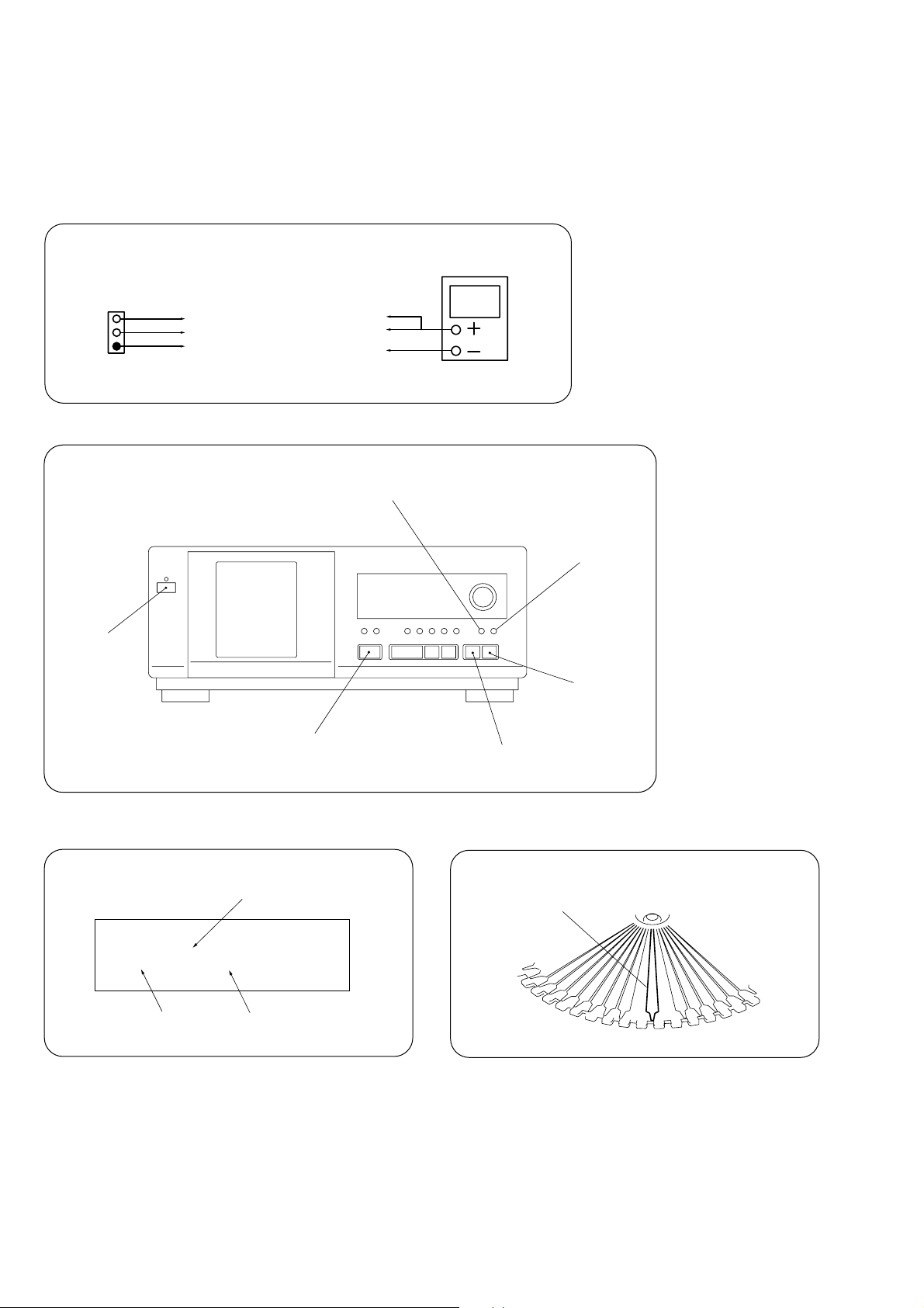
2. Connect an oscilloscope to TP501 of the AUDIO board.
oscilloscope
SENS
GND
TEST
AUDIO board
TP501
SENS (CH1)
TEST (CH2)
GND
3. While pressing the [CLEAR] and [PLUSONE] buttons at the same time and turn ON the power.
CHECK button
CLEAR button
POWER switch
±
button
PLUS ONE button
≠
button
4. The fluorescent indicator tube shows as follows, and the mechanism section adjustment mode is set.
ALL DISCS
DISC
* *
DISC No.
Lit according to rotational direction
SEC
3.6
11111
CD1
Rotation time
PLUS ONE
5. The disc table rotates in the clockwise direction. The disc table rotation time is displayed with “PLUS ONE” slit as a measuring point.
6. Measure the waveform of the oscilloscope when the disc table is rotating.
– 12 –
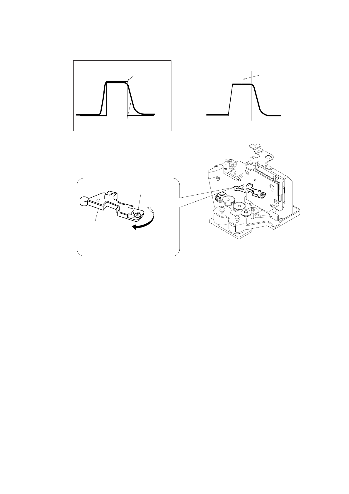
7. Move the holder (sensor) center so that the flat portion center at the top of the SENS (CH1) input waveform and the ‘’H” center of
TEST (CH2) coincide.
SENS (CH1) waveform
Holder (sensor)
TEST (CH2) waveform
Fixed screw
Flat portion center of
SENS (CH1) waveform
8. Tighten the fixed screw to fix the disc table, then press the [CLEAR] button.
9. The disc table rotates in the counterclockwise direction. Measure the waveform and make sure that the flat portion center at the top of
the SENS (CH1) input waveform and the ‘’H” center of TEST (CH2) coincide.
10. If the adjustment is not successful, press the
[CLEAR] button to rotate the disc table in the clockwise direction,
and perform steps 6 to 9.
Note: During the adjustment mode, the rotational direction is switched each time the [CLEAR] button is pressed.
Pressing the [CHECK] button enters the loading mode which will be described later. Pressing the [CLEAR] button rotates the disc table again.
– 13 –
MAGNET ASSY ALIGMENT
)
)
1. Check that there is no disc in the unit and then turn ON the power. Open the door, and set a disc in the PLUS ONE slit.
2. Turn OFF the power, close the door, and while pressing the [CLEAR] and [PLUSONE] buttons simultaneously, turn ON the power
again.
3. Press the
[CHECK] button, and set the loading mode.
4. Press the ± button and chuck the disc.
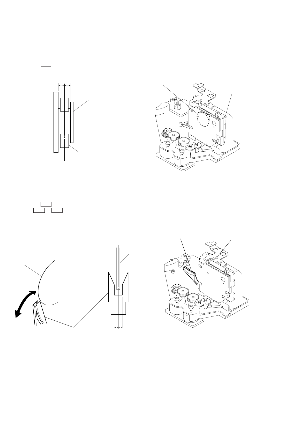
5. Adjust the magnet assembly and magnet holder so that A=B as shown in the figure.
A B
Magnet ASSY
Magnet holder
Magnet ASSY
Screw (For adjustment
DISC HOLDER A ALIGMENT
1. Check that there is no disc in the unit and then turn ON the power. Open the door, and set a disc in the PLUS ONE slit.
2. Turn OFF the power, close the door , and while pressing the [CLEAR] and [PLUSONE] buttons simultaneously, turn ON the power
again.
3. Press the
4. Press the ± button and chuck the disc.
5. Press ≠ or ± button to stop the disc holder A slightly away from the disc.
6. Rotate and adjust the adjusting screw so that the center of the disc and that of the disc holder coincide.
[CHECK] button, and set the loading mode.
Disc
Disc holder A
a b
a = b
Disc
Disc holder A
Screw (For adjustment
– 14 –
SECTION 6
level : 1.6
±
0.3
Vp-p
0.2
VOLT/DIV : 200mV
TIME/DIV : 500ns
RF signal waveform
)
)
ELECTRICAL ADJUSTMENTS
Note :
1. CD Block is basically designed to operate without adjustment.
Therefore, check each item in order given.
2. Use YEDS-18 disc (3-702-101-01) unless otherwise indicated .
3. Use an oscilloscope with more than 10MΩ impedance.
4. Clean the object lens by an applicator with neutral detergent
when the signal level is low than specified value with the following checks.
S Curve Check
oscilloscope
BD board
TP (FE)
TP (VC)
+
–
Procedure :
1. Press the I/u button and turn ON the power supply.
2. Open the front cover, and press the [PLUSONE] button.
3. Set the disc (YEDS-18) into the “PLUS ONE” slit.
4. Close the front cover, and chuck the disc.
5. Press the I/
u button and turn OFF the power.
6. Connect the oscilloscope to TP (FE) of the BD board.
7. Connect TP (ADJ) of the DISPLA Y board and the ground with
a lead wire.
8. Press the I/u button and turn ON the power.
9. The first track will be played back automatically. When the
[CHECK] button is pressed, “S JI” will be displayed on the
fluorescent indicator tube, and focus search will be repeated.
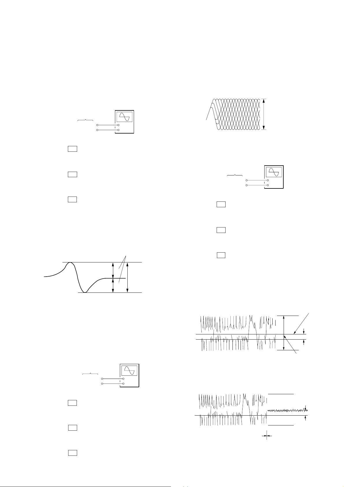
10. Check the oscilloscope waveform (S-curve) is symmetrical between A and B. And confirm peak to peak level within 1.8 ±
0.6 Vp-p.
S-curve waveforms
symmetry
A
within 1.8
B
11. Turn OFF the power, and remove the lead wire connected at
step 7.
Note: • Try to measure several times to make sure than the ratio of A : B
or B : A is more than 10 : 7.
• Take sweep time as long as possible and light up the brightness
to obtain best waveform.
RF Level Check
oscilloscope
(AC range)
BD board
TP (RF)
TP (VC)
+
–
±
0.6Vp-p
10. Confirm that oscilloscope waveform is clear and check RF signal level is correct or not.
11. Turn OFF the power, and remove the lead wire connected at
step 7.
Note: A clear RF signal wav eform means that the shape “◊” can be clearly
distinguished at the center of the waveform.
E-F Balance (Traverse) Check
The procedure for this checking method differs for when a general
remote control unit is used and not used.
oscilloscope
BD board
TP (TE)
TP (VC)
+
–
When a general remote commander is used:
1. Press the I/u button and turn ON the power supply.
2. Open the front cover, and press the [PLUSONE] button.
3. Set the disc (YEDS-18) into the “PLUS ONE” slit.
4. Close the front cover, and chuck the disc.
5. Press the I/
u button and turn OFF the power.
6. Connect the oscilloscope to TP (TE) of the BD board.
7. Connect TP (ADJ) of the DISPLAY board and the g round with
a lead wire.
8. Press the I/u button and turn ON the power.
9. Playback the fifth track of the disc.
10. Press the [3] button on the remote commander. (The tracking
servo and the sledding servo are turned OFF.)
11. Check the level B of the oscilliscope's wa veform and the A (DC
voltage) of the center of the Traverse waveform.
Confirm the following :
A/B x 100 = less than ± 10%
Traverse waveform
0 V
12. Press the
[8] button on the remote control unit. (The tracking
Center of the waveform
B
A (DC voltage
level : 1.3
±
0.5 Vp-p
servo and sledding servo are turned ON.) Confirm the C (DC
voltage) is almost equal to the A (DC voltage) is step 11.
Traverse waveform
Procedure :
1. Press the I/u button and turn ON the power supply.
2. Open the front cover, and press the [PLUSONE] button.
3. Set the disc (YEDS-18) into the “PLUS ONE” slit.
4. Close the front cover, and chuck the disc.
5. Press the I/u button and turn OFF the power.
6. Connect the oscilloscope to TP (RF) of the BD board.
7. Connect TP (ADJ) of the DISPLA Y board and the ground with
a lead wire.
8. Press the I/u button and turn ON the power.
9. Playback the fifth track of the disc.
0 V
Tracking servo
Sled servo
OFF
Tracking servo
Sled servo
ON
13. Turn OFF the power, and remove the lead wire connected at
step 7.
– 15 –
C (DC
voltage
 Loading...