


Sony BTA-NW1 User Manual
3-070-124-11 (2)
Modem Adaptor
with Bluetooth
™
Function
Operating Instructions
Before operating the unit, please read this manual thoroughly, and retain
it for future reference.
Owner’s Record
The model and serial numbers are located on the bottom. Record the serial
number in the space provided below. Refer to these numbers whenever
you call upon your Sony dealer regarding this product.
Model No. BTA-NW1
Serial No.
Mode d’emploi
GB
FR
BTA-NW1
© 2001 Sony Corporation

WARNING
To prevent fire or shock hazard, do not expose the unit to rain or moisture.
Countries and areas
This product is intended to be used in the following countries or areas.
Australia, Austria, Belgium, Canada, Denmark, Finland, France, Germany, Greece,
Hong Kong, Ireland, Japan, Luxembourg, Netherlands, New Zealand, Norway,
Portugal, Singapore, Sweden, Switzerland, UK, USA
This product is intended to be in indoor use only in Canada and France.
Regulatory Information
For the Customers in the USA
CAUTION
You are cautioned that any changes or modifications not expressly approved in this
manual could void your authority to operate this equipment.
To comply with FCC RF exposure compliance requirements, a separation distance of at
least 20 cm must be maintained between enclosure of this equipment and all persons.
NOTE:
This equipment has been tested and found to comply with the limits for a Class B
digital device, pursuant to Part 15 of the FCC Rules. These limits are designed to
provide reasonable protection against harmful interference in a residential installation.
This equipment generates, uses, and can radiate radio frequency energy and, if not
installed and used in accordance with the instructions, may cause harmful interference
to radio communications.
However, there is no guarantee that interference will not occur in a particular
installation. If this equipment does cause harmful interference to radio or television
reception, which can be determined by turning the equipment off and on, the user is
encouraged to try to correct the interference by one or more of the following measures:
— Reorient or relocate the receiving antenna.
— Increase the separation between the equipment and receiver.
— Connect the equipment into an outlet on a circuit different from that to which the
receiver is connected.
— Consult the dealer or an experienced radio/TV technician for help.
2-GB
FCC Part 68
This equipment (MDM-5614G exclusive modem card) complies with Part 68 of the FCC
rules. On the bottom of this equipment is a label that contains among other information,
the FCC equivalence number (REN) for this equipment. If requested, this information
must be provided to the telephone company.
This modem uses the USOC RJ-11 telephone jack.

The REN is used to determine the quantity of devices which may be connected to the
telephone line. Excessive RENs on the telephone line may result in the devices not
ringing in response to an incoming call. In most, but not all areas, the sum of the RENs
should not exceed five (5.0). To be certain of the number of devices that may be
connected to the line, as determined by the total RENs, contact the telephone company
to determine the maximum REN for the calling area.
If the terminal equipment (
telephone network, the telephone company will notify you in advance that temporary
discontinuance of service may be required. But if advance notice isn’t practical, the
telephone company will notify the customer as soon as possible. Also, you will be
advised of your right to file a complaint with the FCC if you believe it is necessary.
The telephone company may make changes in its facilities, equipment, operations or
procedures that could affect the operations of the equipment. If this happens, the
telephone company will provide advance notice in order for you to make the necessary
modifications in order to maintain uninterrupted service.
If trouble is experienced with this equipment (MDM-5614G exclusive modem card),
please contact 1-800-222-SONY (7669), or write to the Sony Customer Information
Service Center, 12451 Gateway Blvd., Fort Myers, Fl 33913 for repair and (or) warranty
information. If the trouble is causing harm to the telephone network, the telephone
company may request you remove the equipment from the network until the problem
is resolved.
Repair of this equipment should be made only by a Sony Service Center or Sony
authorized agent. For the Sony Service Center nearest you, call 1-800-222-SONY (7669).
This equipment cannot be used on public coin service provided by the telephone
company. Connection to Party Line Service is subject to state and possible provincial
tariffs. (Contact the state or provincial utility service commission, public service
commission or corporation commission for information.)
MDM-5614G exclusive modem card
For the Customers in CANADA
Operating Condition
Operation is subject to the following two conditions: (1) this device may not cause
interference, and (2) this device must accept any interference, including interference
that may cause undesired operation of the device.
) causes harm to the
To prevent radio interference to the licensed service, this device is intended to be
operated indoors and away from windows to provide maximum shielding. Equipment
(or its transmit antenna) that is installed outdoors is subject to licensing.
INDUSTRY CANADA NOTICE
NOTICE: The Industry Canada label identifies certified equipment. This certification
means that the equipment meets certain telecommunications network protective,
operational and safety requirements as prescribed in the appropriate Terminal
Equipment Technical Requirements document(s). The Department does not guarantee
the equipment will operate to the user’s satisfaction.
Before installing this equipment, users should ensure that it is permissible to be
connected to the facilities of the local telecommunications company. The equipment
must also be installed using an acceptable method of connection.
3-GB

The customer should be aware that compliance with the above conditions may not
prevent degradation of service in some situations.
Repairs to certified equipment should be coordinated by a representative designated by
the supplier. Any repairs or alterations made by the user to this equipment, or
equipment malfunctions, may give the telecommunications company cause to request
the user to disconnect the equipment.
Users should ensure for their own protection that the electrical ground connections of
the power utility, telephone lines and internal metallic water pipe system, if present, are
connected together. This precaution may be particularly important in rural areas.
Caution: Users should not attempt to make such connections themselves, but should
contact the appropriate electric inspection authority, or electrician, as appropriate.
NOTICE: The Ringer Equivalence Number (REN) assigned to each terminal device
provides an indication of the maximum number of terminals allowed to be connected to
a telephone interface. The termination on an interface may consist of any combination
of devices subject only to the requirement that the sum of the Ringer Equivalence
Number of all the devices does not exceed 5. The Ringer Equivalence Number for this
equipment is 0.1.
For the Customers in Europe
Hereby, Sony Corporation, declares that this Modem Adaptor with Bluetooth Function
is in compliance with the essential requirements and other relevant provisions of the
Directive 1999/5/EC.
4-GB
This equipment is in compliance with the requirements of the directive 1999/5/EC
(R&TTE), to be connected with all European analogue PSTN. It complies with the
Commission Decision (2000/373/EC) regarding the France Telecom PSTN.
However, due to differences between the individual PSTNs provided in the different
countries, the compliance does not, on itself, give an unconditional assurance of
successful operation on every PSTN network termination point. In the event of
problems, you should contact your equipment supplier in the first instance.

Table of contents
Precautions .................................................................................................................................. 6
Identifying the parts .................................................................................................................. 7
Preparing the unit ...................................................................................................................... 8
Installing the exclusive modem card and exclusive modem cable to the Modem
Adaptor with Bluetooth Function ............................................................................. 8
Preparing the power supply.............................................................................................. 8
Setting up the unit.................................................................................................................... 10
Registering Bluetooth devices ................................................................................................ 12
Communicating with the Bluetooth device ......................................................................... 14
Troubleshooting........................................................................................................................ 15
Specifications ............................................................................................................................ 17
Introduction
•The unit is designed to communicate with a Bluetooth device, and allow that device to
access the Internet to send/receive data via the modem.
•The unit complies to the protocols of a dial-up network.
•Use of size AA alkaline dry batteries allows the unit to be used as a mobile device.
An overview of the Bluetooth wireless technology
The Bluetooth wireless technology allows communication between various Bluetooth
devices without using cables. Devices which can use this technology include PCs,
computer peripheral devices, PDAs, and mobile phones. This omnidirectional
communication system enables communication even if the Bluetooth device is in a bag
or there are obstacles between the devices.
On trademarks
•The BLUETOOTH trademarks are owned by their proprietor and used by Sony
Corporation under license.
•All other product names mentioned herein may be the trademarks or registered
trademarks of their respective companies. Furthermore, “™” and “®” are not
mentioned in each case in this manual.
5-GB

Precautions
The set is not disconnected from the AC power source (mains) as long as it is connected
to the wall outlet, even if the set itself has been turned off.
Installation/storage
Do not place the unit in locations that are:
•Extremely hot such as in a car parked in the sun
•Under direct sunlight or near sources of high temperature, such as a heating device
•Subject to strong vibration
•Near devices which generate strong magnetic fields
•Dusty or dirty
When you use the unit on a sandy beach or in a dusty place, protect it from the sand
or dust. Sand or dust may cause your unit to malfunction.
Operation
•Do not use the unit in an aircraft, hospitals or petrol stations.
•Do not use the unit near devices (such as radios) which transmit strong radio waves.
•Keep the unit away from radio or TV sets.
•Do not use cards other than the exclusive modem card.
•Do not use the exclusive modem card with devices other than this unit.
Size AA alkaline dry batteries
•The batteries may get hot just after using the unit. Wait until their temperatures fall
and remove the batteries.
•If you do not intend to use the unit for a long time, remove the batteries.
•Do not mix old and new batteries, or different types of batteries.
•Be sure to use Sony size AA alkaline dry batteries. Using other batteries may decrease
the level of unit performance.
•When you attempt to use the unit in low temperatures, use the supplied AC power
adaptor. Use in low temperatures causes significant battery performance degradation.
•Be sure not to use the following types batteries: nickel-cadmium, nickel metal hydride,
manganese, or primary lithium batteries.
6-GB
Cleaning
•Clean the unit surface with a soft cloth slightly moistened with mild detergent, then
wipe the surface dry.
•Do not use any type of solvent such as thinner, alcohol or benzene as this may damage
the finish or the casing.
On the supplied AC power adaptor
•Unplug the unit from the wall outlet (mains) when you are not using the unit for a
long time. To disconnect the power cord (mains lead), pull it out by the plug. Never
pull the power cord (mains lead) itself.
•Do not operate the unit with a damaged power cord (mains lead) or if the unit has
been dropped or damaged.
•Do not bend the power cord (mains lead) forcibly, or place a heavy object on it. This
will damage the power cord (mains lead) and may cause fire or electrical shock.
•Prevent metallic objects from coming into contact with the metal parts of the
connecting section. If this happens, a short circuit may occur and the unit may be
damaged.
•Always keep the metal contacts clean.
•Do not disassemble the unit.
•Do not apply mechanical shock or drop the unit.
•The unit becomes warm during use. This is not a malfunction.
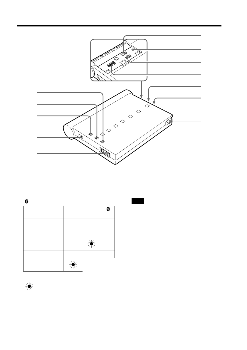
Identifying the parts
1
2
6
7
8
9
q;
qa
3
4
5
1 POWER lamp (green)
2 ON LINE lamp (orange)
3 lamp (blue)
Lamp POWER ON LINE
Communication
standby with a
Bluetooth device
Dialing
Data transmission
Insufficient
battery capacity
z : The lamp turns on
: The lamp flashes
4 DC IN jack
5 POWER ON/OFF switch
(green) (orange) (blue)
z – z
z z
zzz
qs
6 TONE/PULSE10/PULSE20 selector
7 CLEAR button
Note
Resets all the setup items to the default
values.
8 BONDING/NORMAL switch
9 AREA CODE switches (1–8)
0 Battery cover
qa Exclusive modem card slot
qs Exclusive modem card eject switch
7-GB

Preparing the unit
Before using the unit, carry out the following preparations. If the plug of the exclusive
modem cable does not match the telephone terminal jack, attach an optional plug
adaptor. The plug of the exclusive modem cable is an RJ-11 plug.
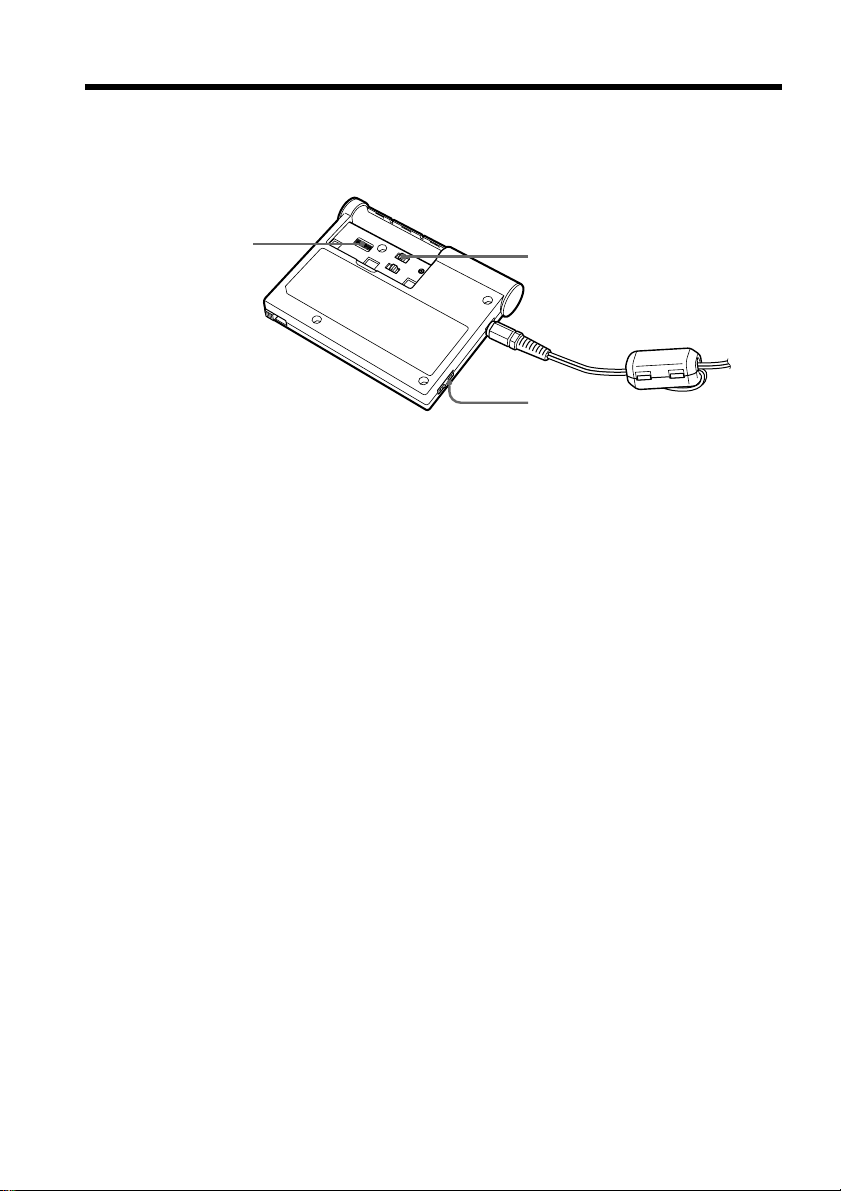
Installing the exclusive modem card and exclusive modem cable
to the Modem Adaptor with Bluetooth Function
12
Exclusive modem card eject switch
Incorrect
installation
(1) Insert the exclusive modem card firmly, with the v mark facing upward, into
the slot.
zTip
Once you insert the exclusive modem card, you can use the unit without ejecting
the exclusive modem card.
(2) Connect the exclusive modem cable to the exclusive modem card and the
telephone terminal jack.
v mark
To the telephone
terminal jack
Correct
installation
To eject the exclusive modem card
Push down the exclusive modem card eject switch.
Note
Do not eject the exclusive modem card while the POWER lamp is lit or flashing.
8-GB
Preparing the power supply
You can use either size AA alkaline dry batteries or the supplied AC power adaptor as
the power source. However, we recommend that you use the supplied AC power
adaptor.

Preparing the unit
x Using the supplied AC power adaptor
Connect the AC power adaptor to the DC IN jack on the unit and a wall outlet (mains).
AC power adaptor
AC-PT1
To a wall
outlet
(mains)
To a wall
outlet
(mains)
AC power adaptor
AC-PW1
Notes
•The socket outlet should be as close as possible to the unit and easily accessible.
•The shape of your AC power adaptor differs depending on your area.
or
x Installing the size AA alkaline dry batteries
The batteries are convenient for outdoor use of the unit.
To DC IN
Ribbon
123
(1) Remove the battery cover by sliding the cover in the direction of the arrow.
(2) Insert two size AA alkaline dry batteries with the correct 3 and # polarity
into the battery compartment and with the ribbon under the batteries.
(3) Replace the cover.
Note
We recommend that you use Sony size AA alkaline dry batteries.
zTip
The DC IN jack has source priority. If you use the unit using the AC power adaptor
with size AA alkaline dry batteries installed, the power is provided from the AC power
adaptor.
9-GB
Setting up the unit
You must make certain settings before you can connect the unit to your phone line.
Choose the proper settings for your telephone signaling type. You also have to set the
AREA CODE switches according to your area.
4
3
1
(1) Before making the settings, check that the POWER ON/OFF switch is set to
OFF.
(2) Remove the battery cover.
(3) Select the telephone signaling type with the TONE/PULSE10/PULSE20
selector.
TONE: When your phone line has tone signaling.
PULSE10: When your phone line has pulse signaling.
PULSE20: Normally, this is not used. For details, see “To check the dial speed
of a pulse dialing phone” on page 11.
zTips
•How can I tell if my phone has tone signaling?
You can hear the touch pad sound from your phone when you press the number
button.
•How can I tell if my phone has pulse signaling?
You can hear clicking sounds from your phone when you press the number
button.
10-GB
(4) Set up the AREA CODE switches according to your area.
For details, see “The setup of the AREA CODE switches” on page 11.
(5) Replace the cover.
The setting is completed.
Notes
•When the Bluetooth device you are communicating with can switch the telephone
signaling type, set it to the same setting as the unit. Otherwise, the connection will not
be established properly.
•If the TONE/PULSE10/PULSE20 selector is not set to the appropriate position, you
cannot communicate with any Bluetooth devices.
•If you cannot check the dial speed of your pulse dialing phone, set the TONE/
PULSE10/PULSE20 selector to PULSE10.

Setting up the unit
To check the dial speed of a pulse dialing phone
You can change the dialing speeds of some pulse dial phones. To check the dial speed,
switch the dial speed selector on the phone and check the clicking sound. The slower
one is the normal setting. When you select the fast dial speed, set the TONE/PULSE10/
PULSE20 selector to PULSE20.
The setup of the AREA CODE switches
Set the AREA CODE switches to the appropriate positions using a sharp-pointed object
following the information given in the table below. You cannot use the unit in areas
other than the areas indicated on the table.
AREA
CODE
switches
ON
12345678
The setup list for the AREA CODE switch
Country Parameter Country Parameter Country Parameter
or area or area or area
Austria 00001001 Greece 01000110 Portugal 10001011
Australia 00001010 Hong Kong 01010000 Singapore 10011100
Belgium 00001111 Ireland 01010111 Sweden 10100101
Canada 00100000 Japan 00000000 Switzerland 10100110
Denmark 00110001 Luxembourg 01101001 UK 10110100
Finland 00111100 Netherlands 01111011 USA 10110101
France 00111101 New Zealand 01111110
Germany 01000010 Norway 10000010
Notes
•“1” for the parameter in the table indicates that setting the switch to the ON side.
•The relationship between the 8-digit numbers in the table and the switch positions is
as illustrated below (e. g., for the USA).
ON
12345678
1 0 1 1 0 1 0 1
11-GB
 Loading...