

Page 1

4-187-302-12(1)
Blu-ray Disc/DVD
Home Theatre System
Operating Instructions
BDV-HZ970W / IZ1000W
©2010 Sony Corporation
Page 2
WARNING
Do not install the appliance in a
confined space, such as a bookcase
or built-in cabinet.
To reduce the risk of fire, do not
cover the ven tilation opening of the
apparatus with newspapers,
tablecloths, curtains, etc. Do not
place the naked flame sources such
as lighted candles on the apparatus.
Do not expose batteries or
apparatus with battery-installed to
excessive heat such as sunshine,
fire or the like.
To prevent injury, this apparatus
must be securely attached to the
floor/wall in accordance with the
installation instructions.
Indoor use only.
CAUTION
The use of optical instruments with
this product will increase eye
hazard. As the laser beam used in
this Blu-ray Disc / DVD Home
Theatre System is harmful to eyes,
do not attempt to disassemble the
cabinet.
Refer servicing to qualified
personnel only.
This appliance is classified as a
CLASS 3R LASER product.
Visible and invisible laser radiation
is emitted when the laser protective
housing is opened, so be sure to
avoid direct eye exposure.
This marking is located on the laser
protective housing inside the
enclosure.
This appliance is classified as a
CLASS 1 LASER product. The
CLASS 1 LASER PRODUCT
MARKING is located on the laser
protective housing inside the
enclosure.
Precautions
On power sources
• The unit is not disconnected from
the mains as long as it is
connected to the AC outlet, even
if the unit itself has been turned
off.
• As the main plug is used to
disconnect the unit from the
mains, connect the unit to an
easily accessible AC outlet.
Should you notice an abnormality
in the unit, disconnect the main
plug from the AC outlet
immediately.
On watching 3D video
images
Some people may experience
discomfort (such as eye strain,
fatigue, or nausea) while watching
3D video images. Sony
recommends that all viewers take
regular breaks while watching 3D
video images. The length and
frequency of necessary breaks will
vary from person to person. You
must decide what works be st. If you
experience any discomfort, you
should stop watching the 3D video
images until the discomfort ends;
consult a doctor if you believe
necessary. You should also review
(i) the instruction manua l and/or the
caution message of any other
device used with, or Blu-ray Disc
contents played with this product
and (ii) our website (http://
esupport.sony.com/) for the latest
information. The vision of young
children (especially those under six
years old) is still under
development. Consult your doctor
(such as a pediatrician or eye
doctor) before allowing young
children to watch 3D video images.
Adults should supervise young
children to ensure they follow the
recommendations listed above.
For the customers in
the U.S.A.
To reduce the risk of fire
or electric shock, do not
expose this apparatus to
rain or moisture.
These following indications are
located on the rear exterior.
This symbol is intended to
alert the user to the
presence of uninsulated
“dangerous voltage” within the
product’s enclosure that may be of
sufficient magnitude to constitute a
risk of electric shock to persons.
This symbol is intended to
alert the user to the
presence of important
operating and maintenance
(servicing) instructions in the
literature accompanying the
appliance.
Owner’s Record
The model and serial numbers are
located at the rear exterior of the
control unit. Record the serial
number in the space provided
below. Refer to them whenever you
call upon your Sony dealer
regarding this product.
Model No. BDV-HZ970W
Serial No.______________
The following FCC statement
applies only to the version of this
model manufactured for sale in the
U.S.A. Other versions may not
comply with FCC technical
regulations.
US
2
Page 3

NOTE:
This equipment has been tested and
found to comply with the limits for
a Class B digital device, pur suant to
Part 15 of the FCC Rules. These
limits are designed to provide
reasonable protection against
harmful interference in a residential
installation. This equipment
generates, uses, and can radiate
radio frequency energy and, if not
installed and used in accordance
with the instructions, may cause
harmful interference to radio
communications. However, there is
no guarantee that interference will
not occur in a particular
installation. If this equipment does
cause harmful interference to radio
or television reception, which can
be determined by turning the
equipment off and on, the user is
encouraged to try to correct the
interference by one or more of the
following measures:
– Reorient or relo cate the receiving
antenna (aerial).
– Increase the separation between
the equipment and receiver.
– Connect the equipment into an
outlet on a circuit different from
that to which the receiver is
connected.
– Consult the dealer or an
experienced radio/TV technici an
for help.
CAUTION
You are cautioned that any changes
or modifications not expressly
approved in this manual could void
your authority to operate this
equipment.
The shielded interface cable
recommended in this manual must
be used with this equipment in
order to comply with The limits for
a digital device pursuant to Subpart
B of Part 15 of FCC Rules.
Important Safety
Instructions
1) Read these instructions.
2) Keep these instructions.
3) Heed all warnings.
4) Follow all instructions.
5) Do not use this apparatus near
water.
6) Clean only with dry cloth.
7) Do not block any ventilation
openings. Install in accordance
with the manufacturer’s
instructions.
8) Do not install near any heat
sources such as radiators, heat
registers, stoves, or other
apparatus (including
amplifiers) that produce heat.
9) Do not defeat the safety
purpose of the polarized or
grounding-type plug. A
polarized plug has two blades
with one wider th an the other. A
grounding type plug has two
blades and a third grounding
prong. The wide blade or the
third prong are provided for
your safety. If the provided
plug does not fit into your
outlet, consult an electrician for
replacement of the obsolete
outlet.
10) Protect the power cord from
being walked on or pinched
particularly at plugs,
convenience receptacles, and
the point where they exit from
the apparatus.
11) Only use attachments/
accessories specified by the
manufacturer.
12) Use only with the cart, stand,
tripod, bracket, or table
specified by the manufacturer,
or sold with the apparatus.
When a cart is used, use caution
when moving the cart/
apparatus combination to avoid
injury from tip-over.
13) Unplug this apparatus during
lightning storms or when
unused for long periods of time.
14) Refer all servicing to qualified
service personnel. Servicing is
required when the apparatus
has been damaged in any way,
such as power-supply cord or
plug is damaged, liquid has
been spilled or objects have
fallen into the apparatus, the
apparatus has been exposed to
rain or moisture, does not
operate normally, or has been
dropped.
For the customers in
Canada
To reduce the risk of fire or electric
shock, do not expose this apparatus
to dripping or splashing, and do not
place objects filled with liquids,
such as vases, on the apparatus.
For the wireless
transceiver (EZWRT10/EZW-RT10A)
(For the customers in
the U.S.A.)
This equipment must not be colocated or operated in conjunction
with any other antenna or
transmitter.
This equipment c omplies with FCC
radiation exposure limits set forth
for uncontrolled equipment and
meets the FCC radio frequency
(RF) Exposure Guidelines in
Supplement C to OET65.
This equipment should be installed
and operated with at least 20cm and
more between the radiator and
person’s body (excluding
extremities: hands, wrists, feet and
ankles).
US
3
Page 4

For the wireless
transceiver (EZWRT10/EZW-RT10A)
(For the customers in
Canada)
This Class B digital apparatus
complies with Canadian ICES-003.
This device complies with RSSGen of IC Rules.
Operation is subject to the
following two conditions:
(1) this device may not cause
interference, and (2) this device
must accept any interference,
including interference that may
cause undesired operation of this
device.
This equipment complies with IC
radiation exposure limits set forth
for uncontrolled equipment and
meets RSS-102 of the IC radio
frequency (RF) Exposure rules.
This equipment should be installed
and operated with at least 20c m and
more between the radiator and
persons body (excluding
extremities: hands, wrists, feet and
ankles).
For the USB Wireless
LAN Adapter (UWABR100)
Pursuant to FCC regulations, you
are cautioned that any changes or
modifications not expressly
approved in this manual could void
your authority to operate this
equipment.
To prevent radio interferen ce to the
licensed service, this device is
intended to be operated i ndoors and
away from windows to provide
maximum shielding. Equipment (or
its transmit antenna) that is
installed outdoors is subject to
licensing.
Only use Wireless LAN indoors
when using it with IEEE 802.11a
(5 GHz).
High power radars are allocated as
primary users (meaning they have
priority) of 5250-5350 MHz and
5650-5850 MHz and these radars
could cause interference and/or
damage to this device.
This device uses 5 GHz band for
wireless LAN communication and
the maximum gain of the antenna in
this device is 5 dBi.
This equipment complies with
FCC/IC radiation exposure limits
set forth for an uncontrolled
environment. This equipment
should be installed and operated
with minimum distance 20 cm
between the radiator and your body
(excluding extremities: hands,
wrists and feet).
This device and its antenna(s) must
not be co-located or operating with
any other antenna or transmitter
except Grant condition.
If you have any questions about this
product, contact Sony Customer
Information Service Center at 1800-222-7669 or visit http://
www.sony.com/ on the Internet.
The telephone number below is for
FCC-related matters only.
Regulatory Information
Declaration of Conformity
Trade Name: SONY
Model: UWA-BR100
Responsible Party: Sony
Electronics Inc.
Address: 16530 Via Esprillo,
San Diego, CA 92127 U.S.A.
Telephone Number: 858-9422230
This device complies with part
15 of the FCC rules. Operation is
subject to the following two
conditions: (1) This device may
not cause harmful interference,
and (2) this device must accept
any interference received,
including interference that may
cause undesired operation.
Copyrights and
Trademarks
• This system incorporates with
Dolby* Digital and Dolby Pro
Logic (II) adaptive matrix
surround decoder and the DTS**
Digital Surround System.
* Manufactured under license
from Dolby Laboratories.
Dolby, Pro Logic, and the
double-D symbol are
trademarks of Dolby
Laboratories.
** Manufactured under license
under U.S. Patent #’s:
5,451,942; 5,956,674;
5,974,380; 5,978,762;
6,226,616; 6,487,535;
7,212,872; 7,333,929;
7,392,195; 7,272,567 &
other U.S. and worldwide
patents issued & pending.
DTS and the Symbol are
registered trademarks, &
DTS-HD, DTS-HD Master
Audio, and the DTS logos
are trademarks of DTS, Inc.
Product includes software.
© DTS, Inc. All Rights
Reserved.
• This system incorporates High-
Definition Multimedia Interface
TM
(HDMI
) technology.
HDMI, the HDMI logo and HighDefinition Multimedia Interface
are trademarks or registered
trademarks of HDMI Licensing
LLC.
• Java and all Java-based
trademarks and logos are
trademarks or registered
trademarks of Sun Microsystems,
Inc.
• “BD-LIVE” and
“BONUSVIEW” are trademarks
of Blu-ray Disc Association.
• “Blu-ray Disc” is a trademark.
• “Blu-ray Disc,” “DVD+RW,”
“DVD-RW,” “DVD+R,” “DVDR,” “DVD VIDEO,” and “CD”
logos are trademarks.
• “Blu-ray 3D” and “Blu-ray 3D”
logo are trademarks of Blu-ray
Disc Association.
US
4
Page 5

• “BRAVIA” is a trademark of
Sony Corporation.
• “AVCHD” and the “AVCHD”
logo are trademarks of Matsushita
Electric Industrial Co., Ltd. and
Sony Corporation.
• “S-AIR” and its logo are
trademarks of Sony Corporation.
• , “XMB,” and “xross media
bar” are trademarks of Sony
Corporation and Sony Computer
Entertainment Inc.
• “PLAYSTATION” is a trademark
of Sony Computer Entertainment
Inc.
®
•DivX
, DivX Certified® and
associated logos are registered
trademarks of DivX, Inc. and are
used under license. (Except for
U.S. models.)
• Music and video recognition
technology and related data are
provided by Gracenote
Gracenote is the industry standard
in music recognition technology
and related content delivery. For
more information, please visit
www.gracenote.com.
CD, DVD, Blu-ray Disc, and
music and video-rel ated data from
Gracenote, Inc., copyright ©
2000-present Gracenote.
Gracenote Software, copyright ©
2000-present Gracenote. One or
more patents owned by Gracenote
apply to this product and service.
See the Gracenote website for a
nonexhaustive list of applicable
Gracenote patents. Gracenote,
CDDB, MusicID, MediaVOCS,
the Gracenote logo and logotype,
and the “Powered by Gracenote”
logo are either registered
trademarks or trademarks of
Gracenote in the United States
and/or other countries.
• “PhotoTV H D” and the “PhotoTV
HD” logo are trademarks of Sony
Corporation.
®
.
• MPEG Layer-3 audio coding
technology and patents licensed
from Fraunhofer IIS and
Thomson.
• iPod is a trademark of Apple Inc.,
registered in the U.S. and other
countries.
• “Made for iPod” means that an
electronic accessory has been
designed to connect specifically
to iPod and has been certified by
the developer to meet Apple
performance standards.
• Apple is not responsible for the
operation of this device or its
compliance with safety and
regulatory standards.
• Windows Media is either a
registered trademark or trademark
of Microsoft Corporation in the
United States and/or other
countries.
®
, the DLNA Logo and
•DLNA
DLNA CERTIFIED™ are
trademarks, service marks, or
certification marks of the Digital
Living Network Alliance.
• Other system and product names
are generally trademarks or
registered trademarks of the
manufacturers. ™ and ® marks
are not indicated in this document.
About These Operating Instructions
• The instructions in these
Operating Instructions
describe the controls on the
remote. You can also use the
controls on the unit if they
have the same or similar
names as those on the remote.
• In this manual, “disc” is used
as a general reference for
BDs, DVDs, Super Audio
CDs, or CDs unless otherwise
specified by the text or
illustrations.
• The instructions in this
manual are for BDVHZ970W and BDVIZ1000W. BDV-HZ970W is
the model used for
illustration purposes. Any
difference in operation is
clearly indicated in the text,
for example, “BDVHZ970W.”
• The items displayed on the
TV screen may vary
depending on the area.
• The default setting is
underlined.
• The system is compatible
with the S-AIR function,
which allows transmission of
sound between S-AIR
products wirelessly. For
details on the S-AIR function,
see “Using an S-AIR
Product” (page 47).
• Notes or instructions for the
surround amplifier, surround
back amplifier, or S-AIR
receiver in these Operating
Instructions refer only to
when the surround amplifier,
surround back amplifier, or
S-AIR receiver is used.
US
5
Page 6

Table of Contents
About These Operating Instructions ....... 5
Unpacking............................................... 7
Index to Parts and Control .................... 10
Getting Started
Step 1: Installing the System .......16
Step 2: Connecting the System ...21
Step 3: Connecting to the
Network ....................................28
Step 4: Setting up the
S-AIR Wireless System...........29
Step 5: Performing the Easy
Setup ........................................30
Step 6: Selecting the Source .......32
Step 7: Enjoying Surround
Sound .......................................33
Playback
Playing a Disc ....................................... 35
Playing from a USB Device.................. 36
Enjoying an iPod................................... 37
Playing via a Network........................... 38
Available Options .................................40
Sound Adjustment
Selecting the Effect to Suit
the Source ....................................... 42
Selecting the Audio Format, Multilingual
Tracks, or Channel..........................42
Enjoying Multiplex Broadcast
Sound..............................................43
Using the Sound Effect......................... 44
Tuner
Listening to the Radio...........................45
External Audio Device
Using an S-AIR Product ....................... 47
Other Operations
Using the Control for HDMI Function for
“BRAVIA” Sync ............................ 51
Calibrating the Appropriate Settings
Automatically ................................. 53
Setting the Speakers ..............................54
Using the Sleep Timer ..........................56
Deactivating the Buttons on
the Unit.......................................... 56
Controlling Your TV or Other
Components with the Supplied
Remote ........................................... 57
Saving Power in Standby Mode ........... 59
Settings and Adjustments
Using the Setup Display ....................... 60
[Remote Controller Setting Guide] ...... 60
[Network Update]................................. 61
[Screen Settings]................................... 61
[Audio Settings].................................... 62
[BD/DVD Viewing Settings] ............... 63
[Parental Control Settings] ................... 63
[Music Settings].................................... 64
[System Settings].................................. 64
[Network Settings]................................ 65
[Easy Setup].......................................... 66
[Resetting] ............................................ 66
Additional Information
Precautions ........................................... 67
Notes about the Discs ........................... 68
Troubleshooting.................................... 69
Playable Discs ...................................... 76
Playable Types of Files ........................ 77
Supported Audio Formats..................... 78
Video Output Resolution ...................... 78
Specifications ....................................... 79
Language Code List.............................. 82
Glossary................................................ 83
Index ..................................................... 86
US
6
Page 7
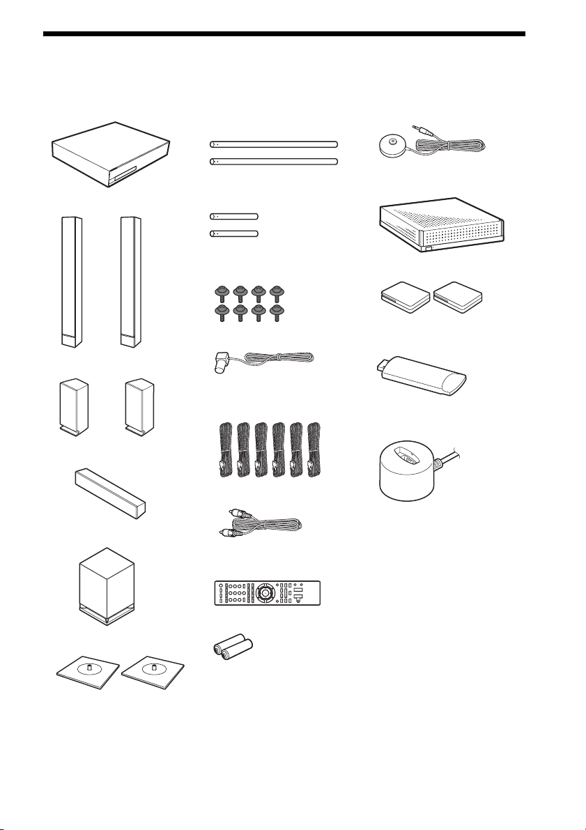
Unpacking
BDV-HZ970W
• Main unit (1)
• Posts for the front speakers
(long) (2)
• Calibration mic (1)
• Front speakers (2)
• Surround speakers (2)
• Center speaker (1)
• Subwoofer (1)
• Posts for the front speakers
(short) (2)
• Screws for the front speakers
(8)
• FM wire antenna (aerial) (1)
• Speaker cords (6, white/red/
blue/gray/green/purple)
• Video cord (1)
• Remote commander
(remote) (1)
• Surround amplifier (1)
• Wireless transceivers (2)
• USB Wireless LAN Adapter
(UWA-BR100)
• UWA-BR100 External
cable
• Operating Instructions
• Speaker Installation Guide
• Quick Setup Guide
• End user license agreement
• Easy Setup Disc (DVD)
• Bases for the front speakers (2)
• R6 (size AA) batteries (2)
US
7
Page 8
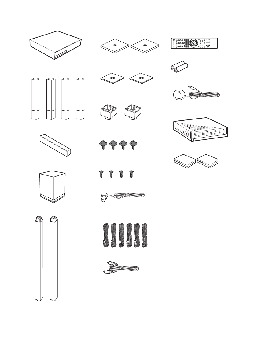
BDV-IZ1000W
• Main unit (1)
• Front and surround speakers
(4)
• Bases for the front speaker
stands (2)
• Bases for the surround
speakers (2)
• Base adapters for the surround
speakers (2)
• Remote commander
(remote) (1)
• R6 (size AA) batteries (2)
• Calibration mic (1)
• Surround amplifier (1)
• Center speaker (1)
• Subwoofer (1)
• Front speaker stands (2)
• Screws (with washer) for the
front speakers (4)
• Screws for the front speakers/
surround speakers (4)
• FM wire antenna (aerial) (1)
• Speaker cords (6, white/red/
blue/gray/green/purple)
•Video cord (1)
• Wireless transceivers (2)
• Operating Instructions
• Speaker Installation Guide
• Quick Setup Guide
• End user license agreement
• Easy Setup Disc (DVD)
US
8
Page 9
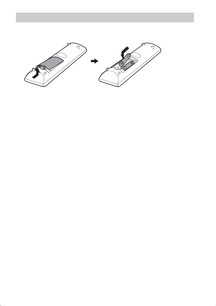
Preparing the remote
Insert two R6 (size AA) batteries (supplied) by matching the 3 and # ends on the batteries to the
markings inside the compartment.
US
9
Page 10
Index to Parts and Control
For more information, refer to the pages indicated in parentheses.
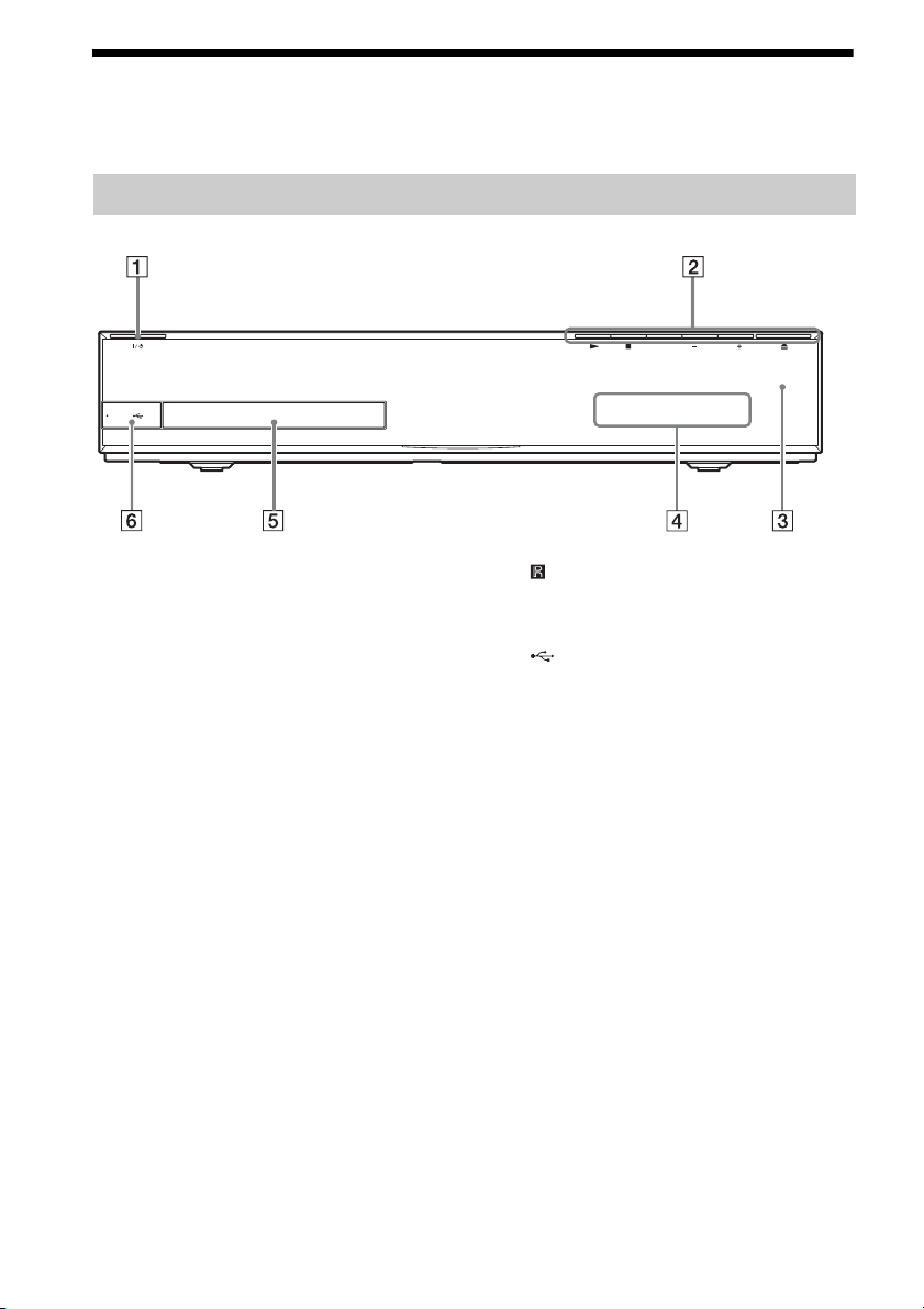
Front panel
PUSH OPEN
VOLUMEFUNCTION
A "/1 (on/standby)
Turns on the unit, or sets it to standby mode.
B Play operation buttons
N (play)
Starts or re-starts playback (resume play).
Plays a slideshow when a disc containing
JPEG image files is inserted.
x (stop)
Stops playback and remembers the stop
point (resume point).
The resume point for a title/track is the last
point you played or the last photo for a
photo folder.
FUNCTION
Selects the playback source.
VOLUME +/–
Adjusts the system’s volume.
Z (open/close) (page 35)
Opens or closes the disc tray.
C (remote sensor)
D Front panel display
E Disc tray (page 35)
F (USB) port (page 36)
Used for connecting a USB device.
10
US
Page 11
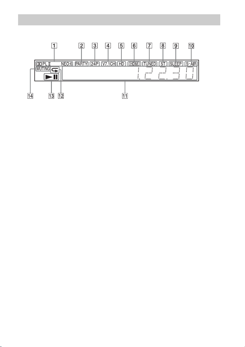
Front panel display
About the indications in the front panel display
A Displays the current sound format.
B Lights up when the system is playing
via the PARTY STREAMING function.
C Lights up when outputting 1920 ×
1080p/24 Hz video signals.
D Lights up while virtual 7.1ch decoding
is activated.
E Lights up when outputting 720p/1080i/
1080p video signals from the HDMI
(OUT) jack or 720p/1080i video signals
from the COMPONENT VIDEO OUT
jacks.
F Lights up when the HDMI (OUT) jack is
correctly connected to an HDCP (Highbandwidth Digital Content Protection)compliant device with HDMI or DVI
(Digital Visual Interface) input.
G Lights up when a radio station is
received. (Radio only) (page 45)
H Lights up when stereo sound is
received. (Radio only) (page 45)
I Flashes when the sleep timer is set.
(page 56)
J S-AIR indicator (only when the wireless
transceiver is inserted into the unit)
Lights up during wireless
transmission. When [Standby] is set to
[On], flashes when the main unit is in
standby mode and wireless
transmission between the main unit
and S-AIR receiver is not activated.
(page 47)
K Displays system’s status such as
chapter, title, or track number, time
information, radio frequency, playing
status, surround setting, etc.
L Lights up when repeat play is
activated.
M Displays system’s playing status.
N Lights up when muting is on.
11
US
Page 12
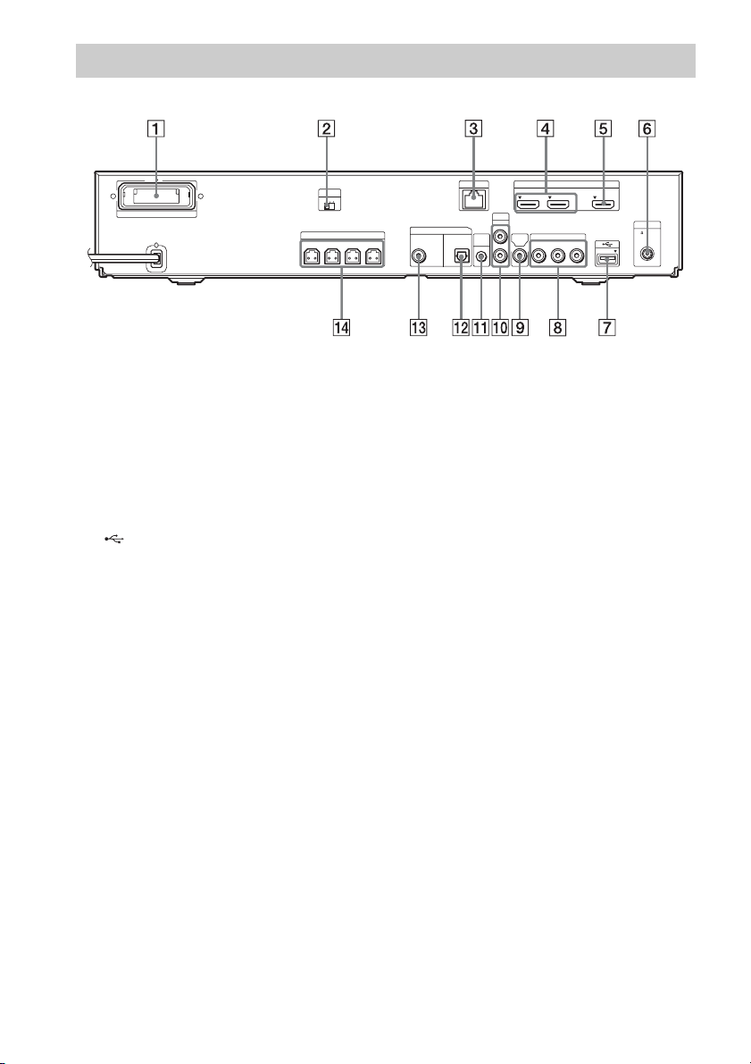
Rear panel
S-AIR ID
EZW-RT10
ABC
SPEAKERS
FRONT R FRONT L WOOFER CENTER
A Wireless transceiver (EZW-RT10) slot
(page 27)
B S-AIR ID switch (pages 29, 47)
C LAN (100) terminal (page 28)
D HDMI (IN 1/IN 2) jack (page 24)
E HDMI (OUT) jack (page 22)
F ANTENNA (75Ω COAXIAL FM) jack
(page 26)
G (USB) port (pages 28, 36)
IN 1 IN 2 OUT
VIDEO
COMPONENT VIDEO OUT
B/CBPR/CR
YP
OUT
HDMI
ARC
ANTENNA
75 COAXIAL
FM
DIGITAL IN
SAT/CABLE
COAX OPT
LAN(100)
AUDIO
AUDIO IN
L
TV
A.CAL
MIC
ECM-AC2
R
H COMPONENT VIDEO OUT jacks (page
22)
I VIDEO OUT jack (page 22)
J AUDIO (AUDIO IN L/R) jacks (page 24)
K A.CAL MIC jack (pages 30, 53)
L DIGITAL IN (TV OPT) jack (page 23)
M DIGITAL IN (SAT/CABLE COAX) jack
(page 24)
N SPEAKERS jacks (page 21)
12
US
Page 13
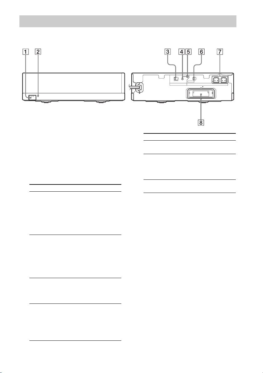
Surround amplifier
Front panel
S-AIR/STANDBY
A "/1 (Power)
Turns the surround amplifier on/off.
B S-AIR/STANDBY indicator
You can check the status of wireless
transmission of surround speaker audio
signals between the main unit and surround
amplifier.
Indicator Status
Turns green. Wireless transmission between
Flashes green
quickly.
Flashes green
slowly.
Turns red. Wireless transmission between
the main unit and the surround
amplifier is established
correctly and the main unit is
transmitting audio signals to
the surround speakers via the
surround amplifier.
Wireless transmission between
the main unit and the surround
amplifier is established
correctly, but audio signals to
the surround speakers are not
being transmitted by the main
unit.
Wireless transmission between
the main unit and the surround
amplifier is not set up
correctly.
the main unit and the surround
amplifier is not se t up, or either
the surround amplifier or the
whole system is in standby
mode.
Rear panel
ABC
S-AIR ID
PAIRING
SURROUND SELECTOR
SURROUND
EZW-RT10
SURROUND BACK
IMPEDANCE USE
SPEAKERS
L R
3-16
Indicator Status
Turns off. The surround amplifier is
turned off.
Flashes orange. The wireless transceiver is not
inserted/not fully inserted/
inserted upside-down into the
wireless transceiver slot.
Flashes red. The surround amplifier’s
protection is active.
C S-AIR ID switch
Selects the S-AIR ID.
D PAIRING button
Starts pairing.
E PAIRING indicator
Indicates the pairing status.
F SURROUND SELECTOR switch
Selects the mode for the surround amplifier.
G SPEAKERS jacks
H Wireless transceiver (EZW-RT10) slot
13
US
Page 14
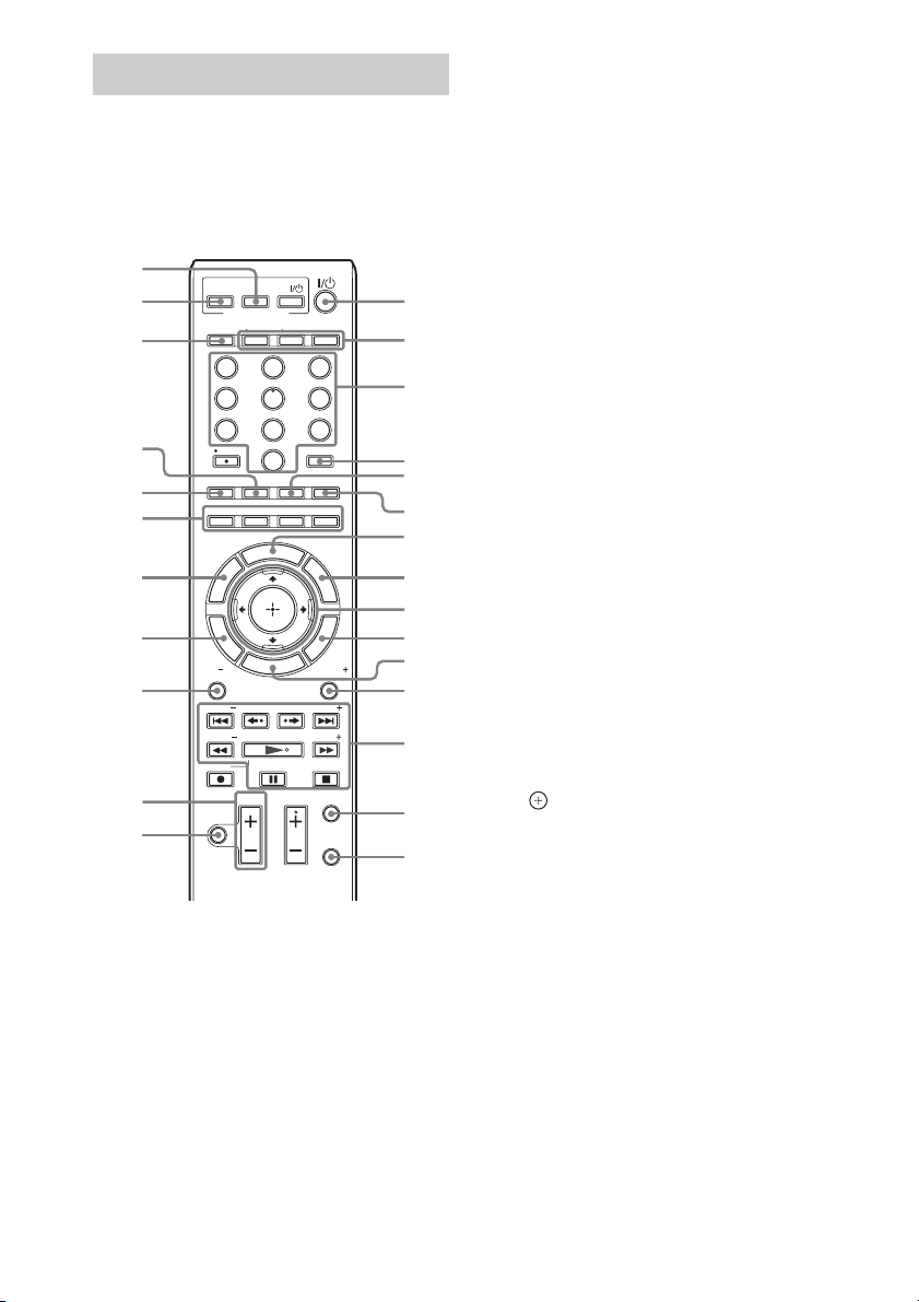
Remote control
The buttons for system operation only are
described below. See “Controlling Your TV or
Other Components with the Supplied Remote”
(page 57) for the buttons for operation of the
connected components.
wh
wg
wf
wd
ws
wa
w;
ql
qk
qj
qh
• Number 5, AUDIO, CH +, and N buttons
have a tactile dot. Use the tactile dot as a
reference when operating the remote.
• Names of buttons that work after pressing the
TV or STB operation mode buttons are
indicated with yellow label.
ONE-TOUCH
PLAY
BRAVIA Sync
AV
TVSTB BD
THEATER
321
654
987
ENTER
0
AUDIOCCSUBTITLE
YELLOW
E
D
I
U
G
R
E
T
PAG E PAG E
FUNCTION
PRESET PRESET
TUNING
REC
MUTING
D.TUNING
U
N
E
M
P
O
T
U
R
N
REPLAY ADVANCE
VOL
WIDE
TONE SLEEP
BLUE RED
R
I
T
O
E
V
A
F
H
E
O
M
M
U
E
N
PLAY
PAU SE STO P
CH
INPUT
GREEN
S
P
O
P
U
P
O
SOUND MODE
TUNING
DISPLAY
SYSTEM
/
M
E
N
T
P
MENU
JUMP
1
2
3
4
5
6
7
L
I
S
T
U
S
N
O
I
O
T
8
9
S
0
L
O
qa
qs
qd
qf
qg
A "/1 (on/standby) (pages 30, 45)
Turns on the system or sets it to standby
mode.
B Operation mode buttons (page 57)
Changes the component to be operated on
the remote.
STB: You can operate a cable box, digital
satellite receiver, digital video receiver, etc.
TV: You can operate a TV.
BD: You can operate this Blu-ray Disc/
DVD Home Theatre System.
C Number buttons (pages 46, 57)
Enters the title/chapter numbers, radio
frequencies, etc.
D ENTER (page 57)
Enters the selected item.
E TONE (page 44)
Adjusts the sound.
F SLEEP (page 56)
Sets the sleep timer.
G FAVORITES
Displays the contents of Internet entries
added to the Favorites List. You can save 18
favorite Internet contents.
H POP UP/MENU
Opens or closes the BD-ROM’s Pop-up
Menu, or the DVD’s menu.
I C/X/x/c
Moves the highlight to a displayed item.
(ENTER)
Enters the selected item.
J OPTIONS (page 40)
Displays the options menu on the TV
screen.
K HOME (pages 30, 45, 47, 53, 54, 60)
Enters or exits the system’s home menu.
L SOUND MODE (page 42)
Selects the sound mode.
14
US
Page 15

M Playback operation buttons
See “Playback” (page 35).
./> (previous/next)
Skip to the previous/next chapter, track, or
file.
REPLAY/ADVANCE
Briefly replay the current scenes for 10
seconds./Briefly fast forwards the current
scenes for 15 seconds.
m/M (fast reverse/fast forward)
Fast reverse/fast forward the disc during
playback. Each time you press the button,
search speed changes.
Activates slow-motion play when pressed
for more than one second in pause mode.
Plays one frame at a time when pressed in
pause mode.
N PLAY
Starts or re-starts playback (resume play).
Plays a slideshow when a disc containing
JPEG image files is inserted.
X PAUSE
Pauses or re-starts playback.
x STOP
Stops playback and remembers the stop
point (resume point). The resume point for
a title/track is the last point you played or
the last photo for a photo folder.
Radio operation buttons
See “Tuner” (page 45).
PRESET +/–
TUNING +/–
N DISPLAY (pages 35, 38)
Displays the playback information on the
TV screen.
Displays stream information in the front
panel display when: 1 The function is set
to “TV”/“SAT/CABLE”/“HDMI1”/
“HDMI2,” and 2 Digital signals are input
via the DIGITAL IN/HDMI (IN 1)/HDMI
(IN 2) jack.
O SYSTEM MENU (pages 33, 41, 44, 45)
Enters the system menu.
P MUTING
Turns off the sound temporarily.
Q VOL +/– (page 45)
Adjusts the volume.
R FUNCTION (pages 32, 45)
Selects the playback source.
S RETURN
Returns to the previous display.
T TOP MENU
Opens or closes the BD’s or DVD’s Top
Menu.
U Color buttons (YELLOW/BLUE/RED/
GREEN)
Shortcut keys for selecting items on some
Blu-ray menus (can also be used for Java
interactive operations on BDs).
V AUDIO (pages 42, 43)
Selects the audio format/track.
W SUBTITLE (page 63)
Selects the subtitle language when
multilingual subtitles are recorded on a BDROM/DVD VIDEO.
D.TUNING (Direct Tuning) (page 45)
Tunes in to the desired radio frequency.
X Z (open/close) (page 35)
Opens or closes the disc tray.
Y THEATER (page 52)
Switches to the optimum video mode for
watching movies automatically.
Z ONE-TOUCH PLAY (page 52)
Activates One-Touch Play.
15
US
Page 16
Getting Started
Step 1: Installing the System
Getting Started
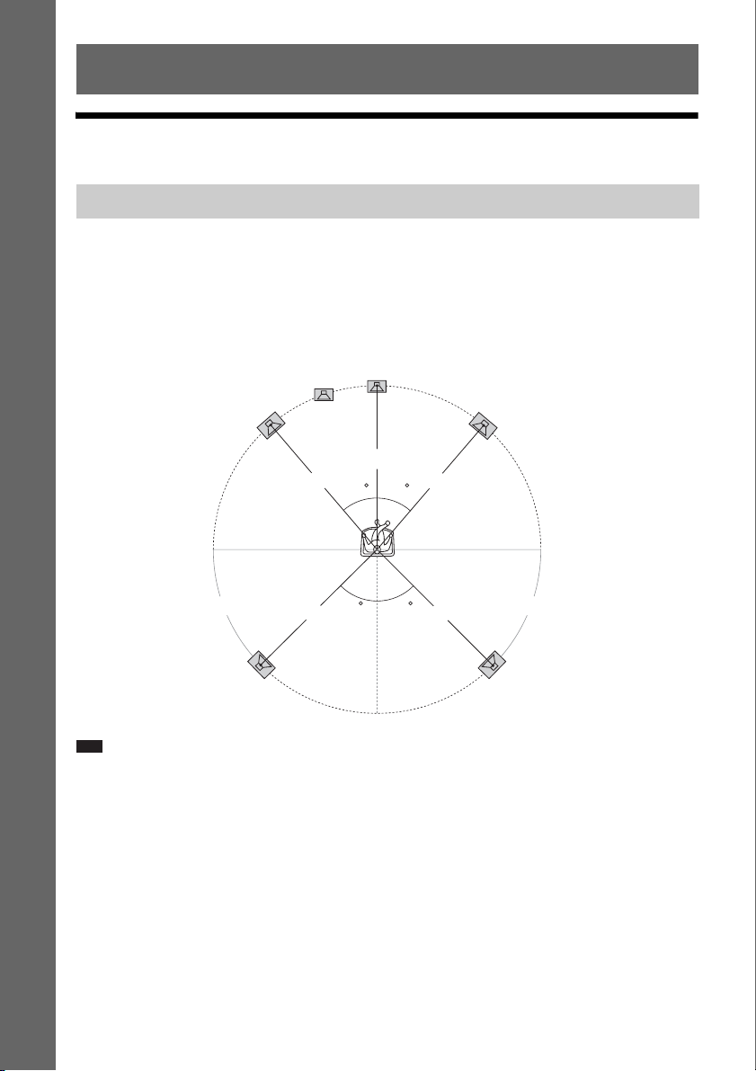
Positioning the speakers
For the best possible surround sound, place all speakers at the same distance from the listening position
(A). The distance can be between 0 to 23 feet (0.0 to 7.0 meters).
If you cannot place the center speaker and surround speakers at the same distance as (A), place them
within 23 feet (7.0 meters) of the listening position.
Place the surround speakers to the rear of the listening position (B).
The subwoofer can be placed anywhere in the room.
Subwoofer
Center speaker
Front left speaker (L)
Front right speaker (R)
A
A
30 30
B B
Surround left speaker (L)
Note
• Use caution when placing the speakers and/or speaker stands attached to the speakers on a specially treated (waxed,
oiled, polished, etc.) floor, as staining or discoloration may result.
• Do not lean or hang on a speaker, as it may fall down.
45
A
45
AA
Surround right speaker (R)
16
US
Page 17
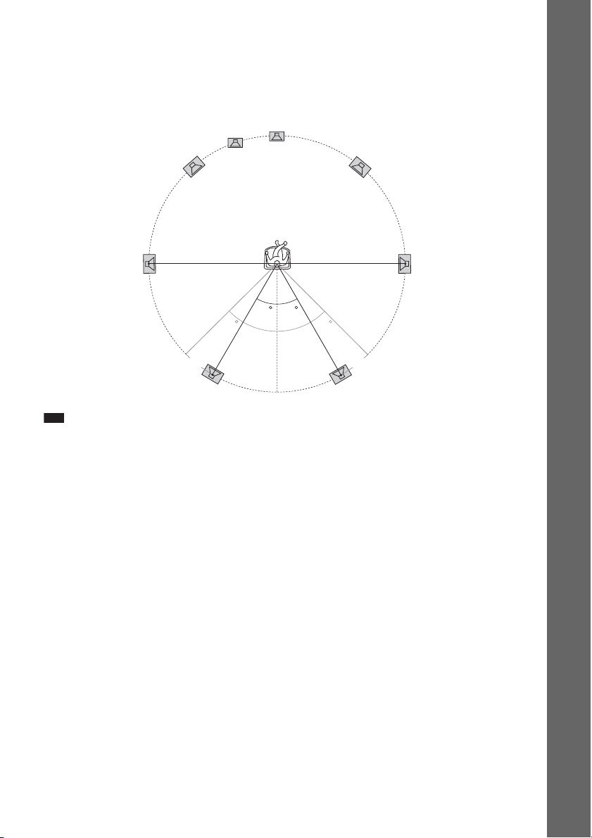
To add the optional surround back speakers
You can enjoy 7.1 surround sound by purchasing the Wireless Surround Speaker Kit (WAHT-SBP2,
optional). The optional product lineup differs depending on the area.
For the position of the surround back speakers, refer the illustration below (C).
Subwoofer
Center speaker
Getting Started
Front left speaker (L)
Surround left
speaker (L)
Surround back left speaker (L)
Note
30 30
45 45
CC
(optional)
Front right speaker (R)
Surround right
speaker (R)
Surround back right speaker (R)
(optional)
• To use the surround back speakers, set [Surround Back] (page 55) in [Speaker Settings] to [Yes] while performing
the Easy Setup (page 30).
17
US
Page 18
Assembling the speakers
For assembling the speakers, refer to “Speaker Installation Guide” (supplement).
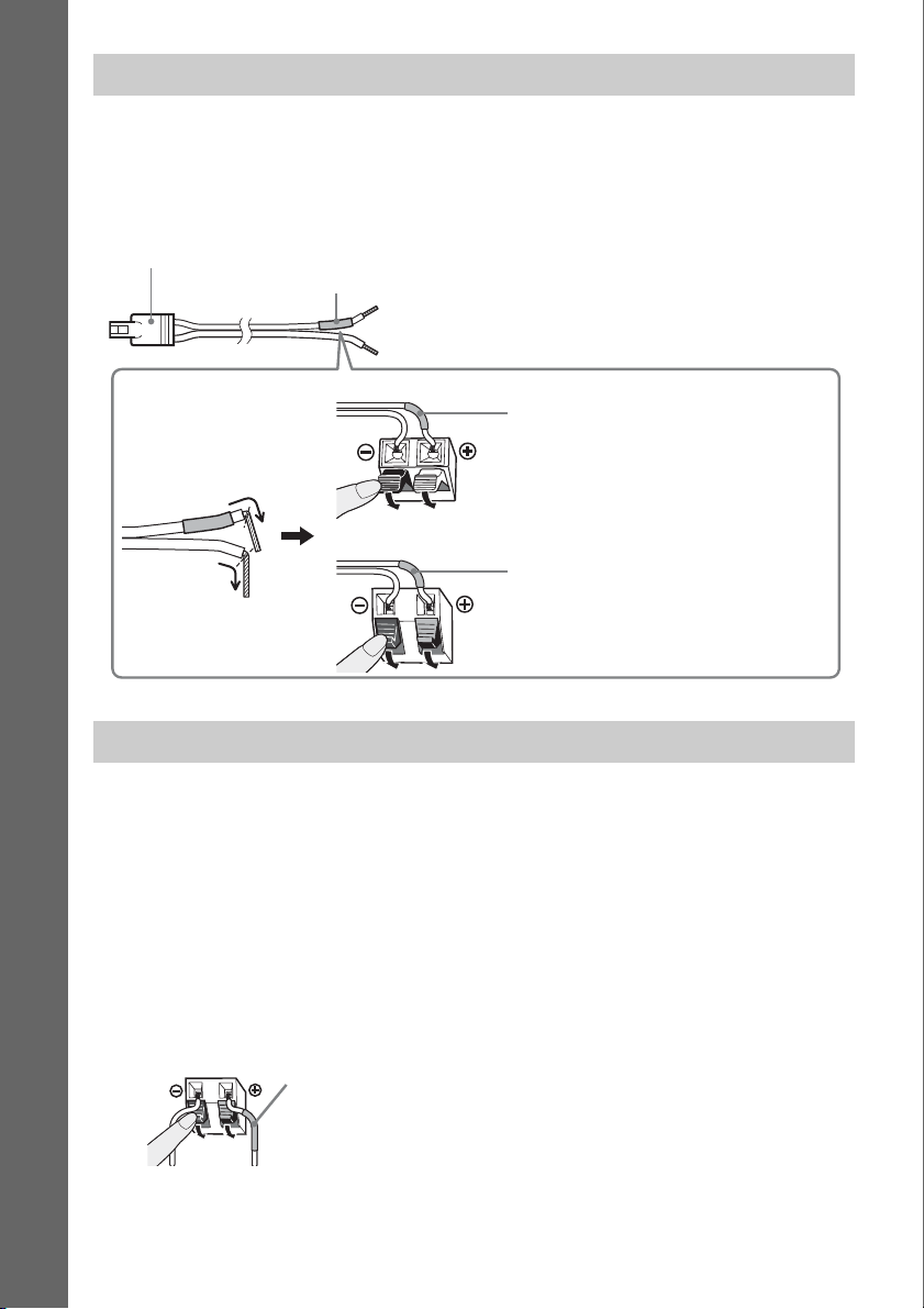
To connect speaker cords to the center speaker and subwoofer (BDVIZ1000W only)
Speaker terminals are located on the rear of the speakers.
Getting Started
Connector
Colored tube
(+)
(–)
Rear of the subwoofer
Purple colored tube
Rear of the center speaker
Green colored tube
When installing the speakers on a wall
Caution
• Contact a screw shop or installer regarding the wall material or screws to be used.
• Use screws that are suitable for the wall material and strength. As a plaster board wall is especially fragile, attach
the screws securely to a beam and fasten them to the wall. Install the speakers on a vertical and flat wall where
reinforcement is applied.
• Sony is not responsible for accidents or damage caused by improper installation, insufficient wall strength or
improper screw installation, natural calamity, etc.
To install the speakers on a wall
Before installing the speakers on a wall, connect the speaker cord to the speaker.
Be sure to match the speaker cords to the appropriate terminals on the speakers: the speaker cord with
the colored tube to 3, and the speaker cord without the colored tube to #.
Colored tube
Front left speaker (L): White
Front right speaker (R): Red
Center speaker: Green
Surround left speaker (L): Blue
Surround right speaker (R): Gray
US
18
Page 19
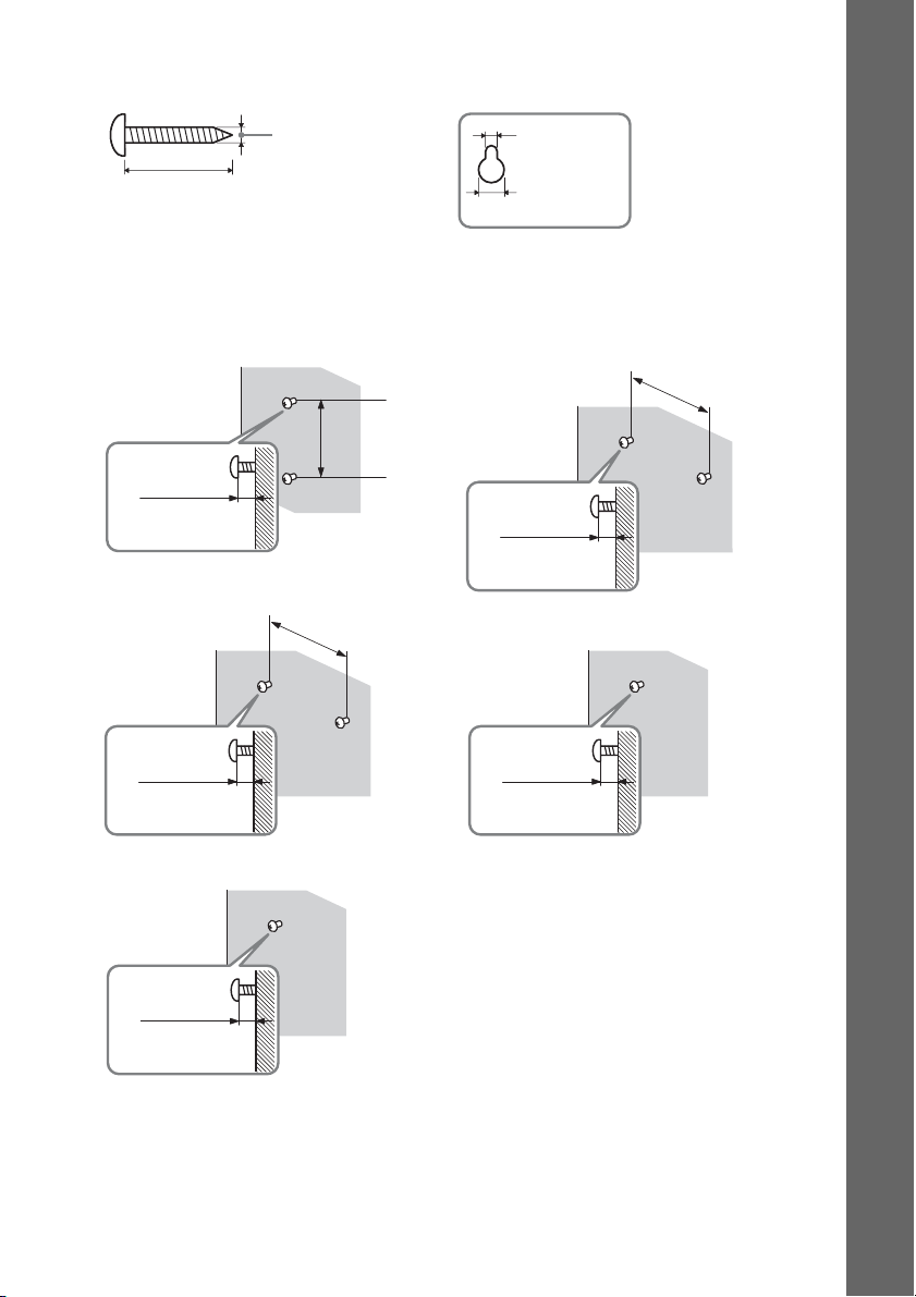
1 Prepare screws (not supplied) that are suitable for the hole on the back of each speaker.
See the illustrations below.
Hole on the back of
the speaker
30 mm (1 3/16 inches)
4 mm (
3
/16 inch)
5 mm
7
(
/32 inch)
10 mm
13
/32 inch)
(
2 Fasten the screws to the wall.
Getting Started
BDV-HZ970W
For the front speakers
8 to 10 mm
11
/32 to 13/32
(
For the center speaker
11
/32 to 13/32
(
For the surround speakers
inch
8 to 10 mm
inch
)
)
330 mm
13
inches)
(
219 mm
8 5/8 inches)
(
BDV-IZ1000W
For the center speaker
8 to 10 mm
11
/32 to 13/32
(
For the other speakers
11
/32 to 13/32
(
inch
8 to 10 mm
inch
)
)
219 mm
(
8 5/8 inches)
11
/32 to 13/32
(
8 to 10 mm
inch
)
US
19
Page 20
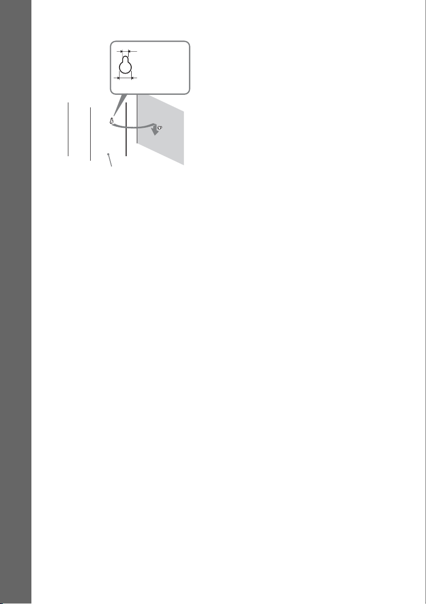
3 Hang the speakers on the screws.
Getting Started
5 mm
7
(
/32 inch)
10 mm
13
/32 inch)
(
Rear of the speaker
Hole on the back of
the speaker
20
US
Page 21
Step 2: Connecting the System
For connecting the system, read the information on the following pages.
Do not connect the AC power cord (mains lead) of the unit to a wall outlet (mains) until all the other
connections are made.
Note
• When you connect another component with a volume control, turn down the volume of the other components to a
level where sound is not distorted.
Connecting the speakers
The connector of the speaker cords and the color tube are color-coded depending on the type of speaker.
Connect the speaker cords to match the color of the SPEAKERS jacks of the unit.
Be sure to match the speaker cords to the appropriate terminals on the speakers: the speaker cord with
the color tube to 3, and the speaker cord without the color tube to #. Do not catch the speaker cord
insulation (rubber covering) in the speaker terminals.
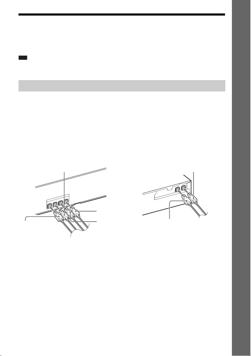
To connect speaker cords to the unit and surround amplifier
When connecting to the unit and surround amplifier, insert the connector until it clicks.
Getting Started
Rear panel of the unit
White
(Front left speaker (L))
NT R
FRO
Red
(Front right
speaker (R))
ON
FR
SPEAKERS
T L
Rear panel of the surround amplifier
Gray
(Surround right speaker (R))
LR
E
S
U
E
C
N
A
D
E
P
3-16
IM
S
R
E
K
A
E
P
ER CENTER
F
OO
W
S
Green
(Center speaker)
Purple
(Subwoofer)
Blue
(Surround left speaker (L))
21
US
Page 22
Connecting the TV (Video connection)
This connection sends a video signal to the TV.
Depending on the jacks on your TV, select the connection method.
Rear panel of the unit
Getting Started
C Video cord (supplied)
COMPONENT VIDEO OUT
VIDEO
OUT
1
IN
Y
C
R
A
T
U
HDMI
O
2
IN
R
/C
R
P
B
/C
B
P
A HDMI cable
(not supplied)
B Component video
cable (not supplied)
To the video input
jack of the TV.
To the component
video input jacks of
the TV.
To the HDMI IN jack
of the TV.
Method 1: HDMI cable (A) connection
If your TV has an HDMI jack, connect to the TV with an HDMI cable. Picture quality will be improved
compared to using the component video cable connection or the video cord connection.
When connecting with the HDMI cable, you need to select the type of output signal (page 61).
Method 2: Component video cable (B) connection
If your TV does not have an HDMI jack, but has component video input jacks, connect to the TV with
a component video cable. Picture quality will be improved compared to using the video cord
connection.
When connecting with the component video cable, you need to select the type of output signal (page
61).
Method 3: Video cord (C) connection
If you do not have an HDMI cable or a component video cable, make this connection.
US
22
Page 23
Connecting the TV (Audio connection)
This connection sends an audio signal to the unit from the TV. To listen to TV sound via the system,
perform this connection.
Rear panel of the unit
IN
L
A
IT
IG
D
V
T
E
T
L
P
B
O
A
/C
T
A
S
X
A
O
C
Digital optical cord
(not supplied)
To the digital optical out jack of
the TV.
With a digital audio connection, the system receives a Dolby Digital multiplex broadcast signal and
you can enjoy multiplex broadcast sound.
Note
• When you connect the TV and the unit with an audio cord, see “Connecting the other components” (page 24).
About Audio Return Channel (ARC)
If your TV is compatible with the Audio Return Channel function, an HDMI cable connection also
sends a digital audio signal from the TV. You do not need to make a separate audio connection for
listening to TV sound. For details of the Audio Return Channel function, see [Audio Return Channel]
(page 64).
Getting Started
23
US
Page 24
Connecting the other components
When another component you wish to connect to the system has an
HDMI OUT jack
You can connect a component that has an HDMI OUT jack such as a set-top box/digital satellite
receiver or PLAYSTATION®3, etc., with an HDMI cable. An HDMI cable connection can send both
video and audio signals. By connecting the system and the component using an HDMI cable, you can
enjoy high-quality digital pictures and sound via the HDMI (IN 1) or HDMI (IN 2) jack.
Getting Started
Rear panel of the unit
C
R
A
T
U
HDMI
O
2
IN
1
IN
HDMI cable (not
supplied)
To the HDMI OUT jack of the set-top box/
digital satellite receiver or
PLAYSTATION
®
3, etc.
Note
• Video signals to the HDMI (IN 1/IN 2) jacks are output from the HDMI (OUT) jack only when the “HDMI1” or
“HDMI2” function is selected.
• To output an audio signal from the HDMI (OUT) jack, you need to change the audio output setting. For details, see
[Audio Output] in [Audio Settings] (page 62).
US
24
Page 25
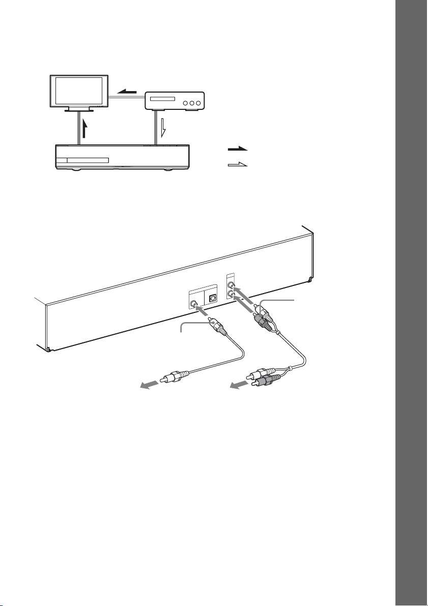
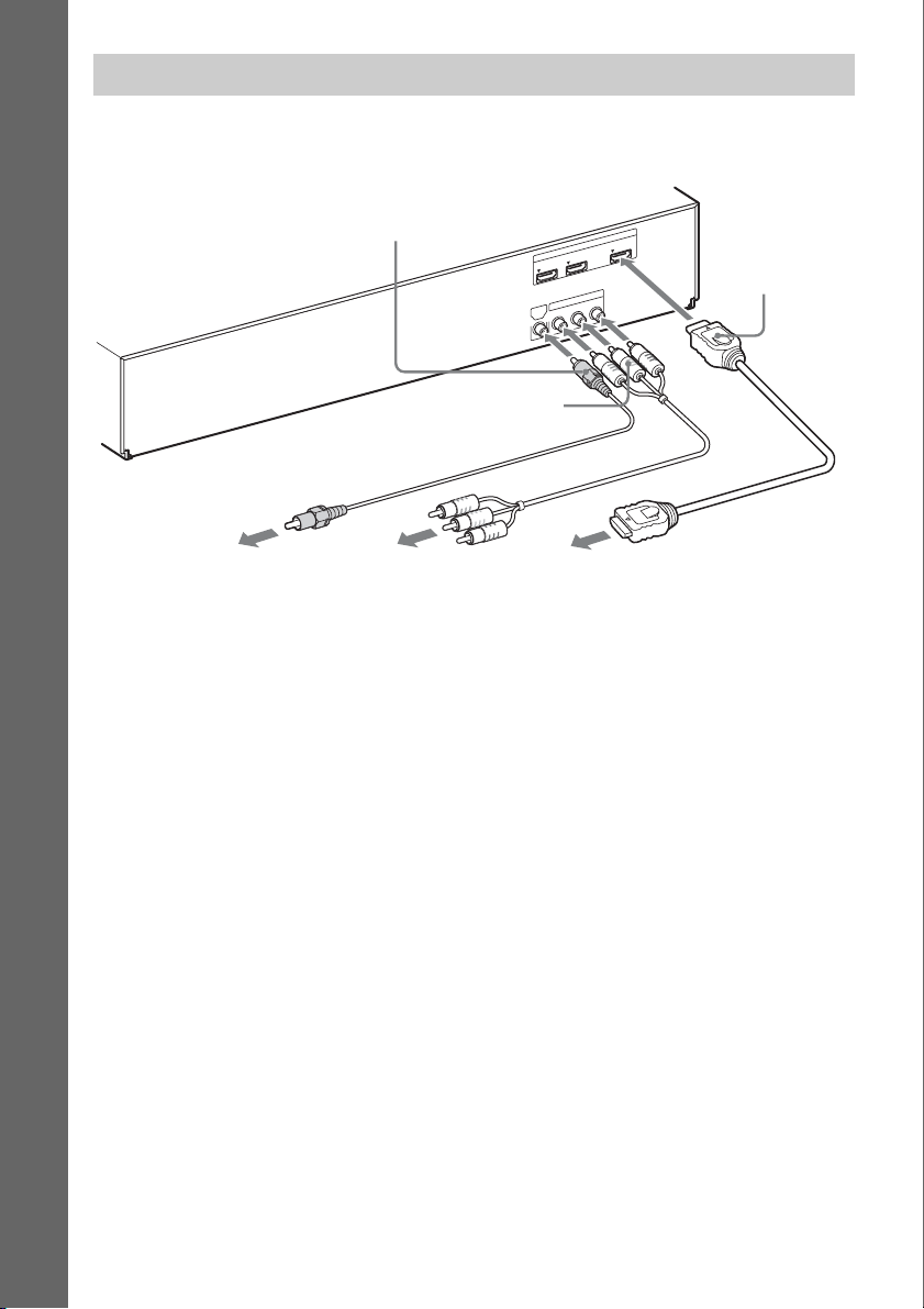
When the component does not have an HDMI OUT jack
Video signals from the system and the components are sent to the TV, and audio signals from the
components are sent to the system as follows.
TV
Getting Started
System
Signal flow
: Video signal
: Audio signal
You can enjoy connected components via the system’s speakers.
• VCR or digital satellite receiver, etc. (not supplied), which has a digital coaxial output jack: D
• VCR, digital satellite receiver, PlayStation, or portable audio source, etc. (not supplied): E
Rear panel of the unit
IO
D
U
A
IN
IO
D
U
A
L
IN
L
A
IT
IG
D
V
T
T
LE
P
B
O
A
/C
T
A
S
X
A
O
C
D Digital coaxial cord
(not supplied)
To the digital coaxial out jack
of the VCR or digital satellite
receiver, etc.
R
E Audio cord
(not supplied)
To the audio out jacks of the VCR,
digital satellite receiver, PlayStation,
or portable audio source, etc.
25
US
Page 26
p
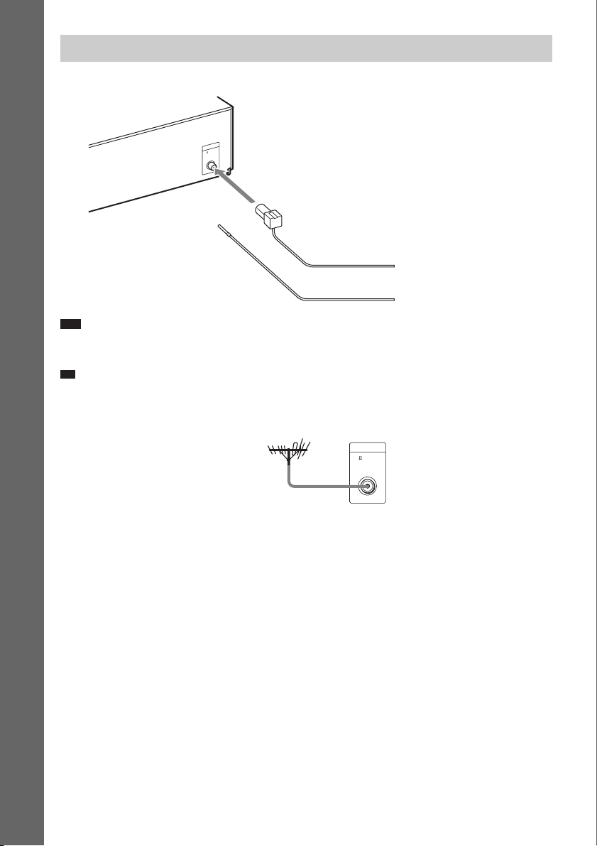
Connecting the antenna (aerial)
A
N
T
E
N
N
A
F
M
7
5
C
O
A
X
IA
L
Rear panel of the unit
Getting Started
or
FM wire antenna (aerial)
(supplied)
Note
• Be sure to fully extend the FM wire antenna (aerial).
• After connecting the FM wire antenna (aerial), keep it as horizontal as possible.
Ti
• If you have poor FM reception, use a 75-ohm coaxial cable (not supplied) to connect the unit to an outdoor FM
antenna (aerial) as shown below.
Unit
Outdoor FM antenna (aerial)
ANTENNA
75 COAXIAL
FM
US
26
Page 27
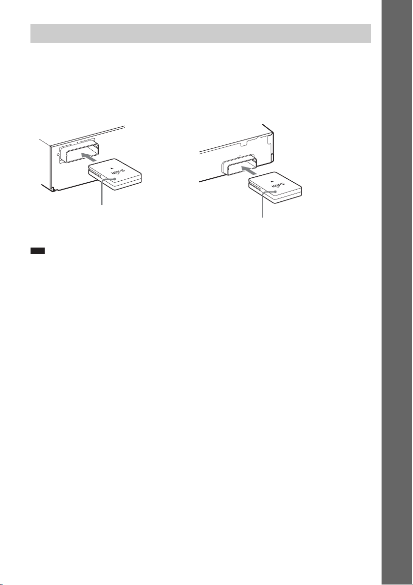
Inserting the wireless transceiver
You can transmit the audio signal from the main unit to an S-AIR product, such as the surround
amplifier or S-AIR receiver.
To transmit sound from the unit, insert one wireless transceiver into the main unit and the other one
into the S-AIR product, e.g. the surround amplifier.
For details of S-AIR products, see “Using an S-AIR Product” (page 47).
Rear panel of the unit
0
1
T
-R
W
Z
E
Wireless
transceiver
Note
• Please make sure to fully insert the wireless transceiver into the wireless transceiver slot. You should hear a click
when the wireless transceiver is inserted correctly.
• To avoid inserting the wireless transceiver upside-down, orient it with the Sony logo facing up.
Rear panel of the surround amplifier
0
1
T
R
-
W
Z
E
Wireless
transceiver
Getting Started
27
US
Page 28

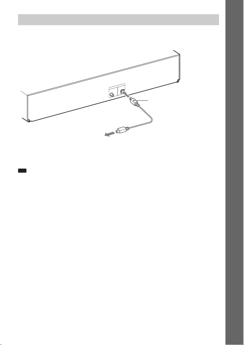
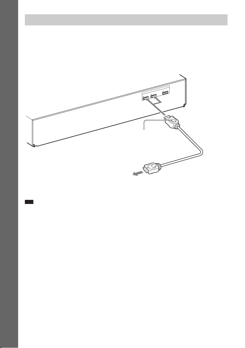
Step 3: Connecting to
p
p
the Network
Connecting the system to th e Internet allows you
to watch Internet video, listen to Internet audio,
use BD-LIVE, and update the Home Theatre
System software.
Getting Started
Wired Setup
Use a LAN cable to connect to the LAN (100)
terminal on the unit.
LAN cable
(not supplied)
Broadband
router
Ti
• Using a shielded LAN cable, straight or crossing, is
recommended.
ADSL modem/
cable modem
To set the network settings
Select [Network Settings], [Internet Settings],
then [Wired Setup] (page 65), and follow the onscreen instructions to complete the setup.
USB Wireless Setup
Use a wireless LAN via the USB Wireless LAN
Adapter (Sony UWA-BR100* only) (supplied
with BDV-HZ970W).
The USB Wireless LAN Adapter may not be
available in some regions/countries.
* As of January 2010.
Turn the unit off before connecting the
extension cable or inserting the USB Wireless
LAN Adapter. After inserting the USB Wireless
LAN Adapter to the base of the extension cable
and connecting the extension cable to the
(USB) port (front or rear), turn the unit on again.
Internet
LAN cable
(not supplied)
Wireless LAN
router
Note
• The placement distance between the USB Wireless
LAN Adapter and your wireless LAN router differs
depending on the usage environment. If the system
cannot connect to the network or the network
connection is unstable, move the USB Wireless LAN
Adapter to a different position or place the USB
Wireless LAN Adapter and the wireless LAN router
closer to each other.
ADSL modem/
cable modem
Internet
USB
Wireless
LAN
Adapter
To set the network settings
Select [Network Settings], [Internet Settings],
then [USB Wireless Setup] (page 65), and
follow the on-screen instructions to complete
the setup.
Ti
• For details on wireless network setup, please visit:
http://www.sony.com/blurayhtsupport
About wireless LAN security
Since communication via the wireless LAN
function is established by radio waves, the
wireless signal may be susceptible to
interception. To protect wireless
communication, this system supports various
security functions. Be sure to correctly
configure the security settings in accordance
with your network environment.
No Security
Although you can easily make settings, anyone
can intercept wireless communication or intrude
into your wireless network, even without any
sophisticated tools. Keep in mind that there is a
risk of unauthorized access or interception of
data.
US
28
Page 29

WEP
WEP applies security to communications to
prevent outsiders from intercepting
communications or intruding into your wireless
network. WEP is a legacy security technology
that enables older devices, which do not support
TKIP/AES, to be connected.
WPA-PSK (TKIP), WPA2-PSK (TKIP)
TKIP is a security technology developed to
correct for the deficiencies of WEP. TKIP
assures a higher security level than WEP.
WPA-PSK (AES), WPA2-PSK (AES)
AES is a security technology that uses an
advanced security method that is distinct from
WEP and TKIP.
AES assures a higher security level than WEP or
TKIP.
Step 4: Setting up the S-AIR Wireless System
Before performing Step 4
Make sure all connections are secure, and then
connect the AC power cords (mains leads).
To use the S-AIR wireless system, you need to
set up the surround amplifier.
The unit transmits sound to the surround
amplifier that is connected to the surround
speakers. To activate wireless transmission,
perform the following Steps.
1 Press "/1 to turn the system on.
"/1
Make sure that “S-AIR” light up in the front
panel display. W hen “S-AIR” does not light
up, make sure that the wireless transceiver
is inserted into the unit correctly.
2 Set the SURROUND SELECTOR switch
of the surround amplifier to
SURROUND.
SURROUND SELECTOR
SURROUND
SURROUND BACK
Getting Started
SURROUND SELECTOR
SURROUND
SURROUND BACK
3 Set the S-AIR ID switch of the surround
amplifier to A.
PAIRIN G
ABC
S-AIR ID
ABC
S-AIR ID
29
US
Page 30

4 Press "/1 to turn the surround amplifier
on.
When wireless transmission is activated,
the S-AIR/STANDBY indicator turns
green.
S-AIR/STANDBY indicator
Getting Started
About the standby mode
The surround amplifier enters standby mode
automatically (the S-AIR/STANDBY indicator
turns red) when the main unit is in standby mode
or wireless transmission is deactivated.
The surround amplifier turns on automatically
(the S-AIR/STANDBY indicator turns green)
when the system is turned on and wireless
transmission is activated.
S-AIR/STANDBY
"/1
If the S-AIR/STANDBY indicator does not
turn green, see “Surround amplifier”
(page 13).
For details of the S-AIR function, see
“Using an S-AIR Product” (page 47).
Step 5: Performing the Easy Setup
Follow the Steps below to make the basic
adjustments for using the system.
Displayed items vary depending on the country
model.
Note
• To use the optional surround back speakers, set
[Surround Back] in [Speaker Settings] to [Yes]
(page 55).
"/1
321
654
987
0
C/X/x/c,
HOME
30
1 Turn on the TV.
2 Connect the calibration mic to the
A.CAL MIC jack on the rear panel.
Set up the calibration mic at ear level using
a tripod, etc. (not supplied). The front of
each speaker should face the calibration
mic, and there should be no obstruction
between the speakers and the calibration
mic.
US
Page 31

L
A
.C
A
IC
M
2
C
-A
M
C
E
Calibration mic
3 Press [/1 on the unit, and [/1 on the
surround amplifier.
4 Switch the input selector on your TV so
that the signal from the system
appears on the TV screen.
The Easy Setup Display for OSD language
selection appears.
To recall the Easy Setup Display
1 Press HOME.
The home menu appears on the TV screen.
2 Press C/c to select [Setup].
3 Press X/x to select [Easy Setup], then
press .
4 Press C/c to select [Start], then press
.
The Easy Setup Display appears.
Getting Started
- OSD
Easy Setup
Select the language to be displayed by this unit.
English
Français
Español
Português
5 Perform the [Easy Setup]. Follow the
on-screen instructions to make the
basic settings using C/X/x/c, and .
For details about [Auto Calibration]
settings in [Easy Setup], see “Calibrating
the Appropriate Settings Automatically”
(page 53).
31
US
Page 32

Step 6: Selecting the Source
You can select the playback source.
Getting Started
FUNCTION
Press FUNCTION repeatedly until the
desired function appears in the front panel
display.
Each time you press FUNCTION, the function
changes as follows.
321
654
987
0
Function Source
“SAT/CABLE” Component that is connected to
the DIGITAL IN (SAT/CABLE
COAX) jack on the rear panel
(page 24)
“AUDIO” Component that is connected to
the AUDIO (AUDIO IN L/R)
jacks on the rear panel (page 24)
“BD/DVD” t “D. MEDIA” t “TUNER FM”
t “HDMI1” t “HDMI2” t “TV” t
“SAT/CABLE” t “AUDIO” t “BD/DVD”
t …
Function Source
“BD/DVD” Disc that is played by the system
“D. MEDIA” USB device, iPod, BRAVIA
“TUNER FM” FM radio (page 45)
“HDMI1”/
“HDMI2”
“TV” Component (TV, etc.) that is
US
32
Internet Video, or DLNA server
Component that is connected to
the HDMI (IN 1) or HDMI (IN 2)
jack on the rear panel (page 24)
connected to the DIGITAL IN
(TV OPT) jack on the rear panel,
or a TV compatible w ith the Audio
Return Channel function that is
connected to the HDMI (OUT)
jack on the rear panel (page 23).
Page 33

Step 7: Enjoying Surround Sound
After performing the previous Steps and starting playback, you can easily enjoy surround sound. You
can also select pre-programmed surround settings that are tailored to different kinds of sound sources.
They bring the exciting and powerful sound of movie theaters into your home.
321
654
987
0
X/x/c,
SYSTEM MENU
Selecting surround settings based on your listening preference
1 Press SYSTEM MENU.
2 Press X/x repeatedly until “SUR.SETTING” appears in the front panel display, then
press or c.
3 Press X/x repeatedly until the surround setting you want appears in the front panel
display.
See the table below for surround sound setting descriptions.
4 Press .
The setting is made.
5 Press SYSTEM MENU.
The system menu turns off.
Getting Started
About speaker output of each surround setting
The table below describes the options when you connect all the speakers to the unit.
The default setting is “A.F.D. 7.1CH.”
Sound from Surround setting Effect
Depending on the source. “A.F.D. STD”
(AUTO FORMAT
DIRECT STANDARD)
The system discriminates the sound format of the source and
presents sound as it was recorded/encoded.
33
US
Page 34

p
Sound from Surround setting Effect
“A.F.D. 7.1CH”
(AUTO FORMAT
DIRECT 7.1CH)
Getting Started
“PRO LOGIC”
“PLII MOVIE”
“PLII MUSIC”
“NEO6 CIN”
“NEO6 MUS”
“2CH STEREO” The system outputs the sound from the front speakers and
• 2 channel source: The system simulates surround sound
from 2 channel sources and outputs sound from the 5.1
channel speakers by duplicating 2 channel source sound
across each speaker.
• Mul ti-channel source: The system cre ates the surround back
sound virtually depending on the number of channels of the
source and outputs the sound as 7.1 channel surround sound.
• 2 channel source: The system simulates surround sound
from 2 channel sources and outputs sound from the 5.1
channel speakers.
– “PRO LOGIC” performs Dolby Pro Logic decoding.
– “PLII MOVIE” performs Dolby Pro Logic II movie
mode decoding.
– “PLII MUSIC” performs Dolb y Pro Logic II music mode
decoding.
• Multi-channel source: The system outputs sound from the
speakers depending on the number of channels of the
source.
• 2 channel source: The system simulates surround sound
from 2 channel sources and produces 6.1 channel sound.
– “NEO6 CIN” performs DTS Neo:6 Cinema mode
decoding.
– “NEO6 MUS” performs DTS Neo:6 Music mode
decoding.
• Multi-channel source: The system outputs sound from the
speakers depending on the number of channels of the
source.
subwoofer regardless of sound format or number of channels.
Multi-channel surround formats are downmixed to 2
channels.
Note
• When you select “A.F.D. 7.1CH,” depending on the disc or source, the beginning of the sound may be cut off while
the optimum mode is automatically selected. To avoid cutting the sound, select “A.F.D. STD.”
• When bilingual broadcast sound is input, “PRO LOGIC,” “PLII MOVIE,” and “PLII MUSIC” are not effective.
• Depending on the input stream, the surround settings may not be effective.
• When changing the surround setting while using the S-AIR receiver, sound from the S-AIR receiver may skip.
• When you play a Super Audio CD, surround settings are not activated.
Ti
• The system memorizes the last surround setting selected for each function.
Whenever you select a function such as “BD/DVD” or “TUNER FM,” the surround setting that was last applied to
the function is automatically applied again. For example, if you select “BD/DVD” with “PRO LOGIC” as the
surround setting, then change to another function, and then return to “BD/DVD,” “PRO LOGIC” will be applied
again.
US
34
Page 35

p
p
Playback
Playing a Disc
For playable discs, see “Playable Discs”
(page 76).
1 Switch the input selector on your TV so
that the signal from the system
appears on your TV screen.
2 Press Z, and place a disc on the disc
tray.
3 Press Z to close the disc tray.
appears on the home menu and playback
starts.
If playback does not start automatically,
select in the [Video], [Music], or
[Photo] category, and press .
Ti
• Delete unnecessary data in internal memory or USB
memory. Select [Erase BD Data] in [Video] to
delete unnecessary data. If you use USB memory as
local storage, all saved data in the [BUDA/BUDB]
folder is deleted. Make sure to backup any video/
music/photo data in the [BUDA/BUDB] folder.
Enjoying Blu-ray 3D
You can enjoy Blu-ray 3D Discs with the 3D
logo*.
*
1 Prepare for Blu-ray 3D Disc playback.
• Connect the system to your 3Dcompatible TV using a High-Speed
HDMI cable (not supplied).
• Set [3D Output Setting] and [TV Screen
Size Setting for 3D] in [Screen Settings]
(page 61).
2 Insert a Blu-ray 3D Disc.
The operation method differs depending on
the disc. Refer to the operating instructions
supplied with the disc.
Ti
• Refer also to the operating instructions of your 3Dcompatible TV.
Playback
Enjoying BONUSVIEW/BD-LIVE
Some BD-ROMs with “BD-LIVE” Logo* have
bonus content and other data that can be
downloaded for enjoyment.
*
1 Prepare for BONUSVIEW/BD-LIVE.
• Connect the unit to a network (page 28).
• Set [BD Internet Connection] to [Allow]
(page 63).
2 Insert a BD-ROM with BONUSVIEW/
BD-LIVE.
The operation method differs depending on
the disc. Refer to the operating instructions
of the disc.
35
US
Page 36

Displaying the play information
Playing from a USB
You can check the playback information, etc.,
by pressing DISPLAY.
The displayed information differs depending on
the disc type and player status.
Example: when playing a BD-ROM
A Output resolution/Video frequency
B Title number or name
C The currently selected audio setting
D Available functions ( angle, audio,
subtitle)
E Playback information
Displays disc type, play mode, repeat type,
video codec, bit rate, playing status bar,
playing time, total time
F Chapter number
G The currently selected angle
Device
You can play video/music/photo files on the
connected USB device.
For playable types of files, see “Playable Types
of Files” (page 77).
1 Connect the USB device to the
(USB) port on the unit.
Refer to the operating instructions of the
USB device before connecting.
Rear panel
USB device
Front panel
PUSH OPEN
USB device
2 Press C/c to select [Video],
[Music], or [Photo].
3 Press X/x to select [USB device
(front)] or [USB device (rear)], then
press .
Note
• Do not remove the USB device during
operation. To avoid data corruption or damage
to the USB device, turn the system off when
connecting or removing the USB device.
36
US
Page 37

Enjoying an iPod
You can enjoy the sound and charge the battery
of an iPod via the system.
Compatible iPod models
The compatible iPod models are as follows.
Update your iPod with the latest software before
using with the system.
1 Connect the iPod to the (USB) port
on the unit with the iPod’s USB cable.
2 Press C/c to select [Music].
3 Press X/x to select [iPod (front)],
then press .
The sound from the iPod is played on the
system.
You can operate the iPod using the buttons
on the remote.
For operation details, refer to the operating
instructions of the iPod.
To operate the iPod using the
remote
You can operate the iPod using the buttons on
the remote. The following table shows an
example of buttons that can be used.
Press Operation
N, X Same operation as the N/X button
x Pause.
m or M Fast reverse or forward.
. or > Same operation as the . or >
DISPLAY,
RETURN,
C
X/x Same operation as the Click Wheel
, c Same operation as the Center button
Note
• The iPod is charged when connected to the system
while the system is turned on.
• You cannot transfer songs onto the iPod.
• Sony cannot accept responsibility in the event that
data recorded to iPod is lost or damaged when using
an iPod connected to this unit.
• This product has been designed specifically to work
with iPod and has been certified to meet Apple
performance standards.
• Do not remove the iPod during operation. To avoid
data corruption o r damage to the iPod, turn t he system
off when connecting or removing the iPod.
of the iPod.
buttons of the iPod.
Same operation as the MENU button
of the iPod.
of the iPod.
of the iPod.
Playback
37
US
Page 38

Playing via a Network
Playing files stored on a DLNA server (DLNA Player)
Streaming BRAVIA Internet Video
BRAVIA Internet Video serves as a gateway
delivering the selected Internet content and a
variety of on-demand entertainment straight to
your unit.
1 Prepare for BRAVIA Internet Video.
Connect the unit to a network (page 28).
2 Press C/c to select [Video],
[Music], or [Photo].
3 Press X/x to select an Internet content
provider icon, then press .
When the Internet content list has not been
retrieved, it will be represented by an
unacquired icon or a new icon.
To use the control panel
The control panel appears when the video file
starts playing. The displayed items may differ
depending on Internet content providers.
To display again, press DISPLAY.
You can play video/music/photo files on your
home server, such as a DLNA-certified network
audio system or a PC with software that enables
a DLNA-certified server function, by
connecting the system to your home network.
1 Prepare for playing files on a DLNA
server.
• Connect the unit to a network (page 28).
• Set [Connection Server Settings]
(page 66).
2 Press C/c to select [Video],
[Music], or [Photo].
3 Press X/x to select a DLNA server, then
press .
The file list or folder list appears.
Playing the same audio in different rooms (PARTY STREAMING)
Note
• If [Party Auto Start] (page 66) is not displayed on the
TV screen, this function may be available via a future
update. However, the function may not be available
in some regions/countries.
A Control display
Press C/X/x/c or for playback operations.
B Playing status bar
Status bar, cursor indicating the current
position, playing time, duration of the video
file
C The next video file name
D The currently selected video file name and
rating
US
38
You can play the same audio at the same time
across all Sony components which are
compatible with the PARTY STREAMING
function.
The component that plays audio for the party
through the use of [Start Party] is called the
“party host.” A component that is invited to the
Page 39

party from the party host and plays the same
p
audio as the party host is called a “party guest.”
To start a party
(for the party host only)
You can use other components to play the
content that is playing on the system.
1 Turn on the system and other Sony
components compatible with the
PARTY STREAMING function.
Make sure that each component is
connected to the network.
2 Press C/X/x/c to select the audio
content in [Music] or a radio station.
For selecting a radio station, see “Listening
to the Radio” (page 45).
3 Press OPTIONS.
4 Press X/x to select [Start Party], then
press .
All party guests’ components start playing
the same audio content as the party host.
To join in a party
(for a party guest only)
You can use the system to play the content that
is playing on other components.
1 Turn on the system and other Sony
components compatible with the
PARTY STREAMING function.
Make sure that each component is
connected to the network.
2 Start a party on another networked
component.
3 Press C/c to select [Music].
4 Press X/x to select [Party], then
press .
5 Press X/x to select the party host that
you set up in Step 2, then press .
To close a party
For the party host
Press x, then press HOME.
For a party guest
Press OPTIONS, press X/x to select [Close
Party], then press in Step 3 above.
To leave from a party
(for a party guest only)
Press OPTIONS, press X/x to select [Leave
Party], then press .
Note
• The sale and product lineup of products that are
compatible with the PARTY STREAMING function
differ depending on the area.
Operating the system with a DLNA controller (DLNA renderer)
Note
• If [Renderer Options] (page 66) is not displayed on
the TV screen, this function may be available via a
future update. However, the function may not be
available in some regions/countries.
The system is compatible with the DLNA
renderer (network controlled player) function.
You can operate the system with a DLNA
controller.
For details of operation, see the operating
instructions of the DLNA controller.
Note
• Do not operate the system with the supplied remote
when operating the system by the DLNA controller.
Ti
• The sy stem is compatible with the “Play To” function
of Windows Media
with Windows 7.
®
Player 12 that comes standard
Playback
US
39
Page 40

Available Options
Various settings and playback operations are
available by pressing OPTIONS. The available
items differ depending on the situation.
Common options
Items Details
[Playback History
List]
[Search History] Searches for related
[Search Contents] Searches for BRAVIA
[Repeat Setting] Sets the repeat play.
[Favorites List] Displays the Favorites List.
[Play/Stop] Starts or stops playback.
[Play from beginning] Plays the item from the
[Information Display] Displays information on the
[Add to Favorites] Adds an Internet content to
[Remove from
Favorites]
Displays titles/tracks in the
playback history of a
BD-ROM/DVD-ROM/
CD-DA (music CD) using
Gracenote technology.
information based on
keywords from Gracenote via
the Information Display.
Internet Video content based
on keywords from Gracenote
via the Information Display.
beginning.
BD-ROM/DVD-ROM/
CD-DA (music CD) by using
Gracenote technology.
the Favorites List.
Erases an Internet content
from the Favorites List.
[Video] only
Items Details
[3D Output Setting] Sets whether or not to output
[Video Settings] • [Picture Quality Mode]:
[Play/Pause] Starts or pauses playback.
[Top Menu] Displays the BD’s or DVD’s
[Menu/Popup Menu] Displays the BD-ROM’s
[Title Search] Searches for a title on BD-
[Chapter Search] Searches for a chapter and
[Angle] Switches to other viewing
[IP Content Noise
Reduction]
3D video automatically.
Note
• 3D video from the HDMI
(IN 1) or HDMI (IN 2) jack
is output regardless of this
setting.
Selects the picture settings
for different lighting
environments.
• [FNR]: Reduces the random
noise appearing in the
picture.
• [BNR]: Reduces the
mosaic-like block noise in
the picture.
• [MNR]: Reduces minor
noise around the picture
outlines (mosquito noise).
Top Menu.
Pop-up Menu or DVD’s
menu.
ROMs/DVD VIDEOs and
starts playback from the
beginning.
starts playback from the
beginning.
angles when multi-angles are
recorded on BD-ROMs/DVD
VIDEOs.
Adjusts the video quality for
Internet content.
40
[Music] only
Items Details
[Add Slideshow
BGM]
US
Registers music files in the
USB memory as slideshow
background music.
Page 41

[Photo] only
Items Details
[Slideshow] Starts a slideshow.
[Slideshow Speed] Changes the slideshow speed.
[Slideshow Effect] Sets the effect when playing a
slideshow.
[Slideshow BGM] • [Off]: Turns off the
function.
• [My Music fro m USB]: Sets
the music files registered in
[Add Slideshow BGM]. If
no music file is registered,
[(Not registered)] is
displayed.
• [Play from disc]: Sets the
tracks on CD-DAs (music
CDs).
[Rotate Left] Rotates the photo
counterclockwise by
90 degrees.
[Rotate Right] Rotates the photo clockwise
by 90 degrees.
[View Image] Displays the selected picture.
Adjusting the delay between the picture and sound
(A/V SYNC)
When the sound does not match the pictures on
the TV screen, you can adjust the delay between
the picture and sound.
1 Press SYSTEM MENU.
2 Press X/x repeatedly until “A/V SYNC”
appears in the front panel display, then
press or c.
3 Press X/x to adjust the delay between
the picture and sound.
You can adjust from 0 ms to 300 ms in 25
ms increments.
4 Press .
The setting is made.
5 Press SYSTEM MENU.
The system menu turns off.
Note
• Depending on the input stream, A/V SYNC may not
be effective.
Playback
41
US
Page 42

Sound Adjustment
Selecting the Effect to Suit the Source
You can select a suitable sound mode for movies
or music.
321
654
987
0
• “GAME ROCK”: The system provides the
sound for music/rhythm games.
• “OMNI-DIR”: The same sound is audible
anywhere in the room.
Note
• Depending on the disc or source, when you select
“AUTO,” the beginning of the sound may be cut off
as the system selects the optimum mode
automatically. To avoid cutting the sound, select
other than “AUTO.”
• Depending on the input stream, the sound mode may
not be effective.
• When changing the sound mode while using the
S-AIR receiver, sound from the S-AIR receiver may
skip.
• When you play a Super Audio CD, this function does
not work.
SOUND
MODE
Press SOUND MODE repeatedly during
playback until the desired mode appears in
the front panel display.
• “AUTO”: The system selects “MOVIE” or
“MUSIC” automatically to produce the sound
effect depending on the disc or sound stream.
• “MOVIE”: The system provides the sound for
movies.
• “HD-D.C.S.”: For movies on Blu-ray and
DVD, etc., “HD-D.C.S.” realizes precise
sound effects the way the Movie Sound
Designers intended for them to be.
• “3D SUR.”: “3D SUR.” is a unique Sony
algorithm used for playing 3D (threedimensional) content that provides a 3D sound
experience with depth and presence by
creating a virtual sound field close to your
ears.
• “MUSIC”: The system provides the sound for
music.
• “SPORTS”: The system adds reverberation for
sports programs.
• “NEWS”: The system provides the sound for
voice programs, such as news.
Selecting the Audio Format, Multilingual Tracks, or Channel
When the system is playing a BD/DVD VIDEO
or DATA CD/DATA DVD (DivX video files*)
recorded in multiple audio formats (PCM,
Dolby Digital, MPEG audio, or DTS) or
multilingual tracks, you can change the audio
format or language.
With a CD, you can select the sound from the
right or left channel and listen to the sound of the
selected channel through both the right and left
speakers.
* Except for U.S. models.
321
654
987
AUDIO
0
42
US
Page 43

Press AUDIO repeatedly during playback to
select the desired audio signal.
The audio information appears on the TV
screen.
x BD/DVD VIDEO
Depending on the BD/DVD VIDEO, the choice
of language varies.
When 4 digits are displayed, they indicate a
language code. See “Language Code List”
(page 82) to confirm which language the code
represents. When the same language is
displayed two or more times, the BD/DVD
VIDEO is recorded in multiple audio formats.
x DVD-VR
The types of sound tracks recorded on a disc are
displayed.
Example:
• [ Stereo]
• [ Stereo (Audio1)]
• [ Stereo (Audio2)]
•[ Main]
•[ Sub]
• [ Main/Sub]
Note
• [ Stereo (Audio1)] and [ Stereo (Audio2)] do not
appear when only one audio stream is recorded on the
disc.
x DATA CD (DivX video file)/DATA DVD
(DivX video file) (Except for U.S. models)
The choice of DATA CD or DATA DVD audio
signal formats differs, depending on the DivX
video file contained on the disc. The format
appears on the TV screen.
x CD
•[ Stereo]: The standard stereo sound.
• [ 1/L]: The sound of the left channel
(monaural).
• [ 2/R]: The sound of the right channel
(monaural).
Enjoying Multiplex Broadcast Sound
(DUAL MONO)
You can enjoy multiplex broadcast sound when
the system receives or plays a Dolby Digital
multiplex broadcast signal.
Note
• To receive the Dolby Digital signal, you need to
connect a TV or other component to the unit with a
digital coaxial or optical cord (pages 23, 24). If your
TV is compatible with the Audio Return Channel
function (page 53), you can receive a Dolby Digital
signal via an HDMI cable.
321
654
987
AUDIO
Press AUDIO repeatedly until the desired
signal appears in the front panel display.
•“MAIN”: Sound of the main language will be
output.
• “SUB”: Sound of the sub language will be
output.
• “MAIN/SUB”: Mixed sound of both the main
and sub languages will be output.
0
Sound Adjustment
43
US
Page 44

Using the Sound Effect
321
654
987
0
C/X/x/c,
Enjoying sound at low volume
You can enjoy sound effects or dialog, as you
would in a movie theater, even at low volume. It
is useful for watching movies at night.
1 Press SYSTEM MENU.
2 Press X/x repeatedly until “NIGHT
MODE” appears in the front panel
display, then press or c.
3 Press X/x to select a setting.
• “NIGHT ON”: On.
• “NIGHT OFF
”: Off.
4 Press SYSTEM MENU.
The system menu turns off.
Note
• When sound is output from the center speaker, this
effect is more pronounced, as speech (movie dialog,
etc.) is easy to hear. When sound is not output from
the center speaker, the system optimally adjusts the
volume.
TONE
SYSTEM
MENU
Changing the tonal balance
You can adjust the sound by changing the tonal
balance of the sound.
1 Press TONE repeatedly until the
desired setting appears in the front
panel display.
• “BASS”: You can adjust the bass
frequencies.
• “TREBLE”: You can adjust the treble
frequencies.
2 Press X/x to adjust the sound.
The adjusted value appears in the front
panel display. You can set the value from
–6.0 to +6.0.
44
US
Page 45

Tuner
321
654
987
0
Listening to the Radio
You can enjoy radio sound with the system’s
speakers.
"/1
Number
buttons
D.TUNING
Manual tuning
Press TUNING +/– repeatedly.
3 Adjust the volume by pressing
VOL +/–.
If an FM program is noisy
If an FM program is noisy, you can select
monaural reception. There will be no stereo
effect, but reception will improve.
1 Press SYSTEM MENU.
2 Press X/x repeatedly until “FM MODE”
appears in the front panel display.
Tuner
C/X/x/c,
FUNCTION
TUNING +/–
VOL +/–
Current station
Current band and preset number
FM 7
MHz
88.00
1 Press FUNCTION repeatedly until
“TUNER FM” appears in the front panel
display.
2 Select the radio station.
Automatic tuning
Press and hold TUNING +/– until the auto
scanning starts.
[Auto Tuning] appears on the TV screen.
Scanning stops when the system tunes in a
station.
To stop the automatic tuning manually,
press TUNING +/–.
PRESET +/–
x
SYSTEM
MENU
3 Press or c.
4 Press X/x to select “MONO.”
• “STEREO”: Stereo reception.
• “MONO”: Monaural reception.
5 Press SYSTEM MENU.
The system menu turns off.
To turn off the radio
Press "/1.
Presetting radio stations
You can preset up to 20 stations. Before tuning,
make sure to turn down the volume to minimum.
1 Press FUNCTION repeatedly until
“TUNER FM” appears in the front panel
display.
2 Press and hold TUNING +/– until the
auto scanning starts.
Scanning stops when the system tunes in a
station.
3 Press SYSTEM MENU.
4 Press X/x repeatedly until “MEMORY”
appears in the front panel display, then
press or c.
A preset number appears in the front panel
display.
45
US
Page 46

5 Press X/x to select the preset number
p
p
you want.
Ti
• You can select the preset number directly by
pressing the number buttons.
6 Press .
“COMPLETE” appears in the front panel
display, and the station is stored.
7 Repeat Steps 2 to 6 to store other
stations.
8 Press SYSTEM MENU.
The system menu turns off.
To change the preset number
Select the desired preset number by pressing
PRESET +/–, then perform the procedure from
Step 3.
Selecting the preset station
1 Press FUNCTION repeatedly until
“TUNER FM” appears in the front panel
display.
The last received station is tuned in.
2 Press PRESET +/– repeatedly to select
the preset station.
The preset number and frequency appear on
the TV screen and front panel display.
Each time you press the button, the system
tunes in one preset station.
Ti
• Y ou can select the preset station nu mber directly
by pressing the number buttons.
Selecting a radio station by inputting a frequency directly
When you know the frequencies, you can select
radio stations by inputting the frequencies
directly.
1 Press FUNCTION repeatedly until
“TUNER FM” appears in the front panel
display.
2 Press D.TUNING.
3 Press the number buttons to select the
frequencies.
4 Press .
US
46
Page 47

External Audio Device
To set the ID of the unit
1 Set the S-AIR ID switch of the unit to
the desired ID.
Using an S-AIR Product
About S-AIR products
There are two types of S-AIR product.
• S-AIR main unit (this unit): This is for
transmitting sound. You can use up to three
S-AIR main units. (The number of usable
S-AIR main units depends on the use
environment.)
• S-AIR sub unit: This is for receiving sound.
– Surround amplifier (supplied): You
can enjoy surround speaker sound
wirelessly.
– S-AIR receiver (optional): You can
enjoy system sound in another room.
Room A
S-AIR sub unit
(surround amplifier)
Room B
Setting the S-AIR ID to activate wireless transmission
For the surround amplifier
For the S-AIR receiver
S-AIR main unit
S-AIR sub unit
(S-AIR receiver)
(not supplied)
S-AIR ID
ABC
S-AIR ID switch
You can select any ID (A, B, or C).
2 Press "/1.
The system turns on.
3 Set the S-AIR sub unit to the same ID.
Wireless transmission is activated as
follows (example):
ID A
ID A ID A
To set the ID of the surround
amplifier
1 Make sure that the SURROUND
SELECTOR switch of the surround
amplifier is set to SURROUND.
2 Set the S-AIR ID switch of the surround
amplifier to match the ID (A, B, or C) of
the unit.
3 Press "/1 on the surround amplifier.
When wireless transmission is activated,
the S-AIR/STANDBY indicator of the
surround amplifier turns green.
For details of the S-AIR/STANDBY
indicator, see “Surround amplifier”
(page 13).
External Audio Device
Simply by matching the ID of the unit and the
S-AIR sub unit, you can activate wireless
transmission.
To set the ID of the S-AIR
receiver
Refer to the operating instructions of the S-AIR
receiver.
47
US
Page 48

To enjoy a 7.1 channel system
You can enjoy the more realistic surround sound
effect of 7.1 channels when you use the Wireless
Surround Speaker Kit (WAHT-SBP2, optional).
For details, refer to the operating instructions of
the Wireless Surround Speaker Kit.
In this case, set [Surround Back] in [Speaker
Settings] to [Yes] (page 55).
9 Adjust the volume on the S-AIR
receiver.
Enjoying the S-AIR receiver while the unit is in standby mode
For the S-AIR receiver
Enjoying the system’s sound in another room
For the S-AIR receiver
You can enjoy the system’s sound in another
room by using the S-AIR receiver.
1 Press HOME.
The home menu appears on the TV screen.
2 Press C/c to select [Setup].
3 Press X/x to select [System Settings],
then press .
4 Press X/x to select [S-AIR Settings],
then press .
The [S-AIR Settings] display appears.
5 Press X/x to select [Mode], then press
.
6 Press X/x to select the desired setting.
•[Party]: The S-AIR receiver outputs
sound according to functions set on the
unit.
• [Separate]: You can set the desired
function for the S-AIR receiver while unit
functions do not change.
7 Press .
The setting is made.
8 When you select [Separate] in Step 6,
press S-AIR CH on the S-AIR receiver
to select the function.
The S-AIR receiver’s function changes as
follows.
“MAIN UNIT” t “TUNER FM” t
“AUDIO” t …
You can enjoy the S-AIR receiver while the unit
is in standby mode by setting [Standby] to [On].
1 Press HOME.
The home menu appears on the TV screen.
2 Press C/c to select [Setup].
3 Press X/x to select [System Settings],
then press .
4 Press X/x to select [S-AIR Settings],
then press .
The [S-AIR Settings] display appears.
5 Press X/x to select [Standby], then
press .
6 Press X/x to select the desired setting.
• [On]: You can enjoy the S-AIR receiver
while the unit is in standby mode or turned
on. The power consumption during
standby mode increases.
•[Off]
: You cannot enjoy the S-AIR
receiver while the unit is in standby mode.
7 Press .
The setting is made.
Note
• When you turn the system off while [Standby] is set
to [On], “S-AIR” flashes (when wireless transmission
between the unit and S-AIR receiver is not activated),
or lights up (when wireless transmission between the
unit and S-AIR receiver is activated) in the front
panel display.
48
To enjoy the same function as the unit,
select “MAIN UNIT.”
US
Page 49

Identifying the unit with a specific S-AIR sub unit (Pairing operation)
For the surround amplifier
For the S-AIR receiver
When using S-AIR products, neighbors may
also receive your system’s sound if IDs are the
same, or you may receive sound from neighbors.
To prevent this, you can identify the unit with a
specific S-AIR sub unit by performing the
pairing operation.
When you perform pairing, wireless
transmission is activated between the paired
main unit and S-AIR sub unit only.
1 Place the S-AIR sub unit that you want
to pair near the unit.
2 Match the IDs of the unit and the S-AIR
sub unit.
• To set the ID of the unit, see “To set the ID
of the unit” (page 47).
• To set the ID of the surround amplifier,
see “To set the ID of the surround
amplifier” (page 47).
• To set the ID of the S-AIR receiver, refer
to the operating instructions of the S-AIR
receiver.
3 Press HOME.
The home menu appears on the TV screen.
4 Press C/c to select [Setup].
5 Press X/x to select [System Settings],
then press .
6 Press X/x to select [S-AIR Settings],
then press .
The [S-AIR Settings] display appears.
7 Press X/x to select [Pairing], then
press .
8 Start pairing of the S-AIR sub unit.
x For the surround amplifier
Press "/1 on the surround amplifier to turn
on the surround amplifier and press
PAIRING on the rear panel of the surround
amplifier. (To press PAIRING, a slim
instrument, such as a paper clip, can be
used.)
x For the S-AIR receiver
Refer to the operating instructions of the
S-AIR receiver.
9 Press C/c to select [Start], then press
.
The unit starts pairing.
The PAIRING indicator of the surround
amplifier flashes when pairing starts.
When wireless transmission is activated,
the PAIRING indicator of the surround
amplifier turns on.
To cancel pairing, select [Cancel].
Note
• Perform pairing within several minutes of Step
9. If you do not, [Pairing failed. Retry?] appears
on the TV screen. To continue pairing, select
[OK] and press , then start again from Step 8.
To cancel pairing, select [Cancel].
To cancel pairing
Change the ID of the main and sub unit
(page 47).
Checking the S-AIR status of the unit
You can check the S-AIR status such as the
S-AIR ID or pairing information.
1 Press HOME.
The home menu appears on the TV screen.
2 Press C/c to select [Setup].
3 Press X/x to select [System Settings],
then press .
4 Press X/x to select [S-AIR Settings],
then press .
The [S-AIR Settings] display appears.
The S-AIR ID of the unit appears on the
[Info] line. When the unit is paired,
[Pairing] appears after the ID.
5 Press RETURN.
The system returns to the previous display.
External Audio Device
49
US
Page 50

If wireless transmission is unstable
For the surround amplifier
For the S-AIR receiver
If you use multiple wireless systems, such as
wireless LAN or Bluetooth, the transmission of
S-AIR signals or other wireless signals may be
unstable. In this case, the transmission may be
improved by changing the following [RF
Change] setting.
1 Press HOME.
The home menu appears on the TV screen.
2 Press C/c to select [Setup].
3 Press X/x to select [System Settings],
then press .
4 Press X/x to select [S-AIR Settings],
then press .
The [S-AIR Settings] display appears.
5 Press X/x to select [RF Change], then
press .
6 Press X/x to select the desired setting,
then press .
•[Auto]: Normally select this. The system
changes [RF Change] to [On] or [Off]
automatically.
• [On]: The system transmits sound by
searching for the better channel for
transmitting.
• [Off]: The system transmits sound by
fixing the channel for transmitting.
7 Press .
The setting is made.
8 When you set [RF Change] to [Off],
select the ID so that wireless
transmission is most stable (page 47).
Note
• In most cases, you will not need to change this
setting.
– If [RF Change] is set to [Off], transmission
between the unit and S-AIR sub unit can be
performed using one of the following channels.
– S-AIR ID A: equivalent channel for IEEE
802.11b/g channel 1
– S-AIR ID B: equivalent channel for IEEE
802.11b/g channel 6
– S-AIR ID C: equivalent channel for IEEE
802.11b/g channel 11
• The transmission may be improved by changing the
transmission channel (frequency) of the other
wireless system(s). For details, refer to the operating
instructions of the other wireless system(s).
50
US
Page 51

Other Operations
Using the Control for HDMI Function for “BRAVIA” Sync
Note
• Depending on the connected component, the Control
for HDMI function may not work. Refer to the
operating instructions supplied with the component.
• The Control for HDMI function may not work if you
connect other than a Sony component, even if the
component is compatible with the Control for HDMI
function.
This function is available on TVs with the
“BRAVIA” Sync function.
By connecting Sony components that are
compatible with the Control for HDMI function
with an HDMI cable, operation is simplified as
below:
– System Power Off (page 52)
– One-Touch Play (page 52)
– Routing Control (page 52)
– Theater Mode (page 52)
– System Audio Control (page 52)
– Volume Limit (page 53)
– Audio Return Channel (page 53)
– Remote Easy Control (page 53)
– Language Follow (page 53)
Control for HDMI is a mutual control function
standard used by CEC (Consumer Electronics
Control) for HDMI (High-Definition
Multimedia Interface).
The Control for HDMI function will not work
when you connect this system to a component
which is not compatible with the Control for
HDMI function.
There are convenient buttons on the system’s
remote for operating the TV, such as
THEATER, ONE-TOUCH PLAY, and AV ?/1.
For details, see “Remote control” (page 14) and
refer to the operating instructions of the TV.
ONE-TOUCH
PLAY
BRAVIA Sync
AV
TVSTB BD
THEATER
Preparing for the Control for HDMI function
(Control for HDMI - Easy Setting)
If your TV or other component is compatible
with the Control for HDMI - Easy Setting
function, you can set the system’s or other
components’ [Control for HDMI] function
automatically by setting the TV. For details,
refer to the operating instructions of the TV or
other components.
If the TV is not compatible with the Control for
HDMI - Easy Setting function, set the Control
for HDMI function of the system, TV, and other
components manually.
Note
• For details on setting the TV, refer to the operating
instructions of the TV.
1 Make sure that the system and the TV
are connected with an HDMI cable.
2 Turn on the TV and other components
connected via the HDMI connection,
and press [/1 to turn on the system.
3 Set the Control for HDMI function of the
TV.
The Control for HDMI functions for the
system, TV, and other components are
simultaneously set to on.
To set the [Control for HDMI]
function of the system to on/off
manually
1 Press HOME.
The home menu appears on the TV screen.
2 Press C/c to select [Setup].
Other Operations
51
US
Page 52

3 Press X/x to select [System Settings],
then press .
4 Press X/x to select [HDMI Settings],
then press .
The [HDMI Settings] display appears.
5 Press X/x to select [Control for HDMI],
then press .
6 Press X/x to select the setting, then
press .
•[On]: On.
• [Off]: Off.
Turning the system off in sync with the TV
(System Power Off)
When you turn the TV off by using the POWER
button on the TV’s remote or AV ?/1 on the
system’s remote, the system turns off
automatically.
Note
• This function depends on the settings of your TV. For
details, refer to the operating instructions of the TV.
Watching BD/DVD by a single button press
(One-Touch Play)
Press ONE-TOUCH PLAY.
The system and your TV turn on, your TV’s
input is set to the HDMI input to which the
system is connected, and the system starts
playing a disc automatically.
The System Audio Control function is also
activated automatically.
Also, when you insert a disc, One-Touch Play is
enabled. If One-Touch Play does not start (in the
case of inserting a disc that is not compatible
with the auto playback function), press
FUNCTION repeatedly to select “BD/DVD”
and press N or ONE-TOUCH PLAY.
Enjoying a component that is connected to the system via an HDMI cable
(Routing Control)
When you perform One-Touch Play via the
connected component, the system turns on and
sets the system’s function to “HDMI1” or
“HDMI2” (depending on the HDMI jack in use),
and your TV’s input is set to the HDMI input to
which the system is connected automatically.
Note
• Make sure that the component is connected to the
HDMI (IN 1) or HDMI (IN 2) jack on the system via
an HDMI cable, and the Control for HDMI function
of the connected component is set to on.
Using the Theater Mode
(Theater Mode)
Press THEATER.
If your TV is compatible with the Theater Mode,
you can enjoy optimal image and sound quality
suited for movies, and the System Audio Control
function is activated automatically.
Enjoying the sound of the content on the TV screen via the system’s speakers
(System Audio Control)
You can simplify operation to enjoy sound of the
TV or other components.
To use this function, connect the system and the
TV with an audio cord and an HDMI cable, or
the system and the other components with
HDMI cables (pages 22, 24).
You can use the System Audio Control function
as follows:
• When the system is turned on, the sound of the
TV or other components can be output from
the speakers of the system.
• When sound of the TV or other components is
output from the speakers of the system, you
52
US
Page 53

can change the output method to the speakers
of the TV via the TV menu.
• When sound of the TV or other components is
output from the speakers of the system, you
can adjust the volume and turn off the sound of
the system using the TV remote.
Note
• While the TV is in PAP (picture and picture) mode,
the System Audio Control function will not work.
• Depending on the TV, when you adjust the unit's
volume, the volume level appears on the TV screen.
In this case, the volume level that appears on the TV
screen and the unit's front panel display may differ.
Changing the language for the on-screen display of the TV
(Language Follow)
When you change the language for the on-screen
display of the TV, the system’s on-screen
display language is also changed after turning
the system off and on.
Calibrating the
Setting the Maximum Volume Level of the System
(Volume Limit)
When the System Audio Control function is
activated, loud sound may be output depending
on the volume level of the system. You can
prevent this by limiting the maximum level of
the volume. For details, see [Volume Limit]
(page 64).
Receiving the digital audio signal of the TV
(Audio Return Channel)
The system can receive the digital audio signal
of the TV via an HDMI cable when your TV is
compatible with the Audio Return Channel
function. You can enjoy TV sound via the
system by using just one HDMI cable. For
details, see [Audio Return Channel] (page 64).
Operating the system via the TV remote
(Remote Easy Control)
You can control the basic functions of the
system via the TV remote when the system’s
video output is displayed on the TV screen. For
details, refer to the operating instructions of the
TV.
Appropriate Settings
Other Operations
Automatically
[Auto Calibration]
D. C. A. C. (Digital Cinema Auto Calibration)
can set the appropriate surround sound
automatically.
Note
• The system outputs a loud test sound when [Auto
Calibration] starts. You cannot turn the volume
down. Give consideration to children and neighbors.
1 Press HOME.
The home menu appears on the TV screen.
2 Press C/c to select [Setup].
3 Press X/x to select [Audio Settings],
then press .
4 Press X/x to select [Auto Calibration],
then press .
The confirmation display for [Auto
Calibration] appears.
5 Connect the calibration mic to the
A.CAL MIC jack on the rear panel.
Set up the calibration mic at ear level using
a tripod, etc. (not supplied). The front of
each speaker should face the calibration
mic, and there should be no obstruction
between the speakers and the calibration
mic.
53
US
Page 54

L
A
.C
A
IC
M
2
C
-A
M
C
E
Calibration mic
6 Press X/x to select [OK].
To cancel, select [Cancel].
7 Press .
[Auto Calibration] starts.
The system adjusts the speaker settings
automatically.
For proper calibration results, please
remain quiet during the measurement.
Note
• Before [Auto Calibration], make sure that the
surround amplifier turns on and you install the
surround amplifier in the appropria te location. If
you install the surround amplif ier in an improper
location, such as another room, proper
measurement will not be obtained.
• When you use the Wireless Surround Speaker
Kit (WAHT-SBP2, optional) for the surround
back speakers (page 17), install the speakers in
appropriate location and turn the surround
amplifier on. To use the surround bac k speakers,
set [Surround Back] in [Speaker Settings] to
[Yes] (page 55)
8 Confirm the result of [Auto
Calibration].
The conclusions appear on the TV screen.
Press C/c to change the page. The first page
shows the distance of the speakers. The
second page shows the level of the
speakers.
Note
• If measurement fails, follow the message then
retry [Auto Calibration].
9 Press X/x to select [OK] or [Cancel],
then press .
x The measurement is OK.
Disconnect the calibration mic, then select
[OK]. The result is implemented.
x The measurement is not OK.
Follow the message, then select [OK] to
retry.
Note
• While the Auto Calibration function works:
– do not turn off the power.
– do not press any button.
– do not change the volume.
– do not change the function.
– do not change the disc.
– do not insert a disc.
– do not disconnect the calibration mic.
Setting the Speakers
[Speaker Settings]
To obtain the best possible surround sound, set
connection of the speakers and their distance
from your listening position. Then use the test
tone to adjust the level and the balance of the
speakers to the same level.
1 Press HOME.
The home menu appears on the TV screen.
2 Press C/c to select [Setup].
3 Press X/x to select [Audio Settings],
then press .
4 Press X/x to select [Speaker Settings],
then press .
The [Speaker Settings] display appears.
54
US
Page 55

5 Press X/x to select the item, then press
p
.
Check the following settings.
2
1
3
x [Connection]
If you do not connect center or surround
speakers, set the parameters for [Center] and
[Surround]. Since the front speaker and
subwoofer settings are fixed, you cannot change
them.
When you use the Wireless Surround Speaker
Kit (WAHT-SBP2, optional) for the surround
back speakers (page 17), set [Surround Back]
also.
[Front]
[Yes]
[Center]
[Yes]: Normally select this.
[None]: Select this if no center speaker is used.
[Surround]
[Yes]: Normally select this.
[None]: Select this if no surround speaker is
used.
[Surround Back]
[Yes]: Select this if surround back speakers are
used.
[None]: Select this if no surround back speakers
is used.
[Subwoofer]
[Yes]
x [Distance]
When you move the speakers, be sure to set the
parameters of the distance (A) from the
listening position to the speakers.
You can set the parameters from 0 to 23 feet (0.0
to 7.0 meters).
4
A
5
78
A
6
[Front Left/Right] 10 ft/3.0 m: Set the front
speaker distance.
[Center]* 10 ft/3.0 m: Set the center speaker
distance.
[Surround Left/Right]* 10 ft/3.0 m: Set the
surround speaker distance.
[Surround Back Left/Right]* 10 ft/3.0 m: Set the
surround back speaker distance.
[Subwoofer] 10 ft/3.0 m: Set the subwoofer
distance.
* This item appears when you set it to [Yes] in the
[Connection] setting.
Note
• Depending on the input stream, [Distance] may not
be effective.
Ti
• You can change measurement units (feet or meters)
by pressing the color button (RED).
x [Level]
You can adjust the sound level of the speakers.
You can set the parameters from –6.0 dB to +6.0
dB. Be sure to set [Test Tone] to [On] for easy
adjustment.
Other Operations
The numbers in the illustration indicate the
following:
1Center speaker
2Front left speaker (L)
3Front right speaker (R)
4Subwoofer
5Surround left speaker (L)
6Surround right speaker (R)
7Surround back left speaker (L) (optional)
8Surround back right speaker (R) (optional)
[Front Left/Right] 0.0 dB
: Set the front speaker
level.
[Center]* 0.0 dB: Set the center speaker level.
[Surround Left/Right]
* 0.0 dB: Set the surround
speaker level.
[Surround Back Left/Right]* 0.0 dB: Set the
surround back speaker level.
[Subwoofer] 0.0 dB: Set the subwoofer level.
* This item appears when you set it to [Yes] in the
[Connection] setting.
55
US
Page 56

x [Test Tone]
p
The speakers will emit a test tone to adjust
[Level].
: The test tone is not emitted from the
[Off]
speakers.
[On]: The test tone is emitted from each speaker
in sequence while adjusting level. When you
select one of the [Speaker Settings] items, the
test tone is emitted from each speaker in
sequence.
Adjust the sound level as follows.
1 Set [Test Tone] to [On].
2 Press X/x to select [Level], then press
.
3 Press X/x to select the desired speaker
type, then press .
4 Press C/c to select the left or right
speaker, then press X/x to adjust the
level.
5 Press .
6 Repeat Steps 3 to 5.
7 Press RETURN.
The system returns to the previous display.
8 Press X/x to select [Test Tone], then
press .
9 Press X/x to select [Off], then press
.
Note
• The test tone signals are not output from the HDMI
OUT jack.
Ti
• To adjust the volume of all the speakers at one time,
press VOL +/–.
Using the Sleep Timer
You can set the system to turn off at a preset
time, so you can fall asleep listening to music.
The time can be preset in intervals of 10
minutes.
Press SLEEP.
Each time you press SLEEP, the minutes display
(the remaining time) changes by 10 minutes.
When you set the sleep timer, “SLEEP” flashes
in the front panel display.
To check the remaining time
Press SLEEP once.
To change the remaining time
Press SLEEP repeatedly to select the desired
time.
Deactivating the Buttons on the Unit
(Child Lock)
You can deactivate the buttons on the unit
(except for "/1) for preventing misoperation,
such as child mischief (child lock function).
Press x on the unit for 5 seconds.
“CHILD LOCK” and “ON” appear in the front
panel display.
The child lock function is activated and the
buttons on the unit are locked. (You can operate
the system by using the remote.)
To cancel, press x for 5 seconds so that
“CHILD LOCK” and “OFF” appear in the front
panel display.
Note
• When you operate the buttons on the unit while the
child lock function is on, “CHILD LOCK” appears in
the front panel display.
US
56
Page 57

Controlling Your TV or Other Components with the Supplied Remote
You can control your TV and other components
such as a cable box or digital satellite receiver
with the supplied remote. The remote is initially
set to control Sony components.
You can control non-Sony components by
changing the preset code of the remote. For
operation, see “Changing the preset code of the
remote (Preset mode)” (page 58).
You can also set a new code which is not stored
on the remote. For operation, see “Programming
the remote code from another remote (Learning
mode)” (page 58).
Note
• When you replace the batteries of the remote, the
remote setting may be reset to the default (SONY)
setting.
Controlling your components with the supplied remote
1 Press the TV or STB operation mode
button that matches the component
you want to control.
2 Press the appropriated buttons listed
in the following table.
• z: The button can be used with the
default setting of the remote.
• a: The button can be used when you
change the preset code of the remote.
Button Remote’s mode
TV STB
AV "/1
Number buttons
ENTER
AUDIO
SUBTITLE (CC)
TONE (WIDE)
zz
zz
zz
zz
zz
za
z
a
Button Remote’s mode
TV STB
SLEEP (INPUT)
Color buttons
(YELLOW/
BLUE/RED/
GREEN)
TOP MENU
(GUIDE)
FAVORITES
POP UP/MENU
(LIST)
C/X/x/c,
RETURN
HOME (MENU)
OPTIONS
(TOOLS)
FUNCTION
(PAGE –)
SOUND MODE
(PAGE +)
./>
m/M
H
X
x
MUTING
VOL +/–
CH +/–
DISPLAY
SYSTEM
MENU (JUMP)
H while
z (starts
pressing
recording)
X while pressing
z (pauses
recording)
x while pressing
z (stops
recording)
zz
za
zz
zz
zz
zz
zz
zz
zz
z
z
z
z
z
z
z
z
z
z
z
zz
zz
zz
zz
z
z
Other Operations
a
a
a
a
z
z
z
z
z
a
a
57
US
Page 58

Note
• In TV or STB mode, if you press any of the buttons
above, the TV or STB operation mode button lights
up. (However, depending on the code setting, some
buttons may not work, and the TV or STB operation
mode button may not light up.)
• If you press other than the buttons above when the
remote is in TV or STB mode, the TV or STB
operation mode button does not light up.
• Depending on the TV or component, you may not be
able to use some of the buttons.
Changing the preset code of the remote (Preset mode)
1 Press HOME.
The home menu appears on the TV screen.
2 Press C/c to select [Setup].
3 Press X/x to select [Remote Controller
Setting Guide], then press .
4 Press X/x to select [Preset Mode], then
press .
5 Press X/x to select the component type
that you want to operate with the
supplied remote, then press .
6 Press X/x to select the device’s
manufacturer, then press .
7 Press POP UP/MENU while pressing
the operation mode button TV (for a TV)
or STB (for a cable box, digital satellite
receiver, digital video recorder, etc.).
The remote enters Preset mode. The TV or
STB operation mode button (whichever
button you pressed) starts flashing.
8 When the TV or STB operation mode
button starts flashing, enter the code
on the TV screen using the number
buttons, then press ENTER.
If you successfully set the code, the TV or
STB operation mode button will flash twice
slowly. If the setting is unsuccessful, the
TV or STB operation mode button will
flash five times quickly.
Note
• You can quit Preset mode by pressing the TV or STB
operation mode button (whichever button is
flashing).
• If you do not operate the remote for more than 10
seconds during presetting mode, the remote exits
from presetting mode.
Programming the remote code from another remote (Learning mode)
You can program a remote code that is not
stored in the supplied remote from a different
component’s remote, such as a TV remote.
Buttons other than THEATER,
ONE-TOUCH PLAY, [/1, BD, TV, and STB
are assignable.
1 Press HOME.
The home menu appears on the TV screen.
2 Press C/c to select [Setup].
3 Press X/x to select [Remote Controller
Setting Guide], then press .
4 Press X/x to select [Learning Mode],
then press .
5 Press .
6 Prepare the other remote with the
button which you want to program to
the supplied remote.
7 Press TOP MENU while pressing the
operation mode button TV (for a TV) or
STB (for a cable box, digital satellite
receiver, digital video recorder, etc.)
for one second.
The remote enters Learning mode. The BD
operation mode button lights up and the TV
or STB operation mode button (whichever
button you pressed) starts flashing.
8 Press the button on the supplied
remote to which you want to assign the
new remote code.
The TV or STB operation mode button
lights up.
Note
• If the pressed button has already been assigned
a remote code, the TV or STB operation mode
button flashes five times quickly. In this case,
clear the learned remote code of the button
(page 59), then assign the new desired remote
code.
58
US
Page 59

• You cannot use z individually. z is used with
H, X, or x. When learning, press H, X, or
x while pressing z.
9 Point the remotes at each other.
10 Press the button on the other remote
that you want to program to the
supplied remote.
Note
• If you do not press a button for more than 10
seconds after Step 8, the supplied remote status
returns to its status after Step 7. Re-perform
from Step 8.
11 Repeat Steps 8 to 10 to continue
programming more buttons.
If you successfully program the remote
code, the BD operation mode button will
flash twice slowly. If the setting is
unsuccessful, the TV or STB operation
mode button will flash five times quickly.
Note
• You can exit from Learning mode by pressing the TV
or STB operation mode button (whichever button is
flashing).
• If you do not press a button to be programmed during
Learning mode for more than 1 minute, the remote
exits from Learning mode.
To clear a programmed remote
code
1 Follow Steps 1 to 7 of “Programming
the remote code from another remote
(Learning mode).”
2 Press [/1 for more than 1 second.
The TV or STB operation mode button
flashes twice.
3 Press the button on the supplied
remote for which you want to clear the
remote code.
If you successfully clear the remote code,
the BD operation mode button will flash
twice slowly. If the clearing is
unsuccessful, the BD operation mode
button will flash five times quickly.
4 Repeat Step 3 to continue clearing
more buttons.
Note
• When you clear the programmed remote code, the
button’s operation returns to the default setting.
Clearing all the preset and programmed remote codes from the remote’s memory
1 Press and hold AV ?/1 first, then press
VOL –, then press CH –.
The BD, TV, and STB operation buttons
light up.
2 Release all buttons.
The BD, TV, and STB operation mode
buttons turn off and all the added remote
codes are cleared. The remote returns to its
default settings.
Saving Power in Standby Mode
Check that the following settings are made:
– [Control for HDMI] in [HDMI Settings] is set
to [Off] (page 51).
– [Standby] in [S-AIR Settings] is set to [Off]
(page 48).
– [Quick Start Mode] is set to [Off] (page 65).
Other Operations
59
US
Page 60

Settings and Adjustments
Using the Setup Display
You can make various adjustments of items such
as picture and sound.
Select (Setup) on the home menu when you
need to change the settings of the system.
The default settings are underlined.
Note
• Playback settings stored in the disc take priority over
the Setup Display settings and not all the functions
described may work.
1 Press HOME.
The home menu appears on the TV screen.
2 Press C/c to select [Setup].
3 Press X/x to select the setup category
icon to change, then press .
Example: [Screen Settings]
Icon Explanation
[Screen Settings] (page 61)
Makes the screen settings
according to the type of
connecting jacks.
[Audio Settings] (page 62)
Makes the audio settings
according to the type of
connecting jacks.
[BD/DVD Viewing Settings]
(page 63)
Makes detailed settings for BD/
DVD playback.
[Parental Control Settings]
(page 63)
Makes detailed settings for the
Parental Control function.
[Music Settings] (page 64)
Makes detailed settings for
Super Audio CD playback.
[System Settings] (page 64)
Makes the system-related
settings.
[Network Settings] (page 65)
Makes detailed settings for
Internet and network.
[Easy Setup] (page 66)
Re-runs the Easy Setup to make
the basic settings.
[Resetting] (page 66)
Resets the system to the factory
settings.
60
Setup
TV Type
Set the screen aspect ratio of your TV.
Screen Format
DVD Aspect Ratio
Cinema Conversion Mode
You can setup the following options.
Icon Explanation
[Remote Controller Setting
Guide] (page 60)
Makes the remote settings for
operating the TV or other
components.
[Network Update] (page 61)
Updates the software of the
system.
US
Original
Letter Box
Auto
[Remote Controller
Setting Guide]
x [Preset Mode]
You can change the preset code of the remote for
controlling non-Sony components. For details,
see “Changing the preset code of the remote
(Preset mode)” (page 58).
x [Learning Mode]
You can assign a remote code for an operation
different from the preset operations of the
remote’s buttons. For details, see “Programming
the remote code from another remote (Learning
mode)” (page 58).
Page 61

[Network Update]
You can update and improve the functions of the
system.
For information about update functions, refer to
the following website:
http://www.sony.com/blurayhtsupport
During a software update, “UPDATING”
appears in the front panel display and video
signals via HDMI may not be displayed. After
the update completes, the main unit
automatically turns off. Please wait for the
software update to complete; do not turn the
main unit on or off, or operate the main unit or
TV.
[Screen Settings]
x [3D Output Setting]
[Auto]: Normally select this.
[Off]: Select this to display all contents in 2D.
Note
• 3D video from the HDMI (IN 1) or HDMI (IN 2) jack
is output regardless of this setting.
x [TV Screen Size Setting for 3D]
Sets the screen size of your 3D compatible TV.
Note
• This setting does not apply to 3D video from the
HDMI (IN 1) or HDMI (IN 2) jack.
x [TV Type]
[16:9]: Select this when connecting to a widescreen TV or a TV with a wide-mode function.
[4:3]: Select this when connecting to a 4:3
screen TV without a wide-mode function.
x [Screen Format]
[Original]: Select this when connecting to a TV
with a wide-mode function. Displays a 4:3
screen picture in 16:9 aspect ratio even on a
wide-screen TV.
[Fixed Aspect Ratio]: Changes the picture size
to fit the screen size with the original picture
aspect ratio.
x [DVD Aspect Ratio]
[Letter Box]: Displays a wide picture with black
bands on the top and bottom.
[Pan & Scan]: Displays a full-height picture on
the entire screen, with trimmed sides.
x [Cinema Conversion Mode]
[Auto]: Normally select this. The unit
automatically detects whether the material is
video-based or film-based, and switches to the
appropriate conversion method.
[Video]: The conversion method suited for
video-based material will always be selected
regardless of the material.
x [Output Video Format]
[HDMI]: Normally select [Auto]. Select
[Original Resolution] to output the resolution
recorded on the disc. (When the resolution is
lower than SD resolution, it is scaled up to SD
resolution.)
[Component Video]: Select the resolution that
suits your TV.
[Video]: Automatically sets the lowest
resolution.
Note
• When connecting the HDMI OUT jack and other
video output jacks at the same time, select
[Component Video].
• If no picture appears when setting [HDMI] or
[Component Video] resolu tion, try another resolution
setting.
x [BD/DVD-ROM 1080/24p Output]
[Auto]: Outputs 1920 × 1080p/24 Hz video
signals only when connecting a 1080/24pcompatible TV using the HDMI OUT jack.
[Off]: Select this when your TV is not
compatible with 1080/24p video signals.
Settings and Adjustments
61
US
Page 62

x [YCbCr/RGB (HDMI)]
[Auto]: Automatically detects the type of
external device, and switches to the matching
color setting.
[YCbCr (4:2:2)]: Outputs YCbCr 4:2:2 video
signals.
[YCbCr (4:4:4)]: Outputs YCbCr 4:4:4 video
signals.
[RGB]: Select this when connecting to a device
with an HDCP-compliant DVI jack.
x [HDMI Deep Color Output]
[Auto]: Normally select this.
[12bit], [10bit]: Outputs 12bit/10bit video
signals when the connected TV is compatible
with Deep Color.
[Off]: Select this when the picture is unstable or
colors appear unnatural.
x [Pause Mode] (BD/DVD VIDEO/DVD-R/
DVD-RW only)
[Auto]: The picture, including subjects that
move dynamically, is output with no jitter.
Normally select this position.
[Frame]: The picture, including subjects that do
not move dynamically, is output in high
resolution.
[Audio Settings]
x [BD Audio MIX Setting]
[On]: Outputs the audio obtained by mixing the
interactive audio and secondary audio to the
primary audio.
[Off]: Outputs the primary audio only. Select
this when outputting HD audio signals to an AV
receiver.
x [Audio DRC]
You can compress the dynamic range of the
sound track.
: Performs playback at the dynamic range
[Auto]
specified by the disc (BD-ROM only).
[Off]: No compression of dynamic range.
[On]: The system reproduces the sound track
with the kind of dynamic range that the
recording engineer intended.
x [Attenuate - AUDIO]
Distortion may occur when you listen to a
component connected to the AUDIO (AUDIO
IN L/R) jacks. You can prevent distortion by
reducing the input level on the unit.
: Attenuates the input level. The output
[On]
level is changed.
[Off]: Normal input level.
x [Audio Output]
The system cannot output multi-channel sound
from both the HDMI (OUT) jack and system’s
speakers simultaneously.
[Speaker]: Outputs multi-channel sound from
the system’s speakers only.
[Speaker + HDMI]: Outputs multi-channel
sound from the system’s speakers and 2-channel
linear PCM signals from the HDMI (OUT) jack.
[HDMI]: Outputs multi-channel sound from the
HDMI (OUT) jack only. Sound format depends
on the connected component.
Note
• Even if [HDMI] or [Speaker + HDMI] is selected, the
sound of functions other than “BD/DVD,” “D.
MEDIA,” “HDMI1,” or “HDMI2” is output from the
system’s speakers, not from the HDMI (OUT) jack.
• When you set [Audio Output] to [HDMI], the
SOUND MODE, “TONE,” “NIGHT MODE,” and
“SUR.SETTING” functions are disabled.
• When the System Audio Control function (page 52)
is activated, this setting may change automatically.
x [Sound Effect]
You can set the system’s sound effects (SOUND
MODE, “TONE,” “NIGHT MODE,” and
“SUR.SETTING”) to on/off.
[On]: Enables all of the system’s sound effects.
The upper limit of sampling frequency is set to
48 kHz.
[Off]: The sound effects are disabled. Select this
when you do not want to set the upper limit of
sampling frequency.
62
US
Page 63

x [Speaker Settings]
To obtain the best possible surround sound, set
the speakers. For details, see “Setting the
Speakers” (page 54).
x [Auto Calibration]
You can calibrate the appropriate settings
automatically. For details, see “Calibrating the
Appropriate Settings Automatically” (page 53).
[BD/DVD Viewing
x [BD Internet Connection]
[Allow]: Normally select this.
[Do not allow]
x [BD Data Jack Selection]
[Internal memory]: Selects the internal memory
to store BD data.
[USB device (front)]: Selects the (USB) port
on the front panel to store BD data.
[USB device (rear)]: Selects the (USB) port
on the rear panel to store BD data.
: Prohibits Internet connection.
Settings]
You can make detailed settings for BD/DVD
playback.
x [BD/DVD Menu]
You can select the default menu language for
BD-ROMs or DVD VIDEOs.
When you select [Select Language Code], the
display for entering the language code appears.
Enter the code for your language by referring to
“Language Code List” (page 82).
x [Audio]
You can select the default track language for
BD-ROMs or DVD VIDEOs.
When you select [Original], the language given
priority in the disc is selected.
When you select [Select Language Code], the
display for entering the language code appears.
Enter the code for your language by referring to
“Language Code List” (page 82).
x [Subtitle]
You can select the default subtitle language for
BD-ROMs or DVD VIDEOs.
When you select [Select Language Code], the
display for entering the language code appears.
Enter the code for your language by referring to
“Language Code List” (page 82).
x [BD Hybrid Disc Playback Layer]
[BD]: Plays BD layer.
[DVD/CD]: Plays DVD or CD layer.
[Parental Control
Settings]
Settings and Adjustments
x [Password]
Set or change the password for the Parental
Control function. A password allows you to set
a restriction on BD-ROM, DVD VIDEO, or
Internet video playback. If necessary, you can
differentiate the restriction levels for
BD-ROMs, DVD VIDEOs, and Internet videos.
x [Parental Control Area Code]
Playback of some BD-ROMs or DVD VIDEOs
can be limited according to the geographic area.
Scenes may be blocked or replaced with
different scenes. Follow the on-screen
instructions and enter your four-digit password.
x [BD Parental Control]
Playback of some BD-ROMs can be limited
according to the age of the users. Scenes may be
blocked or replaced with different scenes.
Follow the on-screen instructions and enter your
four-digit password.
x [DVD Parental Control]
Playback of some DVD VIDEOs can be limited
according to a predetermined level such as the
age of the users. Scenes may be blocked or
replaced with different scenes. Follow the onscreen instructions and enter your four-digit
password.
63
US
Page 64
x [Internet Video Parental Control]
Playback of some Internet videos can be limited
according to the age of the users. Scenes may be
blocked or replaced with different scenes.
Follow the on-screen instructions and enter your
four-digit password.
x [Internet Video Unrated]
[Allow]: Allows the playback of unrated
Internet videos.
[Block]: Blocks the playback of unrated Internet
videos.
[Mode]: You can enjoy the system’s sound in
another room.
[Standby]: You can enjoy the S-AIR receiver
while the unit is in standby mode.
x [Dimmer]
[Bright]: Bright lighting.
[Dark]: Low lighting.
x [HDMI Settings]
By connecting Sony components that are
compatible with the Control for HDMI function
with an HDMI cable, operation is simplified.
For details, see “Using the Control for HDMI
Function for “BRAVIA” Sync” (page 51).
[Music Settings]
You can make detailed settings for Super Audio
CD playback.
x [Super Audio CD Playback Layer]
[Super Audio CD]: Plays the Super Audio CD
layer.
[CD]: Plays the CD layer.
x [Super Audio CD Playback Channel]
[DSD 2ch]: Plays the 2ch area.
[DSD Multi]
: Plays the multi-channel area.
[System Settings]
You can make the system-related settings.
x [OSD]
You can select your language for the system onscreen displays.
x [S-AIR Settings]
You can set up the S-AIR settings. For details,
see “Using an S-AIR Product” (page 47).
[Info]: The selected S-AIR ID is displayed.
[Pairing]: You can pair the system and S-AIR
sub unit, such as a surround amplifier or S-AIR
receiver.
[RF Change]: If wireless transmission is
unstable, set this function.
[Control for HDMI]
You can set the [Control for HDMI] function to
on/off.
[On]
: On. You can operate mutually between
components that are connected with an HDMI
cable.
[Off]: Off.
[Audio Return Channel]
This function is available when you connect the
system and TV that is compatible with the Audio
Return Channel function.
: The system can receive the digital audio
[Auto]
signal of the TV automatically via an HDMI
cable.
[Off]: Off.
Note
• This function is available only when [Control for
HDMI] is set to [On].
[Volume Limit]
When the System Audio Control (page 52) is
activated, loud sound may be output depending
on the volume level of the system. You can
prevent this by limiting the maximum level of
the volume when the System Audio Control
function activates.
[Level3]: Maximum volume level is set to 15.
[Level2]: Maximum volume level is set to 20.
[Level1]: Maximum volume level is set to 30.
[Off]: Off.
Note
• This function is available only when [Control for
HDMI] is set to [On].
64
US
Page 65

x [Quick Start Mode]
[On]: Shortens the startup time from standby
mode. You can operate the system quickly after
turning it on.
: The default setting.
[Off]
x [Auto Standby]
[On]: Turns on the [Auto Standby] function.
When you do not operate the system for about
30 minutes, the system enters standby mode
automatically.
[Off]: Turns off the function.
Note
• This function does not work while the sleep timer is
set.
When the registration is disabled
[Registration Code]: The registration code is
displayed.
[Deregistration Code]: The deregistration code
is displayed. (This item can be selected only
after the registration code is displayed.)
When the registration is enabled
Press C/c to select [OK] or [Cancel], then
press .
[OK]: The device is deregistered and the
deregistration code is displayed.
[Cancel]: The system returns to the previous
display.
For more information, go to
http://www.divx.com
on the Internet.
x [Auto Display]
[On]: Automatically displays information on the
screen when changing the viewing titles, picture
modes, audio signals, etc.
[Off]: Displays information only when you
press DISPLAY.
x [Screen Saver]
[On]: Turns on the screen saver function.
[Off]: Off.
x [Software Update Notification]
[On]: Sets the system to inform you of newer
software version information (page 60).
[Off]: Off.
x [Gracenote Settings]
[Auto]: Automatically downloads disc
information when you stop playback of the disc.
To download, the system must be connected to
the network.
[Manual]: Downloads disc information when
you select [Playback History List] or
[Information Display] in the options menu.
x [DivX® VOD]
(Except for U.S. models)
You can display the registration or
deregistration code for this system, or deregister
this system after registration.
x [System Information]
You can display the system’s software version
information and the MAC address.
[Network Settings]
You can make detailed settings for Internet and
network.
x [Internet Settings]
Connect the system to the network beforehand.
For details, see “Step 3: Connecting to the
Network” (page 28).
[View Network Status]: Displays the current
network status.
[Wired Setup]
a broadband router directly.
[USB Wireless Setup]: Select this when you use
a USB Wireless LAN Adapter.
For more information, go to
http://www.sony.com/blurayhtsupport
x [Network Connection Diagnostics]
You can run the network diagnostics to check if
the network connection has been made properly.
: Select this when you connect to
Settings and Adjustments
65
US
Page 66

x [Connection Server Settings]
Sets whether or not to display the connected
DLNA server.
x [Renderer Options]
[Automatic Access Permission]: Sets whether or
not to allow automatic access from newly
detected DLNA controller.
[Smart Select]: Allows a Sony DLNA controller
to find the system as the target component to
operate by using the infrared ray. You can set
this function to on or off.
[Renderer Name]: Displays the system’s name
as it is listed on other DLNA devices on the
network.
x [Party Auto Start]
[On]: Starts a party or joins an existing party at
the request of a networked device compatible
with the PARTY STREAMING function.
[Off]: Off.
x [BD Remote Device Registration]
Registers your “BD remote” device.
x [Registered BD Remote Devices]
Displays a list of your registered “BD remote”
devices.
[Resetting]
x [Reset to Factory Default Settings]
You can reset the system settings to the factory
default by selecting the group of settings. All the
settings within the group will be reset.
x [Initialize Personal Information]
You can erase your personal information stored
in the system.
[Easy Setup]
Re-runs the Easy Setup to make the basic
settings. Follow the on-screen instructions.
US
66
Page 67

Additional Information
Precautions
On safety
• To prevent fire or shock hazard, do not place objects
filled with liquids, such as vases, on the system, or
place the system near water, such as near a bathtub or
shower room. Should any solid object or liquid fall
into the cabinet, unplug the system and have it
checked by qualified personnel before operating it
any further.
• Do not touch the AC power cord (mains lead) with
wet hands. Doing so may cause an electric shock.
On power sources
• Unplug the unit from the wall outlet (mains) if you do
not intend to use it for an extended period of time. To
disconnect the cord, pull it out by the plug, never by
the cord.
On placement
• Place the system in a location with adequate
ventilation to prevent heat build-up in the system.
• At high volume, over long periods of ti me, the cabinet
becomes hot to the touch. This is not a malfunction.
However, touching the cabin et should b e avoided. Do
not place the system in a confined space where
ventilation is poor as this may cause overheating.
• Do not block the ventilation slots by putting anything
on the system. The system is equipped with a high
power amplifier. If the ventilation slots are blocked,
the system can overheat and malfunction.
• Do not place the system on surfaces (rugs, blankets,
etc.) or near materials (curtains, draperies) that may
block the ventilation slots.
• Do not install the system in a confined space, such as
a bookshelf or similar unit.
• Do not install the system near heat sources such as
radiators, air ducts, or in a place subject to direct
sunlight, excessive dust, mechanical vibration, or
shock.
• Do not install the system in an inclined position. It is
designed to be operated in a horizontal position only.
• Keep the system and discs away from components
with strong magnets, such as microwave ovens, or
large loudspeakers.
• Do not place heavy objects on the system.
• Do not place metal objects in front of the front panel.
They may limit reception of radio waves (BDVHZ970W only).
• Do not place the system in a place where medical
equipment is in use. It may cause a malfunction of
medical equipment (BDV-HZ970W only).
• If you use a pacemaker or other medical device,
consult your physician or the manufacturer of your
medical device before using the wireless LAN
function (BDV-HZ970W only).
On operation
• If the system is brought directly from a cold to a warm
location, or is placed in a very damp room, moisture
may condense on the lenses inside the unit. Should
this occur, the system may not operate properly. In
this case, remove the disc and leave the system turned
on for about half an hour until the moisture
evaporates.
• When you move the system, take out any disc. If you
do not, the disc may be damaged.
• If anything falls into the cabinet, unplug the unit and
have it checked by qualified personnel before
operating it any further.
On adjusting volume
• Do not turn up the volume while listening to a section
with very low level inputs or no audio signals. If you
do, the speakers may be damaged when a peak level
section is suddenly played.
On cleaning
• Clean the cabine t, panel, and controls with a soft cloth
slightly moistened with a mild detergent solution. Do
not use any type of abrasive pad, scouring powder or
solvent such as alcohol or benzine.
If you have any questions or problems concerning
your system, please consult your nearest Sony dealer.
On cleaning discs, disc/lens
cleaners
• Do not use cleaning discs or disc/lens cleaners
(including wet or spray types). These may cause
the apparatus to malfunction.
On replacement of parts
• In the events that this system is repaired, repaired
parts may be collected for reuse or recycling
purposes.
On your TV’s color
• If the speakers should cause the TV screen to have
color irregularity, turn off the TV then turn it on after
15 to 30 minutes. If color irregularity should persist,
place the speakers further away from the TV set.
Additional Information
67
US
Page 68

IMPORTANT NOTICE
Caution: This system is capable of holding a still
video image or on-screen display image on your
television screen indefinitely. If you leave the still
video image or on-screen display image displayed
on your TV for an extended period of time you risk
permanent damage to your television screen.
Projection televisions are especially susceptible to
this.
On moving the system
• Before moving the system, make sure that there is no
disc inserted, and remove the AC power cord (mains
lead) from the wall outlet (mains).
About S-AIR function
• As the S-AIR products transmit sound by radio
waves, sound may skip when radio waves are
obstructed. This is a characteristic of radio waves and
is not malfunction.
• As the S-AIR products transmit sound by radio
waves, equipment that generates electromagnetic
energy, such as a microwave oven, may prevent
wireless transmission.
• As the S-AIR products use the radio waves that share
the same frequency as other wireless systems, such as
wireless LAN or Bluetooth devices, interference or
poor transmission may occur. In this case, take the
following steps to enhance the transmission of
signals:
– Avoid placing the S-AIR products near other
wireless systems.
– Avoid using the S-AIR products and the other
wireless systems simultaneously.
– The transmission may be improved by changing
the transmission channel (frequency) of the other
wireless system(s). For details, refer to the
operating instructions of the other wireless
system(s).
• The transmission distance differs depending on the
usage environment. Find locations where
transmission between the S-AIR main unit and sub
unit is most effective, and install the S-AIR main unit
and sub unit there.
• Place the S-AIR products on a stable surface.
• Poor transmission may occur and the transmission
distance may be too short if the following conditions
exist:
– There is a wall/floor made of reinforced concrete
or stone between the S-AIR products.
– There is an iron divider/door or furniture/electric
product made of fireproof glass, metal, etc.,
between the S-AIR products.
Notes about the Discs
On handling discs
• To keep the disc clean, handle the disc by its
edge. Do not touch the surface.
• Do not stick paper or tape on the disc.
• Do not expose the disc to direct sunlight or
heat sources such as hot air ducts, or leave it in
a car parked in direct sunlight as the
temperature may rise considerably inside the
car.
• After playing, store the disc in its case.
On cleaning
• Before playing, clean the disc with a cleaning
cloth.
Wipe the disc from the center out.
• Do not use solvents such as benzine, thinner,
commercially available cleaners, or anti-static
spray intended for vinyl LPs.
This system can only play a standard circular
disc. Using neither standard nor circular discs
(e.g., card, heart, or star shape) may cause a
malfunction.
Do not use a disc that has a commercially
available accessory attached, such as a label or
ring.
68
US
Page 69

Troubleshooting
If you experience any of the following difficulties while using the system, use this troubleshooting
guide to help remedy the problem before requesting repairs. Should any problem persist, consult your
nearest Sony dealer.
Note that if service personnel changes some parts during repair, these parts may be retained.
In the event of a problem with the S-AIR function, have a Sony dealer check the entire system together
(S-AIR main unit and sub unit).
Power
Symptom Problems and solutions
The power is not turned on. • Check that the AC power cord (mains lead) is connected securely.
“PROTECTOR” and “PUSH
POWER” appear alternately in
the front panel display.
General
Symptom Problems and solutions
The remote does not function. • The distance between the remote and the unit is too far.
The system does not work
normally.
Press "/1 to turn off the system, and check the following items after
“STANDBY” disappears.
• Are the + and – speaker cords short-circuited?
• Are you using only the specified speakers?
• Is anything blocking the ventilation holes of the system?
• After checking the above items and fixing any problems, turn on the system. If
the cause of the problem cannot be found even after checking all the above
items, consult your nearest Sony dealer.
• The batteries in the remote are weak.
• When you cannot perform menu operations via the front panel display, press
HOME on the remote.
• Disconnect the AC power cord (mains lead) from the wall outlet (mains), then
reconnect after several minutes.
Additional Information
Picture
Symptom Problems and solutions
There is no picture. • Check the video connection (page 22).
• The unit is not connected to the correct TV input jack (page 22).
• The video input on the TV is not set so that you can view pictures from the
system.
• Check the output method on your system (page 22).
• The unit is connected to an input device that is not HDCP (High-bandwidth
Digital Content Protection) compliant (“HDMI” on the front panel does not
light up) (page 22).
• When playing a double-layer DVD, the video and audio may be momentarily
interrupted at the point where the layers switch.
3D images from the HDMI (IN
1) or HDMI (IN 2) jack do not
appear on the TV screen.
• Depending on the TV or video component, 3D images may not appear.
69
US
Page 70

Symptom Problems and solutions
No picture appears when the
video output resolution selected
in [Output Video Format] is
incorrect.
Video signals are only output
from the HDMI (OUT) jack
when connecting the HDMI
(OUT) jack and other video
output jacks at the same time.
The dark area of the picture is too
dark/the bright area is too bright
or unnatural.
The picture is not output
correctly.
Picture noise appears. • The disc is dirty or flawed.
Even though you set the aspect
ratio in [TV Type] of [Screen
Settings], the pic ture does not fill
the TV screen.
Color irregularity occurs on the
TV screen.
• Press and hold N and VOLUME – on the unit for more than 5 seconds to reset
the video output resolution to the lowest resolution.
• Set [Output Video Format] in [Screen Settings] to [Component Video]
(page 61).
• Set [Picture Quality Mode] to [Standard] (default) (page 40).
• Check the [Output Video Format] settings in [Screen Settings] (page 61).
• If the analog and digital signals are output at the same time, set [BD/DVDROM 1080/24p Output] in [Screen Settings] to [Off] (page 61).
• For BD-ROMs, check the [BD/DVD-ROM 1080/24p Output] settings in
[Screen Settings] (page 61).
• If the picture output from your system goes through your VCR to get to your
TV, the copy-protection signal a pplied to some BD/DVD programs could affect
picture quality. If you still experience problems even when you connect your
unit directly to your TV, try connecting your unit to the other input jacks.
• The aspect ratio on the disc is fixed.
• If the speakers are used with a CRT-based TV or projector, install the speakers
at least 1.0 ft (0.3 meters) from the TV set.
• If the color irregularity persists, turn off the TV set once, then turn it on after 15
to 30 minutes.
• Make sure that no magnetic object (magnetic latch on a TV stand, health care
device, toy, etc.) is placed near the speakers.
Sound
Symptom Problems and solutions
There is no sound. • The speaker cord is not connected securely.
• Check the speaker settings (page 54).
• Fast forward or fast reverse is performed. Press N to return to normal play
mode.
• Slow forward or freeze frame is performed. Press N to return to normal play
mode.
• Set [Audio Output] to [Speaker] (page 62).
No sound is output from the
HDMI OUT jack.
The Super Audio CD sound of a
component that is connected to
the HDMI (IN 1) or HDMI (IN
2) jack is not output.
The left and right sounds are
unbalanced or reversed.
US
70
• Set [Audio Output] to [HDMI] (page 62).
• HDMI (IN 1) and HDMI (IN 2) does not accept an audio format that contains
copy protection. Connect the analog audio output of the component to the
AUDIO (AUDIO IN L/R) jacks of the unit.
• Check that the speakers and components are connected correctly and securely.
Page 71

Symptom Problems and solutions
There is no sound from the
subwoofer.
There is no digital sound from
the HDMI (OUT) jack when
using the Audio Return Channel
function.
The system does not output
sound correctly when connected
to a set-top box.
Severe hum or noise is heard. • Check that the connecting cords are away from a transformer or motor, and at
The sound loses stereo effect
when you play a CD.
The surround effect is diff icult to
hear when you are playing a
sound track of Dolby Digital,
DTS, or MPEG audio.
The sound comes from the center
speaker only.
No sound is heard from the
center speaker.
No sound or only a very lowlevel sound is heard from the
surround speakers.
The beginning of the sound is c ut
off.
The sound effects are disabled. • The effects of SOUND MODE, “TONE,” “NIGHT MODE,” and
Distortion occurs in the sound of
a connected component.
• Check the speaker connections and settings (pages 21, 54).
• Set [Control for HDMI] in [HDMI Settings] of [System Settings] to [On]
(page 64). Also, set [Audio Return Channel] in [HDMI Settings] of [System
Settings] to [Auto] (page 64).
• Make sure that your TV is compatible with the Audio Return Channel function.
• Make sure that an HDMI cable is connected to a jack on your TV that is
compatible with the Audio Return Channel function.
• The sampling frequency of the input stream is more than 48 kHz.
• Set [Audio Return Channel] in [HDMI Settings] of [System Settings] to [Off]
(page 53).
least 10 feet (3 meters) away from your TV set or a fluorescent light.
• Move your TV away from the audio components.
• Clean the disc.
• Select stereo sound by pressing AUDIO (page 42).
• Check the surround setting (page 33).
• Check the speaker connections and settings (pages 21, 54).
• Depending on the BD/DVD, the output signal may not be the entire 5.1 c hannel.
It may be monaural or stereo even if the sound track is recorded in Dolby
Digital or MPEG audio format.
• Depending on the disc, the sound may come from the center speaker only.
• Check the speaker connections and settings (pages 21, 54).
• Check the surround setting (page 33).
• Depending on the source, the effect of the center speaker may be less
noticeable.
• A 2 channel source is being played.
• Check the speaker connections and settings (pages 21, 54).
• Check the surround setting (page 33).
• Depending on the source, the effect of the surround speakers may be less
noticeable.
• Check the wireless setting (page 29).
• A 2 channel source is being played.
• Set the sound mode to “MOVIE” or “MUSIC” (page 42).
• Select “A.F.D. STD” for “SUR.SETTING” (page 33).
“SUR.SETTING” may be disabled depending on the input stream (page 62).
• Reduce the input level for the connected component by setting [Attenuate AUDIO] (page 62).
Additional Information
71
US
Page 72

Symptom Problems and solutions
There is no sound from the
surround speakers or surround
back speakers.
Check the status of the S-AIR/STANDBY indicator on the surround amplifier.
• Turns off.
– Check that the AC power cord (mains lead) of the surround amplifier is
connected securely.
– Turn the surround amplifier on by pressing "/1 on the surround amplifier.
• Flashes orange.
– Check that the wireless transceiver is inserted into the surround amplifier
correctly (page 27).
• Flashes green quickly.
– Set the SURROUND SELECTOR switch of the surround amplifier to
SURROUND (page 29).
– If there is no sound from the surround back speakers, set [Surround Back] in
[Speaker Settings] to [Yes] (page 55).
•Flashes red.
– Press "/1 to turn off the surround amplifier, and check the following items.
1Are the + and – speaker cords short-circuited?
2Is anything blocking the ventilation holes of the surround amplifier?
After checking the above items and fixing any problems, turn on the
surround amplifier. If the cause of the problem cannot be found even after
checking all the above items, consult your nearest Sony dealer.
• Flashes green slowly or turns red.
– Confirm the S-AIR IDs of the unit and S-AIR sub unit (page 47).
– Confirm the pairing setting (page 49).
– See “If wireless transmission is unstable” (page 50).
– Sound transmission is poor. Move the surround amplifier so that the S-AIR/
STANDBY indicator turns green.
– Move the system away from other wireless devices.
– Avoid using any other wireless devices.
• Turns green.
– The speaker cord is not connected securely.
– Check the speaker connections and settings.
– Depending on the source or the settings of the S-AIR main unit, the effect of
the speakers may be less noticeable.
Operation
Symptom Problems and solutions
Radio stations cannot be tuned
in.
The disc does not play. • You are attempting to play a disc with a format that cannot be played back by
US
72
• Check that the antenna (aerial) is connected securely. Adjust the antenna
(aerial) or connect an external antenna (aerial) if necessary.
• The signal strength of the stations is too weak (when tuning in with automatic
tuning). Use direct tuning.
this system (page 76).
• The region code on the BD/DVD does not match the system.
• Moisture has condensed inside the unit and may cause damage to the lenses.
Remove the disc and leave the unit turned on for about half an hour.
• The system cannot play a recorded disc that is not correctly finalized (page 76).
Page 73

Symptom Problems and solutions
File names are not displayed
correctly.
A disc does not start playing
from the beginning.
Playback does not start from the
resume point where you last
stopped playing.
The system starts playing the
disc automatically.
Playback stops automatically. • Some discs may contain an auto pause signal. While playing such a disc, the
You cannot perform some
functions such as stop or search.
Messages do not appear on the
TV screen in the language you
want.
The language for the soundtrack/
subtitle or angles cannot be
changed.
The disc tray does not open and
you cannot remove the disc even
after you press Z.
A disc cannot be ejected and
“LOCKED” appears in the front
panel display.
The Control for HDMI function
does not work.
No sound is output from the
system and TV while using the
System Audio Control function.
• The system can only display ISO 8859-1-compliant character formats. Other
character formats may be displayed differently.
• Depending on the writing software used, the input characters may be displayed
differently.
• Resume play has been selected. Press OPTIONS and select [Play from
beginning], then press .
• The title or BD/DVD menu automatically appears on the TV screen.
• The resume point may be cleared from memory depending on the disc when
– you open the disc tray.
– you disconnect the USB device.
– you play other content.
– you turn off the unit.
• The BD/DVD features an auto playback function.
system stops playback at the auto pause signal.
• Depending on the disc, you may not be able to perform some of the operations.
Refer to the operating instructions supplied with the disc.
• In the Setup Display, select the desired language for the on-screen display in
[OSD] in [System Settings] (page 64).
• Try using the BD’s or DVD’s menu.
• Multi-lingual tracks/subtitles or multi-angles are not recorded on the BD or
DVD being played.
• The BD or DVD prohibits the changing of the language for the sound track/
subtitle or angles.
• Try the following: 1 Press and hold N and Z on the unit for more than 5
seconds to open th e disc tray. 2 Remove the disc. 3 Disconnect the AC power
cord (mains lead) from the wall outlet (mains), then reconnect after several
minutes.
• Contact your Sony dealer or local authorized Sony service facility.
• Set [Control for HDMI] in [HDMI Settings] of [System Settings] to [On]
(page 64).
• Make sure that the connected component is compatible with the [Control for
HDMI] function.
• Check the connected component’s setting for the Control for HDMI function.
Refer to the operating instructions supplied with the component.
• If you change the HDMI connection, connect and disconnect the AC power
cord (mains lead), or have a power failure, set [Control for HDMI] in [HDMI
Settings] of [System Settings] to [Off], then set [Control for HDMI] to [On]
(page 64).
• For details, see “Using the Control for HDMI Function for “BRAVIA” Sync”
(page 51).
• Make sure that the connected TV is compatible with the System Audio Control
function.
• For details, see “Using the Control for HDMI Function for “BRAVIA” Sync”
(page 51).
Additional Information
73
US
Page 74

Symptom Problems and solutions
Bonus contents or other data that
are contained in a BD-ROM
cannot be played.
The unit does not work and
“CHILD LOCK” appears in the
front panel display when you
press any button on the unit.
The system menu does not work. • Press HOME on the remote.
• Try the following: 1 Remove the disc. 2 Turn the system off. 3 Remove and
reconnect the USB device (page 36). 4 Turn the system on. 5 Insert the BDROM with BONUSVIEW/BD-LIVE.
• Set the child lock function to off (page 56).
USB device
Symptom Problems and solutions
The USB device is not
recognized.
• Try the following: 1 Turn the system off. 2 Remove and reconnect the USB
device. 3 Turn the system on.
• Make sure that the USB device is securely connected to the (USB) port.
• Check if the USB device or a cable is damaged.
• Check if the USB device is on.
• If the USB device is connected via a USB hub, disconnect it and connect the
USB device directly to the unit.
S-AIR
Symptom Problems and solutions
Wireless transmission is not
activated. (The indicator of the
S-AIR sub unit flashes green
slowly or turns red.)
There is no sound from the
S-AIR sub unit, noise is heard
from the S-AIR sub unit, or
sound from the S-AIR sub unit
skips.
• Check that the wireless transceiver is inserted correctly into the unit and S-AIR
sub unit (page 27).
• Confirm the S-AIR IDs of the unit and S-AIR sub unit (page 47).
• Confirm the pairing setting (page 49).
• See “If wireless transmission is unstable” (page 50).
• Sound transmission is poor. Move th e S-AIR sub unit so that the indicator turns
green.
• Move the system away from other wireless devices.
• Avoid using any other wireless devices.
• If you use another S-AIR main unit, place it more than 25 feet (8 meters) away
from the unit.
• Place the S-AIR main unit and S-AIR sub unit closer together.
• Avoid use of equipment that generates electromagnetic energy, such as a
microwave oven.
• Place the S-AIR main unit and S-AIR sub unit away from other wireless
products.
• See “If wireless transmission is unstable” (page 50).
• Change the S-AIR ID settings of the S-AIR main unit and S-AIR sub unit.
• Turn off the system and S-AIR sub unit, then turn them on.
BRAVIA Internet Video
Symptom Problems and solutions
The picture/sound is poor/certa in
programs display with a loss of
detail, especially during fastmotion or dark scenes.
US
74
• Picture/sound quality may be poor depending on Internet content providers.
• Picture/sound quality may be improved by changing the connection speed.
Sony recommends a connection speed of at least 2.5 Mbps for standarddefinition video and 10 Mbps for high-definition video.
• Not all videos contain sound.
Page 75

Symptom Problems and solutions
The picture is small. • Press X to zoom in.
Network connection
Symptom Problems and solutions
The system cannot conne ct to the
network.
You cannot connect your PC to
the Internet after [Wi-Fi
Protected Setup (WPS)] is
performed.
You cannot connect the system
to your wireless LAN router.
The desired wireless router is not
detected even if [Scan] is
performed.
The message [A new software
version has been found on the
network. Perform update under
“Network Update.”] appears on
the screen when turning the
system on.
• Check the network connection (page 28) and the network settings (page 65).
• The wireless settings of the router may change automatically if you use the WiFi Protected Setup function before adjusting the settings of the router. In this
case, change the wireless settings of your PC accordingly.
• Check if the wireless LAN router is on.
• Depending on the usage environment, including the wall material, radio wave
reception conditions, or obstacles between the system and the wireless LAN
router, the possible communication distance may be shortened. Move the
system and the wireless LAN router closer to each other.
• Devices that use a 2.4 GHz frequency band, such as a microwave, Bluetooth, or
digital cordless device, may interrupt the communication. Move the unit away
from such devices, or turn off such devices.
• Press RETURN to return to the previous screen, and try [Scan] again. If the
desired wireless router is still not detected, press RETURN to select [Manual
registration].
• See [Network Update] (page 60) to update the system to a newer software
version.
Additional Information
USB Wireless LAN Adapter
(BDV-HZ970W only)
Symptom Problems and solutions
The system cannot conne ct to the
network or the network
connection is unstable.
• The distance between the unit and the wireless LAN router is too far (page 28).
• Change the USB Wireless LAN Adapter position.
• Set [RF Change] in [S-AIR Settings] of [System Settings] to [Off], and change
the S-AIR ID of the unit and S-AIR sub unit (page 50).
Other
Symptom Problems and solutions
“Exxxx” appears in the front
panel display.
• Contact your nearest Sony dealer or local authorized Sony service facility and
give the error code.
75
US
Page 76

Playable Discs
Blu-ray Disc
DVD
3)
CD
1)
Since the Blu-ray Disc specifications are new and
evolving, some discs may not be playable depending
on the disc type and the version. Also, the audio
output differs depending on the source, connected
output jack, and selected audio settings.
2)
BD-RE: Ver.2.1
BD-R: Ver.1.1, 1.2, 1.3 including organic pigment
type BD-R (LTH type)
BD-Rs recorded on a PC cannot be played if
postscripts are recordable.
3)
A CD or DVD disc will not play if it has not been
correctly finalized. For more information, refer to the
operating instructions supplied with the recording
device.
1)
BD-ROM
2)
/BD-RE
2)
3)
BD-R
DVD-ROM
DVD-R/DVD-RW
DVD+R/DVD+RW
CD-DA (Music CD)
CD-ROM
CD-R/CD-RW
Super Audio CD
Note on playback operations of a
BD/DVD
Some playback operations of a BD/DVD may be
intentionally set by software producers. Since
this system plays a BD/DVD according to the
disc contents the software producers designed,
some playback features may not be available.
Note about double-layer BDs/
DVDs
The playback picture and sound may be
momentarily interrupted when the layers switch.
Region code (BD-ROM/DVD
VIDEO only)
Your system has a region code printed on the
rear of the unit and will only play a BD-ROM/
DVD VIDEO (playback only) labeled with
identical region codes or .
ALL
Discs that cannot be played
• BDs with cartridge
•DVD-RAMs
• HD DVDs
• DVD Audio discs
• PHOTO CDs
• Data part of CD-Extras
•VCDs/Super VCDs
• Audio material side on DualDiscs
• A disc recorded in a color system other than
NTSC, such as PAL (this system conforms to
the NTSC color system).
Notes on discs
This product is designed to playback discs that
conform to the Compact Disc (CD) standard.
DualDiscs and some music discs encoded with
copyright protection technologies do not
conform to the Compact Disc (CD) standard.
Therefore, these discs may not be compatible
with this product.
US
76
Page 77

Playable Types of Files
7)
Video
File format Extensions
MPEG-1 Video/PS
MPEG-2 Video/PS,
1)6)
TS
2)
DivX
MPEG4/AVC
1)5)
WMV9
5) 3)
AVCHD
Music
File format Extensions
MP3 (MPEG-1 Audio
Layer III)
1)4)6)
AAC
WMA9 Standard
LPCM “.wav”
Photo
File format Extensions
JPEG “.jpg,” “.jpeg,” “.jpe”
1)
The system does not play files encoded with DRM.
2)
Canadian models only
ABOUT DIVX VIDEO: DivX
format created by DivX, Inc. This is an official DivX
Certified device that plays DivX video. Visit
www.divx.com for more information and software
tools to convert your files into DivX video.
ABOUT DIVX VIDEO-ON-DEMAND: This DivX
Certified
DivX Video-on-Demand (VOD) content. To
generate the registration code, locate the DivX VOD
section in the device setup menu. Go to
vod.divx.com with this code to complete the
registration process and learn more about DivX
VOD.
3)
The system plays AVCHD-format files that are
recorded via a digital video camera, etc. To watch
AVCHD-format files, the disc with AVCHD-format
files on it must be finalized.
4)
The system does not play files encoded with
Lossless, etc.
5)
The system does not play these files via the DLNA
function.
1)5)
“.mpg,” “.mpeg,” “.m2ts,”
“.mts”
“.avi,” “.divx”
1)5)
“.mkv,” “.mp4,” “.m4v,”
“.m2ts,” “.mts”
“.wmv,” “.asf”
“.mp3”
“.m4a”
1)4)
“.wma”
7)
®
is a digital video
®
device must be registered in order to play
6)
The system plays SD resolution only via the DLNA
function.
7)
The system does not play these files via the DLNA
renderer function.
Note
• Some fi les may not play depending on the fi le format,
the file encoding, the recording condition, or DLNA
server condition.
• Some files edited on a PC may not play.
• The system can recognize the following files or
folders in BDs, DVDs, CDs and USB devices:
– up to folders in the 5th tree
– up to 500 files in a single tree
• The system can recognize the following files or
folders stored in the DLNA server:
– up to folders in the 20th tree
– up to 999 files in a single tree
• Some USB devices may not work with this system.
• The syste m can recognize Mass Storage Class (MSC)
devices (such as flash memory or an HDD) that are
FAT-compatible and non-partitioned, Still Image
Capture Devices (SICDs), and 101-key keyboards
(front (USB) port only).
• To avoid data corruption or damage to USB memory
or other devices, turn the system off before
connecting or removing USB memory or other
devices.
• The system m ay not play high bit rate video files from
a DATA CD smoothly. It is recommended to play
high bit rate video files using a DATA DVD.
Additional Information
77
US
Page 78

Supported Audio Formats
Audio formats supported by this system are as follows.
Format
Function
“BD/DVD”
“HDMI (IN 1)”
“HDMI (IN 2)”
“SAT/CABLE”
“TV”
(DIGITAL IN)
LPCM 2ch LPCM 5.1ch,
LPCM 7.1ch
aaaaaaaa
aaa – a –––
a – a – a –––
a: Supported format.
–: Unsupported format.
Note
• HDMI (IN 1) and HDMI (IN 2) do not input sound in the case of an audio format that contains copy protections
such as Super Audio CD or DVD-Audio.
Dolby Digital Dolby
TrueHD,
Dolby Di gital
Plus
DTS DTS-ES
Discrete 6.1,
DTS-ES
Matrix 6.1,
DTS96/24
DTS-HD
High
Resolution
Audio
DTS-HD
Master
Audio
Video Output Resolution
Output resolution differs depending on the [Output Video Format] setting in [Screen Settings]
(page 61).
Resolution
setting
480i
480p
720p
1080i
1080p
When [Output Video Format] is set to
[HDMI]
VIDEO OUT
jack
COMPONENT
VIDEO OUT
jacks
HDMI OUT
jack
480i 480i 480i 480i 480i 480i
480i 480p 480p 480i 480p 480p
480i 720p* 720p 480i 720p* 720p
480i 1080i* 1080i 480i 1080i* 1080i
480i 1080i* 1080p unselectable unselectable unselectable
When [Output Video Format] is set to
[Component Video]
VIDEO OUT
jack
COMPONENT
VIDEO OUT
jacks
* Protected contents on DVDs are output at 480p resolution.
When [Output Video Format] is set to [Video]
480i video signals are output from the VIDEO OUT or COMPONENT VIDEO OUT jack, and 480p
video signals are output from the HDMI OUT jack.
US
78
HDMI OUT
jack
Page 79

Specifications
Amplifier Section
U.S. models:
POWER OUTPUT AND TOTAL HARMONIC
DISTORTION:
(FTC)
Front L + Front R: With 3 ohms loads, both
channels driven, from
180 Hz - 20,000 Hz; rated
60 W per channel
minimum RMS power,
with no more than 1% total
harmonic distortion from
250 milli watts to rated
output.
Other models:
POWER OUTPUT (rated)
Front L + Front R: 105 W + 105 W (at 3 ohms,
1 kHz, 1% THD)
POWER OUTPUT (reference)
Front L/Front R/Center: 167 W (per channel at 3
ohms, 1 kHz)
Subwoofer: 165 W (at 3 ohms, 80 Hz)
Inputs (Analog)
AUDIO (AUDIO IN) Sensitivity: 450/250 mV
Inputs (Digital)
DIGITAL IN (SAT/CABLE COAX), DIGITAL IN
(TV OPT)
Supported formats: LPCM
2CH (up to 48 kHz), Dolby
Digital, DTS
Video Section
Outputs VIDEO: 1 Vp-p 75 ohms
COMPONENT:
Y: 1 Vp-p 75 ohms
PB/CB, PR/CR: 0.7 Vp-p
75 ohms
HDMI Section
Connector Type A (19pin)
Video inputs HDMI (IN 1), HDMI (IN
2):
640 × 480p@60 Hz
720 × 480i@59.94/60 Hz
720 × 480p@59.94/60 Hz
1280 × 720p@59.94/60 Hz
1920 × 1080i@59.94/
60 Hz
1920 × 1080p@59.94/
60 Hz
720 × 576i@50 Hz
720 × 576p@50 Hz
1280 × 720p@50 Hz
1920 × 1080i@50 Hz
1920 × 1080p@50 Hz
1920 × 1080p@24 Hz
BD/DVD/Super Audio CD/CD System
Signal format system NTSC
USB Section
(USB) port: Type A (For connecting
USB memory, memory
card reader, digital still
camera, and digital video
camera)
Maximum current: 500 mA
LAN Section
LAN (100) terminal 100BASE-TX Terminal
Tuner Section
System PLL quartz-locked digital
synthesizer
FM tuner section
Tuning range 87.5 MHz - 108.0 MHz
(100 kHz step)
Antenna (aerial) FM wire antenna (aerial)
Antenna (aerial) terminals 75 ohms, unbalanced
Intermediate frequency 10.7 MHz
Speakers
Front (SS-TSB102) for BDV-HZ970W
Speaker system Full range Bass reflex
Speaker unit 55 mm × 80 mm (2
1
3
/4 in) cone type
1
/4 in ×
Rated impedance 3 ohms
Dimensions (approx.) 75 mm × 610 mm × 70 mm
(3 in × 24
1
/16 in × 2 7/8 in)
(w/h/d) (wall-mounted
part)
Floor: 250 mm × 1,000
mm × 250 mm (9
3
/8 in × 9 7/8 in) (w/h/d)
39
7
/8 in ×
(whole speaker)
Desktop: 250 mm × 727
mm × 250 mm (9
5
/8 in × 9 7/8 in) (w/h/d)
28
7
/8 in ×
(whole speaker)
Mass (approx.) 0.9 kg (2 lb) (wall-
mounted part)
Floor: 2.0 kg (4 lb 7 oz)
(whole speaker)
Desktop: 1.9 kg (4 lb 3 oz)
(whole speaker)
Additional Information
79
US
Page 80

Surround (SS-TSB101) for BDV-HZ970W
Speaker system Full range Bass reflex
Speaker unit 55 mm × 80 mm (2
1
/4 in) cone type
3
1
/4 in ×
Rated impedance 3 ohms
Dimensions (approx.) 75 mm × 225 mm × 71 mm
(3 in × 8
7
/8 in × 2 7/8 in)
(w/h/d)
Mass (approx.) 0.45 kg (1 lb)
Front/Surround (SS-TSIZ1) for BDVIZ1000W
Speaker system 2-Way 2-Driver speaker
system, Bass reflex
Speaker unit
Tweeter: 20 mm (
Woofer: 40 mm × 70 mm (1
3
/4 in) cone type
3
/4 in) cone type
2
9
/16 in ×
Rated impedance 3 ohms
Dimensions (approx.)
Front speaker (after assembly):
200 mm × 1,100 mm ×
230 mm (7
× 9
7
/8 in × 43 1/3 in
1
/16 in) (w/h/d) (vertical
angle)
200 mm × 1,100 mm ×
255 mm (7
7
/8 in × 43 1/3 in
× 10 in) (w/h/d) (upward
angle)
Surround speaker (after assembly):
103 mm × 335 mm ×
103 mm (4
in × 4
1
/16 in × 13 3/16
1
/16 in) (w/h/d)
(vertical angle)
103 mm × 356 mm ×
103 mm (4
4
1
1
/16 in × 14 in ×
/16 in) (w/h/d) (upward
angle)
Mass (approx.)
Front speaker (after assembly):
2.9 kg (6 lb 6 oz)
Surround speaker (after assembly):
0.6 kg (1 lb 5 oz)
Center (SS-CTB101)
Speaker system Full range Acoustic
suspension, Magnetically
Speaker unit 30 mm × 60 mm (1
3
/8 in) cone type
2
Shielded
3
/16 in ×
Rated impedance 3 ohms
Dimensions (approx.) 290 mm × 49 mm × 49 mm
1
(11
/2 in × 1 15/16 in ×
15
/16 in) (w/h/d)
1
Mass (approx.) 0.28 kg (10 oz)
Subwoofer (SS-WSB102) for BDV-HZ970W
Speaker system Subwoofer Bass reflex
Speaker unit 180 mm (7
1
/8 in) cone type
Rated impedance 3 ohms
Dimensions (approx.) 275 mm × 405 mm × 275
mm (10
7
/8 in) (w/h/d)
10
7
/8 in × 16 in ×
Mass (approx.) 7.5 kg (16 lb 12 oz)
Subwoofer (SS-WSIZ1) for BDV-IZ1000W
Speaker system Subwoofer Bass reflex
Speaker unit 180 mm (7
1
/8 in) cone type
Rated impedance 3 ohms
Dimensions (approx.) 275 mm × 405 mm × 275
mm (10
7
/8 in) (w/h/d)
10
7
/8 in × 16 in ×
Mass (approx.) 7.5 kg (16 lb 12 oz)
General
Power requirements 120 V AC, 60 Hz
Power consumption On: 110 W
Standby: 0.3 W (at the
Power Saving mode)
Dimensions (approx.) 430 mm × 83 mm × 355
mm (17 in × 3
1
/8 in) (w/h/d) incl.
14
3
/8 in ×
projecting parts such as the
wireless transceiver slot;
430 mm × 83 mm × 384
mm (17 in × 3
1
15
/4 in) (w/h/d) incl. the
3
/8 in ×
wireless transceiver
(EZW-RT10)
Mass (approx.) 5.3 kg (11 lb 11 oz)
Surround amplifier (TA-SA200WR)
Amplifier Section
POWER OUTPUT AND TOTAL HARMONIC
DISTORTION:
(FTC) With 3 ohms loads, both
channels driven, from 120
- 20,000 Hz; rated 45 watts
per channel minimum
RMS power, with no more
than 1% total harmonic
distortion from 250 milli
watts to rated output.
POWER OUTPUT (reference)
167 W (per channel at 3
ohms, 1 kHz)
Rated impedance 3 - 16 Ω
General
Power requirements 120 V AC, 60 Hz
Power consumption On: 50 W
80
US
Page 81

Standby power consumption
0.9 W (standby mode)
0.13 W (turned off)
Dimensions (approx.) 206 mm × 60 mm × 256
1
/8 in × 2 3/8 in ×
mm (8
1
10
/8 in) (w/h/d) with the
wireless transceiver
inserted
Mass (approx.) 1.3 kg (2 lb 14 oz)
Wireless transceiver (EZW-RT10/EZWRT10A)
Communication system S-AIR Specification
version 1.0
Frequency band 2.4000 GHz - 2.4835 GHz
Modulation method DSSS
Power requirements DC 3.3 V, 350 mA
Dimensions (approx.) 50 mm × 13 mm × 60 mm
(2 in ×
17
/32 in × 2 3/8 in) (w/
h/d)
Mass (approx.) 24 g (1 oz)
USB Wireless LAN Adapter (UWA-BR100)
Standards Compliance: IEEE 802.11a/b/g/n
Host Interface: USB 2.0
Security: 64/128 bit: WEP, WPA/
WPA2, WPS
Frequency and Channel*: 2.4 GHz - 2.4835 GHz
[CH1 - 11]
5.15 GHz - 5.25 GHz
[CH36 - 48]
5.25 GHz - 5.35 GHz
[CH52 - 64]
5.47 GHz - 5.725 GHz
[CH100 - 140]
5.725 GHz - 5.85 GHz
[CH149 - 165]
Data Rate**: 802.11a/g: 54, 48, 36, 24,
18, 12, 9 and 6 Mbps
802.11b: 11, 5.5, 2 and 1
Mbps
802.11n: up to 300 Mbps
(40 MHz/spatial streams:
2)
Power consumption: Tx: up to 500 mA
Mass (Approx.): USB Wireless LAN
Adapter: 27 g (1 oz)
Dimensions (Approx.) (w × h × d):
USB Wireless LAN
Adapter: 96 mm × 14 mm
× 27 mm (3
1
1
/8 in)
7
/8 in × 9/16 in ×
transmission products, the configuration of
products, the radio wave conditions, the line traffic,
and the products that you us e. The trans mission may
also be cut off depending on the radio wave
conditions. The standard values of the transmission
speed are the theoretical maximum values for the
wireless standards. The y are not the actual speeds of
data transmission.
Design and specifications are subject to change
without notice.
• Standby power consumption 0.3W (main unit),
0.13W (surround amplifier).
• Halogenated flame retardants are not used in the
certain printed wiring boards.
• Over 85% power efficiency of amplifier block is
achieved with the full digital amplifier, S-Master.
Additional Information
* The frequency and channel differ depending on the
area.
** The transmission speed differs depending on the
distance and number of obstructions between the
81
US
Page 82

Language Code List
The language spellings conform to the ISO 639: 1988 (E/F) standard.
Parental Control/Area Code List
US
82
Page 83

Glossary
AVCHD
The AVCHD format is a high-definition digital
video camera format used to record SD
(standard definition) or HD (high definition)
signals of either the 1080i specification* or the
720p specification** on DVDs, using efficient
data compression coding technology. The
MPEG-4 AVC/H.264 format is adopted to
compress video data, and the Dolby Digital or
Linear PCM system is used to compress audio
data. The MPEG-4 AVC/H.264 format is
capable of compressing images at higher
efficiency than that of the conventional image
compression format. The MPEG-4 AVC/H.264
format enables a high definition (HD) video
signal shot on a digital video camera recorder to
be recorded on DVD discs in the same way as it
would be for a standard definition (SD)
television signal.
* A high definition specification that utilizes 1080
effective scanning lines and the interlace format.
** A high definition specification that utilizes 720
effective scanning lines and the progressive format.
BD-J application
The BD-ROM format supports Java for
interactive functions.
“BD-J” offers content providers almost
unlimited functionality when creating
interactive BD-ROM titles.
BD-R
BD-R (Blu-ray Disc Recordable) is a
recordable, write-once Blu-ray Disc, available
in the same capacities as the BD below. Since
contents can be recorded and cannot be
overwritten, a BD-R can be used to archive
valuable data or store and distribute video
material.
BD-RE
BD-RE (Blu-ray Disc Rewritable) is a
recordable and rewritable Blu-ray Disc,
available in the same capacities as the BD
below. The re-recordable feature makes
extensive editing and time-shifting applications
possible.
BD-ROM
BD-ROMs (Blu-ray Disc Read-Only Memory)
are commercially produced discs and are
available in the same capacities as the BD
below. Other than conventional movie and video
contents, these discs have enhanced features
such as interactive content, menu operations
using pop-up menus, selection of subtitle
display, and slideshow. Although a BD-ROM
may contain any form of data, most BD-ROM
discs will contain movies in High Definition
format, for playback on Blu-ray Disc/DVD
players.
Blu-ray Disc (BD)
A disc format developed for recording/playing
high-definition (HD) video (for HDTV, etc.),
and for storing large amounts of data. A single
layer Blu-ray Disc holds up to 25 GB, and a
dual-layer Blu-ray Disc holds up to 50 GB of
data.
Digital Cinema Auto Calibration
(D.C.A.C)
Digital Cinema Auto Calibration was developed
by Sony to automatically measure and adjust the
speaker settings to your listening environment in
a short period of time.
Dolby Digital
This movie theater sound format is more
advanced than Dolby Surround Pro Logic. In
this format, the surround speakers output stereo
sound with an expanded frequency range, and a
subwoofer channel for deep bass is
independently provided. This format is also
called “5.1” with the subwoofer channel
designed as the 0.1 channel (since it functions
only when a deep bass effect is needed). All six
channels in this format are recorded separately
for superior channel separation. Furthermore,
since all the signals are processed digitally, less
signal degradation occurs.
Dolby Digital Plus
Developed as an extension to Dolby Digital, the
audio coding technology supports 7.1 multichannel surround sound.
Additional Information
83
US
Page 84

Dolby Pro Logic II
Dolby Pro Logic II creates five full-bandwidth
output channels from 2 channel sources. This is
done using an advanced, high-purity matrix
surround decoder that extracts the spatial
properties of the original recording without
adding any new sounds or tonal colorations.
x Movie mode
The Movie mode is for use with stereo television
shows and all programs encoded in Dolby
Surround. The result is enhanced sound field
directionality that approaches the quality of
discrete 5.1-channel sound.
Dolby Surround Pro Logic
As one method of decoding Dolby Surround,
Dolby Surround Pro Logic produces four
channels from 2 channel sound. Compared with
the former Dolby Surround system, Dolby
Surround Pro Logic reproduces left-to-right
panning more naturally and localizes sounds
more precisely. To take full advantage of Dolby
Surround Pro Logic, you should have one pair of
surround speakers and a center speaker. The
surround speakers output monaural sound.
Dolby TrueHD
Dolby TrueHD is a lossless coding technology
that supports up to 8 channels of multi-channel
surround sound for the next generation of optical
discs. The reproduced sound is true to the
original source bit-for-bit.
DTS
Digital audio compression technology
developed by DTS, Inc. This technology
conforms to 5.1-channel surround. This format
includes a stereo rear channel and a discrete
subwoofer channel. DTS provides the same 5.1
discrete channels of high quality digital audio.
The good channel separation is realized due to
the all channel data being recorded discretely
and processed in digitally.
DTS Neo:6
This technology converts 2 channels stereo
recorded audio for 7 channels playback. There
are two modes to select according to the
playback source or your preference, CINEMA
for movies, and MUSIC for stereo sources such
as music.
DTS-HD High Resolution Audio
Developed as an extension to DTS Digital
Surround format. It supports a maximum
sampling frequency of 96 kHz, and 7.1 multichannel surround.
DTS-HD High Resolution Audio has a
maximum transmission rate of 6 Mbps, with
lossy compression.
DTS-HD Master Audio
DTS-HD Master Audio has a maximum
transmission rate of 24.5 Mbps, and uses
lossless compression, and DTS-HD Master
Audio corresponds to a maximum sampling
frequency of 192 kHz, and maximum of 7.1ch.
HD Digital Cinema Sound (HD-D.C.S.)
HD Digital Cinema Sound (HD-D.C.S.) is
Sony’s new innovative home theater technology
using the latest acoustic and digital signal
processing technologies. It is based on precise
response measurement data of a mastering
studio.
With HD-D.C.S., you are able to enjoy Blu-ray
and DVD movies at home with not only the high
quality of sound, but also the best sound
ambience, just as the movie’s sound engineer
intended in the mastering process.
HDMI (High-Definition Multimedia
Interface)
HDMI is an interface that supports both video
and audio on a single digital connection,
allowing you to enjoy high quality digital
picture and sound. The HDMI specification
supports HDCP (High-bandwidth Digital
Content Protection), a copy protection
technology that incorporates coding technology
for digital video signals.
Interlace format
(Interlaced scanning)
The Interlace format is the NTSC standard
method for displaying TV images at 30 frames
per second. Each frame is scanned twice alternately bet ween the even numbered scan ning
lines and then odd numbered scanning lines, at
60 times per second.
LTH (Low to High)
LTH is a recording system that supports organic
pigment type BD-R.
84
US
Page 85

Parental Control
A function of the BD/DVD to limit playback of
the disc by the age of the users according to the
limitation level in each country. The limitation
varies from disc to disc; when it is activated,
playback is completely prohibited, violent
scenes are skipped or replaced with other scenes
and so on.
PhotoTV HD
“PhotoTV HD” allows for highly-detailed
pictures, and photo-like expression of subtle
textures and colors. By connecting Sony
“PhotoTV HD” compatible devices using an
HDMI cable, a whole new world of photos can
be enjoyed in breathtaking Full HD quality. For
instance, the delicate texture of the human skin,
flowers, sand and waves can now be displayed
on a large screen in beautiful photo-like quality.
Pop-up menu
An enhanced menu operation available on BDROMs. The pop-up menu appears when POP
UP/MENU is pressed during playback, and can
be operated while playback is in progress.
Progressive format
(sequential scanning)
In contrast to the Interlace format, the
progressive format can reproduce 50 - 60 frames
per second by reproducing all scanning lines
(525 lines for the NTSC system). The overall
picture quality increases and still images, text
and horizontal lines appear sharper. This format
is compatible with the 525 or 625 progressive
format.
S-AIR
(Sony Audio Interactive Radio
frequency)
Recent times have seen the rapid spread of BD/
DVD media, digital broadcasting, and other
high-quality media.
To ensure that the subtle nuances of these highquality media are transmitted with no
deterioration, Sony has developed a technology
called “S-AIR” for the radio transmission of
digital audio signals with no compression, and
has incorporated this technology into the EZWRT10/EZW-RT10A/EZW-T100.
This technology transfers digital audio signals
with no compression using the 2.4 GHz band
range of ISM band (Industrial, Scientific, and
Medical band), such as wireless LANs and
Bluetooth applications.
24p True Cinema
Movies shot with a film camera consist of 24
frames per second.
Since conventional televisions (both CRT and
flat panels) display frames either at 1/60 or 1/50
second intervals, the 24 frames do not appear at
an even pace.
When connected to a TV with 24p capabilities,
the player displays each frame at 1/24 second
intervals — the same interval originally shot
with the film camera, thus faithfully reproducing
the original cinema image.
Additional Information
85
US
Page 86

Index
Numerics
24p True Cinema 85
3D 35
3D Output Setting 61
A
A/V SYNC 41
ARC 23
Attenuate - AUDIO 62
Audio 63
Audio DRC 62
Audio Output 62
Audio Return Channel 23, 64
Audio Settings 62
Auto Calibration 53, 63
Auto Display 65
Auto Standby 65
AVCHD 83
B
BD Audio MIX Setting 62
BD Data Jack Selection 63
BD Hybrid Disc Playback
Layer 63
BD Internet Connection 63
BD Parental Control 63
BD Remote Device
Registration 66
BD/DVD Menu 63
BD/DVD Viewing Settings 63
BD/DVD-ROM 1080/24p
Output 61
BD-LIVE 35
BD-R 83
BD-RE 83
Blu-ray Disc 83
BONUSVIEW 35
BRAVIA Internet Video 38
C
CD 76
Child Lock 56
Cinema Conversion Mode 61
Connection Server Settings 66
Control for HDMI 51, 64
D
D. C. A. C. (Digital Cinema
Auto Calibration) 53, 83
Dimmer 64
DivX® VOD 65
DLNA 38, 66
Dolby Digital 42, 83
Dolby Digital Plus 83
Dolby Pro Logic II 84
Dolby Surround Pro Logic 84
Dolby TrueHD 84
DTS 42, 84
DTS Neo:6 84
DTS-HD 84
DVD 76
DVD Aspect Ratio 61
DVD Parental Control 63
E
Easy Setup 30, 66
F
FM MODE 45
Front panel 10
Front panel display 11
G
Gracenote Settings 65
H
HDMI
YCbCr/RGB (HDMI) 62
HDMI (High-Definition
Multimedia Interface) 84
HDMI Deep Color Output 62
I
Initialize Personal Information
66
Interlace format 84
Internet content 38
Internet Settings 65
Internet Video Parental Control
64
Internet Video Unrated 64
IP Content Noise Reduction 40
L
Language Code List 82
Learning Mode 60
LTH 8 4
M
Multiplex broadcast sound 43
Music Settings 64
N
Network Connection
Diagnostics 65
Network Settings 65
Network Update 61
NIGHT MODE 44
O
OSD 64
Output Video Format 61
P
Parental Control 85
Parental Control Area Code 63
Parental Control Settings 63
Party 38
Party Auto Start 66
Password 63
Pause Mode 62
PhotoTV HD 85
Play information 36
Playable discs 76
Preset Mode 60
Progressive format 85
Q
Quick Start Mode 65
R
Rear panel 12
Region code 76
Registered BD Remote Devices
66
Remote control 14
Remote Controller Setting
Guide 60
Renderer Options 66
Reset to Factory Default
Settings 66
Resetting 66
S
S-AIR 47, 85
Mode 48
Pairing 49
RF Change 50
S-AIR receiver 47
Standby 48
S-AIR Settings 64
Screen Format 61
Screen Saver 65
86
US
Page 87

Screen Settings 61
SLEEP 56
Slideshow 41
Sound Effect 62
Speaker Settings 54, 63
Connection 55
Distance 55
Level 55
Subtitle 63
Super Audio CD Playback
Channel 64
Super Audio CD Playback
Layer 64
Surround amplifier 13, 47
System Information 65
SYSTEM MENU 33, 41, 44
T
Test Tone 56
TV Screen Size Setting for 3D
61
TV Type 61
U
Update 60, 61
USB 36
W
WEP 29
WPA2-PSK (AES) 29
WPA2-PSK (TKIP) 29
WPA-PSK (AES) 29
WPA-PSK (TKIP) 29
87
US
Page 88

The software of this system may be updated in the future. To find out details on any
available updates, please visit: http://www.sony.com/blurayhtsupport
Printed in Malaysia
(1)
 Loading...