

Sony BDV-IT1OOOES, BDV-IS1000 Operating Instructions Manual

SONY:
4-109-708-13(1)
«.
S'u-ragD;sc
BD/DVD
Operating Instructions
BDV-IT1
OOOES/BDV-IS
Home
-----
TM
Theatre
1000
System
...
-I-R
-
S A
DIGITAL
WIRELESS
C 2008 Sony Corporation
DIGITAL
MEDIA
'0
II T
II
if
~
------
Java"
__
WARNING
To reduce the risk of fire or electric
shock, do not expose this apparatus to
rain or moisture.
Caution - The use of optical instruments
with this product will increase eye
hazard.
Do not install the applianceina confined space, such
as a bookcase or built-in cabinet.
of
To reduce the risk
opening
of
the apparatus with newspapers, tablecloths,
curtains, etc. Do not place the naked flame sources
such as lighted candles on the apparatus.
To reduce the risk
expose this apparatus to dripping
not place objects filled with liquids, such
the apparatus.
Do not expose batteries or apparatus with batteryinstalled
to
excessive heat such as sunshine, fire or the
like.
In door use only.
For
the
customers
;i)..
~
I
CAUT1ON:
TO
00
NOT REMOVE COVER (OR
NO
USER-SER\llCEABlE PAATSINSIOE.
REFER SERVICING TO
This symbolisintendedtoalert the user to
the presence
voltage" within the product's enclosure that
may be
a risk
This symbol
the presence
maintenance (servicing) instructions
literature accompanying the appliance.
Owner's
Record
The model and serial numbers are located at the rear
exterior
of
the control unit. Record the serial number
the space provided below. Refer to them whenever you
call upon your Sony dealer regarding this product.
Model No. BDV-ITI
Serial
No.,
fire, do not cover the ventilation
of
fire or electric shock, do not
or
splashing, and do
in
the
RISK
O:EllCTRIC
SHOCK
I
DO
NOT OPEN
REDUCE THE RISK
CUAU9ED
Of=
SERVICE PERSONNEL
of
of
sufficient magnitude to constitute
of
electric shock to persons.
is
of
OOOESIBDV
!I\
~
ELECTRIC
SHOCK,
BACIQ.
uninsulated "dangerous
intendedtoalert the user to
important operating and
-IS 1000
_
as
vases, on
U.S.A
in
the
of
Date
Manufacture Marking is located on the rear
exterior.
The following FCC statement applies only
version
of
this model manufactured for sale in the
to
the
USA. Other versions may not comply with FCC
technical regulations.
WARNING
This equipment has been tested and found to comply
with the limits for a Class B digital device, pursuant to
15ofthe FCC Rules. These limits are designed
Part
to
provide reasonable protection against harmful
interference
in
a residential installation. This
equipment generates, uses, and can radiate radio
frequency energy and, if not installed and used
in
accordance with the instructions, may cause harmful
interference to radio communications. However, there
is
no guarantee that interference will not occurina
particular installation. If this equipment does cause
harmful interference to radio or television reception,
which can be determined by turning the equipment off
is
and on, the user
interference by one or more
- Reorient
encouraged to try to correct the
of
the following measures:
or
relocate the receiving antenna (aerial).
- Increase the separation between the equipment and
receiver.
- Connect the equipment into an outlet on a circuit
different from that to which the receiver
is
connected.
- Consult the dealer or an experienced radiorrV
technician for help.
CAUTION
THIS CLASS B DIGITAL DEVICE COMPLIES
15
WITH PART
IS SUBJECT TO THE FOLLOWING TWO
CONDITIONS:
CAUSE HARMFUL INTERFERENCE, AND (2)
THIS DEVICE MUST ACCEPT ANY
INTERFERENCE RECEIVED, INCLUDING
INTERFERENCE THAT MAY CAUSE
UNDESIRED OPERATION.
You are cautioned that any changes or modifications
not expressly approved
authority to operate this equipment.
in
Important
I) Read these instructions.
2)
Keep these instructions.
3) Heed all warnings.
4) Follow all instructions.
OF THE FCC RULES OPERATION
(I)
THIS DEVICE MAY NOT
in
this manual could void your
Safety
Instructions
5) Do not use this apparatus near water.
6) Clean only with dry cloth.
7) Do not block any ventilation openings. Install
accordance with the manufacturer's instructions.
8) Do not install near any heat sources such as
or
radiators, heat registers, stoves,
(including amplifiers) that produce heat.
9) Do not defeat the safety purpose
grounding-type plug. A polarized plug has two
blades with one wider than the other. A grounding
type plug has two blades and a third grounding
prong. The wide blade or the third prong are
provided for your safety.
not fit into your outlet, consult an electrician for
replacement
10)
Protect the power cord from being walked on or
pinched particularly at plugs, convenience
receptacles, and the point where they exit from the
apparatus.
II)
Only use attachments/accessories specified by the
manufacturer.
12)
Use only with the cart, stand, tripod, bracket,
table specified by the manufacturer,orsold with
the apparatus. When a cart is used, use caution
when moving the cart/apparatus combination to
avoid injury from tip-over.
of
the obsolete outlet.
If
other apparatus
of
the polarized or
the provided plug does
or
NotetoCATV
This reminder is provided to call the CATV system
in
installer's attention to Article 820-40
provides guidelines for proper grounding and,
particular, specifies that the cable ground shall be
connected to the grounding system
close to the point
Notice
for
system
of
cable entry as practical.
the
installer:
of
customers
of
the NEC that
in
the building, as
in
Canada
For
the
wireless
transceiver
(EZW-RT10)
This class B digital apparatus complies with Canadian
ICES-OOJ.
of
This device complies with RSS-Gen
Operation
(I)
device must accept any interference, including
interference that may cause undesired operation
device.
This equipment complies with IC radiation exposure
limits set forth for uncontrolled equipment and meets
RSS-102
rules. This equipment should be installed and operated
with at least 20cm and more between the radiator and
person's body (excluding extremities: hands, wrists,
feet and ankles).
is
subject to the following two conditions:
this device may not cause interference, and (2) this
of
the IC radio frequency (RF) Exposure
IC Rules.
of
this
13) Unplug this apparatus during lightning storms
when unused for long periodsoftime.
14)
Refer all servicing to qualified service personnel.
is
Servicing
damaged in any way, such as power-supplycordor
plug
have fallen into the apparatus, the apparatus has
been exposed to rain
normally,
For
the
required when the apparatus has been
is
damaged, liquid has been spilled or objects
or
moisture, does not operate
or
has been dropped.
wireless
transceiver
or
(EZW-RT10)
This transmitter must not be co-locatedoroperated
conjunction with any other antenna or transmitter.
This equipmentcomplies with FCC radiation exposure
limits set forth for uncontrolled equipment and meets
the FCC radio frequency (RF) Exposure Guidelines in
Supplement C to OET65. This equipment should be
installed and operated with at least 20cm and more
between the radiator and person's body (excluding
extremities: hands, wrists, feet and ankles).
Precautions
On
power
• The unit is not disconnected from the AC power
source (mains) as long as it is connected to the wall
outlet (mains), even
off.
• Install this system so that the AC power cord (mains
lead) can be unplugged from the wall socket
immediately in the event
Copyrights
• This product incorporates copyright protection
technology that
in
intellectual property rights.
Use
authorized by Macrovision, and is intended for home
and other limited viewing uses only unless otherwise
authorized by Macrovision.
Reverse engineering
• This system incorporates with Dolby* Digital and
Dolby Pro Logic (II) adaptive matrix surround
decoder and the DTS** Digital Surround System.
* Manufactured under license from Dolby
sources
if
the unit itself has been turned
of
trouble.
and
Trademarks
is
protected by U.S. patents and other
of
this copyright protection technology must be
or
disassembly is prohibited.
Laboratories.
US
3
"Dolby", "Pro Logic", and the double-D
of
symbol are trademarks
**
Manufactured under license under U.S. Patent
#'s: 5,451,942; 5,956,674; 5,974,380;
5,978,762; 6,226,616; 6,487,535 & other U.S.
and worldwide patents issued
is
a registered trademark and the DTS logos,
Symbol, DTS-HD and DTS-HD Master Audio
of
are trademarks
Inc. All Rights Reserved.
• This system incorporates High-Definition
Multimedia Interface
HDMl, the HDMI logo and High-Definition
Multimedia Interface are trademarks
of
trademarks
• "BRAVIA"
• "S-AIR" and its logo are trademarks
Corporation.
• "AVCHD" and the "AVCHD" logo are trademarks
Matsushita Electric Industrial Co., Ltd. and Sony
Corporation.
• Java and all Java-based trademarks and logos are
trademarks
Microsystems, Inc.
HDMI Licensing LLC.
is
a trademarkofSony Corporation.
or
registered trademarksofSun
DTS, Inc. © 1996-2008 DTS,
(HDMITM)
Dolby Laboratories.
& pending. DTS
technology.
or
registered
of
Sony
•'!","XMB," and "xross media bar" are trademarks
Sony Corporation and Sony ComputerEntertainment
Inc.
of
• "PLAYSTATION" is a trademark
Entertainment Inc.
• "Blu-ray Disc" is a trademark.
• "Blu-ray Disc," "DVD+RW," "DVD-RW,"
"DVD+R," "DVD-R," "DVD VIDEO," and "CD"
logos are trademarks.
• "x.v.Color" and "x.v.Color" logo are trademarks
Sony Corporation.
• "PhotoTV HD" and the "PhotoTV HD" logo are
of
trademarks
• Other system and product names are generally
trademarks or registered trademarks
manufacturers.
this document.
Sony Corporation.
™ and ® marks are not indicated in
Sony Computer
of
the
of
of
of
About
This
Operating
Instructions
• The instructions in this Operating Instructions
describe the controls on the remote. You can
if
also use the controls on the unit
or
same
• Icons, such as
similar names as those on the remote.
_,
listed at the topofeach
explanation indicate what kind
used with the function being explained.
For details, see "Playable Discs" (page 130).
is
• In this manual, "disc"
used as a general
reference for the BDs, DVDs,
otherwise specified by the text or illustrations.
• The instructions in this manual are for BDVITlOOOES
is
the model used for illustration purposes.
and BDV-ISIOOO. BDV-ITlOOOES
Any differencein operation is clearly indicated
in the text, for example, "BDV-ITlOOOES."
• The Control Menu items may vary depending
on the area.
• Measurements are expressed in feet
North American models.
• The default setting is underlined.
they have the
of
media can be
or
CDs unless
(ft)
for
US
4
About
The system is compatible with the S-AIR
function, which allows transmission
between S-AIR products wirelessly.
The following S-AIR products can be used with
the system:
• Surround amplifier (supplied): You can enjoy
surround speaker sound wirelessly.
• Surround back amplifier (optional): You can
enjoy surround back speaker sound wirelessly.
• S-AIR receiver (optional): You can enjoy
system sound in another room.
The S-AIR product can be purchased as an
option (the S-AIR product lineup differs
depending on the area).
Notes
or S-AIR receiver
refer only to when the surround amplifier or
S-AIR receiver is used.
Fordetails on the S-AIR function, see "Using an
S-AIR Product" (page 89).
the
or
instructions for the surround amplifier
S·AIR
in
this operating instructions
function
of
sound
US
5
Table
of
Contents
About This Operating Instructions 4
About the S-AIR function 5
Index to Parts and Control 7
Getting
Step 1:
Step 2:
Step 3: Connecting
Step 4: Setting
Step 5: Performing the Easy
Step 6: Enjoying Sound
Started
Assembling
the Speakers 18
Positioning
System 58
Setup 60
Function 64
the System 28
the
System 43
up
the Wireless
by
Each
Playback
Playing a
Playing a
Playing Photo Files 75
Sound
Enjoying Surround Sound 77
Selecting the Sound Mode 80
Changing the Sound
BD/DVD
CD
Adjustment
Tuner
Listening to the Radio 83
External
Audio
Device
65
73
81
Settings
Using the Setup Display
[Network Update] 108
[Video Settings] 109
[Audio Settings]
[BD/DVD
[Photo Settings] 114
[HDMI Settings] 114
[System Settings] 116
[Network Settings]
[Easy Setup]........................................
[Resetting] 119
Additional
Precautions 120
Notes about the Discs.........................
Troubleshooting 122
Self-diagnosis Function 129
Playable Discs 130
Supported Audio Formats
Video Output Resolution 134
Specifications
Language Code List.. 139
Terms and Conditions
Software License Information 142
Glossary
Index 154
and
Adjustments
Viewing Settings] 112
Information
of
Use and End
User License Agreement 140
107
III
117
118
121
133
135
151
Using the DIGITAL MEDIA PORT
Adapter 88
Using an S-AIR Product 89
Other
Operations
Using the Control for HDMI Function for
"BRAVIA" Sync 95
Calibrating the Appropriate Settings
Automatically 98
Setting the Speakers 100
Controlling the TV or Other Components
with the Supplied Remote
Using the Sound Effect 105
Using the Sleep Timer 106
Deactivating the Buttons on
the Unit 106
101
IndextoParts
and
Control
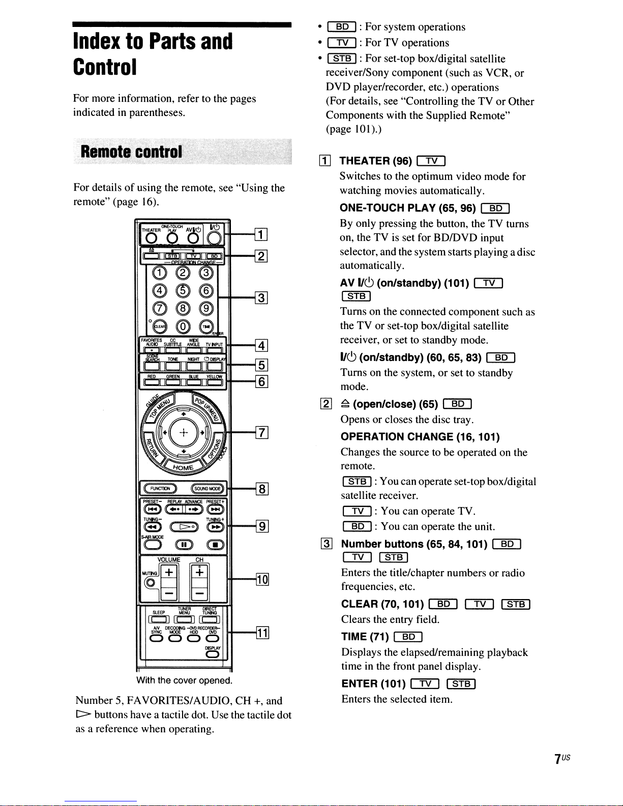
For more information, refer to the pages
indicated in parentheses.
For detailsofusing the remote, see "Using the
remote" (page 16).
FAVORfTES
CC
SUBTITlE
TOPE
101
WIlE
ANGLETVtlPUT
NIGKT
0
DlSPtA
101101
101101
HI---t
.MJOK)
~
ILJI
RED~~~
101 101
•
[§QJ:
•
CIYJ:
• I
STB
For
system operations
For
TV operations
I:
For
set-top box/digital satellite
receiver/Sony component (such as VCR,
DVD
player/recorder, etc.) operations
(For details, see "Controlling the
TVorOther
Components with the Supplied Remote"
10
(page
II]
I).)
THEATER (96)
OD
Switches to the optimum video mode for
watching movies automatically.
ONE-TOUCH PLAY
By only pressing the button, the
(65,96)
[§QJ
TV
on, the TV is set for BDIDVD input
selector, and the systemstarts playing a disc
automatically.
AV
116
I
(on/standby) (101)
STB
I
OD
Turns on the connected component such as
the
TVorset-top box/digital satellite
receiver,
116
or
set to standby mode.
(on/standby) (60, 65, 83)
[§QJ
Turns on the system,orset to standby
mode.
or
turns
TUNER
SLEEP
MENU
(CJ)
S~
0000
DE~G
TUNI'.aQ
CCD
(CJ)
~R£COR~R-
DISPlAY
U--..I
a
With the cover opened.
Number 5, FAVORITES/AUDIO,
[:::::>
buttons have a tactile dot. Use the tactile dot
as a reference when operating.
CH
+, and
[l]
~
(open/close) (65)
~
Opens or closes the disc tray.
OPERATION CHANGE (16, 101)
Changes the source tobeoperated on the
remote.
I
STB
I:Youcanoperate set-top box/digital
satellite receiver.
OD:
[§QJ
~
Number buttons (65, 84, 101)
OD
You can operate TV.
: You can operate the unit.
ISTBI
Enters the title/chapter numbersorradio
frequencies, etc.
CLEAR (70, 101)
~
OD
Clears the entry field.
TIME (71)
~
Displays the elapsed/remaining playback
time in the front panel display.
ENTER (101)
OD
I
STB
I
Enters the selected item.
~
I
STB
I
US
7
@J
AUDIO (81)
Selects the audio format/track. Opens or closes the
SUBTITLE (68)
Selects the subtitle language when multilingual subtitles are recorded on a BD- Opens or closes the BD-ROM's Pop-up
ROMlDVD VIDEO. Menu, or the
emu
emu
[l]
TOP MENU (69)
Menu.
POP UP/MENU (69)
emu
DVD's
BD'sorDVD's
emu
menu.
Top
ANGLE (68)
Switches to other viewing angles when Displays the options menu that can be
multi-angles are recorded on a
DVDVIDEO.
TV INPUT (101)
Switches the
TV and other input sources.
FAVORITES (101)
Displays the favorite channel list.
CC (101)
Changes the subtitleofthe TV.
WIDE (101)
Changes the aspect ratio
TV.
[§]
SCENE SEARCH (70)
Switches to Scene Search mode that lets
you move quickly between scenes within
the title currently being played back.
TONE (105)
Adjusts the sound by changing the
frequency envelopeofa sound.
NIGHT (105)
Activates the night mode function.
o DISPLAY (71)
Displays the playback information on the
TV screen.
Color buttons (RED/GREEN/BLUE!
rnJ
YELLOW) (85, 117)
Short cut keys for selecting items on some
BD's
menus (can also be used for
Java interactive operations).
emu
TV's
c:::!YJ
c:::!YJ
emu
emu
BD-ROMI
c:::!YJ
input source between the
em
of
the connected
emu
emu
emu
BD's
OPTIONS (65, 73, 75, 83)
selected appears on the TV screen.
HOME (60, 65, 73, 75, 83, 89, 98, 107)
emu
Enters or exits the system's home menu.
RETURN (83, 101, 117)
I
STB
Returns to the previous display.
~/~/~/~(60,65,
emu
Moves the highlight to select a displayed
item.
c:::!YJ
I
c:::!YJ
I
STB
I
emu
73,
75,83,89,98,107)
I
STB
I
e (ENTER) (60, 65, 73, 75, 83, 89, 98,
107)
emu
Enters the selected item.
GUIDE (101)
Displays the Digital Electronic Programme
Guide (EPG).
TOOLS (101)
Displays the operation menu for the current
display.
FUNCTION (60, 64, 65, 73, 75, 83, 88)
rID
c:::!YJ
c:::!YJ
c:::!YJ
I
STB
emu
Selects the playback source.
SOUND MODE (80)
Selects a suitable sound mode for movies or
music.
emu
emu
I
I
STB
c:::!YJ
I
US
8
lID
~/~
(previous/next) (65, 73, 75)
CID[] CTIJ
Skips to the previous/next chapter, track, or
of
file. To go to the beginning
track, press
PRESET
.....
+/-
(83) CID[]
twice.
Selects the preset radio station.
.../...
CID[] CTIJ I
REPLAY/ADVANCE (65)
STB
I
Replays the scenelbriefly fast forwards the
scene.
....
/~
(fast
reverselfast
73)
CID[] CTIJ I
STB
Fast reverses/fast forwards the disc when
pressed during playback.
Each time you press the button, search
speed changes.
To resume normal speed, press
TUNING
+/-
(83) CID[]
Searches the radio station.
c>
(play) (65, 73, 75) CID[] CTIJ
I
STB
I
Starts or re-starts playback.
Plays a slideshow when a disc containing
IPEG image files is inserted.
the previous
forward)
I
C:>.
(65,
[1]
SLEEP (106) CID[]
Sets the sleep timer.
TUNER MENU (86) CID[]
Enters the menu for the tuner settings.
DIRECT TUNING (86) CID[]
Selects the radio frequencies.
AN
SYNC (73)
[![]
Adjusts the delay between the picture and
sound.
DECODING MODE (77)
[![]
Selects the system's pre-programmed
decoding modes that bring exciting and
of
powerful sound
movie theaters into your
home.
DISPLAY (83)
[![]
Changes the radio informationinthe front
panel display between radio frequency and
station name.
DVD RECORDER (101) I
STB
Changes the operation mode for Sony OVO
recorders.
HOD: HOD mode
DVD: DVD mode
I
..
(pause) (65, 73, 75) CID[] CTIJ
I
STB
I
Pauses or re-starts playback.
•
I
STB
(stop)
(65, 73, 75) CID[] CTIJ
I
Stops playback and remembers the stop
point (resume point).
The resume point for a title/track
or
point you played
the last photo for a
photo folder.
S-AIR MODE (89) CID[]
Selects playback mode for the S-AIR
receiver.
11m
MUTING (65, 73, 101) CID[] CTIJ
Turn off the sound temporarily.
VOLUME
+/-
(65, 101) CID[] CTIJ
Adjusts the volume.
CH
+/-
(101) CTIJ I
STB
I
Selects the channels up and down.
is
the last
gus
,.
Front
pane':
.,
~.
~
:
...
1
IlL
\.
,
I
V
r
(
l
8 7 6 5 4 3
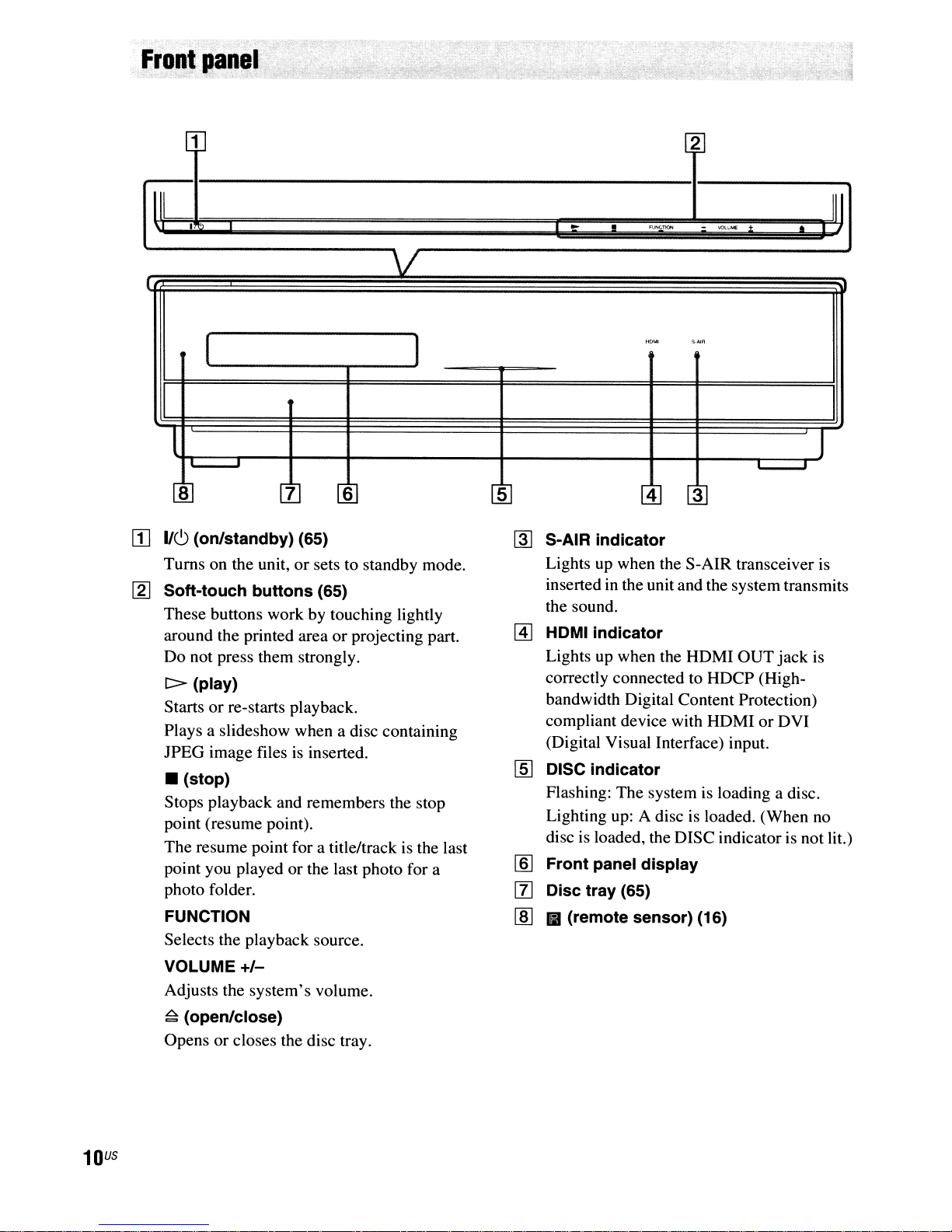
[I]
1/6
(on/standby) (65)
Turns on the unit,orsets to standby mode.
~
Soft-touch buttons (65)
These buttons work by touching lightly
or
around the printed area
Do not press them strongly.
l>
(play)
Startsorre-starts playback.
Plays a slideshow when a disc containing
lPEG
image files is inserted.
• (stop)
Stops playback and remembers the stop
point (resume point).
The resume point for a title/track is the last
point you played or the last photo for a
photo folder.
projecting part.
1
2
..
~
S-AIR indicator
Lights up when the S-AIR transceiver is
inserted in the unit and the systemtransmits
the sound.
[AJ
HDMI indicator
Lights up when the HDMI OUT
correctly connected to HDCP (High-
bandwidth Digital Content Protection)
compliant device with HDMI
(Digital Visual Interface) input.
'''''''''''
•
liO'-tl
[§] DISC indicator
Flashing: The system is loading a disc.
Lighting up: A disc is loaded. (When
disc is loaded, the DISC indicator is not lit.)
lID
Front panel display
So·AI"
-
~:,iME
or
[l] Disc tray (65)
•
jack
DVI
is
no
I I
J
III
FUNCTION
Selects the playback source.
VOLUME
Adjusts the system's volume.
~
(open/close)
Opens or closes the disc tray.
US
10
+/-
lID
III (remote sensor) (16)
About
the
indications
in
the
front
panel
display
DOD+EXDOTrueHD
DTS-HD
DTS-ES
MATRIX
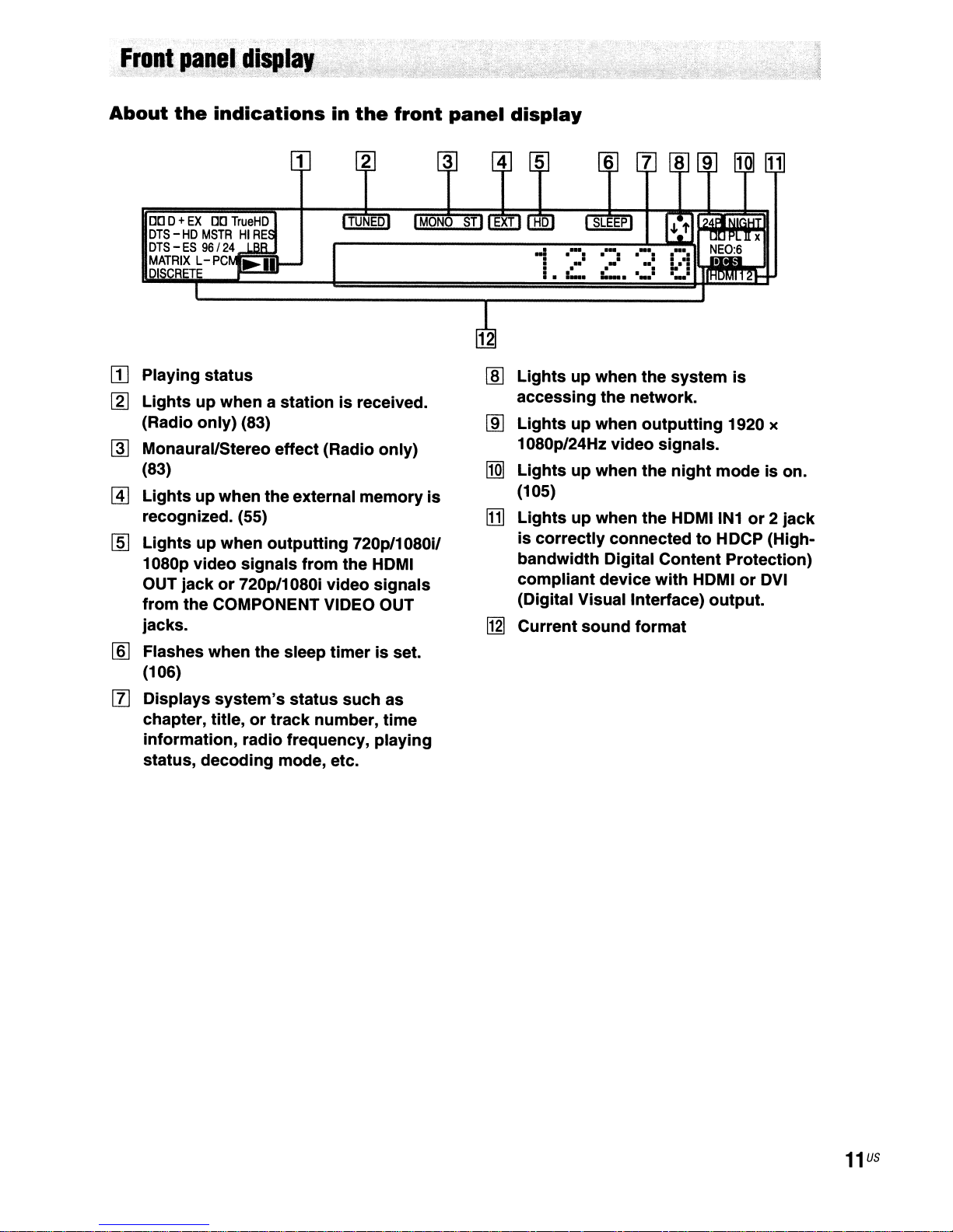
Playing
m
[gJ
Lightsupwhen a stationisreceived.
(Radio only) (83)
Monaural/Stereo effect (Radio only)
~
(83)
@]
Lightsupwhen theexternal
recognized. (55)
[§]
Lightsupwhen
1080p video signals
OUT jack
from
jacks.
Flashes when
lID
(106)
[l]
Displays
chapter, title,
information, radio frequency, playing
status, decoding mode, etc.
MSTRHIRE
96/
24
L-PC
status
outputting
from
the
or
720p/1080i video
the COMPONENT VIDEO OUT
the
system's
or
track
sleep
status
number,
timer
such as
memory
720p/1080i/
HDMI
signals
is set.
is
time
32
-!
. - -
. . . .
I.
Lights
lID
accessing the network.
Lightsupwhen
~
1080p/24Hz video signals.
Lightsupwhen
~
(105)
[1]
Lightsupwhen the HDMIIN1or2
is
correctly
bandwidth Digital Content Protection)
compliant
(Digital Visual Interlace) output.
Current
~
6 7
SLEEP
.-:
.-:
.•.:
=--
up when
sound
..
:....._.
the
system
outputting
the
night
connectedtoHDCP (High-
device
with
format
HDMIorDVI
is
1920 x
mode is on.
jack
11
us

BDV·IT1000ES
1 2 3
BDV·IS1000
1 2 3
000
SI\TfCABlE
., ,
SPEAKER
ROIl
fAOllT
WOOfIR
1
[I]
LAN (100)
terminal
(56)
[g] COMPONENT VIDEO IN (SAT/CABLE)
jacks
(50)
~
COMPONENT VIDEO OUT
@]
VIDEO OUT (VIDEO, S VIDEO)
(48)
[ID
HDMIIN1/2
rnJ
IR REMOTE (IN, OUT) (16) (BDVIT1000ES
I1J
DIGITAL IN (TV OPTICAL)
rnJ
DIGITAL IN (SAT/CABLE OPTICAL,
COAXIAL)
[ID
EZW-RT10
jacks
only)
jacks
slot
(50)
(50)
(54)
jacks
jack
(48)
jacks
(48)
WOOFS!.
[Q]
AM
terminal
[j]
FM
75Q COAXIAL
[g] HDMI OUT
~
DMPORT (DIGITAL MEDIA PORT)
(50)
IHl
A.CAL
Ml
SAT/CABLEIN(VIDEO, AUDIO R/L)
jacks
(50)
11m
TV (AUDIO IN
I1II
EXTERNAL
1m
SPEAKER
MIC
(53)
jack
jack
R1L)
slot
jacks
jack
(48)
(60, 98)
jacks
(55)
(45)
(53)
(48)
jack
US
12
Front
panel
Rear
panel
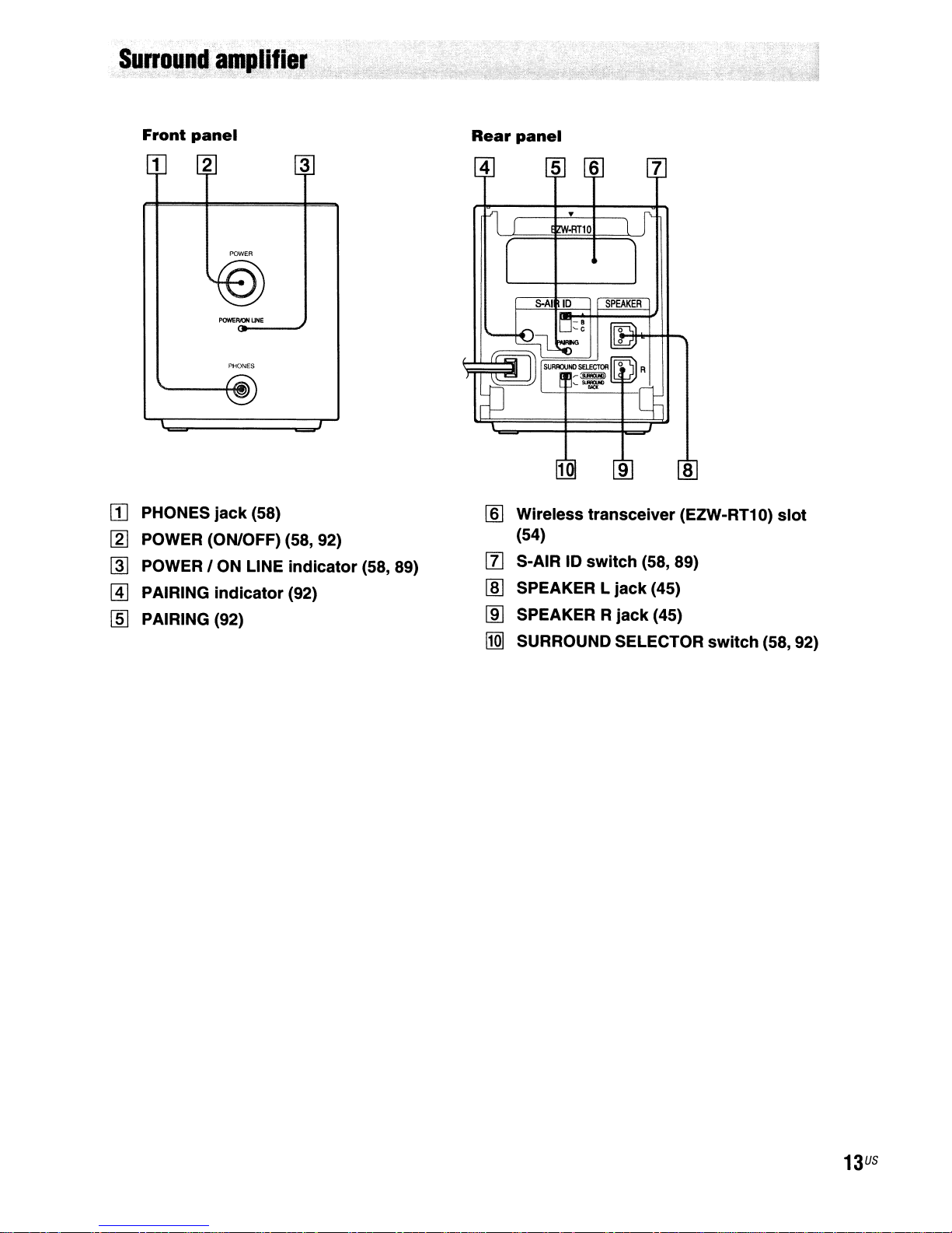
1
rn
PHONES
[ZJ
POWER (ON/OFF) (58, 92)
@I
POWER I ON LINE
@]
PAIRING
I]]
PAIRING (92)
2
POWER
POWEF/JON
PHONES
jack
indicator
UHE
(58)
3
indicator
(92)
(58, 89)
lID
Wireless transceiver (EZW-RT1 0)
(54)
[l] S-AIR 10
[ID
SPEAKER L
lID
SPEAKER R
l1QI
SURROUND SELECTOR
switch
jack
jack
(58, 89)
(45)
(45)
switch
slot
(58, 92)
13
US
Getting
Started
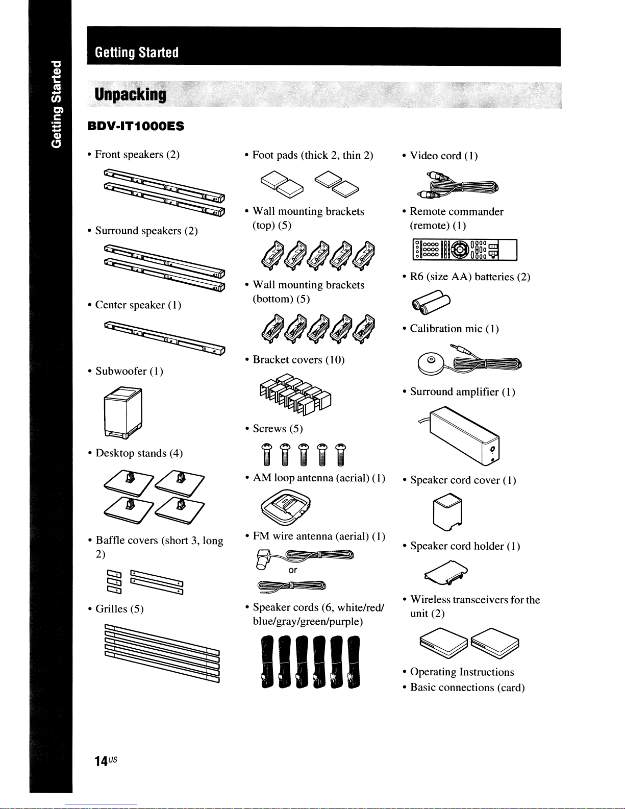
UnpC!cking
BDV·IT1000ES
• Front speakers (2)
• Surround speakers (2)
• Center speaker (I )
• Subwoofer
(I)
• Foot pads (thick 2, thin
• Wall mounting brackets
(top) (5)
• Wall mounting brackets
(bottom) (5)
• Bracket covers (10)
• Screws (5)
2)
• Video cord ( I)
• Remote commander
(remote)
~looooIIIOOOOO
o
o
• R6 (size AA) batteries (2)
• Calibration mic
• Surround amplifier (1)
0000
0000
(l)
O~Oo
~OO
(I)
• Desktop stands (4)
• Baffle covers (short 3, long
2)
~~
r.::::i]~
• Grilles (5)
iiiii
• AM loop antenna (aerial)
• FM wire antenna (aerial)
• Speaker cords (6, white/red!
blue/gray/greenlpurple)
(l)
(l)
]n
IIII11
• Speaker cord cover ( I)
• Speaker cord holder
• Wireless transceivers for the
unit (2)
• Operating Instructions
• Basic connections (card)
(I)
US
14
em
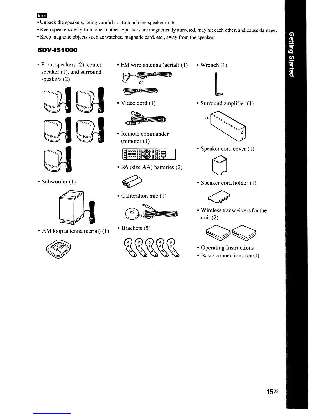
• Unpack the speakers, being careful not to touch the speakerunits.
• Keep speakers away from one another. Speakers are magnetically attracted, may hit each other, and cause damage.
• Keep magnetic objects such as watches, magnetic card, etc., away from the speakers.
BDV·IS1000
• Front speakers (2), center
speaker (
speakers (2)
• Subwoofer (I)
I),
and surround
• FM wire antenna (aerial)
£)
• Video cord (
• Remote commander
(remote)
• R6 (size AA) batteries (2)
• Calibration mic
I)
(I)
(I)
(I)
• Wrench
(I)
L
• Surround amplifier
• Speaker cord cover (
• Speaker cord holder
• Wireless transceivers for the
unit (2)
(I)
I)
(I)
• AM loop antenna (aerial)
(I)
• Brackets (5)
• Operating Instructions
• Basic connections (card)
15
US

Inserting
Insert two R6 (size AA) batteries (supplied) by matching the
markings inside the compartment.
batteries
into
the
remote
<±>
and e ends on the batteries to the
..
• Do not leave the remoteinan extremely hot or humid place.
-
• Do not use a new battery with an old one.
• Do not drop any foreign object into the remote casing, particularly when replacing the batteries.
• If you do not intend to use the remote for an extended periodoftime, remove the batteriestoavoid possible damage
from battery leakage and corrosion.
About
You can operate this system, TV, and set-top box/digital satellite receiver using the supplied remote.
Change the operation mode by using OPERA
• System operation
Press BD (BD lights up for I second).
The remote enters system operation mode, and BD lights up when you press buttons for operation.
When operating the system, point the remote at the remote sensor
• TV operation
Press TV (TV lights up for I second).
The remote enters TV operation mode, and TV lights up when you press buttons for operation (TV does
not light up when you press a button that
To operate the TV, set the remote signal to suit your TV. For details, see "Controlling the TV
Components with the Supplied Remote" (page
operation
of
the
remote
nON
CHANGE.
Gc::::JG
C'}
to
('f>
is
not available for the TV).
10
I).
II
on the unit.
or
Other
US
16
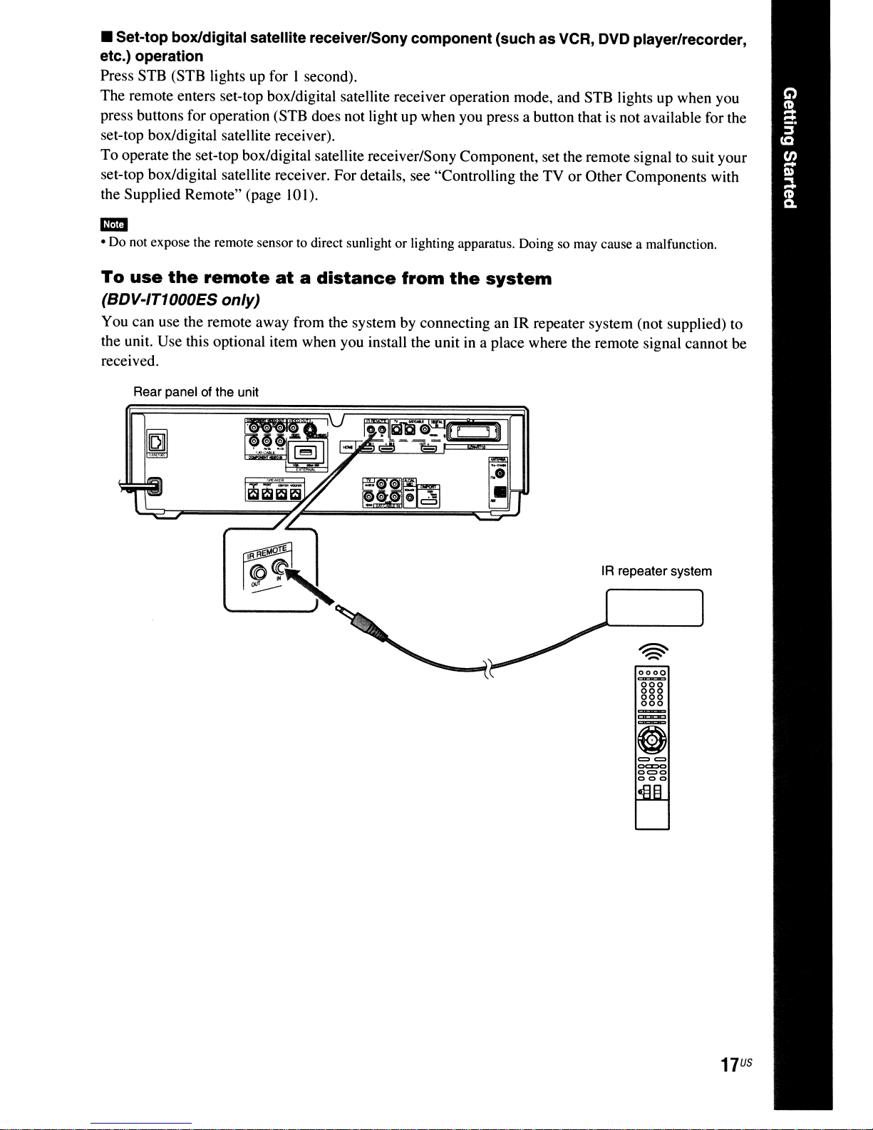
• Set-top box/digital satellite receiver/Sony component (such as VCR, DVD player/recorder,
etc.) operation
Press STB (STB lights up for I second).
The remote enters set-top box/digital satellite receiver operation mode, and STB lights up when you
press buttons for operation (STB does not light up when you press a button that is not available for the
set-top box/digital satellite receiver).
To operate the set-top box/digital satellite receiver/Sony Component, set the remote signal to suit your
set-top box/digital satellite receiver. For details, see "Controlling the TV or Other Components with
10
the Supplied Remote" (page
I).
Em
• Do not expose the remote sensortodirect sunlight or lighting apparatus. Doing so may cause a malfunction.
To
use
the
remote
(BDV-IT1000ES only)
You can use the remote away from the system by connecting an IR repeater system (not supplied) to
the unit. Use this optional item when you install the unit in a place where the remote signal cannot be
received.
Rear panel of the unit
atadistance
from
the
system
IR repeater system
0000
OO~
880
000
==
oc::co
0=0
000
17
US
Step
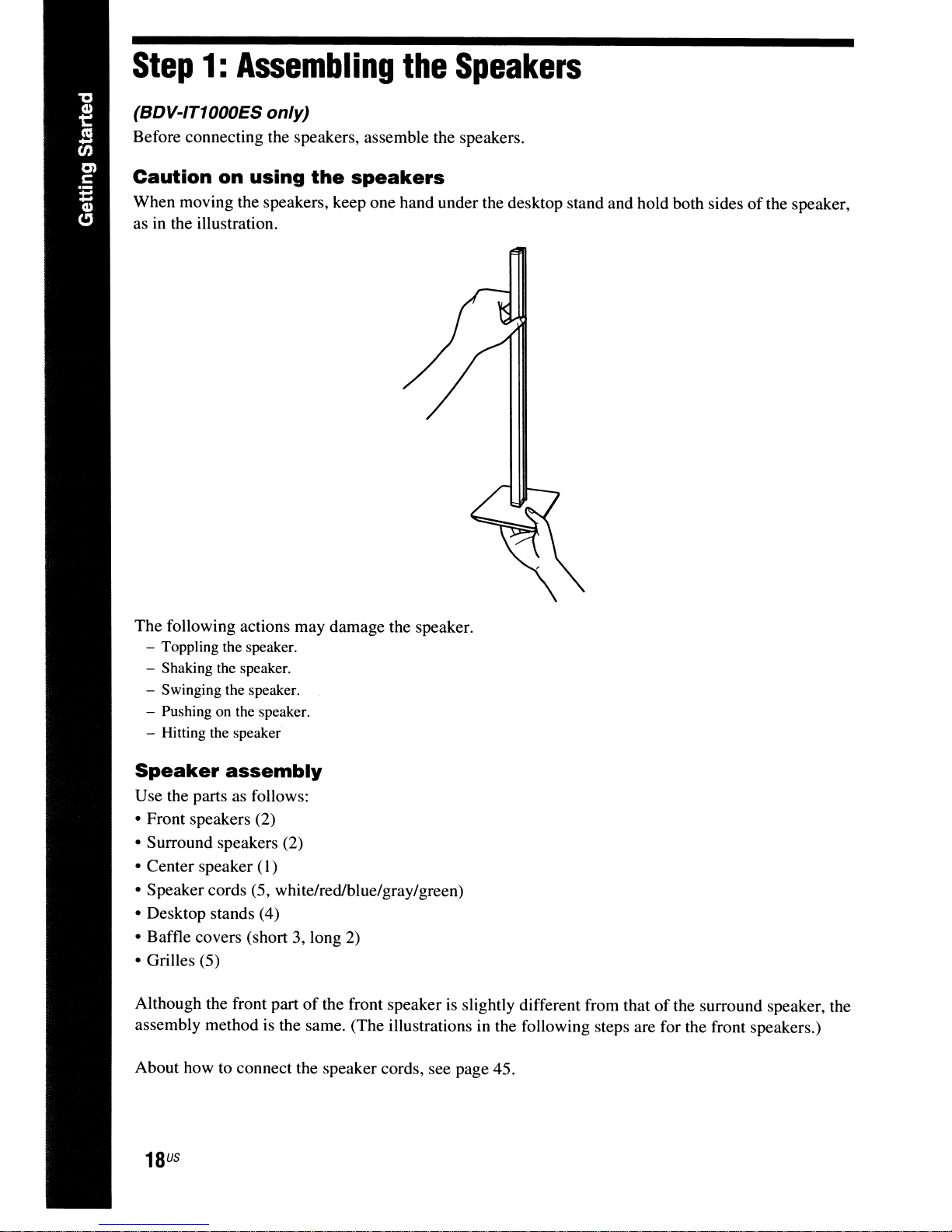
(BDV-IT1000ES only)
Before connecting the speakers, assemble the speakers.
1:
Assembling
the
Speakers
Caution
When moving the speakers, keep one hand under the desktop stand and hold both sides
as in the illustration.
The following actions may damage the speaker.
- Toppling the speaker.
- Shaking the speaker.
- Swinging the speaker.
- Pushing on the speaker.
- Hitting the speaker
on
using
the
speakers
ofthe
speaker,
Speaker
Use the parts as follows:
• Front speakers (2)
• Surround speakers (2)
• Center speaker (I)
• Speaker cords (5, white/red/blue/gray/green)
• Desktop stands (4)
• Baffle covers (short 3, long
• Grilles (5)
Although the front part
assembly method is the same. (The illustrations in the following steps are for the front speakers.)
About how to connect the speaker cords, see page 45.
US
18
assembly
of
2)
the front speaker is slightly different from thatofthe surround speaker, the
CD
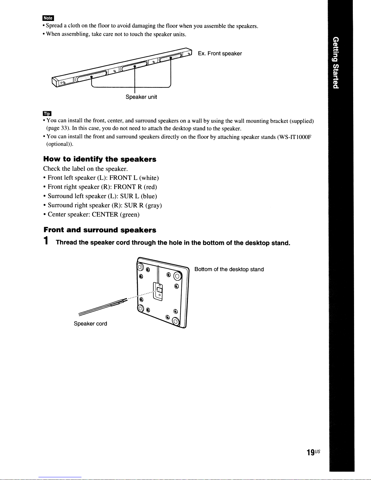
• Spread a cloth on the floor to avoid damaging the floor when you assemble the speakers.
• When assembling, take care not to touch the speaker units.
Ex.
Front speaker
Speaker unit
iir:J
• You can install the front, center, and surround speakers on a wall by using the wall mounting bracket (supplied)
(page 33).
• You can install the front and surround speakers directly on the floor by attaching speaker stands (WS-ITlOOOF
(optional».
In
this case, you do not need to attach the desktop stand to the speaker.
How
to
identity
the
speakers
Check the label on the speaker.
• Front left speaker (L): FRONT L (white)
• Front right speaker (R): FRONT R (red)
• Surround left speaker (L): SUR L (blue)
• Surround right speaker (R): SUR R (gray)
• Center speaker: CENTER (green)
Front
and
surround
speakers
1 Thread the speaker cord through the hole in the bottom of the desktop stand.
Bottom of the desktop stand
~
Speaker cord
...
19
U5
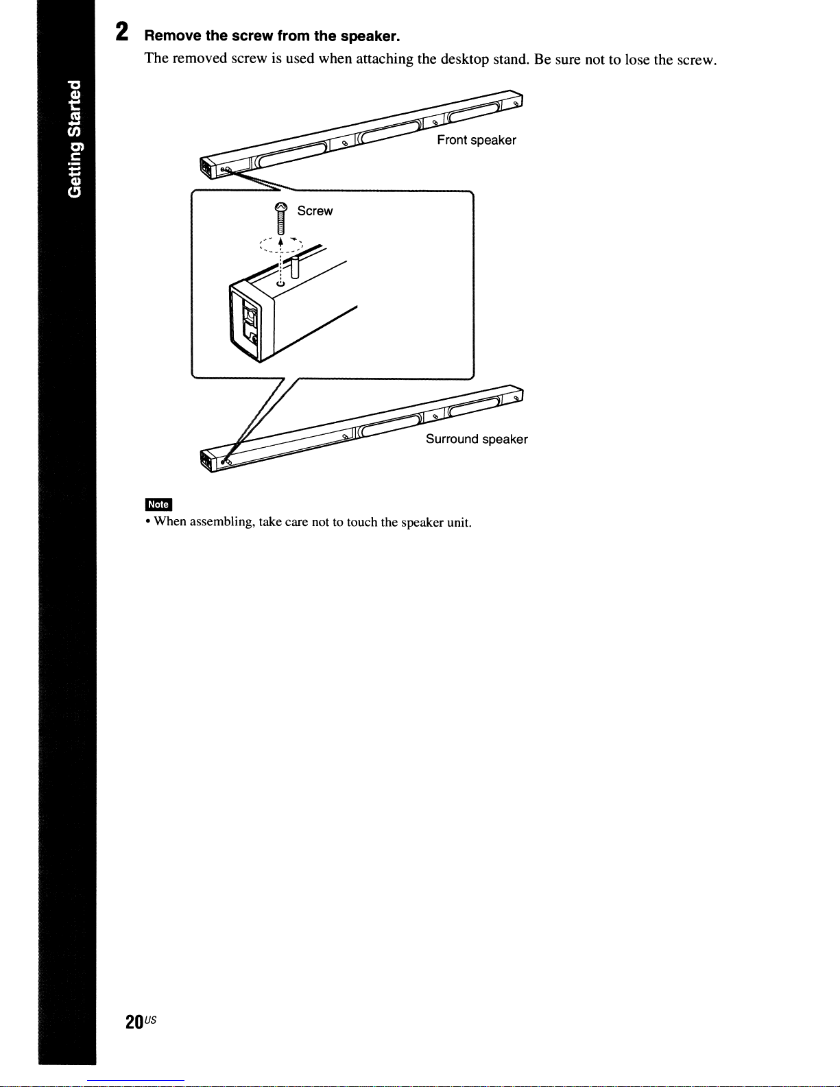
2 Remove the screw from the speaker.
The removed screw is used when attaching the desktop stand. Be sure not to lose the screw.
Surround speaker
• When assembling, take care nottotouch the speaker unit.
-
US
20
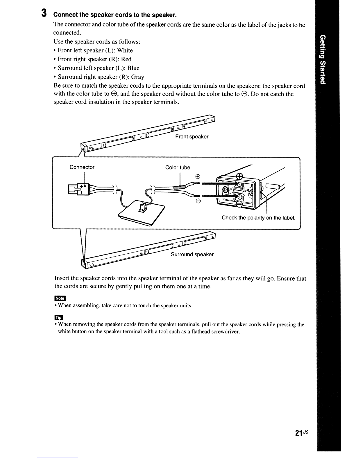
3 Connect the speaker cords to the speaker.
The connector and color tubeofthe speakercords are the same color as the labelofthe jacks to be
connected.
Use the speaker cords as follows:
• Front left speaker (L): White
• Front right speaker (R): Red
• Surround left speaker (L): Blue
• Surround right speaker (R): Gray
Be sure to match the speaker cords to the appropriate terminals on the speakers: the speaker cord
(±),
with the color tube to
speaker cord insulation in the speaker terminals.
and the speaker cord without the color tube toe.Do not catch the
Connector
Insert the speaker cords into the speaker terminalofthe speaker as far as they will go. Ensure that
the cords are secure by gently pulling on them one at a time.
• When assembling, take care not to touch the speaker units.
-
iii!
• When removing the speaker cords from the speaker terminals, pull out the speaker cords while pressing the
white button on the speaker terminal with a tool such as a flathead screwdriver.
Color tube
Check the polarityonthe label.
21
us
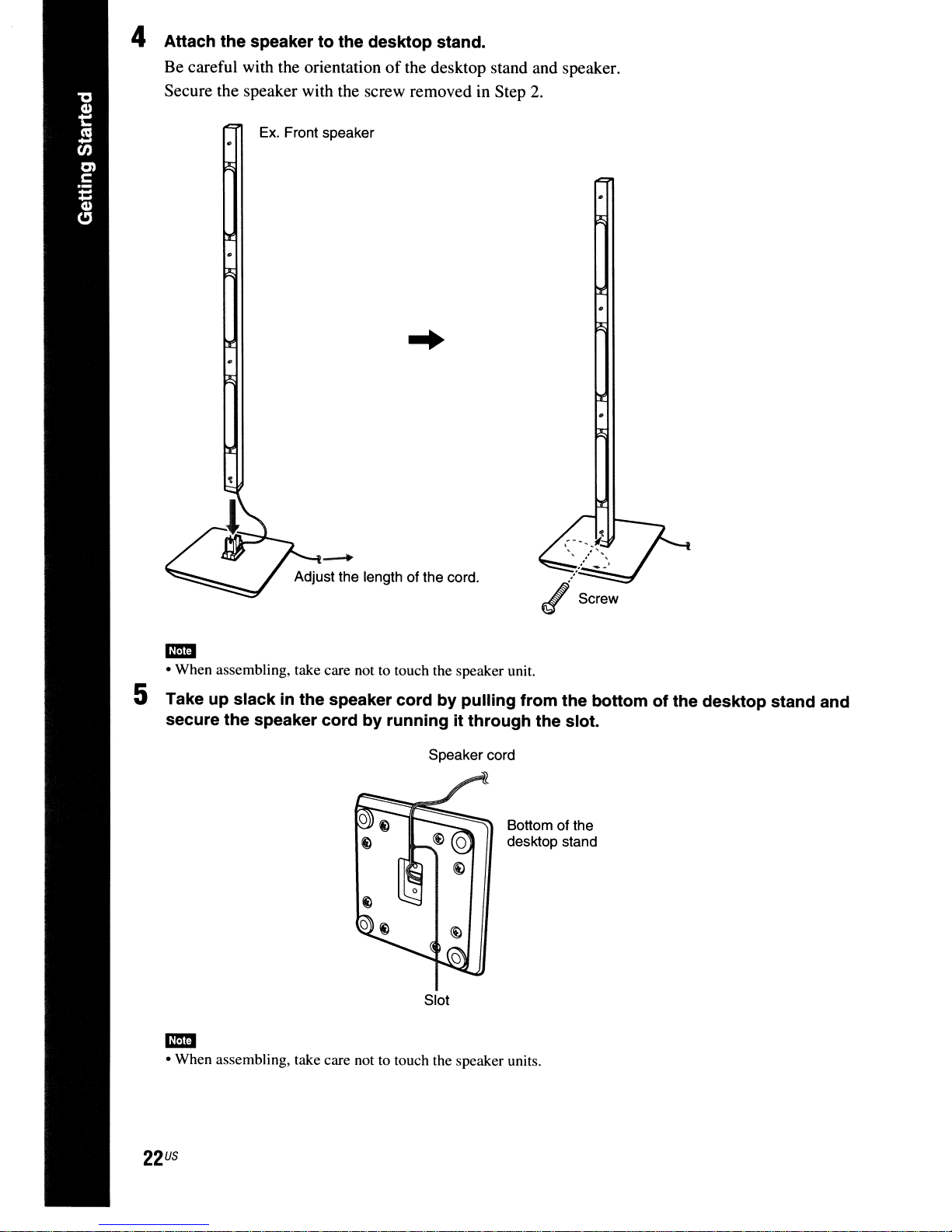
4 Attach the speaker to the desktop stand.
Be careful with the orientationofthe desktop stand and speaker.
Secure the speaker with the screw removed in Step 2.
Ex.
Front speaker
.-...
Adjust the length of the cord.
mil
• When assembling, take care not to touch the speaker unit.
5 Take up slack
secure the speaker cord
in
the speaker cord by pUlling from the bottom of the desktop stand and
by running it through the slot.
Speaker cord
Slot
Bottom of the
desktop stand
mil
• When assembling, take care not to touch the speaker units.
US
22
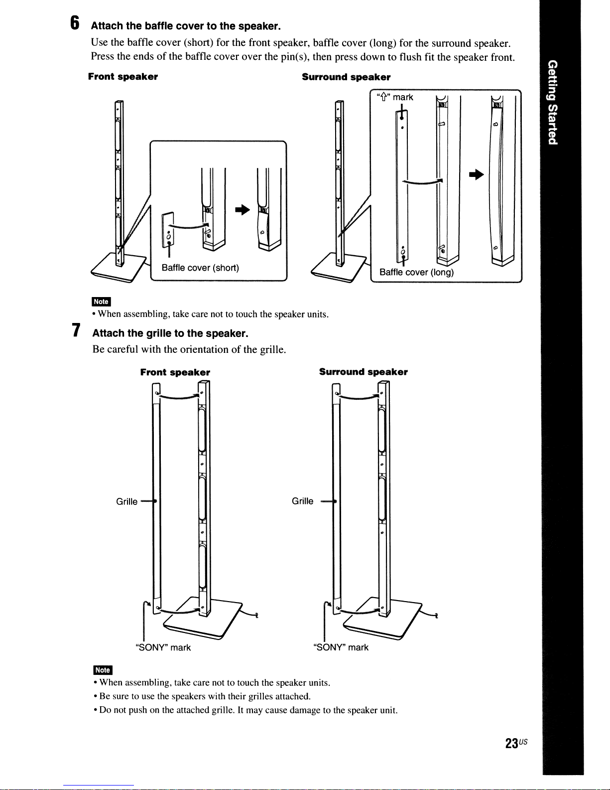
6 Attach the baffle cover to the speaker.
Use the baffle cover (short) for the front speaker, baffle cover (long) for the surround speaker.
of
Press the ends
Front
speaker
the baffle cover over the pin(s), then press down to flush fit the speaker front.
Surround
speaker
"'fr"
mark
..
Baffle cover (short)
• When assembling, take care not to touch the speaker units.
-
7 Attach the grille to the speaker.
Be careful with the orientationofthe grille.
Front
speaker
Surround
-
.
o e
Baffle cover (long)
speaker
..
Grille
"SONY" mark
• When assembling, take care not to touch the speaker units.
-
• Be sure to use the speakers with their grilles attached .
• Do not push on the attached grille.
Grille
"SONY" mark
It
may cause damage to the speaker unit.
23
US
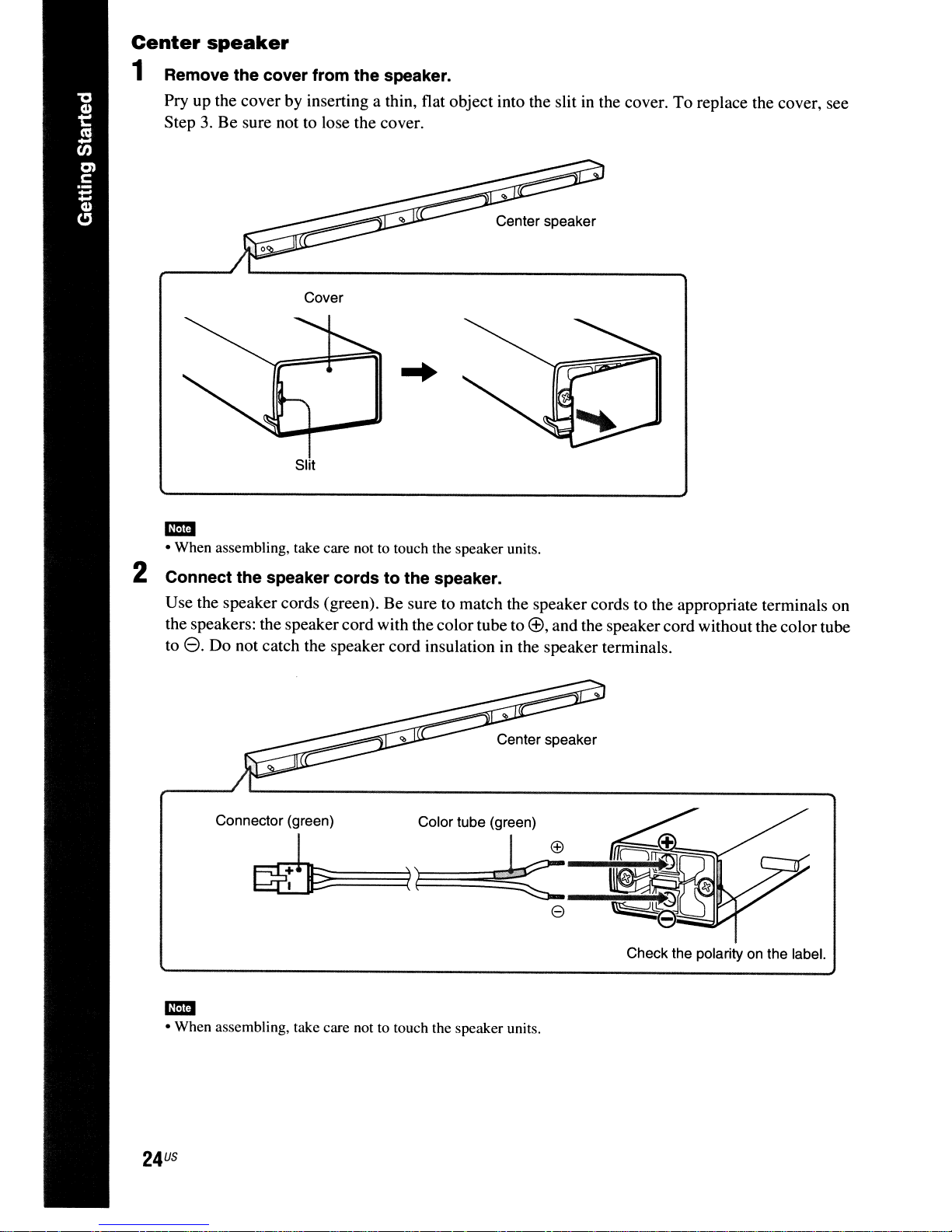
Center
speaker
1 Remove the cover from the speaker.
Pry up the cover by inserting a thin, flat object into the slit
Step
3.
Be sure not to lose the cover.
Center speaker
Cover
in
the cover. To replace the cover, see
mmI
• When assembling, take care not to touch the speaker units.
2 Connect the speaker cords to the speaker.
Use the speaker cords (green). Be sure to match the speaker cords to the appropriate terminals on
l±),
the speakers: the speaker cord with the colortube to
e.
Do not catch the speaker cord insulation in the speaker terminals.
to
Center speaker
Connector (green) Color tube (green)
~====:::::(n~i
~~-k:~O""M'
and the speaker cord without the colortube
EEl
----'~~(
e
Check the polarityonthe label.
mmI
• When assembling, take care not to touch the speaker units.
US
24
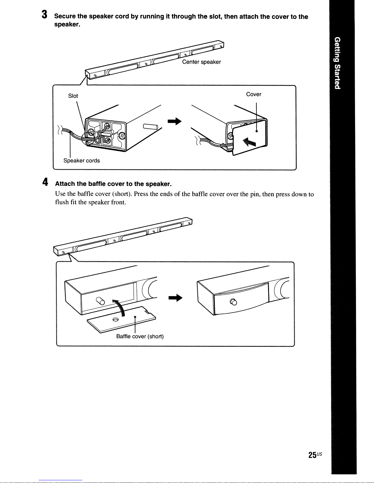
3 Secure the speaker cord by running it through the slot, then attach the cover to the
speaker.
Slot
Speaker cords
Cover
4 Attach the baffle cover to the speaker.
Use the baffle cover (short). Press the endsofthe baffle cover over the pin, then press down to
flush fit the speaker front.
Baffle cover (short)
25
US
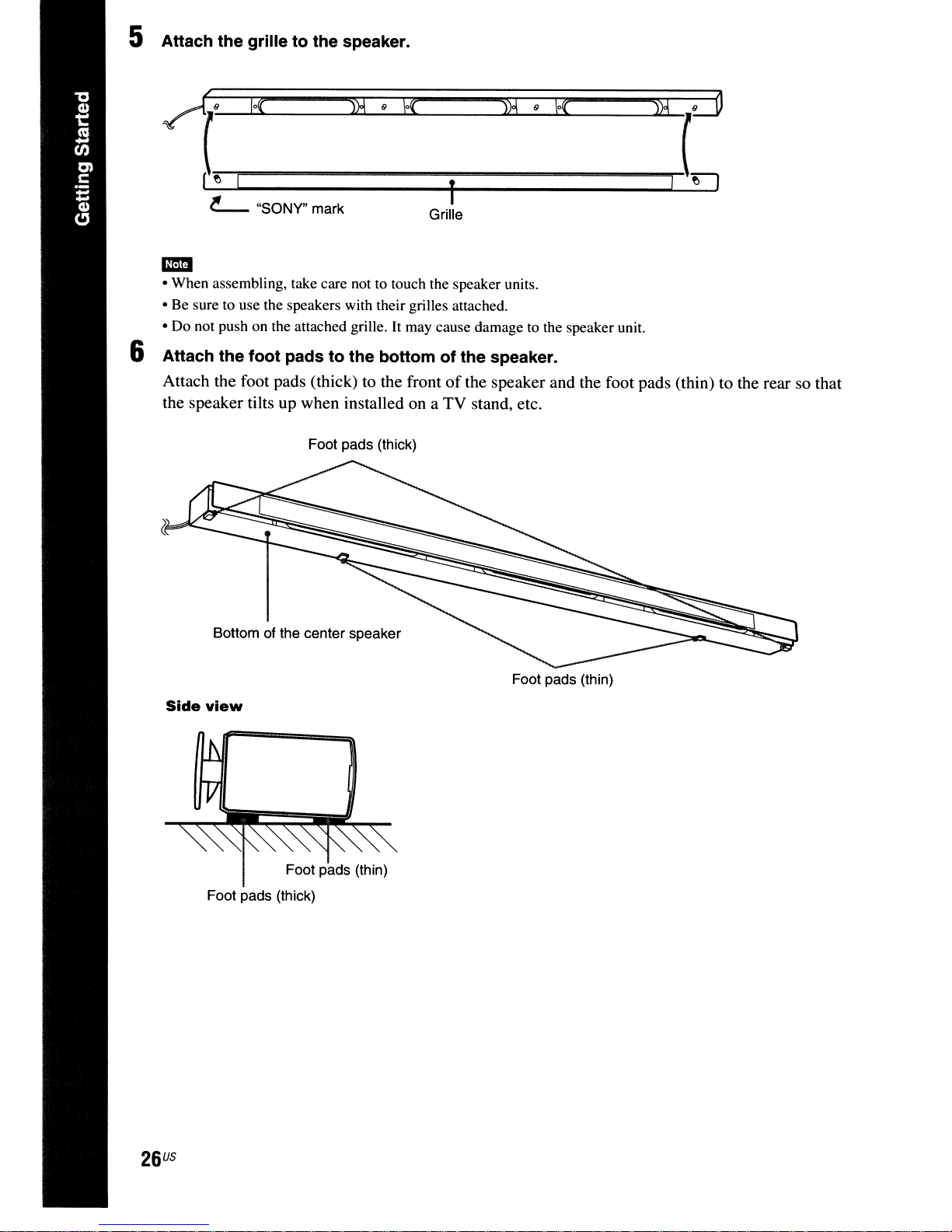
5 Attach the grille to the speaker.
~uo(
'--~·---lo'_----f-
~
"SONY" mark Grille
--,,)2...L...-9;.......J,f~{
),"-2"""""';'9--l.\O(JIoo...
"""')"-l2_
.....
L
d
mm
• When assembling, take care not to touch the speaker units.
• Be sure to use the speakers with their grilles attached.
• Do not push on the attached grille.
It
may cause damage to the speaker unit.
6 Attach the foot pads to the bottom of the speaker.
Attach the foot pads (thick) to the frontofthe speaker and the foot pads (thin) to the rear so that
TV
the speaker tilts up when installed on a
Foot pads (thick)
stand, etc.
Bottom of the center speaker
Side
view
Foot pads (thin)
Foot pads (thick)
Foot pads (thin)
US
26
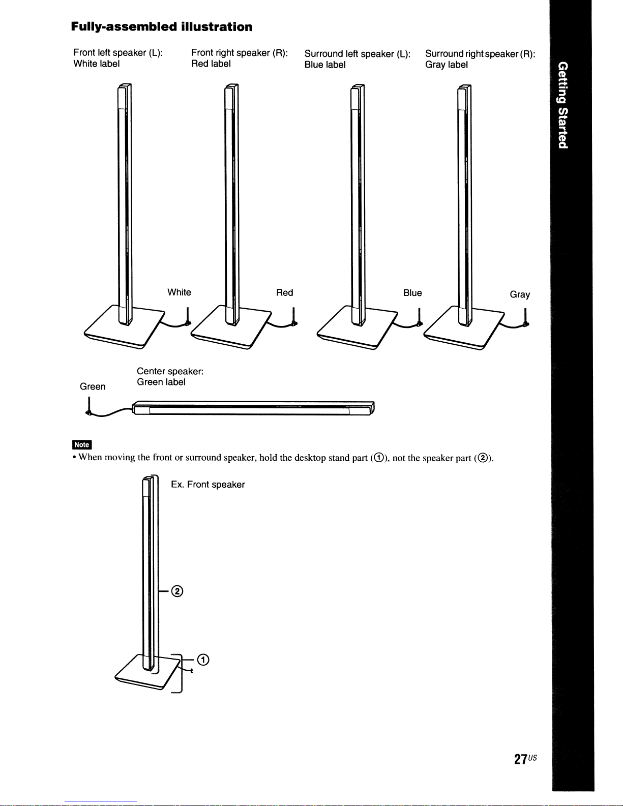
Fully-assembled
illustration
Front left speaker
White label
(L):
Front right speaker
Red
label Blue label Gray label
White
(R):
Red
Surround left speaker
(L):
Surround rightspeaker
Blue Gray
(R):
Center speaker:
Green
• When moving the front or surround speaker, hold the desktop stand part
-
Green label
11"11
H-..:::::t_
Ex.
Front speaker
CD
<G)),
not the speaker part
<@).
27
US
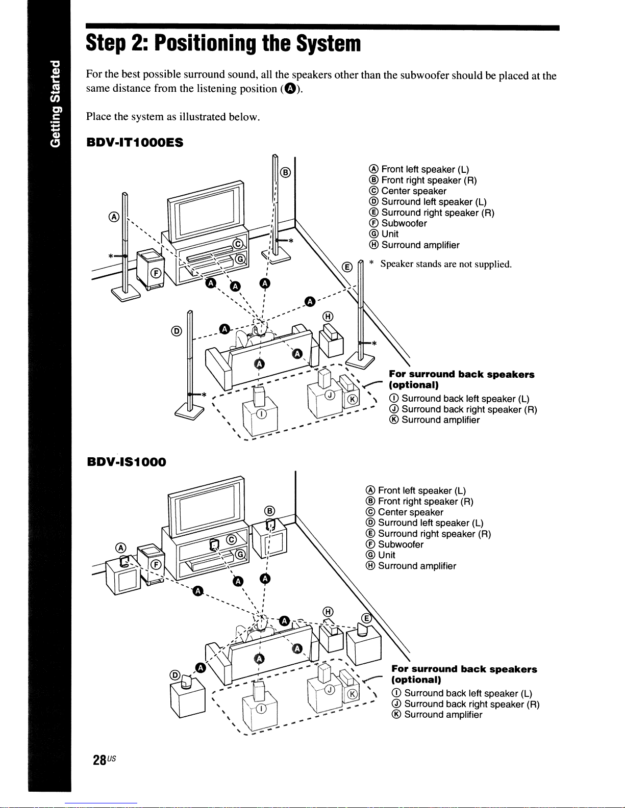
Step
For the best possible surround sound, all the speakers other than the subwoofer should be placed at the
same distance from the listening position
Place the system as illustrated below.
BDV·IT1000ES
2:
Positioning
the
(0).
System
BDV·IS1000
@
* ;
......
""_Q)-
,
,I
\.;
"
..
,......
®I-
....
-"
@
..
.......
@ Front left speaker (L)
® Front right speaker (R)
© Center speaker
@ Surround left speaker (L)
® Surround right speaker (R)
® Subwoofer
@Unit
® Surround amplifier
* Speaker stands are not supplied.
"""
........
..
,
'r-@'®"\CDSUrrOundbaCkleftspeaker(L)
.. .. ......
. "
'..
,
..
-
~...,,--
......
..
For
surround
(optional)
Q) Surround back.r!ght speaker (R)
® Surround amplifier
-
back
speakers
28
US
@ Front left speaker (L)
® Front right speaker (R)
© Center speaker
@ Surround left speaker (L)
® Surround right speaker (R)
® Subwoofer
@Unit
® Surround amplifier
For
surround
(optional)
CD
Surround back left speaker (L)
Q) Surround back right speaker (R)
back
speakers
® Surround amplifier
-"
About
You can enjoy
surround amplifier (optional). Use the commercially available speakers for the surround back speakers.
To use the surround amplifier for the surround back speakers, connect the surround back speakers (not
supplied) to the surround amplifier, see "Using an S-AIR Product" (page 89).
• Avoid placing obstructions around the speaker.
-
• After installing the speakers, arrange the speakercordsso as not to topple the speakers by catchingthe speaker cords
with your foot.
• Avoid placing the center speaker on the TV.
• Do not set the speakers
• Avoid placing the speakers
- Extremely hot
- Dusty
- Very humid
- Subject to vibrations
- Subject to direct sunlight
• Use caution when placing the speakers and/or speakerstands attached to the speakers on a specially treated (waxed,
oiled, polished, etc.) floor, as staining
• Do not use any type
• Do not lean or hang on the speaker. as the speaker may fall down.
• Do not bend, twist, or fold the speaker grille. (BDV-ITI
• Do not insert
• Avoid placing the speakers close to a CRT-based TV.
• When using the optional stand, we recommend that the speakers are installed on a flat and firm floor (not on a thick
pile carpet, for example). The speakers may topple over
the
or
dirty
an
surround
7.1
surround sound with the surround back speakers by purchasing the additional
or
cold
of
object (especially metal) into a hole on the front partofthe speaker. (BDV
back
inaninclined position.
in
locations that are:
abrasive pad, scouring powder,orsolvent such as alcoholorbenzine.
speaker
or
discoloration may result.
OOOES
It
may cause color irregularity. (BDV-ITlOOOES only)
if
only)
installed on an inclinedorsoft floor.
-ITIOOOES
only)
iir:I
• When you change the positionsofthe speakers, Sony recommends that you change the settings. For details, see
"Calibrating the Appropriate Settings Automatically" (page 98) and "Setting the Speakers" (page 100).
29
US
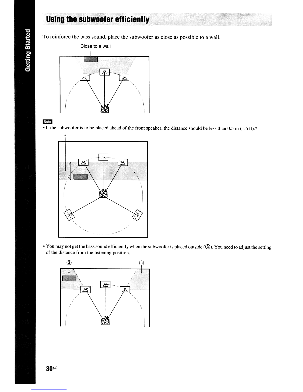
U.ing
To reinforce the bass sound, place the subwoofer as close as possible to a wall.
.••
·....,
..
~u~w.ofer;efliciently·
Close to a wall
• If the subwooferisto be placed ahead
-
*
• You may not get the bass sound efficiently when the subwoofer is placed outside
of
the distance from the listening position.
3
of
the front speaker, the distance should be less than 0.5 m (1.6 ft).*
3
(@).
You need to adjust the setting
US
30
 Loading...