

Sony BDV-E770W / T77, BDV-E770W, BDV-T77 Operating Instructions Manual

SONY
4-178-242-12(
1)
...,...-......---
TM
S/u-ragD;sc
Blu-ray Disc/DVD
Home Theatre System
Operating Instructions
BDV-E770W/T77
©2010 Sony Corporation
WARNING
To reduce the risk of fire
or electric shock,
expose this apparatus
rain or moisture.
Do
not
in,tall the appl iance
confined space. such as a bookcase
or built-in cabinet.
To reduce the risk
coverthe ventilation openingofthe
apparatu, with nev'.'paper,.
tablecloths. curtains. etc. Do not
place the naked tlame sources such
as lighted candles on the apparatus.
To reduce the risk
shock. do not expose this apparatus
to dripping
place objects filled with liquids,
such as vases, on the apparatus.
Do not expose batteries or
apparatus with battery-installed to
excessive heat such as sunshine,
fire
To prevent injury. this apparatus
must
floor/wall
installation instructions.
Indoor use only.
or ,plashing. and do not
or
the like.
be
securely attached to the
in
accordance with the
CAUTION
The useofoptical instruments with
this product will increase eye
hazard. As the laser beam used
this Blu-ray Disc / DVD Home
Theatre System
do not attempt to disassemble the
cabinet.
Refer servicing to qual ified
personnel only.
This appliance
CLASS 3R LASER product.
Visible and invisible laser radiation
is
emitted when the laser protecti
is
is
do
not
ina
of
fire. do
of
fire or electric
harmful to eyes.
classified as a
not
to
in
ve
illlusi
n~
h opened.
avoid direct eye exposure.
This marking
protective housing inside the
enclosure.
CLASS 1 LASER PRODUCT
LUOKAN 1 LASERLAITE
KLASS 1 LASERAPPARAT
This applianceisclassified as a
CLASS I LASER product.
markingis
exterior.
located
,I)
he
,lire
is
located on the laser
Thi,
Oil
the rear
[(l
Precautions
On
power
• The unitisnot disconnected from
the mains as long as
connected to the AC outlet. even
if the unit itself has been turned
off.
• As the main plug
disconnect the unit from the
mains. connect the unit to
easily accessible AC outlet.
Should you notice
in
the unit. disconnect the main
plug from the AC outlet
immediately.
These following indications are
located on the rear exterior.
~
ili
"dangerous voltage" within the
product's enclosure that may
sufficient magnitudetoconstitute a
ri,k
of
JI\
ill
• presence
nperating and maintenann'
(servicing) instructions
literature accompanying the
appliance.
sources
it
is
is
used to
an
an
abnormality
This symbolisintended to
alert the usertothe
of
presence
electric shocktopersons.
This symbolisintended to
alert the user to the
ulllnsulated
of
important
in
be
the
Owner's
The model alld serial Ilumber, arc
located at the rear exterior
control unit. Record the serial
number
Ixlow. Rel'cr
call upon your Sony dealer
regarding this product.
!\1odel
T77
Serial No
The following FCC statement
applie, only
model manufactured for sale
U.S.A. Other versions lllay
comply with FCC technical
regulations.
NOTE:
This equipment has been tested and
found
a Class
15
Part
limits are designed to provide
reasonable protection agai nst
harmful interference
installation. This equipment
generates, uses, and can radiate
radio frequency energy and. if not
installed and used
with the instructions. may cause
harmful interference
communications. However. there
no guarantee that interference will
not
occurina particular
in,tallarion. If thi, equipment does
cause harmful interference to radio
or television reception. which can
be
determinedbyturning the
equipment
encouraged to trytocorrect
interferencebyone or more of the
of
following mea,ures:
- Reorient or relocate the recei\i
antenna (aerial).
- Increase the separation hetween
the equipment and receiver.
Connect the equipment into
outlet on a circuit
that to \vhich the rel'el\
connected.
- Consult the dealer or
experienced radio/TV technician
for help.
Record
of
the
in
the space provided
tll
thcm\\hene\er\
No.
BDV-F770W/BI)V
to
thc
\ehillnofthi'
in
not
to
comply with the limits for
B digital device. pursuant to
of
the FCC Rules. These
in
a residential
in
accordance
to
radio
off
and on. the user
the
an
ditler~'nt
an
cr
frolll
I,
llll
the
is
i,
ng
US
2
CAUTION
You are
or modifications not expressly
approved in this manual could void
your authority to operate this
equipment.
Important
cautionedthat
Safety
any changes
Instructions
1)
Read these instructions.
2) Keep these instructions.
3) Heed all warnings.
4) Follow all instructions.
5) Do not use this apparatus near
water.
6) Clean only with dry cloth.
7) Do not block any ventilation
openings. Install in accordance
with the manufacturer's
instructi ons.
8) Do not install near any heat
sources such as radiators, heat
or
registers, stoves,
apparatus (including
amplifiers) that produce heat.
9) Do not defeat the safety
of
purpose
grounding-type plug. A
polarized plug has two blades
with one widerthan the other. A
grounding type plug has two
blades and a third grounding
prong. The wide blade or the
third prong are provided for
your
plug does not fit into your
outlet, consult an electrician for
replacement
outlet.
10)
Protect the power cord from
being walked on
particularly at plugs,
convenience receptacles, and
the point where they exit from
the apparatus.
II)
Only use attachments/
accessories specified by the
manufacturer.
12)
Use only with the cart, stand,
tripod, bracket,
specified by the manufacturer,
or sold with the apparatus.
When a cart is used, use caution
when moving the cart/
the polarized or
safety.Ifthe provided
other
of
the obsolete
or
pinched
or
table
apparatus combination to avoid
injury from tip-over.
13) Unplug this apparatus during
or
lightning storms
unused for long periods
14) Refer all servicing to qualified
service personnel. Servicing is
required when the apparatus
has been damaged in any way,
such as power-supply cord
plug is damaged, liquid has
been spilled or objects have
fallen into the apparatus, the
apparatus has been exposed to
rain or moisture, does not
operate normally,
dropped.
ENERGYSTAR®
is
mark.
Ij~i§;J4i'4;1
•
Sony Corporation has determined
that this product meets the
ENERGY
energy efficiency.
For
the
As an
STAR® partner,
STAR® guidelines for
wireless
transceiver
when
of
time.
or
or
has been
a U.S. registered
ENERGY
(EZW·
RT1O/EZW·RT1OA)
This equipment must not be co-
in
located or operated
with any other antenna or
transmitter.
This equipment
radiation exposure limits set forth
for uncontrolled equipment and
meets the FCC radio frequency
(RF) Exposure Guidelines
Supplement C to OET65.
This equipment should be installed
and operated with at least 20cm and
more between the radiator and
person's body (excluding
extremities: hands, wrists, feet and
ankles).
conjunction
complies
with FCC
in
For
the
LAN
USB
Adapter
Wireless
(UWA.
BR100)
Pursuant to FCC regulations, you
indoors
and
band for
em
your
body
or
(or
are cautioned that any changes
modifications not expressly
in
approved
your authority to operate this
equipment.
To prevent radio interference to the
licensed service, this device is
intended to be operated indoors and
away from windows to provide
maximum shielding.
its transmit antenna) that is
installed outdoors
licensing.
Only use Wireless
when using it with IEEE 802.11 a
(5
GHz).
High power radars are allocated as
primary users (meaning they have
priority)
5650-5850
could cause interference and/or
damage to this device.
This device uses 5
wireless LAN communication and
the maximum gain
this device is 5 dBi.
This equipment complies with
FCC/IC radiation exposure limits
set forth for an uncontrolled
environment. This equipment
should be installed and operated
with minimum distance 20
between the radiator and
(excluding extremities: hands,
wrists and feet).
This device and its antenna(s) must
not be co-located or operating with
any other antenna or transmitter
except Grant condition.
Ifyou have any questions about this
product, contact Sony
Information Service
800-222-7669orvisit http://
www.sony.com/on
The telephone number
FCC-related matters only.
Regulatory Information
this manual could void
Equipment
is
subject to
LAN
of
5250-5350
MHz
MHz
and these radars
GHz
of
the antenna
Customer
Centerat1-
the Internet.
belowisfor
in
US
3
Declaration
of
Conformity
Trade Name: SONY
Model
UWA-BR
100
Responsihle Partv: Suny
EllxtruniL"I
IlL
Address: 16530 Via Fsprillo.
San Diego.
Teleph(lnc
22.~()
This
C\
~umher
de\
ICC
Clllllplie, \\ilh p,lrl
'12127
LS.A.
~."X-')--I2
15ofthe FCC rules. Operation
subjeCl to Ihe foIIO\\'ing t\\U
conditions:
I I ) This
de\ice
m,l)
not cause harmful interference.
(2)
and
this dC\'ice must accept
any interference received.
including interference that may
cause undesired operation.
Copyrights
and
Trademarks
• This product incorporatcs
copyright protection technology
is
protected hy U.S. patents
that
and other intellectual property
rights.
of
this copyright protection
Use
technology must be authorized by
is
MacHl\'ision. and
home and other limited vieviing
uses only unless otherwise
authorized hy Macrovision.
Reverse engineering or
disassemhly
is
• This system incorporates with
Dolby~'
Logic
Digital and Dolh) Pro
([J)
adaptive matrix
surround decoder and the DTS
Digital Surround System.
",
Manufactured under license
from Dolby Laboratories.
Dolby. Pro Logic. and
double-D symbol are
trademarks
Laboratories.
"'"
Manufactured under liccn,e
under U.S. Patent #'s:
5.451.942: 5.956.674:
5,974.380: 5.978.762:
6,226.616: 6.487.535:
intended for
prohihited.
of
Dolhy
~Ii
is
"""
th~'
7..".12.195: 7.272.567
other U.S. and \\orld\\ ide
patent, issued & pending.
is
DTS
a registered
trademark and the DTS
logos. Symbol. DTS-HD
,illd DTS-HD l\lastcr Audit'
of
are trademarks
\D
1'1l)6-2{){)X
DTS. Inc.
DTS. Inc.
Rights Reserved.
• This
,ystem
incorporates HighDefinition Multimedia Interface
(HDMrr\l) technology.
HDMI.
HDMllogo
and High-
111l'
Definition Multimedia Interface
or
an: trademarks
trademarks
registered
of
HDMI Licensing
LLC.
• Ja\'a and all
Ja\a-based
trademarks and logos are
trademarks or registered
of
trademarks
Sun Microsystems.
Inc.
•
"BD-LIVE"
"BONUSVIEW"
of
Blu-ray Disc Association.
• "Blu-ray Disc"
• "Blu-ray Disc."
"DVD-RW:'
"DVD
R."
and
arc trademarks
is
a trademark.
"DVD+RW:'
"DVD+R:'
VIDEO:'
and
"DVD-
"CD"
logos are trademarks.
•
"BRA
VIA"isa tradcmark
of
Sony Corporation.
VCHD"
• "A
logo are trademarks
Electric Industrial
and the"AVCHD"
of
Matsushita
Co..Ltd. and
Sony Corporation.
"S-AIR"
•
trademarks
•
'~'"
bar" are trademarks
and its logo are
of
"XMB:'
Sony Corporation.
and "xross media
of
Sony
Corporation and Sony Computer
Entertainment Inc.
•
"PLA
YSTA
TION"isa trademark
uf
Sony Computer Entertainmcnt
Inc.
• Music and
\ideo
recognition
tcchnology and related data are
pn)\idedbyGracenote@
is
Gracenote
in
music recognition technology
the industry stanclard
and related content delivery. For
more information, please visit
www.gracenote.com.
«:
All
('I).
D\I).
BllI-I:ty
music and \ ideo-related d"t:t I
Graccnlltc. Inc..copyright
I)I~C
and
I'll
(j")
2()(){)-present Gracenutc.
Gracenutc Soft
2()()()-pre'L'nl
"arc.
cupyright
(J1':I,'I'IIUlL'
On,'
III'
more patents owned hy Gracenotc
"ppl) to this pnxlucl
See the
Gr:lC~'notc
npnexh,lllsti\ c
lislllf
:ll1d
\\
ehs
ite
applicahk'
sel"l
I'm
ic,'.
a
Graeenote patents. Gr:tcenote.
CDDB. MusiciD. i\1cdiaVOCS.
tilL'
Gr<lCL'nO(L
and the "PIl\\cred
logo arc
trademarks
Gracenote
logu
L'itlwr
rcgi,tered
or
trademarks of
in
lhe United State,
<lnL!
logol) pl'.
hy
(iracenolC"
and/or other countries.
!gracenote
• "PhotoTV HD" and the "PhOIOTV
HD"
logo are trademarks of Suny
Corporation.
• MPEG Layer
technology and patents licensed
from Fraunhofer liS and
Thomson.
is
• iPod
registeredinthe U.S. and other
countries.
• "Made for iPod" means that
electronic accessory has been
designed
to iPod and has heen certified
the developer to meet Apple
performance standards.
• Apple
is
operation
compliance with safety and
regulatory standards.
• Other system and product names
are generally trademarks
registered trademark,ofthe
manufacturers.
are not indicated
~
audio coding
a trademarkofApple
to
connect ,pecifically
not responsible for the
of
this de\'ice
or
or
1"\1 and @ mark,
in
this docuillent.
Inc
an
bv
its
III
~)
..
US
4
About
These
Operating
Instructions
• The instructions in these
Operating Instructions
describe the controls on the
remote. You can also use the
controls on the unit if they
have the same or similar
names as those on the remote.
In
this manual, "disc"isused
•
as a general reference for
BOs, OYOs, Super Audio
or
COs,
specified by the text or
illustrations.
• The instructions in this
manual are for BOY-E770W
and BOY-T77. BOY-E770W
is the model used for
illustration purposes. Any
difference
clearly indicated in the text,
for example, "BOVE770W."
• The items displayed on the
TY screen may vary
depending on the area.
• The default setting is
underlined.
• The system is compatible
with the S-AIR function,
which allows transmission
sound between S-AIR
products wirelessly. For
details on theS-AIR function,
see "Using an S-AIR
Product" (page 39).
• Notes or instructions for the
surround amplifier, surround
back amplifier,
receiver
Instructions refer only to
when the surround amplifier,
surround back amplifier, or
S-AIR receiver is used.
COs unless otherwise
in
operation is
or
S-AIR
in
these Operating
of
US
5
Table
of
Contents
About
Unpacking..
IndextoParts
Getting
These
Started
Operating
and
Control
Instructions 5
Step1:Installing the System 14
Step
2:
Connecting the System 17
Step
3:
Setting up the
S-AIR Wireless System 24
Step
4:
Performing the Easy
Setup 25
5:
Step
Step
Selecting the Source 26
6:
Enjoying Surround
Sound 27
Playback
PlayingaDisc
Playing
EnjoyinganiPod
Playing
Available
Sound
Selecting
Selecting
Enjoying
Using the
from
a USB
via a
Network
Options
Adjustment
the
EffecttoSuit
the
Source
the
Audio
Tracks.orChannel
Multiplex
Sound
Sound
Format.
Broadcast
Effect
Device
Multilingual
. 7
29
30
30
31
32
34
34
35
J)
Controlling
Remote..
8
Saving
Settings
Using
[Network
[Screen
[Audio
[BD/DVD
[Parental
[Music
[System
[Network
[Easy
[Resetting]
Additional
Precautions
Notes
Troubleshooting
Playable
Playable
Supported
Video
Specifications
Language
Glossary
Index
Your
TV
with the
.. ..
PowerinStandby
and
the
Setup
Update]
Settings I.............................
Settings
Control
Settings]
Settings]
Settings] 55
Setup] 55
Adjustments
Display
I
Viewing
Settings] 52
Settingsl
Mode
Supplied
4X
49
5U
50
50
51
53
53
53
55
Information
56
about
the Discs
Discs
TypesofFiles
Audio
Output
Resolution
Code
List.
Formats
57
58
65
66
67
67
68
70
71
74
Tuner
Listen ing to the
External
Using an
Other
Using the
Calibrating
Setting
Using
Deactivating
S-AIR
Operations
Control
"BRAVIA"
Automatically
the
the
Sleep
the
Unit
Radio
Audio
Product
Sync
the
Appropriate
Speakers
Timer
the
Buttons
Device
for
HDMI
Settings
on
Function
37
39
for
43
45
46
4x
48
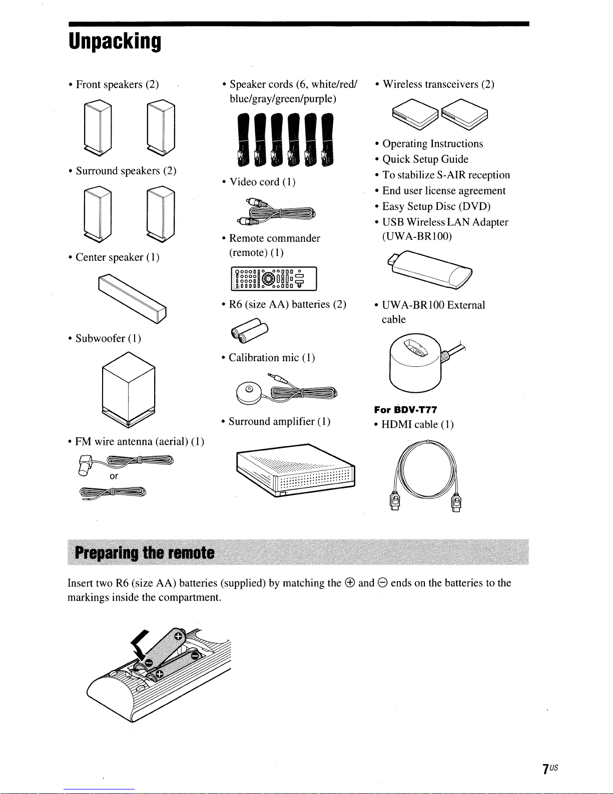
Unpacking
• Front speakers (2)
• Surround speakers (2)
• Center speaker
• Subwoofer (1)
(I)
• Speaker cords (6, white/redl
blue/gray/greenlpurple)
111111
• Video cord (1)
• Remote commander
(remote)
OOODIO
Dgggg
~
~DDDD
• R6 (size AA) batteries (2)
• Calibration mic (1)
(1)
00000
0
0
"080
~ooooCijl
=
• Wireless transceivers (2)
• Operating Instructions
• Quick Setup Guide
• To stabilize S-AIR reception
• End user license agreement
• Easy Setup Disc (DVD)
• USB Wireless LAN Adapter
(UWA-BRlOO)
• UWA-BRIOO External
cable
• Surround amplifier
• FM wire antenna (aerial)
Insert two R6 (size AA) batteries (supplied) by matching the
markings inside the compartment.
(1)
(1)
For
BDV.T77
• HDMI cable (1)
(±)
and 8 ends on the batteries to the
US
7
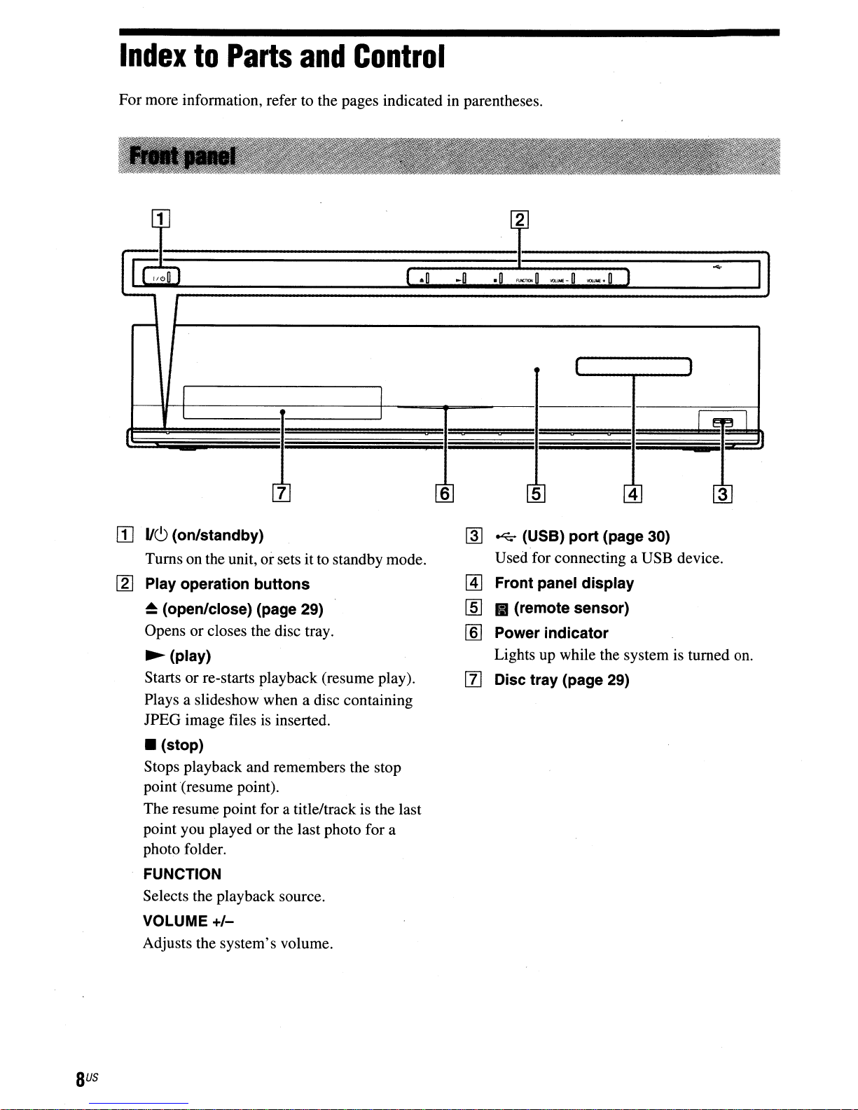
Index
For more information, refer to the pages indicated in parentheses.
.--
1100
to
Parts
and
Control
[
.0
~O
.0
~~O
---.
.......-.
I I
I I
",..-0
I I
---0
J
.....
I
I
~~l
7
[I]
·11(9
(on/standby)
Turns on the unit, orsets it to standby mode.
[2J
Play operation buttons
~
(open/close) (page 29)
Opens or closes the disc tray.
~
(play)
Starts or re-starts playback (resume play).
Plays a slideshow when a disc containing
is
JPEG image files
• (stop)
Stops playback and remembers the stop
point(resume point).
The resume point for a title/track is the last
point you played or the last photo for a
photo folder.
FUNCTION
Selects the playback source.
inserted .
6 5
~
~
(USB) port (page 30)
Used for connecting a USB device.
~
Front panel display
~
• (remote sensor)
[§] Power indicator
Lights up while the system is turned on.
mDisc tray (page 29)
4
VOLUME
Adjusts the system's volume.
BUS
+/-
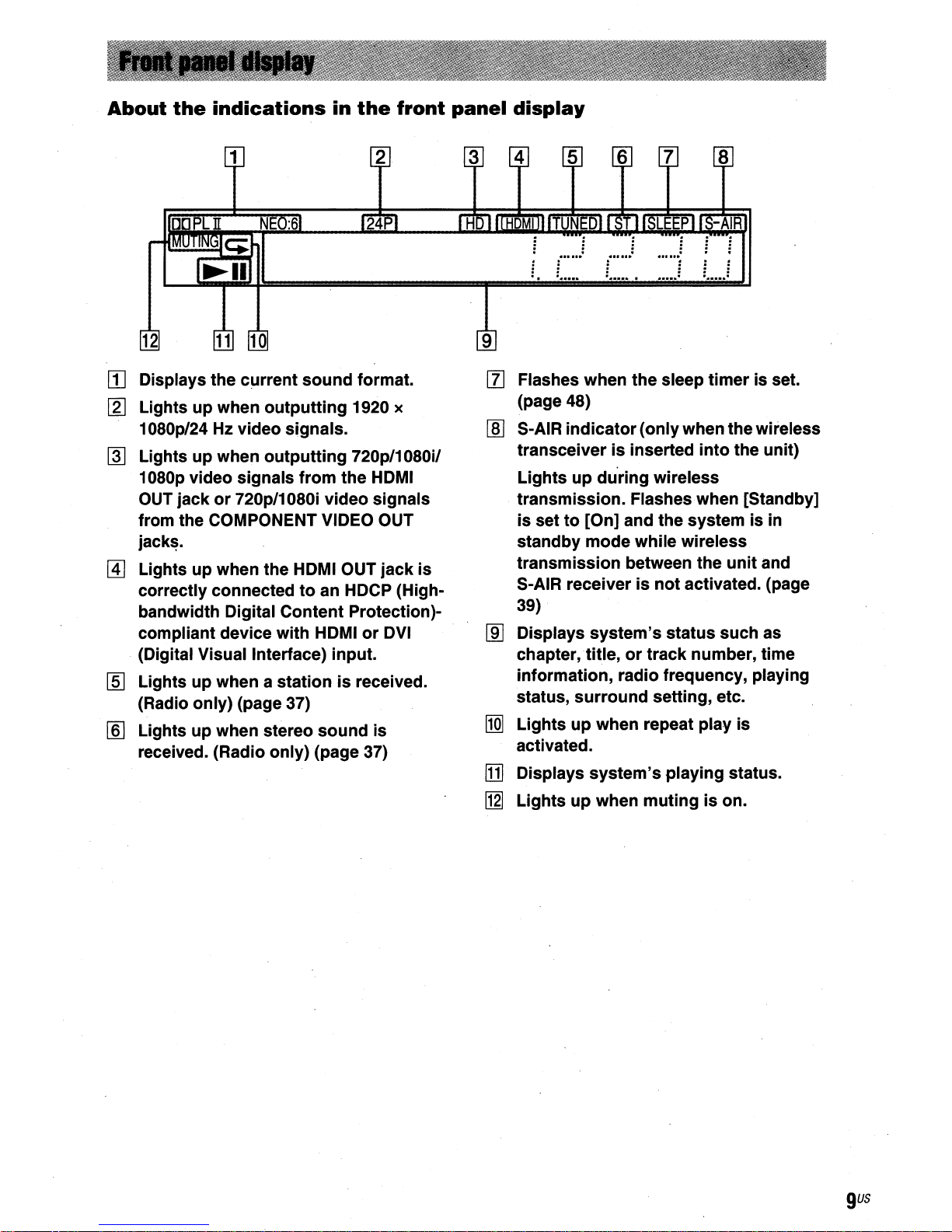
About
the
indications
in
the
front
panel
display
[j]
Displays the current sound format.
[g]
Lights up when outputting 1920 x
Hz
1080p/24
Lights up when outputting 720p/1080i!
rnJ
1080p video signals from the
OUT
jackor720p/1080i video signals transmission. Flashes when [Standby]
from the COMPONENT VIDEO
jack~.
Lights up when the
~
correctly connected
bandwidth Digital Content Protection)compliant device with
(Digital Visual Interface) input.
[ID
Lights up when a stationisreceived.
(Radio only) (page
[ID
Lights up when stereo sound is
received. (Radio only) (page
video signals.
HDMI
toanHDCP
HDMIorDVI
37)
OUT
37)
HDMI
OUT
jack is
(High-
[I]
Flashes when the sleep timer is set.
(page 48)
[§]
S-AIR indicator(onlywhen the wireless
is
transceiver
Lights up during wireless
is
setto[On] and the system is in
standby mode while wireless
transmission between the unit and
S-AIR receiver is
39)
Displays system's status such
rnJ
chapter,title,
information, radio frequency, playing
status, surround setting, etc.
Lights up when repeat play is
l1m
activated.
[j]
Displays system's playing status.
[12J
Lights up when mutingison.
inserted into the unit)
not
activated. (page
or
track number, time
as
gus
13
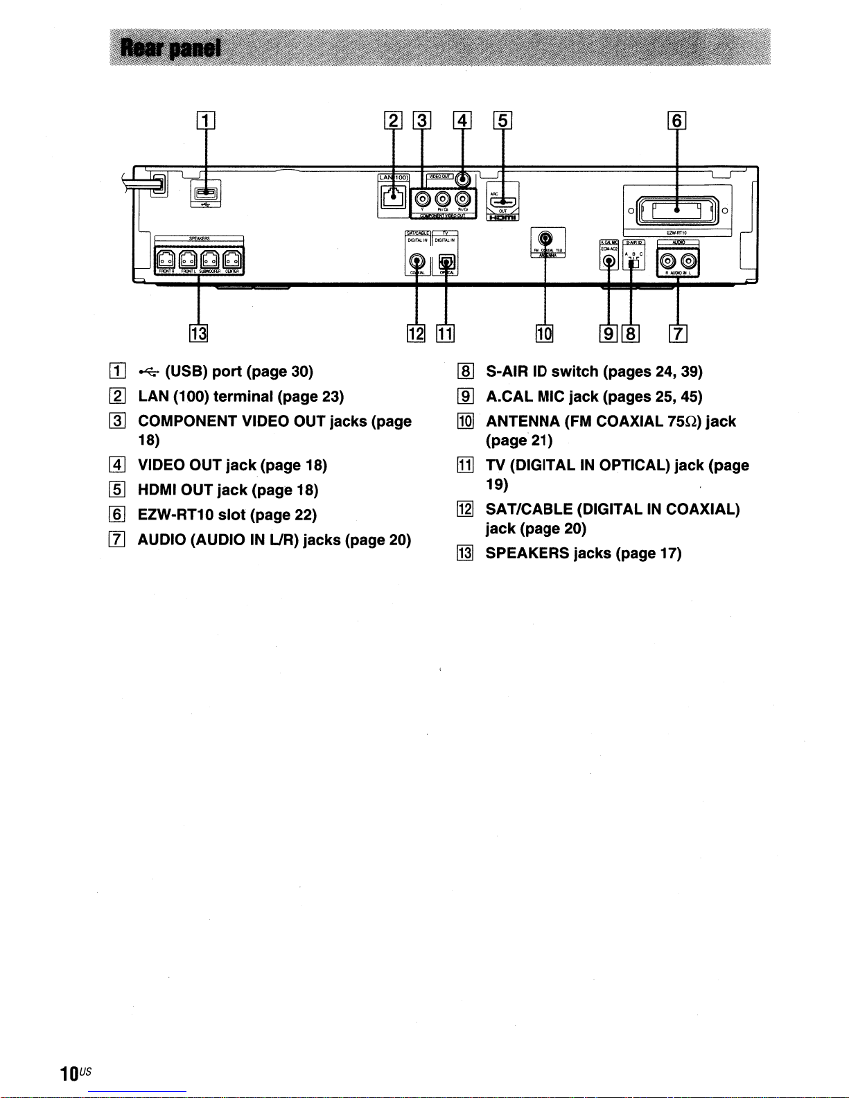
[I]
~
(USB)
[gJ
LAN (100) terminal (page 23)
COMPONENT VIDEO OUT jacks (page
~
18)
port
(page 30)
S-AIRIDswitch
rnJ
A.CAL MIC
lID
ANTENNA (FM COAXIAL
11m
(page 21)
jack
6
(pages 24, 39)
(pages 25, 45)
7511)
jack
[!J
VIDEO OUT
[§J
HDMI OUT
[§]
EZW-RT10
[I]
AUDIO (AUDIOINUR)
jack
jack
slot
(page 18)
(page 18)
(page 22)
jacks
(page 20)
[11J
TV (DIGITALINOPTICAL)
19)
[1g]
SAT/CABLE (DIGITALINCOAXIAL)
jack
(page 20)
SPEAKERS
~
jacks
(page 17)
jack
(page
US
10
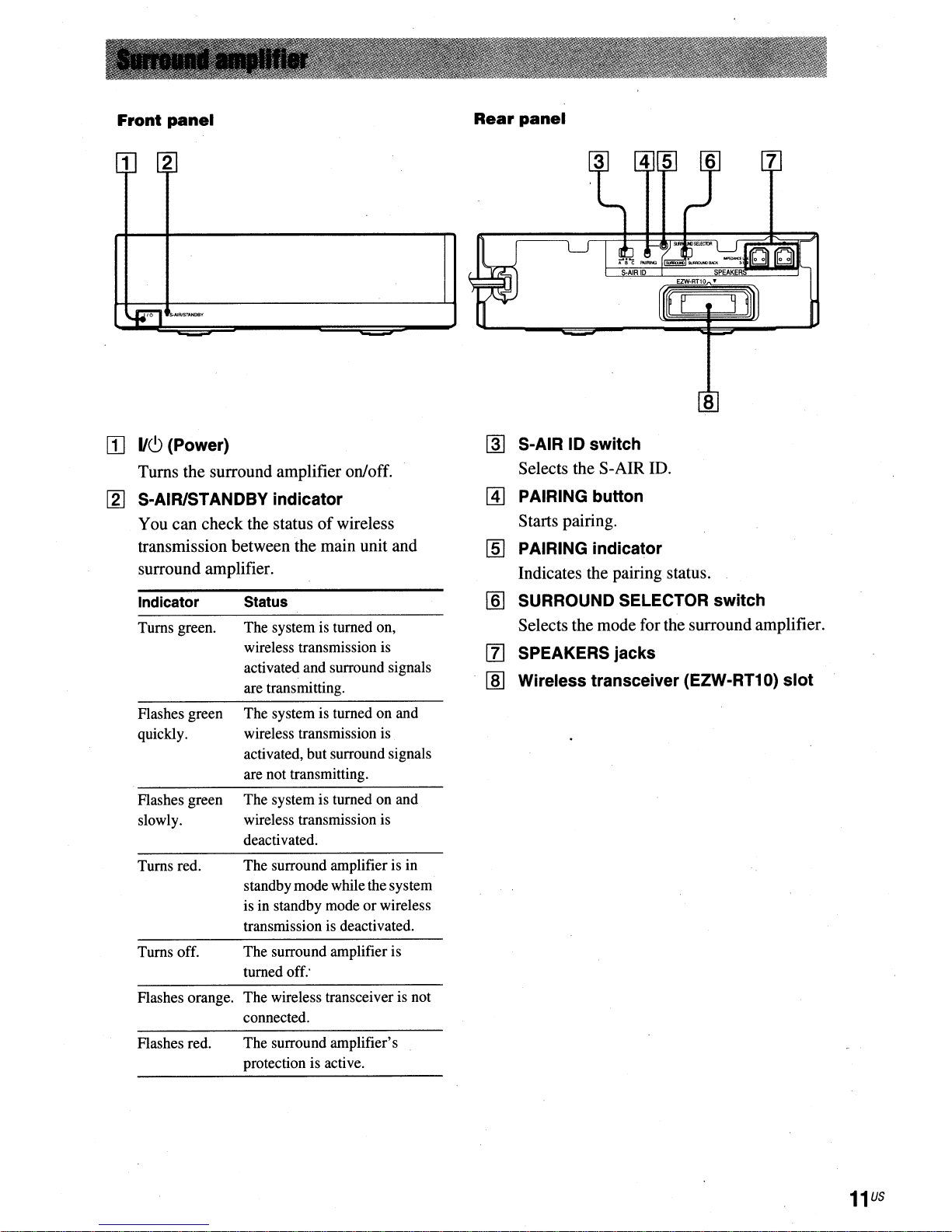
Front
panel
1 2
[]
11(9
(Power)
Turns the surround amplifier on/off.
[2]
S-AIRISTANDBY indicator
You can check the statusofwireless
transmission between the main unit and
surround amplifier.
Rear
panel
~
S·AIR ID switch
Selects the S-AIR ID.
@]
PAIRING button
Starts pairing.
[§]
PAIRING indicator
Indicates the pairing status.
Indicator
Turns green.
Flashes green
quickly.
Flashes green
slowly.
Turns red.
Turns off.
Flashes orange. The wireless transceiver is not
Flashes red.
Status
The system is turned on,
wireless transmission is
activated and surround signals
are transmitting.
The system is turned on and
wireless transmission is
activated, but surround signals
are not transmitting.
The system is turned on and
wireless transmission is
deactivated.
The surround amplifier is in
standby mode while the system
isinstandby modeorwireless
transmission is deactivated.
The surround amplifier is
turned off:
connected.
The surround amplifier's
protection is active.
[§]
SURROUND SELECTOR switch
Selects the mode for the surround amplifier.
!Il SPEAKERS jacks
rID
Wireless transceiver (EZW-RT10) slot
o@@@
SYSTEM
o0®®
FAVORITE
AUDIO
08
II
I
PRESET-REPLAY
1E!!II.·II·.II-1
TUNING-
[B]
@
0 0
L N
II
II
ADVANCE
P.LAY
~o
SUBTITLE
I
PRESET
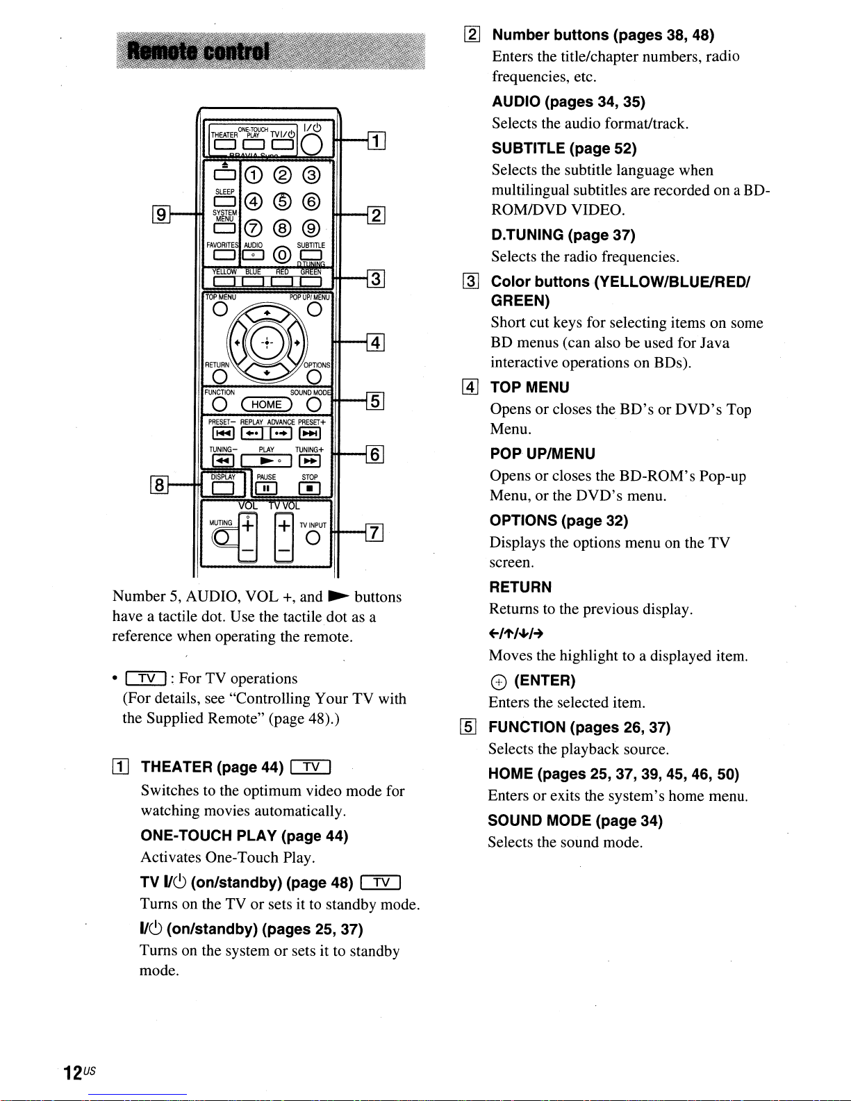
I2J
Number buttons (pages 38, 48)
Enters the title/chapter numbers, radio
frequencies, etc.
AUDIO (pages 34, 35)
Selects the audio format/track.
SUBTITLE (page 52)
Selects the subtitle language when
multilingual subtitles are recorded
on
a BD-
ROM/DVD VIDEO.
D.TUNING (page 37)
Selects the radio frequencies.
~
Color
buttons
(YELLOW/BLUEIRED/
GREEN)
Short cut keys for selecting items on some
BD
menus (can also be used for
Java
interactive operations on BDs).
@]
TOP MENU
+
Menu.
Opensorcloses the
BD'sorDVD's
Top
POPUP/MENU
Opensorcloses the
Menu, or the
DVD's
BD-ROM's
menu.
Pop-up
Number 5, AUDIO,
VOL
+, and
~
buttons
have a tactile dot. Use the tactile dot as a
reference when operating the remote.
•
Cf2]:
(For details, see "Controlling
For TV operations
Your
TV with
the Supplied Remote" (page 48).)
[0
THEATER(page44)Cf2]
Switches to the optimum video mode for
watching movies automatically.
ONE-TOUCH PLAY (page 44)
Activates One-Touch Play.
TV
116
(on/standby) (page 48)
Cf2]
Turns on the TVorsets it to standby mode.
OPTIONS (page 32)
Displays the options menu on the
screen.
RETURN
Returns to the previous display.
+-IJf'/.J,H
Moves the highlight to a displayed item.
CD
(ENTER)
Enters the selected item.
[§]
FUNCTION (pages 26, 37)
Selects the playback source.
HOME (pages 25, 37, 39, 45,
Entersorexits the
system's
home menu.
SOUND MODE (page 34)
Selects the sound mode.
TV
46,50)
116
(on/standby) (pages 25, 37)
Turns on the systemorsets it to standby
mode.
US
12
[§]
Playback operation
See "Playback" (page 29).
.....
/~
(previous/next)
Skip to the previous/next chapter, track,
file.
.-/
...
(replay/advance)
Briefly replay the current scenes for 10
seconds./Briefly fast forwards the current
scenes for15seconds.
~/~
Fast reverse/fast forward the disc during
playback. Each time you press the button,
search speed changes.
Activates slow-motion play when pressed
for more than one second in pause mode.
Plays one frame at a time when pressed in
pause mode.
~
Starts or re-starts playback (resume play).
Plays a slideshow when a disc containing
JPEG image files is inserted.
(fast reverse/fast forward)
(play)
buttons
or
lID
DISPLAY (pages 29, 31)
Displays the playback information
TV screen.
When the function is
CABLE" and digital signals are input via
the DIGITAL IN jack, displays the stream
information in the front panel display.
[ID
~
(open/close)
Opens or closes the disc tray.
SLEEP (page 48)
Sets the sleep timer.
SYSTEM MENU (pages 27, 32, 35, 37)
Enters the system menu.
FAVORITES
Displays the Internet contents added to the
Favorites List. You can save
Internet contents.
"TV"
or "SAT/
18
onthe
favorite
II
(pause)
Pauses or re-starts playback.
• (stop)
Stops playback and remembers the stop
point (resume point). The resume point for
a title/track is the last point you played or
the last photo for a photo folder. .
Radio operation
See "Tuner" (page 37).
PRESET
TUNING
[I]
MUTING
Turns offthe sound temporarily.
VOL
Adjusts the volume.
TV
Adjusts the TV volume.
TV
Switches the
TV and other input sources.
+/-
VOL
INPUT
+/-
+/-
(page 37)
+/-
em
buttons
em
TV's
input source between
the·
13
US
Getting
Started
Step
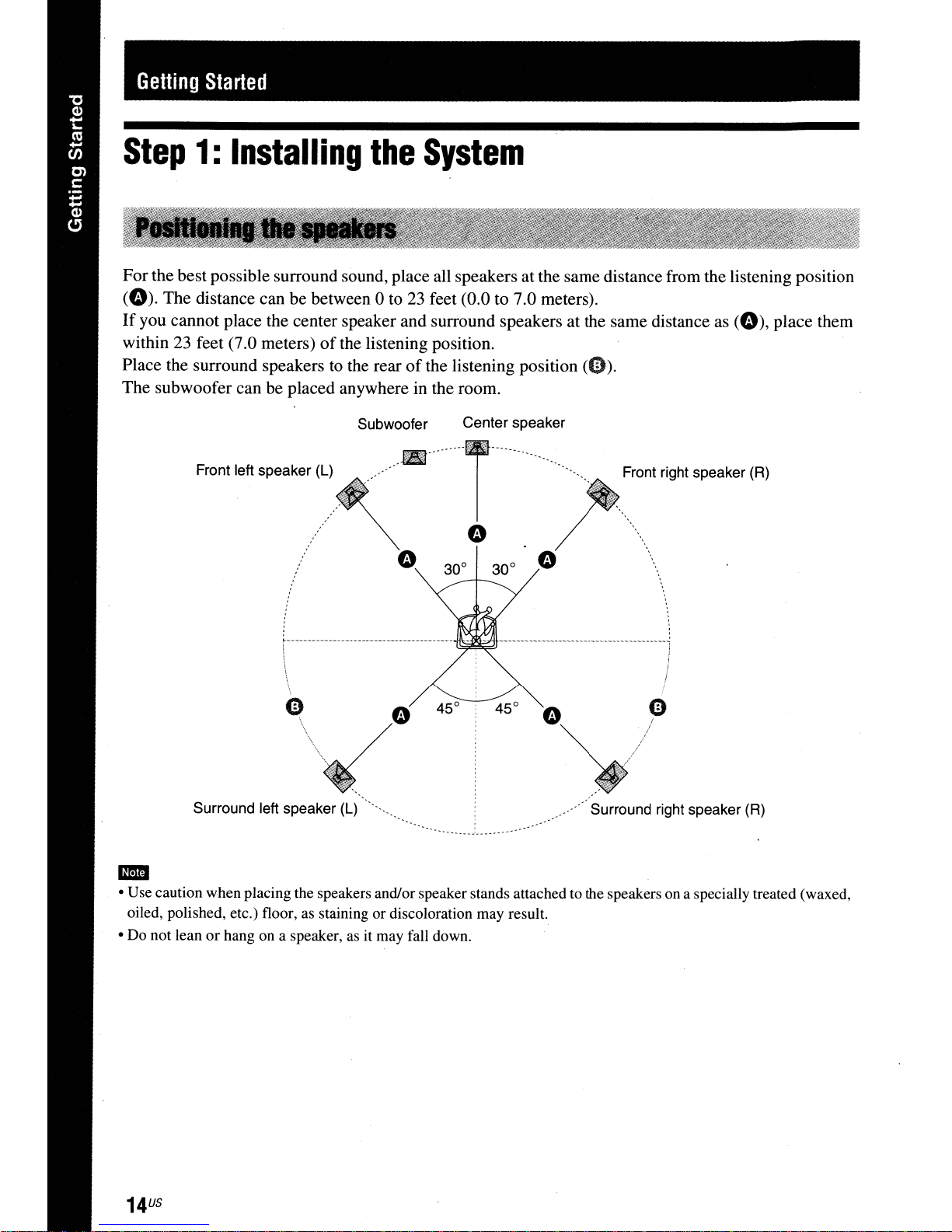
For the best possible surround sound, place all speakers at the same distance from the listening position
(0).
If
you cannot place the center speaker and surround speakers at the same distance
within 23 feet (7.0 meters)
Place the surround speakers to the rear
The subwoofer can be placed anywhereinthe room.
1:
Installing
The distance can be between 0 to23feet (0.0 to 7.0 meters).
of
Front left speaker (L)
the
the listening position.
Subwoofer
.............. . .
System
of
the listening position
Center speaker
······T"';.......
(0).
as
(0),
Front right speaker (R)
place them
o
1-------..--
!
-------------
-------
-.----
----
\
Surround left speaker
(L)
Surround right speaker (R)
..
• Use caution when placing the speakers and/or speaker stands attached to the speakersona specially treated (waxed,
oiled, polished, etc.) floor, as staining or discoloration may result.
• Do not lean
or
hang on a speaker, as it may fall down.
US
14
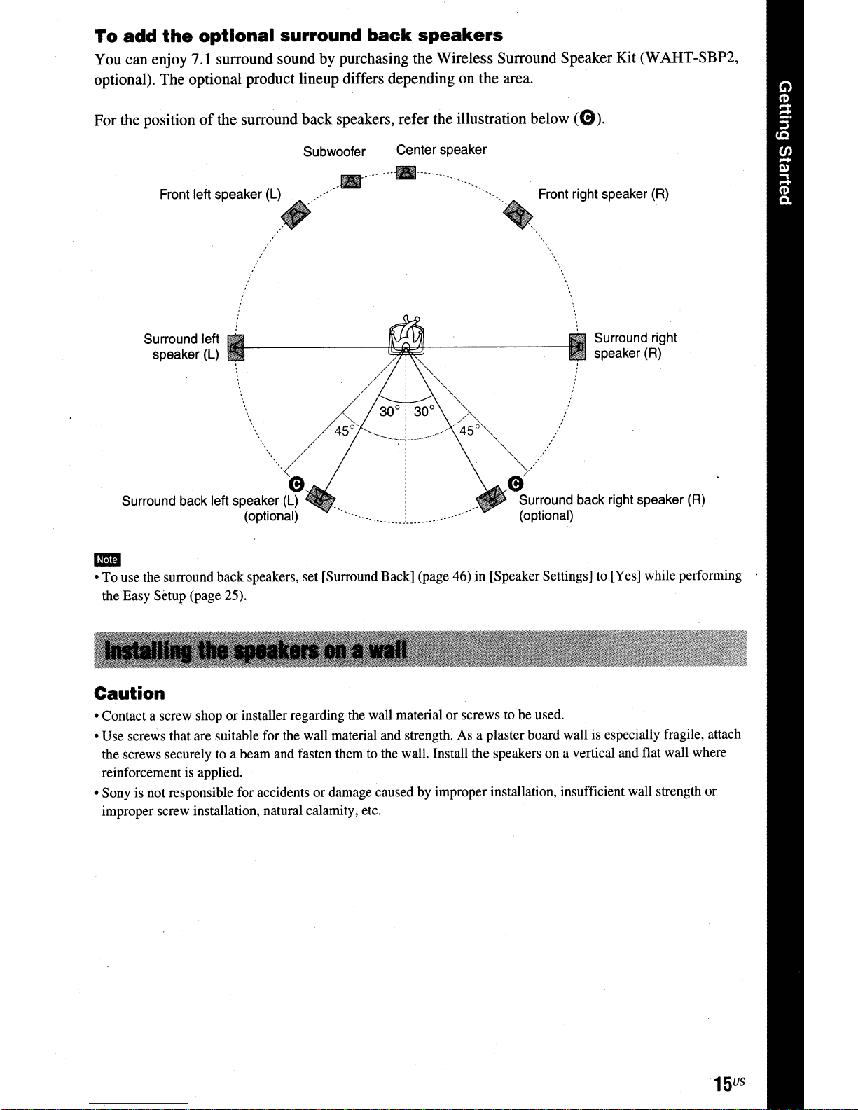
To
add
the
optional surround
You can enjoy 7.1 surround sound by purchasing the Wireless Surround Speaker Kit (WAHT-SBP2,
optional). The optional product lineup differs depending on the area.
back
speakers
For the positionofthe surround back speakers, refer the illustration below
Center speaker
_-.----_._-
""'''''
' :
" : _../
-------~---_.
" "
,________
.
""",
'A
<~5
~"
".
Front right speaker
"
'"
'" .
ci'
Surround back right speaker
(optional)
Front left speaker
Surround left
speaker
Surround back left speaker
(L)
(L)
(optional)
Subwoofer
..•.......
. 30° : 30°
4SJ--
A
/ :
"-<
'$
(L)
(0).
(R)
Surround right
speaker(R)
(R)
1m
• To use the surround back speakers, set [Surround Back] (page 46)in[Speaker Settings] to [Yes] while performing
the Easy Setup (page 25).
Caution
• Contact a screw shoporinstaller regarding the wall materialorscrews to be used.
• Use screws that are suitable for the wall material and strength. As a plaster board wall is especially fragile, attach
the screws securely to a beam and fasten them to the wall. Install the speakers
reinforcement is applied.
• Sony is not responsible for accidents or damage caused by improper installation, insufficient wall strength or
improper screw installation, natural calamity, etc.
ona
vertical and flat wall where
15
US
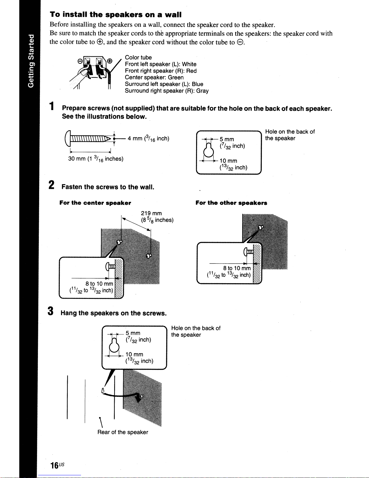
To
install
Before installing the speakers on a wall, connect the speaker cord to the speaker.
Be sure to match the speaker cords to
the color tube to
the
speakers
®,
and the speaker cord without the color tube to
Color tube
Front left speaker (L): White
Front right speaker (R): Red
Centerspeaker: Green
Surround left speaker (L): Blue
Surround right speaker (R): Gray
onawall
th~
appropriate terminals on the speakers: the speaker cord with
e.
1 Prepare screws (not supplied) that are suitable for the hole on the back of each speaker.
See the illustrations below.
G\\\\\\\\\\\\\\1>
~ ~
30
mm
(1
3/
16
t--
inches)
4 mm (3/16inch)
2 Fasten the screws to the wall.
For
the
center
speaker
219mm
(8%
inches)
For
the
other
speakers
Hole on the back
the speaker
of
3 Hang the speakers on the screws.
Rear of the speaker
US
16
Holeonthe back of
the speaker
Step
For connecting the system, read the information on the following pages.
Do not connect the AC power cord (mains lead)
connections are made.
• When you connect another component with a volurpe control, tum down the volumeofthe other components to a
-
level where sound is not distorted.
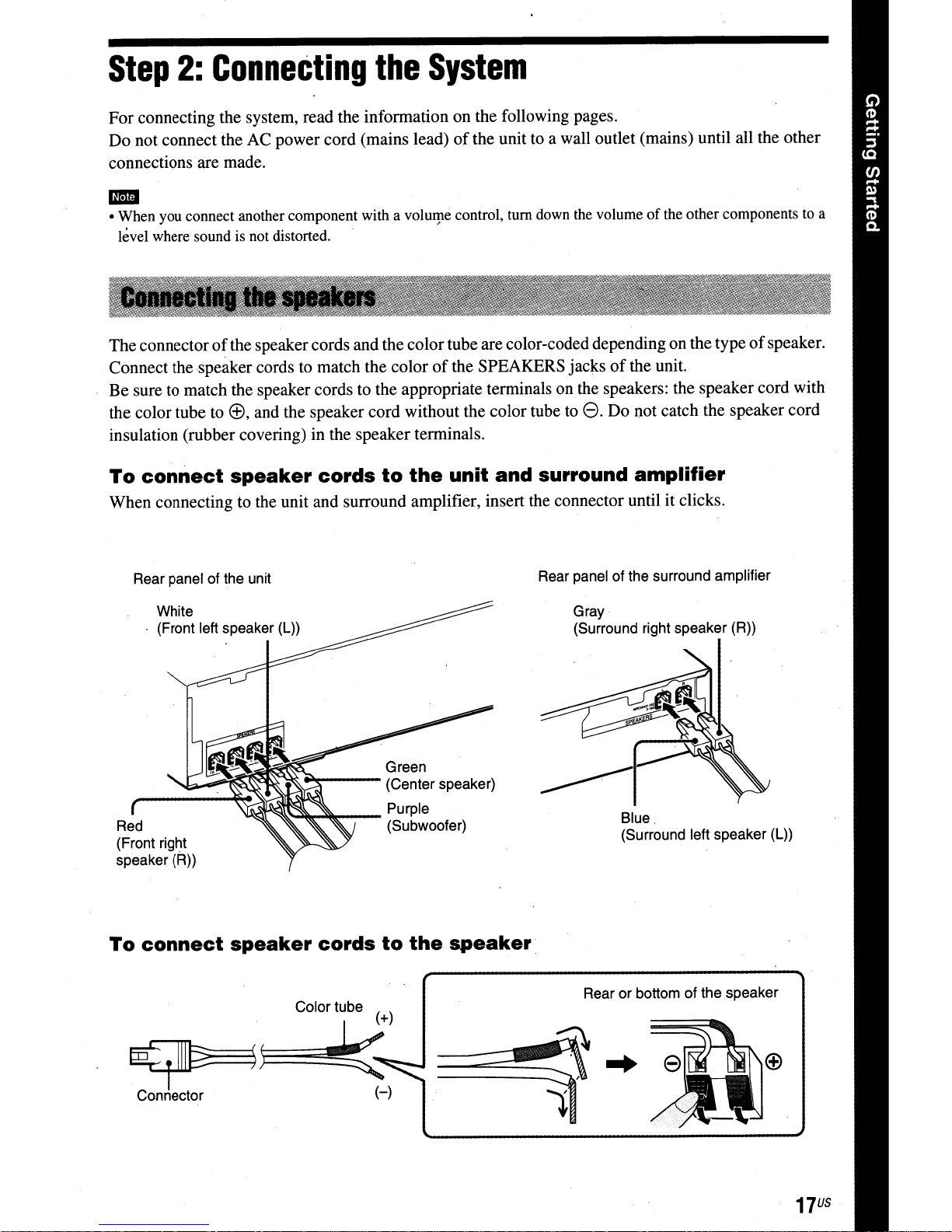
The connectorofthe speakercords and the color tube are color-coded depending on the typeofspeaker.
Connect the speaker cords to match the color
Be sure to match the speaker cords to the appropriate terminals on the speakers: the speaker cord with
the color tube to
insulation (rubber covering) in the speaker terminals.
To
When connecting to the unit and surround amplifier, insert the connector until it clicks.
2:
connect
Connecting
ffi, and the speaker cord without the color tube to
speaker
cords
the
to
the
System
of
the unit to a wall outlet (mains) until all the other
of
the SPEAKERS jacksofthe unit.
unit
and
8.
Do not catch the speaker cord
surround
amplifier
Rear panel of the unit
White
{Front left speaker (L))
Green
~---
~----\$~~~~
Red (Subwoofer)
{Front right
speaker (R))
To
connect
speaker
__
cords
(Center speaker)
Purple
to
the
Rear panel of the surround amplifier
Gray·
{Surround right speaker (R))
Blue.
{Surround left speaker (L))
speaker.
Rear or bottom of the speaker
~j;:::=~
Connector·
17
US

This connection sends a video signal to the TV.
Depending on the jacks on your TV, select the connection method.
Rear panel of the unit
oComponent video
cable (not supplied)
e Video cord (supplied)
To the component
video input jacks of
the TV.
* The HDMI cable
Method
If
your
TV
has an HDMIjack, connect to the TV with an HDMIcable. Picture quality will be improved
compared to using the component video cable connection
When connecting with the HDMI cable, you need to select the type
Method
If
your TV does not haveanHDMIjack, but has component video inputjacks, connect to the
a component video cable. Picture quality will be improved compared to using the video cord
connection.
When connecting
51).
2:
is
supplied with
1:
HDMI
Component
with
BDV-Tn
cable
(0)
video
the component video cable, you need to select the typeofoutput signal (page
only.
connection
cable
---~
To
the video input
jack of the TV.
(0)
connection
To the HDMIIN jack
of the TV.
or
the video cord connection.
of
output signal (page 51).
TV
with
Method
If
you do not have an HDMI cableora component video cable, temporarily make this connection.
US
18
3:
Video
cord
(e)
connection
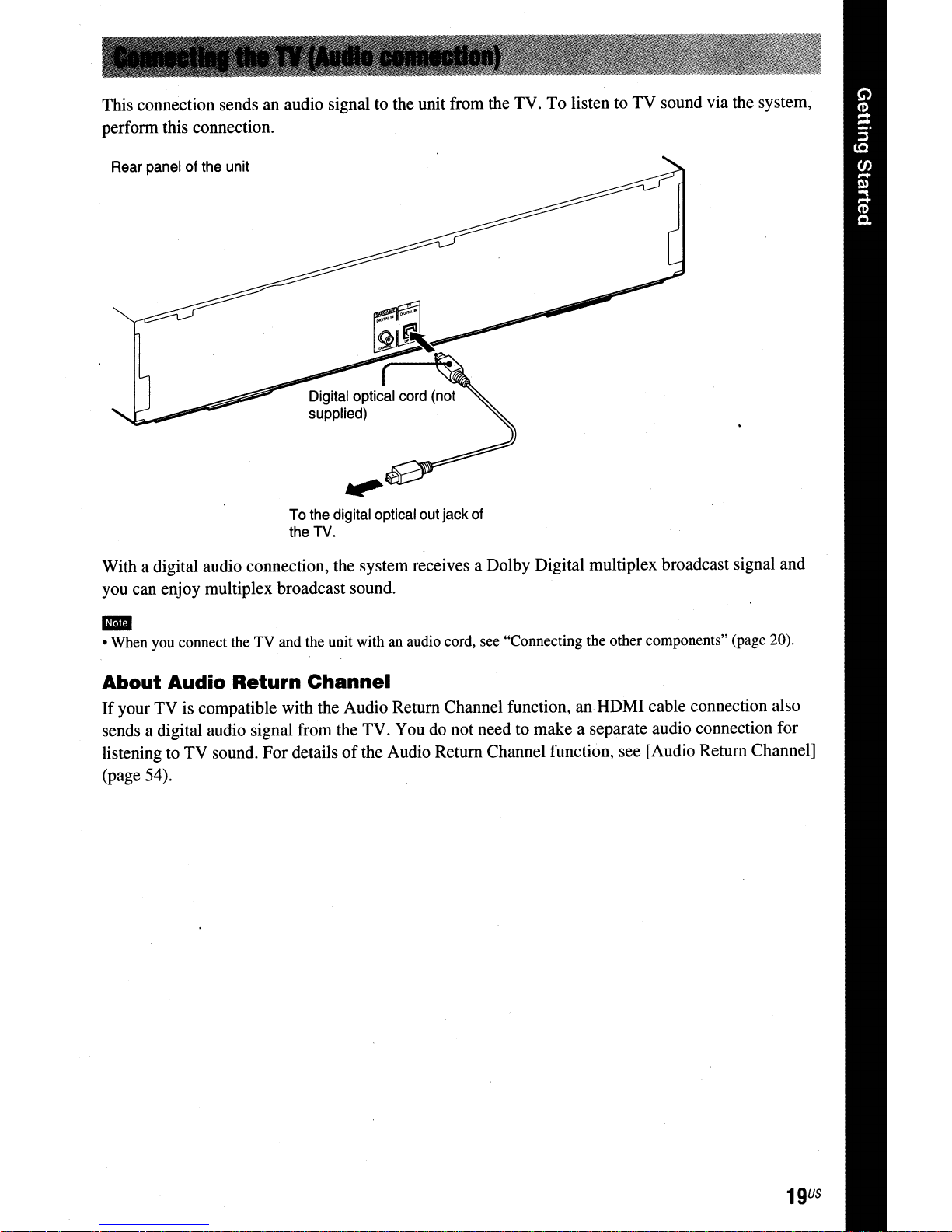
This connection sends an audio signal to the unit from the TV.Tolisten to
perform this connection.
Rear
panelofthe
unit
To
the
the
TV.
digital optical
out
jack of
TV
sound via the system,
With a digital audio connection, the system receives a Dolby Digital multiplex broadcast signal and
you can enjoy multiplex broadcast sound.
• When you connect the TV and the unit with an audio cord, see "Connecting the other components" (page 20).
-
About Audio Return Channel
If
your TV is compatible with the Audio Return Channel function, an HDMI cable connection also
sends a digital audio signal from the TV. You do not need to make a separate audio connection for
listening to TV sound. For details
(page 54).
of
the Audio Return Channel function, see [Audio Return Channel]
19
U5
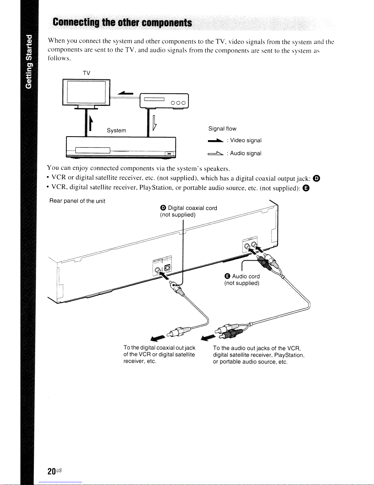
When
components
follows.
you connect the system and other components to the TV, video signals from the system and the
are sent to the TV. and audio signals from the components are sent to the system as
TV
~
D
I .
~
System
I-----l
You can enjoy connected components via the
VCR
or
•
•
VCR,
Rear panel of the unit
digital satellite receiver, etc. (not supplied), which has a digital coaxial output jack: e
digital satellite receiver, PlayStation,
II
I
~
r
...
4:)
Digital coaxial cord
(not supplied)
0001
Signal flow
........... :Video signal
l
system's
or
portable audio source, etc. (not supplied): G
=!::::=:..
speakers.
: Audio signal
To the digital coaxial out jack
of
receiver, etc.
US
20
the VCR or digital satellite
To the audio out jacks of the VCR,
digital satellite receiver, PlayStation,
or portable audio source, etc.
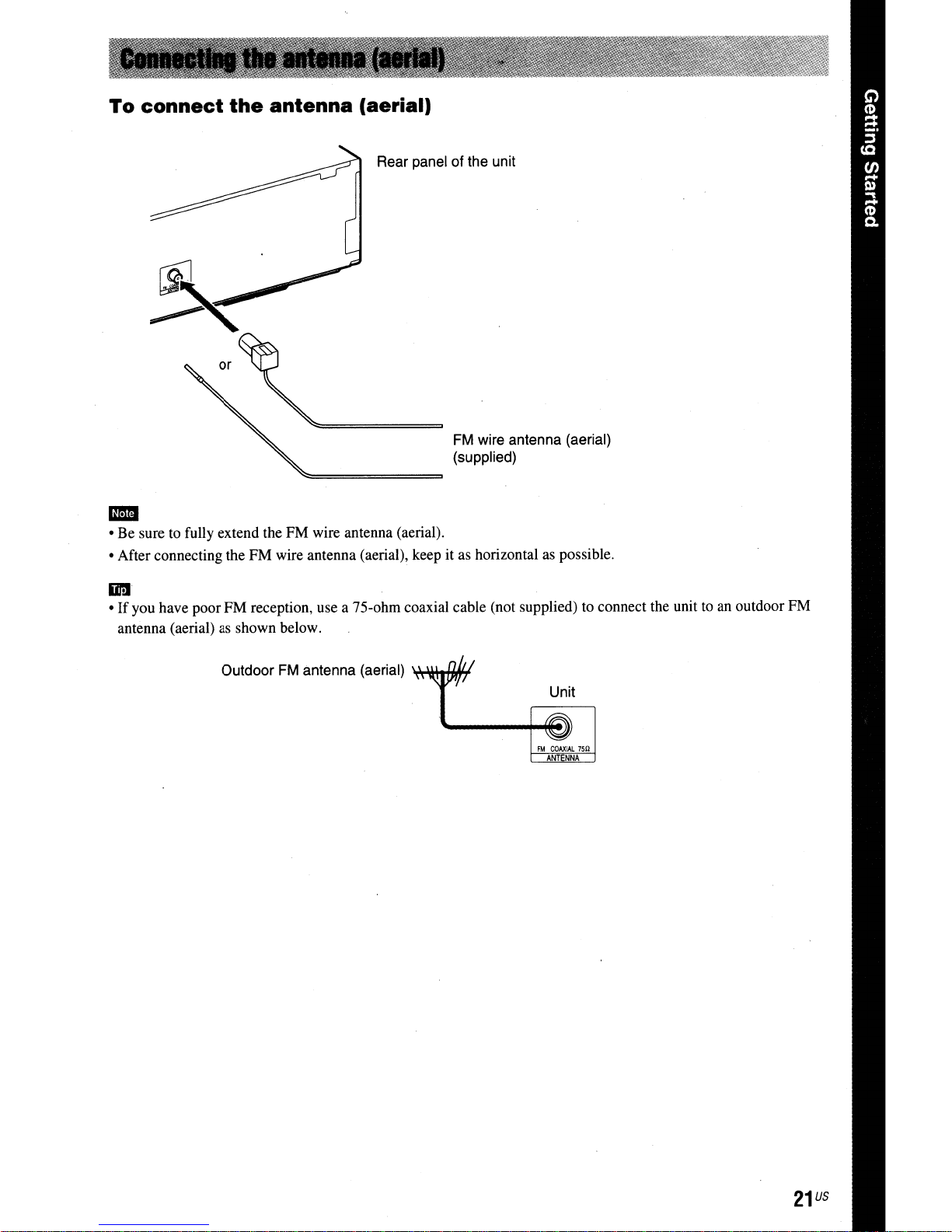
To
connect
the
antenna
(aerial)
Rear panel of the unit
FM wire antenna (aerial)
(supplied)
1111
• Be sure to fully extend the FM wire antenna (aerial).
• After connecting the FM wire antenna (aerial), keep it as horizontal as possible.
IIr:I
•Ifyou have poor FM reception, use a 75-ohm coaxial cable (not supplied) to connect the unit to an outdoor FM
antenna (aerial) as shown below.
Outdoor FM antenna (aerial)
'*.lIl+I+fIH
Unit
21
us
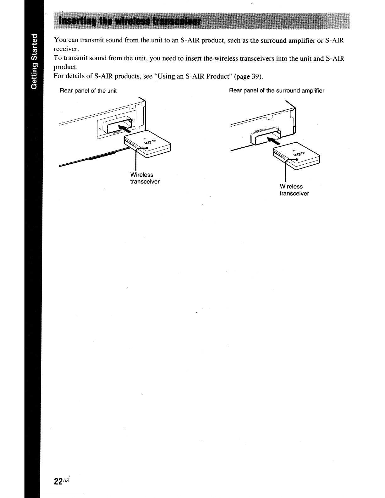
You can transmit sound from the unit to an S-AIR product, suchasthe surround amplifierorS-AIR
receiver.
To
transmit sound from the unit, you need to insert the wireless transceivers into the unit and S-AIR
product.
of
For details
S-AIR products, see "Using an S-AIR Product" (page 39).
Rear panel of the unit
Wireless
transceiver
Rear panel of the surround amplifier
Wireless
transceiver
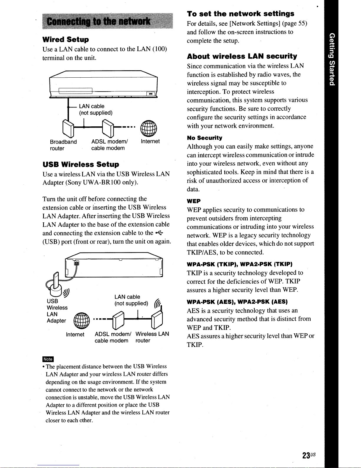
Wired
Use a LAN cable to connect to the LAN
terminal on the unit.
Setup
(l00)
...
LAN
cable
(not supplied)
Broadband
router
USB
Use a wireless LAN via the USB Wireless LAN
Adapter (Sony
Tum
extension cable or inserting the USB Wireless
LAN Adapter. After inserting the USB Wireless
LAN Adapter to the base
and connecting the extension cable to the
(USB) port (front or rear),
Wireless
the unit
ADSL modem/
cable modem
Setup
UW
A-BR100 only).
off
before connecting the
of
the extension cable
tum
Internet
~
the unit on again.
To
set
the
network
For details, see [Network Settings] (page 55)
and follow the on-screen instructions to
complete the setup.
About
Since communication via the wireless LAN
function is established by radio waves, the
wireless signal may be susceptible to
interception.
communication, this system supports various
security functions.
configure the security settings
with your network environment.
No
Although you can easily make settings, anyone
can intercept wireless communication or intrude
into your wireless network, even without any
sophisticated tools. Keep in mind that there
risk
data:.
WEP
WEP applies security to communications
prevent outsiders from intercepting
communications or intruding into your wireless
network. WEP is a legacy security technology
that enables older devices, which do not support
wireless
To
protect wireless
Be
Security
of
unauthorized access or interception
settings
LAN
sure to correctly
security
in
accordance
is
of
to
TKIP/AES, to be connected.
a
USB
Wireless
LAN
Adapter
• The placement distance between the USB Wireless
-
LAN Adapter and your wireless LAN router differs
depending on the usage environment.Ifthe system
cannot connect to the networkorthe network
connection is unstable, move the USB Wireless LAN
Adapter to a different position or place the USB
Wireless LAN Adapter and the wireless LAN router
closer to each other.
~
~
Internet ADSL modem/ Wireless
cable modem router
LAN
WPA·PSK
TKIP is a security technology developed to
correct for the deficiencies
assures a higher security level than WEP.
WPA·PSK (AES),
AES is a security technology that uses an
advanced security method that is distinct from
WEP and TKIP.
AES assures a higher security level than WEPor
TKIP.
(TKIP),
WPA2·PSK
of
WPA2·PSK
(TKIP)
WEP. TKIP
(AES)
23
US
Step
3:
S-AIR
Setting
Wireless
up
the
System
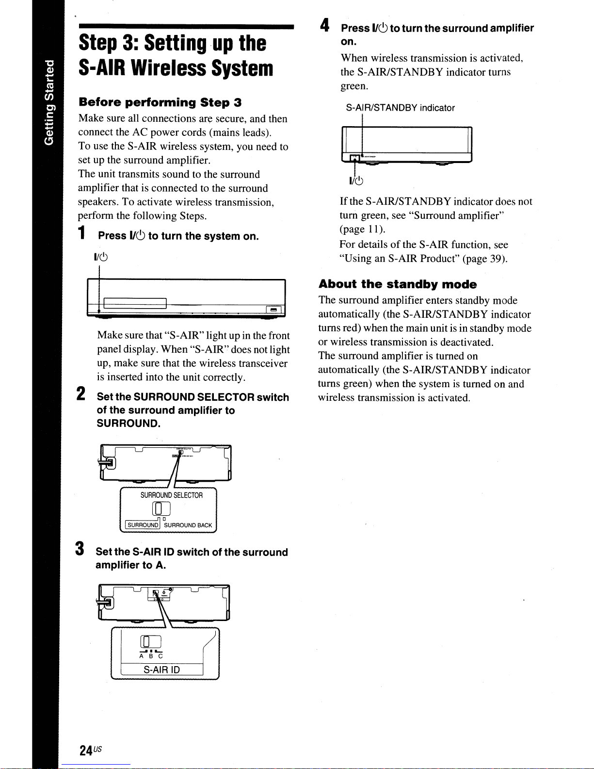
4 Press
on.
When wireless transmission is activated,
the S-AIRISTANDBY indicator turns
green.
1/6
toturn the surround amplifier
Before
Make sure all connections are secure, and then
connect the AC power cords (mains leads).
To use the S-AIR wireless system, you need to
set up the surround amplifier.
The unit transmits sound to the surround
amplifier that is connected to the surround
speakers. To activate wireless transmission,
perform the following Steps.
performing
Step
3
1 Press 1/6 to turn the system on.
1/(9
~,-.-,
Make sure that "S-AIR" light up in the front
panel display. When "S-AIR" does not light
up, make sure that the wireless transceiver
is inserted into the unit correctly.
2 Set the SURROUND SELECTOR switch
of the surround amplifier to
SURROUND.
S-AIRISTANDBY indicator
II
1"'!1
-
I
11(9
If
the S-AIRIST AND BY indicator does not
tum green, see "Surround amplifier"
(page 11).
For details
"Using an S-AIR Product" (page 39).
About
The surround amplifier enters standby mode
automatically (the S-AIRISTANDBY indicator
turns red) when the main unit is in standby mode
or wireless transmission is deactivated.
The surround amplifier is turned on
automatically (the S-AIRISTANDBY indicator
turns green) when the system
wireless transmission is activated.
the
of
the S-AIR function, see
standby
I
mode
is
turned on and
SURROUND
SELECTOR
[[]
'--1
S-UR-RQ-U-'N01
3 Setthe S-AIR
amplifier to A.
US
24
.......
ABC
S-AIR
°SURROUNO
10
L-
BACK
switchofthe surround
10
Step
Easy
Follow the Steps below to make the basic
adjustments for using the system.
Displayed items vary depending on the country
model.
•Touse the optional surround back speakers, set
-
[Surround Back] in [Speaker Settings] to [Yes]
(page 46).
4:
Performing
Setup
,"--_.'--'."---..
Lt:?
C1
t:;:l~ii.
H---
o0®@
o@J®®
o0®®
OO@C1
crr:::r.c::r.CJ
o
the
1/6
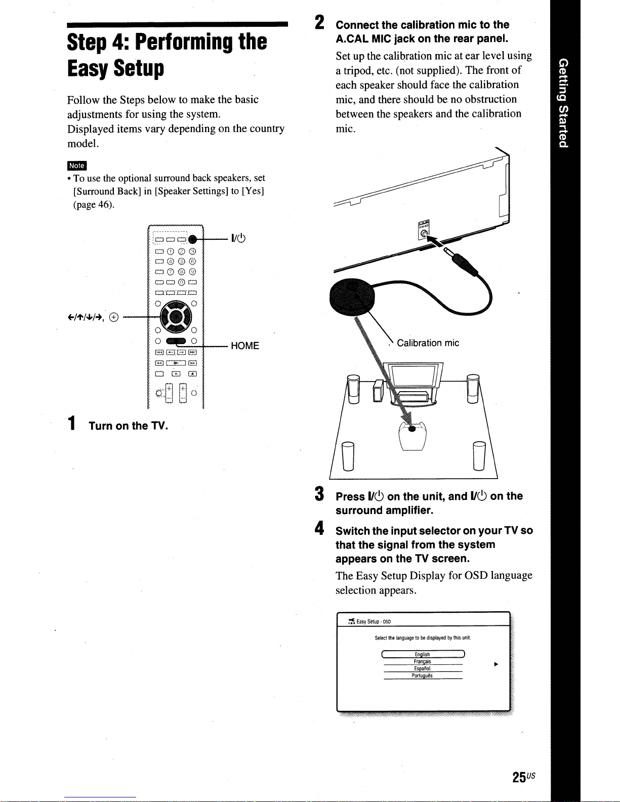
2 Connect the calibration
A.CAL
Set up the calibration mic at ear level using
a tripod, etc. (not supplied). The front
each speaker should face the calibration
mic, and there should be no obstruction
between the speakers and the calibration
mic.
MIC
jack on the rear panel.
mictothe
of
1 Turn on the TV.
--';;;;"-';;'4--HOME
3 Press
surround amplifier.
4 Switch the inputselectoron
that the signal from the system
appears on the
The Easy Setup Display for OSD language
selection appears.
IIC)
on the unit, and
TV
screen.
~
Easy
Setup·
050
Select
the
languagetobe
displayedbythis
English
Francais
Espafiot
PortuQues
IIC)onthe
yourTVso
unit.
25
US
5 Perform the [Easy Setup]. Follow the
on-screen instructions to make the
basic settings usillg
+-I'to/.J,I-+,
and G).
Step
5:
Selecting
the
For details about [Auto Calibration]
in
settings
the Appropriate Settings Automatically"
(page 45).
To
recall
[Easy Setup], see "Calibrating
the
Easy
Setup
1 Press HOME.
The home menu appears on the TV screen.
2 Press
3 Press
press
4 Press
G).
The Easy Setup Display appears.
+-1-+
to
select;;;
'to/oJ,
to select [Easy Setup], then
[Setup].
G).
+-1-+
to select [Start], then press
Display
Source
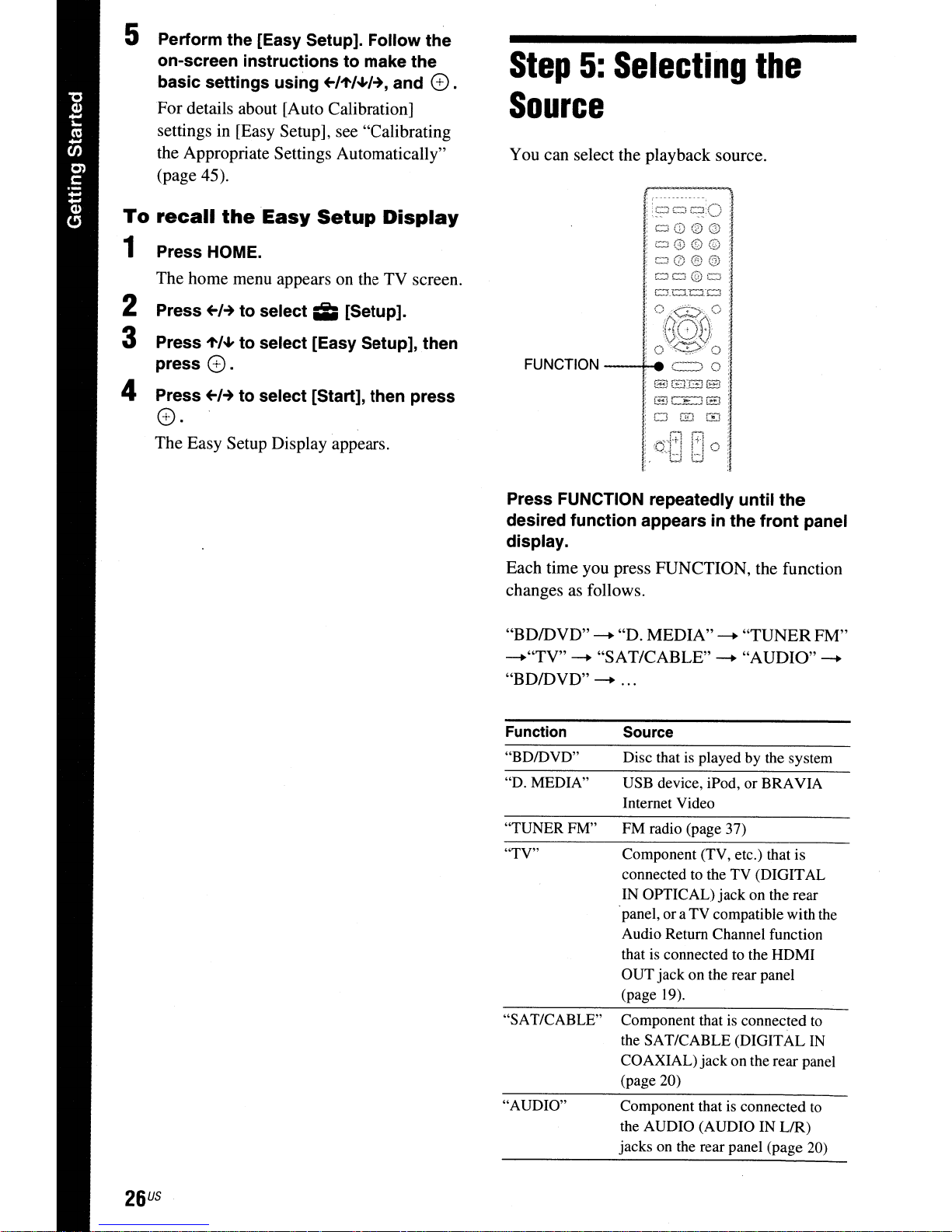
You can select the playback source.
=~:O:
:
,
:,'
o0®@i
;o0©Q:
l;o0®®
oCJ@=:
, ,
'=_==-0:
: 0<::::::7, 0 :
:
r/1(7,;Ci
;
o~'ti!:/io
FUNCTION
Press FUNCTION repeatedly until the
desired function appears
display.
Each time you press FUNCTION, the function
changes
as
follows.
-.-+.
z=::>
88:88
:
:
:
0
in
the front panel
~
"BD/DVD"
~"TV"
"BD/DVD"~...
Function
"BDIDVD"
"D. MEDIA"
"TUNERFM"
"TV"
"SAT/CABLE"
"AUDIO"
~
"D. MEDIA"~"TUNERFM"
"SAT/CABLE"
~
"AUDIO"
Source
Disc thatisplayed by the system
USB device, iPod, or BRAVIA
Internet Video
FM radio (page 37)
Component (TV, etc.) that is
connected to the TV (DIGITAL
IN OPTICAL) jack on the rear
panel, or a TV compatible with the
Audio Return Channel function
that
is
connected to the HDMI
OUTjack on the rear panel
(page 19).
Component that
the SAT/CABLE (DIGITAL
COAXIAL) jack on the rear panel
(page 20)
Component that is connected
the AUDIO (AUDIO IN LIR)
jacks on the rear panel (page 20)
is
connected
to
IN
to
~
US
26
Step
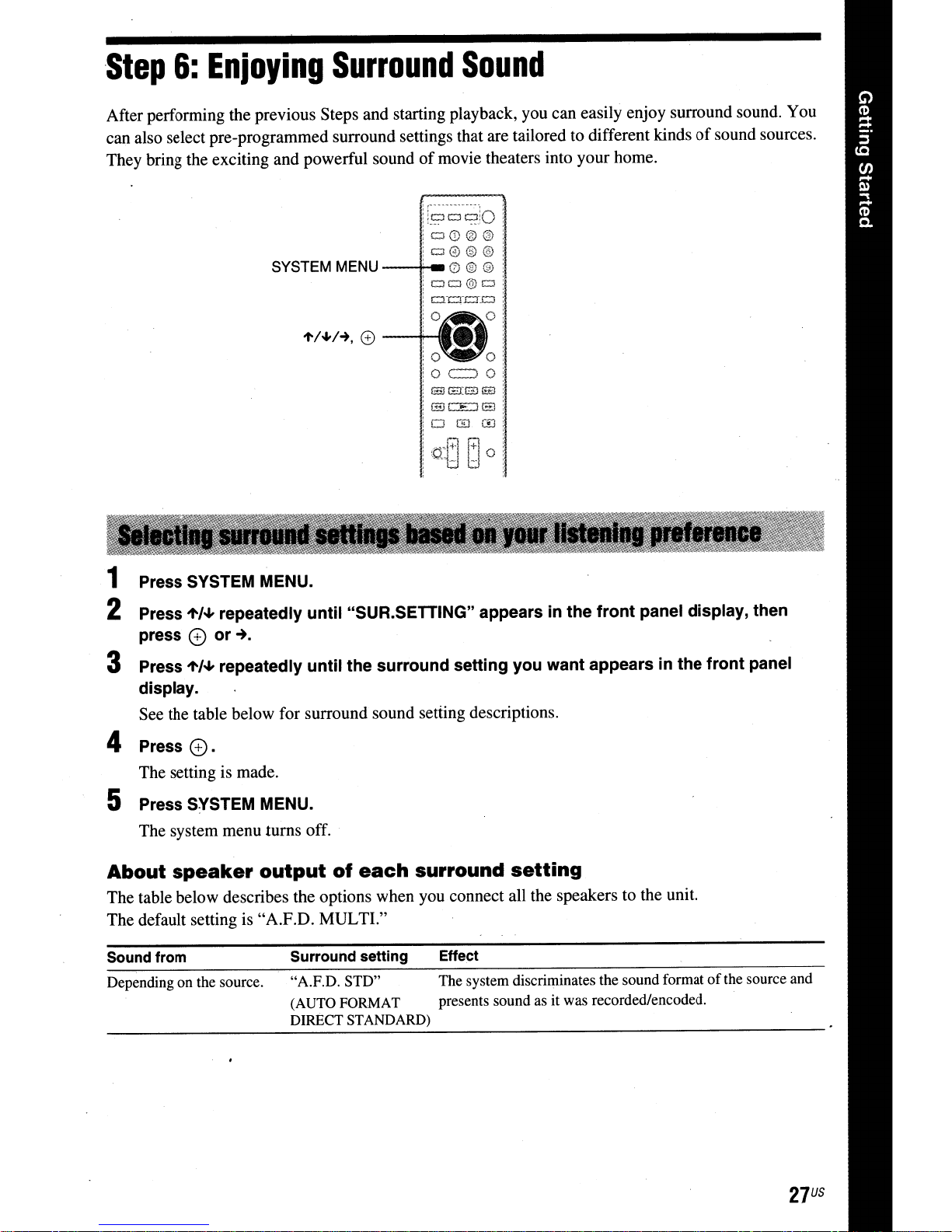
After performing the previous Steps and starting playback, you can easily enjoy surround sound. You
can also select pre-programmed surround settings that are tailored to different kinds
They bring the exciting and powerful sound
6:
Enjoying
Surround
SYSTEM MENU
of
movie theaters into your home.
'i~-~-~]o
CJ0®@
Cl@®@
---t-,
- 0 ® ®
!ClCJ@Cl,
!
Gcn::r.Cl
Sound
:
of
sound sources.
1'/"'/-+,
CD
--+--
SErGS
fEJCE.JEl
OGJm
i,erARoi
;
._i:J
l:J
1 Press SYSTEM MENU.
2 Press
press
3 Press
display.
See the table below for surround sound setting descriptions.
't'/oJ,
repeatedly until "SUR.SETTING" appearsinthe front panel display, then
e
or~.
't'/oJ,
repeatedly until the surround setting you want appears in the front panel
4 Press G).
The setting is made.
:
5 Press SYSTEM MENU.
The system menu turns off.
About
The table below describes the options when you connect all the speakers to the unit.
The default setting is "A.F.D. MULTI."
Sound
Depending on the source.
speaker
from
output
Surround setting Effect
"A.F.D. STD" The system discriminates the sound formatofthe source and
(AUTO FORMAT presents sound as it was recorded/encoded.
DIRECT STANDARD)
of
each
surround
setting
27
US

Sound from
Surround setting
"A.F.D. MULTI"
(AUTO
DIRECT
"PRO LOGIC"
"PLU MOVIE"
"NE06
"NE06MUS"
"2CH STEREO"
FORMAT
MULTI)
CIN"
Effect
• 2 channel source: The system simulates surround sound
from 2 channel sources and outputs sound from the
channel speakers by duplicating 2 channel source sound
across each speaker.
• Multi-channel source: The system outputs sound from the
speakers depending on the number
source.
• 2 channel source: The system simulates surround sound
from 2 channel sources and outputs sound from the
channel s.peakers.
- "PRO LOGIC" performs Dolby Pro Logic decoding.
- "PLU MOVIE" performs Dolby Pro Logic U movie
mode decoding.
• Multi-channel source: The system outputs sound from the
speakers depending on the number
source.
• 2 channel source: The system simulates surround sound
from 2 channel sources and produces
"NE06
decoding.
-
"NE06
decoding.
• Multi-channel source: The system outputs sound from the
speakers depending on the number
source.
The system outputs the sound from the front speakers and
subwoofer regardless
Multi-channel surround formats are downmixed
channels.
CIN" performs DTS Neo:6 Cinema mode
MUS" performs DTS Neo:6 Music mode
of
sound format or numberofchannels.
of
channelsofthe
of
channelsofthe
6.1
channel sound.
of
channelsofthe
5.1
5.1
to
2
• When you select "A.F.D. MULTI," depending on the disc or source, the beginningofthe sound may be cut off
-
while the optimum mode is automatically selected. To avoid cutting the sound, select "A.F.D. STD."
• When bilingual broadcast sound
• Depending on the input stream, the surround settings may not be effective.
• When changing the surround setting while using the S-AIR receiver, sound from the S-AIR receiver may skip.
• When you
playa
Super Audio CD, surround settings are not activated.
iiII
• The system memorizes the last surround setting selected for each function.
Whenever you select a function such
the function is automatically applied again. For example,ifyou select "BDIDVD" with "PRO LOGIC"asthe
surround setting, then change to another function, and then return to "BDIDVD," "PRO LOGIC" will be applied
again.
US
28
is
input, "PRO LOGIC" and
as
"BDIDVD" or "TUNER FM," the surround setting that was last applied
"PLIT
MOVIE" are not effective.
to
Playback
PlayingaDisc
For
playable discs, see "Playable
(page 65).
L
Discs"
1 Switch the input selector on your TV so
that
the signal from the system
appears
2 Press
tray.
on
your TV screen.
~,
and place a disc on the disc
iir:1
• Delete unnecessary dataininternal memory or
memory. Select
delete unnecessary
local storage,
is
folder
music/photo
You
can
check
by
pressing DISPLAY.
The
displayed information differs
the disc type and player status.
[EraseBDData]
data.Ifyou
all
saved
datainthe
deleted.
Make
suretobackup
datainthe
the playback information, etc.,
[BUDAIBUDB]
in
use
[BUDAIBUDB]
1:1
[Video]
USB
memory
any
video/
folder.
depending
USB
to
as
•
on
3
Press·~
oappears
starts. .
If
playback
select
Il!J
Some
BD-ROMs
bonus
content
downloaded for enjoyment.
*
B~(,VE~
to close the disc tray.
on
the
home
menu
and
playback
does not start automatically, .
0 in the
[Photo] category, and press e.
and
1:1
[Video], n[Music],
with
"BD-LIVE
other
data that
Logo*"
can
be
1 Prepare for BONUSVIEW/BD-liVE.
•
Connect
Set
•
(page
the unit to a network (page 23).
[BD
Internet Connection] to [Allow]
52).
or
have
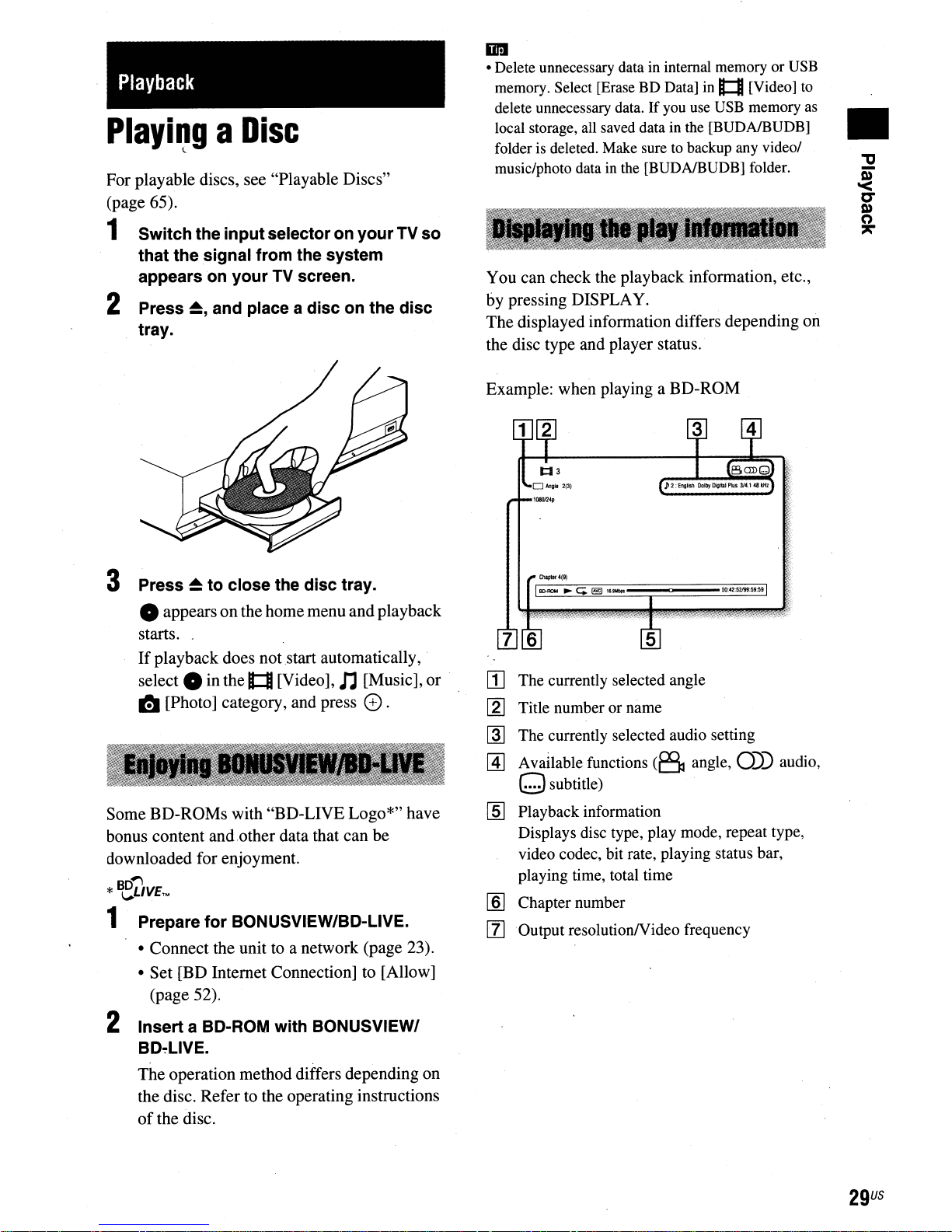
Example: when playing
C~llIr.(9)
Il[).fI()M
"C;~11."'*
aBO-ROM
7 6
[]
The currently selected angle
[2]
Title number or name
~
The currently selected audio setting
@]
Available functions
(6
angle,
osubtitle)
[ID
Playback information
Displays disc type, play mode, repeat type,
video codec, bit rate, playing status bar,
playing time, total time
lID
Chapter number
[Z]
Output resolutionNideo frequency
0))
audio,
2 Insert a BD-ROM with BONUSVIEWI
BD~lIVE.
The
operation method differs depending on
Refer
the disc.
of
the disc.
to the operating instructions
29
US
 Loading...