

Sokkia GSR1700 CSX Operation Manual

GNSS Receiver System
GSR1700 CSX
Operations Manual


GNSS Receiver System
Tplljb
GSR1700 CSX
Operations Manual

© 2008 POINT, Inc. All rights reserved.
Printed in the U.S.A.
The information in this document is subject to change without notice, and is
supplied without warranty of any kind. POINT, Inc. assumes no
responsibility or liability arising from the supply or use of the information in
this document.
No part of this publication may be reproduced, translated, stored in a
retrieval system, or transmitted in any form or means (electronic, photocopy,
record, or otherwise) without prior written permission from POINT, Inc. The
copyright laws of the United States of America and/or the jurisdiction where
you are located determine any limits or restrictions of your rights with regard
to this publication and the equipment.
®
SOKKIA
SDR
and Spectrum® are trademarks of SOKKIA TOPCON CO., LTD.
®
is a registered trademark of POINT, Inc. The following are trademarks
or registered trademarks of their respective organizations:
The Bluetooth® word mark and logos are owned by the Bluetooth SIG, Inc.
and any use of such marks by POINT, Inc. is under license.
®
CompactFlash
is a registered trademark of SanDisk Corporation.
Pulse Aperture Correlator (PAC)™ is a trademark of NovAtel Inc.
All other product and brand names are trademarks or registered trademarks
of their respective holders.
POINT, Inc.
16900 West 118th Terrace
Olathe, Kansas 66061 U.S.A.
www.point-inc.com
OM-1700CSX
Part number: 750-1-0077
Rev 2
03 DEC 2008

⚠
Notices
The following symbols are used in this manual:
This symbol alerts you to possible sources of difficulty or situations that
may cause damage to the product or accessories if proper precautions
are not followed.
This symbol directs your attention to important operating instructions.
This symbol indicates helpful tips about effectively using the product.
Usage Cautions
• This receiver incorporates circuitry to absorb most static discharges.
However, severe static shock may cause inaccurate operation of the
unit. Use anti-static precautions where possible.
• This device is a precision instrument. Although it is designed for
rugged operating conditions, it performs best when handled with
care.
• This receiver can accept an input supply voltage in the range of
6-18 VDC. Do not operate the receiver outside the specified voltage
range.
• When the battery compartment door is closed and latched, and the
port covers are closed, the enclosure is sealed to provide protection
against adverse environmental conditions. To minimize the
possibility of damage, keep the battery compartment door closed
and latched except when inserting or removing the battery, and
keep the ports covered except when they are in use.
• If you are using cables with the receiver, always use the correct
cables and handle them with care (do not pinch or bend them
sharply). Failure to do so may damage the receiver and void its
warranty.
i
CE Statement
ii

C-Tick Statement
NOTE
This device conforms to AS/NZS CISPR 22.
CISPR Statement
This device complies with CISPR 22 for Class B.
FCC Statement
This device complies with part 15 of the FCC Rules. Operation is subject to
the following two conditions: (1) This device may not cause harmful
interference, and (2) this device must accept any interference received,
including interference that may cause undesired operation.
This equipment has been tested and found to comply with the limits for a Class B
digital device, pursuant to part 15 of the FCC Rules. These limits are designed to
provide reasonable protection against harmful interference in a residential
installation. This equipment generates, uses and can radiate radio frequency energy
and, if not installed and used in accordance with the instructions, may cause harmful
interference to radio communications. However, there is no guarantee that
interference will not occur in a particular installation. If this equipment does cause
harmful interference to radio or television reception, which can be determined by
turning the equipment off and on, the user is encouraged to try to correct the
interference by one or more of the following measures:
• Reorient or relocate the receiving antenna.
• Increase the separation between the equipment and receiver.
• Connect the equipment into an outlet on a circuit different from that to which the
receiver is connected.
• Consult the dealer or an experienced radio/TV technician for help.
Warning: Changes or modifications to this equipment not expressly
approved by POINT, Inc. could result in a violation of Part 15 of the FCC
Rules and void the user’s authority to operate this equipment.
This device contains transmitter module FCC ID: ED9LMX9838.
RoHS Statement
This device complies with the European Union (EU) Restriction of Hazardous
Substances (RoHS) Directive 2002/95/EC.
iii

WEEE Notice
If you purchased your GSR1700 CSX in Europe, you must return it
to your dealer or supplier at the end of its life. The objectives of the
European Community's environment policy are, in particular, to
preserve, protect and improve the quality of the environment,
rationally. Sustainable development advocates the reduction of wasteful
consumption of natural resources and the prevention of pollution. Waste
electrical and electronic equipment (WEEE) is a regulated area. Where the
generation of waste cannot be avoided, it should be reused or recovered for
its material or energy. WEEE products may be recognized by their wheeled
bin label.
protect human health and utilize natural resources prudently and
iv

Contents
Chapter 1: Introduction 1
1.1 About the GSR1700 CSX.................................................1
1.2 Features ...........................................................................1
1.3 System Components ........................................................2
1.4 Find More Information ......................................................4
1.5 Technical Assistance........................................................5
Chapter 2: Receiver Components 6
2.1 Enclosure Overview .........................................................6
2.2 Ports .................................................................................7
2.2.1 Communication port ....................................................... 8
2.2.2 Power port ...................................................................... 8
2.2.3 Cable usage ...................................................................8
2.3 Quick Release Mount .....................................................10
2.4 Antenna ..........................................................................10
2.5 Battery ............................................................................10
2.5.1 Remove or insert the battery ........................................ 11
2.5.2 Charge the battery........................................................ 12
2.6 Memory ..........................................................................12
2.6.1 Remove the memory card ............................................ 13
2.6.2 Insert the memory card ................................................ 14
2.6.3 Format a memory card.................................................14
2.7 Wireless Communication................................................15
Chapter 3: Receiver Interface 16
3.1 Display Panel Overview .................................................16
3.2 Power Button..................................................................17
3.3 Gauges...........................................................................20
3.3.1 Battery life gauge ......................................................... 20
3.3.2 Satellite tracking gauge ................................................ 22
GSR1700 CSX Operations Manual v

Contents
3.3.3 Memory gauge.............................................................. 23
3.3.4 Occupation timer gauge ...............................................24
3.4 Status Indicators ............................................................ 26
3.4.1 Receiver health............................................................. 26
3.4.2 COM port communication status .................................. 29
3.4.3 Wireless communication status ....................................30
3.5 Audible Annunciator....................................................... 31
Chapter 4: System Setup 34
4.1 Setup Overview ............................................................. 34
4.2 Set Up at the Office ....................................................... 35
4.3 Set Up for Field Operations ........................................... 35
4.3.1 Typical static or stop-and-go/kinematic base setup...... 36
4.3.2 Typical stop-and-go/kinematic rover setup...................38
4.4 Measure Antenna Height ............................................... 40
4.4.1 Slant height method...................................................... 40
4.4.2 Vertical and true vertical height methods .....................42
Chapter 5: Power Management 44
5.1 Turn the Receiver On and Off........................................ 44
5.2 Use an External Power Source...................................... 44
5.3 Power Peripheral Devices.............................................. 45
5.4 Store the Receiver ......................................................... 45
5.5 Insufficient Power .......................................................... 45
Chapter 6: Collecting Data 47
6.1 Data Files....................................................................... 47
6.1.1 File names .................................................................... 47
6.1.2 Data storage capacity...................................................48
6.1.3 Erase stored files..........................................................49
6.2 Use a Data Collector...................................................... 49
6.3 Use the POWERUP Configuration................................. 50
6.3.1 About the POWERUP configuration .............................50
6.3.2 Default POWERUP configurations ............................... 50
vi GSR1700 CSX Operations Manual

6.3.3 Customizing POWERUP configurations....................... 51
6.3.4 Perform a factory reset................................................. 52
Appendix A: Technical Specifications 53
Index 57
Contents
GSR1700 CSX Operations Manual vii

Figures
1 Standard components and accessories ............................. 3
2 Optional components ......................................................... 4
3 Receiver components......................................................... 6
4 Ports ................................................................................... 7
5 Phase center offset label .................................................. 10
6 Display panel components .............................................. 16
7 Power button functions .................................................... 18
8 Typical base setup .......................................................... 36
9 Typical rover setup ........................................................... 38
10 Slant height method ........................................................ 41
11 Vertical/true vertical height methods ................................ 42
viii GSR1700 CSX Operations Manual

Tables
1 GSR1700 CSX features......................................................2
2 Standard component/accessory descriptions .....................3
3 Optional component descriptions........................................4
4 Receiver components .........................................................7
5 Port descriptions .................................................................8
6 Cables for GSR1700 CSX ..................................................9
7 Display panel components................................................16
8 Power button functions .....................................................18
9 Battery life gauge indicators..............................................21
10 Satellite tracking gauge indicators ....................................22
11 Memory gauge indicators..................................................23
12 Occupation timer gauge, baseline length mode................25
13 Occupation timer gauge, elapsed time mode ...................25
14 Temperature issues ..........................................................27
15 Voltage issues...................................................................27
16 Firmware issues................................................................28
17 COM ports communication status LEDs ...........................29
18 Wireless communication status LEDs...............................30
19 Audible annunciator conditions .........................................31
20 Base setup components ...................................................36
21 Rover setup components ..................................................39
22 Slant height method ..........................................................41
23 Vertical/true vertical height methods.................................43
24 Auto-generated file name convention ...............................47
25 Hours of storage ...............................................................48
GSR1700 CSX Operations Manual ix

Tables
26 POWERUP configurations ............................................... 51
27 GSR1700 CSX technical specifications ........................... 53
x GSR1700 CSX Operations Manual

Chapter 1: Introduction
This manual provides complete information about your
GSR1700 CSX receiver and its functions, including components,
system setup, and data collection.
1.1 About the GSR1700 CSX
The GSR1700 CSX is a compact, lightweight, high performance
receiver system incorporating an L1 GPS+GLONASS receiver,
integrated antenna, memory, battery, and Bluetooth
in a rugged enclosure.
The receiver is ideal for static and stop-and-go/kinematic
surveying applications. It is completely wireless and fits
conveniently on the pole or tripod.
You can simply mount the receiver on a tripod or rover pole,
press the power button, and begin collecting raw data. You can
also add the SDR+ data collection software to your setup in the
field.
®
connectivity
1.2 Features
The GSR1700 CSX is capable of the following modes of operation:
• Static post-processing
• Stop-and-go kinematic post-processing
• Autonomous navigation
•SBAS-enabled navigation
GSR1700 CSX Operations Manual 1

Chapter 1 Introduction
GSR1700 CSX features are summarized in Table 1. For technical
specifications, see Appendix A, Technical Specifications,
page 53.
Table 1: GSR1700 CSX features
28 universal channels: 14 L1 GPS, 12 L1 GLONASS, 2 SBAS
Patented Pulse Aperture Correlator (PAC)™ technology for high-accuracy
GNSS measurement and multipath rejection
Multiple Bluetooth wireless connectivity
Multiple language voice messages or sounds to indicate receiver status
One-button survey operation
Easy-to-read LED display status indicators
Rugged, shock-resistant, waterproof, buoyant enclosure
RoHS compliant
Cable-free setup
“Hot swappable” rechargeable batteries
64 MB removable CompactFlash
®
memory card (options up to 2 GB available)
Accepts input from RTCM1 (RTCM-DGPS) sources
1.3 System Components
When you receive your GSR1700 CSX system, ensure that you
have received all of the components. Standard system
components and accessories are shown and described on page 3.
Optional components are shown and described on page 4.
2 GSR1700 CSX Operations Manual
Introduction Chapter 1
1
4
3
6
7
8
9
2
5
11
12
10
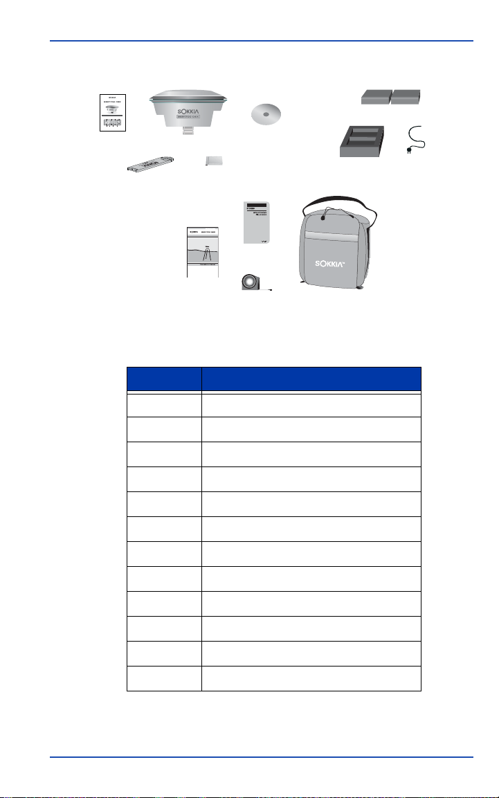
Figure 1: Standard components and accessories
GNSS Receiver System
At A Glance
LED Display Panel
Receiver
Occupation
COM Port
Satellite
Health
Timer
Status
Tracking
®
Bluetooth
Power
Battery
Memory
Status
Button
Life
Table 2: Standard component/accessory descriptions
Number Description
1 GNSS receiver
2 GSR1700 CSX At A Glance
3 Measuring bar
4 Memory card
5 GSR Family Tools CD
6 Batteries (2)
7 Battery charger
8 Battery charger cable
9 Operations Manual
GSR1700 CSX Operations Manual 3
10 GPS Field Book
11 Tape measure
12 Soft carrying case
Chapter 1 Introduction
1
2
3
4
5
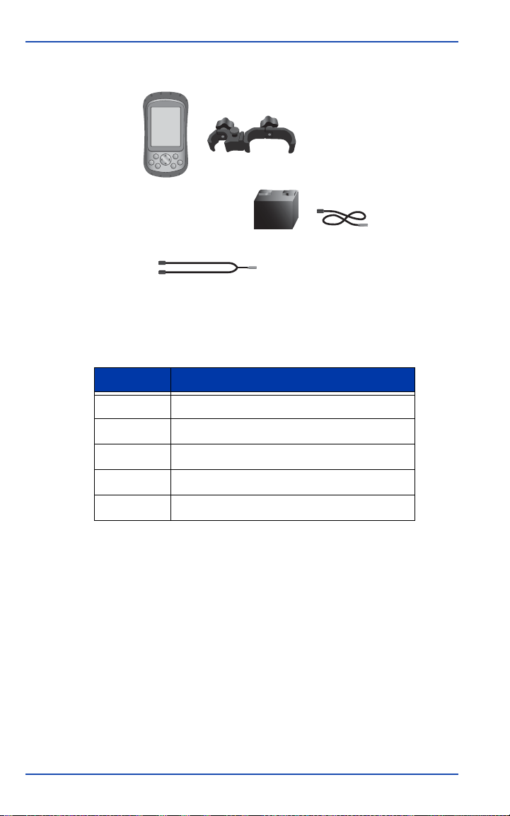
Figure 2: Optional components
Table 3: Optional component descriptions
Number Description
1 Data collector
2 Data collector mounting bracket
3 External battery
4 External battery cable
5 Communications cables (various)
1.4 Find More Information
The following documentation provides supporting information
to this manual:
• GSR1700 CSX Quick Reference Guide. Provides typical
workflows for getting started using the GSR1700 CSX survey
system and Spectrum Survey.
4 GSR1700 CSX Operations Manual

Introduction Chapter 1
• SDR+ User Guide and Help. Describe how to use the SDR+ data
collection software.
• Receiver Bluetooth Setup Quick Reference Guide. Describes how
to configure Bluetooth settings on handheld controllers and
PCs to establish connections to SOKKIA receivers.
• Planning User Guide and Help. Describe how to use Planning
software, including determining satellite availability and
editing configurations.
• Spectrum Survey User Guide and Help. Describe how to process
and adjust your data using Spectrum Survey software.
1.5 Technical Assistance
Technical support is available from the distributor where you
purchased this product. When you contact technical support,
please make sure you have the following information:
• Your receiver information, including serial number, part
number, model, and firmware version
• A descriptive and concise explanation of the problem
For information about SOKKIA TOPCON worldwide offices, see
the list at the back of this manual.
GSR1700 CSX Operations Manual 5
Chapter 2: Receiver Components
1
2
3
4
5
6
The GSR1700 CSX enclosure is fully sealed and houses your
system’s GNSS receiver, antenna, batteries, memory, and wireless
communication device.
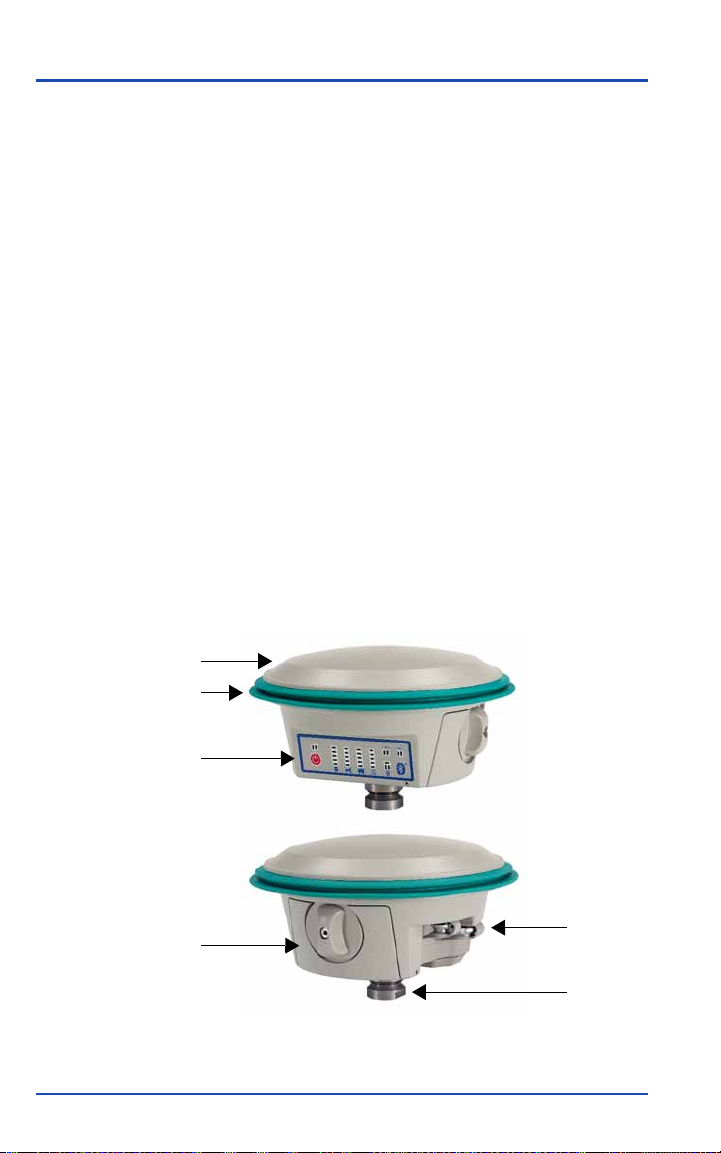
2.1 Enclosure Overview
The receiver’s antenna is enclosed by the radome, which is
surrounded by a shock-absorbing rubber bumper.
The easy-to-use display panel incorporates single-button
operation and LED indicators that give you a view of your
system status. For details about the display panel features and
how to use them, see Chapter 3, Receiver Interface, page 16.
The battery compartment door provides access to the battery and
the memory card.
Figure 3: Receiver components
6 GSR1700 CSX Operations Manual
Receiver Components Chapter 2
1
2
Table 4: Receiver components
Component Description
1 Radome
2 Bumper
3 Display panel
4 Battery compartment
5 Ports
6 Quick release mount
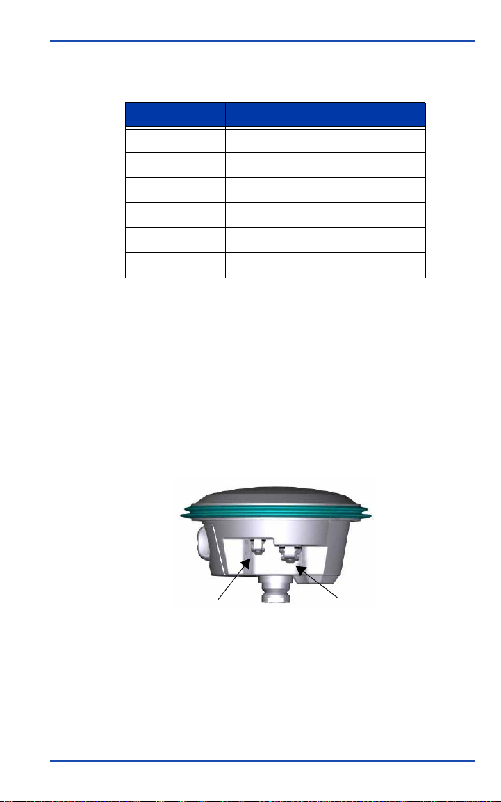
2.2 Ports
The receiver features an external power input port and a
communication port. Each port is labelled for easy identification
(see Table 5, Port descriptions, page 8).
Both ports are protected from dust and water by attached covers.
You should leave these port covers closed whenever the ports are
not in use.
Figure 4: Ports
GSR1700 CSX Operations Manual 7
Chapter 2 Receiver Components
NOTE
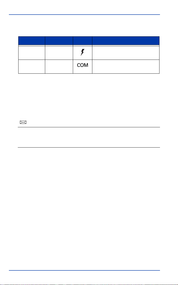
Table 5: Port descriptions
Number Port Icon Description
1 Power Power input port
2 COM1 Communication port for accessory
devices
2.2.1 Communication port
Use the receiver’s communication port (COM1) to communicate
with a data collector or other accessory devices. The COM1 port
can also provide power output for powering external devices (see
Section 5.3, Power Peripheral Devices, page 45).
If you will be using both a radio and a wired data collector, contact your
distributor for the appropriate cable that enables the COM1 port to
operate simultaneously as two COM ports (COM1 and COM2).
2.2.2 Power port
The receiver features one power input port for connecting an
external power source to the receiver, such as using an external
battery as an alternative to the receiver’s battery.
2.2.3 Cable usage
When you are using cables, ensure that you follow the
instructions in this section.
The cables shown in Table 6, Cables for GSR1700 CSX, page 9, are
compatible with the GSR1700 CSX.
8 GSR1700 CSX Operations Manual

Receiver Components Chapter 2
CAUTION
⚠
CAUTION
⚠
Table 6: Cables for GSR1700 CSX
Cable Part number
High power/base station Satel UHF cable 403-0-0015
Serial to DB9 cable 403-0-0036
“Y” serial cable (COM1 and COM2) 403-0-60565003
Satel UHF cable 403-0-0058
Raven AirLink cable 402-0-9083
Do not use the GSR2700 IS/ISX PC USB cable (part number
403-0-0146) with the GSR1700 CSX. It is not approved for use with
this receiver.
To prevent damage to the receiver and the cables, each cable
connector is keyed to ensure that the cable can be inserted in only
one way. Connectors also have a latching mechanism that
requires careful insertion and removal from ports.
Observe the following guidelines when using cables:
1. Line up the red dot on the cable connector shell with the red
index mark on the port.
2. Insert the connector until it seats with a click. It will then be
locked in place.
3. To remove a cable, grasp the connector and pull straight out.
If there is a knurled ring, grasp it and pull.
Do not pull directly on the cable.
GSR1700 CSX Operations Manual 9
 Loading...