


GCX3
GNSS Receiver
Operator’s Manual

GCX3
GNSS Receiver
Operator’s Manual
Part Number 1016293-01
Revision B
All contents in this manual are copyrighted by Sokkia®. All rights reserved
© Copyright Sokkia
February, 2017

Table of Contents
Preface . . . . . . . . . . . . . . . . . . . . . . . . . . . . . . . . . . . . . . . . . . . . . . . . . . . . iv
Introduction
Acronyms and Terminology Used in this Operator’s Manual . . . . . . . . . . . . . 2
GCX3 Features . . . . . . . . . . . . . . . . . . . . . . . . . . . . . . . . . . . . . . . . . . . . . . . . . 2
Unpacking Your Receiver Kit . . . . . . . . . . . . . . . . . . . . . . . . . . . . . . . . . . . . . . 3
System Components . . . . . . . . . . . . . . . . . . . . . . . . . . . . . . . . . . . . . . . . . . . 3
Technical Documents . . . . . . . . . . . . . . . . . . . . . . . . . . . . . . . . . . . . . . . . . . . . 4
Using Sokkia Receiver Utility Software with Your Receiver . . . . . . . . . . . . . 4
Getting Technical Support . . . . . . . . . . . . . . . . . . . . . . . . . . . . . . . . . . . . . . . . 4
Website . . . . . . . . . . . . . . . . . . . . . . . . . . . . . . . . . . . . . . . . . . . . . . . . . . . . 5
. . . . . . . . . . . . . . . . . . . . . . . . . . . . . . . . . . . . . . . . . . . . . . . . . . . . . . . . . . . . 1
Getting Acquainted . . . . . . . . . . . . . . . . . . . . . . . . . . . . . . . . . . . . . . . . . . 6
Receiver Overview . . . . . . . . . . . . . . . . . . . . . . . . . . . . . . . . . . . . . . . . . . . . . . 6
Cable and Adapters . . . . . . . . . . . . . . . . . . . . . . . . . . . . . . . . . . . . . . . . . . . . 6
Drivers . . . . . . . . . . . . . . . . . . . . . . . . . . . . . . . . . . . . . . . . . . . . . . . . . . . . . 8
Memory . . . . . . . . . . . . . . . . . . . . . . . . . . . . . . . . . . . . . . . . . . . . . . . . . . . . 8
Internal Battery. . . . . . . . . . . . . . . . . . . . . . . . . . . . . . . . . . . . . . . . . . . . . . . 8
Long-Range Bluetooth Technology . . . . . . . . . . . . . . . . . . . . . . . . . . . . . . . . . 8
Micro-AB USB Port Panel . . . . . . . . . . . . . . . . . . . . . . . . . . . . . . . . . . . . . . . . 9
Display Panel Operations . . . . . . . . . . . . . . . . . . . . . . . . . . . . . . . . . . . . . 10
LED Icon Key . . . . . . . . . . . . . . . . . . . . . . . . . . . . . . . . . . . . . . . . . . . . . . . . . . 10
Power Button (PWR) . . . . . . . . . . . . . . . . . . . . . . . . . . . . . . . . . . . . . . . . . . . . 11
Receiver Status LEDs . . . . . . . . . . . . . . . . . . . . . . . . . . . . . . . . . . . . . . . . . . . . 13
Satellite Tracking Status (STAT) LED. . . . . . . . . . . . . . . . . . . . . . . . . . . . . . . . 13
Recording and Memory LED (REC) . . . . . . . . . . . . . . . . . . . . . . . . . . . . . . . . . 14
Bluetooth Communication LED (BT) . . . . . . . . . . . . . . . . . . . . . . . . . . . . . . . . 14
Battery LED (BATT) . . . . . . . . . . . . . . . . . . . . . . . . . . . . . . . . . . . . . . . . . . . . 15
Managing Power . . . . . . . . . . . . . . . . . . . . . . . . . . . . . . . . . . . . . . . . . . . . 16
Turning the Receiver ON/OFF . . . . . . . . . . . . . . . . . . . . . . . . . . . . . . . . . . . . . 16
Using Internal and External Power Sources. . . . . . . . . . . . . . . . . . . . . . . . . . 16
Internal Battery. . . . . . . . . . . . . . . . . . . . . . . . . . . . . . . . . . . . . . . . . . . . . . . 16
Charging the Battery . . . . . . . . . . . . . . . . . . . . . . . . . . . . . . . . . . . . . . . . . . . 17
Power Accessories . . . . . . . . . . . . . . . . . . . . . . . . . . . . . . . . . . . . . . . 18
Insufficient Power . . . . . . . . . . . . . . . . . . . . . . . . . . . . . . . . . . . . . . . . . . . . . . 18
Tab le o f Co nt ent s
P/N: 1016293-01
i

Configuring the Receiver . . . . . . . . . . . . . . . . . . . . . . . . . . . . . . . . . . . . . 19
Before You Begin Configuring the Receiver . . . . . . . . . . . . . . . . . . . . . . . . . . 19
Viewing Receiver Information. . . . . . . . . . . . . . . . . . . . . . . . . . . . . . . . . . . . . 19
Open the Receiver Info Window . . . . . . . . . . . . . . . . . . . . . . . . . . . . . . . . . . . 19
Loading New Firmware . . . . . . . . . . . . . . . . . . . . . . . . . . . . . . . . . . . . . . . . . . 20
Uploading Firmware Files to the Receiver. . . . . . . . . . . . . . . . . . . . . . . . . . . . . 20
Optional Authorization Files (OAFs) . . . . . . . . . . . . . . . . . . . . . . . . . . . . . . . . 24
Checking the Receiver’s OAFs. . . . . . . . . . . . . . . . . . . . . . . . . . . . . . . . . . . . . 24
Viewing Receiver Options Using the Sokkia Receiver Utility (SRU) . . . . . . 24
Loading an OAF. . . . . . . . . . . . . . . . . . . . . . . . . . . . . . . . . . . . . . . . . . . . . . . 25
Loading a New OAF . . . . . . . . . . . . . . . . . . . . . . . . . . . . . . . . . . . . . . 25
Resetting the Receiving (Clearing) NVRAM . . . . . . . . . . . . . . . . . . . . . . . . . . 29
Clearing NVRAM Using Sokkia Receiving Utility (SRU) . . . . . . . . . . . . . . . . . . . . 29
System Setup . . . . . . . . . . . . . . . . . . . . . . . . . . . . . . . . . . . . . . . . . . . . . . . 30
Setting Up the Base Receiver . . . . . . . . . . . . . . . . . . . . . . . . . . . . . . . . . . . . . 30
Table of Contents
Setting Up the Rover Receiver . . . . . . . . . . . . . . . . . . . . . . . . . . . . . . . . . . . . 31
Measuring Antenna Height . . . . . . . . . . . . . . . . . . . . . . . . . . . . . . . . . . . . . . . 32
Obtaining Accurate Antenna Height. . . . . . . . . . . . . . . . . . . . . . . . . . . . . . . . . 32
Collecting Data . . . . . . . . . . . . . . . . . . . . . . . . . . . . . . . . . . . . . . . . . . . . . 33
Collecting Data . . . . . . . . . . . . . . . . . . . . . . . . . . . . . . . . . . . . . . . . . . . . . . . . . 33
Setting Recording Parameters. . . . . . . . . . . . . . . . . . . . . . . . . . . . . . . . . . . . . 33
Log Rates . . . . . . . . . . . . . . . . . . . . . . . . . . . . . . . . . . . . . . . . . . . . . . . . . . . 33
Record Data . . . . . . . . . . . . . . . . . . . . . . . . . . . . . . . . . . . . . . . . . . . . . . . . . 33
Start/Stop Recording Using LED Display Panel or SRU. . . . . . . . . . . . . . . . . . . . 33
File Management. . . . . . . . . . . . . . . . . . . . . . . . . . . . . . . . . . . . . . . . . . . . . . 34
Downloading and Deleting Files . . . . . . . . . . . . . . . . . . . . . . . . . . . . . . 34
Troubleshooting . . . . . . . . . . . . . . . . . . . . . . . . . . . . . . . . . . . . . . . . . . . . . 35
Check this First. . . . . . . . . . . . . . . . . . . . . . . . . . . . . . . . . . . . . . . . . . . . . . . . . 35
Powering Problems . . . . . . . . . . . . . . . . . . . . . . . . . . . . . . . . . . . . . . . . . . . . . 36
Receiver Does Not Power Up . . . . . . . . . . . . . . . . . . . . . . . . . . . . . . . . . . . . . 36
Additional Receiver Problems . . . . . . . . . . . . . . . . . . . . . . . . . . . . . . . . . . . . . 36
Generic Problems . . . . . . . . . . . . . . . . . . . . . . . . . . . . . . . . . . . . . . . . 37
No Long Term Lock on Satellites. . . . . . . . . . . . . . . . . . . . . . . . . . . . . . . . . . . 37
Too Few Satellites Tracked. . . . . . . . . . . . . . . . . . . . . . . . . . . . . . . . . . . . . . . 38
No Code Differential and/or Real Time Kinematic (RTK) Solutions Obtained . . . . 39
Receiver Does Not Log Data. . . . . . . . . . . . . . . . . . . . . . . . . . . . . . . . . . . . . . 40
Tab le o f Co nt ent s
P/N: 1016293-01
ii

Bluetooth Problems . . . . . . . . . . . . . . . . . . . . . . . . . . . . . . . . . . . . . . . . . . . . . 41
SRU Error Message—Can’t Find Receiver . . . . . . . . . . . . . . . . . . . . . . . . . . . . . 41
No Available Devices Discovered . . . . . . . . . . . . . . . . . . . . . . . . . . . . . . . . . . . 42
Receiver Bluetooth Icon Visible—Cannot Establish Connection . . . . . . . . . . . . . . 42
Long-Range Connection Problems . . . . . . . . . . . . . . . . . . . . . . . . . . . . . . . . . 43
Long-Range Connections—Cannot Discover the Base Receiver. . . . . . . . . . . . . . 43
Cannot Establish a Bluetooth Connection . . . . . . . . . . . . . . . . . . . . . . . . . . . . . 43
Sokkia Receiver Utility (SRU) Problems . . . . . . . . . . . . . . . . . . . . . . . . . . . . . 44
SRU Cannot Connect to Receiver . . . . . . . . . . . . . . . . . . . . . . . . . . . . . . . . . . 44
Cleaning and Storing the Receiver . . . . . . . . . . . . . . . . . . . . . . . . . . . . . . . . . 44
Getting Customer Support. . . . . . . . . . . . . . . . . . . . . . . . . . . . . . . . . . . . . . . . 44
Specifications . . . . . . . . . . . . . . . . . . . . . . . . . . . . . . . . . . . . . . . . . . . . . . . 45
General Details. . . . . . . . . . . . . . . . . . . . . . . . . . . . . . . . . . . . . . . . . . . . . . . . . 45
Safety Warnings . . . . . . . . . . . . . . . . . . . . . . . . . . . . . . . . . . . . . . . . . . . . 49
General Warnings . . . . . . . . . . . . . . . . . . . . . . . . . . . . . . . . . . . . . . . . . . . . . . 49
Table of Contents
Battery Warnings . . . . . . . . . . . . . . . . . . . . . . . . . . . . . . . . . . . . . . . . . . . . . . . 49
Receiver Warnings . . . . . . . . . . . . . . . . . . . . . . . . . . . . . . . . . . . . . . . . . . . . . . 49
Usage Warnings . . . . . . . . . . . . . . . . . . . . . . . . . . . . . . . . . . . . . . . . . . . . . . . 49
Regulatory . . . . . . . . . . . . . . . . . . . . . . . . . . . . . . . . . . . . . . . . . . . . . . . . . 50
FCC Compliance . . . . . . . . . . . . . . . . . . . . . . . . . . . . . . . . . . . . . . . . . . . . . . . . 50
Industry Canada Compliance . . . . . . . . . . . . . . . . . . . . . . . . . . . . . . . . . . . . . 50
Community of Europe Compliance . . . . . . . . . . . . . . . . . . . . . . . . . . . . . . . . . 51
European Community Declaration of Conformity with R&TTE Directive 1999/5/EC 51
Declaration of Conformity (R&TTE Directive 1999/5/EC) . . . . . . . . . . . . . . . 52
Waste Electrical and Electronic Equipment (WEEE) Directive . . . . . . . . . . . . 53
Bluetooth Transmission Statements/Compliance . . . . . . . . . . . . . . . . . . . . . 53
Korean KC-RF Compliance . . . . . . . . . . . . . . . . . . . . . . . . . . . . . . . . . . . . . . . . 54
Japan Radio Law and Telecommunications Business Law Compliance. . . . . 54
Bluetooth Module Compliance. . . . . . . . . . . . . . . . . . . . . . . . . . . . . . . . . . . . . 54
Warranty . . . . . . . . . . . . . . . . . . . . . . . . . . . . . . . . . . . . . . . . . . . . . . . . . . 55
Tab le o f Co nt ent s
P/N: 1016293-01
iii

Preface
Thank you for purchasing this Sokkia® product. The materials available in this Manual (the “Manual”) have been prepared by
Topcon Positioning SystemsTM, Incorporated. (“TPS”) for owners of Sokkia products, and are designed to assist owners with
the use of the receiver and its use is subject to these terms and conditions (the “Terms and Conditions”).
Please read the terms and conditions carefully.
Terms and Conditions
Use
This product is designed to be used by a professional. The user should have a good knowledge of the safe use of the product
and implement the types of safety procedures recommended by the local government protection agency for both private use
and commercial job sites.
Copyrights
All information contained in this Manual is the intellectual property of, and copyrighted material of TPS. All rights are reserved.
Do not use, access, copy, store, display, create derivative works of, sell, modify, publish, distribute, or allow any third party
access to, any graphics, content, information or data in this Manual without TPS’ express written consent and may only use
such information for the care and operation of the receiver. The information and data in this Manual are a valuable asset of
TPS and are developed by the expenditure of considerable work, time and money, and are the result of original selection,
coordination and arrangement by TPS.
Trademarks
GCX3TM, MagnetTM, Sokkia®, LongLinkTM, POSTTM (Precision Orbital Satellite Technology), Topcon and Topcon Positioning
Systems
Microsoft® Corporation. The Bluetooth® word mark and logos are owned by Bluetooth® SIG, Inc. and any use of such marks
by Topcon Positioning SystemsTM, Incorporated is used under license. Other product and company names mentioned herein
may be trademarks of their respective owners.
TM
are trademarks or registered trademarks of Topcon Positioning SystemsTM. Windows® is a registered trademark of
Disclaimer of Warranty
EXCEPT FOR ANY WARRANTIES IN AN APPENDIX OR A WARRANTY CARD ACCOMPANYING THE PRODUCT, THIS MANUAL
AND THE RECEIVER ARE PROVIDED “AS-IS.” THERE ARE NO OTHER WARRANTIES. TPS DISCLAIMS ANY IMPLIED WARRANTY
OF MERCHANTABILITY OR FITNESS FOR ANY PARTICULAR USE OR PURPOSE. TPS AND ITS DISTRIBUTORS SHALL NOT BE
LIABLE FOR TECHNICAL OR EDITORIAL ERRORS OR OMISSIONS CONTAINED HEREIN; NOR FOR INCIDENTAL OR
CONSEQUENTIAL DAMAGES RESULTING FROM THE FURNISHING, PERFORMANCE OR USE OF THIS MATERIAL OR THE
RECEIVER. SUCH DISCLAIMED DAMAGES INCLUDE BUT ARE NOT LIMITED TO LOSS OF TIME, LOSS OR DESTRUCTION OF
DATA, LOSS OF PROFIT, SAVINGS OR REVENUE, OR LOSS OF THE PRODUCT’S USE. IN ADDITION TPS IS NOT RESPONSIBLE
OR LIABLE FOR DAMAGES OR COSTS INCURRED IN CONNECTION WITH OBTAINING SUBSTITUTE PRODUCTS OR
SOFTWARE, CLAIMS BY OTHERS, INCONVENIENCE, OR ANY OTHER COSTS. IN ANY EVENT, TPS SHALL HAVE NO LIABILITY
FOR DAMAGES OR OTHERWISE TO YOU OR ANY OTHER PERSON OR ENTITY IN EXCESS OF THE PURCHASE PRICE FOR THE
RECEIVER.
License Agreement
Use of any computer programs or software supplied by TPS or downloaded from a TPS website (the “Software”) in connection
with the receiver constitutes acceptance of these Terms and Conditions in this Manual and an agreement to abide by these
Terms and Conditions. The user is granted a personal, non-exclusive, non-transferable license to use such Software under the
terms stated herein and in any case only with a single receiver or single computer. You may not assign or transfer the Software
or this license without the express written consent of TPS. This license is effective until terminated. You may terminate the
license at any time by destroying the Software and Manual. TPS may terminate the license if you fail to comply with any of the
Preface
P/N: 1016293-01
iv
Terms or Conditions. You agree to destroy the Software and manual upon termination of the use of the receiver. All
ownership, copyright and other intellectual property rights in and to the Software belong to TPS. If these license terms are
not acceptable, return any unused software and manual.
Confidentiality
This Manual, its contents, and the Software (collectively, the “Confidential Information”) are the confidential and proprietary
information of TPS. You agree to treat TPS’ Confidential Information with a degree of care no less stringent that the degree
of care you would use in safeguarding your own most valuable trade secrets. Nothing in this paragraph shall restrict you
from disclosing Confidential Information to your employees as may be necessary or appropriate to operate or care for the
receiver. Such employees must also keep the Confidentiality Information confidential. In the event you become legally
compelled to disclose any of the Confidential Information, you shall give TPS immediate notice so that it may seek a
protective order or other appropriate remedy.
Website and Other Statements
No statement contained at the TPS website (or any other website) or in any other advertisements or TPS literature or made
by an employee or independent contractor of TPS modifies these Terms and Conditions (including the Software license,
warranty and limitation of liability).
Safety
Improper use of the receiver can lead to injury to persons or property and/or malfunction of the product. The receiver should
only be repaired by authorized TPS warranty service centers.
Preface
Miscellaneous
The above Terms and Conditions may be amended, modified, superseded, or canceled at any time by TPS. The Terms and
Conditions will be governed by, and construed in accordance with the laws of the State of California, without reference to
conflict of laws.
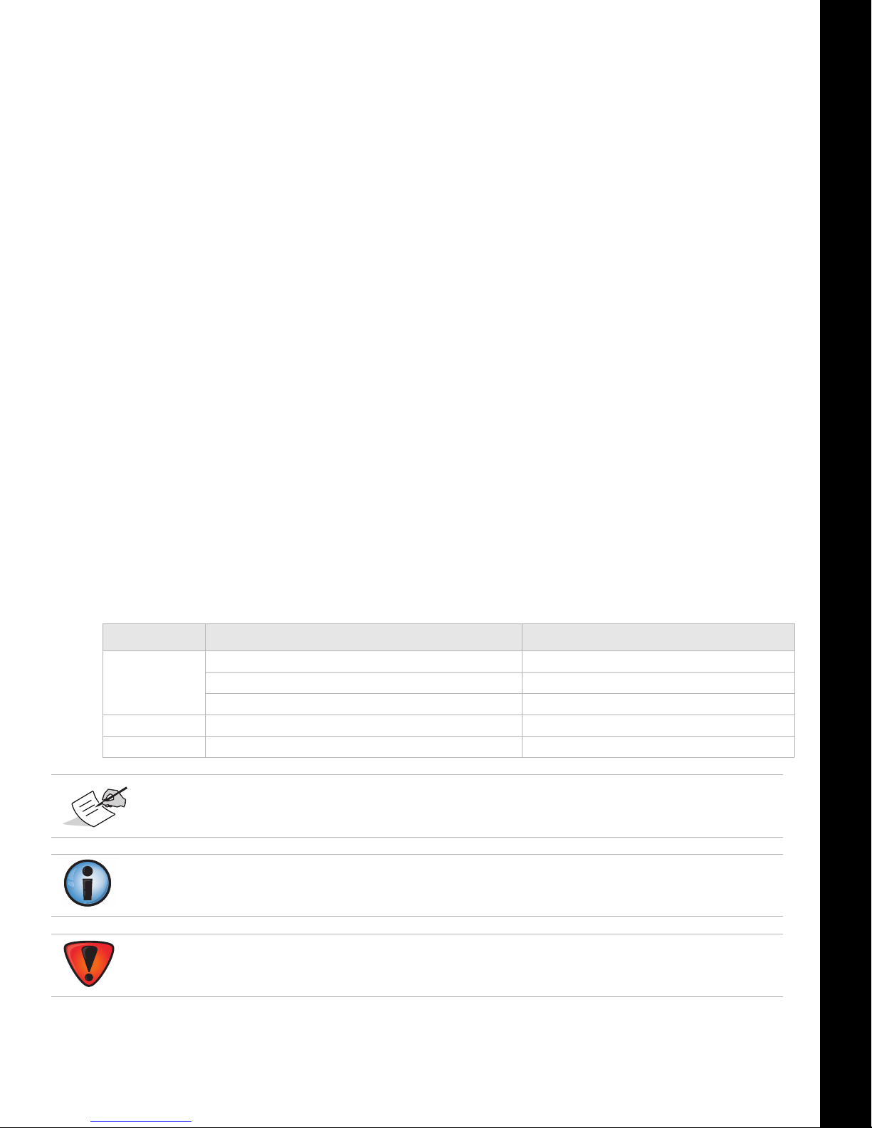
Manual Conventions
This manual uses the following conventions:
Convention Description Example
Bold Menu, or drop-down menu selection FileExit (Click the File menu and click Exit)
Name of a dialog box or screen From the Connection screen...
Button or key commands Click Finish.
Mono User supplied text or variable Type guest, and click Enter.
Italic
Further information to note about system configuration, maintenance, or setup.
Supplementary information that can have an adverse effect on system operation, system
performance, data integrity, measurements, or personal safety.
Reference to another manual or help document Refer to the
Topcon Reference Manual.
Notification that an action has the potential to result in system damage, loss of data, loss of
warranty, or personal injury.
Preface
P/N: 1016293-01
v
Introduction
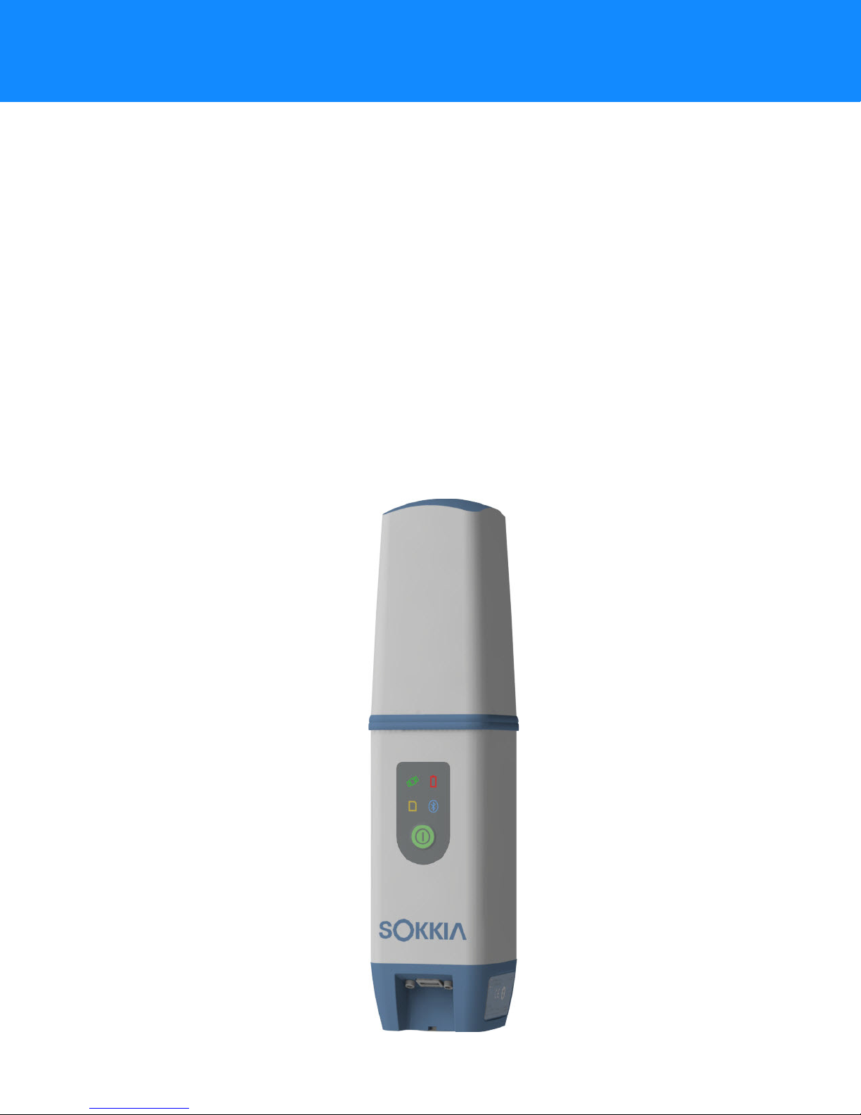
The Sokkia GCX3 receiver (Figure 1) is a compact, lightweight, and completely integrated GNSS receiver
for static and cable-free stop and go/kinematic applications. The integrated receiver design includes a
GNSS receiver board, based on industry-leading technology, internal long-life batteries, memory
storage, and Long-Range Bluetooth communication technology. The GCX3 delivers world-class
positioning and navigation capability to your application by tracking signals from multi-constellation
satellite systems, including GPS, GLONASS, Galileo, BeiDou, and SBAS (
The GCX3 includes Sokkia’s exclusive Long-Range Bluetooth Technology, which provides the perfect
solution for short range job sites that require RTK communication. The GCX3 can be paired with a
cellular-enabled data collector to receive corrections from an Ntrip Caster for rover operation. This setup
can also be used with MAGNET
MAGNET Relay configuration enables you to operate up to three (3) GCX3 rovers with a single GCX3
receiver.
The GCX3 offers complete IP67 protection against dust and water ingress, in addition to superior
vibration and shock resistance. The Sokkia communication interface enables you to quickly integrate
Sokkia’s premium GNSS performance within new systems and quickly deliver world-class positioning
and navigation support to your applications.
Tab le 1).
TM
Relay for a cost effective RTK base solution over long distances. The
Introduction
Figure 1: GCX3 Receiver
P/N: 1016293-01
1
Acronyms and Terminology Used in this Operator’s Manual
Table 1. Acronyms, Terminology and Definitions
Acronym/Terms Definition/Description
Introduction
DGPS
GNSS
IP67
MINTER
Ntrip
OAF
RTK
SBAS
Differential Global Positioning System—DGPS augments
standalone GPS positioning by using modeled corrections to
improve location accuracy.
Global Navigation Satellite System
IEC Standard 60529—describes complete Ingress Protection (IP)
against dust and water submersion.
A membrane switch overlay with LED indicators and or soft keys.
Sometimes referred to as a front panel or an interface.
Networked Transport of RTCM via Internet Protocol (Ntrip)—a
protocol for streaming differential GPS (DGPS) data over the
Internet in accordance with specification published by RTCM.
Option Authorization File—An OAF is used in software to lock or
unlock features specific features to the user.
Real Time Kinematic—is a differential GNSS technique that
provides high performance positioning in the vicinity of a base
station.
Satellite-Based Augmentation System—SBAS supports wide-area
or regional augmentation through the use of additional satellitebroadcast messages. Such systems are commonly composed of
multiple ground stations, located at accurately-surveyed points.
SRU
GCX3 Features
The GCX3 receiver’s advanced design eliminates the need for cables during operation, allowing for a
simplified setup and less parts to keep track of. The GCX3 receiver features the following:
• Compact, lightweight, and rugged design
• A premier multi-constellation GNSS board featuring industry leading technology
• Integrated multi-channel Long-Range Bluetooth Technology
• Internal memory for data storage
• One internal battery, providing all day operation under normal operating conditions
• A highly visible display panel with single-button operation
• One USB port for communications and power
Sokkia Receiver Utility—SRU software is used to configure GNSS
antennas and radios.
Acronyms and Terminology Used in this Operator’s Manual
P/N: 1016293-01
2
You can configure the GCX3 receiver in a variety of ways, depending on your project requirements.
Typically, the receiver supports the following operation modes.
• Static/post-processing data collection
• Job site RTK using Long-Range Bluetooth Technology
• Network Rover for DGPS and RTK operation
• MAGNET Relay operation
• SBAS-enabled operation
Unpacking Your Receiver Kit
This section describes the documentation, standard kit components, and accessories (depending on
your purchase) that accompany your receiver. When you unpack your receiver kit, verify you received
the items listed in this section. Make sure the items do not appear damaged from shipment. If any of
the items are missing or damaged, contact your Sokkia dealer or Sokkia
“Getting Technical Support” on page 4.
• Receiver components are shown in Figure 2.
• Receiver documentation is listed in “Technical Documents” on page 4.
technical support. See
Introduction
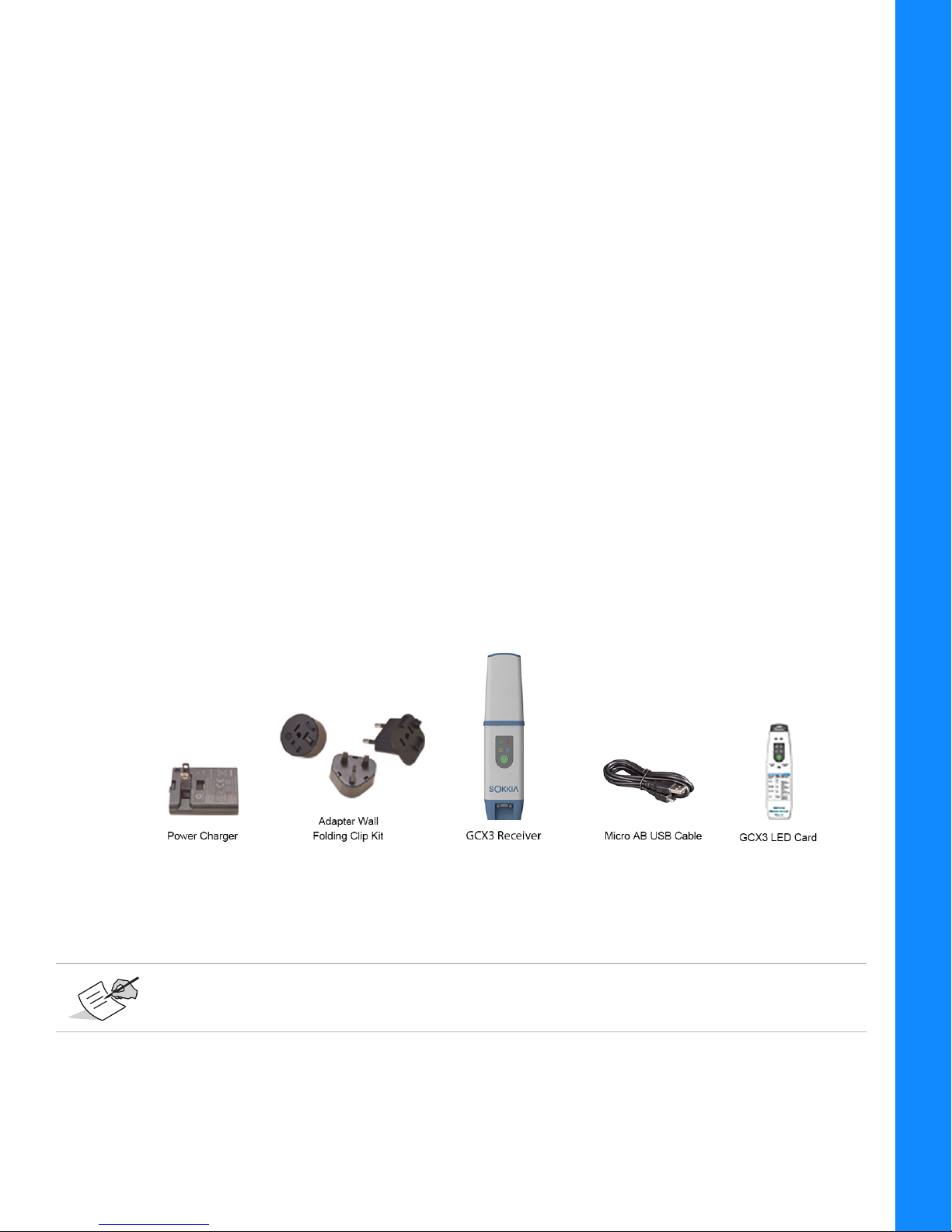
System Components
The items shown Figure 2 in are shipped with your receiver.
Figure 2: System Components
Utility software for the GCX3 receiver may be downloaded from the Sokkia support website.
Go to http://www.sokkia.com/, select your region, and then select the Sokkia Care tab.
Unpacking Your Receiver Kit
P/N: 1016293-01
3

Technical Documents
The
GCX3 GNSS Operator’s Manual
and efficiently. You can download a digital copy of the
support website.
•
GCX3 GNSS Operator’s Manual
information on how to use your new receiver.
Go to http://www.sokkia.com, select your country or region, select the Sokkia Care tab. Select
your GNSS receiver.
•
Sokkia Receiver Utility Software—
information on how to use the SRU software.
Go to http://www.sokkia.com, select your region, and then select the Sokkia Care tab. Select
SRU - Sokkia Receiver Utility, select Updates for the type of system you have (PC, Mobile).
•
GCX3 Reference Card
Display Panel LEDs.
—Included in the package, describes the operation and functions of the
—is designed to help you set up and use your new receiver quickly
GCX3 GNSS Operator’s Manual
—An on-screen help document that contains detailed
This software contains On-screen help that contains detailed
from the Sokkia
Using Sokkia Receiver Utility Software with Your Receiver
Use the GCX3 receiver in conjunction with the Sokkia Receiver Utility (SRU) Software and the MAGNET
Field applications for a cable-free positioning solution. Using Sokkia software, you can configure the
receiver and other external devices, manage files, collect data, and perform survey and construction
work flows.
Introduction
The Sokkia Receiver Utility (SRU) is a hardware configuration software utility for receivers and
peripheral devices. You can install it on desktop computers and data controllers. You can download
the SRU software from the Sokkia support website.
Go to http://www.sokkia.com, select your region, and then select the Sokkia Care tab. Select SRU Sokkia Receiver Utility, select Updates for the type of system you have (PC, Mobile).
SRU Online Help
Sokkia’s MAGNET Field software for data controllers provides real-time communication, cloud storage,
data collection and exchange, and field solutions, such as topo, staking, roads, calculations, and more.
MAGNET Relay is a GNSS correction service hosted by the MAGNET Solution. With a subscription to
MAGNET Relay, you can connect the GCX3 Cellular receiver to the Relay service (via cellular-enabled
data collector) and use it as a Base for up to 10 Rovers. Contact your Sokkia dealer for more
information about the Sokkia software described above.
is also embedded in this software.
Getting Technical Support
Before contacting a Sokkia customer representative about any problems with the receiver, see
“Troubleshooting” on page 35.
For technical support, contact your local Sokkia dealer or Go to http://www.sokkia.com/, select your
region, and then select the Contact Us.
,
Technical Documents
P/N: 1016293-01
4

When contacting Sokkia for technical assistance, provide the following information for better and
faster service.
1. A description of the following:
a. Field operation that was being performed when the problem occurred.
b. Details of the unexpected behavior, symptoms, and any error messages that precede or
follow the problem.
c. Problem occurrence frequency or patterns
2. Receiver information and configuration settings. For receiver information, click Information in
SRU, select Save to File, enter a file name, and save it to the computer.
3. Specifications of mobile devices and computers used in the field or office exhibiting the problem.
These specifications should include model information, version number, operating system
information, memory and storage capacity, etc.
4. Information about the system software, including the version number and steps to reproduce the
problem.
Introduction
5. A description of the field environment and/or observation conditions when the problem occurred.
Website
On the Sokkia website (www.sokkia.com), you can download manuals, technical documentation,
training material, and various other utility software to help you set up and use the GCX3 receiver. The
website also offers registration resources, training, and technical assistance.
For additional information go to www.sokkia.com and select Sokkia Care.
Getting Technical Support
P/N: 1016293-01
5
Getting Acquainted
Receiver Overview
The GCX3 receiver enclosure is fully sealed and incorporates the GNSS receiver board, innovative
POST (Precision Orbital Satellite Technology) antenna element, integrated battery, internal memory
storage, and Sokkia’s Long-Range Bluetooth Technology.
The upper portion of the receiver contains GNSS antenna and antennas for Long-Range Bluetooth
communication enclosed by the radome.
Radome—A structural weatherproof enclosure used to protect radar antenna.
An easy-to-operate display panel, mounting socket, and labels with receiver information are located on
the bottom of the receiver’s aluminum alloy lower enclosure.
The GCX3 receiver has a highly-visible display panel with single-button operation. The display panel
enables you to view the receiver’s operational status. See “Display Panel Operations” on page 19.
The mounting socket (Figure 3) connects the receiver to either a standard 5/8''-11 thread pole or
adapter.
Locate regulatory and product identification information on the two receiver labels. The product
identification label contains the serial number and part number along with a Quick Response (QR)
matrix code.
Scan the QR code with any QR code application on a smart phone for product information or go to
http://www.sokkia.com, select your country or region, select the Sokkia Care tab.
Cable and Adapters
The GCX3 package includes a Micro-AB USB cable for power and data transfer. Tab le 2 describes the
cable and adapters included with your receiver.
All power related accessories (power adapter, Micro-AB USB cable) with the Product are
provided by Topcon. Use of any non-authorized accessories will void the warranty and all
service contracts, and transfer all liability to the user.
Getting Acquainted
P/N: 1016293-01
6
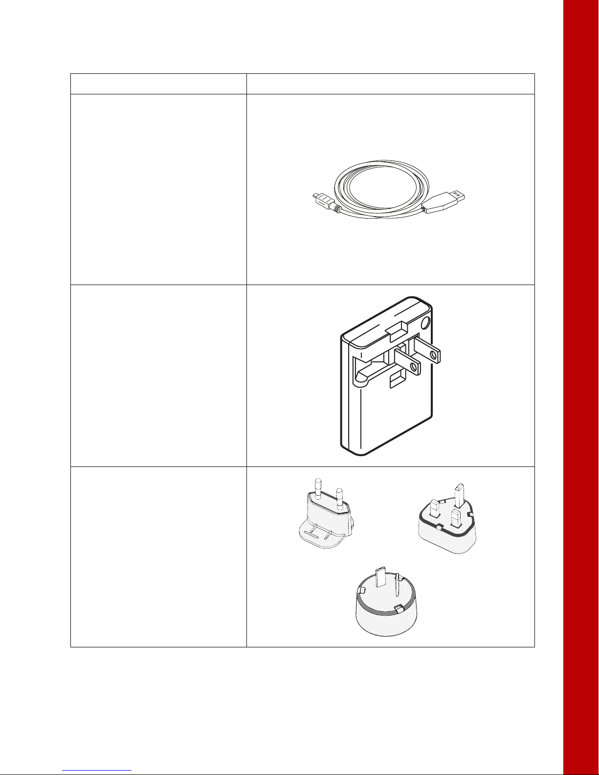
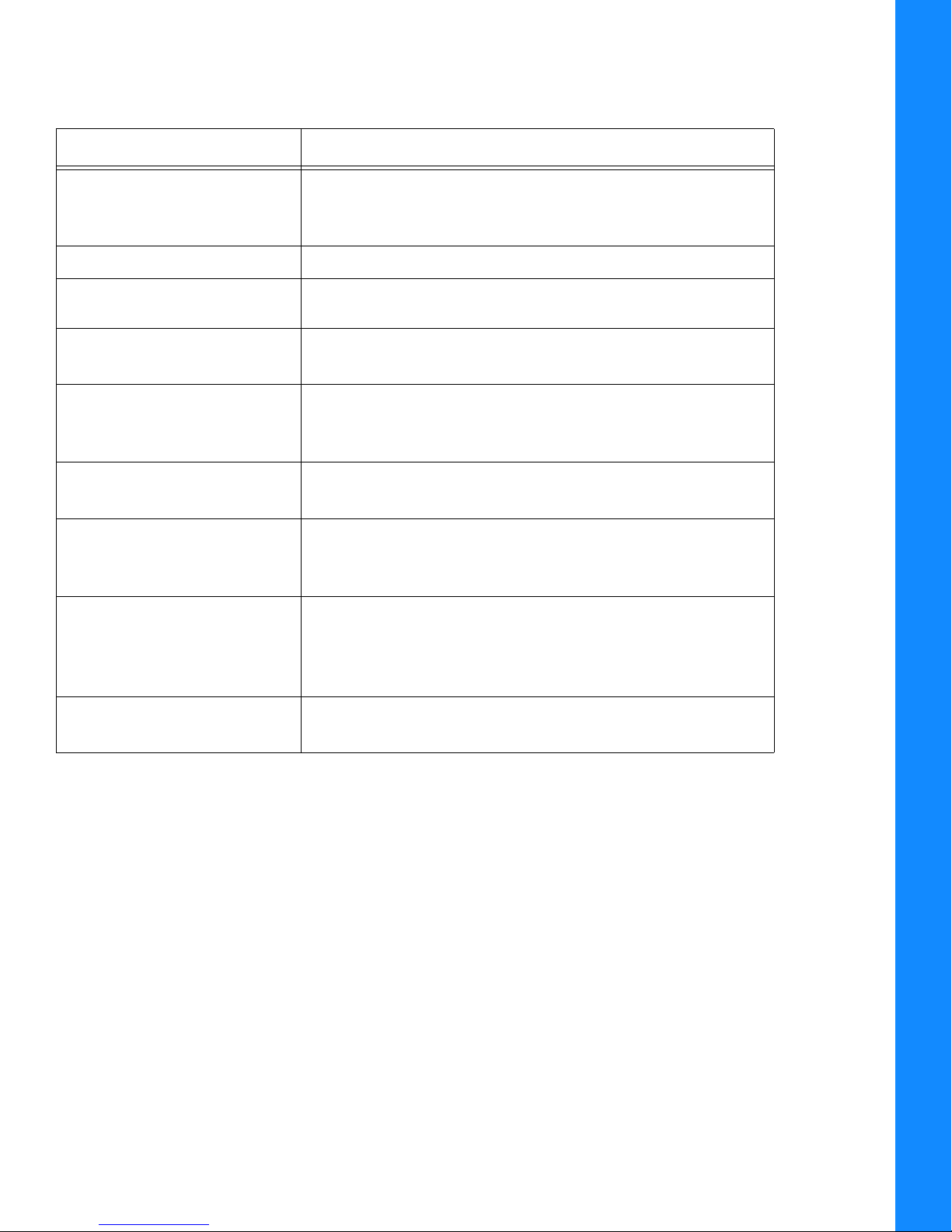
Table 2. Receiver Cable and Adapters
Descriptions Illustration
Micro-AB USB Cable
P/N: 1013602-01
Connects the receiver to an
external device (controller or
computer) for data transfer,
receiver configuration, and to a
power adapter for charging the
internal battery.
Note: Sokkia recommends using
this supplied cable with your
receiver for more stable
communication and charging.
AC/DC Desktop Wall Adapter
P/N: 1005518-01
Getting Acquainted
Charges the receiver when
connected to a grounded outlet and
the power charger cable.
Wall Adapter Folding Clip Kit
P/N: 1005519-01
Power adapters for use in different
countries including the UK,
Australia, and Europe.
Note: Wall adapter folding clip kit
is not required to be added on this
adapter for use in the USA.
Receiver Overview
P/N: 1016293-01
7
Drivers
A 32-bit or 64-bit Windows driver is required. See “Before You Begin Configuring the Receiver” on
page 19.
Memory
The GCX3 is equipped with an internal, non-removable memory card that provides up to 8 GB of data
storage. As data is logged to the receiver’s memory, the REC LED displays the memory capacity status.
See
“Recording and Memory LED (REC)” on page 14 for more information.
To access the raw data files in the receiver’s internal memory, see “Record Data” on page 33.
Internal Battery
The GCX3 receiver was designed with one internal, non-removable battery. When fully charged, the
battery provides all day operation in any job configuration. The battery is easily charged using a
Micro-AB USB cable. See “Internal Battery” on page 16.
Long-Range Bluetooth Technology
Getting Acquainted
The GCX3 receiver integrates Long-Range Bluetooth Technology that enables multiple (up to 3)
cable-free connections to a single GCX3 receiver. This enables Long-Range Bluetooth Technology
operation for base/rover RTK systems. You can also connect the receiver to other Class 1 and
Class 2-enabled Bluetooth devices (such as data collectors and computers) using Bluetooth wireless
technology concurrently with Long-Range Bluetooth connections.
Sokkia’s Long-Range Bluetooth Technology enables communication of RTCM3 differential corrections
between two GCX3 receivers over Bluetooth (up to 300 meters), eliminating the need for additional
external radios for corrections. See
Distance for long-range largely depends upon environmental and field conditions.
“System Setup” on page 30.
Receiver Overview
P/N: 1016293-01
8
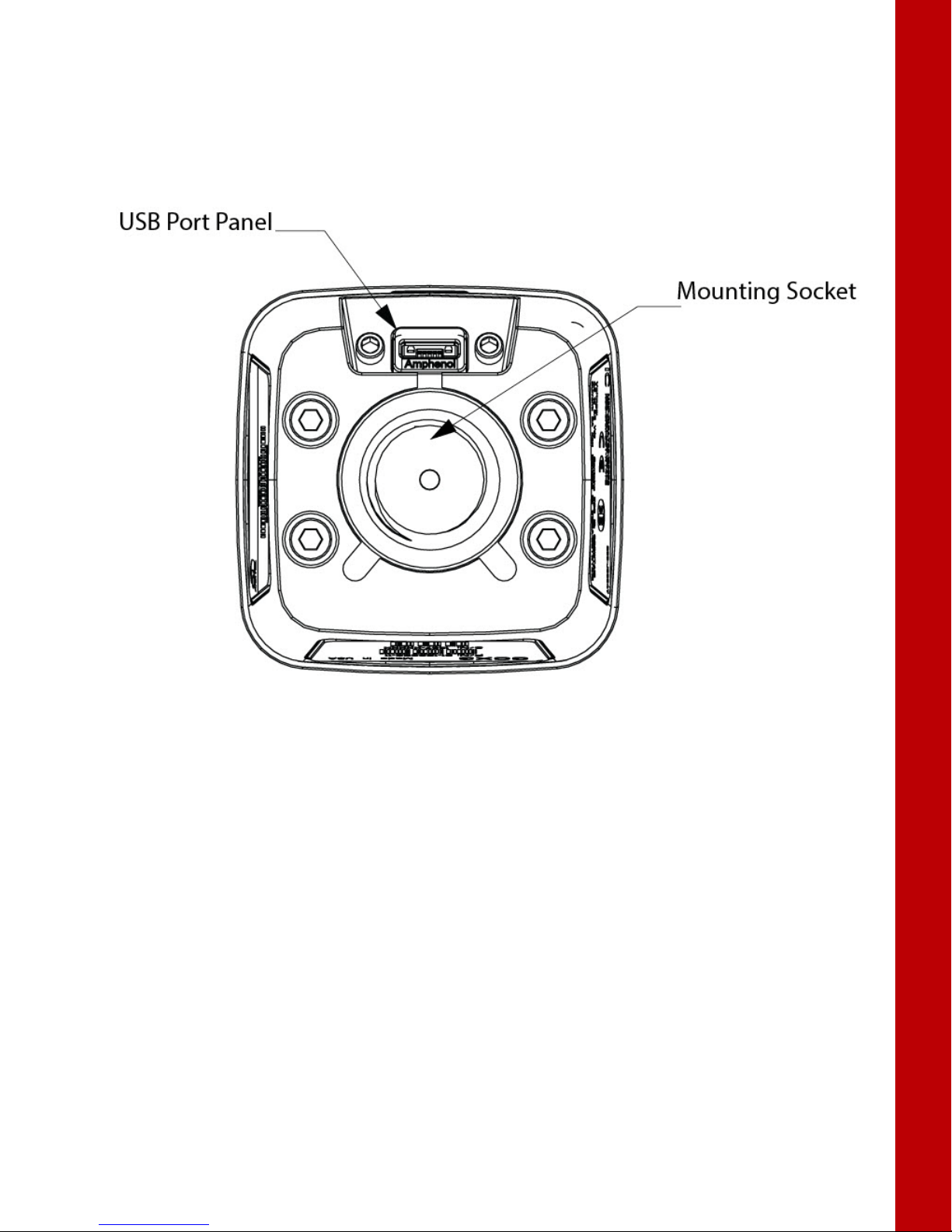
Micro-AB USB Port Panel
The receiver is equipped with a Micro-AB USB port for high-speed data transfer and communication
between the receiver and an external device, for charging the internal battery, and
receiver with an external power supply. See
“Using Internal and External Power Sources” on page 16.
for powering the
Getting Acquainted
Figure 3: Micro-AB USB Port Panel
Receiver Overview
P/N: 1016293-01
9

Display Panel Operations
Power Button
(PWR)
Recording
(REC)
Battery
(BATT)
Bluetooth®
(BT)
Status
(STAT)
The LED display panel provides controls for receiver power and data recording. The LEDs display the
status of satellite tracking, recording/memory capacity, Long-Range Bluetooth Technology connections,
and battery status.
LED Icon Key
Table 3. LED Icon Key
Solid Blinking OFF
Display
Figure 4: LED Display Panel
Display Panel Operations
P/N: 1016293-01
10

Power Button (PWR)
The green power button performs multiple functions. The duration in which the button is pressed and
held determines how the receiver will function. While pressing the button, the LED Display panel
indicates the selected operation for specific LEDs.
Display Panel Operations
Table 4. Power Button Functions
Function
Receiver
Powered ON
Press and Hold
Power Button
2+ seconds Battery LED (BATT) Internal Power Only—solid red, or
solid orange, or solid green. The Battery LED is solid red if
battery capacity < 15%, solid orange if battery capacity is
> 15% but < 50% solid green if the battery capacity >
50%.
See Tab le 8, “Battery LED Blink Patterns—RECEIVER IS
POWERED ON/INTERNAL BATTERY IN USE” for additional
information.
Recording and Memory LED (REC)—blinks red, blinks
yellow, blinks red, and finally solid green. See
additional information.
Satellite Tracking LED (STAT)—blinks red until a
satellite is tracked by the receiver. See
information.
Bluetooth Communication LED (BT)—blinks blue until
a Bluetooth connection is established. Once a BT
connection established, the LED turns solid blue. See
Tab le 7 for additional information.
Battery LED (BATT) External Power Applied to
Receiver—See
RECEIVER IS POWERED ON/EXTERNAL POWER SOURCE
CONNECTED TO RECEIVER” for additional information.
Note: When the battery is at full charge the Battery LED
will display a solid green LED.
Tab le 8, “Battery LED Blink Patterns—
Description
Tab le 6 for
Tab le 5 for additional
Power Button (PWR)
Recording and Memory LED (REC)—blinks red, blinks
yellow, blinks red, and finally solid green. See
additional information.
Satellite Tracking LED (STAT)—blinks red until a
satellite is tracked by the receiver. See
information.
Bluetooth Communication LED (BT)—blinks blue until
a Bluetooth connection is established. Once a BT
connection established, the LED turns solid blue. See
Tab le 7 for additional information.
P/N: 1016293-01
Tab le 5 for additional
Tab le 6 for
11

Table 4. Power Button Functions
Display Panel Operations
Function
Receiver
Powered OFF
Press and Hold
Power Button
Description
3–10 seconds Battery LED Internal Power Only—turns solid red until
Power Button is released. Once the Power Button is
released the Battery LED is OFF. See
Tab le 8, “Battery LED
(BATT) Blink Patterns—RECEIVER IS POWERED
OFF/INTERNAL BATTERY IN USE” for additional
information.
Recording and Memory LED (REC)—OFF,
Status LED—OFF,
Bluetooth LED—OFF
Battery LED (BATT) External Power Source
Connected—if the receiver is powered off and an external
power source is applied, the Battery LED blinks green and
begins charging.
Note: When the battery is at full charge the Battery LED
will display a solid green LED.
See Tab le 8, “Battery LED (BATT) Blink Patterns—
RECEIVER IS POWERED OFF/EXTERNAL POWER SOURCE
CONNECTED TO RECEIVER” for additional information.
Factory Reset
Clear NVRAM
10–15 seconds All LEDs are OFF. Release the Power Button when Status
LED is solid red.
Erase All Files 15–20 seconds All LEDs are OFF. Release the Power Button when
Recording LED is solid red.
Note: This action is irreversible. If unsure about these
actions, continue to hold down the button until all LEDs
return to normal.
Hardware
Shutdown/Reset
More than 35–50
seconds
Shuts down power of all internal components of the
receiver. This function is only recommended when the
receiver goes into Exception mode. This operation does
not affect internal memory or receiver settings.
Open/Close Data
File
Three times in a
row within 2
seconds
Power Button (PWR)
The data file opens in Static mode.
While the file is open, press the power button 2 times in a
row within 1 second to switch back and forth between
Static and Dynamic modes.
To close a data file, press the power button 3 times in a row
within 2 seconds.
Refer to the Recording LED description.
P/N: 1016293-01
12

Receiver Status LEDs
There are four receiver LEDs on the Display Panel. These LEDs display information about:
• GCX3 Satellite Tracking Status (STAT)
• GCX3 Recording and Memory (REC) activity and capacity,
• GCX3 Bluetooth (BT) wireless connectivity status activity,
• GCX3 Battery (BATT) charge level
Satellite Tracking Status (STAT) LED
Tab le 5 below describes the behavior of the Satellite Tracking Status (STAT) LED.
The STAT LED displays number and type of satellites that the receiver is tracking.
Table 5. Satellite Tracking Status (STAT)—LED Blink Patterns
Display Description
GREEN One blink per tracked GPS satellite.
Display Panel Operations
YELLOW One blink per tracked GLONASS satellite.
CYAN One blink per tracked GALILEO satellite.
MAGENTA One blink per tracked BEIDOU satellite.
BLUE One blink per tracked QZSS satellite.
RED One blink per second when there are no tracked satellites.
Receiver Status LEDs
P/N: 1016293-01
13

Recording and Memory LED (REC)
The recording and memory LED (REC) indicates if data is being written to memory and displays how
much memory the receiver has available for recording.
Table 6. Recording and Memory LED (REC) Blink Patterns
Display Function Description
GREEN Greater than 50% File logging is in progress
ORANGE Greater than 10% Each blink indicates that data is
being written to memory.
RED Less than 10%
GREEN Greater than 50% The file is closed. A solid light
indicates no data is being
recorded.
ORANGE Greater than 10%
Display Panel Operations
RED Less than 10%
GREEN and RED Erase all memory Alternating green and red LEDs
indicate all files are being
deleted.
ORANGE and RED Formatting memory Alternating orange and red LEDs
indicate the memory card is being
initialized or formatted.
LED OFF Missing or faulty memory The LED is OFF.
Bluetooth Communication LED (BT)
The Bluetooth (BT) Communication LED displays Bluetooth status activity.
Table 7. Bluetooth LED (BT) Blink Patterns
Display Description
BLUE Bluetooth is ON. Waiting for a connection.
BLUE Single Bluetooth connection is established.
BLUE LongLink connections are established. LED blinks for each
Bluetooth LED
OFF
Receiver Status LEDs
connection every 5 seconds.
Bluetooth is OFF.
P/N: 1016293-01
14

Battery LED (BATT)
The Battery (BATT) LED indicates the remaining charge of the internal battery. When an external
power source is connected to the receiver the LED turns green and begins to blink when the battery
is charging.
Table 8. Battery LED (BATT) Blink Patterns
Display Description
RECEIVER IS POWERED ON/INTERNAL BATTERY IN USE
GREEN The charge is greater than 50%.
ORANGE The charge is greater than 15%.
RED The charge is less than 15%.
RECEIVER IS POWERED ON/EXTERNAL POWER SOURCE CONNECTED
GREEN The battery LED blinks green and the internal battery is greater
than 50% charged. The battery is charging.
Note: When the receiver is powered on—the battery LED will
always blink green when an external power source is
connected—until the battery is fully charged.
Display Panel Operations
ORANGE The battery LED is blinks orange. The internal battery is greater
than 15% charged. The battery is charging.
RED The battery LED is blinks red. The internal battery is less than
15% charged. The battery is charging.
RECEIVER IS POWERED OFF/INTERNAL BATTERY IN USE
Battery LED is
OFF
RECEIVER IS POWERED OFF/EXTERNAL POWER SOURCE CONNECTED
GREEN The battery LED blinks green. The internal battery is charging.
Battery LED is OFF
Note: When the receiver is powered off—the battery LED will
always blink green when an external power source is
connected—until the battery is fully charged.
Receiver Status LEDs
P/N: 1016293-01
15

Managing Power
Turning the Receiver ON/OFF
To turn on the receiver, press and hold the power button until the LEDs briefly flash. When the receiver
is turned ON, the receiver’s channels initialize and begin tracking all visible satellites at any time and
location.
To turn OFF the receiver, press and hold the power button for more than three and less than 10 seconds
(release the power button when the BATT LED blinks solid red). This delay prevents the receiver from
being turned OFF by mistake.
The receiver will draw a small amount of power from the battery when it is turned off. If the
receiver is placed in storage for a long period, such as a few months, the battery may
become fully discharged. You will need to use an external power supply or recharge the
battery before use.
Using Internal and External Power Sources
The receiver is powered by the internal battery or an external power source connected to the Micro-AB
USB port. If an external power source is connected, the receiver draws power from it in preference to
the battery.
Using a standard Micro-AB USB cable, you can connect the receiver to an external power source with
4.5–5.5 VDC to operate the receiver. See
Power input greater than 6 VDC could damage the receiver.
“Specifications” on page 45.
Internal Battery
The receiver first draws power from a connected external power source. When there is no valid external
power source connected or if the source has discharged to a voltage value less than 4.5V, the receiver
will draw its power from one high-capacity internal battery (non-removable)
Depending on use, the hours of operation provided by the internal battery varies. See
Tab le 9.
The GCX3 internal battery will slowly discharge over time, even if the receiver is powered
off. It is highly recommended that the GCX3 be fully charged shortly before each use.
.
Managing Power
P/N: 1016293-01
16

Table 9. Operation Hours
Managing Power
Use Description
MAGNET Relay Base Base sending RTCM 3 differential corrections to
MAGNET Relay Service.
Long-Range
Bluetooth Technology
RTK Base
Long-Range
Bluetooth Technology
RTK or Network RTK
Rover
Static Survey Static setup logging raw GNSS data at 1 Hz. Up to 10
Approximate hours of operation listed are when operated at 20° C.
Base sending RTCM 3 differential corrections to
one Rover.
Rover receiving RTCM 3 differential corrections
over Long-Range Bluetooth Technology or from
a Network site, and corrected through
Bluetooth to a data collector.
Approximate
Hours of Operation
Up to 10
Up to 10
Up to 10
Charging the Battery
When the battery charge is low, the BAT LED changes from solid green, to yellow,
and then red—depending on the amount of remaining charge. See “Battery LED (BATT)” on page 15.
When the receiver is connected to an external power source, the battery charges whether the receiver
is turned ON or OFF.
Procedure for charging the battery
1. Connect the supplied Micro-AB USB cable to the receiver’s Micro-AB USB port.
2. Connect the Micro-AB USB cable to the Micro-AB USB port of the power adapter.
3. Plug the power adapter into an available outlet to fully charge the battery. The time to charge the
battery depends on whether the unit is ON or OFF, and if current is supplied from an external
charger. The BAT LED blinks as the battery charges.
The battery will stop charging when it is at full capacity.
Use a grounded wall outlet or grounded surge protector while charging. The socket should
be located near the equipment and easily accessible.
Using Internal and External Power Sources
P/N: 1016293-01
17

Power Accessories
The Micro-AB USB port of the GCX3 powers and charges the internal battery. The GCX3 is compatible
with standard Micro-AB USB power accessories used with consumer electronic devices. Micro-AB USB
power accessories can be sourced locally as long as Micro-AB USB power standards are met.
Insufficient Power
If the battery becomes fully discharged and an external power supply is not connected, the receiver
will shut down and automatically save the recorded files. To avoid disruptions, check the BAT LED on
the display panel for the battery charge status. See
information.
If the receiver shuts down due to insufficient power, the receiver and all communication ports become
deactivated.
To restore power to your receiver and turn it back on, do one or all of the following:
• Recharge the battery.
• Make sure the Micro-AB USB cable is correctly connected to the receiver’s port.
Managing Power
“Battery LED (BATT)” on page 15 for more
• Connect the receiver to a different power source.
Power supplied to the receiver should match the specifications provided by Sokkia on the
product. Failure to comply with these specifications may damage the receiver.
Insufficient Power
P/N: 1016293-01
18

Configuring the Receiver
The sections in this chapter describe receiver options—how to load a new Optional Authorization File
(OAF), update firmware, and perform a factory reset. Download the Sokkia Receiver Utility (SRU)
software from the Sokkia support website.
Go to http://www.sokkia.com, select your region, and then select the Sokkia Care tab. Select SRU Sokkia Receiver Utility, select Updates for the type of system you have (PC, Mobile).
For information about installing the software, see
SRU Online Help
.
Before You Begin Configuring the Receiver
A USB driver is required to connect the GCX3 to a computer. Determine whether your Windows
operating system is 32-bit or 64-bit, and download the appropriate driver from the Sokkia support
website.
Go to http://www.sokkia.com, select your country or region, select the Sokkia Care tab.
When the GCX3 is connected to a computer for the first time, a driver update will occur on
the computer.
Viewing Receiver Information
In the Sokkia Receiver Utility (SRU), the Receiver Info window displays basic Receiver information,
such as hardware, firmware versions, RAM size, Receiver ID, serial number, and so forth.
Open the Receiver Info Window
1. Connect the receiver to a computer and open the SRU.
2. In the SRU, connect to the receiver.
3. Click DeviceApplication ModeReceiver Managing.
4. Click DeviceConnect.
Configuring the Receiver
P/N: 1016293-01
19

5. In the Connection Parameters window, USB in the connect using the drop down list and click
Connect.
6. In the SRU main window, click the Information icon. The Receiver Info window appears.
Configuring the Receiver
Figure 5: SRU—Receiver Info Window
Loading New Firmware
Receiver board firmware is released as a compressed file that you download and decompress. This
file contains the following files:
• ramimage.ldr – receiver board RAM file
• main.ldp – receiver board Flash file
Uploading Firmware Files to the Receiver
1. Using a Micro-AB USB or Bluetooth connection, connect the receiver to a computer.
Upload firmware to the receiver using a Bluetooth or Micro-AB USB connection. To connect
the receiver to a computer using a Micro-AB USB connection, you will need to install a USB
driver. USB drivers and firmware are available from the Sokkia support website.
Go to http://www.sokkia.com, select your country or region, select the Sokkia Care tab.
2. Click DeviceApplication ModeFirmware Loading.
Loading New Firmware
P/N: 1016293-01
20

3. Click the Firmware Loading icon.
Figure 6: SRU—Firmware Loading
Configuring the Receiver
4. Click DeviceConnect. The Connection Parameters window appears.
Figure 7: Connection Parameters Window
5. Select USB from the Connect Using drop-down list, now click Connect.
Loading New Firmware
P/N: 1016293-01
21

6. The Select Device window appears. Select Receiver in the Device Type field, now click
Next.
Configuring the Receiver
Figure 8: SRU—Select Device
7. The Information window appears, now click Next.
Loading New Firmware
Figure 9: Information Window
P/N: 1016293-01
22

8. The Select Files screen appears, now click the Browse icon next to the Image field, and
select the receiver board’s main file.Click Next to upload the firmware.
Figure 10: Selecting the Receiver Board’s Main File
Configuring the Receiver
9. During the firmware update the following message may appear.
Figure 11: SRU Firmware Update Confirmation
10. After the firmware has been successfully updated, the receiver automatically performs the reset
receiver procedure. The receiver is then disconnected from the Sokkia Receiver Utility (SRU). To
continue work on the receiver click OK.
Loading New Firmware
P/N: 1016293-01
23

Optional Authorization Files (OAFs)
Sokkia issues an Optional Authorization File (OAF) to enable the specific options purchased. Sokkia’s
OAF system enables you to customize and configure the receiver according to your particular needs.
This allows you to purchase only the options you require.
The GCX3 receiver ships with standard GPS/GLONASS L1, 1-Hz Static OAF option. Upgrade OAFs are
available for purchase. Contact your local dealer for more information about available receiver options
for the GCX3.
The GCX3 receiver is capable of Dual Frequency Static, Long Range, Network RTK, and
MAGNET
Contact your Sokkia dealer or a representative for a complete listing of available options and pricing
information.
Relay operation.
Checking the Receiver’s OAFs
Viewing Receiver Options Using the Sokkia Receiver Utility
Configuring the Receiver
(SRU)
1. Connect the receiver to a computer and open SRU. See
2. In SRU, connect to the receiver.
3. From the main window, click the Options icon.
4. The Receiver Options window appears. View the current authorization options.
SRU Online Help
for more information.
Optional Authorization Files (OAFs)
Figure 12: Receiver Options
P/N: 1016293-01
24

Loading an OAF
Sokkia dealers provide customers with OAF files. For OAF related questions, e-mail Sokkia at
options@sokkia.com. Include the Receiver’s ID and serial number. See
on page 19.
Loading a New OAF
1. Check the receiver’s OAF. See “Checking the Receiver’s OAFs” on page 24.
2. Right-click on the Receiver Options window, and select Upload OAF.
“Viewing Receiver Information”
Configuring the Receiver
Figure 13: Select Upload OAF
3. Navigate to the location of the new OAF.
Optional Authorization Files (OAFs)
P/N: 1016293-01
25

4. Select the appropriate file, and click Open.
Figure 14: Loading an OAF
Configuring the Receiver
The SRU initially checks to see if the selected file is compatible with the current connected
receiver. If a file is chosen that is not intended for this receiver, the Upload OAF window
displays an error icon next to the Receiver ID and disables the Upload the File to the
Receiver button (
Figure 15).
5. The Upload OAF window appears. Click Upload the File to the Receiver to start loading the
file.
Figure 15: Upload the OAF to the Receiver
Optional Authorization Files (OAFs)
P/N: 1016293-01
26

6. At the SRU Window, click Yes to reset the receiver.
Figure 16: SRU Window—Reset Receiver
7. When the receiver resets, the Connection Parameters window opens. Click Connect.
Configuring the Receiver
Figure 17: Connection Parameters Window—Connect to the Receiver
8. The Sokkia Receiver Utility main window appears. Click Options.
Figure 18: Click Options
Optional Authorization Files (OAFs)
P/N: 1016293-01
27

9. The Receiver Options window displays. Ensure the following are correct:
• If a leased OAF was uploaded—the expiration dated is still valid
• If a permanent OAF was uploaded the correct options are loaded.
Configuring the Receiver
Figure 19: Receiver Options Window
10. To view additional OAF details, right-click in the Receiver Options window and select View
Details.
Figure 20: Receiver Options Window—Additional OAF Details
Optional Authorization Files (OAFs)
P/N: 1016293-01
28

Resetting the Receiving (Clearing) NVRAM
The receiver’s Non-Volatile Random Access Memory (NVRAM) holds data required for satellite
tracking, such as ephemeris data and receiver position. The NVRAM also keeps the current receiver’s
settings, elevation masks, recording interval, and information about the receiver’s internal file system.
Clearing the receiver’s NVRAM resets the receiver and restores the receiver to factory default settings.
Although performing a factory reset of the receiver is not recommended as a common practice, there
are times when it can eliminate communication or tracking problems.
After performing a reset, the receiver requires about 15 minutes to collect new ephemeris and
almanacs.
Ephemeris—A table giving the coordinates of a celestial body at a number of specific times
during a specific period.
Resetting the receiver will not delete any files already recorded in the receiver’s memory, and the
NVRAM keeps information about the receiver file system.
Clearing NVRAM Using Sokkia Receiving Utility (SRU)
Configuring the Receiver
1. Connect the receiver to a computer, and open SRU. See
2. In SRU, connect to the receiver.
3. From the main window, click the Tools icon .
4. The Tools window appears. Click Factory Reset, and then click Yes to continue.
SRU Online Help
for more information.
Resetting the Receiving (Clearing) NVRAM
Figure 21: Tools Dialog Box
P/N: 1016293-01
29

System Setup
The GCX3 receiver’s advanced design eliminates the need for cables during operation, enabling for a
simplified setup with less parts to keep track of.
You can set up the GCX3 receiver in static or RTK configurations in the field and transmit RTK corrections
from the Base to the Rover receiver using Long-Range Bluetooth
connect to a controller running Sokkia Receiver Utility (SRU) and MAGNET
instrument and to collect and manage data.
Setting Up the Base Receiver
1. Mount the receiver on a tripod with a Tribrach Adapter.
Technology. You can use Bluetooth to
TM
Field to configure the
2. Position the base system over a known point.
3. Level the tripod and measure the height of the receiver from the ground using the tape measure.
“Measuring Antenna Height” on page 32.
See
System Setup
Figure 22: Base Receiver
P/N: 1016293-01
30

4. Press the power button to turn the receiver ON. The integrated wireless device in the receiver
turns on when the receiver is powered.
5. Connect the receiver to the Bluetooth-enabled data collector, running Sokkia Field software, to
configure and start the base GCX3 receiver.
6. View the LED display panel for the receiver’s current status. See “Display Panel Operations” on
page 10.
Setting Up the Rover Receiver
1. Mount the receiver on the Range Pole.
System Setup
2. Attach a Sokkia controller to the pole using a mounting bracket.
3. If you are not using a fixed height Range Pole, measure the height of the receiver from the
ground. See
4. Press the power button to turn the receiver ON. The integrated wireless device in the receiver
turns on when the receiver is powered.
5. Connect the receiver to the Bluetooth-enabled data collector that is running Sokkia Field
software, to configure the GCX3 as a rover receiver.
6. View the LED display panel for the receiver’s current status. See “Display Panel Operations” on
page 10.
Setting Up the Rover Receiver
“Measuring Antenna Height” on page 32.
Figure 23: RTK Rover
P/N: 1016293-01
31

Measuring Antenna Height
The receiver calculates the coordinates of the antenna’s phase center. To determine the coordinates
of the station marker, specify the following:
• measured height (H) of the bottom of the receiver above the station marker (see Figure 24)
• model of the receiver (GCX3) used
Any necessary antenna phase center adjustments, based on the antenna model, is automatically
applied. This adjustment, when combined with accurately measured height and measurement
methods, enables correctly computed reference marker coordinates.
Obtaining Accurate Antenna Height
1. Measure the height of the bottom of the receiver or Antenna Reference Point (ARP) above the
control point or marker.
Topcon software only requires input of measured height (H) to compute coordinates of the
Antenna phase center of the receiver. For precise antenna height, it is recommended that
you use the vertical measurement method shown in
System Setup
Figure 24.
Figure 24: Obtaining Accurate Antenna Height
Measuring Antenna Height
P/N: 1016293-01
32

Collecting Data
Collecting Data
This chapter provides general information about recording data, downloading it, and removing files to
free up internal receiver memory.
Setting Recording Parameters
The Sokkia Receiver Utility (SRU) software enables you to set logging parameters, such as logging rate
and types of messages—in which to record data. See
The GCX3 is compatible with any Sokkia field software used for configuration and recording raw data.
Log Rates
The receiver provides up to 8 GB of file space on the internal (non-removable) memory card. The
amount of memory used to log data depends on the logging rate. See
information.
SRU Online Help
for more information.
SRU Online Help
for more
Record Data
Log raw GNSS data to the receiver’s internal memory and use the Sokkia Receiver Utility (SRU) or
MAGNET Office software to download the files to a computer.
Start/Stop Recording Using LED Display Panel or SRU
1. Press the power button to turn the receiver ON.
2. Wait for the Status (STAT) LED to indicate that the satellites are being tracked.
The Status (STAT) LED blinks green for GPS satellites and amber for GLONASS satellites. A
short red blink indicates the receiver has not resolved its position location. Five or more
satellites provide optimal positioning.
3. Press the Power (PWR) button three times within two seconds to begin recording. To begin
recording data, in the Sokkia Receiver Utility select, File Explorer
4. Ensure that the Recording and Memory (REC) LED blinks green—this is an indication that a file has
opened and that data collection is occurring. The (REC) LED blinks when raw data is being logged
to internal memory.
LogsStart.
5. Recording and Memory (REC) LED is blinking green. This indicates that a file has opened and data
collection has started. The REC LED blinks each time data is saved to the internal memory.
6. When finished recording, press the Power button three times within two seconds. Ensure that the
REC LED is dark. To end data recording, in SRU select File Explorer
Collecting Data
P/N: 1016293-01
LogsStop.
33

7. To turn the receiver OFF, press and hold the power button for 3–10 seconds until all LEDs power
OFF and the BAT LED is solid red.
You can also log data using MAGNET Field software.
File Management
Raw data is recorded as time-tagged measurements in a single raw data file. Each file is recorded to
the receiver’s internal memory, automatically given a name, and a *.tps file extension. You can then
transfer a file of collected data to a computer with file managing software, such as the Sokkia Receiver
Utility (SRU). This program enables you to use an automatic naming feature, enter file names, and
delete files as necessary.
See
SRU Online Help
Downloading and Deleting Files
for more information.
Collecting Data
After completing a survey, download data files to a computer or a controller for storage, postprocessing, or backup. The receiver’s internal memory holds a finite amount of files, so you will want
to delete files to restore memory capacity.
When the internal memory is full, the receiver stops logging data, and the REC LED turns dark/off,
indicating an error condition. Existing data is not overwritten, unless AFRM mode is enabled.
There are two options for deleting raw data files from the receiver:
• Delete all of the files using the LED display panel.
Pressing and holding the Power button for 15–20 seconds erases all of the files in the
receiver’s internal memory.
• Use a Micro-AB USB or Bluetooth connection to download the files to a computer. In SRU, you
can select the files you want to delete from the receiver. See
information.
Once a connection is established, you can download all or some files to a computer or controller and
use the File Explorer feature in Sokkia Receiver Utility (SRU) to manage the raw data files.
SRU Online Help
for more
For more information about using SRU to download or delete files, see
Collecting Data
P/N: 1016293-01
SRU Online Help
.
34

Troubleshooting
This chapter will help you diagnose and solve some common problems that may occur with the GCX3
receiver.
Do not attempt to repair equipment yourself. Doing so will void the warranty and may
damage the hardware.
Check this First
Before contacting your local dealer or Sokkia Technical Support, check the following:
• Check all external receiver connections carefully to ensure that the connectors are correctly
seated and secure.
• Check for worn or defective cables.
• Check that the receiver’s internal battery is fully charged.
• Check the power source for incorrectly connected cables, and ensure that the power source is
valid. See
“General GCX3 Specifications” on page 45 for external power requirements.
• Verify that he most current software version is downloaded on to the computer and the most
current firmware is loaded onto the receiver. For the latest updates, go to:
http://www.sokkia.com, select your region, and then select the Sokkia Care tab. Select SRU -
Sokkia Receiver Utility, select Updates for the type of system you have (PC, Mobile).
• Check Sokkia Technical Support.
Go to http://www.sokkia.com/, select your region, and then select the Contact Us for the latest
updates.
Now, do the following:
• Power cycle OFF/ON the receiver by pressing the Power button or by using SRU
(ToolsReset receiver). See “Power Button Functions” on page 11.
• Restore default settings by pressing holding the Power button for 10–15 seconds or using SRU
(ToolsFactory Reset). This restores the receiver’s parameters to the factory default settings
and erases the almanac and ephemeris files. This action does not delete data files from the
receiver memory. See
“Power Button Functions” on page 11.
• Erase all files by pressing and holding the Power button for 15–20 seconds or by using
File ExplorerDelete All Files in SRU. This will delete all files stored in the receiver’s
non-removable memory (NVRAM) card. See “Power Button Functions” on page 11.
If the problem persists, see the following sections for other solutions.
Troubl esho oti ng
P/N: 1016293-01
35

Powering Problems
The following table describes some commonly encountered power problems.
Receiver Does Not Power Up
Cause Solution
The battery may be discharged. • Charge the battery overnight.
If an external power source is being
used, the cable may be disconnected
or damaged.
The receiver may have a defective
charger or defective battery.
Additional Receiver Problems
Troubleshooting
See “Charging the Battery” on page 17
• Ensure the cable is securely connected and
undamaged.
• If, after changing the battery or connecting an
external power source, the receiver still does
not power up, contact your local dealer or
Sokkia Technical Support for advice.
The following table describes some commonly encountered receiver problems. Such as:
• No Connection to Computer or External Controller
• Cable Specific Problems
Cause Solution
The cable is not properly plugged in. • Unplug the cable, then securely and properly
reconnect it to the receiver.
The cable is damaged. • Use an undamaged cable. If necessary,
contact a dealer to replace the cable.
The USB driver is not installed. • If a Micro-AB USB cable connector is being
used, ensure that the Micro-AB USB driver is
correctly installed on the computer.
The driver may be downloaded from the
Sokkia website: http://sokkiasupport.com.
The cable is damaged. • Use an undamaged cable. If necessary,
contact a dealer to replace the cable.
Powering Problems
P/N: 1016293-01
36

Generic Problems
The following table describes some commonly encountered Generic Problems.
Cause Solution
Troubleshooting
The receiver port used for connection
is not in Command mode.
The receiver goes into Exception
mode and/or is non-responsive or
frozen and can not be recovered by
reloading firmware.
• Use Bluetooth to connect the receiver to a
computer and then open SRU
SRU Online Help
See
information.
• Click Receiver SettingsPorts.
• Change the Input mode for the port used for
connection to cmd.
• Hardware Shutdown/Reset by pressing power
button for more than 35–50 seconds.
This shuts down power to all internal
components of the receiver. This operation
does not affect internal memory or receiver
settings.
for additional
No Long Term Lock on Satellites
The following table describes some commonly encountered satellite problems.
Cause Solution
The corresponding receiver options
may be disabled or expired (L1/L2,
GPS/GLONASS must be on to track
satellites).
• Order a new OAF with the desired options
activated to enable or extend validity of the
corresponding receiver options. Contact a
dealer or visit the Sokkia website for details.
• For a detailed description of options, see
Online Help
for additional information.
SRU
Powering Problems
P/N: 1016293-01
37

Too Few Satellites Tracked
The following table describes some commonly encountered satellite tracking problems.
Cause Solution
Troubleshooting
The survey is conducted near
obstructions (tree canopy, tall
buildings).
• Ensure the Multipath Reduction boxes have
been enabled.
a. Connect the receiver to a computer
and open the SRU
See
SRU Online Help
information.
b. In the SRU, connect to the receiver.
c. On the SRU main window, choose
Receiver
SettingsTrackingAdv tab.
Ensure that the C/A code multipath
reduction check box is selected.
• Move to an area free of obstructions, if
applicable.
for additional
Powering Problems
P/N: 1016293-01
38

No Code Differential and/or Real Time Kinematic (RTK)
Solutions Obtained
Cause Solution
Incorrect Base coordinates entered. • Specify the correct coordinates for the Base
station using SRU or other suitable field data
collection software.
Obstruction between the Long-Range
Bluetooth Technology connection
• Clear all possible obstructions or relocate the
Base so there is a “line-of-sight” path to the
Rover.
Troubleshooting
The corresponding receiver options
may be disabled or expired.
There are not enough common
satellites. In order to obtain a fixed
solution, the Base and Rover should
track at least five common satellites.
A discrepancy exists between the
differential standards used at the
Base and Rover receivers.
Poor satellite geometry (PDOP/GDOP
values are too high)
The elevation mask is above 15
degrees.
• Order a new OAF with the required options
activated to enable or extend validity of the
corresponding receiver options.
•See
• Check the elevation masks of the Rover and
• Verify there is a clear view of the sky to allow
• Ensure the Base and Rover receivers use the
• Conduct the survey where satellite visibility is
• Ensure the elevation mask is less than 15
• Lower the elevation mask. To do this, on the
SRU Online Help
information.
Base receivers; they should be the same. To
do this, on the SRU main window, choose
Receiver SettingsTrackingObs.
sufficient satellite tracking.
same corrections input/output format:
a. Connect the receiver to a computer
and open SRU
SRU Online Help
See
information.
b. In SRU, connect to the receiver.
c. On the SRU main window, choose
Receiver SettingsPorts.
d. Double-click on the port to be
configured and Ensure the input
mode of the Rover matches the
format of the Base output mode (i.e.
RTCM3).
better (low PDOP value).
degrees.
SRU main window, choose Receiver
SettingsTrackingObs.
for additional
for additional
There may be a source of radio
interference that disrupts radio
communications.
Powering Problems
• Verify that there is a clear view of the sky to
allow sufficient satellite tracking.
• Change the RF channel (if possible).
• Removing the source of the jamming signal or
relocate the radio antennas (if possible).
P/N: 1016293-01
39

Receiver Does Not Log Data
Cause Solution
Troubleshooting
The receiver’s memory is disabled or
expired.
• The receiver’s memory is disabled or expired.
• Ensure that the memory option is enabled. See
SRU Online Help
• The receiver’s internal memory card does not
have free space.
• Download and/or delete data files to free up
space for new files. See “Downloading and
Deleting Files” on page 34.
• Use the SRU to re-initialize the file system, this
may resolve SD Card memory issues.
for additional information.
Powering Problems
P/N: 1016293-01
40

Bluetooth Problems
The following table describes some commonly encountered error messages and other Bluetooth
problems.
SRU Error Message—Can’t Find Receiver
Cause Solution
The receiver is turned OFF. • Ensure the receiver has power and is turned
Bluetooth is not turned on; the
Bluetooth (BT) LED is OFF.
There is interference • Move the receiver, controller, or computer to
The receiver is too far away. • Move the devices closer together.
The receiver is already connected via
Bluetooth to another device.
The receiver port used for connection
is not in Command mode.
on.
• Reset the receiver to the factory default
settings by pressing the Power button for 10 to
15 seconds.
an unobstructed location.
• Disconnect the receiver from the other
controller or computer.
• Connect the receiver to a computer and open
SRU
SRU Online Help
See
information.
for additional
Troubleshooting
• Click ConfigurationReceiverPorts.
• Change the Input Mode for the Bluetooth or
Micro-AB USB port used for connection to cmd
Long-Range Bluetooth Technology connections will not interfere with Bluetooth connections
to computers or controllers.
Use the SRU to double verify that the settings for the connection port are correct.
Bluetooth Problems
P/N: 1016293-01
41

No Available Devices Discovered
Cause Solution
The receiver is not receiving power. • Check that the receiver is getting power and is
turned ON.
• Check that the power cable is correctly
attached to the port.
• Unplug the cable, then securely and properly
reconnect it to the receiver.
• If the power cable is damaged, contact a
Dealer to purchase a new cable.
Receiver Bluetooth Icon Visible—Cannot Establish
Connection
Cause Solution
Troubleshooting
Device security settings probably
differ
Bluetooth module settings may have
changed.
• Ensure that the Bluetooth enabled devices use
the same security settings.
• If the settings are changed for the Bluetooth
module, remove it from the list of discovered
Bluetooth devices using the Bluetooth
manager program (supplied with the device
used to manage the receiver).
• Repeat the search.
Bluetooth Problems
P/N: 1016293-01
42

Long-Range Connection Problems
The following tables (2) describe commonly encountered Base Receiver and Bluetooth connection
problems.
Long-Range Connections—Cannot Discover the Base
Receiver
Cause Solution
The Base is out of range. Ensure the Base receiver is within 300 meters of
the Rover. Distance for Long-Range largely
depends upon environmental and field
conditions.
The Base is not responding. • Ensure that the Base is turned ON.
• Ensure Bluetooth is turned ON for the Base
and Rover
Note: The Bluetooth LEDs are blue ON both
receivers.
• Ensure that there are no obstructions or
interference.
• Ensure that the Bluetooth pin code is correctly
entered.
Troubleshooting
Cannot Establish a Bluetooth Connection
Cause Solution
A Long-Range Bluetooth connection is
not available at the Base. (for
example, three connections are
already established.)
• Ensure that there are no obstructions or
interference between the Base and the Rover.
Long-Range Connection Problems
P/N: 1016293-01
43

Sokkia Receiver Utility (SRU) Problems
The following table describes some commonly encountered Sokkia Receiver Utility problems.
SRU Cannot Connect to Receiver
Cause Solution
The receiver is turned OFF. • Ensure the receiver has power and is turned
ON.
If using a Micro-AB USB cable, the
cable’s connectors are improperly
attached.
If using a Micro-AB USB cable, the
cable is damaged.
• Unplug the cable, then securely and properly
reconnect it to the receiver.
• Use an undamaged cable.
• Contact a dealer to purchase a new cable.
Troubleshooting
If using Bluetooth wireless
technology, the incorrect port is
selected.
• Use a computer or receiver that has Bluetooth
wireless technology enabled/installed.
• Ensure the computer and receiver use the
correct ports for communication. For the GCX3
receiver, this is Bluetooth or Micro-AB USB.
Cleaning and Storing the Receiver
• Use a clean cloth moistened with neutral detergent or water.
• Never use an abrasive cleaner, ether, thinner benzene, or other solvents.
• Always ensure the receiver is completely dry before storing it. Dry any moisture with a soft,
clean cloth.
Getting Customer Support
If the troubleshooting hints and tips in this operator’s manual fail to remedy the problem, contact a
Sokkia Customer Representative. For contact information, see
“Getting Technical Support” on page 4.
Sokkia Receiver Utility (SRU) Problems
P/N: 1016293-01
44

Specifications
The GCX3 is a GNSS receiver featuring 226 channels and Long-Range Bluetooth Technology for small
job site operations and cable-free network solutions.
General Details
Tab le 10 is a list of the general specifications for the GCX3.
Physical
Enclosure Aluminum alloy with Lexan cap
Color Sokkia Gray and Blue (base)
Table 10. General GCX3 Specifications
Dimensions
(mm)
Weight (g)
including
battery
Status
display/panel
Micro-AB
USB/Power
Bluetooth
antenna
Tracking
Number of
Channels
Tracked
Signals
47 (w) x 47 (d) x 197.0 (h) mm
Up to 440 g, depending on the configuration
MINTER (Minimum Interface), 4 LEDs + 1 power button)
Micro-AB USB (for communications and power)
Fully integrated, high-sensitivity
226 channels with optimized satellite tracking technology
GPS: L1 C/A, L2P, L2C code and carrier
GLONASS: L1 C/A, L1P, L2 C/A, L2P code and carrier
SBAS: L1 C/A, WAAS/MSAS/EGNOS/GAGAN
QZSS: L1 C/A, L1-SAIF, L1C, L2C
Galileo E1
BeiDou B1, B2
Note: Support for L1C signal for QZSS is incorporated and will be available
through firmware upgrade.
Multipath
reduction
PLL/DLL
setting
Smoothing
interval
Data Output
Specifications
Yes, code and carrier
Adjustable bandwidth and order
Pseudo-range smoothing: Adjustable
P/N: 1016293-01
45

Table 10. General GCX3 Specifications
Specifications
RTK
TPS, RTCM SC104 v 2.x, 3.x (including MSM); CMR/CMR+
corrections
ASCII output NMEA 0183 version 2.x and 3.0
RTK position
10 Hz
data rate
Measurement
10 Hz
data rate
Real time data
output
TPS; RTCM SC104 v 2.x and 3.x; GCX3
Note: CMR/CMR+ is a third-party proprietary format. Use of this
format is not recommended and performance is not guaranteed. Use of
industry standard RTCM 3.x is always recommended for optimal
performance.
Data and Memory
Removable
None
media
Internal
Internal up to 8 GB pre-installed
memory
Message
10 Hz; up to 3,000 files
storage rate
(maximum)
Environment
Operating
temperature
Battery Charging: -0° C to +45° C
Battery Operation: -20° C to +63° C (with internal batteries)
Cable Operation: -40° C to +63° C (with external power)
Storage
-40°C to +85°C
temperature
Humidity 100%, condensing
Waterproof
IPX7 (1 meter submersion)
rating
Dust rating IP6X (Fully dust proof)
Random
vibration
MIL-STD 810G, Method 514.6, Broad band noise (random vibration), along
each of 3 axes, Category 4, Table 514.6C-IV
Shock MIL-STD 810G Method 516.6. Table 516.6-I Alternate Test Method of
Classical Pulse; 40 grams, 11 milliseconds duration.
Toppl e 2.0 meter pole drop—1.0 meter handling drop
Technology
Long-Range Bluetooth Technology
Optimized Satellite Tracking Technology
Precision Orbital Satellite Technology (POST) integrated antenna
Power
General Details
P/N: 1016293-01
46

Table 10. General GCX3 Specifications
Specifications
Internal
3.6 V, 5800 mAh
Battery
(non-
removable)
Battery
<5 hours if unit is OFF and using external 2A power source.
charging time
Note: Charging time depends on external charger and cable used.
Battery
charging
method
Connect to a Micro-AB USB power adapter to charge the internal battery.
Available run charge when connected to an external power adapter.
Charging of internal battery when power input is greater than 4.5 V.
Operating time Up to 10 hours
General Details
P/N: 1016293-01
47

Table 10. General GCX3 Specifications
Specifications
External power
input
4.5–5.5 VDC USB standard, normal ambient conditions
Note: 4.5–5.5 VDC is the operating range of the external power source
when the receiver is on. To turn the receiver on, the power input must be
between 4.5 and 5.5 VDC. To charge the internal battery, the external
power input must be greater than 4.5 VDC.
Power
consumption
External power
supply adapter
1.5 W (RTK Rover with Long-Range Bluetooth Technology, using the
internal battery at 20° C)
Input: 100–240 VAC, 50–60 Hz, 0.8 A
Output: +5 VDC/2 A
rating
Communication
USB 1 port; Micro-AB USB (client)
Long-Range
Bluetooth
Technology
300 meter range with up to 3 simultaneous rovers.
Typical long-range distance with clear line of sight. Distance for long-range
largely depends upon environmental and field conditions.
Bluetooth v2.1 + EDR
Survey Accuracy
Static, faststatic (postprocessed)
Kinematic,
RTK
L1+L2:
H: 3.0 mm + 0.4 ppm
V: 5.0 mm + 0.6 ppm
L1+L2:
H: 10 mm + 0.8 ppm
V: 15 mm + 1.0 ppm
DGPS H: 0.4 meters, V: 0.6 meters
SBAS H: 1.0 meters, V: 1.5 meters
Maximum data
10 Hz
rate
Cold start
<60 seconds
Warm start
Reacquisition
RTK Time-to-
<35 seconds
<1 second
2–8 seconds
First-Fix
(TTFF)
General Details
P/N: 1016293-01
48

Safety Warnings
General Warnings
To comply with RF exposure requirements, maintain at least 25 cm between the user and
the receiver when operating Long-Range Bluetooth Technology.
Sokkia receivers are designed for survey and survey related uses (that is, surveying coordinates,
distances, angles, depths, and recording such measurements). This product should never be
used:
• Without the user thoroughly understanding this manual.
• After disabling safety systems or altering the product.
• With unauthorized accessories.
• Without proper safeguards at the survey site.
• Contrary to applicable laws, rules, and regulations.
Sokkia receivers should never be used in dangerous environments. Use in rain or snow for a
limited period is permitted.
Battery Warnings
Tampering with the battery by end users or non-factory authorized technicians will void the
battery’s warranty.
• Do not charge in conditions different than specified.
• Do not use other than the specified battery charger.
• Do not short circuit.
• Do not crush or modify.
Receiver Warnings
Tampering with the receiver by the end users or non-factory authorized technicians will void
the receiver’s warranty:
• Do not attempt to open the receiver and modify any of its internal components.
• Do not charge in conditions different than specified.
• Do not short circuit.
Usage Warnings
If this product has been dropped, altered, transported or shipped without proper packaging,
or otherwise treated without care, erroneous measurements may occur.
The owner should periodically test this product to ensure it provides accurate measurements.
Inform Sokkia immediately if this product does not function properly.
Safety Warnings
P/N: 1016293-01
49

Regulatory
The following sections provide information on this product’s compliance with government regulations
for use.
FCC Compliance
This equipment complies with FCC radiation exposure limits set forth for uncontrolled equipment and
meets the FCC radio frequency (RF) Exposure Guidelines in Supplement C to OET65. This equipment
has very low levels of RF energy that it deemed to comply without maximum permissive exposure
evaluation (MPE). But it is desirable that it should be installed and operated with at least 20 cm and
more between the radiator and person’s body (excluding extremities: hands, wrists, feet and ankles).
This equipment has been tested and found to comply with the limits for a Class B digital device pursuant
to part 15 of the FCC rules. These limits are designed to provide reasonable protection against harmful
interference when the equipment is operated in a commercial environment. This equipment generates,
uses, and can radiate radio frequency energy and, if not installed and used in accordance with the
instruction manual, may cause harmful interference to radio communications. Operation of this
equipment in a residential area is likely to cause harmful interference in which case the user will be
required to correct the interference at his own expense.
If this equipment does cause interference to radio or television equipment reception, which can be
determined by turning the equipment off and on, the user is encouraged to try to correct the
interference by one or more of the following measures:
• Reorient or relocate the receiving antenna.
• Move the equipment away from the receiver.
• Plug the equipment into an outlet on a circuit different from that to which the receiver is powered.
• Consult the dealer or an experienced radio/television technician for additional suggestions.
Any changes or modifications to the equipment not expressly approved by the party
responsible for compliance could void your authority to operate such equipment.
Industry Canada Compliance
This class B digital apparatus complies with Canadian CAN ICES-3 (B)/NMB-3(B).
Cet appareil numérique de la classe B est conforme à la norme NMB-003 du Canada.
This device complies with Industry Canada licence-exempt RSS standard(s). Operation is subject to the
following two conditions: (1) this device may not cause interference, and (2) this device must accept
any interference, including interference that may cause undesired operation of the device.
Le présent appareil est conforme aux CNR d’Industrie Canada applicables aux appareils radio exempts
de licence. L’exploitation est autorisée aux deux conditions suivantes: (1) l’appareil ne doit pas produire
de brouillage, et (2) l’utilisateur de l’appareil doit accepter tout brouilage radioélectrique subi, même si
le brouillage est susceptible d’en compromettre le fonctionnement.
Regulatory
P/N: 1016293-01
50

Community of Europe Compliance
The product described in this manual is in compliance with the R&TTE and EMC directives from the
European Community.
European Community Declaration of Conformity with
R&TTE Directive 1999/5/EC
The following standards were applied: (R&TTE Directive 1999/5/EEC)
• EN 301 489-1 V1.9.2
• EN 301 489-3 V1.6.1
• EN 301 489-17 V2.2.1
• EN 300 328 V1.8.1
• EN 300 440-2 V1.4.1
• EN 55022:210/AC:2011
• EN 55024:2010
Regulatory
• EN 60950-1:2006+A2:2013
The following CE mark is affixed to the device:
This is a Class A product. In a domestic environment this product may cause radio
interference in which case the user may be required to take adequate measures.
Community of Europe Compliance
P/N: 1016293-01
51

Declaration of Conformity (R&TTE Directive 1999/5/EC)
Regulatory
esky [Czech]
Dansk [Danish] Undertegnede
Deutsch
[German]
Eesti [Estonian] Käesolevaga kinnitab
English Hereby,
Español [Spanish] Por medio de la presente
[Greek]
(Sokkia)
požadavky a dalšími píslušnými ustanoveními smrnice 1999/5/ES.
overholder de væsentlige krav og øvrige relevante krav i direktiv
1999/5/EF.
Hiermit erklärt
mit den grundlegenden Anforderungen und den übrigen einschlägigen
Bestimmungen der Richtlinie 1999/5/EG befindet.
tímto prohlašuje, že tento
(Sokkia)
(Sokkia)
erklærer herved, at følgende udstyr
dass sich das Gerät
(Sokkia)
1999/5/EÜ põhinõuetele ja nimetatud direktiivist tulenevatele teistele
asjakohastele sätetele.
(Sokkia)
essential requirements and other relevant provisions of Directive
1999/5/EC.
requisitos esenciales y cualesquiera otras disposiciones aplicables o
exigibles de la Directiva 1999/5/CE.
declares that this
seadme
(Sokkia)
(GCX3)
je ve shod se základními
(GCX3)
(GCX3)
(GCX3)
declara que el
vastavust direktiivi
is in compliance with the
(GCX3)
in Übereinstimmung
(GCX3)
cumple con los
Français [French] Par la présente
exigences essentielles et aux autres dispositions pertinentes de la directive
1999/5/CE.
Italiano [Italian] Con la presente
requisiti essenziali ed alle altre disposizioni pertinenti stabilite dalla
direttiva 1999/5/CE.
Latviski [Latvian] Ar šo
Lietuvi
[Lithuanian]
Nederlands
[Dutch]
Malti [Maltese] Hawnhekk,
Magyar
[Hungarian]
Polski [Polish] Niniejszym,
Português
[Portugues]
(Sokkia)
prasbm un citiem ar to saisttajiem noteikumiem.
Šiuo
(Sokkia)
kitas 1999/5/EB Direktyvos nuostatas.
Hierbij verklaart
met de essentiële eisen en de andere relevante bepalingen van richtlijn
1999/5/EG.
deklar, ka
deklaruoja, kad šis
(Sokkia)
essenzjali u ma provvedimenti orajn relevanti li hemm fid-Dirrettiva
1999/5/EC.
Alulírott,
alapvetõ követelményeknek és az 1999/5/EC irányelv egyéb elõírásainak.
(Sokkia)
(Sokkia)
oraz stosowne postanowienia zawarte Dyrektywie 1999/5/EC.
(Sokkia)
essenciais e outras disposições da Directiva 1999/5/CE.
declara que este
(Sokkia)
(Sokkia)
déclare que l'appareil
dichiara che questo
(GCX3)
(Sokkia)
nyilatkozom, hogy a
dat het toestel
, jiddikjara li dan
, deklaruj, e
(GCX3)
(GCX3)
(GCX3)
atbilst Direktvas 1999/5/EK btiskajm
(GCX3)
atitinka esminius reikalavimus ir
(GCX3)
(GCX3)
(GCX3)
(GCX3)
está conforme com os requisitos
jikkonforma mal-tiijiet
megfelel a vonatkozó
spenia wymagania zasadnicze
est conforme aux
è conforme ai
in overeenstemming is
Slovensko
[Slovenian]
Declaration of Conformity (R&TTE Directive 1999/5/EC)
(Sokkia)
ostalimi relevantnimi doloili direktive 1999/5/ES.
izjavlja, da je ta
(GCX3) v
P/N: 1016293-01
skladu z bistvenimi zahtevami in
52

Regulatory
Slovensy [Slovak]
Suomi [Finnish]
Svenska
[Swedish]
(Sokkia)
príslušné ustanovenia Smernice 1999/5/ES.
(Sokkia)
1999/5/EY oleellisten vaatimusten ja sitä koskevien direktiivin muiden
ehtojen mukainen.
Härmed intygar
de väsentliga egenskapskrav och övriga relevanta bestämmelser som
framgår av direktiv 1999/5/EG.
týmto vyhlasuje, že
vakuuttaa täten että
(Sokkia)
att denna
(GCX3)
(GCX3)
(GCX3)
spa základné požiadavky a všetky
tyyppinen laite on direktiivin
står I överensstämmelse med
Waste Electrical and Electronic Equipment (WEEE) Directive
Following information is for EU-member states only:
The use of the symbol below indicates that this product may not be treated as household waste. By
ensuring this product is disposed of correctly, to help prevent potential negative consequences for the
environment and human health, which could otherwise be caused by inappropriate waste handling of
this product. For more detailed information about the take-back and recycling of this product, please
contact a supplier where you purchased the product or consult.
Bluetooth Transmission Statements/Compliance
This Bluetooth device is compliant to the following profiles of the core spec version 2.1/2.1+EDR:
• Baseband
• HCI
• Link Manager
• Radio
The radio has been tested using the maximum antenna gain of 2.3 dBi and the Bluetooth qualification
is valid for any antenna with the same or less gain.
Waste Electrical and Electronic Equipment (WEEE) Directive
P/N: 1016293-01
53

Korean KC-RF Compliance
Trade Name or Application Name: Topcon Positioning Systems, Inc.
Equipment Name: GNSS Receiver
Basic Model Name: GCX3
Certificate Number: MSIP-RMM-T8S-126650-1
Manufacturer/Country of Origin: Topcon Positioning Systems, Inc./U.S.A.
Approval Issue Date: 2016-11-18
Korean KC-EMC Class B Statement
이 기기는 가정용 (B 급 ) 전자파적합기기로서 주로 가정에서 사용하는 것을 목적으로 하며 ,
모든 지역에서 사용할 수 있습니다 .
Japan Radio Law and Telecommunications Business Law
Compliance
Bluetooth Module Compliance
The integrated Bluetooth module WT-41 reference application described on page 72 (General Details
- Communication) complies in accordance with the provisions of Article 38-24 paragraph 1 of Japan
Radio Law. The certificate granted in accordance with Japan Radio Law has the following:
Regulatory
Certification Number: ATCB013105
Identifier: R 209-J00047
Korean KC-RF Compliance
P/N: 1016293-01
54

Warranty
Sokkia1 positioning equipment is guaranteed against defective material and workmanship under normal
use and application consistent with this Manual. The equipment is guaranteed for the period indicated,
on the warranty card accompanying the product, starting from the date that the product is sold to the
original purchaser by Sokkia’s Authorized Dealers.
During the warranty period, Sokkia will, at its option, repair or replace this product at no additional
charge. Repair parts and replacement products will be furnished on an exchange basis and will be either
reconditioned or new. This limited warranty does not include service to repair damage to the product
resulting from an accident, disaster, misuses, abuse or modification of the product.
Warranty service may be obtained from an authorized Sokkia warranty service dealer. If this product is
delivered by mail, purchaser agrees to insure the product or assume the risk of loss or damage in transit,
to prepay shipping charges to the warranty service location and to use the original shipping container
or equivalent. A letter should accompany the package furnishing a description of the problem and/or
defect.
The purchaser’s sole remedy shall be replacement as provided above. In no event shall Sokkia be liable
for any damages or other claim including any claim for lost profits, lost savings or other incidental or
consequential damages arising out of the use of, or inability to use, the product.
1. The warranty against defects in a Sokkia battery, charger, or cable is 90 days.
Warranty
P/N: 1016293-01
55

Concerns regarding this Sokkia product may be sent to Service and Repair Department,
Topcon Positioning Systems, Inc., 7400 National Drive, Livermore, California 94550
Specifi cations subject to change without notice. All rights reserved. 1016293-01, Revision B, 02/2017 © 2017 Topcon Corporation
 Loading...