

Sokkia DT7C, DT20C Operator's Manual
SURVEYING INSTRUMENTS
OPERATOR'S MANUAL
DT7C
DT20C
Electronic Digital Theodolite

This is the mark of the Japan Surveying
Instruments Manufacturers Association.

DT7C
DT20C
Electronic Digital Theodolite
• Thank you for selecting the DT7C/DT20C.
• Before using the instrument, please read this operator's manual
carefully.
• Verify that all equipment is included. C"12.1 Standard
Equipment"
• The specifications and general appearance of the instrument may
be altered at any time and may differ from those appearing in
brochures and this manual.
• Some of the diagrams appearing in this manual may be simplified
for easier understanding.
SURVEYING INSTRUMENTS
OPERATOR'S MANUAL

ii
HOW TO READ THIS MANUAL
The following conventions are used in this manual.
• Functions differ depending on the theodolite model used.
• Screens and illustrations appearing in this manual are of DT7C.
Symbols
The following conventions are used in this manual.
G : Indicates precautions and important items which should be
read before operations.
C : Indicates the chapter title to refer to for additional information.
$ : Indicates supplementary explanation.
& : Indicates an explanation for a particular term or operation.
{Key} : Indicates operation keys.

iii
CONTENTS
1. PRECAUTIONS FOR SAFE OPERATION ........ 1
2. PRECAUTIONS ................................................. 4
3. PARTS OF THE INSTRUMENT ........................ 6
4. INSTALLING/REMOVING THE BATTERY........ 9
5. SETTING UP THE INSTRUMENT................... 11
5.1 Centering .............................................................11
5.2 Leveling................................................................12
6. FOCUSING AND TARGET SIGHTING............ 14
7. POWER ON ..................................................... 15
8. MEASUREMENT ............................................. 16
8.1 Measuring the horizontal angle between 2 points (H
angle 0) ................................................................16
8.2 Set Horizontal Circle to a Required Value (Horizon-
tal angle hold) ......................................................17
8.3 Changing Horizontal Angle Display Mode............18
8.4 Changing Vertical Angle Display Mode................18
8.5 Stadia Survey.......................................................19
9. CHANGING INSTRUMENT OPTIONS ............ 21
10. ERROR MESSAGES ....................................... 28
11. CHECKS AND ADJUSTMENTS ...................... 29
11.1Plate Level ...........................................................29
11.2Circular Level .......................................................30
11.3Reticle ..................................................................31
11.4Optical Plummet...................................................33
12. STANDARD EQUIPMENT ............................... 35
12.1Standard Equipment ............................................35
12.2Optional Accessories ...........................................36
12.3Layout Plan ..........................................................38
13. APPENDICES .................................................. 39
13.1Battery Selection ..................................................39
14. SPECIFICATIONS ........................................... 40
15. REGULATIONS ............................................... 42

iv

1
1. PRECAUTIONS FOR SAFE OPERATION
Read this manual before using the instrument.
For the safe use of the product and prevention of injury to operators and other
persons as well as prevention of property damage, items which should be
observed are indicated by an exclamation point within a triangle used with
WARNING and CAUTION statements in this operator's manual.
The definitions of the indications are listed below. Be sure you understand them
before reading the manual's main text.
Definition of Indication
Definition of Symbols
C
WARNING
Ignoring this indication and making an operation error
could possibly result in death or serious injury to the
operator.
C
CAUTION
Ignoring this indication and making an operation error
could possibly result in personal injury or property
damage.
J
This symbol indicates items for which caution (hazard warnings
inclusive) is urged. Specific details are printed in or near the symbol.
D
This symbol indicates items which are prohibited. Specific details are
printed in or near the symbol.
I
This symbol indicates items which must always be performed. Specific
details are printed in or near the symbol.

1. PRECAUTIONS FOR SAFE OPERATION
2
General
CWARNING
CCAUTION
D
Do not use the unit in areas exposed to high amounts of dust or ash, in
areas where there is inadequate ventilation, or near combustible
materials. An explosion could occur.
G
Do not perform disassembly or rebuilding. Fire, electric shock or burns
could result.
D
Never look at the sun through the telescope. Loss of eyesight could
result.
D
Do not look at reflected sunlight from a prism or other reflecting object
through the telescope. Loss of eyesight could result.
D
Direct viewing of the sun using the telescope during sun observation will
cause loss of eyesight. Use a solar filter (option) such as that in
“12.2 Optional Accessories”
E
When securing the instrument in the carrying case make sure that all
catches, including the side catches, are closed. Failure to do so could
result in the instrument falling out while being carried, causing injury.
D
Do not use the carrying case as a footstool. The case is slippery and
unstable, so a person could slip and fall off it.
D
Do not place the instrument in a case with a damaged catch, belt or
handle. The case or instrument could be dropped and cause injury.
D Do not wield or throw the plumb bob. A person could be injured if struck.
E
Secure handle to main unit with locking screws. Failure to properly
secure the handle could result in the unit falling off while being carried,
causing injury.
E
Tighten the adjustment tribrach clamp securely. Failure to properly
secure the clamp could result in the tribrach falling off while being carried,
causing injury.

3
1. PRECAUTIONS FOR SAFE OPERATION
Power Supply
CWARNING
CCAUTION
Tripod
CCAUTION
D Do not short circuit. Heat or ignition could result.
D
Do not heat or throw batteries into fire. An explosion could occur, resulting
in injury.
E
To prevent shorting of the battery in storage, apply insulating tape or
equivalent to the terminals. Otherwise shorting could occur, resulting in
fire or burns.
D Do not use battery if wet. Resultant shorting could lead to fire or burns.
D
Do not touch liquid leaking from batteries. Harmful chemicals could cause
burns or blisters
E
When mounting the instrument to a tripod, tighten the centering screw
securely. Failure to tighten the screw properly could result in the
instrument falling off the tripod, causing injury.
E
Tighten securely the leg fixing screws of the tripod on which the
instrument is mounted. Failure to tighten the screws could result in the
tripod collapsing, causing injury.
D
Do not carry the tripod with the tripod shoes pointed at other persons. A
person could be injured if struck by the tripod shoes.
E
Keep hands and feet away from the tripod shoes when fixing the tripod in
the ground. A hand or foot stab wound could result.
E
Tighten the leg fixing screws securely before carrying the tripod. Failure
to tighten the screws could lead to the tripod legs extending, causing
injury.

4
2. PRECAUTIONS
Precautions concerning water and dust resistance
DT conforms to IP66 specifications for waterproofing and dust resistance when
the battery cover is closed and connector caps are attached correctly.
• Be sure to close the battery cover and correctly attach the connector caps to
protect the DT from moisture and dust particles.
• Make sure that moisture or dust particles do not come in contact with the inside
of the battery cover, terminal or connectors.
Contact with these parts may cause damage to the instrument.
• Make sure that the inside of the carrying case and the instrument are dry before
closing the case. If moisture is trapped inside the case, it may cause the
instrument to rust.
Other precautions
• If the DT is moved from a warm place to an extremely cold place, internal parts
may contract and make the keys difficult to operate. This is caused by cold air
trapped inside the hermetically sealed casing. If the keys do not depress, open
the battery cover to resume normal functionality. To prevent the keys from
becoming stiff, remove the connector caps before moving the DT to a cold
place.
• Never place the DT directly on the ground. Sand or dust may cause damage to
the screw holes or the centering screw on the base plate.
• Protect the DT from heavy shocks or vibration.
• Never carry the DT on the tripod to another site.
• Turn the power off before removing the battery.
• When placing the DT in its case, first remove its battery and place it in the case
in accordance with the layout plan.
C "12.3 Layout Plan"
• Consult your local dealer before using the instrument under special conditions
such as long periods of continuous use or high levels of humidity. In general,
special conditions are treated as being outside the scope of the product
warranty.
Maintenance
• Always clean the instrument before returning it to the case. The lens requires
special care. First, dust it off with the lens brush to remove tiny particles. Then,
after providing a little condensation by breathing on the lens, wipe it with a soft
clean cloth or lens tissue.
• If the display is dirty, carefully wipe it with a soft, dry cloth. To clean other parts
of the instrument or the carrying case, lightly moisten a soft cloth in a mild

5
2. PRECAUTIONS
detergent solution. Wring out excess water until the cloth is slightly damp, then
carefully wipe the surface of the unit. Do not use any organic solvents or
alkaline cleaning solutions.
• Store the DT in a dry room where the temperature remains fairly constant.
• Check the tripod for loose fit and loose screws.
• If any trouble is found on the rotatable portion, screws or optical parts (e.g.
lens), contact your local dealer.
• When the instrument is not used for a long time, check it at least once every 3
months.
C"11. CHECKS AND ADJUSTMENTS"
• When removing the DT from the carrying case, never pull it out by force. The
empty carrying case should be closed to protect it from moisture.
• Check the DT for proper adjustment periodically to maintain the instrument
accuracy.
6
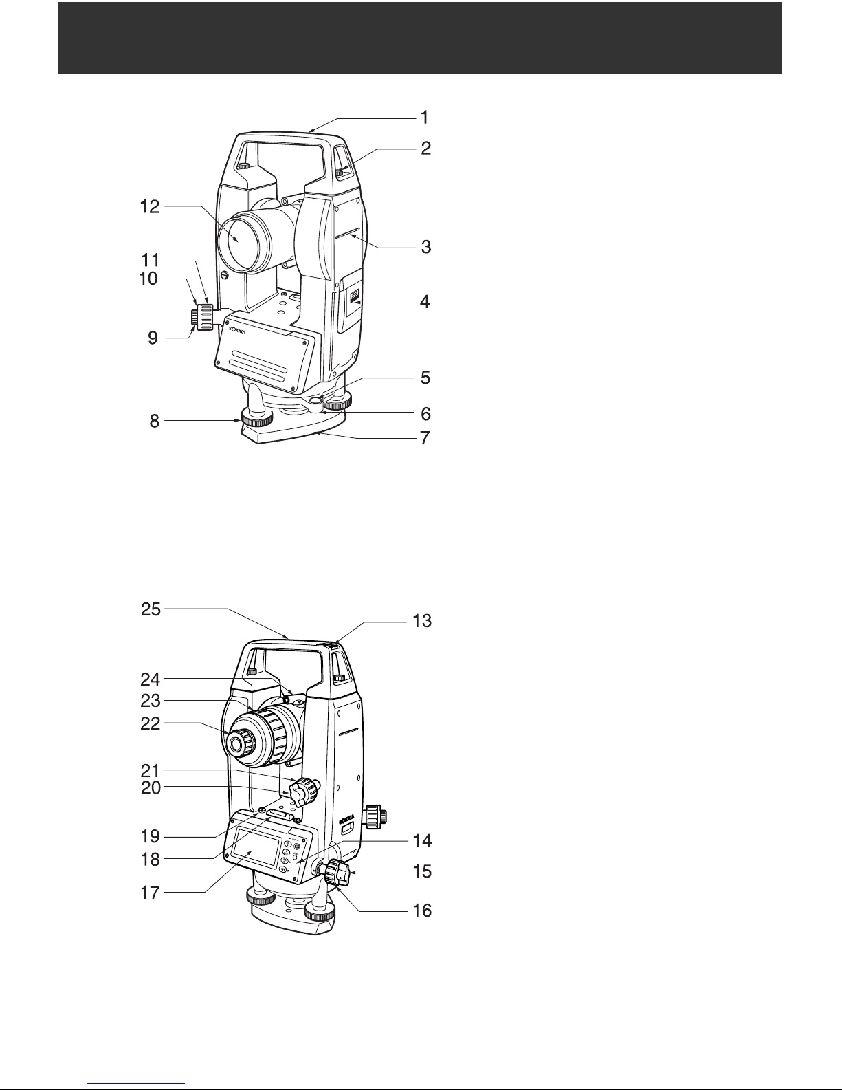
3. PARTS OF THE INSTRUMENT
1. Handle
2. Handle securing screw
3. Instrument height mark
4. Battery cover
5. Circular level
6. Circular level adjusting screws
7. Base plate
8. Leveling foot screw
9. Optical plummet eyepiece
screw
10. Optical plummet reticle cover
11. Optical plummet focusing ring
12. Objective lens
13. Tubular compass slot
14. Operation panel
15. Horizontal clamp
16. Horizontal fine motion screw
17. Display
18. Plate level
19. Plate level adjusting screw
20. Vertical clamp
21. Vertical fine motion screw
22. Telescope eyepiece screw
23. Telescope focusing ring
24. Peep sight
25. Instrument center mark
7
3. PARTS OF THE INSTRUMENT
& Peep sight
Use peep sight to aim the DT in the direction of the measurement point.
Turn the instrument until the triangle in the peep sight is aligned with the
target.
& Instrument height mark
The height of the DT is 236mm (from tribrach dish to this mark). "Instrument
height" is input when setting instrument station data and is the height from the
measuring point (where DT is mounted) to this mark.
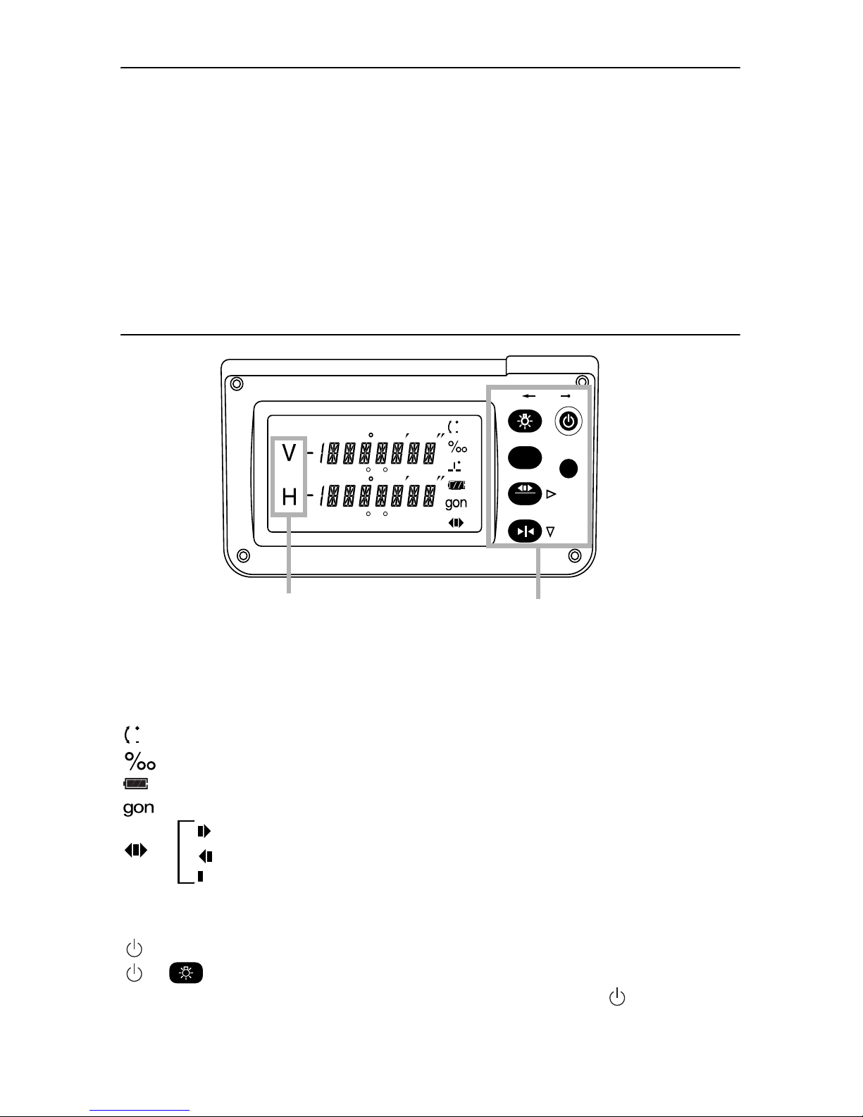
Operation panel ~ Display Functions ~
z Display symbols
P.SAVE: Power saving mode. Deactivated by key operation or rotation of the
upper part of the instrument.
: Vertical angle ±90
: %/‰ vertical angle
: Remaining battery power display (4 levels)
: gon angle units
Horizontal angle right
: Horizontal angle left
Horizontal angle hold
z
Key Operation
: Power on
+:Power off
The ON/OFF power setting may be set so that by itself can
be used to turn the power on and off.
0
SET
%
MENU
OFF
P.SAVE
V: Vertical angle
H: Horizontal angle
Operation keys

3. PARTS OF THE INSTRUMENT
8
C"9. CHANGING INSTRUMENT OPTIONS"
: Select horizontal angle display mode/vertical angle display mode
C"8.3 Changing Horizontal Angle Display Mode" and
"8.4 Changing Vertical Angle Display Mode"
: Display illumination ON/OFF
(Hold for a moment):
Continue holding down the button until "the horizontal angle
beep" has or has not been set.
The setting can also be changed with the setting screen.
C"9. CHANGING INSTRUMENT OPTIONS"
: Set horizontal angle to 0
C"8.1 Measuring the horizontal angle between 2 points (H
angle 0)"
: Hold/release horizontal angle
C"8.2 Set Horizontal Circle to a Required Value (Horizontal
angle hold)"
{MENU} : Enter Item screen.
C"9. CHANGING INSTRUMENT OPTIONS"
9
4. INSTALLING/REMOVING THE BATTERY
Mount the new batteries.
G
• When removing the batteries, turn the power off.
• When installing/removing the batteries, make sure that moisture or dust
particles do not come in contact with the inside of the instrument.
• Use alkaline batteries. If batteries other than alkaline batteries are used, the
battery reserve display and the 'Low' warning will not function properly.
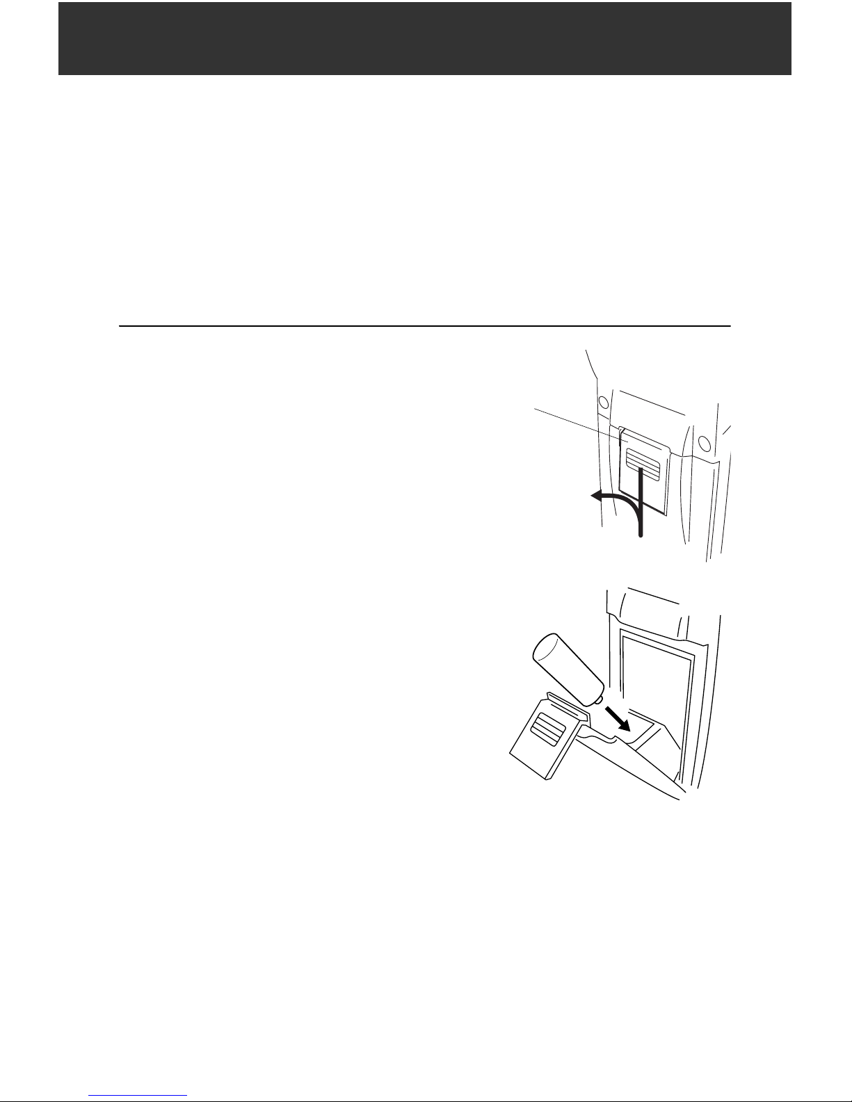
XPROCEDURE
1. Open the battery cover.
2. Insert 2 batteries (LR14/C).
Insert the batteries as depicted by the
illustration on the inside of the battery
cover.
Press the battery
release button downward
Battery
release button
Firmly insert the batteries after verifying
the direction in which they go.
 Loading...