

Sokkia DT5, DT5S, DT5A, DT5AS Operating Manual
.ni
"
-,
SURVEYING INSTRUMENTS,';
SQKKIJ\ DT5/DT5S
DT5A/DT5AS
Electronic Digital Theodolite
OPERATOR'S MANUAL
'~
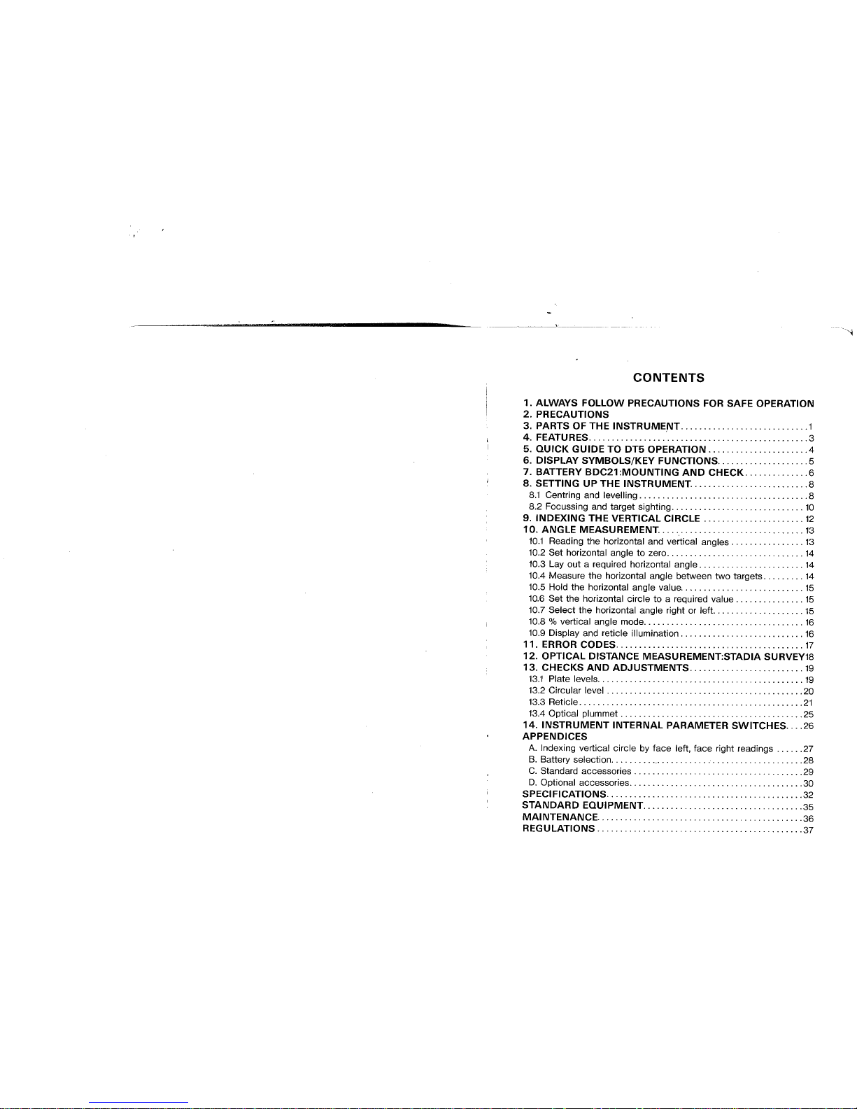
CONTENTS
1. ALWAYS FOLLOW PRECAUTIONS FOR SAFE OPERATION
2. PRECAUTIONS
3. PARTS OF THE INSTRUME,NT............................1
4. FEATU R ES. . .. . .. .. . .. . .. . . .. . .. . .. . . .. .. . .. . .. . .. . .. .. . .. 3
5. QUICK GUIDE TO DT5 OPERATION......................4
6. DISPLAY SYMBOLS/KEY FUNCTIONS. . . . . . . . . . . . . . . . . . . .5
7. BATTERY BDC21:MOUNTING AND CHECK..............6
8. SETTING UP THE INSTRUMENT..........................8
8.1 Centring and levelling. . . . . . . . . . . . . . . . . . . . . . . . . . . . . . . . . . . . .8
8.2 Focussing and target sighting. . . . . . . . . . . . . . . . . . . . . . . . . . . . . 10
9. INDEXING THE VERTICAL CIRCLE. . . . . . . . . . . . . . . . . . . . . . 12
10. ANGLE MEASUREMENT................................ 13
10.1 Reading the horizontal and vertical angles. . . . . . . . . . . . . . . . 13
10.2 Set horizontal angle to zero. . . . . . . . . . . . . . . . . . . . . . . . . . . . . . 14
10.3 Layout a required horizontal angle. . . . . . . . . . . . . . . . . . . . . . . 14
10.4 Measure the horizontal angle between two targets. . . . . . . . . 14
10.5 Hold the horizontal angle value. . . . . . . . . . . . . . . . . . . . . . . . . . . 15
10.6 Set the horizontal circle to a required value. . . . . . . . . . . . . . . 15
10.7 Select the horizontal angle right or left. . . . . . . . . . . . . . . . . . . . 15
10.8 % vertical angle mode. . . . . . . . . . . . . . . . . . . . . . . . . . . . . . . . . . . 16
10.9 Display and reticle illumination. . . . . . . . . . . . . . . . . . . . . . . . . . . 16
11. ERROR CODES. .. . .. . .. . . .. . .. . . .. . .. . . . .. . .. . .. . .. . .. . 17
12. OPTICAL DISTANCE MEASUREMENT:STADIA SURVEY18
13. CHECKS AND ADJUSTMENTS. .. . .. . .. . .. . .. . .. . .. .. . . 19
13.1 Plate levels. . . . . . . . . . . . . . . . . . . . . . . . . . . . . . . . . . . . . . . . . . . . . 19
13.2 Circular level. . . . . . . . . . . . . . . . . . . . . . . . . . . . . . . . . . . . . . . . . . .20
13.3 Reticle. . . . . . . . . . . . . . . . . . . . . . . . . . . . . . . . . . . . . . . . . . . . . . . . .21
13.4 Optical plummet. . . . . . . . . . . . . . . . . . . . . . . . . . . . . . . . . . . . . . . .25
14. INSTRUMENT INTERNAL PARAMETER SWITCHES... .26
APPENDICES
A. Indexing vertical circle by face left, face right readings. . . . . .27
B. Battery selection. . . . . . . . . ',' . . . . . . . . , . " . . . . . . . . . . . . , . , . . . .28
C. Standard accessories. . . . . . . . . . . . . . . , . . . . . . . . . . . . . . , , . . . . .29
D. Optional accessories........,............."............. .30
SPECiFiCATIONS..,............."..............,......... .32
STANDARD EQUIPMENT. . . . . . . . . . . . . . . . . . . . . . . . . . , . . . . . . . .35
MAINTENANCE..............,...............,.".......... .36
REGULATIONS.",.............,.".............",....... .37
1. ALWAYS FOLLOW PRECAUTIONS FOR SAFE
OPERATION
For the safe use of the product and prevention of injury to operators
and other persons as well as prevention of propert damage, items
which should be observed are indicated in both the operator's manual
and on the product itself.
Definition of Indication
Ignoring this indication and making an operation
& Warning error could possibly result in death or serious injury
to the operator
&. Caution
Ignoring this indication and
error could possibly result
propert damage
making an operation
in personal injury or
Safety guidelines for using DT5/DT5S/DT5A/DT5AS
& Warning
. Never look at the sun through the telescope. Loss of eyesight
could result.
. Personnel other than qualified service engineers should not perform
disassembly, rebuilding or repair. Fire, electric shock or burns
could result.
. Do not use the unit in areas exposed to high amounts of dust or
ash, in areas where there is inadequate ventilation, or near
combustible materials. An explosion could occur.
& Caution
. Do not use the carrying case as a footstool. The case is slippery
and unstable so a person could slip and fall off it.
. Secure the handle to the main unit with locking screws. Failure
to properly secure the handle could result in the unit falling off
while being carried, causing injury.
"~
. Tighten the tribrach securely. Failure to properly secure the handle
could result in the unit falling off while being carried, causing injury.
. When mounting the instrument to the tripod, tighten the centring
screw securely. Failure to tighten the screw properly could result
in the instrument falling off the tripod causing injury.
. Tighten securely the leg fixing screws of the tripod on which the
instrument is mounted. Failure to tighten the screw properly
could result in the instrument falling off the tripod causing injury.
. Do not carry the tripod with the tripod shoes pointed at other
persons. A person could be injured if struck by the tripod shoes.
. Check that hands and feet are not in the vicinity of the tripod
legs when erecting the tripod. A hand or foot stab wound could
occur.
. Do not place the instrument in a case with a damaged catch, belt
or handle. The case or instrument could be dropped and cause
injury.
. Do not wield or throw the plumb bob. A person could be injured
if struck.
Safety guideline for using battey
& Warning
. Do not use the battery if wet. Resultant shorting could lead to
fire or burns.
2. PRECAUTIONS
a) When the DT5 is not used for a long time, check it at least once every
three months.
b) Handle the DT5 with care. Avoid heavy shocks or vibration.
c) If any problems are found with the rotatable portion, screws or optical
parts ( e.g. lens), contact your SOKKIA agent.
d) After removing the DT5 from the carrying case, close the case to
exclude dust.
e) Never place the DT5 directly on the ground. (Attached dirt may
damage the base plate and centering screw.)
f) Never carry the DT5 on the tripod to another site.
g) Protect the DT5 with an umbrella against strong sunlight and rain.
h) When the operator leaves the DT5, the vinyl cover should be placed
over the instrument.
i) Always switch the power off before removing the battery.
j) Always remove the battery from the DT5 before returning it to the
case.
k) When the DT5 is placed in the carrying case, follow the layout plan.
i) Make sure that the DT5 and the protective lining of the carrying case
are dry before closing the case. (The case is hermetically sealed;
if moisture is trapped inside, damage to the instrument could occur.)
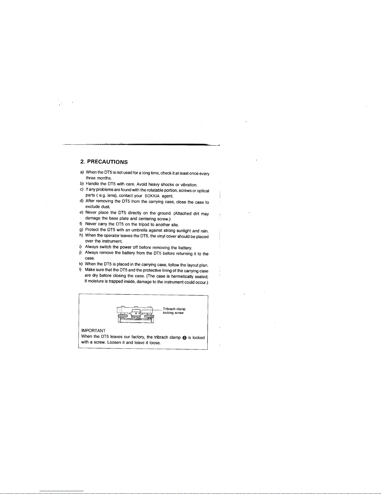
Tribrach clamp
locking screw
IMPORTANT
When the DT5 leaves our factory, the tribrach clamp 0 is locked
with a screw. Loosen it and leave it loose.
-,
-,

:" ":"i,.'~:;,,n; _.-.
3. PARTS OF THE INSTRUMENT
o Handle
8 Instrument height mark
8 Internal switch cover
~
ø Display
o Keyboard
o Tribrach
f) Levelling foot screw
tl Tribrach clamp
o Base plate
4I Circular level adjusting
screws
QJ
0
4D
0
f)
4D
0
tl
K)
Kj
~
KD
4D Circular level
4f Optical plummet eyepiece
æ Optical plummet reticle ad-
justment cover
æ Optical plummet focussing
ring
æ Objective lens
~ Handle securing screw
~
fl
~
fl
fl
*Above figures are DT5.
-1 -
4D Tubular compass slot
lI Battery release cover
æ Battery BDC21
W Plate level adjusting screw
~ Plate level
f1 Power switch
~ Data output connector
fZ Horizontal fine motion screw
~ Horizontal clamp
fI Plate level
o Plate level adjusting screw
W Vertical clamp
fj Vertical fine motion screw
KI Telescope eyepiece
~ Telescope reticle adjust-
ment cover
~ Telescope focussing ring
~ Peep sight
Cl Field of view illumination
lever
-2-
"
4. FEATURES
. The DT5 is a highly-accurate electronic digital theodolite. Horizontal
and vertical angles are simultaneously displayed on an easy-to-read
LCD display.
. A self-diagnostic function is provided; a microcomputer constantly
checks the angle-measuring function. If the instrument is not
functioning correctly, an error code is displayed.
. Any standard "AN size çatteries, rechargeable Ni-Cd or alkaline type
(i.e. LR6 or R6P) batteries can be used.
. The built-in reticle and display lighting is useful for surveying at night
or in underground work.
. A power saving cut-off function can be selected, which switches
the instrument power off 30 minutes after the last key operation to
save battery power.
. An R8-232C data-output connector is provided, to allow the horizon-
tal and vertical angle data to be output to a data collector or external
computer.
. The DT5 is provided with a removable tribrach base, while the DT58
has a shifting-style tribrach for quick centring.
-3-
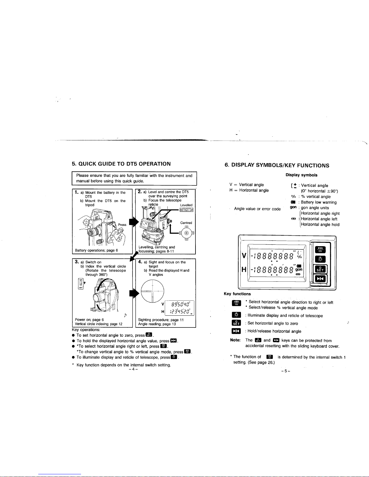
5. QUICK GUIDE TO DT5 OPERATION
Please ensure that you are fully familiar with the instrument and
manual before using this quick guide.
1. a) Mount the battery in the
OT5
b) Mount the OT5 on the
tripod
Battery operations; page 6
3. a) Switch on
b) Index the vertical circle
(Rotate the telescope
through 360")
~T
2. a) Level and centre the OT5
over the surveying point
b) Focus the telescope
reticle Levelled
I!I: 1;""0,,,101
i
4. a) Sight and focus on the
target
b) Read the displayed Hand
V angles
ED
V
H
89'50''-0''
,-i-i'ur':,n"
ie 'Ji:;,_ LI I~
ji
Power on; page 6
Vertical circle indexing; page 12
Key operations:
. To set horizontal angle to zero, press H .
. To hold the displayed horizontal angle value, press c:.
. "To select horizontal angle right or left, press..
"To change vertical angle to % vertical angle mode, press..
. To illuminate display and reticle of telescope, press..
Sighting procedure; page 11
Angle reading; page 13
" Key function depends on the internal switch setting.
-4-
.."
6. DISPLAY SYMBOLS/KEY FUNCTIONS
Display symbols
v = Vertical angle
H = Horizontal angle
(~ : Vertical angle
(0° horizontal ::90")
0/0 : % vertical angle
. : Battery low warning
go : gon angle units
r Horizontal angle right
~.~ :iHorizontal angle left
Horizontal angle hold
Angle value or error code
\
/
/
\
/
.
V
o , ,to ( .
_ I ci ci i-' i-' i-' i-' n '
.
I ,_, i_' ei ei ei ei ei 0/0
.
.
H
o , "'.
II
_icicicinnnngo
I LI i_' i_' ei ei II II
. .
- - ~.~
1m
/
\
-.,
/
-
,
Key functions
.
.
II
1m
" Select horizontal angle direction to right or left
" Select/release % vertical angle mode
: Iluminate display and reticle of telescope
: Set horizontal angle to zero
: Hold/release horizontal angle
The Hand c: keys can be protected from
accidental resetting with the sliding keyboard cover.
Note:
" The function of . is determined by the internal switch 1
setting. (See page 26.)
-5-

7. BATTERY BDC21 :MOUNTING AND CHECK
Battery
release
cover
Release
button
Guide pin
~T
v -: B B BOS 8'8 S" 1/~
. , ".
H -:E:E:E~E~888~
i
V
H
1-'
'-'
I .-, :'
Ci .-, .'
1
V
H
,-,
'_I
.., ,., I-I I-I I-I
,_, LI ,_, I_I ,_,
"
1) Ensure that the power switch ~ is OFF.
2) Mounting the battery:
a) Insert the bottom of the battery into the
battery recess.
b) Press the top of the battery unti a click is
heard.
c) Close the battery release button cover lI.
3) Removing the battery:
a) Open the battery release cover lI.
b) Press the release button downwards.
c) Remove the battery.
Jl
4) Instrument and battery check:
Turn the DT5 power switch ~ on.
The audio tone sounds and all the display
symbols are shown on the display while the
instrument performs self-diagnostic checks.
Jl
When the instrument has successfully com-
pleted the checks, the remaining battery
power is displayed as a numeric code for
three seconds:
Code 0
Less than
(e.g. R6P batter-
1.5 hrs
ies at 25"C)
1
1.5-10 hrs
2 1 0-15 hrs
3 More than
1 5 hrs
The display of 0 in the V display indicates
that the instrument is ready for vertical circle
indexing.
-6-
,-
-----~--_.--------
:D
&~
~
~'J~O., :~
~, '
'~.. ,
",
When the. symbol is displayed, the
batteries should be replaced.
Turn the power switch off and replace the
dry cell batteries in the battery case as
follows:
5) Changing the dry cell batteries:
Remove the battery from the DT5.
Push down and slide open the battery
case cover. Install the four new "AA"
size batteries in the directions indicated
inside the case.
-7-
 Loading...