

Page 1

1
Operator Manual
Betriebsanleitung
Guide de lopérateur
WARNING
U Drive 25
U Drive 25
SERIAL NO. 1001 TO CURRENT
Manual del operador
operating instructions before performing maintenance on or operating any
All personnel shall carefully read, understand and follow all safety rules, and
UpRight aerial work platform.
Refer to page 2 for the English language version of this Operator Manual.
WARNUNG
AVERTISSEMENT
Wartungsarbeiten ausführen oder diese in Betrieb nehmen.
sécurité avant dentretenir ou dutiliser une plate-forme élévatrice UpRight.
Tout le personnel doit lire attentivement et respecter toutes les consignes de
Reportez-vous à la page 11 pour la version française de ce guide de lopérateur.
Alle Bediener müssen die Sicherheitsregeln und Bedienungsanleitungen gründlich
durchlesen, verstehen und befolgen, bevor sie an irgendeiner UpRight-Hocharbeitsbühne
Bezüglich der deutschsprachigen Ausgabe dieser Betriebsanleitung siehe Seite 20.
ADVERTENCIA
seguridad, las instrucciones de operación antes de efectuar trabajos de
mantenimiento o manejar cualquier plataforma aérea de trabajo UpRight.
Todo el personal debe leer atentamente, entender y respetar todas las reglas de
Referirse a la página 29 para la versión en español de este manual del operador.
7/99 K
069316-020
FOR MORE INFORMATION
Tel.: (800) 926-5438 or (209) 891-5200
Fax: (209) 896-9012
1775 Park St., Selma, CA 93662
Tel: (353) 1-285-3333
Fax: (353) 1-284-0015
USA
EUROPE
Pottery Road, Dun Laoire, Ireland
Pour de plus amples informations
É.-U.
Téléphone : (800) 926-5438 ou (209) 891-5200
Télécopieur : (209) 896-9012
1775 Park St., Selma, CA 93662
Téléphone : (353) 1-285-3333
Télécopieur : (353) 1-284-0015
Pottery Road, Dun Laoire, Irlande
EUROPE
Tel.: (800) 926-5438 oder (209) 891-5200
Fax: (209) 896-9012
1775 Park St., Selma, CA 93662
Tel.: (353) 1-285-3333
Fax: (353) 1-284-0015
Für weitere Informationen
USA
EUROPA
Pottery Road, Dun Laoire, Irland
Para obtener más información
Tel.: (800) 926-5438 ó (209) 891-5200
Fax: (209) 896-9012
EE.UU.
1775 Park St., Selma, CA 93662
Tel.: (353) 1-285-3333
EUROPA
Fax: (353) 1-284-0015
Pottery Road, Dun Laoire, Irlanda
44
Page 2
43
NOTES:
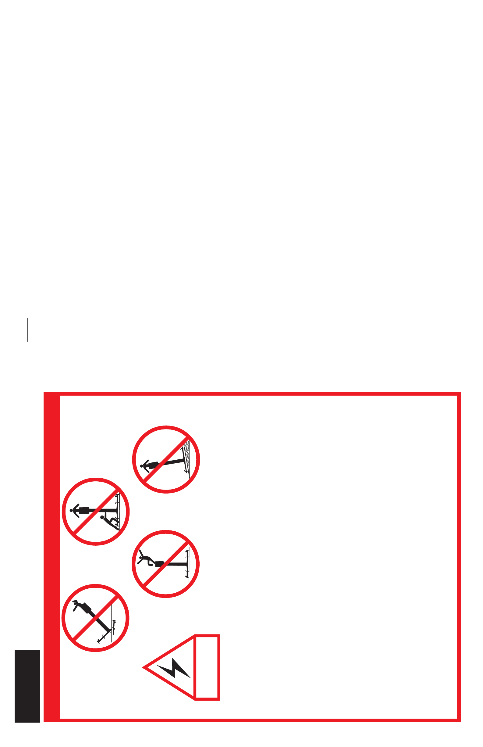
the UpRight Lift with
NEVER attempt to push
people or materials on
platform elevated.
the platform or with the
NEVER elevate platform without
first leveling the base.
NOTE: The placement and movement of the machine with the platform raised is
permitted on smooth, firm surfaces with sufficient load carrying capacity only, the
inclination of which shall not exceed 1.0 degrees.
Section
English Language
SAFETY RULES
NEVER elevate
platform unless all
four (4) outriggers
have been properly
installed. All wheels or
Climbing up on the railing of the platform,
standing on or stepping from the platform
onto buildings, steel or prefab concrete
structures, etc., is prohibited.
NOT INSULATED.
THIS MACHINE IS
screwjacks must be in
solid contact with a firm
surface before the
platform is elevated.
Use of the Aerial Work Platform: This aerial work platform is intended to lift one person and his tools as well as the
material used for the job. It is designed for repair and assembly jobs and assignments at overhead workplaces (ceilings,
cranes, roof structures, buildings, etc.). All other uses of the aerial work platform are prohibited.
MACHINE must be driven only on smooth level floor surface.
This aerial work platform is not insulated! For this reason it is imperative to keep a safe distance from live parts of
electrical equipment.
To extend the height or the range by placing ladders, scaffolds or similar devices on the platform is prohibited.
NEVER attach overhanging loads to the platform or increase the platform size.
Exceeding the specified permissible maximum load of 159 kg (350 lbs) or the presence of more than one person on the
platform is prohibited.
LOOK up, down and around for overhead obstructions and electrical conductors.
To bypass any safety equipment is prohibited and presents a danger for the persons on the aerial platform and in its
working range.
NEVER use outriggers from one model on another model.
Dismantling the folding entry railing or other railing components is prohibited! Always make certain that the entry
folding rail is closed and securely locked!
It is prohibited to keep the entry folding rail in an open position (e.g. held open with tie straps) when the platform is
raised!
INSPECT the machine thoroughly for cracked welds, loose or missing hardware, hydraulic leaks, damaged control or
power cables and loose wire connections.
The use and operation of the aerial work platform as a lifting tool (lifting of loads from below upwards or from up high on
down) is prohibited!
NEVER recharge battery near sparks or open flame. Batteries that are being charged emit highly explosive hydrogen
gas.
AFTER USE secure the work platform against unauthorized use by turning key switch off and removing key.
Modifications to the aerial work platform are prohibited or permissible only by the approval of UpRight.
The attachment or the use of components not manufactured or supplied by UpRight is prohibited!
NEVER use machine as a welding ground. Welding ground must be attached to same structural element which is being
repaired.
2
Page 3
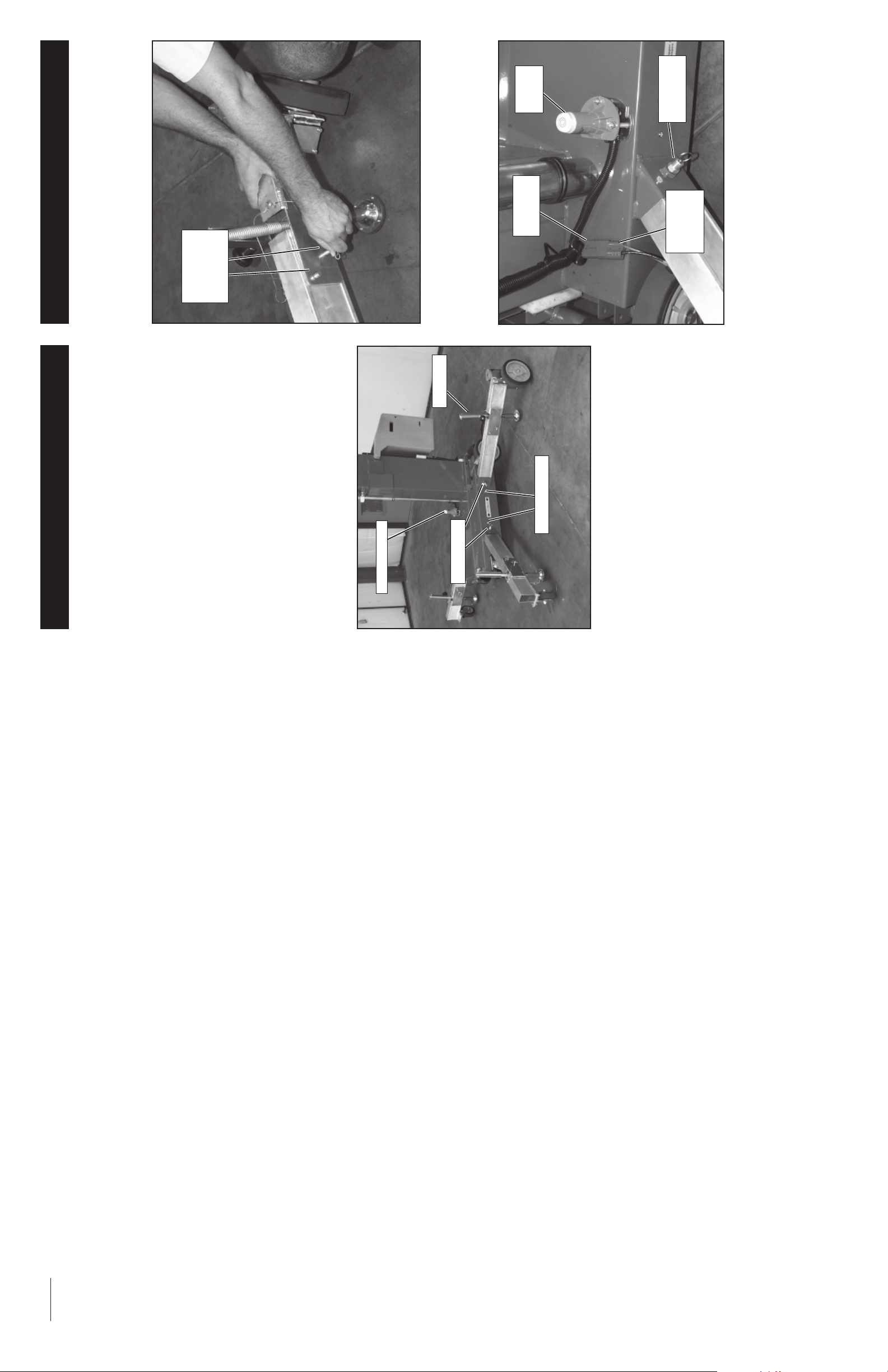
Wheel Installation
screwjacks clockwise until wheels can be
installed.
wheels in place using pins provided.
1. After outriggers have been installed, turn
2. Install rear wheels into rear outriggers. Pin
pins
Wheel
connecting
Figure 2: Installing wheels
3. Plug connector from rear wheels into connector
Level
Sensor
Base
Connector
from chassis wiring.
Lock Pin
Outrigger
Rear
Wheel
Connector
3
Figure 3: Connecting rear wheel cables
Outrigger Installation
on sides of mast.
1. Remove the outriggers from storage locations
2. Insert into outrigger socket in base (Figure 1).
outrigger. Pull outward on outrigger to ensure
engagement.
3. Push in until locking pin engages hole in end of
Make sure all four (4) locking pins are engaged.
level on the base by adjusting the screwjacks at
4. Repeat the above steps for all other outriggers.
5. Level the base, centering the bubble in the orbit
the end of each outrigger (Figure 1). DO NOT
release the tension on an outrigger, by turning
Level Sensor
counterclockwise, to level base.
IMPORTANT: All four (4) screwjack pads must be
in solid contact with a firm surface and each outrig-
ger indicator light must be lit before the platform is
elevated.
Screwjack
Locking Pin
Indicator Light
Figure 1: Installing outriggers
NOTES:
42
Page 4
41
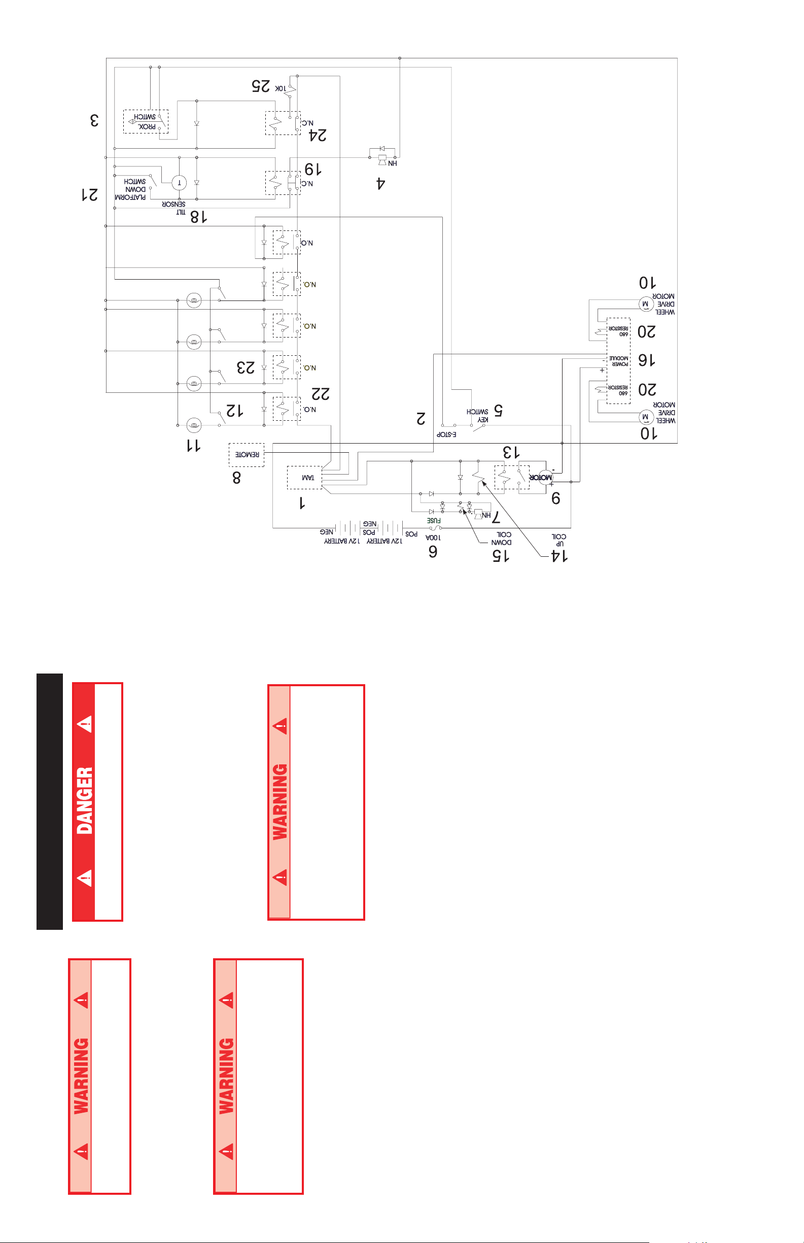
U-Drive 25 Electrical Schematic - 069304-000
Pre-Operation & Safety Test
using pins provided.
4. Install front wheels. Pin front wheels in place
NEVER perform this test from the platform.
1. On a solid level surface, install outriggers and
BE SURE all wheels are securely attached.
Pull on wheels to check for loose pins.
5. Lower screwjacks (turn counterclockwise) until
wheels.
hydraulic tank and check for proper hydraulic oil
2. Lower platform completely. Remove fill cap on
wheels are resting on ground. Be sure
screwjacks are high enough to avoid inter-
level.
ference with the ground when machine is
driven.
pushing level sensor out of alignment. Listen for
3. Activate lift function on platform controller while
DO NOT use a machine that elevates when
level sensor is off of level or tension has
been released on an outrigger. Remove
machine from service and repair before
audible tilt alarm.
4. Platform should not elevate.
DO NOT use machine if screwjack limiting
tubes have been removed. Remove ma-
chine from service and repair before
using.
IMPORTANT: All four wheels must be in solid
using.
contact with the ground and each outrigger indica-
tor light must be lit before the machine is operated.
straps. Check for missing or loose parts.
5. Release level sensor and fully elevate platform.
6. Visually inspect elevating assembly, chains and
lowering alarm.
for proper operation. To close Emergency
Lowering Valve, turn the knob until it snaps
7. Partially lower platform and listen for audible
8. Turn Emergency Lowering Valve knob to check
back in.
4
Page 5
5
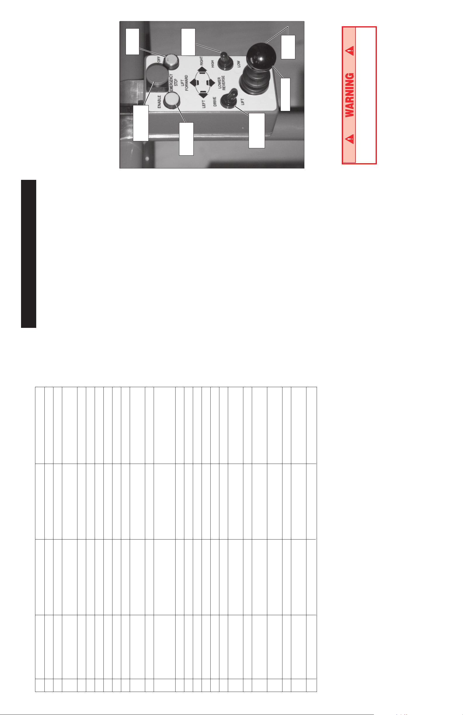
8. Push ON/OFF button. Green LED will blink.
9. Adjust Drive/Lift and High/Low switches for
desired operation.
ahead or back to move or raise machine.
10.Holding Enable button down, push joystick
NOTE: Move joystick right or left while driving
forward or backwards to turn machine. Machine
will only drive at high speed when platform is
fully lowered.
NOTE: High/Low switch affects drive speed
only. Lift/Lower speed is constant.
Button
ON/OFF
Emergency
Stop Button
Switch
High/Low
Button
Enable
Switch
Drive/Lift
Horn
Button
Joystick
Figure 4: Platform Controls
IMPORTANT: Machine is designed to travel on
smooth flat surfaces only.
If the platform should fail to lower, NEVER
climb down the mast.
before lowering the platform.
11. Check that the area below the platform is clear
turning Key Switch to OFF and removing key.
12. After use, secure unit from unauthorized use by
Operation Using Wheels
this machine.
The operator has been thoroughly trained on
Before operating the machine, be sure that:
follows this Operator Manual and the Scaffold
The operator has read, fully understands, and
Industry Association's MANUAL OF
RESPONSIBILITIES.
outriggers and wheels properly installed and
machine has passed the Safety Interlock
Test (page 6).
The unit has been properly set up with all
NOTE: Platform will not elevate unless all four
outriggers and wheels are properly installed
with wheels firmly in contact with floor and
each outrigger indicator lamp lit.
de las ruedas
1. Check for external damage to the mast.
2. Turn Key to ON, Key Switch is located on the left
side of the mast (Figure 4).
located on the left side of the mast, to turn switch
ON.
3. Pull out on Lower Emergency Stop Button,
before elevating the platform.
IMPORTANT: In the event of an emergency
push the button in to cut power to all controls.
4. Check that the area above the platform is clear
Enter the platform.
5. Release latch and raise upper half of cage.
platform making sure latch is engaged.
6. Lower upper half of the cage after entering
platform control panel.
7. Pull out on Emergency Stop Button, located on
de proximité
U-Drive 25 Electrical Schematic - 069304-000
ENGLISH FRANÇAIS GERMAN SPANISH
1 Control Module Module de commande Steuermodul Módulo de control
2 E-Stop Arrêt darrêt durgence Notaustaster Parada de emergencia
3 Proximity Switch Commutateur Näherungsschalter Interruptor de proximidad
4 Tilt Alarm Alarme dinclinason Neigungswarnung Alarma de inclinación
5 Key Switch Interrupteur à clé Schlüsselschalter Interruptor de la llave
6 100A fuse Fusible, 100A Sicherung 100 A Fusible de 100 AMP
7 Down Alarm Alarme, abaissée Senkwarnung Alarma abajo
8 Platform Module Module de la plate-forme Plattformmodul Módulo de la plataforma
9 Motor Moteur Motor Motor
10 Motor, Wheel Drive Moteur, roues motrices Motor, Radantrieb Motor, accionamiento
Interlock chement solidaire, Hilfsstützensperre Enclavamiento
11 Lamp, Indicator Témoin lumineux Kontrolleuchte Lámpara, indicador
12 Switch, Outrigger Interrupteur denclen- Schalter, Interruptor, Estabilizador
stabilisateurs
13 Relay, Motor Relais, moteur Relais, Motor Relé, motor
14 Coil, Up Bobinage, élév. Spule, aufwärts Bobina, elevación
15 Coil, Down Bobinage, abaiss. Spule, abwärts Bobina, descenso
16 Power Module Bloc de puissance Antriebseinheit Módulo de alimentación
17 Battery Batterie Batterie Batería
18 Level Sensor Capteur de niveau Niveausensor Sensor de nivel
19 Relay Contact Contact de relais Relaiskontakt (Öffner) Contacto del relé
plate-forme de la plataforma
Normally Closed normalement fermé normalmente cerrado
20 Resistor (680) Résistance (680) Widerstand (680) Resistencia (680)
21 Platform Down Switch Interrupteur dabaiss., Plattform-Absenkschalter Interruptor de descenso
Normally Open normalement ouvert Normalmente abierto
22 Relay Contact Contact de relais Relaiskontakt (Schließer) Contacto de relé
23 Diode Diode Diode Diodo
24 Relay Contact Contact de relais Relaiskontakt (Öffner) Contacto del relé
Normally Closed normalement fermé normalmente cerrado
25 Resistor (10K) Résistance (10K) Widerstand (10K) Resistencia (10K)
40
Page 6
39
NOTES:
under cover.
AFTER USE EACH DAY
1. Ensure that the platform is fully lowered.
2. Park the machine on level ground, preferably
3. Secure against vandals, children or unautho-
If the platform should fail to lower, NEVER
climb down the mast.
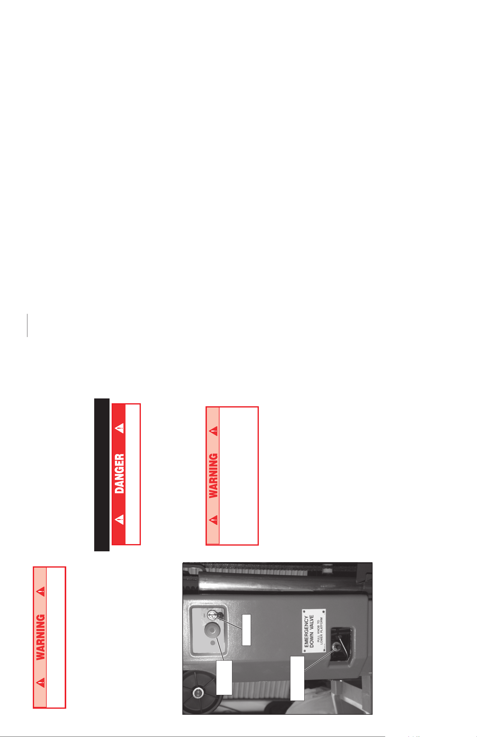
EMERGENCY LOWERING
rized operation by turning the Key Switch to
OFF and removing the key.
Ask a person on the ground to open the Emer-
gency Lowering Valve to lower the platform. This
valve is located through a cutout in the power unit
Safety Interlock Test
cover on the left side of the mast.
1. Pull the knob out and turn one quarter turn
either direction to open the Emergency Lower-
ing Valve.
NEVER perform this test from the platform.
the knob until it snaps back in.
2. To close the Emergency Lowering Valve, turn
base using screwjacks.
1. Properly install all four (4) outriggers and level
2. Release the tension on one (1) outrigger by
NOTE: Once the platform is fully lowered, be
certain that the Emergency Lowering Valve is
closed again. The platform will not elevate if the
turning the screwjack counterclockwise, until the
indicator lamp is no longer lit.
Emergency Lowering Valve is open.
3. Activate lift switch on side of mast to elevate the
DO NOT use a machine that elevates when
tension has been released on an outrigger.
Remove machine from service and repair
platform. Platform should not elevate.
Emergency
Stop Button
before using.
Key Switch
repeat step 2 with another outrigger.
4. Re-level the base with all four (4) outriggers then
have been tested.
5. Repeat steps 2 , 3 & 4 until all four (4) outriggers
Figure 5: Base Controls
Emergency
Lowering Valve
6
Page 7
If the platform should fail to lower, NEVER
climb down the mast.
EMERGENCY LOWERING
Ask a person on the ground to open the Emer-
gency Lowering Valve to lower the platform. This
valve is located through a cutout in the power unit
cover on the left side of the mast (Figure 5).
/4 turn to open the
1
1. Pull the knob out and turn
Emergency Lowering Valve.
2. To close the Emergency Lowering Valve, turn
the knob until it snaps back in.
Once the platform is fully lowered, be certain that
the Emergency Lowering Valve is closed again.
The platform will not elevate if the Emergency
Lowering Valve is open.
AFTER USE EACH DAY
under cover.
1. Ensure that the platform is fully lowered.
2. Park the machine on level ground, preferably
rized operation by turning the Key Switch to
OFF and remove the key.
3. Secure against vandals, children or unautho-
Battery Maintenance
Hazard of explosive gas mixture. Keep
sparks, flame and smoking materials away
from battery.
Always wear safety glasses when working
with batteries.
Battery fluid is highly corrosive. Rinse away
any spilled fluid thoroughly with clean water.
Always replace battery with UpRight battery
or manufacturer approved replacement
weighing at least 23.6 kg (52 lbs.) each.
Check battery fluid level daily, especially if
work platform is being used in a warm, dry
climate.
in.) above
8
/
3
If electrolyte level is less than 10 mm (
plates add distilled water only. DO NOT use tap
water with high mineral content, it will shorten
battery life.
Keep terminals and tops of batteries clean.
Refer to the Service Manual to extend battery life
and for complete service instructions.
7
Outriggers Only
Operation Using
this machine.
follows this Operator Manual and the Scaffold
Industry Association's MANUAL OF
RESPONSIBILITIES.
The operator has been thoroughly trained on
The operator has read, fully understands, and
Before operating the machine, insure that:
(4) outriggers properly installed and the base
leveled, and the machine has passed the
Safety Interlock Test.
The unit has been properly set up with all four
bomba/motor
Note: Platform will not elevate unless all four
outriggers are properly installed with screwjack
pads firmly in contact with floor and each
outrigger indicator lamp lit.
1. Check for external damage to the mast.
2. Turn Key to ON, Key Switch is located on the left
side of the mast (Figure 5).
located on the left side of the mast, to turn switch
ON. In the event of an emergency push the
3. Pull out on Lower Emergency Stop Button,
button in to cut power to all controls.
lifting up on the upper half of the cage.
4. Enter the platform by releasing the latch and
platform making sure latch is engaged.
5. Lower upper half of the cage after entering
before elevating the platform.
6. Check that the area above the platform is clear
7. Pull out on Emergency Stop Button, located on
platform control panel. In the event of an emer-
gency push the button in to cut power to all
controls.
8. Push ON/OFF button. Green LED will blink.
9. Adjust Drive/Lift switch to Lift position.
ahead to raise machine.
10.Holding Enable button down, push joystick
NOTE: High/Low switch affects drive speed
only. Lift/Lower speed is constant.
before lowering the platform.
11.Check that the area below the platform is clear
turning Key Switch to OFF and remove key.
12.After use, secure unit from unauthorized use by
retour de retorno
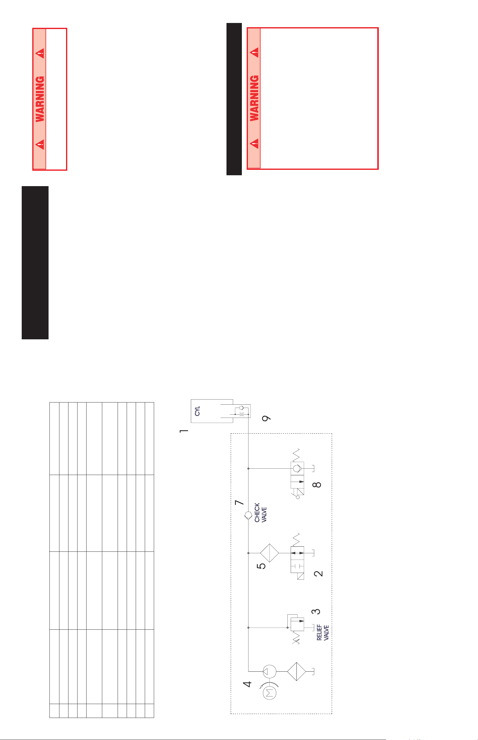
U-Drive 25 Hydraulic Schematic - 068011-000
ENGLISH FRANCAIS GERMAN SPANISH
1 Lift Cylinder Vérin de levage Hubzylinder Cilindro de elevación
2 Bypass Valve Soupape de dérivation Umgehungsventil Válvula de derivación
3 Relief Valve Soupape de décharge Überdruckventil Válvula de alivio
4 Return Line Filter Filtre de canalisation de Rücklauffilter Filtro de la línea
5 Motor/Pump Unit Unité de moteur/pompe Motor-Pumpeneinheit Unidad de la
6 Tank Filter Filtre de réservoir Tankfilter Filtro del depósito
7 Check Valve Clapet de non-retour Rückschlagventil Válvula de comprobación
8 Lift Valve Soupape de levage Hubventil Válvula de elevación
9 Orifice Orifice Drosselblende Orificio
38
Page 8

50 HR 125 HR. 500 HR.
MENSUAL C/3 MESES ANUAL
37
Especificaciones*
ITEM U DRIVE 25
Altura plataforma
Máximo 7,62 m (25 pies)
Mínimo 38 cm (15 pulg.)
Capacidad de la plataforma 159 kg (350 lbs.)
Dimensiones guardada
Alto 1,98 m (79 pulg.)
Ancho 84 cm (29 pulg.)
Largo 1,24 m (49 pulg.)
Superficie de apoyo (sólo gatos de rosca)
Ancho/Largo 1,5 m (59 pulg.)/1,42 m (56 pulg.)
Superficie de apoyo (con ruedas instaladas)
Ancho/Largo 2,1 m (80,5 pulg.)/1,9 m (75 pulg.)
Peso total 409,6 kg (903 lbs.)
Caja de la batería 42,9 kg (94,5 lbs.)
Altura de la baranda 1,1 m (43,5 pulg.)
Altura de barra punta pie 152 mm (6 pulg.)
60 Amp/hr., Peso mín. 23,6 kg (52 lbs.)
Voltaje sistema
Fuente de electricidad CC 2 baterías de 12 volt, grupo 22
60 Hz o 220 volts, corriente alterna, 50 Hz
Alimenta 5 amp, 24 volts, corriente continua
Cargador de batería 120 volts, corriente alterna,
Máxima presión hidráulica del sistema 165 bar (2400 psi)
Velocidad de desplazamiento 0,2 Km/h / 2 MPH
Velocidad de elevación 22 seg.
Inclinación máxima 1 grado
Fuerza máxima del viento 5 escala Beaufort (10,1 m/sec.)
*Las especificaciones pueden cambiarse sin aviso previo.
Cumple o supera los requisitos de las directivas CE y GS sobre
maquinaria.
DIARO O O O
X
Loading
MANTENIMIENTO DE RUTINA
Utilice la siguiente tabla como guía para mantenimiento de rutina. Consulte el Manual de servicio para obtener
OPERACIÓN DE MANTENIMENTO INTERVALO
instrucciones completas sobre serviio de mantenimiento.
Verifique la exactitud del nivel de la burbuja X
Revise la operación de los mecanismos de enganche del estabilizador X
Revise el nivel del fluido de la batería y cargue la batería (modelos CD solamente) X
Verifique que no existan etiquetas dañadas, descoloridas o faltantes y cámbielas X
Revise la condición del cable de control X
Verifique que el ensamblado del mástil no esté doblado, rajado o le falten remaches X
Revise la operación del chasis y del interruptor de parada de emergencia
de la plataforma X
Revise la operación de la válvula de bajada de emergencia X
Verifique que las ruedecillas no presenten daños X
Revise el nivel de fluido hidráulico X
Verifique que la cabina y los sujetadores de soporte de la
cabina tengan el par de torsión adecuado X
Revise y ajuste la tensión de las correas de secuencia X
Lubrique las cadenas de elevación y las roldanas X
Cambie el fluido hidráulico (ISO #46) X
Compruebe las ruedas tractoras para ver si hay piezas sueltas,
perdidas o desgastadas
remove the battery box from the rear of the
machine (Figure 7).
1. Disconnect the plug from the battery box and
BATTERY CHARGING
Charge batteries at end of each work shift or
sooner if batteries have been discharged.
The battery box is heavy, 42.9 kg
Charge battery in a well ventilated area.
Do not charge battery when the work
(94.5 lbs.), lift properly (or have someone
help you) to prevent back injury.
platform is in an area containing sparks or
flames.
Permanent damage to battery will result if not
Make sure loader fully engages tailgate or
vehicle bed.
immediately recharged after discharging.
Keep charger dry.
1. Check battery fluid level. If electrolyte level is
2. Raise the loader support bracket and engage
in.) above plates add
8
/
3
lower than 10 mm (
the retaining pin in the top hole of the loader
distilled water only.
channel (Figure 7).
2. Verify charger voltage switch is set to 12 volts.
3. Connect extension cord (1.5 mm² (12 ga.)
with the gravity hook.
3. Secure the loader to the loader support bracket
4. Position the unit so the back of the machine
conductor minimum and 15 m (50 ft.) in length
maximum) to charger plug.
comes in contact with the vehicle bed or tail-
gate.
Connect extension cord to properly grounded
outlet of proper voltage and frequency.
4. Set charger control to Conventional setting.
down until it comes into contact with the vehicle
5. Release the gravity hook and slide the loader
Charger ammeter should indicate charge rate.
5. When battery is fully charged, charger automati-
bed or tailgate. Then reposition the loader
support bracket so the retaining pin is in the
cally turns itself off. Disconnect extension cord.
first available hole above the loader.
6. Release the locking pin and pull the handle out
until the locking pin engages the hole in the end
of the handle (Figure 8).
pivot, until the unit rotates to a horizontal posi-
7. Lift up on the handle, using the loader as a
Charger Control
Charger
tion in the vehicle bed (Figure 9).
the vehicle bed. The machine will slide on the
loader until the rear wheels are on the bed. The
unit may then be rolled on the rear wheels and
upper casters.
sure the locking pin engages the handle.
8. Push the base of the unit towards the front of
9. Return the handle to the stored position, making
Battery Box Plug
Figure 6: Battery Box
8
Page 9

until the locking pin engages the hole in the end
of the handle.
UNLOADING
1. Unsecure the unit.
2. Release the locking pin and pull the handle out
3. Roll the unit back until the rear wheels are off
the edge of the tailgate or vehicle bed.
4. Pull downward on the handle, allowing the unit
to slide on the loader. As the unit stops sliding
on the loader, it will pivot on the loader to an
upright position. Gradually counterbalance the
units weight by applying an upward force on the
handle. This allows the unit to settle gently on
the wheels, avoiding undue impact on the unit.
sure the locking pin engages the handle.
5. Return the handle to the stored position, making
box plug making certain it is fully engaged.
6. Replace the battery and reconnect the battery
9
Figure 9: Tilting machine onto or off of a vehicle
10.Secure unit with suitable strength rope or tie
straps using forklift pockets located under the
base of the unit and upper caster axle.
To prevent damage to the mast assembly,
do not place rope or tie straps across the
mast assembly when securing the unit for
transportation.
DO NOT overtighten the rope or tie straps,
damage to the machine will result.
Retaining Pin
Loader Channel
Tailgate
Bracket
Loader Support
T-handle
Loader
Locking Pin
Figure 8: Handle positioning
Figure 7: Loader in load position
Gravity Hook
traseras estén fuera de la punta de la compuerta
trasera o de la plataforma del vehículo.
3. Haga rodar la unidad hasta que las ruedas
4. Tire de la palanca hacia abajo, permitiendo que la
unidad se deslice en la cargadora. Cuando la
unidad ya no se deslice en la cargadora, pivotará
en la cargadora a una posición vertical. Gradual-
mente equilibre el peso de la unidad tirando de la
palanca hacia arriba. Esto permitirá que la unidad
se establezca sobre las ruedas delicadamente y
se evita un impacto excesivo en la unidad.
miento, asegurándose de que el pasador traba
enganche en la palanca.
5. Coloque la palanca en la posición de almacena-
6. Cambie la batería, vuelva a conectar la toma de la
caja de la batería y asegúrese de que esté
completamente colocada.
trasera
retención
Pasador de
Abrazadera de
soporte de la
cargadora
Compuerta
Cargadora
Palanca en
forma de T
o fuera del mismo
Figura 9: Inclinar la máquina en un vehículo
seguridad
Pasador de
Para evitar daños al ensamblado del mástil,
no coloque la soga o las correas de amarre
en el ensamblado del mástil al asegurar la
unidad para su transporte.
NO ajuste la soga o las correas de amarre en
exceso, ya que se puede dañar la máquina.
DESCARGA
1. Desasegure la unidad.
2. Quite el pasador traba y tire de la palanca hacia
afuera hasta que el pasador traba se enganche
en el orificio del extremo de la palanca.
cargadora
Canal de la
gravedad
Gancho de
Figura 8: Colocación de la palanca
Figura 7: Cargadora en posición de carga
36
Page 10

Carga
quite la caja de la batería de la parte trasera de la
1. Desconecte la toma de la caja de la batería y
máquina (figura 7).
La caja de la batería es pesada, 42,9 kg
(94,5 lbs.), levántela apropiadamente (o haga
que alguien lo ayude) para evitar lesiones en
la espalda.
Asegúrese de que la cargadora esté
enganchada a la compuerta trasera o a la
plataforma del vehículo.
2 Levante la abrazadera de apoyo de la cargadora y
coloque el pasador de retención en el orificio
superior del canal de la cargadora (figura 7).
de la cargadora con el gancho de gravedad.
3. Asegure la cargadora a la abrazadera de soporte
de la máquina toque la plataforma del vehículo o
la compuerta trasera.
4. Coloque la unidad de modo que la parte trasera
dora hacia abajo hasta que toque la plataforma
del vehículo o la compuerta trasera. Luego vuelva
5. Suelte el gancho de gravedad y deslice la carga-
a colocar la abrazadera de soporte de la
cargadora de modo que el pasador de retención
se encuentre en el primer orificio disponible
sobre la cargadora.
afuera hasta que el pasador traba se enganche
en el orificio del extremo de la palanca (figura 8).
6. Quite el pasador traba y tire de la palanca hacia
pivote, hasta que la unidad rote a la posición
7. Levante la palanca, utilizando la cargadora como
horizontal en la plataforma del vehículo (figura 9).
delantera de la plataforma del vehículo. La
8. Empuje la base de la unidad hacia la parte
máquina se deslizará en la unidad de la cargado-
ra hasta que las ruedas traseras se encuentren en
la plataforma. La unidad puede rodar sobre las
ruedas traseras y las ruedecillas delanteras.
almacenamiento y asegúrese de que el pasador
traba se enganche en la palanca.
9. Vuelva a colocar la palanca a la posición de
resistente o correas de amarre. Emplee las
cavidades para horquillas de carretilla elevadora
situadas bajo la base de la unidad y el eje de
pivotamiento superior.
10.Asegure la unidad con una soga suficientemente
35
CARGA DE LA BATERÍA
Cargue las baterías al final de cada turno de trabajo
o antes si las baterías se descargan.
Cargue las baterías en un área bien ventilada.
No cambie las baterías cuando la plataforma
de trabajo se encuentra en un área en donde
pueden haber chispas o llamas.
Si no se recargan las baterías inmediatamente
luego de la descarga, se pueden producir
daños permanentes.
Mantenga el cargador seco.
pulg.) por
8
/
3
del electrólito es menor a 10 mm (
1. Revise el nivel del fluido de la batería. Si el nivel
encima de las placas, agregue agua destilada
solamente.
voltaje esté colocado en 12 voltios.
2. Verifique que el interruptor del cargador de
mínimo conductor y 15 m (50 pies) de longitud
3. Conecte la correa de extensión 1,5 mm² (12 ga.)
máxima) a la toma del cargador.
Conecte la correa de extensión a una salida a
tierra de voltaje y frecuencia apropiados.
Mando del cargador
Cargador
de la batería
Toma de la caja
Figura 6: Caja de batería
4. Sitúe el mando del cargador en la posición
Convencional. El amperímetro del cargador
debe indicar el régimen de carga.
5. Cuando la batería este completamente cargada,
el cargador se apagará automáticamente.
Desconecte el cable prolongador.
U DRIVE 25
7.62 m (25 ft.)
38 cm (15 in.)
159 kg (350 lbs.)
1.98 m (79 in.)
74 cm (29 in.)
1.24 m (49 in.)
Specifications*
ITEM
Minimum
Platform Capacity
Stored Dimensions
Vertical Height
Width
Platform Height
Maximum
Depth
1.5 m (59 in.)/1.42 m (56 in.)
2.1 m (80.5 in.)/1.9 m (75 in.)
Footprint (screw jacks only)
Width/Length
Footprint (wheels attached)
Width/Length
152 mm (6 in.)
1.1 m (43.5 in.)
42.9 kg (94.5 lbs.)
409.6 kg (903 lbs.)
Weight-overall
Battery Box
Guardrail Height
Toe Board Height
System Voltage
2-12 Volt Battery, Grp. 22
60 Amp/Hrs., Min. Wt. 152 mm (52 lbs.)
DC Electric Power Source
Output: 5 Amps, 24 Volts D.C.
120 VAC 60 Hz or 220 VAC 50 Hz
Battery Charger
165 bar (2400 PSI)
Maximum Hydraulic System
Pressure
22 Seconds
0.2Km/h / 2 MPH
Drive Speed
Raising Speed
1 Degree
Beaufort 5 (10.1 m/sec)
Maximum Slope
Maximum Wind Force
*Specifications subject to change without notice. Meets or exceeds
all applicable CE & GS Machinery Directive Requirements.
50 HRS. 125 HRS. 500 HRS.
MONTHLY 3 MONTHS YEARLY
DAILY OR OR OR
ROUTINE SERVICE
SERVICE OPERATION INTERVAL
Use the following table as a guide for routine maintenance, refer to Service Manual for complete service
instructions.
Check bubble level accuracy X
Check operation of outrigger interlocks X
Check battery fluid level and charge battery (D.C. models only) X
Check for peeling, faded or missing labels & replace X
Check condition of control cable X
Inspect mast assembly for bends, cracks or loose rivets X
Check chassis and platform emergency stop switch operation X
Check emergency lowering valve operation X
Check casters for damage X
Check hydraulic fluid level X
Check cage and cage support fasteners for proper torque X
Inspect and adjust sequence straps slack X
Lubricate lift chains and sheaves X
Change hydraulic fluid (ISO #46) X
Check drive wheels for loose, missing or worn parts X
10
Page 11

élévatrice UpRight
pousser la plate-forme
NE JAMAIS tenter de
lorsque la plate-forme
est élevée ou que des
personnes ou de
léquipement sy
trouvent.
NE JAMAIS élever la plate-
forme sans avoir dabord
mis la base de la machine à
lhorizontale.
11
NOTA : La mise en place et le déplacement de lengin, plate-forme élevée, ne
sont permis que sur des surfaces solides et lisses, dune capacité portante
suffisante et dont la pente ne doit pas dépasser 1,0 degré.
RÈGLES DE SÉCURITÉ
Version française
Il est interdit de monter ou de se tenir debout
sur les garde-corps de la plate-forme, ou de se
servir de la plate-forme pour monter sur des
bâtiments, des structures dacier ou de béton
préfabriqué, etc.
CETTE MACHINE
NE JAMAIS élever la
plate-forme sans que
les quatre (4)
stabilisateurs ne
soient solidement
fixés en place. Avant
de lélever, sassurer
que tous les pieds
réglables à vis des
stabilisateurs sappuient
fermement contre une surface
solide.
N'EST PAS ISOLÉE.
Utilisation de la plate-forme élévatrice de travail : Cette plate-forme élévatrice de travail est conçue pour lever une (1) personne et ses outils, ainsi
que le matériel utilisé pour la tâche à accomplir. Elle est conçue pour permettre lexécution de tâches et de travaux de réparation et dassemblage
en des endroits surélevés (plafonds, ponts roulants, structures de toit, bâtiments, etc.). Il est interdit dutiliser la plate-forme élévatrice de travail
à quelque autre fin que ce soit.
La MACHINE ne doit être utilisée que sur des surfaces de plancher lisses et planes.
Cette plate-forme élévatrice de travail nest pas isolée ! Il est donc capital de garder une distance sécuritaire entre la plate-forme de travail
et toute partie sous tension déquipement électrique.
Il est interdit de tenter daugmenter la portée ou la hauteur de la machine en plaçant sur la plate-forme des échelles, des échafaudages ou autres
dispositifs semblables.
NE JAMAIS agrandir la surface de la plate-forme ni y fixer une charge qui en excède la surface.
Il est interdit dexcéder la charge maximale admissible prescrite de 159 kg (350 lb), et la présence de plus dune (1) personne à bord de la plate-
forme est également interdite.
REGARDER en haut, en bas et tout autour de la machine afin de sassurer quil ny a aucun conducteur électrique ou autre obstacle aux alentours.
Il est interdit de contourner tout dispositif de sécurité; cela met en danger la vie de la personne embarquée sur la plate-forme et celle de toute
personne se trouvant dans lespace de travail de cette machine.
NE JAMAIS utiliser sur une machine des stabilisateurs destinés à un autre modèle.
Il est interdit de démonter les garde-corps dentrée rabattables ou tout autre composant des garde-corps! Toujours sassurer que le garde-corps
dentrée rabattable est bien fermé et verrouillé solidement !
Il est interdit de maintenir le garde-corps dentrée en position ouverte (p. ex., au moyen de courroies darrimage) lorsque la plate-forme est
élevée.
VÉRIFIER la machine de fond en comble en sassurant que toutes les soudures et tous les câbles électriques ou de commande sont en bon état,
que toutes les pièces de fixation sont bien serrées et quaucune delles ne manque, que le circuit hydraulique ne présente aucune fuite et que
tous les fils électriques sont bien branchés.
Il est interdit dutiliser et de faire fonctionner la plate-forme élévatrice de travail comme outil de levage (pour lever des charges par en dessous
ou pour abaisser des charges à partir du dessus de celle-ci) !
NE JAMAIS recharger la batterie daccumulateurs près dune flamme nue ou dune source détincelles : au moment du rechargement, les
batteries dégagent de lhydrogène gazeux hautement explosif.
APRÈS AVOIR UTILISÉ la plate-forme élévatrice, tourner linterrupteur à clé à la position darrêt (« OFF »), puis retirer celle-ci afin de prévenir
lutilisation de la plate-forme par toute personne non autorisée.
Toute modification à la plate-forme élévatrice de travail est interdite, à moins quelle ne soit approuvée au préalable par UpRight.
Il est interdit de fixer à la plate-forme élévatrice de travail, ou dutiliser avec celle-ci, des composants non fabriqués ou fournis par UpRight.
NE JAMAIS utiliser cette machine comme masse de soudage. La masse de soudage doit être reliée à lélément structural même qui fait lobjet
de la réparation.
En caso de que la plataforma no baje,
JAMÁS descienda por el mástil.
BAJADA DE EMERGENCIA
Pídale a alguien que se encuentre en el piso que
abra la válvula de bajada de emergencia para bajar
la plataforma. Esta válvula se encuentra a través de
un disyuntor en la tapa de la unidad de energía del
lado izquierdo del mástil (figura 5).
de vuelta
4
/
1
1. Tire de la perilla hacia afuera y gírela
para abrir la válvula de bajada de emergencia.
gire la perilla hasta que se vuelva para adentro.
2. Para cerrar la válvula de bajada de emergencia,
Una vez que la plataforma se encuentre completa-
mente abajo, asegúrese de que la válvula de bajada
de emergencia esté cerrada nuevamente. La plata-
forma no se elevará si la válvula de bajada de
emergencia está abierta.
DESPUÉS DE CADA USO DIARIO
abajo.
preferencia bajo techo.
1. Cerciórese de que la plataforma esté totalmente
2. Estacione la máquina en piso horizontal, de
vándalos o personas no autorizadas, gire el
3. Para que la máquina no sea operada por niños,
interruptor de la llave a la posición OFF
(apagado) y quite la llave.
Mantenimiento de la batería
Peligro de mezcla de gases explosiva.
Mantenga la batería lejos de chispas, llamas o
de cigarrillos.
Cuando trabaje con baterías, use siempre
anteojos de seguridad.
Los electrólitos son muy corrosivos. Lave bien
los derrames con agua limpia.
Use siempre baterías UpRight de repuesto o
aquellas aprobadas por el fabricante como
tales y que pesen 23,6 kg (52 lbs.) c/u.
pulg.) del
8
/
3
Inspeccione el nivel de electrólito diariamente,
especialmente si la plataforma de trabajo se
usa en un clima seco y cálido.
Si el electrólito está a menos de 10 mm (
tope de las placas agregue sólo agua destilada. NO
use agua potable con alto contenido de
minerales para no acortar la vida de la batería.
Mantenga los terminales y las baterías limpias.
Consulte en el Manual de mantenimiento como
incrementar la vida de la batería y las instrucciones
completas de mantenimiento.
Utilización con los
estabilizadores solamente
El operador ha recibido una formación adecuada
Antes de utilizar la máquina, compruebe lo siguiente:
sobre esta máquina.
(MANUAL OF RESPONSIBILITIES) de la Scaffold
Industry Association (asociación profesional del
sector de los andamiajes), y comprende plenamente
y pone en práctica su contenido.
El operador ha leído el Manual de responsabilidades
cuatro (4) estabilizadores se han instalado
La unidad se ha configurado correctamente, los
debidamente, la base está nivelada y la máquina ha
superado la prueba de enclavamiento de seguridad.
Nota: La plataforma no se elevará a menos que los
cuatro estabilizadores se encuentren correctamente
instalados y que los apoyos de los gatos estén en
contacto con el suelo y las luces indicadoras de
todos los estabilizadores estén encendidas.
1. Verifique que el mástil no presente daños externos.
2. Gire la llave a la posición de ON (encendido), el
interruptor de la llave está ubicado del lado izquierdo
del mástil (figura 5).
3. Tire del botón de parada de emergencia inferior
hacia afuera, ubicado del lado izquierdo del mástil,
para colocar el interruptor en la posición de ON
(encendido). En caso de emergencia presione el
botón hacia adentro para suspender la energía a
todos los controles.
levantando la mitad superior de la jaula.
4. Suba a la plataforma liberando el seguro y
la jaula y compruebe que el seguro está echado.
5. Una vez en la plataforma, baje la mitad superior de
plataforma esté libre de obstáculos antes de elevar
6. Verifique que el área que se encuentra arriba de la
la plataforma.
afuera, ubicado en el panel de control de la
plataforma. En caso de emergencia, presione el
7. Tire del botón de parada de emergencia hacia
botón hacia adentro para suspender la energía a
todos los controles.
LED verde quedará intermitente.
la posición de elevación.
8. Pulse el botón ON/OFF (encendido/apagado). El
9. Sitúe el interruptor de desplazamiento/elevación en
hacia delante la palanca para elevar la máquina.
10.Manteniendo pulsado el botón de activación, empuje
NOTA: El interruptor de máximo/mínimo solamente
varía la velocidad de desplazamiento. La velocidad
de elevación/descenso es constante.
11.Verifique que el área que se encuentra debajo de la
plataforma esté libre de obstáculos antes de bajar la
plataforma.
12.Luego del uso, asegúrese de que la unidad no sea
utilizada sin autorización girando el interruptor de la
llave a la posición OFF (apagado) y quite la llave.
34
Page 12

abajo.
DESPUÉS DE CADA USO DIARIO
1. Cerciórese de que la plataforma esté totalmente
2. Estacione la máquina en piso horizontal, de
preferencia bajo techo.
3. Para que la máquina no sea operada por niños,
vándalos o personas no autorizadas, gire el
interruptor de la llave a la posición OFF
(apagado) y quite la llave.
Prueba de seguridad del
mecanismo de enganche
JAMÁS realice esta prueba desde la
plataforma.
1. Instale correctamente los cuatro (4)
estabilizadores y nivele la base mediante los
gatos.
2. Destense un (1) estabilizador girando en el gato
en sentido antihorario, hasta que se apague la luz
indicadora.
3. Active interruptor de elevación, situado en el
lateral del mástil, para elevar la plataforma. La
plataforma no debería elevarse.
NO utilice una máquina que se eleva una vez
aliviada la tensión en un estabilizador. Retire
la máquina del servicio y repárela antes
de utilizarla.
estabilizadores y luego repita el paso 2 con otro
4. Vuelva a nivelar la base con los cuatro (4)
estabilizador.
estabilizadores hayan sido probados.
5. Repita los pasos 2, 3 y 4 hasta que los cuatro (4)
33
En caso de que la plataforma no baje,
JAMÁS descienda por el mástil.
BAJADA DE EMERGENCIA
Pídale a alguien que se encuentre en el piso que
abra la válvula de bajada de emergencia para bajar
la plataforma. Esta válvula se encuentra a través de
un disyuntor en la tapa de la unidad de energía del
lado izquierdo del mástil.
de vuelta
4
/
1
1. Tire de la perilla hacia afuera y gírela
para abrir la válvula de bajada de emergencia.
gire la perilla hasta que se vuelva para adentro.
2. Para cerrar la válvula de bajada de emergencia,
NOTA: Una vez que la plataforma se encuentre
completamente abajo, asegúrese de que la
válvula de bajada de emergencia esté cerrada
nuevamente. La plataforma no se elevará si la
válvula de bajada de emergencia está abierta.
Botón de
parada de
emergencia
de la llave
Interruptor
bajada de
Válvula de
emergencia
Figura 5: Controles de la base
Pose des roues
pieds à vis réglables dans le sens horaire jusquà
1. Une fois les stabilisateurs installés, tourner les
ce que les roues puissent être montées.
arrière. Goupiller les roues en place au moyen
2. Installer les roues arrière dans les stabilisateurs
des goupilles fournies à cet effet.
Goupilles de
connexion de roues
Figure 2 : Pose des roues
3. Brancher le connecteur des roues arrière dans le
connecteur du câblage du châssis.
Capteur
de niveau
de la base
Connecteur
blocage de
Goupille de
stabilisateur
arrière
de roue
Connecteur
de roues arrière
Figure 3 : Connexion des câbles
Pose des stabilisateurs
rangement, situés sur les côtés du mât.
destinées, à la base de la machine (figure 1).
jusquà ce que la goupille de blocage sengage
dans le trou de lextrémité du stabilisateur. Tirer
sur le stabilisateur afin de sassurer quil est bien
1. Retirer les stabilisateurs de leurs espaces de
2. Les insérer dans les emboîtures qui leur sont
3. Rentrer à fond le stabilisateur dans lemboîture,
engagé en place.
4. Mettre en place tous les autres stabilisateurs en
observant la marche à suivre ci-dessus. Sassurer
que les quatre (4) goupilles de blocage sont
toutes bien engagées dans leurs trous respectifs.
laire centrée) en réglant la longueur des pieds à
vis situés à lextrémité de chaque stabilisateur
5. Mettre la base de niveau (bulle du niveau globu-
(figure 1). NE PAS relâcher la pression exercée
sur lun ou lautre des stabilisateurs, en tournant
le pied à vis dans le sens antihoraire, pour mettre
la base de niveau.
IMPORTANT : Avant délever la plate-forme,
sassurer que les quatre (4) pieds réglables à vis
portent fermement sur une surface solide et que le
témoin lumineux de chaque stabilisateur est allumé.
Capteur de niveau
Pied à vis réglable
Témoin lumineux
Figure 1 : Pose des stabilisateurs
Goupille de blocage
12
Page 13

Essai préliminaire de
sécurité et dutilisation
NE JAMAIS effectuer cet essai à partir de la
plate-forme.
stabilisateur et les roues.
1. Sur une surface solide et de niveau, installer les
bouchon de remplissage du réservoir hydrauli-
2. Abaisser la plate-forme complètement. Enlever le
que, et vérifier si le niveau de liquide hydraulique
est approprié.
la plate-forme tout en poussant le capteur de
3. Actionner la fonction de levage du contrôleur de
niveau pour le désaligner. Prêter loreille pour
entendre lalarme sonore de détecteur dinclinai-
son.
4. La plate-forme ne devrait pas sélever.
NE PAS utiliser une machine qui effectue
une élévation lorsque le capteur de niveau
est désaligné ou que la pression a été
relâchée sur un stabilisateur. Retirer du
service la machine, et la faire réparer
avant de la réutiliser.
ment la plate-forme.
5. Relâcher le capteur de niveau et lever complète-
tion, des chaînes et des courroies. Vérifier si des
composants ont du jeu ou manquent.
6. Faire une inspection visuelle du dispositif déléva-
loreille pour entendre lalarme sonore dabaisse-
ment.
7. Abaisser partiellement la plate-forme, et prêter
de secours pour vérifier le bon fonctionnement du
dispositif. Pour fermer la soupape dabaissement
de secours, tourner le bouton jusquà ce quil
senclenche de lui-même en place.
8. Actionner le bouton de la soupape dabaissement
13
roues avant au moyen des goupilles fournies.
4. Installer les roues avant. Goupiller en place les
SASSURER que toutes les roues sont
montées de façon bien assujettie. Tirer sur
les roues pour détecter toute goupille qui a
du jeu.
5. Abaisser les pieds réglable à vis (tourner dans le
sens antihoraire) jusquà ce que les roues repo-
sent au sol. Sassurer que les pieds réglables à
vis sont suffisamment élevés pour éviter toute
interférence avec le sol lorsque la machine sera
conduite.
apagado
Botón de encendido/
NE PAS utiliser la machine si les tubes
limiteurs des pieds réglables ont été enlevés.
Retirer du service la machine, et la faire
réparer avant de la réutiliser.
Interruptor de
máximo/mínimo
IMPORTANT : La plate-forme peut être utilisée
seulement si les quatre (4) pieds réglables à vis
portent fermement sur le sol et si le témoin lumineux
de chaque stabilisateur est allumé.
bocina
Botón de la
Palanca
NOTA: Para girar la máquina, mueva la palanca
hacia la derecha o la izquierda mientras está
avanzando o retrocediendo. La máquina sólo
se desplazará a alta velocidad cuando la
Utilización con la ruedas
Antes de utilizar la máquina, compruebe lo siguiente:
plataforma esté completamente bajada.
NOTA: El interruptor de máximo/mínimo
solamente varía la velocidad de desplazamiento.
La velocidad de elevación/descenso es
constante.
sobre esta máquina.
bilidades (MANUAL OF RESPONSIBILITIES) de
la Scaffold Industry Association (asociación
El operador ha recibido una formación adecuada
El operador ha leído el Manual de responsa-
IMPORTANTE: La máquina está diseñada para
desplazarse solamente en superficies
profesional del sector de los andamiajes), y
comprende plenamente y pone en práctica su
contenido.
horizontales lisas.
estabilizadores y las ruedas se han instalado
La unidad se ha configurado correctamente, los
debidamente y la máquina ha superado la prueba
de enclavamiento de seguridad (pág. 33).
de emergencia
Botón de parada
Nota: La plataforma no se elevará a menos que
los estabilizadores y las ruedas se encuentren
correctamente instalados y que los apoyos de los
gatos estén en contacto con el suelo y las luces
indicadoras de todos los estabilizadores estén
encendidas.
Botón de
activación
interruptor de la llave está ubicado del lado
1. Verifique que el mástil no presente daños externos.
2. Gire la llave a la posición de ON (encendido), el
izquierdo del mástil (figura 4).
hacia afuera, ubicado del lado izquierdo del
mástil, para colocar el interruptor en la posición
3. Tire del botón de parada de emergencia inferior
elevación
Interruptor de
desplazamiento/
de ON (encendido).
IMPORTANTE: En caso de emergencia presione
el botón hacia adentro para suspender la energía
a todos los controles
la plataforma esté libre de obstáculos antes de
4. Verifique que el área que se encuentra arriba de
Figura 4: Controles de la plataforma
elevar la plataforma.
jaula. Suba a la plataforma.
5. Libere el seguro y levante la mitad superior de la
de la jaula y compruebe que el seguro está
echado.
6. Una vez en la plataforma, baje la mitad superior
En caso de que la plataforma no baje,
afuera, ubicado en el panel de control de la
7. Tire del botón de parada de emergencia hacia
JAMÁS descienda por el mástil.
plataforma.
la plataforma esté libre de obstáculos antes de
11.Verifique que el área que se encuentra debajo de
LED verde quedará intermitente.
8. Pulse el botón ON/OFF (encendido/apagado). El
bajar la plataforma.
12.Luego del uso, asegúrese de que la unidad no
elevación y máximo/mínimo para obtener el
funcionamiento deseado.
9. Ajuste los interruptores de desplazamiento/
la llave.
sea utilizada sin autorización girando el interrup-
tor de la llave a la posición OFF (apagado) y quite
empuje la palanca hacia delante o hacia atrás
para desplazar o elevar la máquina.
10. Manteniendo pulsado el botón de activación,
32
Page 14

al funcionamiento
JAMÁS realice esta prueba desde la
plataforma.
Prueba de seguridad previa
estabilizadores y las ruedas.
1. En una superficie nivelada y resistente, instale los
2. Baje la plataforma completamente. Retire el
tapón de llenado del depósito hidráulico y com-
pruebe si el nivel de aceite hidráulico es correcto.
3. En el control de la plataforma, active la función de
elevación al mismo tiempo que desalínea el
sensor de nivel. Debe escuchar la alarma acústi-
ca de inclinación.
4. La plataforma no debe elevarse.
NO utilice una máquina que se eleve con el
sensor de nivel desealineado o con un
estabilizador que haya perdido tensión.
Retire la máquina del servicio y repárela
antes de utilizarla.
la plataforma.
ción, las cadenas y las correas. Compruebe si se
han perdido o aflojado piezas.
5. Suelte el sensor de nivel y eleve completamente
6. Inspeccione visualmente el conjunto de eleva-
alarma acústica de descenso.
7. Baje parcialmente la plataforma. Debe oír la
8. Gire la perilla de la válvula de bajada de
emergenciapara verificar su apropiada operación.
Para cerrar la válvula de bajada de emergencia,
gire la perilla que se vuelva para adentro hasta.
31
pasadores suministrados.
4. Instale las ruedas delanteras. Fíjelas mediante los
ASEGÚRESE de que todas las ruedas están
correctamente instaladas. Tire de ellas para
comprobar si hay pasadores flojos.
antihorario) hasta que las ruedas se apoyen en el
suelo. Asegúrese de que los gatos están a una
5. Haga bajar los gatos (girándolos en sentido
altura suficiente para que no rocen con el suelo
cuando se desplace la máquina.
NO utilice la máquina si se han retirado los
Bouton de
marche-arrêt
tubos de tope de los gatos de rosca. Retire la
máquina del servicio y repárela antes de
utilizarla.
IMPORTANTE: Las cuatro ruedas deben estar
Sélecteur de
firmemente asentadas en el suelo y las luces
indicadoras de los estabilizadores han de estar
encendidas antes de elevar la plataforma.
mode haut/bas
sonore
Bouton de
lavertisseur
Levier de
commande
tion, pousser le levier de commande ou le
ramener en arrière, pour faire avancer ou lever la
10.Tout en maintenant enfoncé le bouton de valida-
machine.
NOTA : Pour faire virer la machine en mode de
translation vers lavant ou vers larrière, déplacer
le levier de commande vers la droite ou vers la
gauche, selon le cas. La machine ne peut
avancer à grande vitesse que si la plate-forme est
complètement abaissée.
NOTA : Le sélecteur de mode haut/bas influe sur
la vitesse de translation seulement. La vitesse
Bouton darrêt
délévation/dabaissement demeure constante.
durgence
validation
Bouton de
mode de
Sélecteur de
fonctionnement
de la plate-forme
Figure 4 : Tableau de commandes
IMPORTANT : Cette machine est conçue pour se
déplacer sur des surfaces planes et lisses
seulement.
Lorsque la plate-forme ne sabaisse pas, NE
JAMAIS descendre par le mât.
ny a aucun obstacle en dessous.
11. Avant dabaisser la plate-forme, sassurer quil
tourner linterrupteur à clé à la position « OFF »,
puis le retirer afin de prévenir lutilisation de la
plate-forme par toute personne non autorisée.
12. Après avoir utilisé la plate-forme élévatrice,
avec les roues
Utilisation de la machine
Lopérateur a reçu une formation pratique com-
Avant dutiliser la machine, sassurer que :
plète lui permettant dutiliser cette machine.
Lopérateur a lu, comprend à fond et observe les
directives et recommandations du présent Guide
de lopérateur et du MANUAL OF RESPONSIBI-
LITIES de la Scaffold Industry Association.
La machine a été correctement préparée pour
utilisation, les stabilisateurs et roues étant fixés
solidement, et a subi avec succès lessai du
dispositif de sécurité (page 15).
NOTA : La plate-forme sélèvera seulement si les
quatre (4) stabilisateurs et roues portent
fermement sur une surface solide et si le témoin
lumineux de chaque stabilisateur est allumé.
endommagées.
mât (figure 4), tourner linterrupteur à clé à la
position « ON ».
1. Sassurer que les surfaces du mât ne sont pas
2. Au tableau de commandes du côté gauche du
3. Toujours du côté gauche du mât, tirer sur le
bouton darrêt durgence inférieur pour le régler à
la position « ON ».
IMPORTANT: En cas durgence, rentrer le bouton
pour couper le courant à lensemble des
commandes.
aucun obstacle au-dessus de la machine.
4. Avant délever la plate-forme, sassurer quil ny a
supérieure de la nacelle.
5. Déclencher le loquet, puis soulever la moitié
supérieure de la nacelle, et limmobiliser au
moyen du loquet de verrouillage.
6. Une fois sur la plate-forme, abaisser la moitié
sur le bouton darrêt durgence.
7. Au tableau de commandes de la plate-forme, tirer
8. Appuyer sur le bouton de marche-arrêt (« ON/
OFF »). La DÉL verte clignotera.
et de mode haut/bas selon lutilisation voulue.
9. Régler les sélecteurs de mode de fonctionnement
14
Page 15

APRÈS UTILISATION, TOUS
LES JOURS
préférablement à labri.
1. Abaisser complètement la plate-forme.
2. Stationner la machine sur une surface plane,
3. Tourner linterrupteur à clé à la position darrêt
« OFF », puis retirer celle-ci afin de prévenir
lutilisation de la plate-forme par des vandales,
des enfants ou toute personne non autorisée.
sécurité
Essai du dispositif de
NE JAMAIS effectuer cet essai à partir de la
plate-forme.
1. Poser correctement les quatre (4) stabilisateurs,
et mettre la base de niveau, au moyen des pieds
réglables à vis.
2. Relâcher la pression exercée sur lun (1) des
stabilisateurs en tournant le pied réglable à vis
dans le sens antihoraire, jusquà ce que le témoin
lumineux séteigne.
La plate-forme ne devrait pas sélever.
3. Actionner linterrupteur de levage du côté du mât.
NE PAS utiliser une machine dont la plate-
forme sélève lorsque la pression a été
relâchée à lun des stabilisateurs. Retirer du
service une telle machine, et la faire
réparer.
(4) stabilisateurs, et répéter létape 2 avec un
4. Remettre la base de niveau, au moyen des quatre
autre stabilisateur.
quatre (4) stabilisateurs aient été vérifiés.
5. Répéter les étapes 2, 3 et 4 jusquà ce que les
15
Lorsque la plate-forme ne sabaisse pas,
ABAISSEMENT DURGENCE
NE JAMAIS descendre par le mât.
Demander à une personne qui se trouve au sol
douvrir la soupape dabaissement de secours.
Située du côté gauche du mât, dans une ouverture
ménagée dans le panneau de fermeture du bloc de
puissance, cette soupape permet dabaisser la plate-
forme.
1. Ouvrir la soupape dabaissement de secours en
de
4
/
1
tirant sur son bouton et en le tournant de
tour.
ce quil revienne dun coup sec à sa position
dorigine.
2. Pour fermer la soupape, tourner le bouton jusquà
à clé
Interrupteur
Soupape
durgence
Bouton darrêt
NOTA : Une fois la plate-forme abaissée, veiller à
refermer la soupape dabaissement de secours :
la 3te-forme ne sélèvera pas tant que cette
soupape ne sera pas fermée.
de secours
dabaissement
Figure 5 : Commandes de base
Instalación de las ruedas
gatos en sentido horario hasta que sea posible
1. Una vez instalados los estabilizadores, gire los
instalar las ruedas.
traseros. Fíjelas mediante los pasadores suminis-
trados.
2. Instale las ruedas traseras en los estabilizadores
Pasadores de
las ruedas
sujeción de
Figura 2: Instalación de las ruedas
3. Enchufe el conector de las ruedas traseras en el
conector del cableado del chasis.
Sensor
Conector
Gato
de nivel
de la base
Pasador de
estabilizador
seguridad del
las ruedas
Conector de
traseras
de las ruedas traseras
Figura 3: Conexión de los cables
estabilizadores
Instalación de los
almacenamiento en los laterales del mástil.
(figura 1).
1. Retire los estabilizadores de sus posiciones de
2. Introduzca el conector del estabilizador en la base
3. Presione hasta que el pasador de seguridad
encaje en el orificio del extremo del estabilizador.
Tire hacia fuera del estabilizador para asegurar
que encaje correctamente.
estabilizadores restantes. Cerciórese de que los
4. Repita los pasos anteriores con los
cuatro (4) han encajado correctamente.
circular instalado en ella. Para ello, ajuste de los
gatos situados en el extremo de los
estabilizadores (Figura 1). NO destense ningún
5. Nivele la base centrando la burbuja del nivel
estabilizador, girando en sentido antihorario, para
nivelar la base.
IMPORTANTE: Las cuatro (4) planchas de los gatos
deben estar firmemente asentadas en una superficie
resistente, y las luces indicadoras de los
estabilizadores han de estar encendidas antes de
elevar la plataforma.
Sensor
de nivel
seguridad
Pasador de
Luz indicadora
Figura 1: Instalación de los estabilizadores
30
Page 16

elevador de Upright con
JAMÁS intente mover el
con la plataforma
elevada.
sobre la plataforma o
personas o materiales
JAMÁS eleve la plataforma
sin antes nivelar la base.
29
NOTA: Solamente se puede colocar y desplazar la máquina con la plataforma
elevada en superficias lisas y firmes con suficiente resistencia y cuya inclinación no
exceda de 1,0 grados.
Versión
en español
REGLAS DE SEGURIDAD
JAMÁS eleve la
plataforma a menos que
se hayan instalado los
cuatro (4)
estabilizadores. Todos
los apoyos del gato del
estabilizador deben
estar en contacto con
una superficie firme
antes de que la
plataforma sea elevada.
Está prohibido subirse a las barandillas de la plataforma o
permanecer de pie sobre ellas, y también acceder a la
plataforma desde edificios, estructuras de acero u hormigón
ESTÁ AISLADA.
LA MÁQUINA NO
prefabricado, etc. está prohibido.
Utilización de la plataforma de trabajo aérea: Esta plataforma está pensada para elevar una persona, sus herramientas y el
material necesario para realizar los trabajos. Se ha diseñado para llevar a cabo tareas de reparación y montaje en lugares
elevados (techos, grúas, estructuras de tejados, edificios, etc.). Está prohibido destinar la plataforma a otras aplicaciones.
LA MÁQUINA solamente debe accionarse en un terreno llano y horizontal.
La plataforma de trabajo aérea no está aislada. Por este motivo, es esencial mantenerse a una distancia de seguridad de
las piezas con corriente de los equipos eléctricos.
Está prohibido ampliar la altura o el radio de acción de la plataforma colocando en ella escaleras, andamios o dispositivos
similares.
JAMÁS coloque cargas colgantes a la plataforma o aumente el tamaño de la misma.
Está prohibido sobrepasar la carga máxima especificada, 159 kg (350 lbs), y también que suba a la plataforma más de una
persona.
MIRE hacia arriba, abajo y alrededores para detectar obstáculos aéreos y conductores eléctricos.
Desactivar cualquier equipo de seguridad está prohibido y supone un peligro para las personas que se encuentran en la
plataforma aérea o en su zona de trabajo.
JAMÁS utilice los estabilizadores de un modelo en otro.
Desmontar la barandilla plegable de acceso o cualesquiera otros componentes de las barandillas está prohibido. Asegúrese
siempre de que la barandilla plegable de acceso está cerrada y con el seguro echado.
Está prohibido mantener abierta la barandilla plegable de acceso (por ejemplo, mantenerla abierta mediante correas) con la
plataforma elevada.
REVISE la máquina detenidamente y asegúrese de que no existan piezas soldadas rajadas, elementos de montaje flojos o
faltantes, fugas hidráulicas, controles o cables eléctricos dañados y conexiones eléctricas flojas.
Utilizar la plataforma de trabajo aérea como herramienta de elevación (para subir o bajar cargas) está prohibido.
JAMÁS cargue la batería donde hayan chispas o llamas. Las baterías en carga emiten hidrógeno gaseoso, que es altamente
explosivo.
DESPUÉS DE USAR, asegure la plataforma de trabajo girando el interruptor de la llave a la posición OFF (apagado) y quite la
UpRight.
Introducir modificaciones en la plataforma de trabajo aérea está prohibido o requiere obligatoriamente la aprobación de
Incorporar o utilizar componentes no fabricados o suministrados por UpRight está prohibido.
llave para evitar usos no autorizados.
JAMÁS utilice la máquina como zona de soldadura. La zona de soldadura debe encontrarse en el mismo elemento estructural
que se está reparando.
Lorsque la plate-forme ne sabaisse pas, NE
JAMAIS descendre par le mât.
ABAISSEMENT DURGENCE
Demander à une personne au sol douvrir la soupape
dabaissement de secours. Située du côté gauche du
mât (figure 5), dans une ouverture ménagée dans le
1
panneau de fermeture du bloc de puissance, cette
soupape permet dabaisser la plate-forme.
1. Ouvrir la soupape dabaissement de secours en tirant
de tour.
4
/
sur son bouton et en le tournant de
2. Pour fermer la soupape dabaissement de secours,
tourner le bouton jusquà ce quil revienne dun
coup sec à sa position dorigine.
po), ajouter de leau distillée
8
/
3
Entretien des batteries
Risque démanations gazeuses explosives. Tenir
les batteries à lécart de toute source détincelles
ou de flammes et de toute matière fumante.
Ne jamais manipuler les batteries sans porter de
lunettes de sécurité.
Lélectrolyte est un liquide très corrosif. Éliminer
toute trace de liquide déversé par les batteries en
rinçant à grande eau claire.
Toujours remplacer les batteries par des batteries
UpRight ou de rechange homologuée par le
fabricant et pesant au moins 23,6 kg (52 lb)
chacune.
Vérifier le niveau délectrolyte tous les jours,
surtout lorsque la plate-forme de travail est utilisée
préférablement à labri.
« OFF », puis retirer celle-ci afin de prévenir
lutilisation de la plate-forme par des vandales, des
enfants et toute personne non autorisée.
Une fois la plate-forme abaissée, veiller à refermer la
soupape dabaissement de secours : la plate-forme ne
sélèvera pas tant que cette soupape ne sera pas
fermée.
APRÈS UTILISATION, TOUS LES JOURS
1. Abaisser complètement la plate-forme.
2. Stationner la machine sur une surface plane,
3. Tourner linterrupteur à clé à la position darrêt
par temps sec et chaud.
Si lélectrolyte ne recouvre pas les plaques des batteries
dau moins 10 mm (
seulement. NE PAS utiliser de leau de robinet à haute
teneur en minéraux, sinon la vie utile des batteries sera
raccourcie.
Garder les bornes et le dessus des batteries propres.
Le manuel dentretien contient les marches à suivre
détaillées pour entretenir les batteries et leur assurer une
longue vie utile.
seulement
avec les stabilisateurs
Utilisation de la machine
Lopérateur a reçu une formation pratique complète
Avant dutiliser la machine, sassurer que :
lui permettant dutiliser cette machine.
directives et recommandations du présent Guide de
lopérateur et du MANUAL OF RESPONSIBI-
LITIES de la Scaffold Industry Association.
Lopérateur a lu, comprend à fond et observe les
utilisation, les quatre (4) stabilisateurs étant fixés
La machine a été correctement préparée pour
solidement, et a subi avec succès lessai du
dispositif de sécurité.
Nota : La plate-forme sélèvera seulement si les
quatre (4) pieds réglables à vis portent fermement
contre le sol et si le témoin lumineux de chaque
endommagées.
stabilisateur est allumé.
1. Sassurer que les surfaces du mât ne sont pas
(figure 5), tourner linterrupteur à clé à la position
2. Au tableau de commandes du côté gauche du mât
« ON ».
darrêt durgence inférieur pour le régler à la position
« ON ». En cas durgence, rentrer le bouton pour
3. Toujours du côté gauche du mât, tirer sur le bouton
couper le courant à lensemble des commandes.
loquet, puis soulever la moitié supérieure de la
nacelle.
4. Pour monter sur la plate-forme, déclencher le
supérieure de la nacelle, et limmobiliser au moyen
du loquet de verrouillage.
5. Une fois sur la plate-forme, abaisser la moitié
aucun obstacle au-dessus de la machine.
6. Avant délever la plate-forme, sassurer quil ny a
sur le bouton darrêt durgence. En cas durgence,
rentrer le bouton pour couper le courant à
7. Au tableau de commandes de la plate-forme, tirer
lensemble des commandes.
OFF »). La DÉL verte clignotera.
8. Appuyer sur le bouton de marche-arrêt (« ON/
9. Régler le sélecteur de mode de fonctionnement à la
position de levage.
10.Tout en maintenant enfoncé le bouton de validation,
pousser le levier de commande en avant pour faire
lever la plate-forme.
NOTA : Le sélecteur de mode haut/bas influe sur la
vitesse de translation seulement. La vitesse
délévation/dabaissement demeure constante.
11.Avant dabaisser la plate-forme, sassurer quil ny a
aucun obstacle en dessous.
linterrupteur à clé à la position « OFF », puis retirer
12.Après avoir utilisé la plate-forme élévatrice, tourner
celle-ci afin de prévenir lutilisation de la plate-forme
par toute personne non autorisée.
16
Page 17

Chargement
des batteries après en avoir débranché le câble
(figure 7).
1. À larrière de la machine, déposer le caisson
Le caisson des batteries, qui pèse 42,9 kg
(94,5 lb), est lourd. Il faut donc veiller à le
17
soulever comme il se doit, de manière à
prévenir toute blessure au dos (ou le
soulever à deux).
Sassurer que le dispositif de chargement
sappuie fermement contre le plateau du
véhicule ou sa porte à rabattement arrière,
sur toute sa longueur.
chargement, puis insérer sa goupille de retenue
2. Lever la ferrure de support du dispositif de
dans le trou supérieur de la glissière (figure 7).
3. Au moyen du crochet de suspension, accrocher
le dispositif de chargement à la ferrure de sup-
port.
fasse contact avec le plateau du véhicule ou sa
porte à rabattement arrière.
4. Positionner la machine de façon à ce que larrière
5. Décrocher le crochet de suspension et faire
glisser le dispositif de chargement vers le bas,
jusquà ce quil entre en contact avec le plateau
du véhicule ou sa porte à rabattement arrière.
Changer ensuite la position de la ferrure de
support, de manière à pouvoir insérer la goupille
dessus du dispositif de chargement.
de retenue dans le premier trou qui est libre au-
tirer sur celle-ci jusquà ce que la goupille sen-
6. Libérer la goupille de blocage de la poignée, et
gage dans le trou situé à lextrémité de la poignée
(figure 8).
7. En se servant du dispositif de chargement
comme point darticulation, tirer vers le haut sur la
poignée, jusquà ce que la machine bascule et se
mette en position horizontale sur le plateau du
véhicule (figure 9).
poussant sur sa base. Elle glissera le long du
dispositif de chargement jusquà ce que les roues
arrière reposent sur le plateau. On peut alors
déplacer la machine en la faisant rouler sur ses
roues arrière et roulettes supérieures.
en sassurant que sa goupille de blocage sen-
gage dans le trou qui lui destiné.
8. Déplacer la machine vers lavant du plateau en
9. Remettre la poignée en position de rangement,
RECHARGE DES BATTERIES
Charger les batteries à la fin de chaque quart de
travail, ou dès quelles se déchargent.
Charger les batteries dans un endroit bien
ventilé.
Ne pas charger les batteries lorsque la plate-
forme de travail est dans une zone contenant
des sources détincelles ou de flammes.
Le fait de ne pas recharger immédiatement
les batteries une fois quelles sont à plat les
endommagera de façon permanente.
Tenir le chargeur de batteries au sec.
des batteries
po), ajouter de
8
/
3
Fiche du caisson
chargeur
Commande du
Figure 6 : Caisson des batteries
leau distillée propre seulement.
volts.
1,5 mm² (calibre 12) au moins, dune longueur ne
dépassant pas 15 m (50 pi).
Brancher lautre extrémité de la rallonge à une
prise électrique dune tension et dune fréquence
appropriées.
normale « Conventional ». Lampèremètre du
chargeur devrait afficher lintensité de la charge.
gées, le chargeur se met automatiquement hors
5. Lorsque les batteries sont complètement rechar-
circuit. Débrancher le câble de rallonge.
Chargeur
lélectrolyte ne recouvre pas les plaques des
batteries dau moins 10 mm (
2. Régler le sélecteur de tension du chargeur sur 12
1. Vérifier le niveau délectrolyte des batteries. Si
3. Relier au chargeur une rallonge à conducteur de
4. Régler la commande du chargeur à la position
Technische Daten*
60 Ampere/Stunde
Leistung: 5 Ampere, 12 Volt DC
Min. Gewicht 23,6 kg (52 Pfund)
nien
ODER ODER ODER
50 STD. 125 STD. 500 STD.
TÄGLICH MONATLICH 3 MONATE JÄHRLICH
X
X
X
X
X
TEIL U Drive 25
Plattformhöhe
Maximal 7,62 m (25 Fuß)
Minimal 38 cm (15 Zoll)
Plattform-Tragfähigkeit 159 kg (350 Pfund)
Abstellmaße
Vertikale Höhe 1,98 m (79 Zoll)
Breite 74 cm (29 Zoll)
Tiefe 1,24 m (49 Zoll)
Standfläche (nur bei Schraubspindeln)
Breite / Länge 1,5 m (59 Zoll)/1,42 m (56 Zoll)
Standfläche (Räder montiert)
Breite / Länge 2,1 m (80,5 Zoll)/1,9 m (75 Zoll)
Gesamtgewicht 409,6 kg (903 Pfund)
Batteriekasten 42,9 kg (94,5 Pfund)
Geländerhöhe 1,1 m (43,5 Zoll)
Fußblechhöhe 152 mm (6 Zoll)
Systemspannung
Gleichstromquelle 2-12 Volt Batterie, Gruppe 22
Batterieladegerät 120 VAC 60 Hertz oder 220 VAC 50 Hertz
Maximaldruck der hydraulischen Anlage 165 bar (2400 psi)
Fahrgeschwindigkeit 0,2 km/h / 2 mph
Hubgeschwindigkeit 22 sec.
Neigung maximal 1 Grad
Windstärke maximal Beaufort-Skala 5 (10,1 m/s)
* Änderung technischer Daten ohne vorherige Bekanntgabe vorbehalten.
für Maschinen bzw. übertrifft diese.
Entspricht allen derzeit geltenden Vorschriften der CE- und GS-Richtli
ROUTINE WARTUNG
Verwenden Sie die nachstehende Tabelle als Leitfaden für die planmäßige Wartung. Das Wartungshandbuch
ARBEITSGANG ABSTÄNDE
enthält komplette Wartungsanweisungen.
Genauigkeit der Libelle prüfenXFunktion der Hilfsstützenverriegelung prüfenXFlüssigkeitsstand der Batterie prüfen und Batterie laden
(nur bei Gleichstrommodellen)
Schilder auf Abblättern, Verblassen oder Fehlen prüfen, ggf. ersetzen
Zustand des Steuerkabels prüfenXMast komplett auf Verbiegungen, Risse und lose Nieten untersuchen
Funktion des Notausschalters an Fahrwerk und Arbeitsbühne prüfenXFunktion des Notsenkventils prüfenXLaufrollen auf Beschädigung prüfenXHydraulikflüssigkeitsstand prüfenXFahrkorb und Befestigungselemente für Fahrkorb-Stützträger
auf richtiges Anzugsmoment prüfenXDurchhang der Sequenzgurte prüfen und nachstellen
Hubketten und Umlenkrollen schmieren
Hydraulikflüssigkeit wechseln (ISO 46)XAntriebsräder auf lose, fehlende und verschlissene Teile prüfen X
28
Page 18

Ladefläche oder von dieser herab
27
weit herausziehen, bis der Sicherungsbolzen in
das Loch am Ende des Knebelgriffs eingreift.
ABLADEN
1. Gerät losmachen.
2. Sicherungsbolzen freigeben und Knebelgriff so
Festigkeit sichern, wobei die Gabelstaplertaschen
unter dem Fahrgestell und die obere Schwenk-
achse zu verwenden sind.
10.Gerät mit Seilen oder Gurten ausreichender
der Kante der Heckklappe oder der Fahrzeug-
Ladefläche freikommen.
3. Gerät so weit zurückrollen, bis die Hinterräder von
Um bei der Befestigung des Geräts zum
Transport eine Beschädigung des Mastes zu
4. Knebelgriff nach unten ziehen, wodurch das
vermeiden, dürfen weder Seile noch Gurte
über den Mast hinweg gespannt werden.
Gerät auf der Verladevorrichtung gleiten kann.
Wenn das Gerät auf der Verladevorrichtung nicht
mehr weitergleitet, klappt es auf der Verladevor-
richtung in die aufrechte Stellung. Dem Gewicht
des Geräts wird allmählich entgegengewirkt,
Seile oder verankerungsgurte NICHT
überspannen, da sonst maschinenschaden
entsteht.
indem am Knebel eine nach oben gerichtete Kraft
angewendet wird. Dadurch kann das Gerät sanft
auf den Rädern aufsetzen und werden schädliche
Stöße auf das Gerät vermieden.
stellen, daß der Sicherungsbolzen in den
Knebelgriff eingreift.
5. Knebelgriff in Grundstellung bringen und sicher-
Laderstützwinkel
Verriegelungsbolzen
Laderbahn
Fallklaue
6. Batterie wiedereinbauen, den Stecker des
Batteriegehäuses wiederanschließen und sicher-
stellen, daß dieser vollständig eingesteckt ist.
Heckklappe
Lader
Verladestellung
Abbildung 7: Verladevorrichtung in
Abbildung 9: Kippen der Maschine auf die
Knebelgriff
Sperrbolzen
Abbildung 8: Griffstellung
retenant la machine en place.
tirer sur celle-ci jusquà ce que la goupille sen-
gage dans le trou situé à lextrémité de celle-ci.
la faisant rouler, jusquà ce que les roues arrière
DÉCHARGEMENT
1. Défaire la corde ou les sangles darrimage
sangles assez fortes pour la retenir. Utiliser
comme points darrimage les passages de
fourche situés sous la base de la machine et
2. Libérer la goupille de blocage de la poignée, et
laxe de roulettes supérieur.
3. Déplacer la machine vers larrière du plateau en
En arrimant la machine pour la transporter,
10. Arrimer la machine au moyen dune corde ou de
aient dépassé le bord du plateau du véhicule ou
de sa porte à rabattement arrière.
ne pas passer la corde ou les sangles
darrimage par-dessus le mât, ce qui
tif de chargement, tirer vers le bas sur la poignée.
Lorsque la machine sarrête de glisser sur le
4. Tout en laissant glisser la machine sur le disposi-
endommagerait celui-ci.
NE PAS trop serrer la corde ou les sangles
dispositif de chargement, elle bascule pour se
mettre en position verticale. Contrebalancer
progressivement le poids de la machine en
exerçant une pression vers le haut sur la poignée.
Goupille de
darrimage, ce qui endommagerait la
machine.
Glissière du
La machine se posera alors sur ses roues tout en
douceur, sans subir de choc excessif.
retenue
dispositif
sassurant que sa goupille de blocage sengage
dans le trou qui lui est destiné.
5. Remettre la poignée en position de rangement en
Ferrure de
support du
dispositif de
Crochet de
rebrancher sa fiche en veillant à bien la rentrer à
fond.
6. Remettre en place le caisson des batteries et
chargement
suspension
arrière
Porte à
rabattement
Dispositif de
de chargement
chargement
Figure 7 : Dispositif de chargement en position
Poignée en té
chargement ou au déchargement
Figure 9 : Basculement de la machine au
Goupille de
blocage
Figure 8 : Déploiement de la poignée
18
Page 19

19
)
2
50 HEURES 125 HEURES 500 HEURES
Fiche technique*
ÉLÉMENT U Drive 25
Hauteur de la plate-forme
Maximale 7,62 m (25 pi)
Minimale 38 cm (15 po)
Capacité de la plate-forme 159 kg (350 lb)
Dimensions en position de rangement
Hauteur verticale 1,98 m (79 po)
JOUR MOIS OU AUX OU AUX ANNÉE OU AUX
CHAQUE CHAQUE AUX 3 MOIS CHAQUE
Régime de charge : 5 A, 24 V c.c.
60 Ah, poids min. de 23,6 kg (52 lb)
Largeur 74 cm (29 po)
Profondeur 1,24 m (49 po)
Contact au sol (pieds à vis seul.)
Largeur/longueur 1,5 m (59 po)/1,42 m (56 po)
Contact au sol (roues fixées)
Largeur/longueur 2,1 m (80.5 po)/1,9 m (75 po)
Poids total 409,6 kg (903 lb)
Caisson des batteries 42,9 kg (94,5 lb)
Hauteur du garde-corps 1,1 m (43,5 po)
Hauteur de la plinthe 152 mm (6 po)
Tension du circuit électrique
Bloc dalimentation en c.c. 2 batterie de 12 volts, groupe 22
Chargeur de batterie 120 V. c.a. à 60 Hz ou 220 V. c.a.50 Hz
Pression maximale du circuit hydraulique 165 bars (2400 lb/po
Vitesse de translation 0,2 km/h / 2 mi/h
Vitesse délévation 22 secondes
Pente maximale 1 degré
Surcharge due au vent 5, à léchelle de Beaufort (10,1 m/s)
* Ces caractéristiques peuvent être changées sans préavis. Satisfait à
toutes les exigences qui sappliquent des directives CE et GS portant sur
les machines, ou les dépasse.
X
46). X
o
Verladen
ENTRETIEN COURANT
TÂCHE D'ENTRETIEN PÉRIODICITÉ
Le tableau ci-dessous sert de guide pour lentretien courant. Les consignes dentretien détaillées se trouvent
dans le manuel dentretien.
Vérifier la précision du niveau à bulle. X
Vérifier le fonctionnement du dispositif de sécurité pour la pose des stabilisateurs. X
Vérifier le niveau d’électrolyte des batteries et charger celles-ci (modèles c.c. seulement). X
Vérifier le bon état et la lisibilité des étiquettes en s’assurant qu’aucune
ne manque; remplacer au besoin. X
Vérifier le bon état du câble de commande. X
S’assurer que le mât n’est ni déformé qu'il n'y a aucune fissure et que ses rivets sont
tous bien serrés. X
Vérifier l’état du châssis et le fonctionnement du bouton d’arrêt d’urgence. X
Vérifier le fonctionnement de la soupape d’abaissement de secours. X
Vérifier le bon état des roulettes. X
Vérifier le niveau du liquide hydraulique. X
Vérifier l’état de la narcelle et s’assurer que ses pièces de fixation sont serrées au
bon couple. X
Vérifier la tension de la courroie d’entraînement et la régler au besoin. X
Lubrifier les poulies et les chaînes de levage. X
Vidanger le liquide hydraulique (ISO n
Vérifier si des composants des roues motrices ont du jeu,
sont usés ou manquent.
an der Rückseite der Maschine befindliche
1. Stecker vom Batteriegehäuse abziehen und das
Anschlußklemmen und Oberfläche der Batterie
sauberhalten.
Hinweise über die Verlängerung der Batterie-
lebensdauer und komplette Wartungsanleitungen
Das Batteriegehäuse ist schwer, es wiegt
42,9 kg (94,5 Pfund). Vorsichtig anheben
Batteriegehäuse ausbauen (Abbildung 7).
befinden sich im Wartungshandbuch.
LADEN DER BATTERIE
oder einen Helfer hinzuziehen, um
Batterien am Ende jeder Arbeitsschicht nach-
laden bzw. früher, wenn die Batterien entladen
sind.
Rückenverletzungen zu verhindern.
Batterie in einem gut durchlüfteten Raum
Sicherstellen, daß die Verladevorrichtung fest
in die Heckklappe oder in die Ladefläche des
laden.
Batterie nicht nachladen, wenn die
Fahrzeugs eingreift.
2. Verladevorrichtungs-Stützwinkel anheben und
Arbeitsbühne in einem Bereich mit Funken
oder Flammen steht.
Wird die Batterie nicht sofort nach einer
Haltebolzen in das obere Loch der
Verladevorrichtungsrinne einsetzen (Abbil-
dung 7).
Entladung aufgeladen, entsteht bleibender
Schaden.
Ladegerät trocken aufbewahren.
Verladevorrichtungs-Stützwinkel befestigen.
an der Fahrzeugladefläche bzw. Heckklappe
anliegt.
3. Verladevorrichtung mit Hilfe der Fallklaue am
4. Gerät so hinstellen, daß die Maschinenrückseite
Zoll) oberhalb
8
/
3
der Platten, darf nur destilliertes Wasser nachge-
füllt werden.
Elektrolyt weniger als 10 mm (
1. Flüssigkeitsstand der Batterie prüfen. Steht der
weit herablassen, bis sie an der Fahrzeug-
5. Fallklaue ausklinken und Verladevorrichtung so
Ladegeräts auf 12 V steht.
2. Nachprüfen, ob der Spannungsschalter des
Ladefläche bzw. Heckklappe anliegt. Dann den
Verladevorrichtungs-Stützwinkel so verstellen,
daß sich der Haltebolzen im ersten verfügbaren
Loch oberhalb der Verladevorrichtung befindet.
(12 ga.) und einer
2
Maximallänge von 15 m (50 Fuß) am Stecker des
Ladegeräts anschließen.
querschnitt von 1,5 mm
Verlängerungsschnur an eine vorschriftsmäßig
3. Verlängerungsschnur mit einem Mindestleiter-
weit herausziehen, bis der Sicherungsbolzen in
das Loch am Ende des Knebelgriffs eingreift
(Abbildung 8).
6. Sicherungsbolzen freigeben und Knebelgriff so
geerdete Steckdose geeigneter Spannung und
Frequenz anschließen.
4. Ladegerätschalter auf Conventional (normal)
tung als Drehpunkt dient, bis sich das Gerät auf
der Fahrzeugladefläche in eine horizontale
Stellung schwenken läßt (Abbildung 9).
7. Knebelgriff hochziehen, wobei die Verladevorrich-
stellen. Das Amperemeter des Ladegeräts muß
dann den Ladestrom anzeigen.
wenn die Batterie voll geladen ist. Verlängerungs-
schnur trennen.
5. Das Ladegerät schaltet sich automatisch ab,
che nach vorn schieben. Die Maschine gleitet auf
der Verladevorrichtung so weit, bis sich die
Hinterräder auf der Ladefläche befinden. Darauf-
hin läßt sich das Gerät auf den Hinterrädern und
den oberen Schwenkrollen weiterrollen.
8. Fahrwerk des Geräts auf der Fahrzeug-Ladeflä-
9. Knebelgriff wieder in Grundstellung bringen und
Zeitschalter
Ladegerät
sicherstellen, daß der Sicherungsbolzen in den
Knebelgriff eingreift.
Batteriegehäusestecker
Abbildung 6: Batteriegehäuse
26
Page 20

NIEMALS am Mast herabklettern, falls sich
die Arbeitsbühne nicht senken läßt.
NOTSENKUNG
Zum Absenken der Arbeitsbühne bittet man eine am
Boden stehende Person, zum Absenken der Arbeits-
bühne das Notsenkventil zu öffnen. Dieses Ventil ist
durch einen Ausschnitt in der Abdeckung der Strom-
versorgung auf der linken Seite des Masts
(Abbildung 5) zu erreichen.
1. Zum Öffnen des Notsenkventils den Knopf
Umdrehung drehen.
4
/
1
herausziehen und
2. Zum Schließen des Notsenkventils den Knopf so
weit drehen, bis er wieder einschnappt.
Nach vollständigem Absenken der Arbeitsbühne ist
sicherzustellen, daß das Notsenkventil wieder
geschlossen ist. Die Arbeitsbühne läßt sich nicht
abgesenkt ist.
NACH TÄGLICHEM GEBRAUCH
hochfahren, solange das Notsenkventil offen ist.
1. Sicherstellen, daß die Arbeitsbühne vollständig
weise überdacht.
2. Maschine auf ebenem Boden abstellen, vorzugs-
3. Gerät gegen mutwillige Zerstörungen, Kinder und
unbefugte Benutzung durch Drehung des
Schlüsselschalters auf OFF (aus) und Abzie-
hen des Schlüssels sichern.
Batteriewartung
Explosionsgefahr durch Gasgemisch,
Funken, Flammen und Rauchwaren von der
Batterie fernhalten.
Beim Umgang mit Batterien stets eine
Schutzbrille tragen.
Die Batterieflüssigkeit ist stark ätzend.
Vergossene Flüssigkeit sofort mit reinem
Wasser beseitigen.
Batterien stets durch UpRight-Batterien
ersetzen oder durch solche, die vom
Hersteller zugelassen sind und mindestens je
23,6 kg (52 Pfund) wiegen.
Flüssigkeitsstand der Batterie täglich
überprüfen, besonders, wenn die
Zoll) über
/
3
Arbeitsbühne in einem warmen, trockenen
Klima benutzt wird.
Wenn der Elektrolyt weniger als 10 mm (
25
8
den Platten steht, muß ausschließlich destilliertes
Wasser nachgefüllt werden. KEIN Leitungswasser mit
hohem Mineralgehalt verwenden, da dies die Lebens-
dauer der Batterie verkürzen würde.
ausgebildet ist.
PFLICHTENHEFT des Verbands der Gerüstbauer
Betrieb nur mit Hilfsstützen
Der Bediener gründlich an dieser Maschine
Vor Inbetriebnahme der Maschine ist sicherzustellen, daß:
Der Bediener dieses Betriebshandbuch und das
NIEMALS versuchen, die
gelesen und völlig verstanden hat und diese Bücher
schieben, solange sich
UpRight-Hebebühne zu
auf der Plattform
befolgt.
alle vier (4) Hilfsstützen korrekt eingebaut wurden,
Das Gerät vorschriftsmäßig eingerichtet ist, wobei
Menschen oder Material
befinden oder wenn die
das Fahrwerk nivelliert ist und die Maschine den
Sicherheits-Verriegelungstest bestanden hat.
Anmerkung: Die Arbeitsbühne läßt sich erst
hochfahren, nachdem alle vier Hilfsstützen
Plattform hochgefahren
ist.
vorschriftsmäßig angebracht sind, wobei die
Schraubspindel-Stützplatten guten Kontakt mit
dem Boden haben und alle Hilfsstützen-
Anzeigeleuchten brennen.
1. Mast auf äußere Beschädigungen untersuchen.
2. Schlüssel auf ON (Ein) drehen; der Schlüssel-
schalter befindet sich auf der linken Seite des Masts
(Abbildung 5).
Masts herausziehen, um den Schalter einzuschal-
ten. In einem Notfall drückt man diesen Knopf
hinein, wodurch die Spannung für alle
3. Unteren Notaustaster auf der linken Seite des
ohne vorher das Fahrwerk zu
nivellieren.
Plattform NIEMALS hochfahren,
Bedienorgane unterbrochen wird.
4. Plattform nach Öffnen des Riegels und Anheben
der oberen Hälfte des Fahrkorbs betreten.
Plattform senken und sicherstellen, daß die Verrie-
5. Obere Hälfte des Fahrkorbs nach Betreten der
gelung im Eingriff ist.
ziehen.
6. Notaustaster am Arbeitsbühnen-Schaltpult heraus-
ziehen. In einem Notfall drückt man den Knopf
hinein, wodurch die Spannung für alle
7. Notaustaster am Arbeitsbühnen-Schaltpult heraus-
Bedienorgane unterbrochen wird.
dann.
8. Taste ON/OFF (Ein/Aus) drücken. Grüne LED blinkt
Low (Hoch/Niedrig) für die gewünschte Funktion
9. Die Schalter Drive/Lift (Fahren/Heben) und High/
justieren.
dabei den Steuerknüppel nach vorn oder hinten
10. Drucktaste Enable (Freigabe) gedrückt halten und
drücken, um die Maschine zu verfahren oder
hochzufahren.
ANMERKUNG: Der Schalter High/Low (Hoch/
Niedrig) beeinflußt nur die Fahrgeschwindigkeit.
len, ob der Bereich unterhalb der Arbeitsbühne frei
Die Hub-/Senk-Geschwindigkeit ist konstant.
11. Vor dem Absenken der Arbeitsbühne ist festzustel-
ist.
Drehung des Schlüsselschalters auf OFF (Aus)
12. Nach Gebrauch des Geräts ist dieses durch
und Abziehen des Schlüssels gegen unbefugte
Benutzung zu sichern.
ANMERKUNG: Das Plazieren und Bewegen der Maschine mit hochgefahrener
Plattform ist nur auf glattem, festem Boden mit ausreichender Tragfähigkeit
zulässig, dessen Neigung 1,0 Grad nicht überschreitet.
SICHERHEITSREGELN
Teil
Arbeitsbühne NIEMALS
hochfahren, solange
Deutschsprachiger
nicht alle vier (4)
Hilfsstützen vorschrifts-
mäßig angebracht sind.
Alle Räder oder
Hilfsstützen-Schraub-
spindeln müssen guten
Kontakt mit einer festen
Standfläche haben, bevor
die Arbeitsbühne hochge-
fahren wird.
Es ist verboten, auf das Geländer der
Plattform zu steigen, darauf zu stehen oder
von der Plattform aus auf Gebäude, Stahl-
NICHT ISOLIERT!
DIESE MASCHINE IST
gerüste oder vorgefertigte Betonstrukturen
usw. überzusteigen.
Benutzung der Hocharbeitsbühne: Die Hocharbeitsbühne dient zum Hochfahren einer Person mit Werkzeug und dem für die
Arbeit benötigten Material. Ihr Einsatzzweck sind Reparatur- und Montagearbeiten sowie der Einsatz an hochgelegenen
Arbeitsstellen (Decken, Kräne, Dachstrukturen, Gebäude usw.). Die Benutzung der Hocharbeitsbühne für irgendeinen anderen
Zweck ist verboten.
Die Maschine darf nur auf ebenen, waagerechten Bodenflächen benutzt werden.
Diese Hocharbeitsbühne ist nicht isoliert! Deshalb muß von irgendwelchen stromführenden Teilen elektrischer Einrichtun-
gen unbedingt ein Sicherheitsabstand eingehalten werden.
Es ist verboten, die Höhe oder Reichweite der Plattform durch Anbringen von Leitern, Gerüsten oder ähnlichen Einrichtungen
auf derselben zu erweitern.
NIEMALS überhängende Lasten an der Plattform anbringen oder deren Arbeitsfläche vergrößern.
Es ist verboten, die höchstzulässige Belastung von 159 kg (350 lbs.) zu überschreiten oder mehr als eine Person auf der
Plattform zu haben.
SICHTPRÜFUNG nach Hindernissen und Oberleitungen sowohl nach oben, unten als auch im Umfeld durchführen.
Es ist verboten, irgendwelche Sicherheitseinrichtungen zu umgehen, da dies eine Gefährdung der auf der Hocharbeitsbühne
und innerhalb deren Arbeitsbereich befindlichen Personen darstellt.
NIEMALS die Hilfsstützen eines Modells an einem anderen verwenden.
Die Demontage des klappbaren Zugangsgeländers oder irgendwelcher anderen Geländerteile ist verboten!
Stellen Sie jeweils sicher, daß das klappbare Zugangsgeländer geschlossen und einwandfrei verriegelt ist!
Es ist verboten, das klappbare Zugangsgeländer offenstehen zu lassen (z.B. mit Gurten offenzuhalten), wenn die
Arbeitsbühne hochgefahren ist!
Maschine gründlich auf folgendes UNTERSUCHEN: Schweißbrüche, lose oder fehlende Beschlagteile, Hydrauliklecks,
beschädigte Steuer- oder Stromkabel und lose Kabelanschlüsse.
Es ist verboten die Hocharbeitsbühne als Hebegerät zu benutzen (Heben von Lasten oder Absenken derselben).
Batterie NIEMALS in der Nähe von Funken oder offener Flamme aufladen; Batterien geben beim Laden ein hochexplosives
Wasserstoffgas ab.
NACH GEBRAUCH die Arbeitsbühne durch Ausschalten des Schlüsselschalters und Abziehen des Schlüssels gegen
unbefugte Benutzung sichern.
Änderungen an der Hocharbeitsbühne sind verboten bzw. nur mit Genehmigung der Firma UpRight zulässig.
Es ist verboten, Bauteile anzubringen oder zu benutzen, die nicht von UpRight hergestellt oder geliefert werden!
Maschine bei Schweißarbeiten NIEMALS als Erde benutzen. Schweißerdleitungen müssen an dem Strukturelement
angebracht werden, das repariert wird.
20
Page 21

21
Einbau der Räder
Schraubspindeln so weit nach rechts gedreht,
1. Nach Einbau der Hilfsstützen werden deren
daß sich die Räder einbauen lassen.
2. Hinterräder an den hinteren Hilfsstützen montie-
ren. Räder mit Hilfe der mitgelieferten Bolzen in
Einbaustellung verankern.
Radanschlußstifte
Abbildung 2: Einbau der Räder
des Fahrgestellkabels anschließen.
3. Stecker der Hinterräder an der Steckkupplung
Niveausensor
Fahrgestell-
Steckverbinder
Schraubspindel
Hilfsstützen-
Sicherungsbolzen
Hinterradstecker
Abbildung 3: Hinterrad-Verbindungskabel
Einbau der Hilfsstützen
Mast entfernen.
Fahrwerk einsetzen (Abb. 1).
Loch am Ende der Hilfsstütze einklinkt. Hilfsstütze
1. Hilfsstützen aus der Verstaustellung seitlich am
2. Hilfsstützen in die entsprechende Aufnahme am
3. Soweit hineinschieben, bis der Sperrbolzen in das
nach außen ziehen, um das sichere Einrasten
nachzuprüfen.
wiederholen. Sicherstellen, daß alle vier Sperr-
4. Die obigen Schritte bei allen anderen Hilfsstützen
bolzen in Eingriff sind.
5. Fahrwerk derart nivellieren, daß die Luftblase in
der runden Libelle am Fahrgestell durch Nach-
stellen der Schraubspindeln am Ende der
einzelnen Hilfsstützen zentriert ist (Abb. 1). Zum
Nivellieren des Fahrgestells darf der Druck auf
eine der Hilfsstützen NICHT durch Schrauben-
drehung nach links aufgehoben werden.
WICHTIG: Alle vier Schraubspindel-Stützplatten
müssen guten Kontakt mit einer festen Standfläche
haben, und alle Hilfsstützen-Kontrolleuchten müssen
vor dem Hochfahren der Plattform aufleuchten.
Niveausensor
Kontrolleuchte
Sperrbolzen
Abbildung 1: Einbau der Hilfsstützen
abgesenkt ist.
weise überdacht.
unbefugte Benutzung durch Drehung des
NACH TÄGLICHEM GEBRAUCH
1. Sicherstellen, daß die Arbeitsbühne vollständig
2. Maschine auf ebenem Boden abstellen, vorzugs-
3. Gerät gegen mutwillige Zerstörungen, Kinder und
NIEMALS am Mast herabklettern, falls sich
die Arbeitsbühne nicht senken läßt. Zum
Absenken der.
NOTSENKUNG
Schlüsselschalters auf OFF (aus) und Abziehen
des Schlüssels sichern.
Arbeitsbühne bittet man eine am Boden stehende
Person, zum Absenken der Arbeitsbühne das Not-
senkventil zu öffnen. Dieses Ventil ist durch einen
Ausschnitt in der Abdeckung der Stromversorgung
Sicherheitsverriegelung
auf der linken Seite des Masts zu erreichen.
1. Zum Öffnen des Notsenkventils den Knopf
Diese Prüfung darf NIEMALS von der Arbeits-
Umdrehung drehen.
4
/
1
herausziehen und
2. Zum Schließen des Notsenkventils den Knopf so
bühne aus durchgeführt werden.
weit drehen, bis er wieder einschnappt.
gen und Fahrwerk mit Hilfe der Schraubspindeln
1. Alle vier (4) Hilfsstützen vorschriftsmäßig anbrin-
Anmerkung: Nach vollständigem Absenken der
Arbeitsbühne ist sicherzustellen, daß das
Notsenkventil wieder geschlossen ist. Die
nivellieren.
drehung der entsprechenden Schraubspindel so
weit aufheben, bis die Kontrolleuchte ausgeht.
2. Anpreßdruck einer der Hilfsstützen durch Links-
Arbeitsbühne läßt sich nicht hochfahren, solange
das Notsenkventil offen ist.
fahren der Plattform betätigen. Die Arbeitsbühne
darf dabei nicht hochfahren.
3. Hubschalter an der Seite des Masts zum Hoch-
KEINE Maschine benutzen, die sich
hochfahren läßt, wenn der Anpreßdruck an
Schlüsselschalter
Notaustaster
einer der Hilfsstützen aufgehoben ist.
Maschine außer Betrieb setzen und vor
Wiederverwendung reparieren.
nivellieren, dann Schritt 2 mit einer anderen
Hilfsstütze wiederholen.
4. Fahrwerk mit allen vier (4) Hilfsstützen wieder
alle vier (4) Hilfsstützen geprüft sind.
5. Die Schritte 2, 3 und 4 so lange fortsetzen, bis
Notsenkventil
Abbildung 5: Fahrwerks-Bedienorgane
24
Page 22

23
ANMERKUNG: Steuerknüppel zum Lenken der
Maschine während der Vorwärts- oder
Rückwärtsfahrt nach rechts bzw. links bewegen.
Die Maschine läßt sich nur schnell fahren, wenn
die Plattform vollständig abgesenkt ist.
ANMERKUNG: Der Schalter High/Low (Hoch/
Niedrig) beeinflußt nur die Fahrgeschwindigkeit.
Die Hub-/Senk-Geschwindigkeit ist konstant.
WICHTIG: Die Maschine ist ausschließlich zum
Fahren auf glattem, ebenem Boden vorgesehen.
NIEMALS am Mast herabklettern, falls sich die
Arbeitsbühne nicht senken läßt.
Taste
Ein-/Aus-
Notaustaster
Schalter
Hoch-/Niedrig-
Freigabetaste
Schalter
Fahr-/Hub-
Horntaste
Steuerknüppel
Abbildung 4: Arbeitsbühnen-Bedienorgane
stellen, ob der Bereich unterhalb der
Arbeitsbühne frei ist.
11.Vor dem Absenken der Arbeitsbühne ist festzu-
Drehung des Schlüsselschalters auf OFF (Aus)
12.Nach Gebrauch des Geräts ist dieses durch
und Abziehen des Schlüssels gegen unbefugte
Benutzung zu sichern.
der Räder
Betrieb unter Benutzung
Vor Inbetriebnahme der Maschine ist sicherzustellen,
Der Bediener an dieser Maschine gründlich
daß:
ausgebildet ist.
Der Bediener dieses Betriebshandbuch und das
PFLICHTENHEFT des Verbands der Gerüstbauer
gelesen und völlig verstanden hat und diese
Bücher befolgt.
Das Gerät vorschriftsmäßig eingerichtet ist, wobei
sämtliche Hilfsstützen und Räder korrekt
eingebaut wurden, und die Maschine den
Sicherheits-Verriegelungstest (Seite 24) bestan-
den hat.
ANMERKUNG: Die Plattform läßt sich nur
hochfahren, wenn alle vier Hilfsstützen und
Räder einwandfrei eingebaut sind, die Räder
festen Kontakt mit der Standfläche haben und
alle Hilfsstützen-Kontrolleuchten an sind.
1. Mast auf äußere Beschädigungen untersuchen.
schalter befindet sich auf der linken Seite des
Masts (Abbildung 4).
2. Schlüssel auf ON (Ein) drehen; der Schlüssel-
3. Unteren Notaustaster auf der linken Seite des
Masts herausziehen, um den Schalter einzuschal-
ten.
WICHTIG: In einem Notfall drückt man diesen
Taster hinein, wodurch die Spannung für alle
Bedienorgane unterbrochen wird.
len, ob der Bereich oberhalb der Arbeitsbühne
frei ist.
4. Vor dem Hochfahren der Arbeitsbühne feststel-
5. Verriegelung öffnen und obere Hälfte des Fahr-
korbs anheben. Plattform betreten.
Plattform senken und sicherstellen, daß die
6. Obere Hälfte des Fahrkorbs nach Betreten der
Verriegelung im Eingriff ist.
herausziehen.
LED blinkt dann.
Low (Hoch/Niedrig) für die gewünschte Funktion
justieren.
7. Notaustaster am Arbeitsbühnen-Schaltpult
8. Drucktaste ON/OFF (Ein/Aus) drücken. Die grüne
9. Die Schalter Drive/Lift (Fahren/Heben) und High/
10.Drucktaste Enable (Freigabe) gedrückt halten und
dabei den Steuerknüppel nach vorn oder hinten
drücken, um die Maschine zu verfahren bzw.
hochzufahren.
Inbetriebnahme
Sicherheitstest vor
Diese Prüfung darf NIEMALS von der
Arbeitsbühne aus durchgeführt werden.
rechten Standfläche einbauen.
1. Hilfsstützen und Räder auf einer festen, waage-
2. Plattform vollständig absenken. Einfüllkappe des
Hydrauliktanks entfernen und Füllstand des
Hydrauliköls nachprüfen.
3. Hebefunktion am Steuerpult der Hebebühne bei
gleichzeitigem Kippen des Niveausensors aktivie-
ren. Feststellen, ob Neigungsalarm ertönt.
4. Die Plattform darf sich nicht heben.
Maschine NICHT benutzen, wenn sich
diese hochfahren läßt, während der
Niveausensor aus dem Lot ist oder der Druck
an einer der Stützen aufgehoben ist.
Maschine außer Betrieb setzen und vor
Wiederverwendung reparieren.
hochfahren.
5. Niveausensor loslassen und Plattform vollständig
prüfung unterziehen. Auf fehlende und lose Teile
6. Hubmechanismus, Ketten und Gurte einer Sicht-
achten.
7. Plattform teilweise absenken und feststellen, ob
die akustische Senkwarnung ertönt.
8. Knopf des Notsenkventils drehen, um dessen
einwandfreie Funktion zu überprüfen. Zum
Schließen des Notsenkventils dreht man den
Knopf so weit, bis er wieder einschnappt.
4. Vorderräder einbauen. Vorderräder mit Hilfe der
mitgelieferten Bolzen in Einbaustellung veran-
kern.
STELLEN SIE SICHER, daß alle Räder gut
befestigt sind. Durch Ziehen an den Rädern
prüfen, ob irgendwelche Bolzen lose sind.
bis die Räder am Boden aufsetzen. Sicherstellen,
daß die Schraubspindeln hoch genug stehen, um
während der Fahrt jede Berührung mit dem
5. Schraubspindeln absenken (nach links drehen),
Maschine NICHT benutzen, wenn die
Boden auszuschließen.
Schraubspindel-Begrenzungshülsen fehlen.
Maschine außer Betrieb setzen und vor
Wiederverwendung reparieren.
WICHTIG: Alle vier Schraubspindel-Stützplatten
müssen guten Kontakt mit der Standfläche haben,
und alle Hilfsstützen-Kontrolleuchten müssen vor
Inbetriebnahme der Maschine aufleuchten.
22
 Loading...