

Page 1

Page 2

Page 3
SL26/30SL Series
Serial Numbers 50001 – Current
ENGLISH
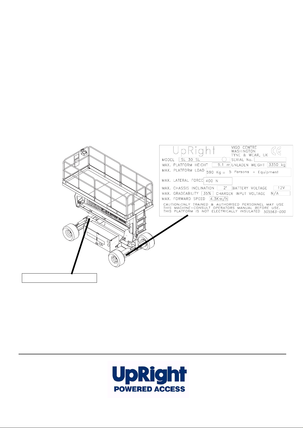
When contacting UpRight for service or parts information, be sure to include the MODEL and SERIAL NUMBERS from t he
equipment nameplate. Should the namepla te be missing, the SERIAL NUMBER is also stamped on top of the chassis
above the front axle pivot.
Stamped Serial Number
USA
TEXT FOR ILLUSTRATION PURPOSE ONLY
Europe
TEL: +1 (559) 443 6600
FAX: +1 (559) 268 2433
TEL: +44 (0) 1952 200
FAX: +44 (0) 1952 229
www.upright.com
Page 4

Page 5
OPERATION MANUAL
C
WARNING
All personnel shall carefully read, understand and follow all safety rules and operating
instructions before operating or performing maintenance on any UpRight aerial work platform.
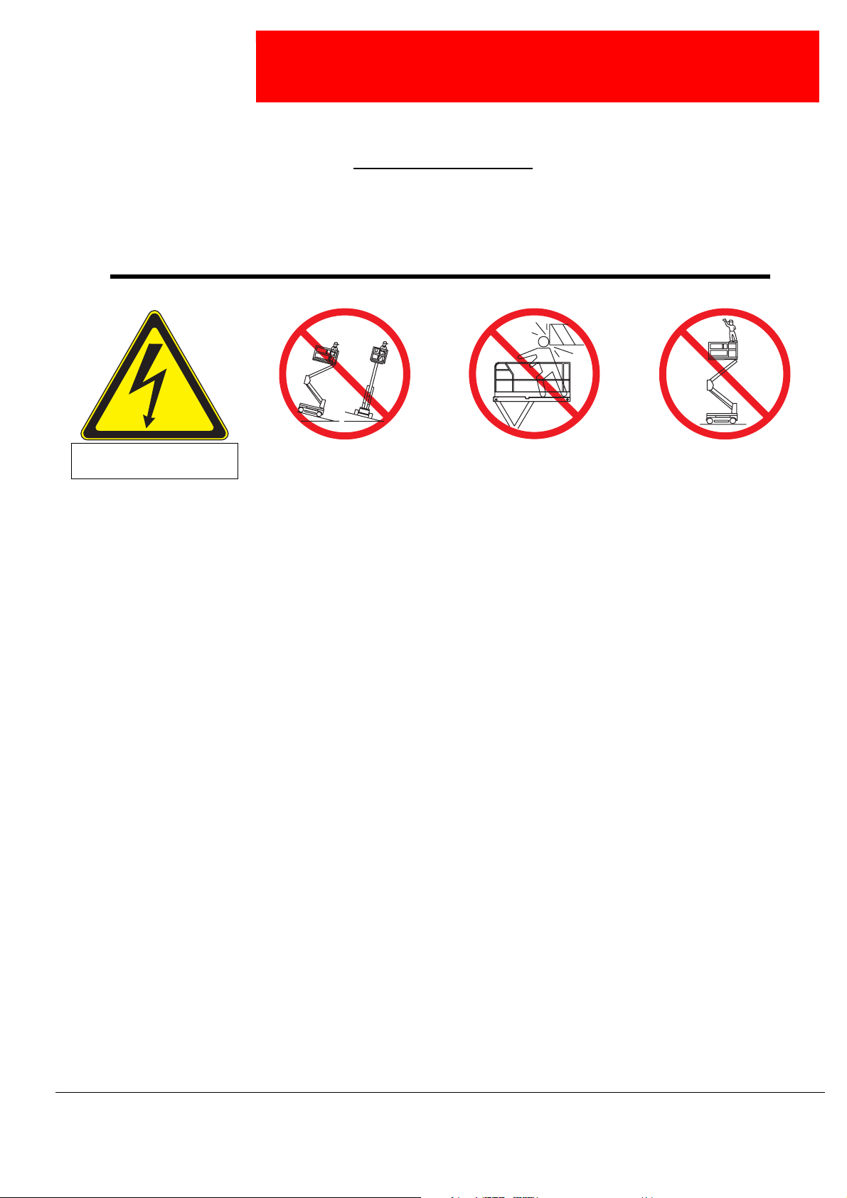
Safety Rules
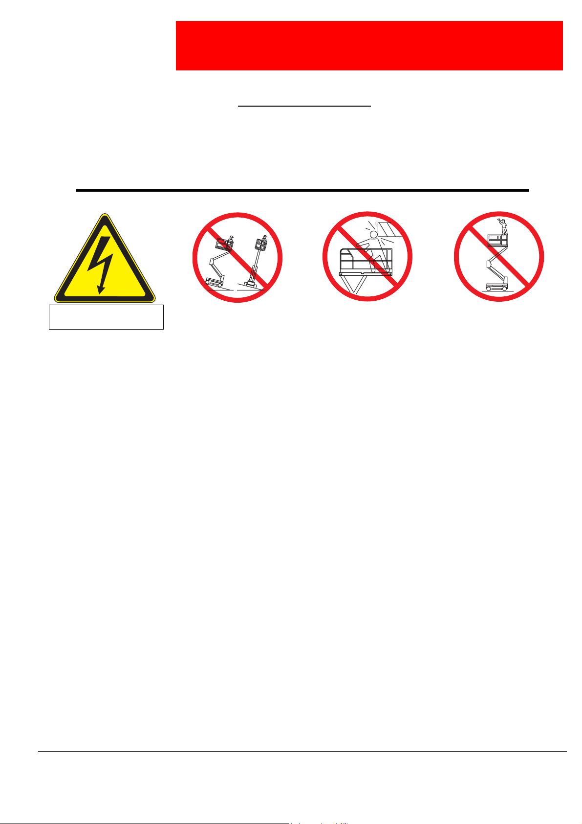
Electrocution Hazard Tip Over Hazard
THIS MACHINE IS NOT
INSULATED!
USE OF THE AERIAL WORK PLATFORM: This aerial work platform is intended to lift persons and his tools as well as the material
used for the job. It is designed for repair and assemb ly jobs and assignments at overhead workplaces (ceilings, cranes, roof structures,
buildings etc.). All other uses of the aerial work platform are prohibited!
THIS AERIAL WORK PLATFORM IS NOT INSULATED! For this reason it is imperative to keep a safe distance from live parts of electrical equipment!
Exceeding the specified permissible maximum load is prohibited! See “Special Limitations” on page 4 for details.
The use and operation of the aerial work platform as a lifting tool or a crane (lifting of loads from below upwards or from up high on
down) is prohibited!
NEVER exceed the manual force allowed for this machine. See “Special Limitations” on page 4 for details.
DISTRIBUTE all platform loads evenly on the platform.
NEVER operate the machine without first surveying the work area for surface hazards such as holes, drop-offs, bumps, curbs, or debris;
and avoiding them.
OPERATE machine only on surfaces capable of supporting wheel loads.
NEVER operate the machine when wind speeds exceed this machine’s wind rating. See “Beaufort Scale” on page 4 for details.
IN CASE OF EMERGENCY push EMERGENCY STOP switch to deactivate all powered functions.
IF ALARM SOUNDS while platform is elevated, STOP, carefully lower platform. Move machine to a firm, level surface.
Climbing up the railing of the platform, standing on or stepping from the platform onto buildings, steel or prefab concrete structures, etc.,
is prohibited!
Dismantling the swing gate or other railing components is prohibited! Always make certain that the swing gate is closed and securely
locked!
It is prohibited to keep the swing gate in an open position (held open with tie-straps) when the platform is raised!
To extend the height or the range by placing of ladders, scaffolds or similar devices on the platform is prohib ited!
NEVER perform service on machine while platform is elevated without blocking elevating assembly.
INSPECT the machine thoroughly for cracked welds, loose or missing hardware, hydraulic leaks, loose wire connections, and damaged
cables or hoses before using.
VERIFY that all labels are in place and legible before using.
NEVER use a machine that is damaged, not functioning properly, or has damaged or missing labels.
To by pa ss any safety equipmen t is prohibited and presents a danger for the persons on the aerial work platform and in its working
range.
NEVER charge batteries near sparks or open flame. Charging batteries emit explosive hydrogen gas.
Modifications to the aerial work platform are prohibited or permissible only at the approval by
AFTER USE, secure the work platform from unauthorized use by turning both keyswitches off and removing key.
NEVER elevate the platform or drive
the machine while elevated unless the
machine is on a firm, level surface.
ollision Hazard Fall Hazard
NEVER position the platform
without first checking for overhead
obstructions or other hazards.
UpRight.
NEVER climb, stand, or sit on
platform guardrails or midrail.
Page 1
Page 6

C
ONTENTS
Introduction. . . . . . . . . . . . . . . . . . . . . . . . . . . . . . . . . . . . . . . . . . . . . . . . . . . . . . . . . . . . . . . . . . . . . . . . . .3
General Description . . . . . . . . . . . . . . . . . . . . . . . . . . . . . . . . . . . . . . . . . . . . . . . . . . . . . . . . . . . . . . . . . . .3
Special Limitations. . . . . . . . . . . . . . . . . . . . . . . . . . . . . . . . . . . . . . . . . . . . . . . . . . . . . . . . . . . . . . . . . . . .4
Platform Capacity . . . . . . . . . . . . . . . . . . . . . . . . . . . . . . . . . . . . . . . . . . . . . . . . . . . . . . . . . . . . . . . . . . . . . . . . . . . 4
Manual Force . . . . . . . . . . . . . . . . . . . . . . . . . . . . . . . . . . . . . . . . . . . . . . . . . . . . . . . . . . . . . . . . . . . . . . . . . . . . . . 4
Beaufort Scale. . . . . . . . . . . . . . . . . . . . . . . . . . . . . . . . . . . . . . . . . . . . . . . . . . . . . . . . . . . . . . . . . . . . . . . . . . . . . . 4
Lift Overload Alarm . . . . . . . . . . . . . . . . . . . . . . . . . . . . . . . . . . . . . . . . . . . . . . . . . . . . . . . . . . . . . . . . . . . . . . . . . . 4
Controls and Indicators . . . . . . . . . . . . . . . . . . . . . . . . . . . . . . . . . . . . . . . . . . . . . . . . . . . . . . . . . . . . . . . .5
Pre-Operation Safety Inspection . . . . . . . . . . . . . . . . . . . . . . . . . . . . . . . . . . . . . . . . . . . . . . . . . . . . . . . . .6
System Function Inspection . . . . . . . . . . . . . . . . . . . . . . . . . . . . . . . . . . . . . . . . . . . . . . . . . . . . . . . . . . . .7
Operation. . . . . . . . . . . . . . . . . . . . . . . . . . . . . . . . . . . . . . . . . . . . . . . . . . . . . . . . . . . . . . . . . . . . . . . . . . . .8
Platform Extension . . . . . . . . . . . . . . . . . . . . . . . . . . . . . . . . . . . . . . . . . . . . . . . . . . . . . . . . . . . . . . . . . . . . . . . . . . 8
Travel With the Platform Lowered. . . . . . . . . . . . . . . . . . . . . . . . . . . . . . . . . . . . . . . . . . . . . . . . . . . . . . . . . . . . . . . 8
Steering. . . . . . . . . . . . . . . . . . . . . . . . . . . . . . . . . . . . . . . . . . . . . . . . . . . . . . . . . . . . . . . . . . . . . . . . . . . . . . . . . . . 8
Elevating the Platform. . . . . . . . . . . . . . . . . . . . . . . . . . . . . . . . . . . . . . . . . . . . . . . . . . . . . . . . . . . . . . . . . . . . . . . . 8
Travel With the Platform Elevated. . . . . . . . . . . . . . . . . . . . . . . . . . . . . . . . . . . . . . . . . . . . . . . . . . . . . . . . . . . . . . . 9
Lowering the Platform . . . . . . . . . . . . . . . . . . . . . . . . . . . . . . . . . . . . . . . . . . . . . . . . . . . . . . . . . . . . . . . . . . . . . . . . 9
Levelling the Platform . . . . . . . . . . . . . . . . . . . . . . . . . . . . . . . . . . . . . . . . . . . . . . . . . . . . . . . . . . . . . . . . . . . . . . . . 9
Emergency Lowering. . . . . . . . . . . . . . . . . . . . . . . . . . . . . . . . . . . . . . . . . . . . . . . . . . . . . . . . . . . . . . . . . . . . . . . . 10
Fold Down guardrails, . . . . . . . . . . . . . . . . . . . . . . . . . . . . . . . . . . . . . . . . . . . . . . . . . . . . . . . . . . . . . . . . . . . . . . . 11
Fold Down Procedure . . . . . . . . . . . . . . . . . . . . . . . . . . . . . . . . . . . . . . . . . . . . . . . . . . . . . . . . . . . . . . . . . . . 11
Erection Procedure . . . . . . . . . . . . . . . . . . . . . . . . . . . . . . . . . . . . . . . . . . . . . . . . . . . . . . . . . . . . . . . . . . . . . 11
Towing or Winching . . . . . . . . . . . . . . . . . . . . . . . . . . . . . . . . . . . . . . . . . . . . . . . . . . . . . . . . . . . . . . . . . .12
Parking Brake Release . . . . . . . . . . . . . . . . . . . . . . . . . . . . . . . . . . . . . . . . . . . . . . . . . . . . . . . . . . . . . . . . . . . . . . 12
After Use Each Day. . . . . . . . . . . . . . . . . . . . . . . . . . . . . . . . . . . . . . . . . . . . . . . . . . . . . . . . . . . . . . . . . . . . . . . . . 12
Hour Meter . . . . . . . . . . . . . . . . . . . . . . . . . . . . . . . . . . . . . . . . . . . . . . . . . . . . . . . . . . . . . . . . . . . . . . . . . . . . . . . 12
Transporting the Work Platform . . . . . . . . . . . . . . . . . . . . . . . . . . . . . . . . . . . . . . . . . . . . . . . . . . . . . . . .13
Preparation for Shipment . . . . . . . . . . . . . . . . . . . . . . . . . . . . . . . . . . . . . . . . . . . . . . . . . . . . . . . . . . . . . . . . . . . . 13
Lifting By Crane. . . . . . . . . . . . . . . . . . . . . . . . . . . . . . . . . . . . . . . . . . . . . . . . . . . . . . . . . . . . . . . . . . . . . . . . . . . . 13
By Forklift . . . . . . . . . . . . . . . . . . . . . . . . . . . . . . . . . . . . . . . . . . . . . . . . . . . . . . . . . . . . . . . . . . . . . . . . . . . . . . . . 13
Driving or Winching onto a Truck or Trailer. . . . . . . . . . . . . . . . . . . . . . . . . . . . . . . . . . . . . . . . . . . . . . . . . . . . . . . 13
Maintenance . . . . . . . . . . . . . . . . . . . . . . . . . . . . . . . . . . . . . . . . . . . . . . . . . . . . . . . . . . . . . . . . . . . . . . . .14
Blocking The Elevating Assembly. . . . . . . . . . . . . . . . . . . . . . . . . . . . . . . . . . . . . . . . . . . . . . . . . . . . . . . . . . . . . . 14
Scissor Brace Installation . . . . . . . . . . . . . . . . . . . . . . . . . . . . . . . . . . . . . . . . . . . . . . . . . . . . . . . . . . . . . . . . . 14
Scissor Brace Stowage . . . . . . . . . . . . . . . . . . . . . . . . . . . . . . . . . . . . . . . . . . . . . . . . . . . . . . . . . . . . . . . . . . 14
Battery Maintenance . . . . . . . . . . . . . . . . . . . . . . . . . . . . . . . . . . . . . . . . . . . . . . . . . . . . . . . . . . . . . . . . . . . . . . . . 15
Battery Charging . . . . . . . . . . . . . . . . . . . . . . . . . . . . . . . . . . . . . . . . . . . . . . . . . . . . . . . . . . . . . . . . . . . . . . . 15
Fault Codes . . . . . . . . . . . . . . . . . . . . . . . . . . . . . . . . . . . . . . . . . . . . . . . . . . . . . . . . . . . . . . . . . . . . . . . . . . . 16
Inspection and Maintenance Schedule . . . . . . . . . . . . . . . . . . . . . . . . . . . . . . . . . . . . . . . . . . . . . . . . . . . . . . .17
Daily Preventative Maintenance Checklist. . . . . . . . . . . . . . . . . . . . . . . . . . . . . . . . . . . . . . . . . . . . . . . .17
Specifications . . . . . . . . . . . . . . . . . . . . . . . . . . . . . . . . . . . . . . . . . . . . . . . . . . . . . . . . . . . . . . . . . . . . . . .18
Page 2 Operation Manual
Page 7

Introduction
I
NTRODUCTION
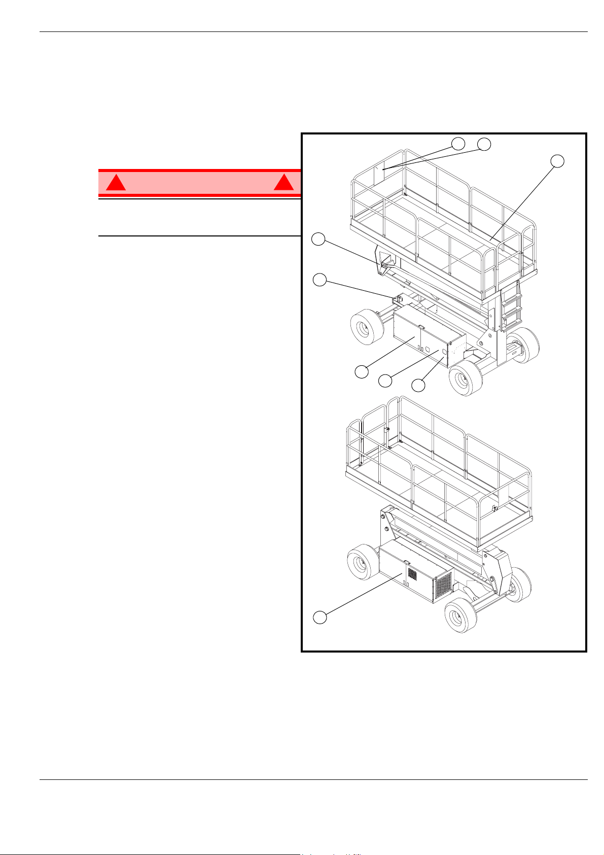
This manual covers operation of the SL26 & SL26/30 Speed Level Series Self-Propelled Work Platforms.
This manual must be stored on the machine at all times.
G
ENERAL
1. Platform
D
ESCRIPTION
Figure 1: SL26/30 SL Series
7
6
1
!
WARNING
DO NOT use the maintenance platform
without guardrails properly assembled
and in place
2. Elevating Assembly
3. Chassis
4. Power Module
5. Control Module
6. Platform Controls
7. Manual Case
8. Chassis Controls
9. Hydraulic Fluid Reservoir
!
2
3
5
8
9
4
Operation Manual Page 3
Page 8
Special Limitations
S
PECIAL
P
M
L
IMITATIONS
Travel with the platform raised is limited to creep speed range.
Elevating the Work Platform is limited to firm, level surfaces only.
DANGER
! !
The elevating function shall ONLY be used when the work platform is leveled and on a firm surface.
The work platform is NOT intended to be driven over uneven, rough, or soft terrain.
LATFORM
The maximum capacity for the MACHINE, including occupants is determined by model and options, and
is listed in “Specifications” on page 18.
DANGER
! !
DO NOT exceed the maximum platform capacity or the platform occupancy limits for this machine.
ANUAL
Manual force is t he force applied by the occu pants to objects such a s w alls or o ther structures out side the
work platform.
F
C
APACITY
ORCE
The maximum allowable manual f orce is limited to 200 N ( 45 lbs.) of force per occupa nt , wit h a maximum
of 400 N (90 lbs.) for two or more occupants.
DANGER
! !
DO NOT exceed the maximum amount of manual force for this machine.
B
EAUFORT
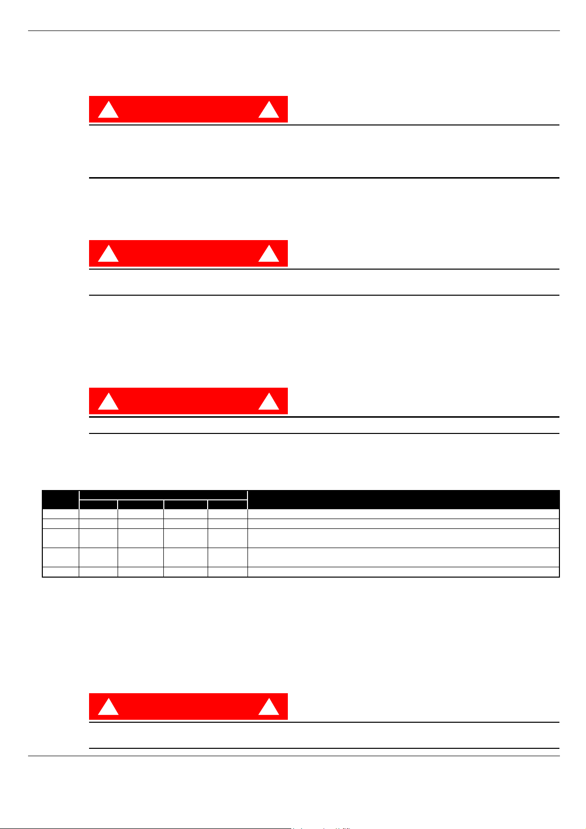
Never operate the machine when wind speeds exceed 12.5m/s (28 mph) [Beaufort scale 6].
BEAUFORT
RATING
3 3,4~5,4 12,25~19,4 11.5~17.75 7.5~12.0 Papers and thin branches move, flags wave.
4 5,4~8,0 19,4~28,8 17.75~26.25 12.0~18 Dust is raised, paper whirls up, and small branches sway.
5 8,0~10,8 28,8~38,9 26.25~35.5 18~24.25 Shrubs with leaves start swaying. Wave crests are apparent in ponds or swamps.
6 10,8~13,9 38,9~50,0 35.5~45.5 24.5~31 Tree branches move. Power lines whistle. It is difficult to open an umbrella.
7 13,9~17,2 50,0~61,9 45.5~56.5 31.~38.5 Whole trees sway. It is difficult to walk against the wind.
m/s km/h ft/s mph
L
IFT
O
If a load equivelent to 90% of safe working load is lifted a fault code “03” will be displayed on the digital
display on the platform control box. If a load which is greater than the safe working load is present in the
basket all machine functions will cease to operate and an acoustic warning will sound. In order to return to
normal operation a load equal to or less than the saf e working load m ust be present in th e bask et and th e
power must be re-cycled, power can be re-cycled by pushing the emergency stop button and releasing it
again.
WIND SPEED
VER L OA D
S
CALE
A
LARM
GROUND CONDITIONS
DANGER
! !
Never operate the machine with a platform load greater than the rated capacity.
Page 4 Operation Manual
Page 9
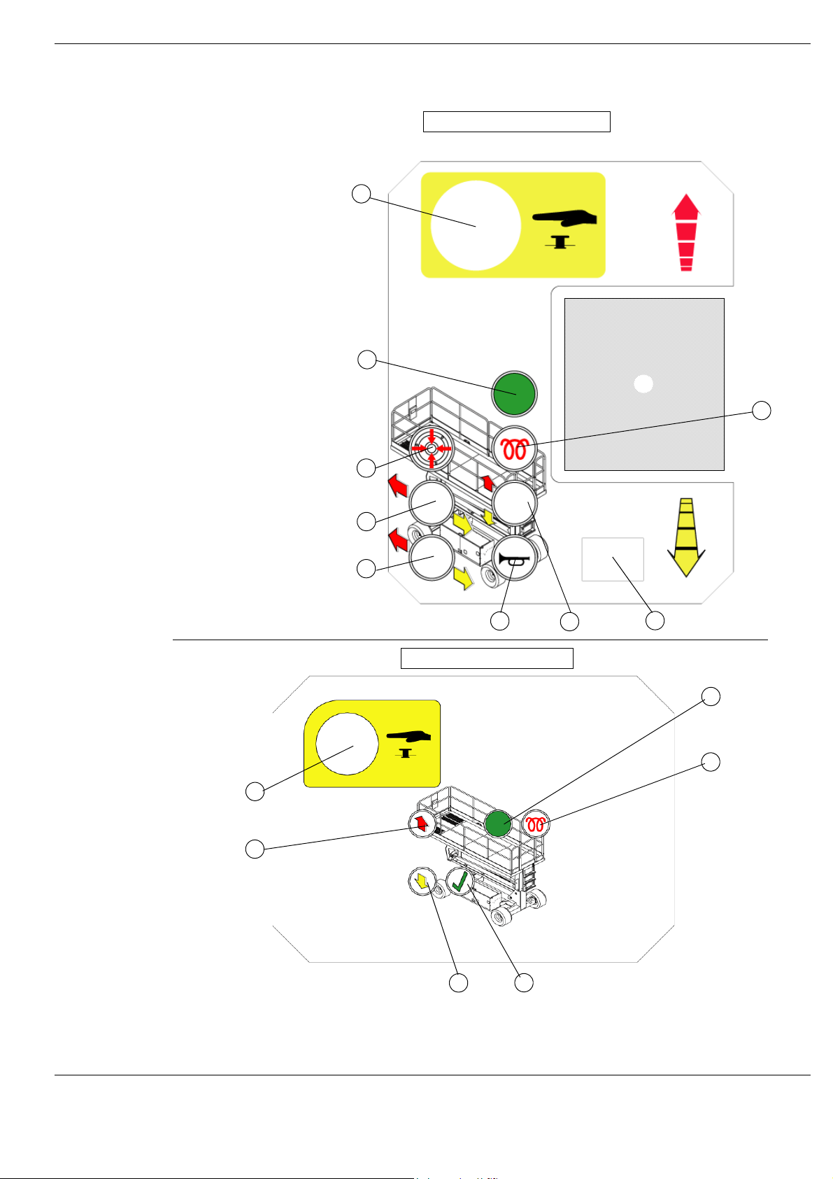
Controls and Indicators
C
ONTROLS
AND
I
NDICATORS
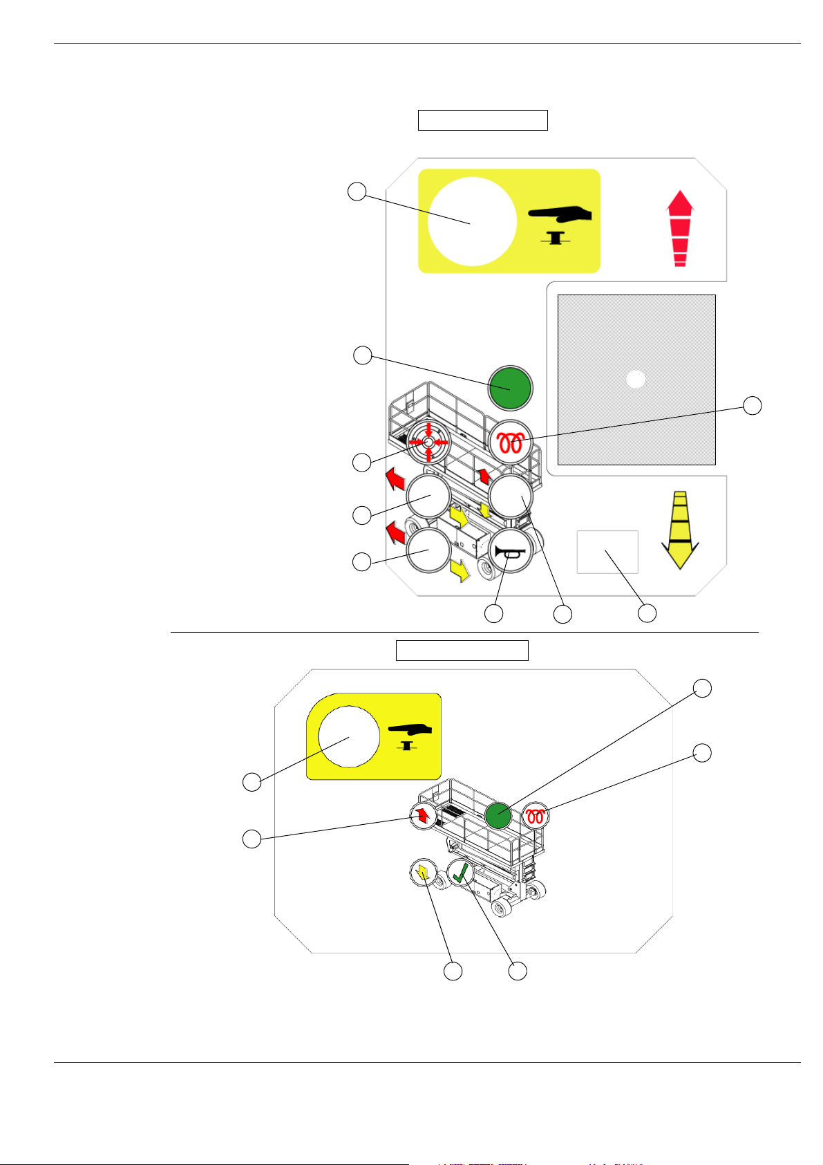
Figure 2: Controls and Indicators
Platform Controls
8
7
10
6
1 Drive (Hi Speed)
2. Drive (Low Speed)
3. Level
4. Horn Button
5. Lift/Lower Button
6. Glow Plug
7. Engine Start
8. Emergency Stop Button
9. Display
10. Joystick
1
2
3
2
1
4
Chassis Controls
5
9
6
5
1. Emergency Stop
2. Elevate
3. Descend
4. Enable
5. Glow Plug
6. Start
3
4
Operation Manual Page 5
Page 10
Pre-Operation Safety Inspection
P
RE
-O
PERATION
NOTE: Carefully read, understand and follow all safety rules, operating instructions, labels and
National Safety Instructions/Requirements. Perform the following steps each day before use.
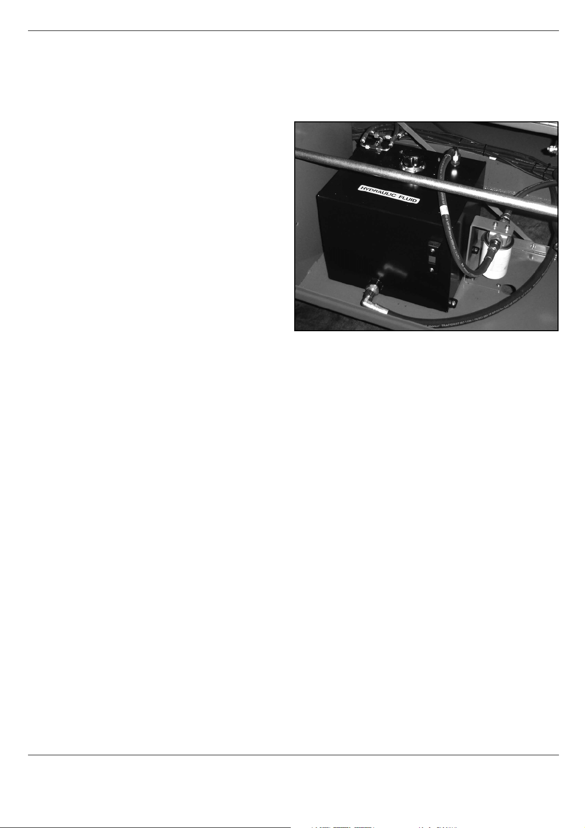
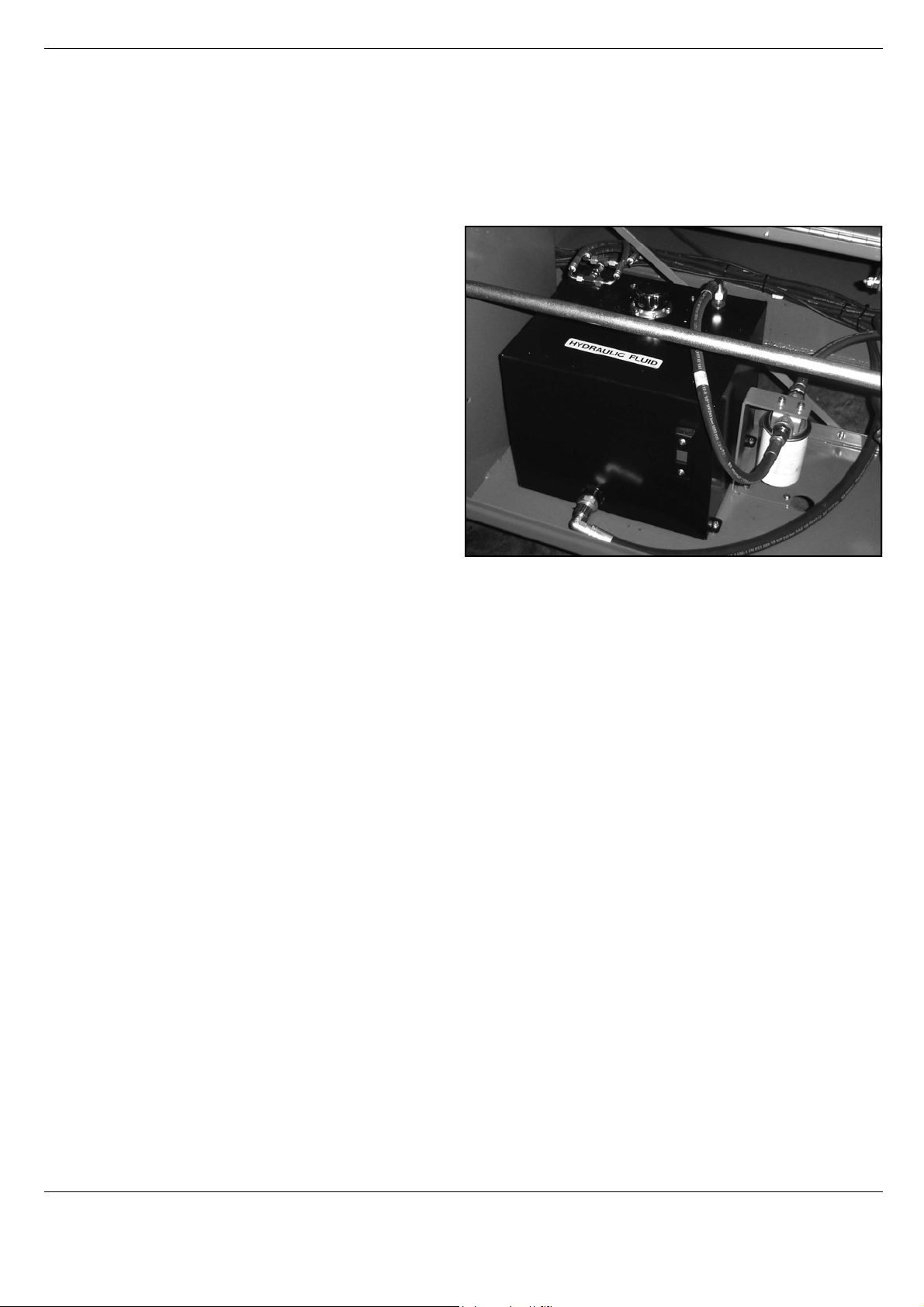
1. Open modules and inspect for damage, fluid leaks or missing parts.
2. Check the leve l of the h ydraulic fluid with
the platform fully lowered. The hydraulic
reservoir is located in the Control Module Door. The fluid level must be
between the MIN and MAX lines. Add
hydraulic fluid if necessary.
3. Check that fluid level in the starter battery is correct.
4. Check the level of the Diesel fuel with
the engine switched off. The fuel tank is
located in the Power Module. Add fuel
as required.
5. Check that all guardrails are in place
and all fasteners are properly tightened.
6. Inspect the machine thoroughly for
cracked w elds and structural damage,
loose or missing hardware, hydraulic
leaks, damaged control cable, loose wire connections and wheel bolts.
S
AFETY
I
NSPECTION
Figure 3: Hydraulic Tank
Page 6 Operation Manual
Page 11

System Function Inspection
S
YSTEM
F
UNCTION
Refer to Figure 2 (Page 5) for the locations of various controls and indicators.
I
NSPECTION
!
WARNING
STAND CLEAR of the work platform while performing the following checks.
Before operating the work platform, survey the work area for surface hazards such as holes, drop-offs,
bumps and debris.
Check in ALL directions, including above the work platform, for obstructions and electrical cond u cto rs.
Protect the control console cable from possible damage while performing checks.
1. Move the machine, if necessary, to an unobstructed area to allow for full elevation.
2. Twist Chassis Emergency Stop Switch to the ON position.
3. Twist Platform Emergency Stop Switch t o the ON position.
4. Turn the Key Switch to the ON position.
5. Visually inspect the elevating assembly, lift cylinder, cables, and hoses for cracked welds and structural
damage, loose hardware, hydraulic leaks, loose wire connections, and erratic operation. Check for missing or loose parts.
6. Push the Chassis ELEVATE and ENABLE buttons and fully elevate the platform.
7. Partially lower the platform by pushing Chassis DESCEND and ENABLE buttons, and check for proper
operation of the audible lowering alarm.
8. Open the Emergency Lowering Valve (see Figure 4) by pulling the knob out to check for proper operation. When the platform is lowered, release the knob.
9. Push the Chassis Emergency Stop Switch to check for proper operation. All machine functions should
be disabled. Twist the Chassis Emergency Stop Switch to resume.
10. Check that the route is clear of obstacles (persons, obstructions, holes, and drop-offs, bumps and
debris), is level, and is capable of supporting the wheel loads.
11. Mount the platform and properly close the entrance.
12. Select DRIVE mode.
!
NOTE: Use both HI and LOW drive (if applicable) when performing the following step.
13. While engaging the Safety Interlock Trigger, move the Joystick to FORWARD, then REVERSE, to check
for speed control.
14. Push the Steering Switch RIGHT, then LEFT, to check for steering control.
15. Select LIFT mode. Grasp the Joystick, engaging the Safety Interlock Trigger, and push it forward to
check platform lift controls. Raise the platform to full elevation.
16. Pull back on the Joystick. The platform should descend and the audible lowering alarm should sound.
17. Push the Platform Emergency Stop Switch to check for proper operation. All machine functions should
be disabled. Pull out the Platform Emergency Stop Switch to resume.
Operation Manual Page 7
Page 12

Operation
O
PERATION
Before operating t he wo rk platform, ensure that the Pre-Operation Saf et y Inspecti on has been co mpleted
and that any deficiencies ha v e been cor rected. Ne ver opera te a dama ged or malfunctioning mac hine.
The operator must be thoroughly trained on this machine.
S
TARTING THE
1. Mount the platform and properly close the entrance.
2. Depress and hold the GLOW PLUG button for approximately 5 seconds.
3. Press green START button.
T
RAVEL
1. Check that the route is clear of obstacles (persons, obstructions, holes, drop-offs, bumps, and debris),
is level, and is capable of supporting the wheel loads.
2. Verify that the Engine is started and the Chassis Emergency Stop Switch is ON (pulled out).
3. Mount the platform and properly close the entrance.
4. Check clearances above, below, and to the sides of platform.
5. Twist the Platform Emergency Stop Switch out to the ON position.
6. Select DRIVE mode.
W
ITH THE
E
NGINE
P
LATFORM
L
OWERED
NOTE: Choose between standard drive and extra torque depending on the gradient.
7. Engage the Safety Interlock Trigger and move the Joystick to FORWARD or REVERSE to travel in the
desired direction. The speed of the machine will vary depending on how far from center the Joystick is
moved.
S
TEERING
1. Turn the Drive/Lift Switch to DRIVE.
2. While engaging the Safety Interlock Trigger, push the Steering Switch to RIGHT or LEFT to turn the
wheels in the desired direction. Observe the tires while maneuvering the work platform to ensure proper
direction.
NOTE: Steering is not self-centering. Wheels must be returned to the straight ahead position by
operating the Steering Switch.
E
LEVATING
1. Select a firm, level surface.
2. Select LIFT mode.
3. While engaging the Safety Interlock Trigger, push the Joystick forward.
4. If the machine is not level the tilt alarm will sound and the machine will not lift or drive.
5. If the tilt alarm sounds the platform must first be fully lowered, then elevate the platform approximately
600mm (2ft), stop, press and hold the LEVEL button until the tilt alarm is silenc ed . On ly then ca n you
elevate fully. If the platform is not levelled correctly the tilt alarm will continue to sound and lift functions
will be cut at a height of approximately 2m (6ft).
THE
P
LATFORM
Page 8 Operation Manual
Page 13

Operation
T
RAVEL
NOTE: The machine will travel at reduced speed when the platform is elevated.
1. Check that the route is clear of obstacles (persons , obstructions , holes , drop-offs , b umps, and debris), is
level, and is capable of supporting the wheel loads.
2. Check clearances above, below, and to the sides of platform.
3. Select DRIVE mode.
4. Engage the Safety Interlock Trigger on the Joystick and move to FORWARD or REVERSE to travel in
the desired direction. The speed of the machine will vary depending on how far from center the Jo ystick
is moved.
5. If the machine is not level the tilt alarm will sound and the machine will not lift or drive. If the tilt alarm
sounds the platform must be lowered and the machine moved to a firm, level surface before attempting
to re-elevate the platform.
L
OWER ING THE
1. Select LIFT mode.
2. Check around the base of the platform to ensure that no one is in contact wit h the machine. Engage the
Safety Interlock Trigger and pull back on the Joystick to lower the platform.
3. The platform will stop when it reaches the PPE cutout height. Inspect around the machine to ensure no
one is in contact with the machine. After a four-second time delay, lower the platform as in step 2.
W
ITH THE
P
P
LATFORM
LATFORM
E
LEVATED
L
EVELLING
The AUTO LEVEL feature is designed to level the platform in a situation where the ground has no more
than a 13 degree slope side to side and 9 degr ees f o re and aft , if the slop e is gr eater than 1 3 degr ees side
to side and 9 degrees fore and aft the AUTO LEVEL feature will not function.
The tilt alarm will continue to sound until the platform is level
1. Check that the route is clear of obstacles (persons , obstructions , holes , drop-offs , b umps, and debris), is
level, and is capable of supporting the wheel loads.
2. Check clearances above, below, and to the sides of platform.
3. Elevate the platform approximately 600mm (2ft).
4. Press and hold the AUTO LEVEL and Engage the Safety Interlock Trigger until the platform is level and
the tilt alarm is silenced.
5. In this condition only the ELEVATE and DESCEND functions will work.
6. If you need to drive you must descend and return the platform to it’s normal inclanation.
THE
P
LATFORM
Operation Manual Page 9
Page 14
Operation
E
MERGENCY
L
OWER ING
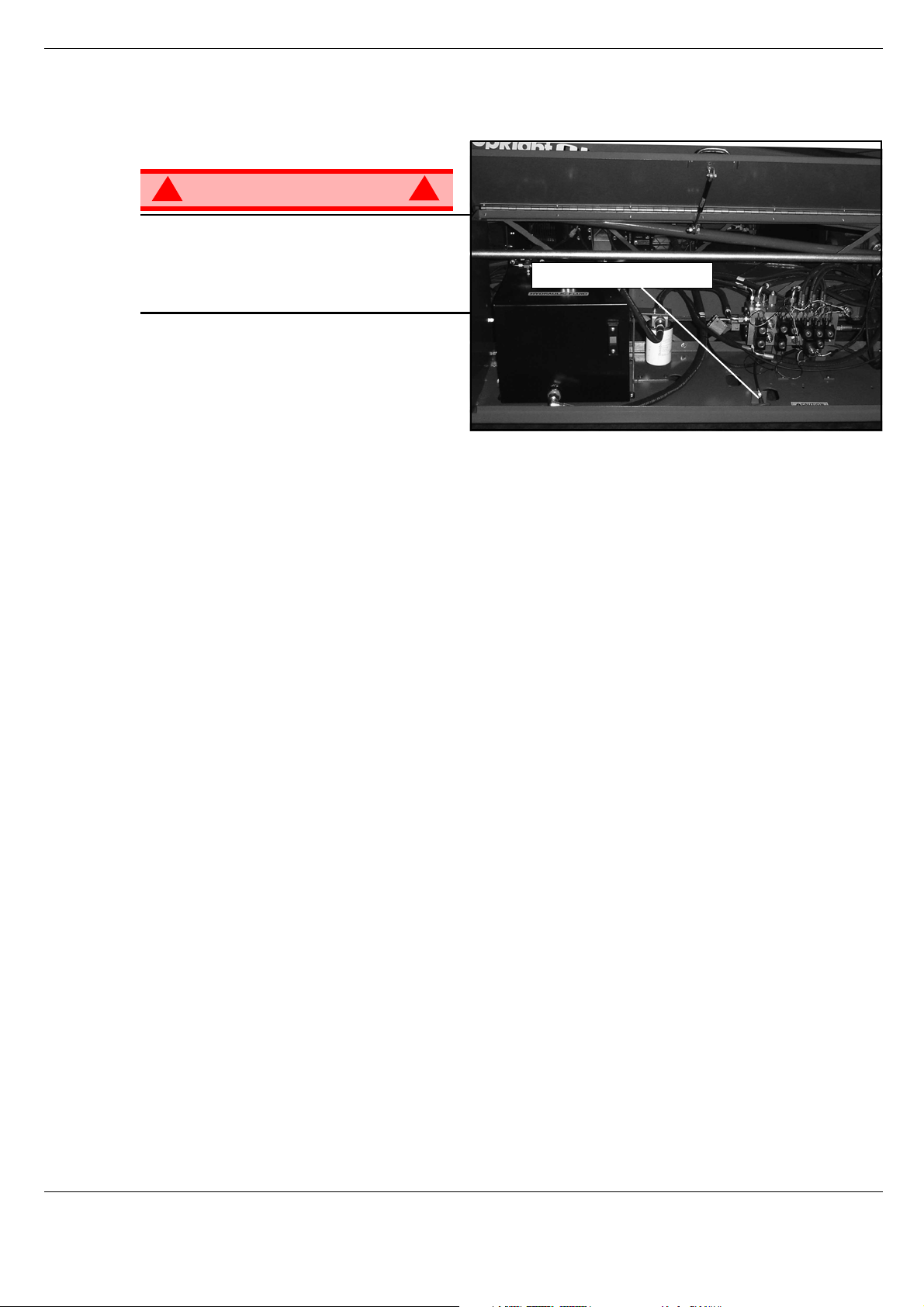
Figure 4: Emergency Lowering Valve
!
WARNING
If the platform should fail to lower, NEVER
climb down the elevating assembly.
Stand clear of the elevating assembly while
operating the Emergency Lowering Valve
Knob.
SL26-30 S
The Emergency Lowering Valve for the
SL26-30 is located in the control module of
the machine and is accessable through an
opening in the control module door.
1. Open the Emergency Lowering Valve by pulling and holding the handle.
2. To close, release the knob. The platform will not elev ate if the Emergency Lowering Valve is open.
PEED
L
EVEL
!
Emergency Lowering Knob
Page 10 Operation Manual
Page 15

Operation
F
OLD
This procedure applies only to the SL26-30 Speed Level model for the purpose of passing through a standard double doorway. Guardrails must be returned to proper position before using the machine.
F
OLD
1. Unhook the controller from the side guardrail and place it on the floor of the platform.
2. Starting at the front of the platform, remove nuts, bolts and washers from the top of the front guardrail.
Fold the front guardrail down onto the platform.
3. Close and latch gate.
4. Remove nuts, bolts and washers from the top of the rear guardrail. Fold the rear guardrail do wn onto the
platform being careful to keep latched at all times.
5. Remove nuts, bolts and w ashers from the to p of the side guardr ails. Li ft up and f old one sid e guardrail in
E
RECTION PROCEDURE
D
OWN GUARDRAILS
D
OWN PROCEDURE
so it rests on the deck. Repeat with other side guardrails.
1. Raise side guardrails, making sure each is pushed down to secure the guardrail in the vertical
position.
2. Install bolts, washers and nuts betw een the side guardrails, tighten securely.
3. Raise rear guardrail assembly, aligning holes and install bolts, washers and nuts. Tighten securely.
DANGER
! !
Before entering platform, guardrails
must be securely fastened in their
proper position.
Operation Manual Page 11
Page 16
Towing or Winching
T
OWIN G OR
Perform the following only when the machine will not operate under its own power and it is necessary to
move the machine or when winching onto a transport vehicle (see “Transporting the Work Platform” on
page 13).
W
INCHING
CAUTION
DO NOT tow or winch the machine faster than 0,3 m/s (1 ft./s). Faster speeds will damage drive
components and void the warranty.
B
RAKE
Perform the following only when the machine will not operate under it’s own power and it is necessary to move the machine or when towing the machine up a grade or onto a trailer to transport.
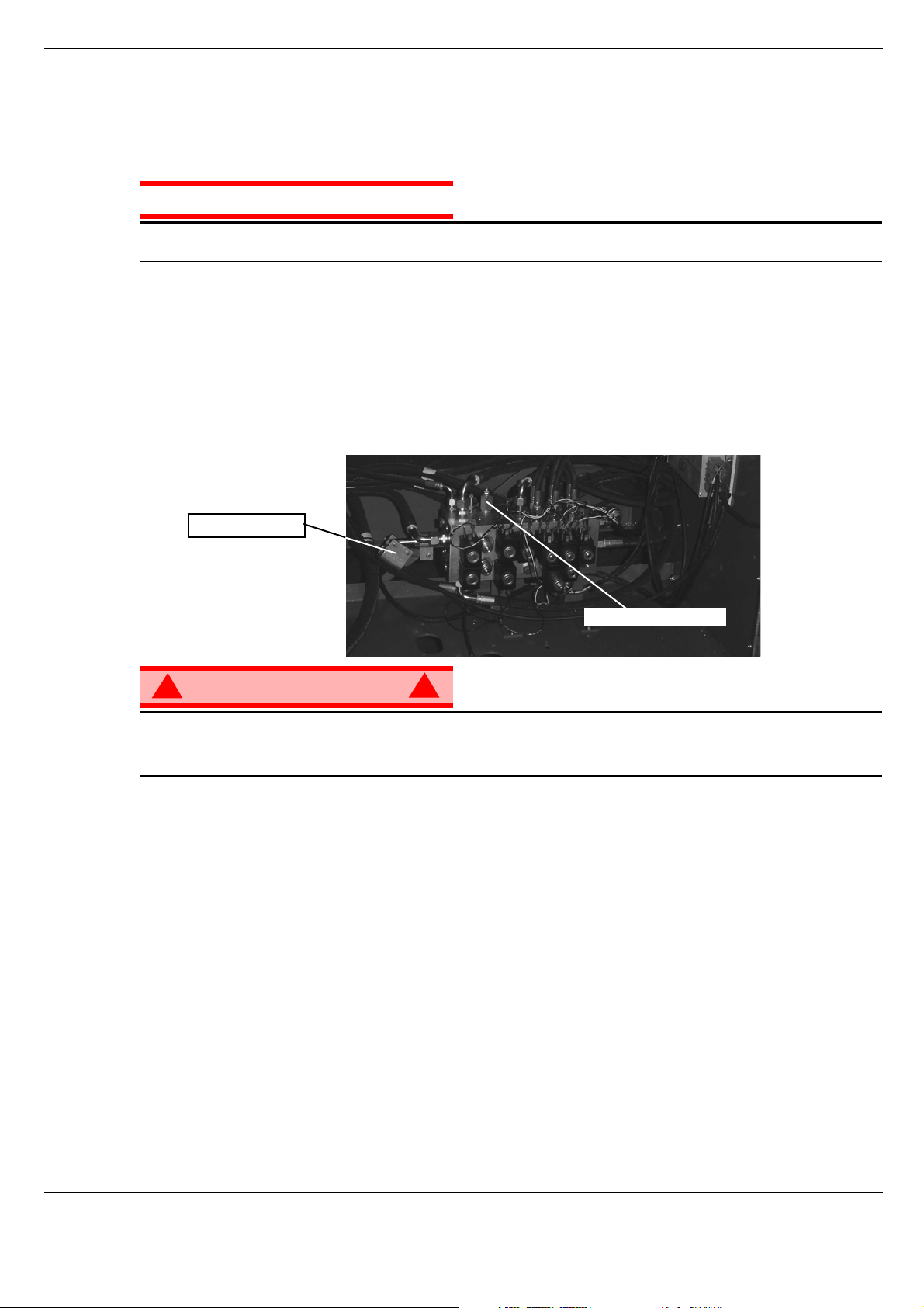
1. Close the needle valve by turning the allen screw clockwise.
2. Pump the Brake Release Pump until the Parking Brake Cylinder Rod clears the wheel rotor.
3. The machine will now roll when pushed or pulled.
4. Be sure to open needle valve and verify that the cylinder rod has extended before the machine
is operated.
R
ELEASE
P
UMP
Hand Pump
Needle Valve
!
WARNING
Never tow faster than 0,3 m/sec. (1 ft./sec.).
Never op erate the work platform with the parking brakes released. Serious injury or damage could
result.
A
FTER
1. Ensure that the platform is fully lowered.
2. Park the machine on a firm level surface, preferably under cover, secure against vandals, children and
unauthorized operation.
3. Turn the Chassis Key Switch to OFF and remove the key to prevent unauthorized ope ration.
H
OUR
To access the hour meter function perform the following steps.
U
M
SE
ETER
E
ACH
!
D
AY
1. Climb into the basket (with the machine powered up)
2. Push the platform emergency stop button.
3. Hold down the following buttons, Horn & Lift.
4. While holding the buttons twist the emergency stop button to return power to the machine.
5. “hr” will now be displayed on the readout, Pressing the right turn button will scroll through the accumulated hours two digits at a time. For example, if pressing the right turn butto n once displays “20”, pressing
it a 2nd time displays “58”, and pressing it a 3rd time displays “hr”, the elapsed time of operation is 2058
hours.
Page 12 Operation Manual
Page 17

Transporting the Work Platform
T
RANSPORTING
P
REPARATION FOR
1. Fully lower the platform.
2. Disconnect the battery negative (-) lead from the battery terminal.
3. Band the controller to the front guardrail.
4. Band the elevating linkage to the frame.
L
IFTING
1. Secure straps to chassis tie down/lifting lugs only.
2. Place the platform onto the transport vehicle in transport position.
3. Chock the wheels.
4. Secure the work platform to the transport vehicle with chains or straps of adequate load capacity
attached to the chassis tie down/lifting lugs.
B
Y
THE
C
W
RANE
ORK
S
HIPMENT
P
LATFORM
BY F
! !
Forklifting is for transport only.
See specifications for weight of work platform and be certain that forklift is of adequate capacity to lift
the work platform.
Forklift from the side by lifting under the Chassis Modules.
D
RIVING OR
ONTO
RAILER
T
NOTE: Do not winch faster than 0,3 m/s (1 ft/s).
1. Move the machine onto the truck or trailer;
A. To Drive the machine onto the transport vehicle:
B. To Winch the machine onto the transport vehicle:
2. Secure the work platform to the transport vehicle with chains or straps of adequate load capacity
ORKLIFT
DANGER
W
INCHING
A T
a. Move the work platform up the ramp and into
transport position.
b. Set the wheels straight and turn off the machine.
c. Chock the wheels.
a. Move the work platform up to the ramp.
b. Attach the winch cable to the tie down/lifting lugs.
c. Release the parking brakes (refer to “Towing or
Winching” on page 12).
d. Winch the platform into transport position
e. Chock the wheels.
attached to the chassis tie down/lifting lugs.
RUCK OR
Front Tie
Down and
Lifting Lugs
Figure 5: Transporting the Work Platform
Forklift
Rear Tie Down/Lift
CAUTION
Overtightening of the chains or straps attached to the Tie Down/Lifting Lugs may result in damage to
work platform.
Operation Manual Page 13
Page 18
Maintenance
M
AINTENANCE
!
WARNING
Never pe rform service while the platform is elevated without first blocking the elevating assembly.
DO NOT stand in the elevating assembly area while deploying or storing the brace.
B
LOCKING
LEVATING
E
T
HE
A
SSEMBLY
!
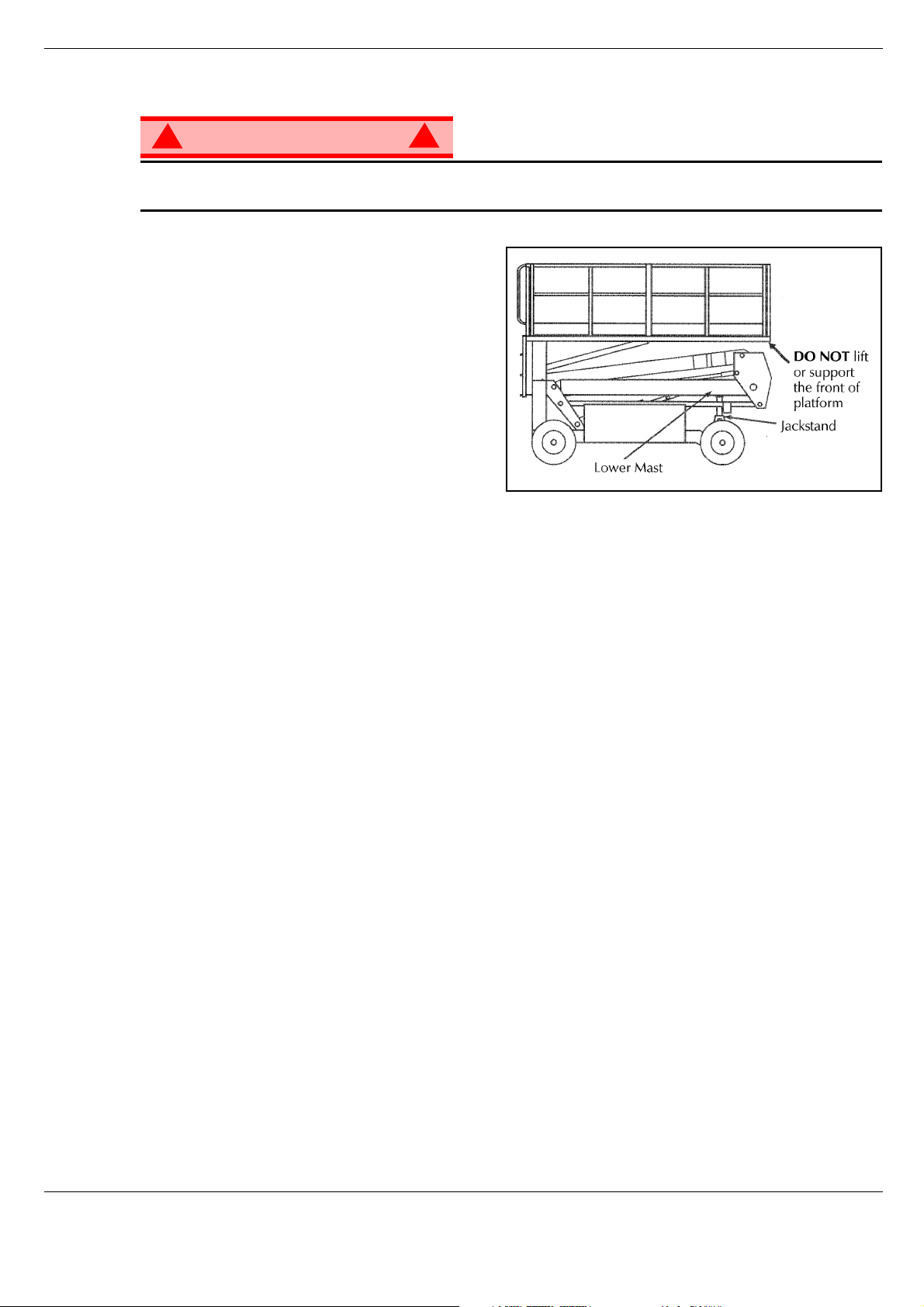
Figure 6: Scissor Brace
INSTALLATION
1. P ark the work platform on firm, level ground and
leave the engine running.
2. Ensure the Chassis Emergency Stop Button is
twisted to the ON position.
3. Press and hold the Chassis LIFT and ENABLE
buttons to elevate the platform approximately
305 mm (12 inches).
4. Place a jackstand with a minimum rating of
1814 kg (4000 lbs.) betw een the lower ma st and
chassis, just behind the front axle.
5. Press and hold the Chassis DESCEND and ENABLE buttons to lower the platform until jackstand is
secured tightly between lower mast and Chassis.
REMOVAL
1. Press and hold the Chassis LIFT and ENABLE buttons to elevate the platform until the jackstand can
be removed.
2. Remove jackstand.
3. Press and hold the Chassis DESCEND and ENABLE buttons to completely lower the platform.
Page 14 Operation Manual
Page 19

Maintenance
B
ATTERY
M
AINTENANCE
!
WARNING
Hazard of explosive gas mixture. Keep sparks, flame, and smoking material away from batteries.
Always wear safety glasses when working near batteries.
Battery fluid is highly corrosive. Thoroughly rinse away any spilled fluid with clean water.
Always replace batteries with UpRight batteries or manufacturer approved replacements.
• Check the battery fluid level daily, especially if the work platform is being used in a warm, dry climate.
• If electrolyte level is lower than 10 mm
tap water with high mineral content, as it will shorten battery life.
• Keep the terminals and tops of the batteries clean.
• Refer to the Service Manual to extend battery life and for complete service instructions.
B
ATTERY CHARGING
The battery is charged while the engine is running.
!
3
(
/
in.) above the plates add distilled water only. DO NOT use
8
Operation Manual Page 15
Page 20

Maintenance
F
AULT
01 - SYSTEM INIT ERROR
02 - SYSTEM PLATFORM COM ERROR
03 - PLATFORM OVERLOAD
04 - SYSTEM LOWER PANEL COM ERROR
05 - OIL PRESSURE LOW
06 - COOLANT TEMP HOT
21 - PLATFORM START ON
22 - PLATFORM LEFT TURN SW ON
23 - PLATFORM RIGHT TURN SW ON
24 - PLATFORM LIFT SW ON
25 - PLATFORM HISPEEDDRIVE SW ON
26 - PLATFORM GLOWLP SW ON
27 - PLATFORM LOSPEEDDRIVE SW ON
28 - PLATFORM AUTOLEVEL SW ON
29 - PLATFORM JOYSTICK ENABLE SW ON
C
ODES
31 - PLATFORM JOYSTICK NOT NEUTRAL
34 - GROUND PANEL ENABLE SW ON
37 - GROUND PANEL DOWN SW ON
38 - GROUND PANEL UP SW ON
43 - GROUND PANEL START SW ON
45 - GROUND PANEL GLOWLP SW ON
51 - Coil Fault HiSpeed1
52 - Coil Fault HiSpeed2
55 - Coil Fault LiftUp
56 - Coil Fault LiftDown
57 - Coil Fault TiltLeft
58 - Coil Fault TiltRight
59 - Coil Fault SteerRight
61 - Coil Fault SteerLeft
62 - Coil Fault TiltRear
63 - Coil Fault TiltForward
66 - Coil Fault Forward
67 - Coil Fault Reverse
71 - Coil Fault CushionValve
72 - Coil Fault AxleFloat
73 - Coil Fault SteerDump
68 – LOW BATTERY FAULT
Page 16 Operation Manual
Page 21
Inspection and Maintenance Schedule
I
NSPECTION
The Complete Inspection consists of periodic visual and operational checks, along with periodic minor
adjustments that assure proper performance. Daily inspection will prevent abnormal wear and prolong the
life of all systems. The inspection and maintenance schedule should be performed at the specified intervals. Inspection and maintenance shall be performed by personnel who are trained and familiar with
mechanical and electrical proc edu re s.
AND
M
AINTENANCE
S
CHEDULE
D
AILY
M
AINTENANCE
Y = Yes/Acceptable
N = No/Not Acceptable
R = Repaired/Acceptable
!
WARNING
Before performing preventative maintenance, familiarize yourself with the operation of the machine.
Always block the elevating assembly whenever it is necessary to perform maintenance while the
platform is elevated.
The daily preventative maintenance checklist has been designed for machine service and maintenance.
Please photocopy this page and use the checklist when inspecting the machine.
P
REVENTATIVE
T
ABLE KEY
!
M
AINTENANCE
P
Date:_______________________________________
Owner: _____________________________________
Model No:___________________________________
Serial No: ___________________________________
REVENTATIVE
C
M
AINTENANCE
HECKLIST
R
EPORT
COMPONENT INSPECTION OR SERVICES Y N R
Battery
Chassis
Control Cable
Controller Check switch operation.
Drive Motors Check for operation and leaks.
Elevating
Assembly
Emergency
Lowering System
Entire Unit Check for and repair collision damage.
Check electrolyte level.
Check battery cable condition.
Check hoses for pinch or rubbing points.
Check welds for cracks.
Check the exterior of the cable for pinching,
binding or wear.
Inspect for structural cracks.
Operate the emergency lowering valve and check
for serviceability.
Serviced By:_________________________________
COMPONENT INSPECTION OR SERVICES Y N R
Hydraulic Fluid Check fluid level.
Hydraulic Pump Check for hose fitting leaks.
Hydraulic System Check for leaks.
Labels
Platform Deck
and Rails
Platform Deck
and Rails
Tires and Wheels Check for damage.
Check for peeling, missing, or unreadable labels
& replace.
Check welds for cracks.
Check condition of deck.
Operation Manual Page 17
Page 22

505562-000 Specifications
S
PECIFICATIONS
ITEM SL26SL SL30SL
Platform Size (Inside Toeboards)
Standard 1,71 m x 4,22 m [67.5 in. x 166.5 in.] 1,71 m x 4,22 m [67.5 in. x 166.5 in.]
Slide Out Deck Extended 1,71 m x 4,61 m [67.5 in. x 181.5 in.] N/A
Max. Platform Capacity
Standard 680kg [1,500 lbs.] 590 kg [1,300 lbs.]
w/ Extension 680kg [1,500 lbs.] N/A
On Extension 227g [500 lbs.] N/A
Max. No. of occupants
Standard 5 people 5 people
on Extension 2 people N/A
Height
Working Height 9.75 m [32 ft.] 10.97 m [36 ft.]
Max. Platform Height 7.93m [26 ft.] 9,14 m [30 ft.]
Min. Platform Height 1.5 m [59 in.] 1.5 m [59 in.]
Max. Drive Height 7.93 m [26 ft.] 9.14 m [30 ft.]
Dimensions
Weight Diesel: 3,216 kg [7,090 lbs.] Diesel: 3.216 kg [7,090 lbs.]
Overall Width, Standard 2,13 m [84 in.] 2,13 m [84 in.]
Overall Height 2,6 m [102.5 in.] 2,6 m [102.5 in.]
Overall Length, Standard 3.79 m [149 in.] 4,39 m [173 in.]
Surface Speed
Platform Lowered 0 to 5.0 km/h [0 to 3.1 m.p.h.] 0 to 5.0 km/h [0 to 3.1 m.p.h.]
Platform Raised 0 to 0.8 km/h [0 to 0.5 m.p.h.] 0 to 0.8 km/h [0 to 0.5 m.p.h.]
System Voltage 12 Volt DC 12 Volt DC
Hydraulic Tank Capacity 74 l [19.5 US Gallons] 74 l [19.5 US Gallons]
Maximum Hydraulic System Pressure 210 bar [3000 psi] 210 bar [3000 psi]
Hydraulic Fluid
Above 32° f [0° c]) ISO #46 ISO #46
Normal use, below 32° f [0° c]) ISO #32 ISO #32
Below 0° f [-17° c] ISO #15 ISO #15
Lift System One Single Stage Lift Cylinders One Single Stage Lift Cylinders
Lift Speed Raise, 48 sec./Lower, 40 sec. Raise, 48 sec./Lower, 40 sec.
Platform Leveling 13° side to side, 9° Fore and Aft 13° side to side, 9° Fore and Aft
Power Source 20 HP (Diesel) 20 HP (Diesel)
Drive Control Proportional Proportional
Control System Joystick Controller with Safety
Interlock Trigger and Thumb Rocker
Steering, Toggle Selector and
Emergency Stop Switches
Horizontal Drive Four Wheel, Hydraulic Motors Four Wheel, Hydraulic Motors
Tyres (Standard) 26 x 12.00 - 12 NHs Super Terra-grip
with Trac Seal
ANSI Spec. Pneumatic Tire Pressure Do Not Exceed 57 PSI Do Not Exceed 57 PSI
Parking Brakes Dual Spring Applied, Hydraulic
Release, multi-disc
Turning Radius (inside) 3,96 m [13 ft.] 3,96 m [13 ft.]
Maximum Gradeability 35% [19°] 35% [19°]
Wheel Base 2,54 m [100 in.] 2,54 m [100 in.]
Guardrails 1,11 m [43.5 in.] high, Fold Down with
gate.
Toe board 152 mm [6 in.] High 152 mm [6 in.] High
Joystick Controller with Safety
Interlock Trigger and Thumb Rocker
Steering, Toggle Selector and
Emergency Stop Switches
26 x 12.00 - 12 NHs Super Terra-grip
with Trac Seal
Dual Spring Applied, Hydraulic
Release, multi-disc
1,11 m [43.5 in.] high, Fold Down with
gate.
*Specifications are subject to change without no tice. Hot weather or he avy use may affect performance.
Refer to the Service Manual for complete parts and service information.
This machine meets or exceeds all applicable requirements of OSHA and ANSI A92.6-1999.
Page 18 Operation Manual
Page 23

Serie SL26/30SL
Seriennummern 50001 – aktuell
DEUTSCH
Stellen Sie sicher , dass Sie die MODEL L- und SERIENNUMMERN auf dem G erätetype nschild angeben, w enn Sie sich mit
UpRight bezüglich Wartungs- oder Ersatzteilinformationen in Verbindung setzen. Sollte das Typenschild fehlen, finden Sie
die SERIENNUMMER auch auf dem Fahrwerk über der vorderen Schwenkachse.
Eingestanzte Seriennummer
USA
TEL: +1 (559) 443 6600
FAX: +1 (559) 268 2433
Europa
TEL: +44 (0) 1952 200
FAX: +44 (0) 1952 229
www.upright.com
Page 24

Page 25
BETRIEBSANLEITUNG
S
WARNUNG
Alle Bediener müssen die Sicherheitsregeln und Betriebsanleitungen gründlich durchlesen,
verstehen und befolgen, bevor sie an irgendeiner UpRight-Hocharbeitsbühne Wartungsarbeiten
ausführen oder die Arbeitsbühne in Betrieb nehmen.
Sicherheitsregeln
Elektroschockgefahr Kippgefahr Kollisionsgefahr
DIESE MASCHINE IST NICHT
ISOLIERT!
EINSATZ DER HOCHARBEITSBÜHNE: Diese Hocharbeitsbühne dient dazu, Personen und Werkzeuge sowie die für die j eweilige Arbeit
erforderlichen Materialien zu transportieren. Sie wurde speziell für Reparatur- und Montagearbei ten sowie für Einsatzbereiche konzipiert, die
sich oberhalb der Mitarbeiter befinden, sodass die Mitarbeiter nach oben gerichtet arbeiten müssen (z. B. Decken, Kräne, Dachstrukturen,
Gebäude etc.). Jede andere Verwendung der Hocharbeitsbühne ist strikt verboten!
DIESE HOCHARBEITSBÜHNE IST NICHT ISOLIERT! Aus diesem Grund muss zwingend ein Sicherheitsabstand zu allen leitfähigen Teilen
der elektrischen Ausrüstung eingehalten werden!
Die angegebene zulässige Höchstlast darf nicht überschritten werden! Nähere Informationen hierzu finden Sie im Abschnitt
“Beschränkungen” auf Seite 4.
Es ist streng verboten, die Hocharbeitsbüh ne als Hubwerkzeug oder Kran einzusetzen (d. h. um Lasten von unten nach oben oder von oben
nach unten zu befördern).
Die für diese Maschine zuläss i ge m anuelle Kraft NIEMALS überschreiten. Nähere Informationen hierzu finden Sie im Abschnitt
“Beschränkungen” auf Seite 4.
Lasten immer gleichmäßig auf der Plattform VERTEILEN.
Vor Inbetriebnahme der Maschine IMMER ZUERST die Aufstellfläche im Arbeitsbereich auf Gefahren wie Bodenlöcher, ausgelaufene
Flüssigkeiten, Bodenerhebungen, Kanten oder Schutt untersuchen und diese umgehen bzw. beseitigen.
Maschine nur auf Oberflächen IN BETRIEB NEHMEN, die die zulässigen Radlasten aufnehmen können.
Maschine NIEMALS in Betrieb nehmen, wenn di e tatsächliche Windgeschwindigkeit höher ist als die Windgeschwindigkeit, für die die
Maschine ausgelegt ist. Nähere Informationen hierzu finden Sie im Abschnitt “Beaufort-Skala” auf Seite 4.
IM NOTFALL NOT-AUS-Schalter drücken, um alle strombetriebenen Funktionen zu deaktivieren.
WENN EIN ALARM ERTÖNT, während die Plattform ausgefahren wird, Plattform ANHALTEN und vorsichtig einfahren (absenken). Maschine
auf feste, ebene Oberfläche fahren.
Es ist verboten, auf das Schutzgeländer der Plattform zu klettern, darauf zu stehen oder von der Plattform aus auf Gebäude, Stahl- oder
vorgefertigten Betonstrukturen zu zu klettern!
Das Schwingtor oder andere Komponenten des Schutzgeländers zu demontieren ist verboten! Vergewissern Sie sich immer, dass das
Schwingtor geschlossen und sicher verriegelt ist!
Es ist verboten, das Schwingtor geöffnet zu halten (z. B. mit Befestigungsgurten), wenn die Plattform ausgefahre n wird!
Die Höhe oder Reichweite der Plattform durch Anbringen von Leitern, Gerüsten oder ähnlichen Vorrichtungen zu vergrößern ist verboten!
IMMER ZUERST die Hubvorrichtung blockieren, bevor bei ausgefahrener Plattform Wartungs- oder Instandhaltungsarbeiten an der Maschine
durchgeführt werden.
Maschine vor jedem Gebrauch sorgfältig auf Risse an Schweißstellen, lose oder fehlende Beschläge, Leckagen in der Hydraulikvorrichtung,
gelöste Kabelverbindungen und beschädigte Kabel oder Schläuche UNTERSUCHEN.
Vor Gebrauch SICHERSTELLEN, dass alle Bezeichnungsschilder ordnungsgemäß angebracht und vollständig lesbar sind.
NIEMALS eine Maschine benutzen, die beschädigt ist, nicht ordnungsgemäß funktioniert oder deren Bezeichnungsschilder Beschädigungen
aufweisen oder sogar ganz fe hlen.
Sicherheitseinrichtungen zu umgehen ist verboten und stellt eine Gef ahr für alle Personen dar, die sich auf der Hocharbeit sbühne und in deren
Arbeitsbereich befinden.
Batterien NIEMALS in der Nähe von Funkenquellen oder offenen Flammen aufladen. Beim Aufladen von Batterien wird explosives
Wasserstoffgas freigesetzt.
Änderungen an der Hocharbeitsbühne sind verboten bzw. nur mit ausdrücklicher Zustimmung von UpRight zulässig.
NACH GEBRAUCH ist die Hocharbeit sb ühne gegen unbefug ten Gebr auch du rch Dritte zu s ichern. Hierzu müs sen beide Schlü sselschalt er auf
“Aus” gestellt und die Schlüssel abgezogen werden.
NIEMALS die Plattform ausfahren oder die
Maschine mit ausgefahrener Plattform
fortbewegen, wenn sich die Maschine nicht
auf einer festen, ebenen Fläche befindet.
Plattform NIEMALS in Position bringen,
ohne vorher sicherzustellen, dass der
Bereich über der Plattform frei von
Hindernissen und anderen Gefahren ist.
Plattformgeländers klettern und au ch
turzgefahr
NIEMALS auf das obere oder
mittlere Gestänge des
nicht darauf stehen oder sitzen.
Seite 1
Page 26

I
NHALT
Einführung. . . . . . . . . . . . . . . . . . . . . . . . . . . . . . . . . . . . . . . . . . . . . . . . . . . . . . . . . . . . . . . . . . . . . . . . . . .3
Allgemeine Beschreibung . . . . . . . . . . . . . . . . . . . . . . . . . . . . . . . . . . . . . . . . . . . . . . . . . . . . . . . . . . . . . .3
Beschränkungen . . . . . . . . . . . . . . . . . . . . . . . . . . . . . . . . . . . . . . . . . . . . . . . . . . . . . . . . . . . . . . . . . . . . .4
Tragfähigkeit der Plattform . . . . . . . . . . . . . . . . . . . . . . . . . . . . . . . . . . . . . . . . . . . . . . . . . . . . . . . . . . . . . . . . . . . . .4
Manuelle Kraft . . . . . . . . . . . . . . . . . . . . . . . . . . . . . . . . . . . . . . . . . . . . . . . . . . . . . . . . . . . . . . . . . . . . . . . . . . . . . .4
Beaufort-Skala . . . . . . . . . . . . . . . . . . . . . . . . . . . . . . . . . . . . . . . . . . . . . . . . . . . . . . . . . . . . . . . . . . . . . . . . . . . . . .4
Überlastalarm . . . . . . . . . . . . . . . . . . . . . . . . . . . . . . . . . . . . . . . . . . . . . . . . . . . . . . . . . . . . . . . . . . . . . . . . . . . . . . .4
Bedienelemente und Anzeigen . . . . . . . . . . . . . . . . . . . . . . . . . . . . . . . . . . . . . . . . . . . . . . . . . . . . . . . . . .5
Sicherheitsprüfung vor Inbetriebnahme . . . . . . . . . . . . . . . . . . . . . . . . . . . . . . . . . . . . . . . . . . . . . . . . . .6
Überprüfung der Systemfunktionen . . . . . . . . . . . . . . . . . . . . . . . . . . . . . . . . . . . . . . . . . . . . . . . . . . . . .7
Bedienung . . . . . . . . . . . . . . . . . . . . . . . . . . . . . . . . . . . . . . . . . . . . . . . . . . . . . . . . . . . . . . . . . . . . . . . . . . .8
Starten des Motors . . . . . . . . . . . . . . . . . . . . . . . . . . . . . . . . . . . . . . . . . . . . . . . . . . . . . . . . . . . . . . . . . . . . . . . . . . 8
Fahren mit eingefahrener Plattform. . . . . . . . . . . . . . . . . . . . . . . . . . . . . . . . . . . . . . . . . . . . . . . . . . . . . . . . . . . . . . 8
Lenken. . . . . . . . . . . . . . . . . . . . . . . . . . . . . . . . . . . . . . . . . . . . . . . . . . . . . . . . . . . . . . . . . . . . . . . . . . . . . . . . . . . . 8
Ausfahren der Plattform . . . . . . . . . . . . . . . . . . . . . . . . . . . . . . . . . . . . . . . . . . . . . . . . . . . . . . . . . . . . . . . . . . . . . . .8
Fahren mit ausgefahrener Plattform . . . . . . . . . . . . . . . . . . . . . . . . . . . . . . . . . . . . . . . . . . . . . . . . . . . . . . . . . . . . . 9
Einfahren der Plattform . . . . . . . . . . . . . . . . . . . . . . . . . . . . . . . . . . . . . . . . . . . . . . . . . . . . . . . . . . . . . . . . . . . . . . .9
Nivellieren der Plattform . . . . . . . . . . . . . . . . . . . . . . . . . . . . . . . . . . . . . . . . . . . . . . . . . . . . . . . . . . . . . . . . . . . . . . 9
Notfallabsenkung . . . . . . . . . . . . . . . . . . . . . . . . . . . . . . . . . . . . . . . . . . . . . . . . . . . . . . . . . . . . . . . . . . . . . . . . . . .10
Einklappen des Schutzgeländers . . . . . . . . . . . . . . . . . . . . . . . . . . . . . . . . . . . . . . . . . . . . . . . . . . . . . . . . . . . . . . .11
Einklappen . . . . . . . . . . . . . . . . . . . . . . . . . . . . . . . . . . . . . . . . . . . . . . . . . . . . . . . . . . . . . . . . . . . . . . . . . . . . 11
Ausklappen . . . . . . . . . . . . . . . . . . . . . . . . . . . . . . . . . . . . . . . . . . . . . . . . . . . . . . . . . . . . . . . . . . . . . . . . . . . 11
Schleppen oder Anheben . . . . . . . . . . . . . . . . . . . . . . . . . . . . . . . . . . . . . . . . . . . . . . . . . . . . . . . . . . . . .12
Manuelles Lösen der Feststellbremsen. . . . . . . . . . . . . . . . . . . . . . . . . . . . . . . . . . . . . . . . . . . . . . . . . . . . . . . . . . 12
Nach dem täglichen Gebrauch . . . . . . . . . . . . . . . . . . . . . . . . . . . . . . . . . . . . . . . . . . . . . . . . . . . . . . . . . . . . . . . . .12
Betriebsstundenzähler . . . . . . . . . . . . . . . . . . . . . . . . . . . . . . . . . . . . . . . . . . . . . . . . . . . . . . . . . . . . . . . . . . . . . . . 12
Transport der Arbeitsbühne . . . . . . . . . . . . . . . . . . . . . . . . . . . . . . . . . . . . . . . . . . . . . . . . . . . . . . . . . . .13
Vorbereitung . . . . . . . . . . . . . . . . . . . . . . . . . . . . . . . . . . . . . . . . . . . . . . . . . . . . . . . . . . . . . . . . . . . . . . . . . . . . . . 13
Anheben per Kran. . . . . . . . . . . . . . . . . . . . . . . . . . . . . . . . . . . . . . . . . . . . . . . . . . . . . . . . . . . . . . . . . . . . . . . . . . 13
Per Gabelstapler . . . . . . . . . . . . . . . . . . . . . . . . . . . . . . . . . . . . . . . . . . . . . . . . . . . . . . . . . . . . . . . . . . . . . . . . . . .13
Fahren oder Heben auf einen LKW oder Anhänger . . . . . . . . . . . . . . . . . . . . . . . . . . . . . . . . . . . . . . . . . . . . . . . . 13
Instandhaltung . . . . . . . . . . . . . . . . . . . . . . . . . . . . . . . . . . . . . . . . . . . . . . . . . . . . . . . . . . . . . . . . . . . . . .14
Blockieren der Hubvorrichtung . . . . . . . . . . . . . . . . . . . . . . . . . . . . . . . . . . . . . . . . . . . . . . . . . . . . . . . . . . . . . . . . 14
Installation der Hubvorrichtung . . . . . . . . . . . . . . . . . . . . . . . . . . . . . . . . . . . . . . . . . . . . . . . . . . . . . . . . . . . . 14
Entfernung der Hubvorrichtung . . . . . . . . . . . . . . . . . . . . . . . . . . . . . . . . . . . . . . . . . . . . . . . . . . . . . . . . . . . . 14
Instandhaltung der Batterie . . . . . . . . . . . . . . . . . . . . . . . . . . . . . . . . . . . . . . . . . . . . . . . . . . . . . . . . . . . . . . . . . . .15
Aufladen der Batterie . . . . . . . . . . . . . . . . . . . . . . . . . . . . . . . . . . . . . . . . . . . . . . . . . . . . . . . . . . . . . . . . . . . .15
Fehlercodes . . . . . . . . . . . . . . . . . . . . . . . . . . . . . . . . . . . . . . . . . . . . . . . . . . . . . . . . . . . . . . . . . . . . . . . . . . . 16
Inspektions- und Instandhaltungsplan . . . . . . . . . . . . . . . . . . . . . . . . . . . . . . . . . . . . . . . . . . . . . . . . . . . . . . . .17
Checkliste der täglichen präventiven Instandhaltungsmaßnahmen . . . . . . . . . . . . . . . . . . . . . . . . . .17
Technische Daten. . . . . . . . . . . . . . . . . . . . . . . . . . . . . . . . . . . . . . . . . . . . . . . . . . . . . . . . . . . . . . . . . . . .18
Seite 2 Betriebsanleitung
Page 27
Einführung
E
INFÜHRUNG
Dieses Handbuch beschreibt Einsatz und Bedienung der selbstfahrenden Arbeitsbühnen der Serie
SL26/30 Speed Level. Das Handbuch muss immer bei der Maschine aufbewahrt werden.
A
LLGEMEINE
1. Plattform
B
ESCHREIBUNG
Figure 1: Serie SL26/30 SL
7
6
1
!
WARNUNG
Hocharbeitsbühne NICHT ohne korrekt
montiertes und angebrachtes
Schutzgeländer verwenden.
2. Hubvorrichtung
3. Fahrwerk
4. Antriebsmodul
5. Steuermodul
6. Plattform-Bedienelemente
7. Handbuchfach
8. Fahrwerk-Bedienelemente
9. Behälter für Hydraulikflüssigkeit
!
2
3
5
8
9
4
Betriebsanleitung Seite 3
Page 28
Beschränkungen
B
ESCHRÄNKUNGEN
Bei ausgefahrener Plattform kann die Maschine nur im Schleichgang gefahren werden.
Die Arbeitsbühne kann nur auf festen, ebenen Oberflächen ausgefahren werden.
GEFAHR
! !
Die Hubfunktion darf NUR verwendet werden, wenn die Arbeitsbühne nivelliert ist und auf einer festen
Oberfläche steht.
Die Arbeitsbühne ist NICHT daf ür ausgelegt, auf unebenem, grobem oder w eichem Gelände gef ahren
zu werden.
T
RAGFÄHIGKEIT DER
Die maximale Tragfähigkeit der MASCHINE, einschließlich P ersonen , hängt vom Modell und verschieden en
Optionen ab; Sie finden eine entsprechende Liste im Abschnitt “Technische Daten” auf Seite 18.
GEFAHR
! !
Maximale Tr agfähig keit der Platt form oder maximal zulässige Personenzahl für diese Maschine NICHT
überschreiten.
P
LATTFORM
M
ANUELLE
Unter manueller Kraft versteht man die Kraft, die die Personen auf der Plattform auf Objekte wie Wände
oder andere Strukturen außerhalb der Arbeitsbühne ausüben.
Die maximal zulässige manuelle Kraft ist auf 200 N pro Person beschränkt, d. h. maximal 400 N, wenn
sich zwei oder mehr Personen auf der Plattform befinden.
GEFAHR
! !
Die für diese Maschine maximal zulässige manuelle Kraft NICHT überschreiten.
B
EAUFORT
Niemals die Maschine in Betrieb nehmen, wenn die Windgeschwindigkeit mehr als 12,5 km/h [BeaufortSkala 6] beträgt.
BEAUFORT-
WERT
3 3,4~5,4 12,25~19,4 11,5~17,75 7,5~12,0 Papier und dünne Zweige bewegen sich, Fahnen wehen.
4 5,4~8,0 19,4~28,8 17,75~26,25 12,0~18 Staub und Papier wird aufgewirbelt und kleine Zweige schaukeln.
5 8,0~10,8 28,8~38,9 26,25~35,5 18~24,25
6 10,8~13,9 38,9~50,0 35,5~45,5 24,5~31
7 13,9~17,2 50,0~61,9 45,5~56,5 31~38,5 Ganze Bäume schwanken. Das Gehen bei Gegenwind ist schwierig.
m/s km/h ft/s mph
Ü
WINDGESCHWINDIGKEIT
BERLASTALARM
Wenn eine Last angehoben wird, die 90 % der Nennlast ausmacht, erscheint im digitalen Display des
Bedienpultes an der Plattform der Fehlercode “03”. Befindet sich im Fahrkorb eine Last , die höh er als die
Nennlast ist, werden alle Maschinenfunktionen blockiert und eine akustische Warnung ertönt. Damit der
normale Betrieb wieder aufgenommen werden kann, muss die Last im Fahrkorb verringert werden,
sodass sie gleich oder niedriger als die Nennlast ist, und die Stromzufuhr zur Maschine muss aus- und
wieder eingeschaltet werden. Das Aus- und wieder Einschalten der Stromversorgung kann durch
Drücken und anschließendes Lösen des Not-Aus-Tasters erfolgen.
K
-S
RAFT
KALA
BODEN-/UMGEBUNGSBEDINGUNGEN
Sträucher mit Blättern beginnen zu schaukeln. In Teichen, Sümpfen oder anderen Gewässern erscheinen
Wellenkämme.
Zweige und Äste von Bäumen bewegen sich. Stromleitungen pfeifen. Regenschirme können nur mit Mühe
geöffnet werden.
GEFAHR
! !
Niemals die Maschine in Betrieb nehmen, wenn sich auf der Plattform eine Last befindet, die die
angegebene Tragfähigkeit überschreitet.
Seite 4 Betriebsanleitung
Page 29
Bedienelemente und Anzeigen
B
EDIENELEMENTE
UND
A
NZEIGEN
Plattform-Bedienelemente
Figure 2: Bedienelemente und Anzeigen
8
7
10
6
1 Antrieb (schnell)
2. Antrieb (langsam)
3. Nivellieren
4. Taste für die Hupe
5. Taste zum Aus-/Einfahren
6. Taste für Vorglühen
7. Start des Motors
8. Not-Aus-Taster
9. Display
10. Steuerknüppel
1
2
3
2
1
4
Fahrwerk-Bedienelemente
5
9
6
5
1. Not-Aus
2. Ausfahren
3. Einfahren
4. Freigabe
5. Taste für Vorglühen
6. Start
3
4
Betriebsanleitung Seite 5
Page 30
Sicherheitsprüfung vor Inbetriebnahme
S
ICHERHEITSPRÜFUNG
NOTE: Lesen Sie sich alle Sicherheitsregeln, Betriebsanleitungen, Bezeichnungsschilder und
nationalen Sicherheitsanweisungen/-anforderungen sorgfältig durch, stellen Sie sicher,
dass Sie sie vollständig verstanden haben und halten Sie sie ein. Gehen Sie jeden Tag vor
Inbetriebnahme der Maschine wie folgt vor.
1. Öffnen Sie die Module, und untersuchen Sie sie auf Beschädigungen, Leckagen oder fehlende Teile.
2. Überprüfen Sie bei vollständig
abgesenkter Plattform die
Füllstandshöhe der Hydraulikflüssigkeit.
Der Hydraulikbehälter befindet sich in
der Tür des Steuermoduls. Die
Füllstandshöhe der Flüssigkeit muss
zwischen den Strichen für MIN und MAX
liegen. Füllen Sie bei Bedarf
Hydraulikflüssigkeit nach.
3. Stellen Sie sicher, dass die Flüssigkeit
in der Starterb a tte rie die korrekte
Füllstandshöhe aufweist.
4. Überprüfen Sie bei ausgeschaltetem
Motor die Füllstandshöhe des
Dieselkraftstoffs. Der Kraftstofftank
befindet sich in der Tür des
Antriebsmoduls. Füllen Sie bei Bedarf
Kraftstoff nach.
5. Überprüfen Sie, ob alle Komponenten der Schutzgeländer angebracht und sämtliche
Befestigungselemente ordnungsgemäß festgezogen sind.
6. Untersuchen Sie die Maschine sorgfältig auf Risse an Schweißstellen und Schäden an der Struktur,
lose oder fehlende Beschläge , Lec kagen in der Hyd raulikv orrichtung, Beschädi gungen am Steuerkabel
sowie lose Kabelverbindungen und Radbolzen.
VOR
I
NBETRIEBNAHME
Figure 3: Hydraulikbehälter
Seite 6 Betriebsanleitung
Page 31

Überprüfung der Systemfunktionen
Ü
BERPR ÜFUNG
Die Positionen der verschiedenen Bedienelemente und Anzeigen sehen Sie in Figure 2 (Seite 5).
DER
S
YSTEMFUNKTIONEN
!
WARNUNG
HALTEN SIE AUSREICHENDEN ABSTAND zur Arbeitsbühne, während Sie die nachfolgenden
Überprüfu ngen durchführen.
Untersuchen Sie vor Inbetriebnahme der Hocharbeitsbühne die Aufstellfläche im Arbeitsbereich auf
Gefahren wie Bodenlöcher, ausgelaufene Flüssigkeiten, Bodenerhebungen und Schutt.
Prüfen Sie in ALLE Richtungen, einschließlich im Bereich über der Platt f orm, ob irgendwelche Hindernisse
und elektrische Leitungen vorhanden sind.
Schützen Sie das Kabel des Bedienpultes vor möglichen Beschädigungen, während Sie diese
Prüfungen durchführen.
1. Fahren Sie die Maschine ggf. in einen Bereich ohne Hindernisse, um die Hubvorrichtung vollständig
auszufahren.
2. Drehen Sie den Not-Aus-Schalter des Fahrwerks auf EIN.
3. Drehen Sie den Not-Aus-Schalter der Plattform auf EIN.
4. Stellen Sie den Schlüsselschalter auf EIN.
5. Führen Sie eine Sichtprüfung an Hubvorrichtung, Hubzylinder, Kabeln und Schläuchen durch. Stellen
Sie sicher, dass keine Risse an Schweißstellen und Schäden an der Struktur, lose Beschläge, Leckagen
in der Hydraulikvorrichtung oder gelösten Kabelv erbindungen v orliegen und dass die Maschine f ehlerfr ei
arbeitet. Vergewissern Sie sich, dass keinerlei Teile fehlen oder gelöst sind.
6. Drücken Sie die Fahrwerkschalter für AUSFAHREN und FREIGABE, und fahren Sie die Plattform
vollständig aus.
7. Fahren Sie die Plattform anschließend teilweise wieder ein, indem Sie die Fahrwerkschalter für
EINFAHREN und FREIGABE drücken, und überprüfen Sie, ob der akustische Absenkalarm korrekt
arbeitet.
!
8. Überprüfen Sie, ob das Ventil zur Notfallabsen kung korrekt arbeitet, indem Sie es durch Herausziehen
des Knopfes öffnen (siehe Figure 4). Wenn die Plattform eingefahren wird, lassen Sie den Knopf los.
9. Drücken Sie den Not-Aus-Schalter des Fahrwerks, um zu überprüfen, ob er korrekt arbeitet. Alle
Maschinenfunktionen sollten jetzt deaktiviert sein. Drehen Sie den Not-Aus-Schalter des Fahrwerks,
um den Betrieb wieder aufzunehmen.
10. Prüfen Sie, ob der Verfahrweg frei von Hindernissen (Personen, sonstige Hindernisse, Bodenlöcher
und ausgelaufene Flüssigkeiten, Bodenerhebungen und Schutt) und eben ist und die Radlasten tragen
kann.
11. Besteigen Sie die Plattform, und schließen Sie die Eingangspforte ordnungsgemäß.
12. Wählen Sie den Modus FAHREN.
NOTE: Verwenden Sie ggf. beide Antriebe (SCHNELL und LANGSAM), wenn Sie die folgenden Schritte
ausführen.
13. Rasten Sie den V erriegelungsa uslöser ein und bew egen Sie den Steue rknüppel dabei VORWÄR TS und
dann RÜCKWÄRTS, um die Geschwindigkeitssteuerung zu überprüfen.
14. Drücken Sie den Lenkschalter nach RECHTS und dan n nach LINKS, um zu überprüfen, ob die Len kung
ordnungsgemäß funktioniert.
15. Wählen Sie den Modus AUSFAHREN. Greife n Sie den Steuerknüppel, während Sie dabei den
Verriegelungsauslöser einrasten, und schieben Sie ihn nach vorn, um die Bedienelemente zum
Ausfahren der Plattform zu überprüfen. Fahren Sie die Plattform vollständig aus.
16. Ziehen Sie den Steuerknüppel nach hinten. Die Plattform sollte nun einfahren und der akustische
Absenkalarm ertönen.
17. Drücken Sie den Not-Aus-Schalter der Plattform, um zu überprüfen, ob er korrekt arbeitet. Alle
Maschinenfunktionen sollten jetzt deaktiviert sein. Ziehen Sie den Not-Aus-Schalter der Plattform
heraus, um den Betrieb wieder aufzunehmen.
Betriebsanleitung Seite 7
Page 32

Bedienung
B
EDIENUNG
Vor Inbetriebnahme der Hocharbeitsbühne müssen Sie sicherstellen, dass sämtliche vorbereitenden
Sicherheitsprüfungen durchgeführt und eventuelle Defekte behoben wurden. Nehmen Sie niemals eine
beschädigte oder nicht ordnungsgemäß arbeitende Maschine in Betrieb. Der Bediener muss
umfassend auf dieser Maschine geschult worden sein.
S
TARTEN DES
1. Besteigen Sie die Plattform und schließen Sie die Eingangspforte ordnungsgemäß.
2. Drücken Sie die Taste für VORGLÜHEN herunter, und halten Sie sie rund 5 Sekunden lang gedrückt.
3. Drücken Sie die grüne START-Taste.
F
AHREN
1. Prüfen Sie, ob der Verfahrweg frei von Hindernissen (Personen, sonstige Hindernisse, Bodenlöcher,
ausgelaufene Flüssigkeiten, Bodenerhebungen und Schutt) und eben ist und die Radlasten tragen
kann.
2. Vergewissern Sie sich, dass der Motor gestartet ist und dass sich der Not-Aus- Sch alter de s Fahrwerks
in der Position EIN befindet (d. h. herausgezogen ist).
3. Besteigen Sie die Plattform und schließen Sie die Eingangspforte ordnungsgemäß.
4. Überprüfen Sie den Bereich über, unter und an den Seiten der Plattform.
5. Ziehen Sie den Not-Aus-Schalter der Plattform in die Position EIN.
6. Wählen Sie den Modus FAHREN.
MIT EINGEFAHRENER
M
OTORS
P
LATTFORM
NOTE: Wählen Sie - je nach Steigung - zwischen dem Standardantrieb und einem zusätzlichen
Drehmoment.
7. Rasten Sie den Verriegelungsauslöser ein und bewegen Sie den Steuerknüppel VORWÄRTS oder
RÜCKWÄRTS, um in die gewünschte Richtung zu fahren. Die Geschwindigkeit der Maschine hängt
davon ab, wie weit der Steuerknüppel von der Mittelstellung wegbewegt wird.
L
ENKEN
1. Drehen Sie den Schalter für Fahren/Ausfahren in die Stellung für FAHREN.
2. Drücken Sie bei eingerastetem Verriegelungsauslöser den Schalter für die Lenkung nach RECHTS
oder LINKS, um die Räder in die gewünschte Richtung zu lenken. Beobachten Sie beim Manövrieren
der Arbeitsbühne die Räder, um sicherzustellen, dass sie in die korrekte Richtung zeigen.
NOTE: Die Lenkung ist nicht selbstzentrierend. Die Räder müssen mithilfe des Schalters für die
Lenkung wieder geradeaus gestellt werden.
A
USFAHREN
1. Wählen Sie eine feste, ebene Oberfläche.
2. Wählen Sie den Modus AUSFAHREN.
3. Schieben Sie bei eingerastetem Verriegelungsauslöser den Bedienhebel nach vorne.
4. Wenn die Maschine nicht nivelliert ist, ertönt der Kippalarm; in diesem Fall fährt die Maschine weder
die Plattform aus noch lässt sie sich selbst fahren.
5. Wenn der Kippalarm ertönt, müssen Sie die Plattform zuerst vollständig absenken, dann ca. 600 mm
ausfahren, anschließend stoppen und schließlich die Taste für NIVELLIEREN herunterdrücken und
gedrückt halten, bis der Kippalarm verstummt. Er st danach können Sie die Plattform vollständig
ausfahren. Wenn die Plattform nicht korrekt nivelliert ist, ertönt der Kippalarm weiter und alle
Funktionen zum Ausfahren werden bei Erreichen einer Höhe von ca. 2 m blockiert.
DER
P
LATTFORM
Seite 8 Betriebsanleitung
Page 33

Bedienung
F
AHREN
NOTE: Wenn die Plattform ausgefahren ist, fährt die Maschine mit gedrosselter Geschwindigkeit.
1. Prüfen Sie, ob der Verfahrweg frei von Hinde rnissen (Personen, sonstige Hindernisse, Bodenlöcher,
ausgelaufene Flüssigkeiten, Bodenerhebungen und Schutt) und eben ist und die Radlasten tragen
kann.
2. Überprüfen Sie den Bereich über, unter und an den Seiten der Plattform.
3. Wählen Sie den Modus FAHREN.
4. Rasten Sie den Verriegelungsauslöser ein und bewegen Sie den Steuerknüppel VORWÄRTS oder
RÜCKWÄRTS, um in die gewünschte Richtung zu fahren. Die Geschwindigkeit der Maschine hängt
davon ab, wie weit der Steuerknüppel von der Mittelstellung wegbewegt wird.
5. Wenn die Maschine nicht nivelliert ist, ertönt der Kippalarm; in diesem Fall fährt die Maschine weder
die Plattform aus noch lässt sie sich selbst fahren. Wenn der Kippalarm ertönt, muss die Plattform
eingefahren (abgesenkt) und die Maschine auf eine feste, ebene Oberfläche gefahren werden, bevor
Sie erneut versuchen können, die Plattform auszufahren.
E
INFAHREN
1. Wählen Sie den Modus AUSFAHREN.
2. Überprüfen Sie den Bereich rund um den Plattformsockel, um sicherzustellen, dass keine Personen
oder Hindernisse mit der Maschine in Kontakt sind. Rasten Sie den Verriegelungsauslöser ein und
ziehen Sie den Steuerknüppel zurück, um die Plattform einzufahren (abzusenken).
3. Die Plattform stoppt, sobald sie die Höhe des persönlichen Schutzausschnitts erreicht hat.
Vergewissern Sie sich, dass rund um die Maschine keine Personen oder Hindernisse mit der Maschine
in Kontakt sind. Fahren Sie dann nach einer zeitlichen Verzögerung v on vier Sekunden die
Arbeitsplattform wie in Schritt 2 beschrieben ein.
MIT AUSGEFAHRENER
DER
P
LATTFORM
P
LATTFORM
N
IVELLIEREN
Die Funktion AUTOMATISCHE NIVELLIERUNG wurde für das Nivellieren der Plattform in Situationen
entwickelt, in denen das Gelände ein seitliches Gefälle von maximal 13 Grad und ein Längsgefälle von
max. 9 Grad aufweist. Ist das Gefälle größer als 13 Grad (seitlich) bzw. 9 Grad (Längsrichtung), dann
arbeitet die Funktion zur AUTOMATISCHEN NIVELLIERUNG nicht.
Der Kippalarm ertönt solange, bis die Plattform nivelliert ist.
1. Prüfen Sie, ob der Verfahrweg frei von Hinde rnissen (Personen, sonstige Hindernisse, Bodenlöcher,
ausgelaufene Flüssigkeiten, Bodenerhebungen und Schutt) und eben ist und die Radlasten tragen
kann.
2. Überprüfen Sie den Bereich über, unter und an den Seiten der Plattform.
3. Fahren Sie die Plattform um rund 600 mm aus.
4. Drücken Sie die Taste für die automatische Nivellierung, und halten Sie sie gedrückt. Rasten Sie dann
den Verriegelungsauslöser ein bis die Plattform nivelliert ist und der Kippalarm verstummt.
5. In dieser Situation arbeiten nur die Funktionen AUSFAHREN und EINFAHREN.
6. Soll die Maschine gefahren werden, dann müssen Sie die Plattform zuerst einfahren und wieder in ihre
normale Neigung bringen.
DER
P
LATTFORM
Betriebsanleitung Seite 9
Page 34

Bedienung
N
OTFALLABSENKUNG
Figure 4: Ventil zur Notfallabsenkung
!
WARNUNG
Falls sich die Plat tform nicht einfahren
lassen sollte, AUF KEINEN FALL an
der Hubvorrichtung herunterklettern.
Halten Sie Abstand zur Hubvorrichtung,
und betätigen Sie den Knopf für das Ventil
zur Notfallabsenkung.
SL26/30 S
Auf der SL26/30 befin det sich das V entil zu r
Notfallabsenkung im Steuermodul der
Maschine und ist über eine Öffnung in der
Tür zum Steuermodul zugänglich.
1. Öffnen Sie das Ventil zur Notfallabsenkung, indem Sie den Griff herausziehen und gezogen halten.
2. Zum Schließen lassen Sie den Knopf einfach los. Die Plattform fährt nicht aus, wenn das Ventil zur
Notfallabsenkung geöffnet ist.
PEED
L
EVEL
!
Knopf zur Notfallabsenkung
Seite 10 Betriebsanleitung
Page 35

Bedienung
E
INKLAPPEN
Die hier beschriebene Vorgehensweise gilt nur für das Modell SL26/30 Speed Level und ist für Fälle
gedacht, in denen durch ei n zweiflügeliges Tor mit Standardmaßen gefahren wer de n m u ss. Vor Inbetrieb-
nahme der Maschine muss das Schutzgeländer zuerst wieder in seine korrekte Position gebracht
werden.
E
INKLAPPEN
1. Hängen Sie die Steuerung aus dem Seitengeländer aus, und legen Sie sie auf dem Boden de r Plattf orm
ab.
2. Beginnen Sie auf der Frontseite der Plattform, und entfernen Sie Muttern, Bolzen und Unterlegscheiben
aus der Oberseite des vorderen Geländers. Klappen Sie das vordere Geländer ein, sodass es auf der
Plattform aufliegt.
3. Schließen und verriegeln Sie das Tor.
4. Entfernen Sie die Muttern, Bolzen und Unterlegscheiben aus der Obe rseite d es rüc kwärtigen Geländers.
Klappen Sie das rückwärtige Geländer ein, sodass es auf der Pla ttform aufliegt. Achten Sie dabei darauf,
dass es die gesamte Zeit über verriegelt bleibt.
5. Entfernen Sie die Muttern, Bolzen und Unterlegscheiben aus der Oberseite des Seitengeländers.
Heben Sie ein Seitengeländer an, und klappen Sie es ein, sodass es auf dem Deck aufliegt.
Wiederholen Sie den Vorgang mit den anderen Seitengeländern.
A
USKLAPPEN
1. Heben Sie die Seitengeländer an, und vergewissern Sie sich dabei, dass alle heruntergedrückt werden,
um das Geländer in vertikaler Position zu sichern.
2. Bringen Sie Bolzen, Unterlegscheiben und Muttern zwischen den Seitengeländern an, und ziehen Sie sie
fest.
3. Heben Sie das rückwärtige Geländer an, richten Sie die Öffnungen aufeinander aus, und bringen Sie
Bolzen, Unterlegscheiben und Muttern an. Ziehen Sie sie fest.
DES
S
CHUTZGELÄNDERS
GEFAHR
! !
Vor Betreten der Plattform müssen
sich alle Geländer wieder in ihrer
korrekten Position befinden und
sicher befestigt sein.
Betriebsanleitung Seite 11
Page 36

Schleppen oder Anheben
S
CHLEPPEN
Führen Sie die folgenden Schritte nur durch, wenn die Maschine nicht aus eigener Kraft fährt, aber
bewegt werden muss, oder wenn sie auf ein Transportfahrzeug gehoben werden soll (siehe
“Transportieren der Arbeitsplattform” auf Seite 13).
ODER
A
NHEBEN
VORSICHT
Maschine NIEMALS mit einer Geschwindigkeit von mehr als 0,3 m/s schleppen oder anheben. Bei
höheren Geschwindigkeiten w erden die Antriebskomponenten beschädigt, und die Garantie erlöscht.
M
ANUELLES
Führen Sie die folgenden Schritte nur durch, wenn die Maschine nicht aus eigener Kr aft f ährt, aber
bewegt werden muss oder wenn sie eine Steigung hinaufgeschleppt oder für den Transport auf
einen LKW gehoben werden soll.
1. Schließen Sie das Nadelventil, indem Sie die Inbusschraube im Uhrzeigersinn drehen.
2. Betätigen Sie Pumpe zum Lösen der Bremsen, bis die Bremsen gelöst sind.
3. Die Maschine rollt jetzt, sobald sie geschoben oder gezogen wird.
4. Vor Inbetriebnahme der Maschine müssen Sie dar auf achten , das Nadelv entil wieder zu öffnen
und überprüfen, ob die Zylinderstange ausgefahren ist.
L
ÖSEN
DER
F
ESTSTELLBREMSEN
Handpumpe
Nadelventil
!
WARNUNG
Maschine niemals mit einer höheren Geschwindigkeit als 0,3 m/s schleppen.
Arbeitsbühne niemals in Betrieb nehmen, we nn die Feststellbremsen gelöst sind. Andernfalls kann es
zu schweren Körperverletzungen oder Sachschäden kommen.
N
ACH DEM
1. Vergewissern Sie sich, dass die Plattform vollständig eingefahren (abgesenkt) ist.
2. Parken Sie die Maschine auf einer festen, ebenen Fläche, vorzugsweise abgedeckt und gesichert
gegen Vandalismus und unbefugten Betrieb sowie unzugänglich für Kinder.
3. Stellen Sie den Schlüsselschalter am Fahrwerk auf AUS, und ziehen Sie den Schlüssel ab, um ein en
Betrieb durch unbefugte Dritte zu verhindern.
B
ETRIEBSSTUNDENZÄHLER
Gehen Sie wie folgt vor, um die Betriebsstundenzählerfunktion aufzurufen.
1. Steigen Sie in den Fahrkorb (bei eingeschalteter Maschine)
2. Drücken Sie den Not-Aus-Taster der Plattform.
3. Halten Sie folgende Tasten heruntergedrückt: Tasten für Hupe & Ausfahren.
4. Während Sie diese Tasten heruntergedrückt halten, drehen Sie nun den Not-Aus-Taster, um die
Maschine wieder einzuschalten.
5. In der Anzeige erscheint je tzt “hr”. Durch Drüc k en der Taste zum Drehen nach rechts werden Ihnen die
aufgelaufenen Stunden in zw ei Schritten angez eigt. Ein Bei spiel: Sie drüc ken die Taste zum Drehen nach
rechts einmal, und es erscheint die Zahl “20”; Sie drücken die Taste ein zweites Mal, und die Zahl “58”
wird angezeigt. W enn Sie die Taste ein drittes Mal herunterdrücken, erscheint “hr” (f ür “hours” = Stunde n).
Das bedeutet, das 2058 Betriebsstunden vergangen sind.
TÄGLICHEN
!
G
EBRAUCH
Seite 12 Betriebsanleitung
Page 37

Transport der Arbeitsbühne
T
RANSPORT DER
V
ORBEREITUNG
1. Fahren Sie die Plattform vollständig ein.
2. Ziehen Sie das negative (-) Batteriekabel von der Batterieklemme ab.
3. Binden Sie die Steuerung am vorderen Geländer fest.
4. Binden Sie die Hubverbindungen am Rahmen fest.
A
NHEBEN
1. Befestigen Sie die Gurte nur an den Hebe-/Befestigungsösen des Fahrwerks.
2. Platzieren Sie die Plattform auf dem Transportfahrzeug in Transportposition.
3. Blockieren Sie die Räder mit Bremsklötzen.
4. Sichern Sie die Arbeitsbühne mit Ketten oder Gurten von geeigneter Belastbarkeit am
Transportfahrzeug, indem Sie sie an den Hebe-/Befestigungsösen des Fahrwerks anbringen.
P
ER
G
ABELSTAPLER
GEFAHR
! !
Das Anheben per Gabelstapler darf nur zu Transportzwecken erfolgen.
Bitte lesen Sie in den technischen Daten das Gewicht der Hocharbeitsbühne nach, und stellen Sie
sicher, dass der Gabelstapler entsprechend ausgelegt ist, um diese Maschine anzuheben.
PER
A
RBEITSBÜHNE
K
RAN
Das Anheben per Gabelstapler erfolgt von der Seite, wobei die Arme des Gabelstaplers unter den
Modulen des Fahrwerks ansetzen.
Figure 5: Transport der Arbeitsbühne
F
AHREN
AUF EINEN
NHÄNGER
A
NOTE: Maschine niemals schneller als 0,3 m/s
anheben.
1. Bewegen Sie die Maschine auf den LKW oder
Anhänger.
A. So fahren Sie die Maschine auf das
Transportfahrzeug:
a. Bringen Sie die Arbeitsbühne die Rampe hinauf
und in die Transportposition.
b. Richten Sie die Räder gerade aus, und schalten
Sie die Maschine aus.
c. Blockieren Sie die Räder mit Bremsklötzen.
B. So heben Sie die Maschine auf das
Transportfahrzeug:
a. Bewegen Sie die Arbeitsbühne auf die Rampe.
b. Bringen Sie das Seil der Hebevorrichtung an den Befestigungs-/Hebeösen an.
c. Lösen Sie die Feststellbremsen (siehe “Schleppen oder Anheben” auf Seite 12).
d. Heben Sie die Arbeitsbühne in Transportposition.
e. Blockieren Sie die Räder mit Bremsklötzen.
2. Sichern Sie die Arbeitsbühne mit Ketten oder Gurten von geeigneter Belastbarkeit am
Transportfahrzeug, indem Sie sie an den Hebe-/Befestigungsösen des Fahrwerks anbringen.
ODER
LKW
H
EBEN
ODER
Vordere
Befestigungs-/
Hebeösen
Gabelstapler
Rückwärtige Befestigungs-
VORSICHT
Achten Sie darauf, die an den Befestigungs-/Hebeösen angebrachten Ketten oder Gurte nicht
übermäßig festzuzurren, da dies zu einer Beschädigung der Arbeitsbühne führen kann.
Betriebsanleitung Seite 13
Page 38

Instandhaltung
I
NSTANDHALTUNG
!
WARNUNG
Immer zuerst die Hubvorrichtung blockieren, bevor bei ausgefahrener Arbeitsplattform irgendwelche
Wartungs- oder Instandhaltungsarbeiten an der Maschine durchgeführt werden.
NICHT im Bereich der Hubvorrichtung ste hen, während die Verstrebung ausgeklappt oder eingefahren
wird.
B
LOCKIEREN
UBVORRICHTUNG
H
DER
!
Figure 6: Scherenverstrebung
INSTALLATION DER
UBVORRICHTUNG
H
1. Parken Sie die Arbeitsbühne auf einem festen,
ebenen Untergrund, und lassen Sie den Motor
laufen.
2. Vergewissern Sie sich, dass der Not-AusSchalter des Fahrwerks auf EIN steht.
3. Drücken Sie die am Fahrwerk befindlichen
Schalter für AUSFAHREN und FREIGABE
herunter, um die Plattform etwa 305 mm weit
auszufahren.
4. Setzen Sie eine Stützstrebe, die für eine Nennlast von mindestens 1814 kg ausgelegt ist, zwischen
unteren Mast und Fahrwerk ein und zwar direkt hinter der Vorderachse.
5. Drücken Sie die Fahrwerkschalter für EINFAHREN und FREIGABE, u nd halten Sie sie gedrückt, um die
Plattform soweit einzufahren, bis die Stützstrebe sicher und fest zwischen dem unteren Mast und dem
Fahrwerk sitzt.
ENTFERNUNG DER H UBVORRICHTUNG
1. Drück en Sie d ie Fahrwerkschalter für AUSFAHREN und FREIGABE, un d halten Sie sie gedrüc kt, um die
Plattform soweit auszufahren bis die Stützstrebe herausgenommen werden kann.
2. Nehmen Sie die Stützstrebe heraus.
3. Drücken Sie die Fahrwerkschalter für EINFAHREN und FREIGABE, u nd halten Sie sie gedrückt, um die
Plattform vollständig einzufahren.
Seite 14 Betriebsanleitung
Page 39

Instandhaltung
I
NSTANDHALTUNG
DER
B
ATTERIE
!
WARNUNG
Vorsicht! Es besteht die Gefahr, dass es zu explosiven Gasmischungen kommt. Funkenquellen, offene
Flammen und rauchende Materialien von den Batterien fern halten.
Beim Arbeiten in der Nähe der Batterien immer eine Schutzbrille tragen.
Die Batterieflüssigkeit ist hoch korrodieren d. Verspritzte Batterieflüssigkeit mit sauberem Wasser gründlich
wegspülen.
Batterien immer nur gegen UpRight-Batterien oder vom Hersteller zugelassene Ersatzbatterien
austauschen.
• Prüfen Sie die Füllstandshöhe der Batterieflüssigkeit täglich - speziell dann, wenn die Arbeitsbühne
in einem warmen, trockenen Klima verwendet wird.
• Wenn der Elektrolytpegel weniger als 10 mm
destilliertes Wasser hinzu. Verwenden Sie KEIN Leitungswasser mit hohem Gehalt an Mineralien,
da sich dadurch die Batterielebensdauer verkürzt.
• Halten Sie die Anschlussklemmen und Oberseiten der Batterien sauber.
• Hinweise zur Verlängerung der Batterielebensdauer und umfassende Wartungsanleitungen finden
Sie im Wartungshandbuch.
A
UFLADEN DER BATTERIEN
Die Batterie wird aufgeladen während der Motor läuft.
!
3
(
/
in.) über den Elektroden steht, fügen Sie nur
8
Betriebsanleitung Seite 15
Page 40

Instandhaltung
F
EHLERCODES
01 - FEHLER SYSTEMINITIALISIERUNG
02 - KOMMUNIKATIONSFEHLER SYSTEM - PLATTFORM
03 - PLATTFORM IST ÜBERLADEN
04 - KOMMUNIKATIONSFEHLER UNTERES BEDIENPULT - SYSTEM
05 - ÖLDRUCK ZU NIEDRIG
06 - KÜHLMITTELTEMPERATUR ZU HOCH
21 - PLATTFORM-STARTSCHALTER STEHT AUF EIN
22 - PLATTFORM-SCHALTER FÜR DREHEN NACH LINKS STEHT AUF EIN
23 - PLATTFORM-SCHALTER FÜR DREHEN NACH RECHTS STEHT AUF EIN
24 - PLATTFORM-SCHALTER FÜR AUSFAHREN STEHT AUF EIN
25 - PLATTFORM-SCHALTER FÜR SCHNELLEN ANTRIEB STEHT AUF EIN
26 - PLATTFORM-SCHALTER FÜR VORGLÜHEN STEHT AUF EIN
27 - PLATTFORM-SCHALTER FÜR LANGSAMEN ANTRIEB STEHT AUF EIN
28 - PLATTFORM-SCHALTER FÜR AUTOMATISCHES NIVELLIEREN STEHT AUF EIN
29 - PLATTFORM-SCHALTER FÜR STEUERKNÜPPEL-FREIGABE STEHT AUF EIN
31 - PLATTFORM-STEUERKNÜPPEL STEHT NICHT AUF "NEUTRAL"
34 - UNTERES BEDIENPULT: SCHALTER FÜR FREIGABE STEHT AUF EIN
37 - UNTERES BEDIENPULT: SCHALTER FÜR ABWÄRTS STEHT AUF EIN
38 - UNTERES BEDIENPULT: SCHALTER FÜR AUFWÄRTS STEHT AUF EIN
43 - UNTERES BEDIENPULT: SCHALTER FÜR START STEHT AUF EIN
45 - UNTERES BEDIENPULT: SCHALTER FÜR VORGLÜHEN STEHT AUF EIN
51 - Spulenfehler Schnell1
52 - Spulenfehler Schnell2
55 - Spulenfehler Hubvorrichtung aufwärts
56 - Spulenfehler Hubvorrichtung abwärts
57 - Spulenfehler Kippen links
58 - Spulenfehler Kippen rechts
59 - Spulenfehler Lenkung rechts
61 - Spulenfehler Lenkung links
62 - Spulenfehler Kippen rückwärts
63 - Spulenfehler Kippen vorwärts
66 - Spulenfehler Vorwärts
67 - Spulenfehler Rückw ärts
71 - Spulenfehler Dämpfungsventil
72 - Spulenfehler Achsspiel
73 - Spulenfehler Entleerung Hydrauliköl für Lenkung
68 – FEHLER: NIEDRIGER BATTERIELADESTAND
Seite 16 Betriebsanleitung
Page 41

Inspektions- und Instandhaltungsplan
I
NSPEKTIONS
-
UND
I
NSTANDHALTUNGSPLAN
Die umfassende Inspektion b esteht aus regelmäßigen Sicht- un d Funktionsprüfungen sowie re gelmäßigen
kleineren Anpassungen, die eine ordnungsgemäße Leistung sicherstellen. Die tägliche Inspektion
verhindert ungewöhnlich starke Abnutzung und verlängert die Lebensdauer aller Systeme. Inspektionen
und Instandhaltungsmaßnahmen sollten in den im entspreche nden Plan festgelegten Intervallen
durchgeführt werden. Inspektionen und Instandhaltungsmaßnah men dürfen nur von entsprechend
geschultem Pe rsonal durchgeführt werden, das mit den mechanischen und elektrischen Abläufen
vertraut ist.
!
WARNUNG
Machen Sie sich zuerst mit dem Betrieb der Maschine vertraut, bevor Sie präventive
Instandhaltungsmaßnahmen durchführen.
Achten Sie darauf, immer zuerst die Hubvorrichtung zu blockieren, sobald es erforderlich wird,
Instandhaltungsmaßnahmen bei ausgefahrener Plattform durchzuführen.
Die Checkliste der täglichen präventiven Instandhaltungsmaßnahmen wurde für die Wartung und
Instandhaltung der Maschine aufgestellt. Bitte fotokopieren Sie sich diese Seite, und verw enden Sie diese
Checkliste bei der Inspektion der Maschine.
C
HECKLISTE
I
NSTANDHALTUNGSMA
L
EGENDE ZUR
I
NSTANDHALTUNGSTABELLE
DER
J = Ja/Akzeptabel
N = Nein/Nicht akzeptabel
!
TÄGLICHEN
PRÄVENTIVEN
ß
NAHMEN
B
ERICHT ZUR PRÄVENTIVEN
I
NSTANDHALTUNG
Datum: _____________________________________
Betreiber: ___________________________________
R = Repariert/Akzeptabel
KOMPONENTE INSPEKTION ODER WARTUNG J N R
Batterie
Fahrwerk
Steuerkabel
Steuerung Schalter auf korrekten Betrieb überprüfen.
Antriebsmotoren Auf korrekten Betrieb und Leckagen überprüfen.
Hubvorrichtung Auf Risse in der Struktur untersuchen.
Notfallabsenkungs
system
Gesamte
Maschine
Elektrolytfüllstand überprüfen.
Zustand des Batteriekabels überprüfen.
Schläuche auf Quetschungen oder
Reibungspunkte untersuchen.
Schweißstellen auf Risse untersuchen.
Das Äußere des Kabels auf Quetschungen,
Einklemmungen oder Abnutzung untersuchen.
Ventil für Notfallabsenkung betätigen und auf
korrekten Betrieb überprüfen.
Auf Kollisionsschäden überprüfen und
vorhandene Schäden reparieren.
Modellnr.: ___________________________________
Seriennr:____________________________________
Instandhaltung durch:__________________________
KOMPONENTE INSPEKTION ODER WARTUNG J N R
Hydraulikflüssig-
keit
Hydraulikpumpe
Hydrauliksystem Auf Leckagen untersuchen.
Bezeichnungs-
schilder
Plattformdeck und
Geländer
Plattformdeck und
Geländer
Reifen und Räder Auf Beschädigungen untersuchen.
Füllstandshöhe der Flüssigkeit überprüfen.
Auf Leckagen am Schlauchanschluss
untersuchen.
Untersuchen, ob Bezeichnungsschilder
abgenutzt oder unleserlich sind oder komplett
fehlen & Schilder austauschen.
Schweißstellen auf Risse untersuchen.
Zustand des Decks untersuchen.
Betriebsanleitung Seite 17
Page 42

505562-000 Technische Daten
T
ECHNISCHE
MERKMAL SL26SL SL30SL
Plattformgröße (Fußbretter innen)
Standard 1,71 m x 4,22 m 1,71 m x 4,22 m
Plattformverlängerung ausgefahren 1,71 m x 4,61 m N/A
Max. Tragfähigkeit der Plattform
Standard 680 kg 590 kg
mit Verlängerung 680 kg N/A
auf der Verlängerung 227 g N/A
Max. Personenzahl
Standard 5 Personen 5 Personen
auf der Verlängerung 2 Personen N/A
Höhe
Arbeitshöhe 9,75 m 10,97 m
Max. Plattformhöhe 7,93 m 9,14 m
Min. Plattformhöhe 1,5 m 1,5 m
Max. Fahrhöhe 7,93 m 9,14 m
Abmessungen
Gewicht Diesel: 3,216 kg Diesel: 3,216 kg
Gesamtbreite, Standard 2,13 m 2,13 m
Gesamthöhe 2,6 m 2,6 m
Gesamtlänge, Standard 3,79 m 4,39 m
Fahrgeschwindigkeit (Boden)
Eingefahrene Plattform 0 bis 5,0 km/h 0 bis 5,0 km/h
Ausgefahrene Plattform 0 bis 0,8 km/h 0 bis 0,8 km/h
Systemspannung 12 V DC 12 V DC
Fassungsvermögen Hydraulikbehälter 74 l 45,5 l
Max. Druck im Hydrauliksystem 210 bar 210 bar
Hydraulikflüssigkeit
Unter Normalbedingungen (über 0° C) ISO #46 ISO #46
Bei niedrigen Temperaturen (unter 0° C) ISO #32 ISO #32
Bei Tieftemperaturen (unter -17° C) ISO #15 ISO #15
Hubsystem Ein einstufiger Hubzylinder Ein einstufiger Hubzylinder
Hubgeschwindigkeit Ausfahren: 48 s/Einfahren: 40 s Ausfahren: 24 s/Einfahren: 36 s
Plattformnivellierung 13° in seitlicher Richtung, 9° in Längsrichtung 13° in seitlicher Richtung, 9° in Längsrichtung
Stromquelle 20 PS (Diesel) 20 PS (Diesel)
Antriebssteuerung Proportional Proportional
Steuersystem Steuerknüppel-Steuerung mit Verriegelungsauslöser
Horizontalantrieb Vierradantrieb, Hydraulikmotoren Vierradantrieb, Hydraulikmotoren
Reifen(Standard)
ANSI Spezifikation - Pneumatischer Reifen-Druck
Feststellbremsen mit dualer Feder, Lösen per Hydraulik,
Wenderadius (innen) 3,96 m 3,96 m
Max. Steigvermögen 35 % [19°] 35 % [19°]
Radstand 2,54 m 2,54 m
Schutzgeländer 1,11 m hoch, Einklappen mit Tor. 1,11 m hoch, Einklappen mit Tor.
Fußbrett 152 mm Höhe 152 mm Höhe
Fassungsvermögen Kraftstofftank 45,5 l 45,5 l
D
ATEN
und digitaler Kippschalterlenkung, Umschalter und
Not-Aus-Schaltern
26 x 12.00 - 12 NHs Super Terra-Grip mit Trac Seal
Nicht Exeed 4Bar
Mehrscheibenbremse
Steuerknüppel-Steuerung mit Verriegelungsauslöser
und digitaler Kippschalterlenkung, Umschalter und
Not-Aus-Schaltern
26 x 12.00 - 12 NHs Super Terra-Grip mit Trac Seal
Nicht Exeed 4Bar
mit dualer Feder, Lösen per Hydraulik,
Mehrscheibenbremse
*Änderungen an den technischen Daten ohne vorherige Ankündigung vorbehalten.
Witterungsbedingungen mit hohen Temperaturen oder eine starke Beanspruchung der Arbeitsbühne kann
sich auf die Leistung der Maschine auswirken.
Umfassende Informationen zu Ersatzteilen und Wartung finden Sie im Wartungshandbuch.
Diese Maschine erfüllt alle geltenden Anforderungen der OSHA und ANSI A92.6-1999 bzw. übertrifft
diese.
Seite 18 Betriebsanleitung
Page 43

Série SL26/30SL
Numéros de série 50001 – actuel
FRANÇAIS
Lorsque vous contactez UpRight pour des informations sur l'entretien ou les pièces, indiquez le MODÈLE ou le NUMÉRO
DE SÉRIE donné sur la plaque signalétique. En cas d'absence de plaque signalétique, le NUMÉRO DE SÉRIE est
également estampé sur le dessus du châssis, au-dessus du pivot d'essieu avant.
Numéro de série estampé
USA
TÉL. : +1 (559) 443 6600
FAX : +1 (559) 268 2433
Europe
TÉL. : +44 (0) 1952 200
FAX : +44 (0) 1952 229
www.upright.com
Page 44

Page 45

MANUEL DE L'UTILISATEUR
AVERTISSEMENT
T out le per sonnel de vra lire soign eusement, comprendre et r especter toutes les règles de sécurité
et les instructions d'utilisation a vant d 'utiliser ou d'eff ectuer des trav aux de maintenance sur une
plate-forme de travail aérien UpRight.
Règles de sécurité
Risque d'électrocution Risque de basculement Risque de collision Risque de chute
CETTE MACHINE N'EST
PASISOLÉE!
UTILISA TION DE LA PLATE-FORME DE TRAVAIL AÉRIEN : Cette plate-forme est destinée à lever le personnel et ses outils ainsi que
les matériaux utilisés pour effectuer le travail. Elle est conçue pour les travaux de répar ation et de montage situés en hauteur (plafonds,
grues, toitures, bâtiments, etc.). Toute autre utilisation de cette pl at e-forme de travail aérien est interdite!
CETTE PLATE-FORME DE TRAVAIL AÉRIEN N'EST PAS ISOLÉE ! Pour cette raison, il est impératif de maintenir une distance de
sécurité entre la plate-forme et les parti es sous tension de l'équipement électrique !
Tout dépassement de la charge maximum admissible spécifiée est interdit ! Voir “Restrictions spéciales” page 4 pour plus de détails.
L'utilisation de cette plate-forme de travail aérien comme appareil de levage ou comme grue (levage de charge du bas vers le haut ou
du haut vers le bas) est interdite !
NE JAMAIS dépasser la force manuelle autorisée pour cette machine. Voir “Restrictions spéciales” page 4 pour plus de détails.
RÉPARTIR de façon égale toutes les charges sur la plate-forme.
NE JAMAIS utiliser la machine sans avoir auparavant vérifié sur la surface de travail l'absence de trous, dénivellations, bosses, bords
de trottoir ou débris afin de les éviter .
UTILISER la machine uniquement sur des surfaces capables de supporter les charges par roue.
NE JAMAIS utiliser la machine quand la vitesse du vent dépasse la résistance nominale au vent de la machine. Voir “Échelle de
Beaufort” page 4 pour plus de détails.
EN CAS D'URGENCE, appuyer sur le bouton d'ARRÊT D'URGENCE pour désactiver toutes les fonctions en marche.
SI L'ALARME RETENTIT pendant que la plate-forme est en position haute, ARRÊTER la plate-forme et l'abaisser avec précaution.
Déplacer la machine sur une surface ferme et de niveau.
Escalader le garde-corps de la plate-forme, l'enjamber pour passer de la plate-forme sur des bâtiments ou des structures en acier ou
béton préfabriqué, etc., est interdit !
Le démontage de la porte pivotante ou d'autres composants des garde-corps est interdit ! Toujours s'assurer que la porte pivotante est
fermée et correctement verrouillée !
Il est interdit de maintenir la porte pivotante en position ouverte (maintenue ouverte avec des sangles) quand la plate-forme est levée !
Augmenter la hauteur ou la portée de la plate-forme en y plaçant des échelles, échafaudages ou dispositifs similaires est interdit !
NE JAMAIS effectuer de réparations sur la machine pendant que la plate-forme est levée sans bloquer l'ensemble de levage.
INSPECTER soigneusement la machine avant toute utilisation pour vérifier qu'il n'y a pas de soudures fissurées, pièces de fixation
desserrées ou manquantes, fuites hydrauliques, connexions de câblage desserrées et câbles ou tuyaux endommagés.
VÉRIFIER que toutes les étiquettes sont en place et lisibles avant toute utilisation.
NE JAMAIS utiliser une machine endommagée, qui ne fonctionne pas correctement ou dont les étiquettes sont endommagées ou
manquantes.
La neutralisation de tout équipement de sécurité est interdite et présente un danger pour les personnes se tenant sur la pla te-forme
de travail aérien et dans sa zone d'activité.
NE JAMAIS charger les batteries près d'étincelles ou d'une flamme nue. De l'hydrogène explosif est émis lors de la charge des
batteries.
Les modifications de la plate-forme de travail aérien sont interdites ou autorisées seulement après approbation d'UpRight.
APRÈS UTILISATION, empêcher toute utilisation non autorisée de la plate-forme de travail en coupant le contact aux deux
interrupteurs et en retirant la clé.
NE JAMAIS élever la plate-forme ou
déplacer la machine avec la plateforme élevée sauf sur une surface
ferme et de niveau.
NE JAMAIS positionner la plate-
forme sans vérifier au préalable qu'il
n'existe pas d'obstructions ou d'autres
risques au-dessus de celle-ci.
NE JAMAIS grimper, se tenir
debout ou assis sur les garde-
corps ou la rampe intermédiaire
de la plate-forme.
Page 1
Page 46

T
ABLE DES
Introduction. . . . . . . . . . . . . . . . . . . . . . . . . . . . . . . . . . . . . . . . . . . . . . . . . . . . . . . . . . . . . . . . . . . . . . . . . .3
Description générale . . . . . . . . . . . . . . . . . . . . . . . . . . . . . . . . . . . . . . . . . . . . . . . . . . . . . . . . . . . . . . . . . .3
Restrictions spéciales . . . . . . . . . . . . . . . . . . . . . . . . . . . . . . . . . . . . . . . . . . . . . . . . . . . . . . . . . . . . . . . . .4
Commandes et indicateurs . . . . . . . . . . . . . . . . . . . . . . . . . . . . . . . . . . . . . . . . . . . . . . . . . . . . . . . . . . . . .5
Contrôle de sécurité avant utilisation. . . . . . . . . . . . . . . . . . . . . . . . . . . . . . . . . . . . . . . . . . . . . . . . . . . . .6
Vérification des fonctions des systèmes . . . . . . . . . . . . . . . . . . . . . . . . . . . . . . . . . . . . . . . . . . . . . . . . . .7
Utilisation . . . . . . . . . . . . . . . . . . . . . . . . . . . . . . . . . . . . . . . . . . . . . . . . . . . . . . . . . . . . . . . . . . . . . . . . . . .8
Remorquage ou treuillage . . . . . . . . . . . . . . . . . . . . . . . . . . . . . . . . . . . . . . . . . . . . . . . . . . . . . . . . . . . . .12
Transport de la plate-forme de travail . . . . . . . . . . . . . . . . . . . . . . . . . . . . . . . . . . . . . . . . . . . . . . . . . . .13
Maintenance . . . . . . . . . . . . . . . . . . . . . . . . . . . . . . . . . . . . . . . . . . . . . . . . . . . . . . . . . . . . . . . . . . . . . . . .14
Liste de vérification quotidienne de maintenance préventive . . . . . . . . . . . . . . . . . . . . . . . . . . . . . . . .17
Caractéristiques . . . . . . . . . . . . . . . . . . . . . . . . . . . . . . . . . . . . . . . . . . . . . . . . . . . . . . . . . . . . . . . . . . . . .18
MATIÈRES
Capacité de la plate-forme . . . . . . . . . . . . . . . . . . . . . . . . . . . . . . . . . . . . . . . . . . . . . . . . . . . . . . . . . . . . . . . . . . . . 4
Force manuelle . . . . . . . . . . . . . . . . . . . . . . . . . . . . . . . . . . . . . . . . . . . . . . . . . . . . . . . . . . . . . . . . . . . . . . . . . . . . . 4
Échelle de Beaufort . . . . . . . . . . . . . . . . . . . . . . . . . . . . . . . . . . . . . . . . . . . . . . . . . . . . . . . . . . . . . . . . . . . . . . . . . 4
Alarme de surcharge de levage . . . . . . . . . . . . . . . . . . . . . . . . . . . . . . . . . . . . . . . . . . . . . . . . . . . . . . . . . . . . . . . . 4
Extension de la plate-forme. . . . . . . . . . . . . . . . . . . . . . . . . . . . . . . . . . . . . . . . . . . . . . . . . . . . . . . . . . . . . . . . . . . . 8
Déplacement avec la plate-forme abaissée . . . . . . . . . . . . . . . . . . . . . . . . . . . . . . . . . . . . . . . . . . . . . . . . . . . . . . . 8
Direction . . . . . . . . . . . . . . . . . . . . . . . . . . . . . . . . . . . . . . . . . . . . . . . . . . . . . . . . . . . . . . . . . . . . . . . . . . . . . . . . . . 8
Élévation de la plate-forme . . . . . . . . . . . . . . . . . . . . . . . . . . . . . . . . . . . . . . . . . . . . . . . . . . . . . . . . . . . . . . . . . . . . . 8
Déplacement avec la plate-forme élevée . . . . . . . . . . . . . . . . . . . . . . . . . . . . . . . . . . . . . . . . . . . . . . . . . . . . . . . . . 9
Abaissement de la plate-forme . . . . . . . . . . . . . . . . . . . . . . . . . . . . . . . . . . . . . . . . . . . . . . . . . . . . . . . . . . . . . . . . . .9
Mise de niveau de la plate-forme . . . . . . . . . . . . . . . . . . . . . . . . . . . . . . . . . . . . . . . . . . . . . . . . . . . . . . . . . . . . . . . 9
Abaissement d'urgence . . . . . . . . . . . . . . . . . . . . . . . . . . . . . . . . . . . . . . . . . . . . . . . . . . . . . . . . . . . . . . . . . . . . . 10
Garde-corps rabattables,. . . . . . . . . . . . . . . . . . . . . . . . . . . . . . . . . . . . . . . . . . . . . . . . . . . . . . . . . . . . . . . . . . . . . 11
Procédure pour rabattre les garde-corps. . . . . . . . . . . . . . . . . . . . . . . . . . . . . . . . . . . . . . . . . . . . . . . . . . . . . 11
Procédure pour remonter les garde-corps . . . . . . . . . . . . . . . . . . . . . . . . . . . . . . . . . . . . . . . . . . . . . . . . . . . . 11
Desserrage du frein de stationnement . . . . . . . . . . . . . . . . . . . . . . . . . . . . . . . . . . . . . . . . . . . . . . . . . . . . . . . . . . 12
Après chaque utilisation au quotidien . . . . . . . . . . . . . . . . . . . . . . . . . . . . . . . . . . . . . . . . . . . . . . . . . . . . . . . . . . . 12
Horomètre . . . . . . . . . . . . . . . . . . . . . . . . . . . . . . . . . . . . . . . . . . . . . . . . . . . . . . . . . . . . . . . . . . . . . . . . . . . . . . . 12
Préparation pour expédition . . . . . . . . . . . . . . . . . . . . . . . . . . . . . . . . . . . . . . . . . . . . . . . . . . . . . . . . . . . . . . . . . . 13
Levage avec une grue. . . . . . . . . . . . . . . . . . . . . . . . . . . . . . . . . . . . . . . . . . . . . . . . . . . . . . . . . . . . . . . . . . . . . . . 13
Avec un chariot élévateur à fourche . . . . . . . . . . . . . . . . . . . . . . . . . . . . . . . . . . . . . . . . . . . . . . . . . . . . . . . . . . . . 13
Conduite ou treuillage sur un camion ou une remorque . . . . . . . . . . . . . . . . . . . . . . . . . . . . . . . . . . . . . . . . . . . . . 13
Blocage de l'ensemble de levage . . . . . . . . . . . . . . . . . . . . . . . . . . . . . . . . . . . . . . . . . . . . . . . . . . . . . . . . . . . . . . 14
Déploiement du bras articulé . . . . . . . . . . . . . . . . . . . . . . . . . . . . . . . . . . . . . . . . . . . . . . . . . . . . . . . . . . . . . . 14
Rangement du bras articulé. . . . . . . . . . . . . . . . . . . . . . . . . . . . . . . . . . . . . . . . . . . . . . . . . . . . . . . . . . . . . . . 14
Maintenance des batteries . . . . . . . . . . . . . . . . . . . . . . . . . . . . . . . . . . . . . . . . . . . . . . . . . . . . . . . . . . . . . . . . . . . 15
Charge des batteries . . . . . . . . . . . . . . . . . . . . . . . . . . . . . . . . . . . . . . . . . . . . . . . . . . . . . . . . . . . . . . . . . . . . 15
Codes de défaut. . . . . . . . . . . . . . . . . . . . . . . . . . . . . . . . . . . . . . . . . . . . . . . . . . . . . . . . . . . . . . . . . . . . . . . . 16
Programme de contrôle et de maintenance. . . . . . . . . . . . . . . . . . . . . . . . . . . . . . . . . . . . . . . . . . . . . . . . . . . .17
Page 2 Manuel de l'utilisateur
Page 47

Introduction
I
NTRODUCTION
Le présent manuel couvre l'utilisation des plates-formes de travail automotrices Série SL26/30 Speed
Level. Il doit être rangé sur la machine en permanence.
D
ESCRIPTION
1. Plate-forme
GÉNÉRALE
Figure 1: Série SL26/30 SL
7
6
1
!
AVERTISSEMENT
NE PAS utiliser la plate-forme de
maintenance sans les garde-corps
correctement montés et en place
2. Ensemble de levage
3. Châssis
4. Module d'alimentation
5. Module de commande
6. Commandes de la plate-forme
7. Boîte pour le manuel
8. Commandes du châssis
9. Réservoir de liquide hydraulique
!
2
3
5
8
9
4
Manuel de l'utilisateur Page 3
Page 48

Restrictions spéciales
R
ESTRICTIONS
Tout déplacement avec la plate-forme levée doit s'effectuer à des vitesses très lentes uniquement.
L'éléva tion de la plate-forme de travail est possible uniquement sur des surfaces f ermes et de niveau.
DANGER
! !
La fonction d'élévation sera utilisée SEULEMENT quand la plate-forme de travail est de niveau et sur une
surface ferme.
La plate-forme de travail N'EST PAS conçue pour être déplacée sur un terrain inégal, non nivelé ou
mou.
C
APACITÉ
La capacité maximale de la MACHINE, occupants inclus, est fonction du modèle et des options ; celle-ci
est indiquée dans les “Caractéristiques” page 18.
DANGER
! !
NE PAS dépasser la capacité maximale de la plate-forme ni le nombre limite d'occupants pour cette
machine.
SPÉCIALES
DE LA PLATE
-
FOR M E
F
ORCE
La force manuelle est la force appliquée par les occupants aux objets tels que les murs ou autres
structures extérieures à la plate-forme de travail.
La force manuelle maximale admissible est limitée à 200 N de force par occupant, avec un maximum
de 400 N pour deux occupants ou plus.
! !
NE PAS dépasser la valeur maximale de force manuelle pour cette machine.
É
CHELLE
Ne jamais utiliser la machine lorsque la vitesse du vent dépasse 45 km/h (force 6 sur l'échelle de
Beaufort).
ÉCHELLE DE
BEAUFORT
3 3,4~5,4 12,25~19,4 11,5~17,75 7,5~12 Les feuilles et les rameaux sont sans cesse agités ; les drapeaux légers se déploient.
4 5,4~8 19,4~28,8 17,75~26,25 12~18 Le vent soulève la poussière, les feuilles et les morceaux de papier, il agite les petites branches.
5 8~10,8 28,8~38,9 26,25~35,5 18~24,25 Les arbustes en feuilles commencent à se balancer. Des vaguelettes se forment sur les plans d'eau.
6 10,8~13,9 38,9~50 35,5~45,5 24,5~31
7 13,9~17,2 50~61,9 45,5~56,5 31~38,5 Les arbres sont agités en entier. La marche contre le vent devient pénible.
m/s km/h ft/s mi/h
A
LARME DE SURCHARGE
Si une charge équivalente à 90 % de la charge de travail admissible est soulevée, un code de déf aut “03”
s'inscrit sur l'affichage numérique du boîtier de commande de la plate-forme. Si la nacelle contient une
charge supérieure à la charge de travail admissible, toutes les fonctions de la machine deviennent
inopérantes et une alarme sonore retentit. Pour revenir à un fonctionnement normal, la nacelle doit
contenir une charge inférieure ou égale à la charge de travail admissible et l'alimentation électrique doit
être coupée puis rétablie en appuyant sur le bouton d'arrêt d'urgence et en le relâchant.
MANUELLE
DANGER
DE
VITESSE DU VENT
B
EAUFORT
CONDITIONS AU SOL
Les grandes branches sont agitées. Les fils des lignes électriques font entendre un sifflement.
L'utilisation des parapluies devient difficile.
DE LEVAGE
DANGER
! !
Ne jamais utiliser la machine avec une charge supérieure à la capacité nominale sur la plate-forme.
Page 4 Manuel de l'utilisateur
Page 49

Commandes et indicateurs
C
OMMANDES
ET INDICATEURS
Figure 2: Commandes et indicateurs
Commandes de la plate-forme
8
7
10
6
1 Déplacement (vitesse rapide)
2. Déplacement (vitesse lente)
3. Niveau
4. Bouton d'avertisseur sonore
5. Bouton de levage/abaissement
6. Bougie de préchauffage
7. Démarrage du moteur
8. Bouton d'arrêt d'urgence
9. Affichage
10. Manette
1
2
3
2
1
4
Commandes du châssis
5
9
6
5
1. Arrêt d'urgence
2. Monter
3. Descendre
4. Activation
5. Bougie de préchauffage
6. Démarrage
3
4
Manuel de l'utilisateur Page 5
Page 50

Contrôle de sécurité avant utilisation
C
ONTRÔLE
NOTE: Lire soigneusement, comprendre et respecter toutes les règles de sécurité, instructions
d'utilisation, étiquettes et instructions/exigences nationales de sécurité. Exécuter les étapes
suivantes chaque jour avant d'utiliser la machine.
1. Ouvrir les modules et vérifier l'absence de dommages, de fuites de liquides ou de pièces manquantes.
2. Vérifier le niveau de liquide hydraulique
lorsque la plate-forme est complètement
abaissée. Le réservoir hydraulique est
situé dans la porte du module de
commande. Le niveau de liquide doit
être situé entre les lignes MIN et MAX.
Si nécessaire, ajouter du liquide
hydraulique.
3. Vérifier que le niveau de liquide dans
la batterie de démarrage est corre ct.
4. Contrôler le niveau de gazole lorsque
le moteur est coupé. Le réservoir de
carburant se trouve dans le module
d'alimentation. Si nécessaire, ajouter
du gazole.
5. Vérifier que t ous les garde-corps sont en
place et que toutes les fixations
correctement serrées.
6. Inspecter soigneusement la machine pour vérifier l'absence de soudures fissurées et dommages
structurels, pièces de fixation desserrées ou manquantes, fuites hydrauliques, câble de commande
endommagé, connexions de câblage et boulons de roue desserrés.
DE SÉCURITÉ AVANT UTILISATION
Figure 3: Réservoir hydraulique
Page 6 Manuel de l'utilisateur
Page 51

Vérification des fonctions des systèmes
V
ÉRIFICATION
Se référer à la Figure 2 (page 5) pour les emplacements des commandes et indicateurs.
DES
FONCTIONS
DES
SYSTÈMES
!
AVERTISSEMENT
SE TENIR À L'ÉCART de la plate-forme de travail pour effectuer les vérifications suivantes .
Avant d'utiliser la plate-forme de travail, vérifier sur la surface de travail l'absence de trous, dénivellations,
bosses ou débris.
Vérifier dans TOUTES les directions, y compris au-dessus de la plate-forme de travail, l'absence
d'obstructions et conducteurs électriques.
Protéger le câble de console de commande de tout dommage possible pendant les vérifications.
1. Si nécessaire, déplacer la machine dans une zone dégagée pour po uv oir monter complèt ement la plateforme.
2. Tourner le bouton d'arrêt d'urgence du châssis en position de marche.
3. Tourner le bouton d'arrêt d'urgence de la plate-forme en marche de marche.
4. Mettre le contact.
5. Inspecter visuellement l'ensemble de levage, le v érin de levage, les câbles et tuyaux pour déceler les
soudures fissurées et dommages structures, les pièces de fixation desserrées, les fuites de liquide
hydraulique, les connexions de câblage desserrées et tout fonctionnement irrégulier. Vérifier l'absence
de pièces manquantes ou desserrées.
6. Pousser les boutons MONTER et ACTIVATION du châssis et élever la plate-forme au maximum.
7. Pousser les boutons DESCENDRE et ACTIVATION pour abaisser un peu la plate-forme et vérifier que
l'alarme sonore de descente fonctionne bien.
8. Ouvrir la soupape d'abaissement d'urgence (voir Figure 4) en tirant sur le bouton afin de vérifier son
fonctionnement. Une fois la plate-forme abaissée, relâcher le bouton.
9. Appuyer sur le bouton d'arrêt d'urgence du châssis pour vérifier son fonctionnement. Toutes les
fonctions de la machine d e vraient êt re inopérante s. Tourner le bouton d'arrêt d'urgence pour une reprise
des fonctions.
10. Vérifier que la voie ne comporte pas d'obstacles (personnes, obstructions, trous, dénivellations, bosses
ou débris), est de niveau et capable de supporter les charges par roue.
11. Monter la plate-forme et fermer correctement l'entrée.
12. Sélectionner le mode de DÉPLACEMENT.
!
NOTE: Utiliser les modes de déplacement RAPIDE et LENT (le cas échéant) pe ndant l'exécution
de l'étape suivante.
13. T out en appuyant sur la gâchette de sécurité, placer la manette sur MARCHE AV ANT, puis sur MARCHE
ARRIÈRE pour vérifier la commande de vitesse.
14. Pousser le commutateur de direction DROITE, puis GAUCHE, afin de vérifier la commande de direction.
15. Sélectionner le mode LEVAGE. Saisir la manette en appuyant sur la gâchette de sécurité et la pousser
vers l'avant pour vérifier les commandes de levage de la plate- forme. Lever complètement la plateforme.
16. Tirer la manette vers l'arrière. La plate-forme devrait descendre et l'alarme sonore de descente devrait
retentir.
17. Appuyer sur le bouton d'arrêt d'urgence de la plate-forme pour vérifier son fonctionnement. Toutes les
fonctions de la machine devraient être inopérantes. Tirer sur le bouton d'arrêt d'urgence de la plateforme pour une reprise des fonctions.
Manuel de l'utilisateur Page 7
Page 52

Utilisation
U
TILISATION
Avant d'utiliser la plate-forme de travail, s'assurer que le contrôle de sécurité avant utilisation a été
effectué et que les défaillances ont été corrigés. Ne jamais utiliser une machine endommagée ou qui
fonctionne mal. L'utilisateur doit être parfaitement formé à l'utilisation de la machine.
D
ÉMARRAGE DU MOTEUR
1. Monter la plate-forme et fermer correctement l'entrée.
2. Maintenir enfoncé le bouton de la BOUGIE DE PRÉCHAUFFAGE pendant 5 secondes environ.
3. Appuyer sur le bouton vert de démarrage.
D
ÉPLACEMENT AVEC LA PLATE
1. Vérifier que la voie ne comporte pas d'obstacles (personnes, obstructions, trous, dénivellations, bosses
ou débris), est de niveau et capable de supporter les charges par roue.
2. Vérifier que le moteur est bien démarré et que le bouton d'arrêt d'urgence du châssis est activé (sorti).
3. Monter sur la plate-forme et fermer correctement l'entrée.
4. Vérifier qu'il n'y a pas d'obstacles au-dessus, en dessous et sur les côtés de la plate-forme.
5. Tourner le bouton d'arrêt d'urgence de la plate-forme en position de marche.
6. Sélectionner le mode de DÉPLACEMENT.
-
FOR M E ABAISSÉE
NOTE: Choisir entre le déplacement standard et avec couple supplémentaire en fonction de la pente.
7. Appuyer sur la gâchette de sécurité et déplacer la manette sur MARCHE AVANT ou MARCHE
ARRIÈRE pour déplacer la machine dans le sens souhaité. La vitesse de la machine dépend
de la position de la manette par rapport à son centre.
D
IRECTION
1. Tourner le commutateur de déplacement/levage sur DÉPLACEMENT.
2. Tout en appuyant sur la gâchette de sécurité, pousser le commutateur de direction à DR OITE ou
GAUCHE pour tourner les roues dans la direction so uhaitée. Observer les roues pendant la manœuvre
de la plate-forme de travail pour vérifier qu'elles se déplacent dans la bonne direction.
NOTE: La direction n'est pas autocentrée. Il est nécessaire de remettre les roues droites en
utilisant le commutateur de direction.
É
LÉVATION
1. Choisir une surface ferme et de niveau.
2. Sélectionner le mode LEVAGE.
3. Tout en appuy ant sur la gâchette de sécurité, pousser la manette vers l'avant.
4. Si la machine n'est pas de niveau, l'alarme d'inclinaison retentit et la plate-f orme ne monte pas ou ne se
déplace pas.
5. Si l'alarme d'inclinaison retentit, abaisser d'abord complètement la plate-forme, puis l'élever d'environ
600 mm, arrêter et maintenir enfoncé le bouton NIVEAU jusqu'à ce que l'alarme s'éteigne. La plateforme pourra alors être élevée au maximum. Si la plate-forme n'est pas mise de niveau, l'alarme
d'inclinaison continuera de retent ir et la plate-forme ne pourra pas être élevée au-delà de 2 mètres
environ.
DE LA PLATE
-
FOR M E
Page 8 Manuel de l'utilisateur
Page 53

Utilisation
D
ÉPLACEMENT AVEC LA PLATE
NOTE: La machin e se déplace à vitesse réduite quand la plate-forme est élevée.
1. Vérifier que la voie ne comporte pas d'obstacles (personnes, obstructions, trous, dénivellations , bosses
ou débris), est de niveau et capable de supporter les charges par roue.
2. Vérifier qu'il n'y a pas d'obstacles au-dessus, en dessous et sur les côtés de la plate-forme.
3. Sélectionner le mode de DÉPLACEMENT.
4. Appuyer sur la gâchette de sécurité et déplacer la manette sur MARCHE AVANT ou MARCHE
ARRIÈRE pour déplacer la machine dans le sens souhaité. La vitesse de la machine dépend de
la position de la manette par rapport à son centre.
5. Si la machine n'est pas de niveau, l'alarme d'inclinaison retentit et la plate-forme ne monte pas et
ne se déplace pas. Si l'alarme d'inclinaison retentit, la plate-forme doit être abaissée et la machine
déplacée sur une surface ferme et de niveau avant d'essayer de nouveau d'élever la plate-forme.
A
BAISSEMENT
1. Sélectionner le mode LEVAGE.
2. S'assurer que personne n'est en contact avec la machine autour de la base de la plate-forme. Appuyer
sur la gâchette de sécurité et tirer la manette vers l'arrière pour abaisser la plate-forme.
3. La plate-forme s'arrête quand elle atteint la hauteur de découpe de l'équipement de protection
individuelle. V érifier autour de la machine que personne n'est en contact a vec celle-ci. Après un délai de
quatre secondes, abaisser la plate-forme comme indiqué à l'étape 2.
DE LA PLATE
-
-
FOR M E ÉLEVÉE
FOR M E
M
ISE DE NIVEAU
La fonction « mise de niveau automatique » (AUTO LEVEL) sert à mettre de niveau la plate-forme lorsque
le degré d'inclinaison de la pente est inf érieur ou égal à 13 degrés dans le sens de la largeur et à 9 degrés
dans le sens de la longueur de la plate-fo rme ; si le degré d'inclinaison de la pente est supérieur
à 13 degrés dans le sens de la largeur et à 9 degrés dans le sens de la longueur de la plate-forme, cette
fonction ne marchera pas.
L'alarme d'inclinaison continuera de retentir jusqu'à ce que la plate-forme soit mise de niveau
1. Vérifier que la voie ne comporte pas d'obstacles (personnes, obstructions, trous, dénivellations , bosses
ou débris), est de niveau et capable de supporter les charges par roue.
2. Vérifier qu'il n'y a pas d'obstacles au-dessus, en dessous et sur les côtés de la plate-forme.
3. Élever la plate-forme d'environ 600 mm.
4. Maintenir enfoncé le bouton de « mise de niveau automatique » et appuyer sur la gâchette de sécurité
jusqu'à ce que la plate-forme soit de niveau et que l'alarme d'inclinaison s'éteigne.
5. Dans ce cas, seules les fonctions MONTER et DESCENDRE marcheront.
6. Pour déplacer l'ensemble, abaisser la plate-forme et la remettre à son inclinaison normale.
DE LA PLATE
-
FOR M E
Manuel de l'utilisateur Page 9
Page 54

Utilisation
A
BAISSEMENT
D'
URGENCE
Figure 4: Soupape d'abaissement d'urgence
!
AVERTISSEMENT
Si la plate-forme ne s'abaisse pas,
NE JAMAIS descendre de l'appareil
de levage en l'escaladant.
Se tenir à l'écart de l'ensemble de levage
tout en actionnant le bouton de la soupape
d'abaissement d'urgence.
SL26/30 S
La soupape d'abaissement d'urgence
de la SL26/30 se trouve dans le module de
commande de la machine et est accessible
par une ouverture dans la porte du module
de commande.
1. Ouvrir la soupape d'abaissement d'urgence en tirant sur le bouton et en le maintenant dans cette
position.
2. Pour la fermer, relâcher le bouton. La plate-forme ne s'élève pas si la soupape d'abaissement
d'urgence est ouverte.
PEED
L
EVEL
!
Bouton d'abaissement d'urgence
Page 10 Manuel de l'utilisateur
Page 55

Utilisation
G
ARDE
Cette procédure s'applique seulement au modè le SL26/ 3 0 Speed Level et a pou r but de passer une porte
à deux vantaux standard. Les garde-corps doivent être remis en position normale avant d'utiliser
la machine.
P
ROCÉDURE POUR RABATTRE LES GARDE-CORPS
1. Décrocher la télécommande du garde-corps latéral et la placer sur le plancher de la plate-forme.
2. Commencer par l'avant de la plate-forme : enlever les écrous, boulons et rondelles du haut du gardecorps avant. Rabattre le garde-corps avant sur la plate-forme.
3. Fermer et verrouiller la porte.
4. Enlever les écrous, boulons et rondelles du haut du garde-cor p s ar rière. Rabattre le garde-corp s ar rière
sur la plate-forme en faisant attention à ce qu'il soit verrouillé en permanence.
5. Enlever les écrous, boulons et rondelles du haut des garde-corps latéraux. Soulever et rabattre un
garde-corps latéral sur le plancher. Répéter la même action avec les autres garde-corps latéraux.
P
ROCÉDURE POUR REMONTER LES GARDE-CORPS
1. Relever les garde-corps latéraux, en vérifiant que chaque g arde-corps est bien enfoncé de manière
à ne pas pouvoir sortir de sa position.
2. Remettr e en place les écrous, boulons et rondelles entre les garde-corps latéraux, bien les serrer.
3. Relever le garde-corps arrière, aligner les trous et remettre en place les écrous, boulons et rondelles.
Bien les serrer.
-
CORPS RABATTABLES
DANGER
! !
Avant de monter sur la plate-forme,
vérifier que les garde-corps sont
bien montés et fixés.
Manuel de l'utilisateur Page 11
Page 56

Remorquage ou treuillage
R
EMORQUAGE
Exécuter la procédure suivante seulement quand la machine ne fonctionne pas avec sa propre
alimentation et s'il est nécessaire de la déplacer ou de la treuiller sur un véhicule de transport
(voir « Transport de la plate-forme de travail» page 13).
OU TREUILLAGE
ATTENTION
NE PAS remorquer ni treuiller la machine à une vitesse supérieure à 0,3 m/s. Des vitesses plus
rapides endommageront les éléments de propulsion et annuleront la garantie.
P
OMPE
Exécuter la procédure suivante seulement quand la machine ne fonctionne pas avec sa propre
alimentation et s'il est nécessaire de la déplacer ou de la remorquer, que ce soit sur un plan incliné
ou sur une remorque pour la transporter.
1. Fermer le pointeau en tournant la vis à 6 pans à tête creuse dans le sens des aiguilles d'une
montre.
2. Actionner la pompe hydraulique de desserrage des freins jusqu'à ce que les freins libèrent le
tambour des roues.
3. La machine peut maintenant rouler quand elle est poussée ou tirée.
4. Veiller à ouvrir le pointeau et vérifier que la tige de commande s'est déplacée avant d'utiliser
la machine.
HYD RA U LI Q U E DE DESSERRAGE DES FREINS
Pompe manuelle
Pointeau
!
AVERTISSEMENT
Ne jamais remorquer la machine à une vitesse supérieure à 0,3 m/s.
Ne jamais utiliser la plate-forme de travail avec les freins de stationnement desserrés. Cela pourrait
causer des blessures ou des dommages graves.
A
PRÈS
1. S'assurer que la plate-forme est complètement abaissée.
2. Stationner la machine sur une surface ferme et de niveau, de préférence à l'abri, protégée contre les
vandales, les enfants et toute utilisation non autorisée.
3. Couper le contact dans le châssis et retirer la clé pour empêcher toute utilisation non autorisée.
H
OROMÈTRE
Pour accéder à la fonction d'horomètre, suivre les étapes ci-dessous.
1. Monter dans la nacelle (avec la machine sous tension)
2. Appuyer sur le bouton d'arrêt d'urgence de la plate-forme.
3. Maintenir enfoncés les boutons d'avertisseur sonore et de levage.
4. Tout en maintenant enfoncés ces boutons, tourner le bouton d'arrêt d'urgence pour rétablir l'alimentation électrique de la machine.
5. La mention « hr » apparaît sur l'affichage ; appuyer sur le bouton rotatif de droite fait défiler le nombre
d'heures d'utilisation de la machine, en montrant les chiffres deux par deux. Par exemple, si le fait
d'appuyer une première fois sur le bouton rotatif de droite affiche “20”, la deuxième fois “58”, et la
troisième fois “hr”, le temps d'utilisation est de 2058 heures.
CHAQUE
!
UTILISATION
AU QUOTIDIEN
Page 12 Manuel de l'utilisateur
Page 57

Transport de la plate-forme de travail
T
RANSPORT DE LA PLATE
P
RÉPARATION POUR
1. Abaisser complètement la plate-forme.
2. Débrancher le câble négatif (-) de la borne des batteries.
3. Attacher la télécommande au garde-corps avant.
4. Attacher la tringlerie de levage au châssis.
L
EVAG E AVEC UNE
1. Fixer les sangles uniquement aux anneaux de levage/d'arrimage du châssis.
2. Placer la plate-forme sur le véhicule de transport en position de transport.
3. Caler les roues.
4. Attacher la plate-forme de travail au véhicule de transport avec des chaînes ou des sangles
de résistance adaptée et fixées aux anneaux de levage/d'arrimage du châssis.
A
VEC UN CHARIOT ÉLÉVATEUR
DANGER
! !
Utiliser un chariot élévateur à fourche pour le transport seulement.
Voir les caractéristiques pour le poids de la plate-forme de travail et vérifier que le chariot élévateur
à fourche a une capacité suffisante pour soulever la plate-forme.
-
FORME DE TRAVAIL
L'
EXPÉDITION
GRUE
À
FOURCHE
Avec le chariot à fourche, soulever la machine par le côté , en passant la fourche sous les modules
de châssis.
Figure 5: Transport de la plate-forme de travail
C
ONDUITE
TREUILLAGE
UN CAMION
OU
SUR
OU UNE
REMORQUE
NOTE: Ne pas treuiller à une vitesse supérieure
à0,3m/s.
1. Déplacer la machine sur le camion ou la remorque ;
A. Pour déplacer la machine sur le véhicule de
transport :
a. Faire monter la rampe à la plate-forme de travail
et la placer à sa position de transport.
b. Placer les roues droites et arrêter la machine.
c. Caler les roues.
B. Pour treuiller la machine sur le véhicule de
transport :
a. Faire monter la rampe à la plate-forme de travail.
b. Fixer le câble du treuil aux anneaux de
levage/d'arrimage.
c. Desserrer les freins de stationnement (se reporter à « Remorquage ou treuillage » page 12).
d. Treuiller la plate-forme dans sa position de transport.
e. Caler les roues.
2. Attacher la plate-forme de travail au véhicule de transport avec des chaînes ou des sangles
de résistance adaptée et fixées aux anneaux de levage/d'arrimage du châssis.
Anneaux
de levage/
d'arrimage
avant
Chariot
élévateur
Anneaux de
ATTENTION
Le fait de trop serrer les chaînes ou sangles fixées aux anneaux de levage/d'arrimage peut
endommager la plate-forme de travail.
Manuel de l'utilisateur Page 13
Page 58

Maintenance
M
AINTENANCE
!
AVERTISSEMENT
Ne jamais effectuer de répar ations lorsque que la plate-forme est levée sans avoir bloqué au préalable
l'ensemble de levage.
NE PAS rester à proximité de l'ensemble de levage pendant le déploiement ou le rangement du bras.
B
LOCAGE
DE L'ENSEMBLE
!
Figure 6: Bras articulé
DE LEVAGE
INSTALLATION
1. Stationner la plate-forme de travail sur un sol
ferme et de niveau, laisser le moteur tourner.
2. Vérifier que le bouton d'arrêt d'urgence du
châssis est tourné en position de ma rch e.
3. Maintenir enfoncés les boutons LEVAGE et
ACTIVATION du châssis pour élever la
plateforme à environ 305 mm.
4. Placer une béquille, capable de supporter un
poids minimal de 1814 kg, entre le mât inférieur
et le châssis, juste derrière l'essieu avant.
5. Maintenir enfoncés les boutons DESCENDRE et ACTIVATION pour abaisser la plate-forme jusqu'à
ce que la béquille soit bien fixée entre le mât inférieur et le châssis.
ENLÈVEMENT
1. Maintenir enfoncés les boutons LEVAGE et ACTIVATION du châssis pour élever la plate-forme jusqu'à
ce que la béquille puisse être enlevée.
2. Enlever la béquille.
3. Maintenir enfoncés les boutons DESCENDRE et ACTIVATION du châssis pour abaisser complètement
la plate-forme.
Page 14 Manuel de l'utilisateur
Page 59

Maintenance
M
AINTENANCE
DES BATTERIES
!
AVERTISSEMENT
Risque de mélange de gaz explosifs. Maintenir les étincelles, flammes et cigarettes à l'écart des batteries.
Toujours porter des lunettes de sécurité pour travailler près des batteries.
Le liquide des batteries est hautement corrosif. Rincer soigneusement tout écoulement de liquide avec
de l'eau propre.
Utiliser uniquement des batteries UpRight ou des batteries recommandées par le constructeur.
• Vérifier chaque jour le niveau de liquide de la batterie, en particulier si la plate-forme de travail est
utilisée dans un endroit chaud et sec.
• Si le niveau de l'électrolyte au-dessus des plaques est inférieur à 10 mm
distillée uniquement. NE PAS ajouter d'eau du robinet ayant une teneur élevée en sels minéraux car
cela raccourcirait la durée de vie de la batterie.
• Maintenir propres les bornes et les dessus des batteries.
• Se référer au manu el de réparation pour prolonger la durée de vie des batteries et pour des
instructions d'entretien complètes.
C
HARGE DES BATTERIES
La charge des batteries s'effectue lorsque le moteur tourne.
!
3
(
/
po), ajouter de l'eau
8
Manuel de l'utilisateur Page 15
Page 60

Maintenance
C
ODES
01 - ERREUR INITIALISATION SYSTÈME
02 - ERREUR COMMUNICATION SYSTÈME PLATEFORME
03 - SURCHARGE DE LA PLATEFORME
04 - ERREUR COMMUNICATION SYSTÈME PANNEAU INFÉRIEUR
05 - NIVEAU DE PRESSION D'HUILE BAS
06 - TEMP. LIQUIDE DE REFROIDISSEMENT HAUTE
21 - DÉMARRAGE PLATEFORME
22 - COMMUTATEUR DIRECTION GAUCHE ACTIVÉ
23 - COMMUTATEUR DIRECTION DROITE ACTIVÉ
24 - COMMUTATEUR DE LEVAGE PLATEFORME ACTIVÉ
25 - COMMUTATEUR DE VITESSE RAPIDE PLATEFORME ACTIVÉ
26 - COMMUTATEUR BOUGIE DE PRÉCHAUFFAGE PLATEFORME ACTIVÉ
27 - COMMUTATEUR DE VITESSE LENTE PLATEFORME ACTIVÉ
28 - COMMUTATEUR NIVEAU AUTOMATIQUE PLATEFORME ACTIVÉ
29 - COMMUTATEUR D'ACTIVATION JOYSTICK PLATEFORME ACTIVÉ
31 - JOYSTICK PLATEFORME ACTIVÉ
34 - COMMUTATEUR D'ACTIVATION DU PANNEAU AU SOL ACTIVÉ
37 - COMMUTATEUR DE DESCENTE PAR PANNEAU DE COMMANDE AU
SOL ACTIVÉ
38 - COMMUTATEUR DE LEVAGE PAR PANNEAU DE COMMANDE AU SOL
ACTIVÉ
43 - COMMUTATEUR DE DÉMARRAGE PAR PANNEAU DE COMMANDE AU
SOL ACTIVÉ
45 - COMMUTATEUR DE PRÉCHAUFFAGE PAR PANNEAU DE COMMANDE
AU SOL ACTIVÉ
51 - Erreur bobine vitesse rapide 1
52 - Erreur bobine vitesse rapide 2
55 - Erreur bobine levage
56 - Erreur bobine descente
57 - Erreur bobine inclinaison gauche
58 - Erreur bobine inclinaison droite
59 - Erreur bobine orientation à droite
61 - Erreur bobine orientation à gauche
62 - Erreur bobine inclinaison arrière
63 - Erreur bobine inclinaison avant
66 - Erreur bobine marche avant
67 - Erreur bobine marche arrière
71 - Erreur bobine soupape anti-secousse
72 - Erreur bobine débattement d'essieu
73 - Erreur bobine vanne d'orientation
DE DÉFAUT
68 – CHARGE BATTERIE FAIBLE
Page 16 Manuel de l'utilisateur
Page 61

Programme de contrôle et de maintenance 505562-000
P
ROGRAMME
DE CONTRÔLE
ET DE MAINTENANCE
Le contrôle complet se compose de vérifications visuelles et opérationnelles périodiques, auxquelles
s'ajoutent des réglages périodiques mineurs garantissant le bon fonctionnement de la machine.
Un contrôle quotidien évitera toute usure anormale et prolongera la durée de vie de tous les systèmes .
Le programme de contrôle et de maintenance doit être exécuté aux intervalles indiqués. Le contrôle et la
maintenance doivent être effectuées par du personnel ayant reçu une formation et connaissant bien les
procédures mécaniques et électriques.
!
AVERTISSEMENT
Avant d'effectuer la maintenance préventive, il faut se familiariser avec le fonctionnement de la machine.
Toujours bloquer l'ensemble de levage lorsqu'il est nécessaire d'effectuer des tâches de maintenance
avec la plate-forme en position haute.
La liste de vérification quotidienne de maintenance préventive a été conçue pour l'entretien et la
maintenance de la machine. Photocopier cette page et utiliser la liste de vérification pour l'inspection de
la machine.
L
ISTE
DE MAINTENANCE
L
ÉGENDE DU TABLEAU DE MAINTENANCE
DE VÉRIFICATION
PRÉVENTIVE
O = Oui / acceptable
N = Non / inacceptable
R = Réparé / acceptable
!
QUOTIDIENNE
R
APPORT DE MAINTENANCE PRÉVENTIVE
Date : ______________________________________
Propriétaire :_________________________________
N° de modèle : _______________________________
COMPOSANT CONTRÔLE OU ENTRETIENS O N R
Batterie
Châssis
Câble de
commande
Télécommande Vérifier le fonctionnement des commutateurs.
Moteurs
d'entraînement
Ensemble de
levage
Système
d'abaissement
d'urgence
Unité entière
Vérifier le niveau d'électrolyte.
Vérifier l'état des câbles de batterie.
Vérifier l'absence de pincements ou de points de
frottement sur les tuyaux.
Vérifier l'absence de fissures au niveau des
soudures.
Vérifier à l'extérieur du câble l'absence de traces
de pincement, torsion ou usure.
Vérifier qu'il fonctionne bien et l'absence de
fuites.
Vérifier l'absence de fissures structurelles.
Actionner la soupape d'abaissement d'urgence et
vérifier son bon fonctionnement.
Vérifier l'absence de dommages causés par des
collisions ou les réparer le cas échéant.
N° de série : _________________________________
Entretenu par : _______________________________
COMPOSANT CONTRÔLE OU ENTRETIENS O N R
Liquide
hydraulique
Pompe
hydraulique
Système
hydraulique
Étiquettes
Plancher de plate-
forme et garde-
corps
Plancher de
plate-forme et
garde-corps
Pneus et roues Vérifier l'absence de dommages.
Vérifier le niveau de liquide.
Vérifier l'absence de fuites aux raccords
de tuyaux.
Vérifier l'absence de fuites.
Vérifier que les étiquettes ne se décollent pas,
ne soient pas manquantes ou illisibles ; les
remplacer le cas échéant.
Vérifier l'absence de fissures au niveau des
soudures.
Vérifier l'état du plancher.
Manuel de l'utilisateur Page 17
Page 62

505562-000 Caractéristiques
C
ARACTÉRISTIQUES
ÉLÉMENT SL26SL SL30SL
Taille de la plate-forme (garde-pieds intégrés)
Standard 1,71 m x 4,22 m 1,71 m x 4,22 m
Plate-forme coulissante sortie 1,71 m x 4,61 m Néant
Capacité max. de la plate-forme
Standard 680 kg 590 kg
w/ Extension 680 kg Néant
Sur extension 227 kg Néant
Nbre max. d'occupants
Standard 5 personnes 5 personnes
Sur extension 2 personnes Néant
Hauteur
Hauteur de travail 9,75 m 10,97 m
Hauteur max. de la plate-forme 7,93 m 9,14 m
Hauteur min. de la plate-forme 1,5 m 1,5 m
Hauteur max. de conduite 7,93 m 9,14 m
Dimensions
Poids Diesel : 3216 kg Diesel : 3216 kg
Largeur totale, standard 2,13 m 2,13 m
Hauteur totale 2,6 m 2,6 m
Longueur totale, standard 3,79 m 4,39 m
Vitesse de déplacement
Plate-forme abaissée 0 à 5 km/h 0 à 5 km/h
Plate-forme levée 0 à 0,8 km/h 0 à 0,8 km/h
Tension du système 12 volts CC 12 volts CC
Capacité du réservoir hydraulique 74 l 74 l
Pression maximale du système hydraulique
Liquide hydraulique
Utilisation à des temp. normales, >0°C ISO 46 ISO 46
Utilisation à basse temp., <0°C ISO 32 ISO 32
Utilisation à des temp. extrêmes, >-17°C ISO 15 ISO 15
Système de levage Un vérin de levage à un seul étage Un vérin de levage à un seul étage
Vitesse de levage Levage, 48 sec./Abaissement 40 sec. Levage, 48 sec./Abaissement 40 sec.
Mise de niveau de la plate-forme 13° dans le sens de la largeur, 9° dans le sens
Source d'alimentation 20 HP (Diesel) 20 HP (Diesel)
Commande de déplacement Proportionnelle Proportionnelle
Système de commande Télécommande équipée d'une manette avec
Déplacement horizontal Quatre roues, moteurs hydraulique Quatre roues, moteurs hydraulique
Pneus (standard)
ANSI
Spécifications. Pression De Pneu Pneumatique.
Freins de stationnement Deux, serrés par ressort, desserrage hydraulique,
Rayon de braquage (intérieur) 3,96 m 3,96 m
Pente maximale 35% [19°] 35% [19°]
Empattement 2,54 m 2,54 m
Garde-corps 1,11 m de hauteur, rabattable avec porte. 1,11 m de hauteur, rabattable avec porte.
Garde-pieds 152 mm de hauteur 152 mm de hauteur
Capacité du réservoir de carburant 45,5 l 45,5 l
de la longueur de la plate-forme
gâchette de sécurité et commande directionnelle
au pouce, sélecteur à bascule et boutons d'arrêt
26 x 12,00 - 12 NHs Super Terra-grip Trac Seal
210 bar
13° dans le sens de la largeur, 9° dans le sens
de la longueur de la plate-forme
Télécommande équipée d'une manette avec
gâchette de sécurité et commande directionnelle
au pouce, sélecteur à bascule et boutons d'arrêt
d'urgence
26 x 12,00 - 12 NHs Super Terra-grip Trac Seal
Pas Exeed 4Bar
Deux, serrés par ressort, desserrage hydraulique,
multi-disques
210
bar
d'urgence
Pas Exeed 4Bar
multi-disques
*Caractéristiques pouvant être modifiées sans avertissement préalable. Un temps chaud ou une utilisation
intensive peuvent perturber les performances de la machine.
Se reporter au manuel de réparation pour obtenir des renseignements complet s sur les pièces et
l'entretien.
Page 18 Manuel de l'utilisateur
Page 63

Serie SL26/30SL
Números de serie 50001 – Actual
ESPAÑOL
Cuando se ponga en contacto con UpRight para solicitar asistencia o información sobre repuestos, incluya siempre el
MODELO y NÚMEROS DE SERIE que figuran en la placa de identificación del equipo. Si esta placa se perdiera, el
NÚMERO DE SERIE se encuentra también impreso en la parte superior del chasis, sobre el pivote del eje delantero.
Número de serie impreso
USA
TEL: +1 (559) 443 6600
FAX: +1 (559) 268 2433
Europa
TEL: +44 (0) 1952 200
FAX: +44 (0) 1952 229
www.upright.com
Page 64

Page 65

MANUAL DE FUNCIONAMIENTO
ADVERTENCIA
El personal debe leer atentamente, compre nder y respetar todas las reglas de seguridad
e instrucciones de funcionamiento antes de utilizar o realizar operaciones de mantenimiento
en cualquier plataforma aérea de trabajo de UpRight.
Reglas de seguridad
Riesgo de electrocución Riesgo de volcado Riesgo de colisión Riesgo de caída
ESTA MÁQUINA NO ESTÁ
PROTEGIDA. PELIGRO
DE ELECTROCUCIÓN.
USO DE LA PLATAFORMA AÉREA DE TRABAJO: El propósito de esta plataforma aérea de trabajo es el de elevar tanto a personas
y herramientas, como material utilizado en el trabajo. Se ha diseñado para acometer las reparaciones y el montaje de trabajos y tareas
en lugares de trabajo aéreos (techos, grúas, estructuras de tejados, edificios, etc.). Su uso para otros propósitos está prohibido.
ESTA PLATAFORMA AÉREA DE TRABAJO NO ESTÁ PR OTEGID A. PELIGRO DE ELECTROCUCIÓN. Por esta razón, es muy
importante guardar una distancia de seguridad entre las partes con corriente del equipamiento eléctrico.
Está prohibido superar la carga máxima especificada permitida. Consulte “Limitaciones especiales” en la página 4 para obtener
información adicional.
Está prohibido utilizar la plataforma aérea de trabajo como herramienta de elevación o grúa (ascenso y descenso de cargas).
NO supere nunca la fuerza manual permitida para esta máquina. Consulte “Limitaciones especiales” en la página 4 para obtener
información adicional.
DISTRIBUYA todas las cargas de la plataforma de manera uniforme sobre la misma.
NO ponga nunca en funcionamiento la máquina sin antes examinar la superficie de trabajo en busca de riesgos en la superficie, como
por ejemplo hoyos, desniveles, baches, bordillos o escombros, y evitarlos.
UTILICE la máquina sólo en aquellas superficies que puedan soportar el peso de las ruedas.
NO utilice nunca la máquina cuando la velocidad del viento supere la establecida en la escala de ésta. Consulte “Escala de Beaufort”
en la página 4 para obtener información adicional.
EN CASO DE EMERGENCIA pulse el interruptor PARADA DE EMERGENCIA para desactivar todas las funciones con alimentación.
SI SUENA LA ALARMA mientras la plataforma está elevada, DETÉNGALA y baje con cuidado la plataforma. Mueva la máquina hasta
situarla en una superficie firme y nivelada.
Está prohibido subirse a la barandilla de la plataforma, ponerse de pie en ella o pasar de la plataforma a edificios o estructuras de
acero o cemento prefabricadas, etc.
Está prohibido desmontar el portón oscilante u otros componen tes de la barandilla. Asegúrese siempre de que el portón oscilante
esté cerrado y bloqueado correctamente.
Está prohibido dejar el portón oscilante abierto (se mantiene abierto con correas de sujeción) mientras la plataforma esté elevada.
Está prohibido aumentar la altura o el recorrido de la plataforma mediante la incorporación de escaleras, andamios o sistemas
similares.
NUNCA lleve a cabo labores de mantenimiento en la máquina mientras la plataforma esté elevada sin antes bloquear el conjunto de
elevación.
EXAMINE cuidadosamente la máquina antes de utilizarla para detectar soldaduras rotas, hardware que falte o no esté fijado, fugas
hidráulicas, conexiones con cables sueltos o cables y mangueras dañados.
COMPRUEBE que todas las etiquetas estén en su sitio y son legibles.
NUNCA utilice una máquina que presente algún defecto , no funcione apropiadamente, le falten etiquetas o éstas estén dañadas.
Está prohibido pasar por alto cualquier componente del equipo de seguridad, puesto que representa un peligro para las personas que
trabajan en la plataforma aérea de trabajo y en su alcance.
NO cargue nunca las baterías cerca de chispas o llamas vivas. La carga de las baterías emite gas de hidrógeno que es explosivo.
Está prohibido realizar modificaciones en la plataforma aérea de trabajo sin la aprobación de UpRight.
DESPUÉS DEL USO, asegure la plataforma de trabajo apagando las dos llaves de contacto y extrayendo la llave, para evitar que la
pueda utilizar personal no autorizado.
NO eleve nunca la plataforma
ni conduzca con ella elevada en
una superficie que no esté firme
y nivelada.
NUNCA sitúe la plataforma sin
antes comprobar si existen
obstrucciones aéreas u otro
tipo de riesgo.
NO se suba, se ponga de pie
o se siente en la barandilla
de la plataforma o en el
larguero intermedio.
Página 1
Page 66

Í
NDICE
Introducción . . . . . . . . . . . . . . . . . . . . . . . . . . . . . . . . . . . . . . . . . . . . . . . . . . . . . . . . . . . . . . . . . . . . . . . . .3
Descripción general . . . . . . . . . . . . . . . . . . . . . . . . . . . . . . . . . . . . . . . . . . . . . . . . . . . . . . . . . . . . . . . . . . .3
Limitaciones especiales. . . . . . . . . . . . . . . . . . . . . . . . . . . . . . . . . . . . . . . . . . . . . . . . . . . . . . . . . . . . . . . .4
Capacidad de la plataforma . . . . . . . . . . . . . . . . . . . . . . . . . . . . . . . . . . . . . . . . . . . . . . . . . . . . . . . . . . . . . . . . . . . 4
Fuerza manual . . . . . . . . . . . . . . . . . . . . . . . . . . . . . . . . . . . . . . . . . . . . . . . . . . . . . . . . . . . . . . . . . . . . . . . . . . . . . 4
Escala de Beaufort . . . . . . . . . . . . . . . . . . . . . . . . . . . . . . . . . . . . . . . . . . . . . . . . . . . . . . . . . . . . . . . . . . . . . . . . . . 4
Alarma de sobrecarga de ascenso . . . . . . . . . . . . . . . . . . . . . . . . . . . . . . . . . . . . . . . . . . . . . . . . . . . . . . . . . . . . . . 4
Controles e indicadores. . . . . . . . . . . . . . . . . . . . . . . . . . . . . . . . . . . . . . . . . . . . . . . . . . . . . . . . . . . . . . . .5
Inspección de seguridad previa al funcionamiento . . . . . . . . . . . . . . . . . . . . . . . . . . . . . . . . . . . . . . . . .6
Inspección de la función del sistema . . . . . . . . . . . . . . . . . . . . . . . . . . . . . . . . . . . . . . . . . . . . . . . . . . . . .7
Funcionamiento . . . . . . . . . . . . . . . . . . . . . . . . . . . . . . . . . . . . . . . . . . . . . . . . . . . . . . . . . . . . . . . . . . . . . .8
Extensión de la plataforma . . . . . . . . . . . . . . . . . . . . . . . . . . . . . . . . . . . . . . . . . . . . . . . . . . . . . . . . . . . . . . . . . . . . 8
Maniobra con la plataforma bajada. . . . . . . . . . . . . . . . . . . . . . . . . . . . . . . . . . . . . . . . . . . . . . . . . . . . . . . . . . . . . . 8
Dirección . . . . . . . . . . . . . . . . . . . . . . . . . . . . . . . . . . . . . . . . . . . . . . . . . . . . . . . . . . . . . . . . . . . . . . . . . . . . . . . . . . 8
Elevación de la plataforma . . . . . . . . . . . . . . . . . . . . . . . . . . . . . . . . . . . . . . . . . . . . . . . . . . . . . . . . . . . . . . . . . . . . 8
Maniobra con la plataforma elevada . . . . . . . . . . . . . . . . . . . . . . . . . . . . . . . . . . . . . . . . . . . . . . . . . . . . . . . . . . . . . 9
Descenso de la plataforma . . . . . . . . . . . . . . . . . . . . . . . . . . . . . . . . . . . . . . . . . . . . . . . . . . . . . . . . . . . . . . . . . . . . 9
Nivelado de la plataforma . . . . . . . . . . . . . . . . . . . . . . . . . . . . . . . . . . . . . . . . . . . . . . . . . . . . . . . . . . . . . . . . . . . . . 9
Descenso de emergencia . . . . . . . . . . . . . . . . . . . . . . . . . . . . . . . . . . . . . . . . . . . . . . . . . . . . . . . . . . . . . . . . . . . . 10
Plegado de las barandillas . . . . . . . . . . . . . . . . . . . . . . . . . . . . . . . . . . . . . . . . . . . . . . . . . . . . . . . . . . . . . . . . . . . 11
Procedimiento de plegado . . . . . . . . . . . . . . . . . . . . . . . . . . . . . . . . . . . . . . . . . . . . . . . . . . . . . . . . . . . . . . . . 11
Procedimiento de montaje . . . . . . . . . . . . . . . . . . . . . . . . . . . . . . . . . . . . . . . . . . . . . . . . . . . . . . . . . . . . . . . . 11
Cabrestante o remolque. . . . . . . . . . . . . . . . . . . . . . . . . . . . . . . . . . . . . . . . . . . . . . . . . . . . . . . . . . . . . . .12
Desactivación del freno de estacionamiento . . . . . . . . . . . . . . . . . . . . . . . . . . . . . . . . . . . . . . . . . . . . . . . . . . . . . . 12
Después del uso diario . . . . . . . . . . . . . . . . . . . . . . . . . . . . . . . . . . . . . . . . . . . . . . . . . . . . . . . . . . . . . . . . . . . . . . 12
Contador de horas . . . . . . . . . . . . . . . . . . . . . . . . . . . . . . . . . . . . . . . . . . . . . . . . . . . . . . . . . . . . . . . . . . . . . . . . . .12
Transporte de la plataforma de trabajo . . . . . . . . . . . . . . . . . . . . . . . . . . . . . . . . . . . . . . . . . . . . . . . . . .13
Preparación para el transporte . . . . . . . . . . . . . . . . . . . . . . . . . . . . . . . . . . . . . . . . . . . . . . . . . . . . . . . . . . . . . . . . 13
Elevación con grúa . . . . . . . . . . . . . . . . . . . . . . . . . . . . . . . . . . . . . . . . . . . . . . . . . . . . . . . . . . . . . . . . . . . . . . . . . 13
Con horquilla elevadora . . . . . . . . . . . . . . . . . . . . . . . . . . . . . . . . . . . . . . . . . . . . . . . . . . . . . . . . . . . . . . . . . . . . . 13
Conducción o arrastre mediante cable con un camión o remolque . . . . . . . . . . . . . . . . . . . . . . . . . . . . . . . . . . . . .13
Mantenimiento . . . . . . . . . . . . . . . . . . . . . . . . . . . . . . . . . . . . . . . . . . . . . . . . . . . . . . . . . . . . . . . . . . . . . .14
Bloqueo del conjunto de elevación . . . . . . . . . . . . . . . . . . . . . . . . . . . . . . . . . . . . . . . . . . . . . . . . . . . . . . . . . . . . . 14
Instalación del tirante diagonal. . . . . . . . . . . . . . . . . . . . . . . . . . . . . . . . . . . . . . . . . . . . . . . . . . . . . . . . . . . . . 14
Almacenaje del tirante diagonal. . . . . . . . . . . . . . . . . . . . . . . . . . . . . . . . . . . . . . . . . . . . . . . . . . . . . . . . . . . . 14
Mantenimiento de la batería . . . . . . . . . . . . . . . . . . . . . . . . . . . . . . . . . . . . . . . . . . . . . . . . . . . . . . . . . . . . . . . . . . 15
Carga de la batería . . . . . . . . . . . . . . . . . . . . . . . . . . . . . . . . . . . . . . . . . . . . . . . . . . . . . . . . . . . . . . . . . . . . . 15
Códigos de avería . . . . . . . . . . . . . . . . . . . . . . . . . . . . . . . . . . . . . . . . . . . . . . . . . . . . . . . . . . . . . . . . . . . . . . 16
Plan de inspección y mantenimiento . . . . . . . . . . . . . . . . . . . . . . . . . . . . . . . . . . . . . . . . . . . . . . . . . . . . . . . . .17
Lista de control de mantenimiento preventivo diario . . . . . . . . . . . . . . . . . . . . . . . . . . . . . . . . . . . . . . .17
Especificaciones. . . . . . . . . . . . . . . . . . . . . . . . . . . . . . . . . . . . . . . . . . . . . . . . . . . . . . . . . . . . . . . . . . . . .18
Página 2 Manual de funcionamiento
Page 67

Introducción
I
NTRODUCCIÓN
Este manual cubre el funcionamiento de las plataformas de trabajo autopropulsadas de la serie SL26/30
Speed Level. El manual se deberá llevar siempre en la máquina.
D
ESCRIPCIÓN
1. Plataforma
GENERAL
Figure 1: Serie SL26/30 SL
7
6
1
!
ADVERTENCIA
NO utilice la plataforma de
mantenimiento sin que la barandilla
se encuentre correctamente fijada en
su sitio
2. Conjunto de elevación
3. Chasis
4. Módulo de alimentación
5. Módulo de control
6. Controles de la plataforma
7. Carcasa manual
8. Controles del chasis
9. Depósito de líquido hidráulico
!
2
3
5
8
9
4
Manual de funcionamiento Página 3
Page 68

Limitaciones especiales
L
IMITACIONES
El desplazamiento con la plataforma elevada está limitado al rango de velocidad de arrastre.
La elev ación de la plataforma de trabajo únicamente se podrá llevar a ca bo en superf icies firmes y niv eladas .
! !
La función de elevación se utilizará EXCLUSIVAMENTE cuando la plataforma de trabajo esté nivelada y
situada sobre una superficie firme.
La plataforma de trabajo NO está preparada para utilizarla sobre un terreno irregular, en mal estado o
inestable.
C
APACIDAD
La capacidad máxima de la MÁQUINA, ocupantes incluidos, viene determinada por el modelo y las
opciones, y aparece detallada en “Especificaciones” en la página 18.
! !
NO supere la capacidad máxima de la plataforma ni el número límite de ocupantes de la máquina.
F
UERZA
La fuerza manual es la fuerza que los ocupantes aplican a objetos como por ejemplo muros u otras
estructuras fuera de la plataforma de trabajo.
PELIGRO
PELIGRO
ESPECIALES
DE LA PLATAFORMA
MANUAL
La fuerza manual máxima permitida está limitada a 200 N (45 lb) de fuerza por ocupan te, con un máximo
de 400 N (90 lb) para dos o más ocupantes.
PELIGRO
! !
NO supere la cantidad máxima de fuerza manual permitida para esta máquina.
E
SCALA
No utilice nunca la máquina si la velocidad del viento supera los 12,5 m/s (28 mph) [6 en la escala
de Beaufort].
CLASIFICACIÓN
DE BEAUFORT
3 3,4~5,4 12,25~19,4 11,5~17,75 7,5~12,0 Los papeles y las ramas finas se mueven; las banderas ondean.
4 5,4~8,0 19,4~28,8 17,75~26,25 12,0~18 Se levanta el polvo, los papeles se arremolinan, las ramas pequeñas se balancean.
5 8,0~10,8 28,8~38,9 26,25~35,5 18~24,25 Los arbustos con hojas comienzan a balancearse. Se aprecian las crestas de las olas en estanques o pantanos.
6 10,8~13,9 38,9~50,0 35,5~45,5 24,5~31 Las hojas de los árboles se mueven. Las líneas de alta tensión emiten un silbido. Resulta difícil abrir un paraguas.
7 13,9~17,2 50,0~61,9 45,5~56,5 31~38,5 Los árboles enteros se balancean. Resulta difícil caminar en dirección opuesta al viento.
m/s km/h m/s mph
A
VELOCIDAD DEL VIENTO
LARMA DE SOBRECARGA
Si se eleva un a carga equiv alente al 90 % de la carga de tr abajo segur a, se mostrar á en la pantalla digital
de la caja de control de la plataforma el código de error “03”. Si en la cesta existe una carga superior
a la carga de trabajo segura, dejarán de funcionar todas las f unciones de la máq uina y se escuchar á una
advertencia acústica. P ara que la máquina vuelva a funcionar con normalidad, debe existir en la cesta
una carga igual o inf erior a la carga de tr abajo segur a y se debe v olv er a pon er en marcha la alime ntación
pulsando el botón de parada de emergencia y soltándolo de nuevo.
DE
B
EAUFORT
CONDICIONES DEL SUELO
DE ASCENSO
PELIGRO
! !
Nunca utilice la máquina con una carga en la plataforma superior a la capacidad calculada.
Página 4 Manual de funcionamiento
Page 69

Controles e indicadores
C
ONTROLES
E
INDICADORES
Figure 2: Controles e indicadores
Controles de la plataforma
8
7
10
6
1 Conducción (alta velocidad)
2. Conducción (baja velocidad)
3. Nivel
4. Botón de la bocina
5. Botón de ascenso/descenso
6. Bujía de encendido
7. Arranque del motor
8. Botón de parada de emergencia
9. Pantalla
10. Palanca de mando
1
2
3
2
1
4
Controles del chasis
5
9
6
5
1. Parada de emergencia
2. Elevación
3. Descenso
4. Habilitar
5. Bujía de encendido
6. Arranque
3
4
Manual de funcionamiento Página 5
Page 70

Inspección de seguridad previa al funcionamiento
I
NSPECCIÓN
DE SEGURIDAD
PREVIA AL
FUNCIONAMIENTO
NOTE: Lea cuidadosamente, comprenda y respete todas las reglas de seguridad, instrucciones de
funcionamiento, etiquetas e instrucciones/requisitos de seguridad nacionales. Siga a diario
estos pasos antes de comenzar.
1. Abra los módulos y compruebe si existen desperfectos, fugas de líquido o si falta n componentes.
Figure 3: Tanque hidráulico
2. Compruebe el nivel de líquido hidráulico
con la plataforma completamente
bajada. El depósito de líquido hidráulico
está ubicado en la puerta del módulo
de control. El nivel de líquido debe
encontrarse entre las líneas MÍN.
y MÁX. Añada líquido hidráulico en caso
de que sea necesario.
3. Compruebe si el nivel de líquido en
la batería de arranque es el adecuado .
4. Compruebe el nivel de combustible
diésel con el motor apagado . El depósito
de combustible se encuentra en el
módulo de alimentación. Suministre
tanto combustible como sea necesario.
5. Compruebe que todas las barandillas
estén correctamente colocadas y los
cierres ajustados.
6. Examine cuidadosamente la máquina para detect ar soldaduras rotas, d años en la estructur a, hardw are
que falte o no esté fijado, fugas hidráulicas, cables de control dañados, conexiones con cables sueltos
y pernos de las ruedas sueltos.
Página 6 Manual de funcionamiento
Page 71

Inspección de la función del sistema
I
NSPECCIÓN
Consulte Figure 2 (página 5) para ver las ubicaciones de los distintos co nt ro les e indi ca d ores.
DE LA FUNCIÓN
DEL
SISTEMA
!
ADVERTENCIA
ALÉJESE de la plataforma de trabajo mientr as se llevan a cabo las siguientes comprobaciones.
Antes de utilizar la plataforma de trabajo, examine la superficie de trabajo en busca de riesgos en
la superficie, como por ejemplo hoyos, desniveles, baches o escombros.
Mire en TODAS las direcciones, incluso por encima de la plataforma de trabajo, para comprobar si existen
obstáculos y conductores eléctricos.
Proteja el cable del panel de mandos de posibles daños durante las comprobaciones.
1. En caso necesario, lleve la máquina hasta un área libre de obstáculos para poder llevar a cabo una
elevación completa.
2. Gire el interruptor de parada de emergencia del chasis hasta la posición de ENCENDIDO.
3. Gire el interruptor de parada de emergencia de la plataforma hasta la posición de ENCENDIDO.
4. Coloque el interruptor con llave hasta la posición de ENCENDIDO.
5. Examine visualmente el conjunto de elevación, el cilindro de ele v ación, los cab les y las mangueras para
detectar soldaduras rotas, daños en la estructura, hardware que no esté fijado, fugas hidráulicas,
conexiones con cables sueltos y funcionamiento erróneo. Compruebe si falta algún componente o hay
alguno suelto.
6. Pulse los botones ELEVAR Y HABILITAR el chasis y el eve completamente la plataforma.
7. Haga descender parcialmente la plataforma pulsando los botones DESCENDER y HABILITAR del
chasis y compruebe que la alarma de descenso auditiva funciona correctamente.
8. Abra la válvula de descenso de emergencia (consulte Figure 4) tirando del botón para comprobar que
funciona correctamente. Cuando la plataforma haya descendido, suelte el botón.
9. Pulse el interruptor de parada de emergencia del chasis para comprobar que el funcionamiento
es correcto. Se deben desact ivar todas las funciones de la máquina. Gire el interruptor de parada
de emergencia del chasis para continuar.
10. Compruebe que el camino no esté obstruido (personas, obstáculos, hoyos, desniveles, baches
o escombros), esté nivelado y pueda soportar la carga de las ruedas.
11. Monte la plataforma y cierre la entrada correctamente.
12. Seleccione el modo CONDUCCIÓN.
!
NOTE: Use las transmisiones ALTA y BAJA (si es conveniente) a la hora de poner en práctica los
siguientes pasos.
13. Mientras acciona el gatillo de interbloqueo de seguridad, mueva la palanca de mando hacia la posición
ADELANTE y, a continuación, hacia la posición ATRÁS para comprobar el control de la velocidad.
14. Coloque el interruptor de dirección en la posición DERECHA y, a continuación, en IZQUIERDA para
comprobar el control de la dirección.
15. Seleccione el modo ELEVACIÓN. Agarre la palanca de mando mientras acciona el gatillo
de interbloqueo de seguridad, y empújelo hacia adelante para comprobar los controles de elevación
de la plataforma. Suba la plataforma hasta alcanzar la elevación máxim a.
16. Tire hacia atrás de la palanca de mando. La plataforma debe descender y sonará la alarma
de descenso.
17. Pulse el interruptor de parada de emergencia para comprobar que funciona correctamente . Se deben
desactivar todas las funciones de la máquina. Tire del interruptor de parada de emergencia de
la plataforma para continuar.
Manual de funcionamiento Página 7
Page 72

Funcionamiento
F
UNCIONAMIENTO
Antes de utilizar la plataforma de trabajo, asegúrese de que se han completado las operaciones previas
de inspección de seguridad y de que se ha corregido cualquier defecto. No utilice nun ca una máquina
que esté dañada o que funcione de forma incorrecta. El operario debe estar formado a conciencia
para utilizar esta máquina.
A
RRANQUE
1. Monte la plataforma y cierre la entrada correctamente.
2. Mantenga pulsado el botón de BUJÍA DE ENCENDIDO durante aproximadamente 5 segundos.
3. Pulse el botón de ARRANQUE verde.
M
ANIOBRA CON
1. Compruebe que el camino no esté obstruido (personas, obstáculos, hoyos, desniveles, baches
o escombros), esté nivelado y pueda soportar la carga de las ruedas.
2. Compruebe que el motor está encendido y el interruptor de parada de emergencia del chasis está
en la posición de ENCENDIDO (hacia afuera).
3. Monte la plataforma y cierre la entrada correctamente.
4. Compruebe el espacio libre que existe por encima, por debajo y a los lados de la plataforma.
5. Gire el interruptor de parada de emergencia de la plataforma a la posición de ENCENDIDO.
6. Seleccione el modo CONDUCCIÓN.
DEL MOTOR
LA PLATAFORMA BAJADA
NOTE: Elija entre conducció n estándar y par motor extra en función de la pendiente.
7. Accione el gatillo de interbloqueo de seguridad y mueva la palanca de mando hacia las posiciones
ADELANTE o ATRÁS para desplazarse en la dirección deseada. La velocidad del vehículo variará
dependiendo de la distancia a la que se mueva la palanca de mando del centro.
D
IRECCIÓN
1. Sitúe el interrup to r de transm isión /e levación en la posición CONDUCCIÓN.
2. Mientras acciona el gatillo de interbloqueo de seguridad, mueva el interruptor de dirección hacia las
posiciones DERECHA o IZQUIERDA para girar las ruedas en la dirección deseada. Observe los
neumáticos de la plataf orma de trabajo mientras efectúa una maniobra para comprobar que la
dirección es la adecuada.
NOTE: La dirección no está a utocentra da. Las ruedas se debe n colocar re ctas d e n ue vo por medio del
interruptor de dirección.
E
LEVACIÓN
1. Elija una superficie firme y nivelada.
2. Seleccione el modo ELEVACIÓN.
3. Empuje hacia adelante la palanca de mando mientras acciona el gatillo de interbloqueo de seguridad.
4. Si la máquina no está nivelada, sonará la alarma de inclinación y no podrá elevarse ni moverse.
5. Si suena la alarma de inclinación, en primer lugar se debe bajar la plataforma totalmente, luego
elevarla aproximadamente 600 mm, detenerla y mantener pulsado el botón NIVELAR hasta que se
silencie la alarma de inclinación. Sólo entonces podrá elevarla totalmente. Si la plataforma no se ha
nivelado correctamente, la alarma de inclinación seguirá sonando y las funciones de elevación se
detendrán a una altura aproximada de 2 m (6 pies).
DE LA PLATAFORMA
Página 8 Manual de funcionamiento
Page 73

Funcionamiento
M
ANIOBRA CON
NOTE: La máquina se moverá a una velocidad reducida cuando la plataforma esté elevada.
1. Compruebe que el camino no esté obstruido (personas, obstáculos, hoyos, desniveles, baches
o escombros), esté nivelado y pueda soportar la carga de las ruedas.
2. Compruebe el espacio libre que existe por encima, por debajo y a los lados de la plataforma.
3. Seleccione el modo CONDUCCIÓN.
4. Accione el gatillo de interbloqueo de seguridad de la palanca de mando y muévala hacia las posiciones
ADELANTE o ATRÁS para desplazarse en la dirección deseada. La velocidad del vehículo variará
dependiendo de la distancia a la que se mueva la palanca de mando del centro.
5. Si la máquina no está nivelada, sonará la alarma de inclinación y no podrá elevarse ni moverse.
Si suena la alarma de inclinación, se deberá bajar la plataforma y situar la máquina en una superficie
firme antes de volver a intentar elevar la plataforma.
D
ESCENSO
1. Seleccione el modo ELEVACIÓN.
2. Examine el espacio alrededor de la base de la plataforma para cerciorarse de que nadie esté en
contacto con la misma. Accione el gatillo de interbloqueo de seguridad y tire de la palanca de mando
hacia atrás para bajar la plataforma.
3. La plataforma se detendrá cuando alcance la altura del disyuntor del PPE (Personal Protection
Equipment, equipo de protección personal). Examine el espacio alrededor de la máquina para
cerciorarse de que nadie esté en contacto con la misma. Haga descender la plataforma, tal como
se indica en el paso 2, tras un tiempo de espera de 4 segundos.
DE LA PLATAFORMA
LA PLATAFORMA ELEVADA
N
IVELADO
La función de AUTONIVELADO está diseñada para nivelar la plataforma en una situación en la que el
suelo no tenga más de 13 grados de pendiente de la do a lado y 9 grado s longitudinalmente . De no ser así,
la función de AUTONIVELADO no funcionará.
La alarma de inclinación seguirá sonando hasta que la plataforma esté nivelada
1. Compruebe que el camino no esté obstruido (personas, obstáculos, hoyos, desniveles, baches o
escombros), esté nivelado y pueda soportar la carga de las ruedas.
2. Compruebe el espacio libre que existe por encima, por debajo y a los lados de la plataforma.
3. Eleve la plataforma 600 mm aproximadamente.
4. Mantenga pulsado el botón de AUT ONIVELADO y accione el gatillo de interb loqueo de seguridad hasta
que la plataforma esté nivelada y se haya silenciado la alarma de inclinación.
5. En este estado sólo estarán disponibles las funciones ELEVAR y DESCENDER.
6. Si necesita conducir, debe bajar la plataforma y devolverla a su inclinación normal.
DE LA PLATAFORMA
Manual de funcionamiento Página 9
Page 74

Funcionamiento
D
ESCENSO
DE EMERGENCIA
Figure 4: Válvula de descenso de emergencia
!
ADVERTENCIA
Si la plataforma no desciende, no intente
bajar NUNCA por el conjunto de elevación.
Aléjese del conjunto de elevación mientras
esté funcionando el botón de la válvula de
descenso de emergencia.
SL26/30 S
La válvula de descenso de emergencia
de SL26/30 se encuentra ubicada en
el módulo de control de la máquina y
se puede acceder a ella mediante una
apertura en la puerta del módulo de
control.
1. Para abrir la válvula de descenso de emergencia, tire del mango sin soltarlo.
2. Para cerrarla, suelte el botón. La plataforma no se elevará si la válvula de descenso de emergencia
está abierta.
PEED
L
EVEL
!
Botón de descenso de emergencia
Página 10 Manual de funcionamiento
Page 75

Funcionamiento
P
LEGADO
Este procedimiento es aplicable al modelo SL26/30 Speed Level exclusivamente, con el objeto de
atravesar una puerta de entrada doble estándar. Las barandillas s e deben volver a situar en la
posición correcta antes de utilizar la máquina.
P
ROCEDIMIENTO
1. Desenganche el controlador de la barandilla lateral y colóquelo en el suelo de la plataforma.
2. Empezando por la parte delantera de la plataforma, retire las tuercas, tornillos y arandelas de la parte
superior de la barandilla delantera. Pliegue la barandilla delantera hacia abajo hasta la plataforma.
3. Cierre el portón y eche el pestillo.
4. Retire las tuercas, tornillos y arandelas de la parte superior de la barandilla trasera. Pliegue la barandilla
trasera hacia abajo hasta la plataforma y mantenga el pestillo en todo momento.
5. Retire las tuercas, tornillos y arandelas de la parte superior de las barandillas laterales. Eleve y pliegue
la barandilla de un lado para que se apoye sobre la cubierta. Repita el procedimiento con el resto de
barandillas laterales.
P
ROCEDIMIENTO
1. Levante las barandillas laterales y cerciórese de que todas se han fijado presionando hacia abajo para
asegurarlas en posición vertical.
2. Instale tornillos, arandelas y tuercas entre las barandillas laterales, apretándolas con fuerza.
3. Eleve el conjunto de la barandilla trasera alineando los agujeros, y coloque los tornillos, arandelas
y tuercas. Fíjelas con fuerza.
DE LAS BARANDILLAS
DE
PLEGADO
DE
MONTAJE
PELIGRO
! !
Antes de introducir la plataforma,
las barandillas deben estar completamente aseguradas en la posición
correcta.
Manual de funcionamiento Página 11
Page 76

Cabrestante o remolque
C
ABRESTANTE
Lleve a cabo el procedimiento siguiente sólo cuando la máquina no funcione con su propia alimentación
o sea necesario moverla co n un v ehículo d e tran sporte (consulte “Transporte de la plataforma de trabajo”
en la página 13).
O
REMOLQUE
PRECAUCION
NO remolque ni elev e la máquina con un cabrestante a una v elocidad superior a 0,3 m/seg. (
Una velocidad superior a ésta puede dañar los compon entes de la transmisión y anular la garantía.
B
OMBA
Lleve a cabo el siguiente procedimiento sólo cuando la máquina no funcione con su propia
alimentación y sea necesario moverla pendiente arriba, o al remolcar la máquina para
transportarla.
1. Cierre la válvula de aguja girando el tornillo Allen en la dirección de las agujas del reloj.
2. Pulse la bomba de desactivación del freno hasta que los frenos queden liberados.
3. De este modo, se podrá mover la máquina cuando se empuje o remolque.
4. Asegúrese de abrir la válvula de aguja y comprobar qu e el vástago de cilindro se ha extendido
antes de accionar la máquina.
Bomba manual
DE DESACTIVACIÓN
DEL FRENO
Válvula de aguja
1 pie/seg.).
!
ADVERTENCIA
Nunca remolque la máquina a una velocidad superior a 0,3 m/seg. (1 pie/seg.).
No utilice nunca la plataforma de trabajo con los frenos de estacionamiento desactivados. Se pueden
ocasionar heridas o daños de gravedad.
D
ESPUÉS
1. Asegúrese de que la plataforma está bajada por completo.
2. Aparque la máquina en una superficie nivelada, preferiblemente bajo cubierto, y ciérrela para que
no puedan utilizarla gamberros, niños o personal no autorizado.
3. Coloque el interruptor con llave del chasis en la posición de APAGADO y extraiga la llave para evitar
que pueda utilizar la máquina personal no autorizado.
C
ONTADOR
Para acceder al contador de horas, siga estas indicaciones.
1. Suba a la cesta (con la máquina encendida)
2. Pulse el botón de parada de emer ge nc ia de la plat afor m a.
3. Pulse los siguientes botones: Bocina y Elevación.
4. Mientras mantiene pulsados los botones, gire el botón de parada de emergencia para volver
a encender la máquina.
5. En el dispositivo de lectura aparecerá “hr”; si pulsa el botón derecho se desplazará por las horas
acumuladas de dos en dos dígitos. Por ejemplo, si pulsa el botón derecho una vez aparecerá “20”,
si lo pulsa por segunda vez aparecerá “58” y si lo hace otra vez aparecerá “hr”; el tiempo de
funcionamiento transcurrido es de 2058 horas.
DEL
USO
DE HORAS
!
DIARIO
Página 12 Manual de funcionamiento
Page 77

Transporte de la plataforma de trabajo
T
RANSPORTE DE LA PLATAFORMA DE TRABAJO
P
REPARACIÓN
1. Haga descender la plataforma totalmente.
2. Desconecte el conductor negativo (-) de la batería del terminal de la batería.
3. Una el controlador a la barandilla delantera.
4. Una el sistema de articulación de la elevación al bastidor.
E
LEVACIÓN
1. Fije las correas solamente en las presillas de ajuste/izaje del chasis.
2. Sitúe la plataforma en el vehículo de transporte en la posición de transporte.
3. Calce las ruedas.
4. Asegure la plataforma de trabajo al vehículo de transporte colocando cadenas o correas
de la capacidad de carga apropiada en las presillas de ajuste/izaje.
C
ON HORQUILLA
PELIGRO
! !
La horquilla elevadora es solamente para el transporte.
Consulte las especificaciones del peso de la plataforma de trabajo y asegúrese de que la horquilla
cuenta con una capacidad adecuada para elevarla.
CON
PARA EL TRANSPORTE
GRÚA
ELEVADORA
Horquilla elevadora desde el lateral mediante elevación bajo los módulos del chasis.
Figure 5: Transporte de la plataforma de trabajo
C
ONDUCCIÓN
ARRASTRE
CABLE CON
O
MEDIANTE
UN CAMIÓN
O REMOLQUE
NOTE: No eleve la pla taf orma con un cabresta nte a una
velocidad superior a 3 m/s (1 pie/s).
1. Mueva la máquina hacia el camión o el remolque;
A. Para conducir la máquina hacia el vehículo
de transporte:
a. Mueva la plataforma de trabajo hacia la rampa
y colóquela en posición de transporte.
b. Coloque rectas las ruedas y apague la máquina.
c. Calce las ruedas.
B. Para remolcar la máquina hacia el vehículo de
transporte:
a. Mueva la plataforma de trabajo hacia la rampa.
b. Ajuste el cable de remolque a las presillas de ajuste/izaje.
c. Desactive los frenos de estacionamiento (consulte “Cabrestante o remolque” en la página 12).
d. Remolque la plataforma a la posición de transporte
e. Calce las ruedas.
2. Asegure la plataforma de trabajo al vehículo de transporte colocando cadenas o correas
de la capacidad de carga apropiada en las presillas de ajuste/izaje.
Presillas de
ajuste/izaje
delanteras
Horquilla elevadora
Presillas traseras de
PRECAUCION
Si se aprietan demasiado las cadenas o correas de las presillas de ajuste/izaje, se pueden provocar
daños en la plataforma de trabajo.
Manual de funcionamiento Página 13
Page 78

Mantenimiento
M
ANTENIMIENTO
!
ADVERTENCIA
NUNCA realice ninguna labor de mantenimiento en la máquina mientras la plataforma esté elevada sin
antes bloquear el conjunto de elevación.
NO se ponga de pie en el área del conjunto de elevación mientras se activa o se almacena el tirante.
B
LOQUEO
CONJUNTO
ELEVACIÓN
DEL
DE
!
Figure 6: Tirante diagonal
INSTALACIÓN
1. Estacione la pl ataforma de trabajo en suelo
firme y nivelado, y deje el mo tor en funcionamiento.
2. Asegúrese de que el botón de parada de emer-
gencia del chasis se ha colocado en la posición
de ENCENDIDO.
3. Mantenga pulsados los botones ELEVAR Y
HABILITAR del chasis para elevar la plataforma
unos 305 mm aproximadamente.
4. Coloque el soporte elevador con una capacidad mínima de 1814 kg (40 00 lbs.) entre el mástil inferior y
el chasis, detrás del eje delantero.
5. Mantenga pulsados los botones DESCENDER y HABILITAR del chasis para bajar la plataforma hasta
que el soporte elevador se haya acoplado completamente entre el mástil inferior y el chasis.
EXTRACCIÓN
1. Mantenga pulsados los botones ELEVAR y HABILITAR del chasis para elevar la plataforma hasta que
se pueda retirar el soporte elevador.
2. Retire el soporte elevador.
3. Manten ga p ulsados lo s b otone s DESCENDER y HABILI TAR del chasis para descender completamente
la plataforma.
Página 14 Manual de funcionamiento
Page 79

Mantenimiento
M
ANTENIMIENTO
DE LA BATERÍA
!
ADVERTENCIA
Riesgo de mezcla de gas explosivo. Aleje las baterías de chispas, llamas u otras fuentes de ignición.
Utilice gafas de seguridad siempre que trabaje cerca de las baterías.
El líquido de las baterías es extremadamente cor rosivo. Enjuague cuidadosamente cualquier líquido
derramado con agua limpia.
Sustituya siempre las baterías por baterías de UpRight o por otras que hayan sido aprobadas por el
fabricante.
• Compruebe el nivel de líquido de la batería diariamente, especialmente si se utiliza la plataforma
de trabajo en un clima cálido y seco.
• Si el nivel de electrolito es inferior a 10 mm
destilada. NO UTILICE agua del grifo con al to contenido en minerales, ya que esto acortará la vida
de la batería.
• Mantenga limpios los terminales y la parte superior de la batería.
• Consulte el manual de servicio para obtener información sobre el modo de alargar la vida
de la batería, así como información de servicio.
C
ARGA DE LA BATERÍA
La batería se carga mientras el motor está en funcionamiento.
!
3
(
/
pulg.) por encima de las placas, añada solo agua
8
Manual de funcionamiento Página 15
Page 80

Mantenimiento
C
ÓDIGOS
01 - ERROR EN INICIALIZACIÓN DEL SISTEMA
02 - ERROR DE COMUNICACIÓN EN LA PLATAFORMA DEL SISTEMA
03 - SOBRECARGA DE LA PLATAFORMA
04 - ERROR DE COMUNICACIÓN EN EL PANEL INFERIOR DEL SISTEMA
05 - PRESIÓN BAJA DEL ACEITE
06 - TEMPERATURA ALTA DEL REFRIGERANTE
21 - ARRANQUE DE LA PLATAFORMA ENCENDIDO
22 - INTERRUPTOR DE GIRO IZQUIERDO DE LA PLATAFORMA
ENCENDIDO
23 - INTERRUPTOR DE GIRO DERECHO DE LA PLATAFORMA
ENCENDIDO
24 - INTERRUPTOR DE ELEVACIÓN DE LA PLATAFORMA ENCENDIDO
25 - INTERRUPTOR DE ACCIONAMIENTO DE LA PLATAFORMA A ALTA
VELOCIDAD ENCENDIDO
26 - INTERRUPTOR DE DESCARGA DE LA PLATAFORMA POLARIZADO
LINEALMENTE ENCENDIDO
27 - INTERRUPTOR DE ACCIONAMIENTO DE LA PLATAFORMA A BAJA
VELOCIDAD ENCENDIDO
28 - INTERRUPTOR DE AUTONIVELADO DE LA PLATAFORMA ACTIVADO
29 - INTERRUPTOR DE HABILITACIÓN DE LA PALANCA DE MANDO DE LA
PLATAFORMA ENCENDIDO
31 - LA PALANCA DE MANDO DE LA PLATAFORMA NO ESTÁ EN PUNTO
MUERTO
34 - INTERRUPTOR DE HABILITACIÓN DEL PANEL DE TIERRA
ENCENDIDO
37 - INTERRUPTOR DE BAJADA DEL PANEL DE TIERRA ENCENDIDO
38 - INTERRUPTOR DE SUBIDA DEL PANEL DE TIERRA ENCENDIDO
43 - INTERRUPTOR DE ARRANQUE DEL PANEL DE TIERRA ENCENDIDO
45 - INTERRUPTOR DEL PANEL DE TIERRA POLARIZADO LINEALMENTE
ENCENDIDO
51 - Avería en la bobina Alta velocidad 1
52 - Avería en la bobina Alta velocidad 2
55 - Avería en la bobina Elevación
56 - Avería en la bobina Descenso
57 - Avería en la bobina Inclinación a la izquierda
58 - Avería en la bobina Inclinación a la derecha
59 - Avería en la bobina Dirección derecha
61 - Avería en la bobina Dirección izquierda
62 - Avería en la bobina Inclinación trasera
63 - Avería en la bobina Inclinación hacia delante
66 - Avería en la bobina Hacia delante
67 - Avería en la bobina Hacia atrás
71 - Avería en la bobina Válvula del amortiguador
72 - Avería en la bobina Eje flotante
73 - Avería en la bobina Descarga por optimización de dirección
68 – AVERÍA POR BATERÍA BAJA
DE AVER ÍA
Página 16 Manual de funcionamiento
Page 81

Plan de inspección y mantenimiento
P
LAN DE INSPECCIÓN
Y
MANTENIMIENTO
La inspección completa consiste en una serie de comprobaciones visuales y de funcionamiento
periódicas, además de ajustes periódicos de menor importancia para garantizar un rendimiento
adecuado. Las inspecciones diarias evitarán un desgaste anormal y prolongarán la vida de todos los
sistemas. El plan de inspección y mantenimiento se deberá llevar a cabo en los intervalos señalados.
La persona encargada de hacerlo debe estar familiarizado con los procedimientos eléctricos y mecánicos
y poseer formación específica en este ámbito.
!
ADVERTENCIA
Antes de llevar a cabo el mantenimiento preventivo, familiarícese con el funcionamiento de la máquina.
Bloquee el conjunto de elevación siempre que sea necesario llevar a cabo labores de mantenimiento
mientras la plataforma está elevada.
La lista de control de mantenimiento preventivo diario se ha diseñado para llevar a cabo las labores de
mantenimiento y reparación de la máquina. Fotocopie esta página y utilícela siempre que inspeccione la
máquina.
L
ISTA
DE CONTROL
PREVENTIVO DIARIO
C
LAVES DE LA TABLA DE
MANTENIMIENTO
S = Sí/Aceptable
N = No/No aceptable
R = Reparado/Aceptable
!
DE MANTENIMIENTO
I
NFORME DE MANTENIMIENTO
PREVENTIVO
Fecha: _____________________________________
Propietario:__________________________________
Núm. de modelo: _____________________________
COMPONENTE INSPECCIÓN O SERVICIOS S N R
Compruebe el nivel de electrolito.
Batería
Chasis
Cable de mando
Controlador Compruebe el funcionamiento del interruptor.
Motores motrices
Conjunto de
elevación
Sistema de
descenso de
emergencia
Unidad completa
Compruebe las condiciones de los cables
de la batería.
Compruebe si las mangueras presentan
pinzamientos o puntos de rozamiento.
Compruebe si las soldaduras presentan grietas.
Examine el exterior del cable para comprobar
si presenta pinzamientos, uniones o desgaste.
Compruebe el funcionamiento y la existencia
de fugas.
Compruebe si existen grietas en la estructura.
Utilice la válvula de descenso de emergencia
y compruebe su facilidad de funcionamiento.
Compruebe y repare los daños ocasionados
por colisión.
Núm. de serie: _______________________________
Reparado por: _______________________________
COMPONENTE INSPECCIÓN O SERVICIOS S N R
Líquido hidráulico Compruebe el nivel de líquido.
Bomba hidráulica
Sistema
hidráulico
Etiquetas
Cubierta y raíles
de la plataforma
Cubierta y raíles
de la plataforma
Ruedas y
neumáticos
Compruebe si la manguera presenta fugas en el
extremo de conexión.
Compruebe si existen fugas.
Compruebe si existen etiquetas defectuosas,
que falten o sean ilegibles y sustitúyalas.
Compruebe si las soldaduras presentan grietas.
Compruebe las condiciones de la cubierta.
Compruebe si existen desperfectos.
Manual de funcionamiento Página 17
Page 82

505562-000 Especificaciones
E
SPECIFICACIONES
COMPONENTE SL26SL SL30SL
Tamaño de la plataforma (tablones de pie interiores)
Estándar 1,71 m x 4,22 m [67.5 pulg. x 166.5 pulg.] 1,71 m x 4,22 m [67.5 pulg. x 166.5 pulg.]
Cubierta desplegable extendida 1,71 m x 4,61 m [67.5 pulg. x 181.5 pulg.] No disponible
Capacidad máxima de la plataforma
Estándar 680 kg [1,500 lb] 590 kg [1,300 lb]
w/ extensión 680 kg [1,500 lb] No disponible
En extensión 227g [500 lb] No disponible
N.º máx. de ocupantes
Estándar 5 personas 5 personas
En extensión 2 personas No disponible
Altura
Altura de trabajo 9,75 m [36 pies] 10,97 m [36 pies]
Altura máx. de la plataforma 7,93 m [26 pies] 9,14 m [30 pies]
Altura mín. de la plataforma 1,5 m [59 pulg.] 1,5 m [59 pulg.]
Altura máxima de accionamiento 7,93 m [26 pies] 9,14 m [30 pies]
Dimensiones
Peso Diésel: 3,216 kg [7,090 lb] Diésel: 3,216 kg [7,090 lb]
Achura total, estándar 2,13 m [84 pulg.] 2,13 m [84 pulg.]
Altura total 2,6 m [102,5 pulg.] 2,6 m [102,5 pulg.]
Longitud total, estándar 3,79 m [149 pulg.] 4,39 m [173 pulg.]
Velocidad de superficie
Con la plataforma bajada De 0 a 5,0 km/h [0 a 3,1 mph] De 0 a 5,0 km/h [0 a 3,1 mph]
Con la plataforma elevada De 0 a 0,8 km/h [0 a 0,5 mph] De 0 a 0,8 km/h [0 a 0,5 mph]
Tensión del sistema 12 V CC 12 V CC
Capacidad del tanque hidráulico 74 l [12 galones americanos] 74 l [12 galones americanos]
Presión máxima del sistema hidráulico 210 bar [2500 psi] 210 bar [2500 psi]
Líquido hidráulico
Uso normal, por encima de los 32° f [0° c]) ISO #46 ISO #46
Uso a baja temperatura, por debajo de lo 32° f [0° c]) ISO #32 ISO #32
Temperatura extrema, por debajo de los 0° f [-17° c] ISO #15 ISO #15
Sistema de elevación Cilindros de elevación monofásicos Cilindros de elevación monofásicos
Velocidad de elevación Subida, 48 s./ Bajada, 40 s. Subida, 48 s./ Bajada, 40 s.
Nivelado de plataforma 13° de lado a lado, 9° longitudinalmente 13° de lado a lado, 9° longitudinalmente
Fuente de alimentación 20 HP (diésel) 20 HP (diésel)
Control de transmisión Proporcional Proporcional
Sistema de control Controlador de palanca de mando con gatillo de
Transmisión horizontal Motores hidráulicos de cuatro ruedas Motores hidráulicos de cuatro ruedas
Neumáticos (estándar)
ANSI Especificación. Presión Del Neumático Neumático.
Frenos de estacionamiento Muelle dual aplicado, desactivación hidráulica
Radio de giro (interior) 3,96 m [13 pies] 3,96 m [13 pies]
Capacidad máxima de acceso en pendiente 35% [19°] 35% [19°]
Base de la rueda 2,54 m [100 pulg.] 2,54 m [100 pulg.]
Barandillas 1,11 m [43,5 pulg.] de alto, plegado hacia
Tablón de pie 152 m [6 pulg.] Alto 152 m [6 pulg.] Alto
Capacidad del depósito de combustible 45,5 l [12 galones americanos] 45,5 l [12 galones americanos]
interbloqueo de seguridad y control de dirección
mediante pulsador basculante, selector de
palanca e interruptores de parada de emergencia
26 x 12.00-12 NHs Super Terra-grip con Trac Seal
No Exeed 4Bar
y multidisco
abajo con el portón.
Controlador de palanca de mando con gatillo de
interbloqueo de seguridad y control de dirección
mediante pulsador basculante, selector de
palanca e interruptores de parada de emergencia
26 x 12.00-12 NHs Super Terra-grip con Trac Seal
No Exeed 4Bar
Muelle dual aplicado, desactivación hidráulica
y multidisco
1,11 m [43,5 pulg.] de alto, plegado hacia
abajo con el portón.
*Especificaciones sujetas a cambios sin notificación previa. El agua caliente o el trabajo pesado pueden
afectar al rendimiento.
Consulte el manual de servicio para obtener información adicional acerca de componentes e información
de servicio.
Esta máquina reúne o supera todos los requisitos de OSHA y ANSI A92 .6 -1 999 .
Página 18 Manual de funcionamiento
Page 83

Serie SL26/30SL
N. di serie a partire da 50001
ITALIANO
Quando si contatta UpRight per ricevere informazioni sui servizi di assistenza o sui componenti, assicurarsi di specificare
il MODELLO e il NUMERO DI SERIE riportato sulla targhetta identificativa dell'apparecchiatura. Nel caso in cui non fosse
disponibile la targhetta identificativa, il NUMERO DI SERIE è stampigliato anche sulla parte superiore del telaio, sopra il
perno dell'asse anteriore.
Numero di serie stampigliato
USA
TEL: +1 (559) 443 6600
FAX: +1 (559) 268 2433
Europa
TEL: +44 (0) 1952 200
FAX: +44 (0) 1952 229
www.upright.com
Page 84

Page 85

MANUALE D'USO
AVVISO
T u tto il per sonale de ve leggere att entamente, comprendere e risp ettare tutte le norme di sicurezza
e le istruzioni d'uso prima di utilizzare qualsiasi piattaforma di lavoro aerea UpRight o di eseguire
interventi di manutenzione.
Norme di sicurezza
Rischio di folgorazione Rischio di ribaltamento Rischio di collisione Rischio di caduta
QUESTO MACCHINARIO
NON È ISOLATO!
USO DELLA PIATTAFORMA DI LAVORO AEREA: Questa piattaforma di lavoro aerea serve a sollevare persone, utensili e i materiali
utilizzati per il lavoro. È stata progettata per lavori di riparazione e assemblaggio e per lavori da eseguire in posizione sospesa (soffitti,
gru, tetti, edifici, ecc.). Qualsiasi altro utilizzo della piattaforma di lavoro aerea è assolutamente vietato!
QUESTA PIATTAFORMA DI LAVORO AEREA NON È ISOLATA! Per questo motivo è assolutamente obbligatorio tenersi a distanza
di sicurezza dalle parti sotto tensione delle apparecchiature elettriche!
È assolutamente vietato superare il carico massimo consentito! Per maggiori informazioni, consultare la sezione “Limitazioni speciali”
a pagina 4.
È assolutamente vietato utilizzare la piattaforma di lavoro aerea come strumento di sollevamento o come gru (sollevamento di carichi
dal basso verso l'alto e viceversa)!
NON superare MAI i limiti relativi all'impiego della forza manuale consentiti per questo macchinario. Per maggiori informazioni,
consultare la sezione “Limitazioni speciali” a pagina 4.
DISTRIBUIRE uniformemente tutti i carichi sulla piattaforma.
NON utilizzare mai la macchina senza aver prima ispezionato l'area di lavoro per verificare la presenza di eventuali fori, dislivelli,
protuberanze, cordoli o detriti che potrebbero comportare dei rischi ed eliminarli.
AZIONARE la macchina soltanto su superfici che siano in grado di sostenere carichi su ruote.
NON utilizzare mai la macchina quando la velocità del vento supera i valori nominali previsti. Per maggiori informazioni, consultare
la sezione “Scala di Beaufort” a pagina 4.
IN CASO DI EMERGENZA premere l'interruttore ARRESTO DI EMERGENZA per disattivare tutte le funzioni elettriche.
SE VIENE PRODOTTO UN SEGNALE DI ALLARME quando la piattaforma è sospesa, INTERROMPERE il lavoro e abbassare con
cautela la piattaforma. Spostare la macchina su una superficie piana e stabile.
È assolutamente vietato arrampicarsi sul traliccio della piatt aforma, sostare sulla piattaforma o spostarsi dalla stessa a edifici,
strutture in acciaio o calcestruzzo prefabbricato, ecc.!
È assolutamente vietato smontare il cancelletto a battente o altri componen ti del traliccio! Assicurarsi sempre che il cancelletto
a battente sia chiuso e bloccato in modo sicuro!
È assolutamente vietato
È assolutamente vietato estendere l'altezza o la portata della piattaforma tramite scale, impalcature o dispositivi analoghi!
NON
eseguire MAI operazioni di manutenzione sulla macchina a piattaforma sollevata se non si è bloccato prima il gruppo di sollevamento.
ISPEZIONARE accuratamente la macchina prima dell'uso, alla ricerca di saldature incrinate, componenti allentati o mancanti, perdite
idrauliche, collegamenti allentati o cavi e flessibili danneggiati.
VERIFICARE prima dell'uso che tutte le etichette siano al loro posto e leggibili.
NON usare MAI la macchina se danneggiata, non funzionante correttamente, o in caso di etichette danneggiate o mancanti.
Ignorare qualsiasi dispositivo di sicurezza è assolutamente vietato e potrebbe comportare pericolo per le persone che lavorano sulla
piattaforma aerea e in prossimità della stessa.
NON caricare mai le batterie in prossimità di scintille o fiamme libere. Il car icamento delle batterie provoca il rischio di emissioni
di idrogeno esplosivo.
È assolutamente vietato modificare la piattaforma aerea; è possibile soltanto previa approvazione da parte di UpRight.
DOPO L'USO, ruotare entrambe le chiavi in posizione di spegnimento (OFF) e rimuoverle per proteggere la piattaforma di lavoro
da eventuali impieghi non autori z zati.
tenere aperto il cancelletto a battente (tenuto ap erto con cinghie di fiss agg io ) qu and o la pi atta forma è sollevata!
NON sollevare MAI la piattaforma
o azionare il macchinario in posizione
sollevata, a meno che sia posizionato
su una superficie piana e stabile.
NON posizionare MAI la piattaforma
senza aver controllato prima la
presenza di eventuali ostacoli
sospesi o di altre fonti di pericolo.
NON arrampicarsi, stare in piedi
o sedersi MAI sulle barriere
di sicurezza della piattaforma
o sulle traversine centrali.
Pagina 1
Page 86

I
NDICE
Introduzione . . . . . . . . . . . . . . . . . . . . . . . . . . . . . . . . . . . . . . . . . . . . . . . . . . . . . . . . . . . . . . . . . . . . . . . . .3
Descrizione generale . . . . . . . . . . . . . . . . . . . . . . . . . . . . . . . . . . . . . . . . . . . . . . . . . . . . . . . . . . . . . . . . . .3
Limitazioni speciali . . . . . . . . . . . . . . . . . . . . . . . . . . . . . . . . . . . . . . . . . . . . . . . . . . . . . . . . . . . . . . . . . . .4
Capacità della piattaforma. . . . . . . . . . . . . . . . . . . . . . . . . . . . . . . . . . . . . . . . . . . . . . . . . . . . . . . . . . . . . . . . . . . . . 4
Forza manuale . . . . . . . . . . . . . . . . . . . . . . . . . . . . . . . . . . . . . . . . . . . . . . . . . . . . . . . . . . . . . . . . . . . . . . . . . . . . . 4
Scala di Beaufort. . . . . . . . . . . . . . . . . . . . . . . . . . . . . . . . . . . . . . . . . . . . . . . . . . . . . . . . . . . . . . . . . . . . . . . . . . . . 4
Allarme sovraccarico. . . . . . . . . . . . . . . . . . . . . . . . . . . . . . . . . . . . . . . . . . . . . . . . . . . . . . . . . . . . . . . . . . . . . . . . . 4
Comandi e indicatori . . . . . . . . . . . . . . . . . . . . . . . . . . . . . . . . . . . . . . . . . . . . . . . . . . . . . . . . . . . . . . . . . .5
Ispezione di sicurezza preliminare all'uso . . . . . . . . . . . . . . . . . . . . . . . . . . . . . . . . . . . . . . . . . . . . . . . . .6
Ispezione delle funzioni del sistema. . . . . . . . . . . . . . . . . . . . . . . . . . . . . . . . . . . . . . . . . . . . . . . . . . . . . .7
Funzionamento . . . . . . . . . . . . . . . . . . . . . . . . . . . . . . . . . . . . . . . . . . . . . . . . . . . . . . . . . . . . . . . . . . . . . .8
Estensione della piattaforma. . . . . . . . . . . . . . . . . . . . . . . . . . . . . . . . . . . . . . . . . . . . . . . . . . . . . . . . . . . . . . . . . . . 8
Spostamento a piattaforma abbassata . . . . . . . . . . . . . . . . . . . . . . . . . . . . . . . . . . . . . . . . . . . . . . . . . . . . . . . . . . . 8
Sterzo . . . . . . . . . . . . . . . . . . . . . . . . . . . . . . . . . . . . . . . . . . . . . . . . . . . . . . . . . . . . . . . . . . . . . . . . . . . . . . . . . . . . 8
Sollevamento della piattaforma. . . . . . . . . . . . . . . . . . . . . . . . . . . . . . . . . . . . . . . . . . . . . . . . . . . . . . . . . . . . . . . . . 8
Spostamento a piattaforma sollevata . . . . . . . . . . . . . . . . . . . . . . . . . . . . . . . . . . . . . . . . . . . . . . . . . . . . . . . . . . . . 9
Abbassamento della piattaforma. . . . . . . . . . . . . . . . . . . . . . . . . . . . . . . . . . . . . . . . . . . . . . . . . . . . . . . . . . . . . . . . 9
Messa a livello della piattaforma. . . . . . . . . . . . . . . . . . . . . . . . . . . . . . . . . . . . . . . . . . . . . . . . . . . . . . . . . . . . . . . . 9
Discesa di emergenza. . . . . . . . . . . . . . . . . . . . . . . . . . . . . . . . . . . . . . . . . . . . . . . . . . . . . . . . . . . . . . . . . . . . . . . 10
Ripiegare le barriere di protezione . . . . . . . . . . . . . . . . . . . . . . . . . . . . . . . . . . . . . . . . . . . . . . . . . . . . . . . . . . . . . 11
Procedura di ripiegamento. . . . . . . . . . . . . . . . . . . . . . . . . . . . . . . . . . . . . . . . . . . . . . . . . . . . . . . . . . . . . . . . 11
Procedura di sollevamento. . . . . . . . . . . . . . . . . . . . . . . . . . . . . . . . . . . . . . . . . . . . . . . . . . . . . . . . . . . . . . . . 11
Rimorchio o sollevamento mediante verricello. . . . . . . . . . . . . . . . . . . . . . . . . . . . . . . . . . . . . . . . . . . .12
Rilascio del freno di stazionamento. . . . . . . . . . . . . . . . . . . . . . . . . . . . . . . . . . . . . . . . . . . . . . . . . . . . . . . . . . . . . 12
Dopo l'uso quotidiano . . . . . . . . . . . . . . . . . . . . . . . . . . . . . . . . . . . . . . . . . . . . . . . . . . . . . . . . . . . . . . . . . . . . . . . 12
Contatore ore . . . . . . . . . . . . . . . . . . . . . . . . . . . . . . . . . . . . . . . . . . . . . . . . . . . . . . . . . . . . . . . . . . . . . . . . . . . . . 12
Trasporto della piattaforma di lavoro . . . . . . . . . . . . . . . . . . . . . . . . . . . . . . . . . . . . . . . . . . . . . . . . . . . .13
Preparazione per la spedizione. . . . . . . . . . . . . . . . . . . . . . . . . . . . . . . . . . . . . . . . . . . . . . . . . . . . . . . . . . . . . . . . 13
Sollevamento a mezzo gru . . . . . . . . . . . . . . . . . . . . . . . . . . . . . . . . . . . . . . . . . . . . . . . . . . . . . . . . . . . . . . . . . . . 13
A mezzo elevatore a forche. . . . . . . . . . . . . . . . . . . . . . . . . . . . . . . . . . . . . . . . . . . . . . . . . . . . . . . . . . . . . . . . . . . 13
Trasporto o sollevamento a mezzo verricello su un camion o una motrice. . . . . . . . . . . . . . . . . . . . . . . . . . . . . . . 13
Manutenzione . . . . . . . . . . . . . . . . . . . . . . . . . . . . . . . . . . . . . . . . . . . . . . . . . . . . . . . . . . . . . . . . . . . . . . .14
Bloccaggio del gruppo di sollevamento. . . . . . . . . . . . . . . . . . . . . . . . . . . . . . . . . . . . . . . . . . . . . . . . . . . . . . . . . . 14
Installazione del braccio a forbice . . . . . . . . . . . . . . . . . . . . . . . . . . . . . . . . . . . . . . . . . . . . . . . . . . . . . . . . . . 14
Ripiegamento del braccio a forbice . . . . . . . . . . . . . . . . . . . . . . . . . . . . . . . . . . . . . . . . . . . . . . . . . . . . . . . . . 14
Manutenzione delle batterie . . . . . . . . . . . . . . . . . . . . . . . . . . . . . . . . . . . . . . . . . . . . . . . . . . . . . . . . . . . . . . . . . . 15
Caricamento delle batterie. . . . . . . . . . . . . . . . . . . . . . . . . . . . . . . . . . . . . . . . . . . . . . . . . . . . . . . . . . . . . . . . 15
Codici di errore. . . . . . . . . . . . . . . . . . . . . . . . . . . . . . . . . . . . . . . . . . . . . . . . . . . . . . . . . . . . . . . . . . . . . . . . . 16
Programma di ispezione e manutenzione . . . . . . . . . . . . . . . . . . . . . . . . . . . . . . . . . . . . . . . . . . . . . . . . . . . . .17
Lista di controllo giornaliera per la manutenzione preventiva. . . . . . . . . . . . . . . . . . . . . . . . . . . . . . . .17
Specifiche . . . . . . . . . . . . . . . . . . . . . . . . . . . . . . . . . . . . . . . . . . . . . . . . . . . . . . . . . . . . . . . . . . . . . . . . . .18
Pagina 2 Manuale d'uso
Page 87
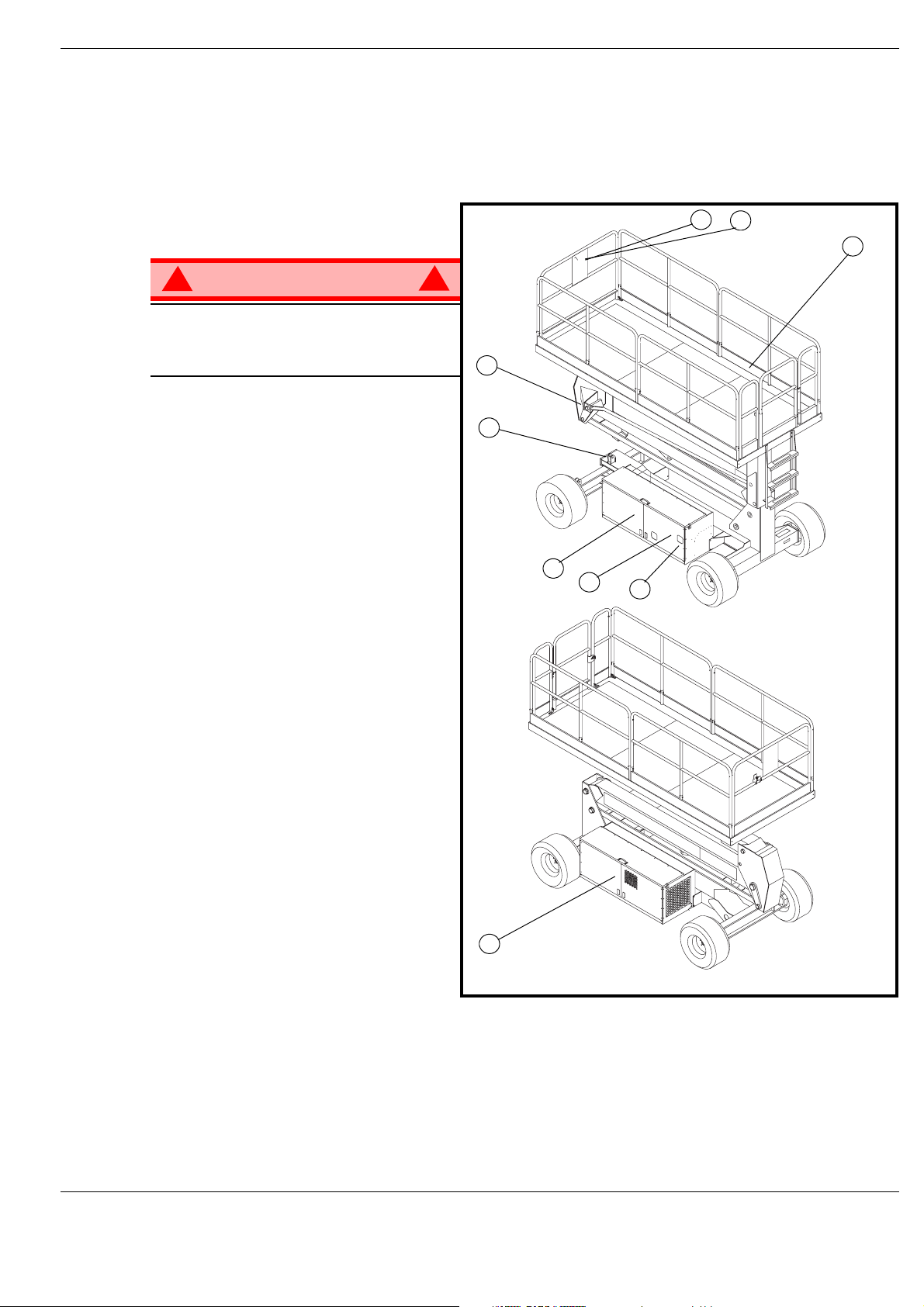
Introduzione
I
NTRODUZIONE
Questo manuale riguarda il funzion am e nt o de lle piatt aform e di lavoro semoventi serie SL26/30 Speed
Level. Questo manuale deve essere conservato sempre all'interno della macchina.
D
ESCRIZIONE
1. Piattaforma
GENERALE
Figure 1: Serie SL26/30 SL
7
6
1
!
AVVISO
NON usare la piattaforma di
manutenzione se sprovvista di barriere di
protezione opportunamente assemblate
e posizionate
2. Gruppo di sollevamento
3. Telaio
4. Modulo di alimentazione
5. Modulo di controllo
6. Comandi della piattaforma
7. Custodia per il manuale
8. Comandi telaio
9. Serbatoio del fluido idraulico
!
2
3
5
8
9
4
Manuale d'uso Pagina 3
Page 88

Limitazioni speciali
L
IMITAZIONI
Quando la piattaforma è sollevata gli spostamenti devono avvenire a velocità molto ridotta.
La piattaforma di lavoro può essere sollevata soltanto se posizionata su una superficie piana e stabile.
! !
La funzione di sollevamento deve essere utilizzata SOLTANTO quando la piattaforma di lavoro
è posizionata su una superficie piana e stabile.
La piattaforma di lavoro NON può essere utilizzata su superfici non piane, irregolari e cedevoli.
C
APACITÀ
La capacità massima (occupanti compresi) della MACCHINA dipende dal modello e dalle opzioni,
ed è indicata nelle “Specifiche” a pagina 18.
! !
NON superare la capacità massima o i limiti di occupazione della piattaforma previsti per questa
macchina.
SPECIALI
PERICOLO
DELLA PIATTAFORMA
PERICOLO
F
ORZA
Per forza manuale si intende la forza applicata dagli occupanti ad oggetti quali pareti o altre strutture
poste all'esterno della piattaforma di lavor o.
Il limite massimo di forza manuale consentito è di 200 N (45 libbre) di forza per occupante,
con un massimo di 400 N (90 libbre) per due o più occupanti.
! !
NON superare il limite massimo di f orza manuale indicato per questa macchina.
S
CALA DI
Non azionare mai la macchina quando il vent o supera la velocità di 12,5 km/h (28 miglia/h)
[Scala di Beaufort 6].
CLASSIFICAZIONE
DI BEAUFORT
3 3,4~5,4 12,25~19,4 11,5~17,75 7,5~12,0 Si spostano carta e ramoscelli e le bandiere ondeggiano.
4 5,4~8,0 19,4~28,8 17,75~26,25 12,0~18 Si solleva la polvere, la carta turbina in aria e i rami ondeggiano.
5 8,0~10,8 28,8~38,9 26,25~35,5 18~24,25
6 10,8~13,9 38,9~50,0 35,5~45,5 24,5~31 Si muovono i rami degli alberi. Le linee elettriche sibilano. È difficile aprire l'ombrello.
7 13,9~17,2 50,0~61,9 45,5~56,5 31,0~38,5 Si muovono grossi alberi. Difficoltà a camminare controvento.
m/s km/h piedi/s miglia/h
A
LLARME SOVRACCARICO
Se si solleva un carico pari al 90% del carico di lavoro di sicurezza sul display digitale della scatola di
controllo della piattaforma viene visualizzato il codice di errore “03”. Se nel cesto è presente un carico
superiore al carico di lavoro di sicurezza, tutte le funzioni della macchina vengono disattivate e viene
prodotto un segnale acustico di avviso. Per tornare al funzionamento normale all'interno del cesto deve
essere presente un carico uguale o inferiore al carico di lavoro di sicurezza e occorre riattivare
l'alimentazione premendo e rilasciando il pulsante di arresto di emergenza.
MANUALE
PERICOLO
B
EAUFORT
VELOCITÀ DEL VENTO
CONDIZIONI AL SUOLO
Iniziano a ondeggiare i cespugli. Nei laghetti e negli stagni l'acqua inizia ad incresparsi in modo evidente.
PERICOLO
! !
Non azionare mai la macchina se il carico della piattaforma è superiore alla capacità nominale.
Pagina 4 Manuale d'uso
Page 89

Comandi e indicatori
C
OMANDI
E
INDICATORI
Figure 2: Comandi e indicatori
Comandi della piattaforma
8
7
10
6
1 Trasmissione (Alta velocità)
2. Trasmissione (Bassa velocità)
3. Livellamento
4. Pulsante avvisatore acustico
5. Pulsante di
sollevamento/abbassamento
6. Candela a incandescenza
7. Avviamento motore
8. Pulsante arresto di emergenza
9. Display
1
2
3
2
1
4
Comandi telaio
5
9
6
5
1. Arresto di emergenza
2. Sollevamento
3. Abbassamento
4. Attivazione
5. Candela a incandescenza
6. Avviamento
3
4
Manuale d'uso Pagina 5
Page 90

Ispezione di sicurezza preliminare all'uso
I
SPEZIONE
NOTE: Leggere atten tament e, comprender e e risp et tar e tut te le n orme di sicu rezza, le is truzi oni d 'us o,
1. Aprire i moduli e ispezionarli per individuare eventuali danni, perdite di fluido o componenti mancanti.
2. Controllare il livello del fluido idraulico a
3. Verificare che il livello del liquido della
4. Verificare il livello di carburante diesel
5. Verificare che tutte le barriere di
6. Ispezionare accuratamente la macchina alla ricerca di saldature incrinate e danni strutturali,
DI SICUREZZA
le etichette e le istruzioni/i requisiti nazionali di sicurezza. Prima dell'uso, eseguire
quotidianamente le seguenti operazioni.
piattaforma completamente abbassata .
Il serbatoio del fluido idraulico si trova
nella porta modulo di controllo. Il livello
del fluido deve essere compreso tra le
linee MIN e MAX. Aggiungere fluido
idraulico se necessario.
batteria dell'avviatore sia corretto.
a motore spento. Il serbatoio del
carburante è situato nel modulo di
alimentazione. Aggiungere la quantità
di carburante necessaria.
protezione siano correttamente
posizionate e che tutti i dispositivi di
fissaggio siano opportunamente serrati.
componenti allentati o mancanti, perdite idrauliche, cavi di comando danneggiati, e collegamenti
o bulloni delle ruote allentati.
PRELIMINARE
ALL'USO
Figure 3: Serbatoio idraulico
Pagina 6 Manuale d'uso
Page 91

Ispezione delle funzioni del sistema
I
SPEZIONE
Fare riferimento a Figure 2 (pagina 5) per indicazioni sull'ubicazione dei vari comandi e indicatori.
DELLE
FUNZIONI
DEL
SISTEMA
!
AVVISO
TENERSI A DISTANZA dalla piattaforma di lavoro quando si eseguono i seguenti controlli.
Prima di utilizzare la piattaforma di lavoro, ispezionare l'area di lavoro per ricercare eventuali imperfezioni
superficiali pericolose, quali fori, dislivelli, protuberanze e detriti.
Verificare la presenza di eventuali ostacoli e controllare i conduttori elettrici in TUTTE le direzioni, anche
sopra la piattaforma di lavoro.
Quando si eseguono i controlli, proteggere da eventuali danni il cavo della console di comando.
1. Se necessario, spostare la macchina in un'area priva di ostacoli in modo da poterla sollevare
completamente.
2. Ruotare in posizione di accensione (ON) l'interruttore arresto di emergenza telaio.
3. Ruotare in posizione di accensione (ON) l'interruttore arresto di emergenza piattaforma.
4. Ruotare l'interruttore a chiave in posizione di accensione (ON).
5. Osservare accuratamente il gruppo di sollevamento, il cilindro di sollevamento, i cavi e i flessibili, onde
individuare eventuali saldature incrinate o danni strutturali, componenti allentati, perdite idrauliche,
collegamenti allentati o funzionamenti irregolari. Verificare se vi sono componenti mancanti o allentati.
6. Premere i pulsanti di sollevamento e attivazione del telaio e sollevare completamente la piattaforma.
7. Abbassare parzialmente la piattaforma premendo i pulsanti di abbassamento e attivazione del telaio
e verificare che sia emesso l'allarme di discesa.
8. Aprire la valvole di discesa di emergenza (v. Figure 4) tirando verso di sé la manopola per verificarne
il corretto funzionamento. Quando la piattaforma viene abbassata, rilasciare la manopola.
9. Premere l'interruttore arresto di emergenza telaio per verificarne il corretto funzionamento. Tutte le
funzioni della macchina dovrebbero essere disattiv ate . Ruotare l'int erruttore arresto di emergenza telaio
per ripristinare il sistema.
10. Verificare che il percorso sia sgombro da ostacoli (persone, ostruzioni, detriti), in piano, ed in grado
di sostenere carichi su ruote.
11. Montare la piattaforma e chiudere correttamente l'ingresso.
12. Selezionare la modalità di marcia (DRIVE).
!
NOTE: Se applicabile, usare sia la marcia alta (HI) sia quella bassa (LOW) quando si esegue questo
passaggio.
13. Attivare la levetta dell'interblocco di sicurezza e contemporaneamente portare il joystick
in avanti (FORWARD) e indietro (REVERSE) per verificare il controllo della velocità.
14. Spingere l'interruttore sterzo a DESTRA e quindi a SINISTRA per verificare il controllo dello sterzo.
15. Selezionare la modalità di sollevamento (LIFT). Afferrare il joystick, attivando contemporaneamente la
levetta dell'interblocco di sicurezza e spingerlo in avanti per controllare i comandi di sollevamento della
piattaforma. Sollevare completamente la piattaforma.
16. Tirare indietro il joystick. La piattaforma dovrebbe abbassarsi e si dovrebb e sentire il segnale di allarme
di discesa.
17. Premere l'interruttore arresto di emergenza piattaforma per verificarne il corretto funzionamento. Tutte
le funzioni della macchina dovrebbero essere disattivate. Tirare l'interruttore arresto di emergenza
piattaforma per ripristi na re il sistema.
Manuale d'uso Pagina 7
Page 92

Funzionamento
F
UNZIONAMENTO
Prima di utilizzare la piattaforma di lavoro, assicurarsi di aver completato l'ispezione di sicurezza
preliminare all'uso e di av er corretto e v entuali prob lemi. Non utilizzare mai la macc hina se danneggiata
o malfunzionante. L'operatore che utilizza la macchina deve essere opportunamente addestrato.
A
VVIAMENTO
1. Montare la piattaforma e chiudere correttamente l'ingresso.
2. Abbassare e tenere premuto il pulsante della candela a incandescenza per circa 5 secondi.
3. Premere il pulsante di avviamento verde.
S
POSTAMENTO
1. Verificare che il percorso sia sgombro da ostacoli (persone, ostruzioni, fori, dislivelli, protuberanze
e detriti), in piano e in grado di sostenere carichi su ruote.
2. Verificare che il motore sia avviato e che l'interruttore arresto di emergen za telaio sia in posizione
di accensione (ON - estratto).
3. Montare la piattaforma e chiudere correttamente l'ingresso.
4. Verificare che siano rispettati gli spazi minimi richiesti al di sopra, al di sotto e ai lati della piattaforma.
5. Ruotare in posizione di accensione (ON) l'interruttore arresto di emergenza piattaforma.
6. Selezionare la modalità di marcia (DRIVE).
DEL MOTORE
A
PIATTAFORMA ABBASSATA
NOTE: Scegliere tra la coppia di trasmissione standard o quella extra a seconda del la pendenza.
7. Attivare la levetta dell'interblocco di sicurezza e spostare il joystick in avanti (FORWARD)
e indietro (REVERSE) per raggiungere la direzione desiderata. La velocità della macchina varia
a seconda della distanza del joystick dal centro.
S
TERZO
1. Ruotare l'interruttore di marcia/sollevamento in posizione di MARCIA (DRIVE).
2. Attivare la levetta dell'interblocco di sicurezza e contemporaneamente spingere l'interruttore sterzo
verso DESTRA o SINISTRA per girare le ruote nella direzione desiderata. Osservare le ruote durante
la manovra della piattaforma di lavoro per verificare che la direzione sia corretta.
NOTE: Lo sterzo non è autoc entrante. Le ruote devono essere riportate in posizione allineata
azionando l'interruttore sterzo.
S
OLLEVAMENTO
1. Scegliere una superficie piana e stabile.
2. Selezionare la modalità di sollevamento (LIFT).
3. Attivare la levetta dell'interblocco di sicurezza e contemporaneamente spingere in avanti il joystick.
4. Se la macchina non è in piano sarà riprodotto l'allarme antiribaltamento e non sarà possibile sollevare
o azionare la macchina.
5. Se l'allarme antiribaltamento suona, abbassare completamente la piattaforma, sollevarla di
circa 600 mm, arrestarla e tenere quindi premuto il pulsante di livellamento fino allo spegnimento
dell'allarme. È quindi possibile sollevarla completamente. Se la piattaforma non è disposta
correttamente in piano, l'allarme antiribaltamento continuerà a suonare e le funzioni di sollevamento
si limiteranno a un'altezza di circa 2 m.
DELLA
PIATTAFORMA
Pagina 8 Manuale d'uso
Page 93

Funzionamento
S
POSTAMENTO
NOTE: La macchina si sposta a velocità ridotta quando la piattaforma è sollevata.
1. Verificare che il percorso sia sgombro da ostacoli (persone, ostruzioni, fori, dislivelli, protuberanze
e detriti), in piano e in grado di sostenere carichi su ruote.
2. Verificare che siano rispettati gli spazi minimi richiesti al di sopra, al di sotto e ai lati della piattaforma.
3. Selezionare la modalità di marcia (DRIVE).
4. Attivare la levetta dell'interblocco di sicurezza sul joystick e spostarlo in avanti (FORWARD)
e all'indietro (REVERSE) per raggiungere la direzione desiderata. La velocità della macchina varia
a seconda della distanza del joystick dal centro.
5. Se la macchina non è in piano sarà riprodotto l'allarme antiribaltamento e non sarà possibile sollevarla
o azionarla. Se l'allarme antiribaltamento suona, abbassare la piattaf orma e spostare la macchina su
una superficie piana e stabile prima di provar e a risollevare la piattaforma.
A
BBASSAMENTO
1. Selezionare la modalità di sollevamento (LIFT).
2. Controllare l'area into rno alla base della piattaforma per accertarsi che non vi siano person e a cont at to
con la macchina. Attivare la levetta dell'interblocco di sicurezza e tirare il joystick per abbassare la
piattaforma.
3. La piattaforma si arresterà una volta raggiunta l'altezza di sicurezza per la movimentazione senza
l'ausilio di dispositivi di protezione personali. Controllare l'area intorno alla base della piattaforma per
accertarsi che non vi siano persone a contatto con la macchina. Dopo circa quattr o secondi, ab bassare
la piattaforma come descritto al passaggio 2.
A
PIATTAFORMA SOLLEVATA
DELLA
PIATTAFORMA
M
ESSA
La funzione di livellamento automatico conse nte di posizionare in piano la piattaforma quando il terreno
non supera un'inclinazione di 13 gradi in senso trasversale e di 9 gradi in senso longitudinale. Se la
pendenza è superiore a questi due valori, la funzione di livellamento automatico non sarà disponibile.
L'allarme antiribaltamento continuerà a suonare fino al livellamento completo della piattaforma
1. Verificare che il percorso sia sgombro da ostacoli (persone, ostruzioni, fori, dislivelli, protuberanze
e detriti), in piano e in grado di sostenere carichi su ruote.
2. Verificare che siano rispettati gli spazi minimi richiesti al di sopra, al di sotto e ai lati della piattaforma.
3. Sollevare la piattaforma di circa 600 mm (2 piedi).
4. Tenere premuto il pulsante di livellamento automatico e la levetta dell'interblocco di sicurezza fino a
quando la piattaforma non è messa completamen te in piano e l'allarme antiribaltamento non è spento.
5. In questa situazione sono disponibili esclusivamente le funzioni di sollevamento e di abba ssamento.
6. Per effettuare l'azionamento, abbassare e riportare la piattaforma alla sua normale inclinazione.
A
LIVELLO
DELLA PIATTAFORMA
Manuale d'uso Pagina 9
Page 94

Funzionamento
D
ISCESA
DI EMERGENZA
Figure 4: Valvola di discesa di emergenza
!
AVVISO
Se la piattaforma non si abbassa,
NON salire MAI sul gruppo di sollevamento.
Tenersi a distanza dal gruppo di
sollevame nto quando si aziona la m anopola
della valvola di discesa di emergenza.
SL26/30 S
La valvola di discesa di emergenza per
SL26/30 è situata nel modulo di controllo
della macchina ed è accessibile attraverso
un'apertura nella porta del modulo di
controllo.
1. Aprire la valvola di discesa di emergenza tenendo tirata la maniglia.
2. Per chiuderla, rilasciare la manopola. Non è possibile sollevare la piattaforma se la valvola di discesa
di emergenza è aperta.
PEED
L
EVEL
!
Manopola per discesa di emergenza
Pagina 10 Manuale d'uso
Page 95

Funzionamento
R
IPIEGARE
Questa procedura è applicabile esclusivame nte al modello SL26/30 Speed Level e serve a consentirne
il passaggio attraverso un portone a due battenti standard. Le barriere di protezione devono essere
riposte nella posizione corretta prima di utilizzare la macchina.
P
ROCEDURA DI RIPIEGAMENTO
1. Sganciare il dispositivo di controllo dalla barriera di protezione laterale e posizionarlo sul pavimento
della piattaforma.
2. Iniziando dalla parte anteriore della piattaforma, rimuovere i dadi, i bulloni e le rondelle dalla parte
superiore della barriera di protezione anteriore. Ripiegare la barriera di protezione anteriore sulla
piattaforma.
3. Chiudere e bloccare il cancelletto.
4. Rim uovere i dadi, i bulloni e le rondelle dalla parte superiore della barriera di protezione posteriore.
Ripiegare la barriera di protezione posteriore sulla piattaforma, facendo attenzione a tenerla sempre
bloccata.
5. Rimuovere i dadi, i bulloni e le rondelle dalla parte superiore delle barriere di protezione laterali.
Sollevare e ripiegare una barriera di protezione laterale in modo che appoggi sul ponte. Ripetere
lo stesso procedimento con le altre barriere di protezione laterali.
P
ROCEDURA DI SOLLEVAMENTO
1. Sollevare le barriere di protezione laterali, verificando che siano tutte abbassate, in modo da fissare la
barriera di protezione in posiz ion e verticale.
2. Montare i bulloni, le rondelle e i dadi tra le barriere di prote zione laterali e serrarli opportunamente.
3. Sollevare il gruppo barriere di protezione posteriori, allineando i fori e montando i bulloni, le rondelle
e i dadi. Serrare opportunamente.
LE BARRIERE
DI PROTEZIONE
PERICOLO
! !
Prima di inserire la piattaforma, le
barriere di protezione devono
essere fissate saldamente nella
posizione corretta.
Manuale d'uso Pagina 11
Page 96

Rimorchio o sollevamento mediante verricello
R
IMORCHIO
Eseguire la seguente procedura soltanto quando la macchina non è sotto controllo diretto e deve essere
spostata oppure quando deve essere sollevata mediante verricello su un veicolo di trasporto
(fare riferimento a “Trasporto della piattaforma di lavoro” a pagina 13).
O
SOLLEVAMENTO
MEDIANTE
VERRICELLO
AVVERTENZA
NON trainare o sollevare mediante verricello la macchina a una velocità superiore
a0,3m/s(1piede/s). Se si supera la velocità indicata si danneggeranno i componenti
della trasmissione con conseguente annullamento della garanzia.
P
OMPA
Eseguire la seguente procedura soltanto quando la macchina non è sotto controllo diretto e deve
essere spostata oppure quando per essere trasportata viene sollevata su un piano inclinato o su
una motrice.
1. Chiudere la valvola ad ago ruotando la vite a brugola esagonale in senso orario.
2. Azionare la pompa di rilascio del freno fino a quando i freni non sono rilasciati.
3. Ora la macchina si sposta se viene spinta o tirata.
4. Assicurarsi di aprire la valvola ad ago e verificare che lo stelo del cilindro sia allungato prima
di avviare la macchina.
DI RILASCIO
DEL
FRENO
Pompa a mano
Valvola ad ago
!
AVVISO
Non trainare mai la macchina ad una velocità superiore a 0,3 m/s (1 piede/s).
Non azionare mai la piattaforma di lavoro quando il freno di stazionamento è rilasciato. Si potrebbero
causare lesioni gravi o danni all'apparecchio.
D
OPO
1. Assicurarsi che la piattaforma si a com p let am e nt e abbas sa ta .
2. Parcheggiare la macchina su una superficie piana e stabile, possibilmente al coperto e perciò al riparo
da atti vandalici, bambini e da eventuali utilizzi non autorizzati.
3. Ruotare la chiave interruttore telaio in posizione di spegnimento (OFF) e togliere la chiave per evitare
eventuali utilizzi non autorizzati.
C
ONTATORE
Per accedere alla funzione contatore ore procedere nel modo seguente.
1. Salire sul cesto (a macchina avviata)
2. Premere il pulsante arresto di emergenza piattaforma.
3. Premere i pulsanti di avvisatore acustico e sollevamento.
4. Tenendo premuti i pulsanti, ruotare il pulsante arresto di emergenza per ripristinare l'alimentazione
della macchina.
5. Sul display sarà visualizzato “hr ” e premendo il pu lsante de stro si scorr er à il nu mero di o re accumu late
di due cifre per volta. Per esempio, premendo il pulsante destro una volta viene visualizzato “20”,
premendolo una seconda volta viene visualizza to “58”, mentre premendolo una terza v olta viene
visualizzato “hr”: il tempo di funzionamento totale è di 2058 ore.
L'
USO
QUOTIDIANO
ORE
!
Pagina 12 Manuale d'uso
Page 97

Trasporto della piattaforma di lavoro
T
RASPORTO DELLA
P
REPARAZIONE PER
1. Abbassare completame n te la pia tt aform a.
2. Scollegare il cavo negativo della batteria (-) dal morsetto.
3. Legare il dispositivo di controllo alla barriera di protezione anteriore.
4. Fissare la struttura di sollevamento al telaio.
S
OLLEVAMENTO
1. Fissare le cinghie soltanto agli occhielli di fissaggio/sollevamento del telaio.
2. Posizionare la piattaforma sul veicolo in posizione di trasporto.
3. Bloccare le ruote.
4. Fissare la piattaforma di lavoro al veicolo di trasporto applicando catene o cinghie di capacità adeguata
agli occhielli di sollevamento/fissaggio del telaio.
A
MEZZO ELEVATORE
PERICOLO
! !
L'uso di elevatori a forche è consentito soltanto per le operazioni di trasporto.
Fare riferimento alle specifiche relative al peso della piattaforma di lavoro e assicurarsi che l'elevatore
a forche sia in grado di sollevare la piattaforma.
PIATTAFORMA DI LAVORO
LA SPEDIZIONE
A
MEZZO GRU
A
FORCHE
Applicare l'elevatore a forche sul lato, sollevando la macchina da sotto i moduli del telaio.
Figure 5: Trasporto della piattaforma di lavoro
T
RASPOR TO O
SOLLEVAMENTO
VERRICELLO
CAMION
NOTE: Non azionare il verricello a una velocità
superiore a 0,3 m/s (1 piede/s).
1. Spostare la macchina sul camion o sulla motrice;
A. Per
a. Portare la piattaforma sulla rampa in posizione di
trasporto.
b. Raddrizzare le ruote e spegnere la macchina.
c. Bloccare le ruote.
B. Per sollevare mediante verricello la macchina
sul veicolo di trasporto:
a. Portare la piattaforma di lavoro sulla rampa.
b. Collegare il cavo del verricello agli occhielli di
fissaggio/sollevamento.
c. Rilasciare i freni di stazionamento (fare riferimento a “Rimorchio o sollevamento mediante verricello”
a pagina 12).
d. Sollevare la piattaforma con il verricello e portarla in posizione di trasporto
e. Bloccare le ruote.
2. Fissare la piattaforma di lavoro al veicolo di trasporto applicando catene o cinghie di capacità adeguata
agli occhielli di fissaggio/sollevamento del telaio.
O
condurre
UNA
la macchina sul veicolo di trasporto:
A
SU UN
MOTRICE
MEZZO
Occhielli di
fissaggio/
sollevament
o anteriori
Elevator e a forche
Occhielli di fissaggio/sollevamento
AVVERTENZA
Se si stringono eccessivamente le catene o le cinghie collegate agli occhielli di fissaggio/sollevamento
si potrebbe danneggiare la piattaforma di lavoro.
Manuale d'uso Pagina 13
Page 98

Manutenzione
M
ANUTENZIONE
!
AVVISO
Se la piattaforma è sollevata, prima di eseguire operazioni di manutenzione bloccare il gruppo
di sollevamento.
NON sostare in piedi nell'area circostante il gruppo di sollevamento quando si stende o si conserva
il braccio.
B
LOCCAGGIO
GRUPPO
SOLLEVAMENTO
DI
DEL
!
Figure 6: Braccio a forbice
INSTALLAZIONE
1. Parcheggiare la piattaforma di lavoro su un
terreno piano e stabile e lasciare il motore
in funzione.
2. Verificare che l'interruttore di arresto
di emergenza telaio sia in posizione
di accensione (ON).
3. Tenere premuti i pulsanti di sollevamento
e attivazione del telaio per sollevare la
piattaforma di circa 305 mm.
4. Colloca re un supporto con un valore nominale minimo di 1814 kg tra il montante inferiore e il telaio,
proprio dietro all'asse anteriore.
5. Tenere premuti i pulsanti di abbassamento e attivazione del telaio per abbassare la piattaforma fino
a quando il supporto non è fissato saldamente tra il montante inferiore e il telaio.
RIMOZIONE
1. Tenere premuti i pulsanti di sollevamento e attivazione del telaio per sollevare la piattaforma fino
a quando è possibile rimuovere il supporto.
2. Rimuovere il supporto.
3. Tenere premuti i pulsanti di abbassamento e attivazione del telaio per abbassare completamente
la piattaforma.
Pagina 14 Manuale d'uso
Page 99

Manutenzione
M
ANUTENZIONE
DELLE
BATTERIE
!
AVVISO
Pericolo: miscela di gas esplosivi. Tenere le batterie lontano da scintille, fiamme e materiali fumogeni.
Indossare sempre occhiali protettivi quando si lavora in prossimità delle batterie.
Il liquido della batteria è molto corrosivo. Se si rovescia accidentalmente il liquido, risciacquare
accuratamente con acqua pulita.
Sostituire sempre le batterie con batterie originali UpRight o con ricambi approvati dal produttore.
• Controllare quotidianamente il livello del liquido della batteria, soprattutto se la piattaforma di lavoro
viene utilizzata in ambienti caratterizzati da un clima caldo e secco.
• Se il livello di elettroliti è inferiore a 10 mm
distillata. NON usare acqua di rubinetto ricca di minerali, in quanto si accorcerebbe la vita utile della
batteria.
• Mantenere puliti i terminali e i coperchi delle batterie.
• Fare riferimento al manuale di assistenza per allungare la vita utile della batteria e per istruzioni
complete sulle operazioni di manutenzione.
C
ARICAMENTO
La batteria è carica qua ndo il mot or e è in funzio n e.
DELLE BATTERIE
!
3
(
/
poll.) al di sopra delle piastre, aggiungere soltant o acqua
8
Manuale d'uso Pagina 15
Page 100

Manutenzione
C
ODICI
01 - ERRORE INIZ. SISTEMA
02 - ERRORE COM PIATTAFORMA SISTEMA
03 - SOVRACCARICO PIATTAFORMA
04 - ERRORE COM PANNELLO INFERIORE SISTEMA
05 - PRESSIONE OLIO BASSA
06 - TEMP REFRIG. ALTA
21 - AVVIAMENTO PIATTAFORMA ON
22 - SW ROTAZ. SX PIATTAFORMA ON
23 - SW ROTAZ. DX PIATTAFORMA ON
24 - SW SOLLEV. PIATTAFORMA ON
25 - SW MOTOREALTAVEL PIATTAFORMA ON
26 - SW GLOWLP PIATTAFORMA ON
27 - SW MOTOREBASSAVEL PIATTAFORMA ON
28 - SW AUTOLIV. PIATTAFORMA ON
29 - SW ABILIT. JOYSTICK PIATTAFORMA ON
DI ERRORE
31 - JOYSTICK PIATTAFORMA NON NEUTRALE
34 - SW ABIL. PANNELLO TERRA ON
37 - SW PANNELLO TERRA GIÙ ON
38 - SW PANNELLO TERRA SU ON
43 - SW AVVIO PANNELLO TERRA ON
45 - SW GLOWLP PANNELLO TERRA ON
51 - Errore bobina altaVelocità1
52 - Errore bobina altaVelocità2
55 - Errore bobina sollevamento
56 - Errore bobina abbassamento
57 - Errore bobina inclinazione sx
58 - Errore bobina inclinazione dx
59 - Errore bobina svolta dx
61 - Errore bobina svolta sx
62 - Errore bobina inclinazione indietro
63 - Errore bobina inclinazione avanti
66 - Errore bobina avanti
67 - Errore bobina indietro
71 - Errore bobina valvola cuscinetto
72 - Errore bobina asse flottante
73 - Errore bobina spurgo
68 – BATTERIA BASSA
Pagina 16 Manuale d'uso
 Loading...